Experimental Examination of Light Pressure - Annalen Der Physik - Pyotr Lebedev - 1901 - English
26
P.N. Lebede v, Ann . der Ph ysik, 6, 433 1901 EXPERIMENTAL EXAMINATION OF LIGHT PRESSURE P.N. Lebedev (Received 1901) — — ♦ — — Translation from Russian by Soloviev V. — — ♦ — — Explicating the basic standings of the electromagnetic theory of light Maxwell (1873) has paid attention also to those forces which arise to us as ponderomotive forces in every magnetically- or electrically-polarized medium: necessity of existence of these forces inevitably follows from his theory in any bundle of rays also, and Maxwell 1 tells us: In a medium in which waves are propagated there is a pressure in the direction normal to the wave, and numerically equal to the energy contained in unit of volume. The further substantiation of these Maxwell forces of pressure of electro- magnetic waves we discover at O. Heaviside, 2 H. A. Lorentz, 3 E. Cohn, 4 and D. Holdhammer. 5 A. Bartoli (187 6) 6 has come to an identical conclusion following com- pletely different way and, probably, being not informed of the ray property 1 J. С. M a x w e l l, Treatise on electricity and magnetism, § 792. 2 O. H e a v i s i d e, Electromagnetic Theory 1, 334 (London, 1893). 3 H. A. L o r e n t z, Versuch einer Theorie d еr electromagnetischen und optischen Erscheinungen in bewegten K¨ orpern, page 29 (Leid en, 1895). 4 E. C o h n, Das electromagnetische Feld, page 543 (Leipzig, 1900). 5 D. H o l d h a m m e r, Ann. d. Phys. 4, 834 (1901). 6 A. B a r t o l i, Exner’s Re p. d. Ph ysik 21, 198 (1884) German translation from Nuovo Cimento 15, 195 (1883). 1
Transcript of Experimental Examination of Light Pressure - Annalen Der Physik - Pyotr Lebedev - 1901 - English

8/3/2019 Experimental Examination of Light Pressure - Annalen Der Physik - Pyotr Lebedev - 1901 - English
http://slidepdf.com/reader/full/experimental-examination-of-light-pressure-annalen-der-physik-pyotr-lebedev 1/26
P.N. Lebedev, Ann. der Physik, 6, 433 1901
EXPERIMENTAL EXAMINATION OF LIGHT PRESSURE
P.N. Lebedev(Received 1901)
— — ♦ — —Translation from Russian by Soloviev V.
— — ♦ — —
Explicating the basic standings of the electromagnetic theory of lightMaxwell (1873) has paid attention also to those forces which arise to us asponderomotive forces in every magnetically- or electrically-polarized medium:
necessity of existence of these forces inevitably follows from his theory in anybundle of rays also, and Maxwell 1 tells us:
In a medium in which waves are propagated there is a pressure in thedirection normal to the wave, and numerically equal to the energy containedin unit of volume.
The further substantiation of these Maxwell forces of pressure of electro-magnetic waves we discover at O. Heaviside, 2 H. A. Lorentz, 3
E. Cohn, 4 and D. Holdhammer. 5
A. Bartoli (1876) 6 has come to an identical conclusion following com-pletely different way and, probably, being not informed of the ray property
1
J.С
. M a x w e l l, Treatise on electricity and magnetism,§
792.2O. H e a v i s i d e, Electromagnetic Theory 1, 334 (London, 1893).3H. A. L o r e n t z, Versuch einer Theorie d еr electromagnetischen und optischen
Erscheinungen in bewegten Korpern, page 29 (Leiden, 1895).4E. C o h n, Das electromagnetische Feld, page 543 (Leipzig, 1900).5D. H o l d h a m m e r, Ann. d. Phys. 4, 834 (1901).6 A. B a r t o l i, Exner’s Rep. d. Physik 21, 198 (1884) German translation from
Nuovo Cimento 15, 195 (1883).
1

8/3/2019 Experimental Examination of Light Pressure - Annalen Der Physik - Pyotr Lebedev - 1901 - English
http://slidepdf.com/reader/full/experimental-examination-of-light-pressure-annalen-der-physik-pyotr-lebedev 2/26
indicated by Maxwell. Bartoli specifies circular processes, which should en-
able by means of moving mirrors to transfer a radiant energy from a morecold body to a warmer one, and evaluates the work, which should be donein this case according to the second law of thermodynamics. Necessity toexpend a work by moving a mirror towards the impinging beam forces toassume, that the impinging beam presses on a mirror. Bartoli has calculateda value of this pressure; the effect obtained by him completely coincides withthe effect obtained by Maxwell.
Boltzmann 1 has followed along the path indicated by Bartoli at evalu-ations of pressure of beams, and then Prince B. B. Galitzine 2 andGuillaume, 3 and Drude has extended this method onto the absolutely blackbody. 4
If a parallel bundle of beams impinges steeply on a flat surface, theamount of Maxwell-Bartoli pressure is determined by the amount of energy, impinging per second, by reflectivity of a surface and by velocity v of thebeam propagation; then
ρ =E
v(1 + ρ),
where ρ is in the range between 0 for the absolutely black surface and 1 forthe absolutely reflecting surface.
The value of this beam pressure is rather small. Both Maxwell andBartoli have calculated that the Sun rays, impinging steeply on a flat surfaceof 1 m2, should yield pressure, which in a case of a black surface is equal to
0,4 mg, and in case of a mirror — 0,8 mg.The assumptions that the beams of light should yield pressure, were
expressed already much earlier. So, Kepler (1619), trying to explain thespecific shape of comet tails, for the first time has stated an idea, that thisshape is stipulated by pressure of solar beams on particles of substance of tails; this guess was in the complete accordance with a outflow hypothesisprevailed that time and has found hot support from Longomontanus(1622). 5 The same effect has inspired L. Euler (1746) 6 to assign pressingforces to a light beam, and he has made attempt to justify them theoretically,viewing a light wave (according to Huygens) as longitudinal oscillations.
1L. B o l t z m a n n. Wied. Ann. 22, pages 33, 291, 616 (1884).2 B. G a l i t z i n e, Wied. Ann, 47, 479 (1892).3Сh. Ed. G u i l l a u m e, Archives des Sciences phys. et nat. de Geneve 31, 121
(1894).4P. D r u d e, Lehrbuch der Optik, page 447 (Leipzig, 1900).5See below in de Mairan, page 355-356.6L. E u l e r, Histoire de l’Academie de Berlin 2, 121 (1746).
2

8/3/2019 Experimental Examination of Light Pressure - Annalen Der Physik - Pyotr Lebedev - 1901 - English
http://slidepdf.com/reader/full/experimental-examination-of-light-pressure-annalen-der-physik-pyotr-lebedev 3/26
De Mairan (1754) 7 has undertaken together with Du Fay the first rather
interesting experiments to be convinced of validity of the guesses mentionedabove, but he should leave them, as the convectional currents in an ambientair hindered the observation of a guessed effect. If to take into considera-tion those resorts, which could be arranged by the experimenter in XVIIIcentury, De Mairan experiments deserve the greatest surprise. The simi-lar experiments were undertaken then by Fresnel (1825), 8 who have beenstopped by the same difficulties; detailed study of appearances having herea place, has lead W. Crooks 9 to discovery of radiometric forces.
Maxwell-Bartoli forces of beam pressure can in due course receive a greatvalue in problems of physics and astronomy, that is why the experimentalexamination of these forces is even more advisable, as their theoretical sub-
stantiations both according to Maxwell and to Bartoli are based on particu-lar partial properties of absorbing and reflecting surfaces, and consequentlythere can be a problem, whether the forces of pressure are really stipulatedonly by these partial properties of surfaces in a case of light rays also. Thisproblem can be solved only through extra examinations; the most direct wayis the immediate experience.
Attempts by F. Zollner 1 and Bartoli (cited above, page 205), madein this direction have not given positive results; that is why I also haveundertaken the following experimental examination of light pressure. 2
I. Preliminary experimentsIn his textbook Maxwell (§ 793) tells us:
It is probable that a much greater energy of radiation might be obtainedby means of the concentrated rays of the electric lamp (than solar light).Such rays falling on a thin metallic disk, delicately suspended in a vacuum,might perhaps produce an observable mechanical effect.
When I started with the experiments, I supposed that the arrangementindicated by Maxwell does not lead to the goal as F. Zo llner 3 has already
7De M a i r a n, Traite physique et historique de l’Aurore Boreale (Seconde Edition),page 371 (Paris, 1754).
8A. F r e s n e l, Ann. de Chimie et de Phys. (2) 29, 57, 107 (1825).9W. C r o o k s, Philos. Transact. of the R. S. of London 164, 501 (1874); in this
article there is a list of references concerned here.1F. Zo l l n e r, Pogg. Ann. 160, 154 (1877).2a draft Report about this examination was made by me on the First International
Congress of Physics in Paris (in August 1900); the translation of contribution is publishedin Zhurnal Rossijskogo Fiziko-Khimicheskogo Obschestva (Fizika) 32 (1), page 211, 1900.
3F. Z o l l n e r, cited above, page 155.
3

8/3/2019 Experimental Examination of Light Pressure - Annalen Der Physik - Pyotr Lebedev - 1901 - English
http://slidepdf.com/reader/full/experimental-examination-of-light-pressure-annalen-der-physik-pyotr-lebedev 4/26
failed on this way; also he has paid attention to the circumstance, that
numerical quantity (of the light pressure), theoretically predicted by theMaxwell, is approximately 100 000 times less then observed by Crooks inone special case. 4 If it was even possible to hope to reduce in a veryconsiderable measure these secondary radiometric forces, nevertheless, itseemed to me, that only such experiment could have the desisive meaning,in which it would be possible to cancel somehow the activity of these forces.
At examination of radiometric forces Schuster5 has shown, that they areinterior forces of a radiometer; Righi 6 confirmed this result by a very refinedexperiment: “I have arranged so, — Righi tells us, — that the radiometerfloated on a surface of water upside down; the glass cap of a mill laid thuson that tube, which is ordinary retains a rotaried rod of a mill in a vertical
standing. Due to this there were frictional force, not allowing a gyration of a mill. When I now have guided on a wing of a mill a strong beam of a light,I could not detect slightest gyration (of the radiometer).”
Both Bertin and Garbe 1 came to the same conclusion in repeating thisexperiment.
Wishing to detect in experiment Maxwell-Bartoli forces of light pressure,I have taken advantage of Righi’s arrangement in such a way: a mica platewas fixed between two circles which have been cut out from a thin nickelleaf bent as the cylinder. The cylinder served as a body of the radiometer;inside it there was a winglet immobilely fastened with it. This radiometerwas suspended on a glass hairline inside the evacuated glass bulb. When I
guided a light of an arc lamp onto the winglet, I permanentlyobserved 2 deviations, which were of the same order as ones evaluated ac-cording to Maxwell-Bartoli. 3
When, during these preliminary experiments, I began to study for com-
4Zollner has put too small energy for a radiation of candle in basis of the calculation.If compare radiometric forces observed by E. Nichols (Wied. Ann. 60, 405 (1897)), withthose forces of pressure evaluated according to Maxwell and Bartoli from Angstrom (Wied.Ann. 67, 647 (1899)) data, concerning radiation of a new candle, the relation gained isabout 10 000.
5A. S c h u s t e r, Phil. Mag. (5) 2, 313 (1876).6А. R i g h i, the literal translation is given at Bertin et Garbe, see below.
1B e r t i n et G a r b e, Ann. de Chim. et de Phys. (5) 11, 67 (1877).2If Righi and also Bertin and Garbe have not noted any Maxwell - Bartoli forces, it
follows extremely that their arrangement calculated for much more radiometric forces, wasinsufficiently sensitive to measure forces of light pressure.
3Results of these preliminary experiments were reported on May 17, 1899 at sessionSociete Vaudoise in Lausanne (Arch. des Sc. phys. et nat. Geneve 8, 184 (1899)). Thecasual circumstances have interfered and prevented opportune appearence of a detailednote planned, and it has remained not printed.
4
8/3/2019 Experimental Examination of Light Pressure - Annalen Der Physik - Pyotr Lebedev - 1901 - English
http://slidepdf.com/reader/full/experimental-examination-of-light-pressure-annalen-der-physik-pyotr-lebedev 5/26
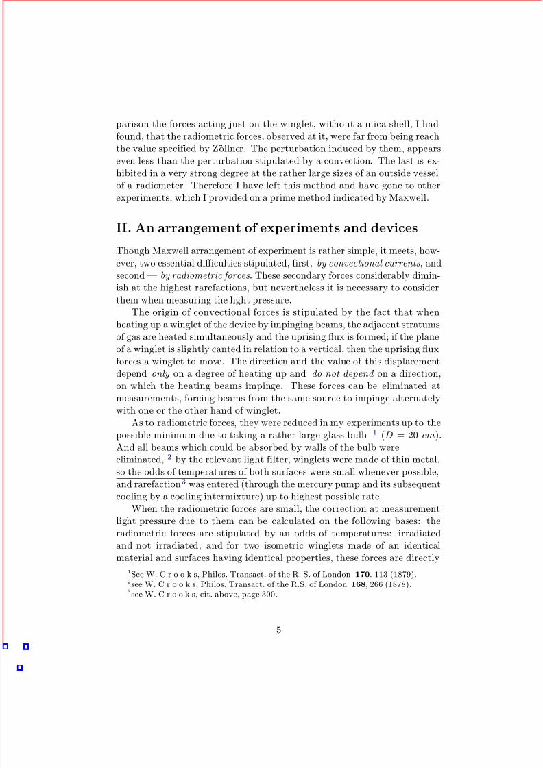
parison the forces acting just on the winglet, without a mica shell, I had
found, that the radiometric forces, observed at it, were far from being reachthe value specified by Zollner. The perturbation induced by them, appearseven less than the perturbation stipulated by a convection. The last is ex-hibited in a very strong degree at the rather large sizes of an outside vesselof a radiometer. Therefore I have left this method and have gone to otherexperiments, which I provided on a prime method indicated by Maxwell.
II. An arrangement of experiments and devices
Though Maxwell arrangement of experiment is rather simple, it meets, how-ever, two essential difficulties stipulated, first, by convectional currents, andsecond — by radiometric forces. These secondary forces considerably dimin-ish at the highest rarefactions, but nevertheless it is necessary to considerthem when measuring the light pressure.
The origin of convectional forces is stipulated by the fact that whenheating up a winglet of the device by impinging beams, the adjacent stratumsof gas are heated simultaneously and the uprising flux is formed; if the planeof a winglet is slightly canted in relation to a vertical, then the uprising fluxforces a winglet to move. The direction and the value of this displacementdepend only on a degree of heating up and do not depend on a direction,on which the heating beams impinge. These forces can be eliminated at
measurements, forcing beams from the same source to impinge alternatelywith one or the other hand of winglet.As to radiometric forces, they were reduced in my experiments up to the
possible minimum due to taking a rather large glass bulb 1 (D = 20 cm).And all beams which could be absorbed by walls of the bulb wereeliminated, 2 by the relevant light filter, winglets were made of thin metal,so the odds of temperatures of both surfaces were small whenever possible,and rarefaction3 was entered (through the mercury pump and its subsequentcooling by a cooling intermixture) up to highest possible rate.
When the radiometric forces are small, the correction at measurementlight pressure due to them can be calculated on the following bases: the
radiometric forces are stipulated by an odds of temperatures: irradiatedand not irradiated, and for two isometric winglets made of an identicalmaterial and surfaces having identical properties, these forces are directly
1See W. C r o o k s, Philos. Transact. of the R. S. of London 170. 113 (1879).2see W. C r o o k s, Philos. Transact. of the R.S. of London 168, 266 (1878).3see W. C r o o k s, cit. above, page 300.
5
8/3/2019 Experimental Examination of Light Pressure - Annalen Der Physik - Pyotr Lebedev - 1901 - English
http://slidepdf.com/reader/full/experimental-examination-of-light-pressure-annalen-der-physik-pyotr-lebedev 6/26
proportional to thicknesses 4 of winglets. If we shall observe simultaneously
two identical winglets having very considerable odds of thickness, we cancalculate, how great would be the deviation called by a light bundle if thethickness of a winglet is equal to zero, that corresponds also to radiometricforces equal to zero. I shall allow myself to note here, that it is necessary todo this corrections only for platinized winglets; at winglets with reflectingsurfaces the radiometric forces are so small, against expectation, that theydisappear in inevitable errors of observations stipulated by other reasons.
Apart from secondary forces of the known nature mentioned above itis possible to specify also a probable hypothesis, that the pulverization of irradiated bodies, unclosed by the Lenard and Wolf, 5 can be accompaniedby noticeable reactionary forces, which are inevitable satellites of Maxwell-
Bartoli forces of a light pressure; these hypothetical additional forces should,however, depend both on a wave length of an impinging light, and on thechemical nature of a winglet; experiments with colour light filters and withdifferent winglets mentioned below have not given opportunities to detectsome noticeable impact of these hypothetical reactionary forces.
The general arrangement of devices was the following (fig. 1, plan):The image of a carbon crater B(+) of the arc lamp (30 amperes) was ag-
glomerated through the condenser C onto a metal diaphragm D(d = 4 mm).The divergent bundle of beams, emergent from a diaphragm, impinged ona lens K and went further as a parallel bundle; to liberate the bundle frominfrared beams there was a glass vessel, behind a lens K , with parallel plate
walls W , filled with pure water 1 (thickness of a stratum was 1 cm); tochange colouring of beams, it was possible to position in this place additionalred ((photographic)) glass or to exchange pure water by a blue ammoniacsolution of the copper salt. 2
On the further trajectory the parallel beam underwent three-multiplereflection from glass (amalgamated) mirrors S 1, S 2 and S 3 and, being ag-
4In my experiments the odds of temperatures between irradiated winglet and walls of the bulb were many times more, than the odds of temperatures between two surfaces of the winglet. To what function of the first odds of temperatures there corresponds quantityof radiometric forces, their ponderomotive impact on a winglet represents their differenceon two surfaces of a winglet, and this last, with a sufficient degree of approximation, is
directly proportional to the second odds of temperatures5Ph. L e n a r d and M. W o l f, Wied. Ann. 37, 455 (1889).1This expedient eliminated all beams λ > 1, 2 µ; from another side, the glass lenses
impede ultraviolet beams.2At red, and also at blue light filter the amount of transiting light energy is reduced up
to the one fifth of the white light; It serves the proof that the beams, which were necessaryto experiment, almost exclusively belonged to to a visual part of a spectrum.
6

8/3/2019 Experimental Examination of Light Pressure - Annalen Der Physik - Pyotr Lebedev - 1901 - English
http://slidepdf.com/reader/full/experimental-examination-of-light-pressure-annalen-der-physik-pyotr-lebedev 7/26
Figure 1:
glomerated through a lens L1, gave a real enlarged (d = 10 mm) image R
of diaphragms D inside a glass bulb. In the movement of a double mirrorS 1S 4 the bundle of rays transversed a similar trajectory and impinged onthe other hand on a winglet located in a glass bulb. The lenses L1 and
L2 had everyone a focal distance equal to 20 cm and a size equal to 5 cm;thus a conical bundle of light had an angle of convergence equal to 15 o. Allthe gadget with mirrors was firmly connected to a lantern of an arc lamp;this last positioned on slides, through which it was easy for removing froma bulb; the adjusting screws and movement on slides allowed to direct a
bundle of rays on an explored winglet.It was possible to guard results of observations from influence of those
casual springs in luminosity of light, which are inevitably interlinked to avolt arc, only by increasing the number of observations.
To refer a separate series of observations to some medial luminosity of light, the following gadget served: between a lens L1 (fig. 1) and glass
7
8/3/2019 Experimental Examination of Light Pressure - Annalen Der Physik - Pyotr Lebedev - 1901 - English
http://slidepdf.com/reader/full/experimental-examination-of-light-pressure-annalen-der-physik-pyotr-lebedev 8/26
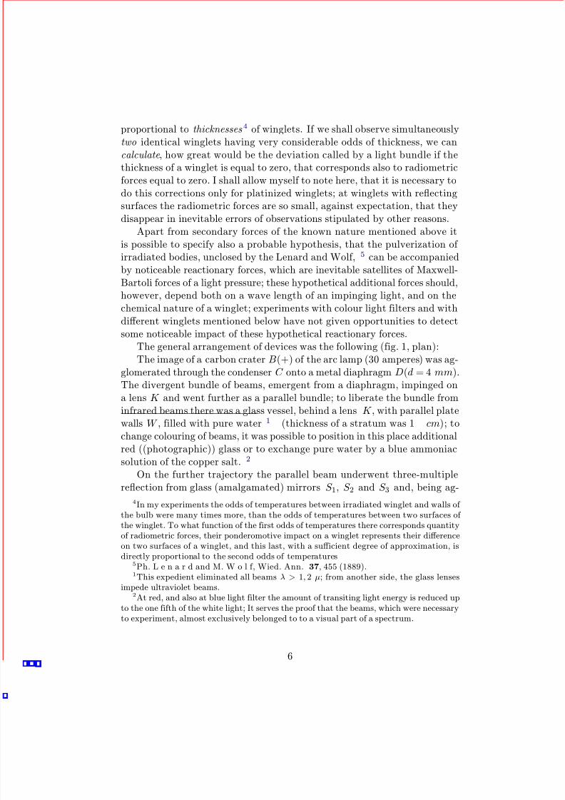
bulb the thin flat plate 1 was posed under a corner in 45o to a direction
of impinging beams. The majority of light freely transits through a plate;the reflex part of light, being agglomerated, gives a real image R1 of thediaphragm, which impinges on a thermopile.
Figure 2:
The thermopile (fig. 2) consisted of fiveelements — “constantan - iron” (thicknessof wires = 0,025 mm), which were hard-ened in a deflate ebonite framework andwere enclosed by glass plates; relative lumi-nosity of an impinging light was measuredby deviations of the D’Arsonval galvanome-ter. To attenuate in an identical degree also
the bundle of rays transiting through a lensL2, the same glass plate 2 was inserted here.
The luminosity of light was checked only in the case when the double mirror
S 1S 4 (fig. 1) was in the indicated standing; at a shift of a double mirror thelight could not impinge on a thermopile, and this standing served for thedefinition of a zeropoint of the galvanometer.
For experiments three different devices (fig. 3) with different wingletswere used.
Figure 3:
Device I (fig. 3, I ) consisted of a glass rod G, to which two crossesmade of a leaf platinum of different thickness were pressed by platinumrings (without the help of a putty); to make winglets (with diameter =5 mm) of all the devices isometric, they should be excised by a steel punch.
8
8/3/2019 Experimental Examination of Light Pressure - Annalen Der Physik - Pyotr Lebedev - 1901 - English
http://slidepdf.com/reader/full/experimental-examination-of-light-pressure-annalen-der-physik-pyotr-lebedev 9/26
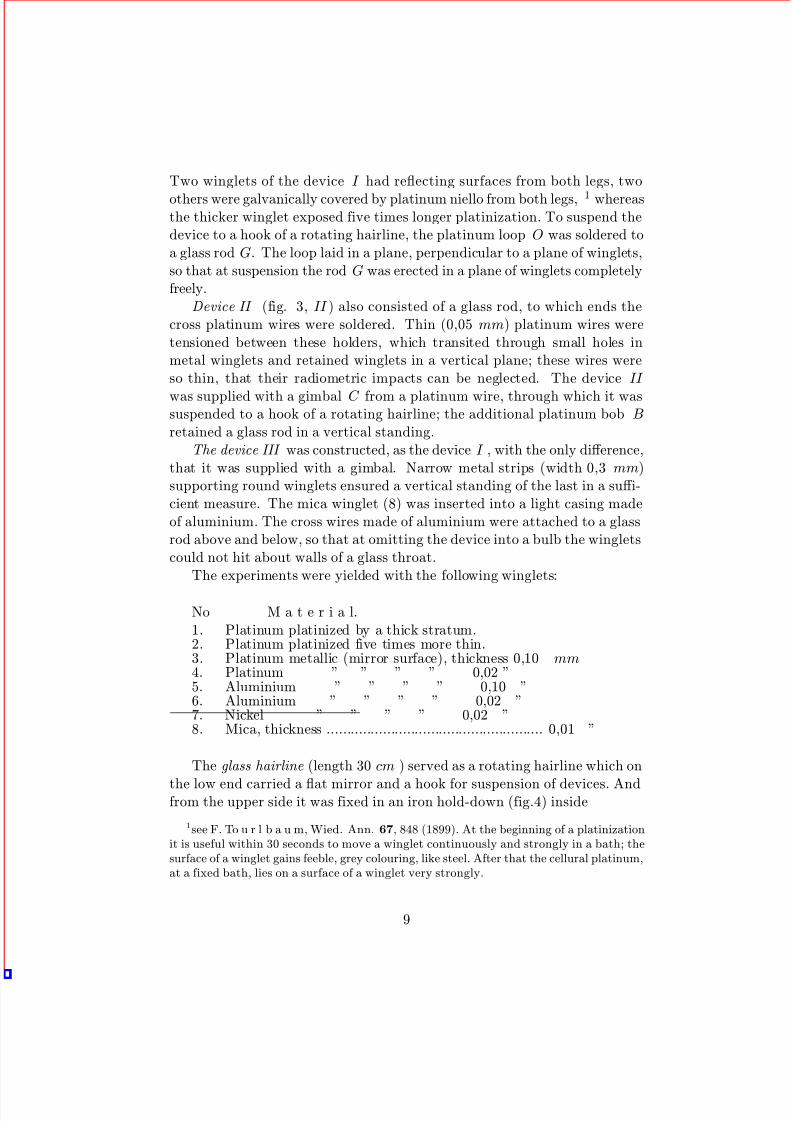
Two winglets of the device I had reflecting surfaces from both legs, two
others were galvanically covered by platinum niello from both legs, 1 whereasthe thicker winglet exposed five times longer platinization. To suspend thedevice to a hook of a rotating hairline, the platinum loop O was soldered toa glass rod G. The loop laid in a plane, perpendicular to a plane of winglets,so that at suspension the rod G was erected in a plane of winglets completelyfreely.
Device II (fig. 3, II ) also consisted of a glass rod, to which ends thecross platinum wires were soldered. Thin (0,05 mm) platinum wires weretensioned between these holders, which transited through small holes inmetal winglets and retained winglets in a vertical plane; these wires wereso thin, that their radiometric impacts can be neglected. The device II
was supplied with a gimbal C from a platinum wire, through which it wassuspended to a hook of a rotating hairline; the additional platinum bob B
retained a glass rod in a vertical standing.The device III was constructed, as the device I , with the only difference,
that it was supplied with a gimbal. Narrow metal strips (width 0,3 mm)supporting round winglets ensured a vertical standing of the last in a suffi-cient measure. The mica winglet (8) was inserted into a light casing madeof aluminium. The cross wires made of aluminium were attached to a glassrod above and below, so that at omitting the device into a bulb the wingletscould not hit about walls of a glass throat.
The experiments were yielded with the following winglets:
No M a t e r i a l.1. Platinum platinized by a thick stratum.2. Platinum platinized five times more thin.3. Platinum metallic (mirror surface), thickness 0,10 mm4. Platinum ” ” ” ” 0,02 ”5. Aluminium ” ” ” ” 0,10 ”6. Aluminium ” ” ” ” 0,02 ”7. Nickel ” ” ” ” 0,02 ”8. Mica, thickness ...................................................... 0,01 ”
The glass hairline (length 30 cm ) served as a rotating hairline which on
the low end carried a flat mirror and a hook for suspension of devices. Andfrom the upper side it was fixed in an iron hold-down (fig.4) inside
1see F. To u r l b a u m, Wied. Ann. 67, 848 (1899). At the beginning of a platinizationit is useful within 30 seconds to move a winglet continuously and strongly in a bath; thesurface of a winglet gains feeble, grey colouring, like steel. After that the cellural platinum,at a fixed bath, lies on a surface of a winglet very strongly.
9

8/3/2019 Experimental Examination of Light Pressure - Annalen Der Physik - Pyotr Lebedev - 1901 - English
http://slidepdf.com/reader/full/experimental-examination-of-light-pressure-annalen-der-physik-pyotr-lebedev 10/26
Figure 4:
a mercury section. 2 To attach a hairline without
the help of a putty , its ends were fixed betweenslices of an inciderated asbestos board, and theselast were pressed below by a platinum ring to theholder of a mirror, and above were seized by ahold-down.
The mirror was positioned in a platinized alu-minium casing; it was covered (through a pulver-ization of the cathode in vacuum) with a stratumof metal platinum, as the silver mirrors were soonattacked by mercury vapours. At a rather weakreflection ability of such a mirror and imperfect-
ness of the image, due to double passage of a beamthrough walls of a bulb, an illumination of thescale by Vellman-Martens method 1 occured won-derfully convenient.
The copper wire of length 4 cm was superim-posed on a hook of a rotating hairline, which mass was equal to 0,314 g inorder to determine a value of the guiding force from oscillations.
The observations were made with three different rotating hairlines. Theguiding forces were so selected, that at distance equal to 1200 divisions of a scale from the scale up to the mirror the double deviation reached from40 up to 90 divisions of a scale when winglets with reflecting surfaces were
enlighted. Thus the periods of one oscillation (in one direction) for the threedevices described above were 15, 35 and 13 seconds.
The rarefaction was yielded by the self-acting Kahlbaum pump. 2 Thepressure measurements made by McLeod-Kahlbaum method 2 have shownthat the rarefactions are easily achieved at which the partial pressure of air is
2All glass sections, executed irreproachably, were supplied by the firm of С. Kramer inFreiburg (Baden).
1F. M a r t e n s, Wied. Аnn. 62, 206 (1897); 64, 625 (1898). The device was obtainedfrom Schmidt und Haensch, Berlin, the price was about 70 marks. I very much recommenda similar scale for operations with sensitive galvanometers and small mirrors.
2G. K a h l b a u m, Wied. Ann. 53, 109 (1894). To avoid vapours of lubrication fromthe cock, which served for a preliminary pumping-out, a barometric lock was arrangedbetween this cock and the pump. An iron parenthesizing into the channel for impingingquicksilver was served as a very essential adding, in views of strength of the pump. Thedevice was obtained from C. Kramer in Freiburg in Br. (Germany). The price was about350 marks. Being grounded on long-term experiment of operating with self-acting mercurypumps of different types, I should recognize the Kahlbaum pump as the most perfect deviceof the all known to me, both in care simplicity and in height of achievable rarefaction.
10

8/3/2019 Experimental Examination of Light Pressure - Annalen Der Physik - Pyotr Lebedev - 1901 - English
http://slidepdf.com/reader/full/experimental-examination-of-light-pressure-annalen-der-physik-pyotr-lebedev 11/26
Figure 5:
less than 0,0001 mm, (i.e. it is less than the one fifteenth part of saturatedmercury vapours pressure at a room temperature).
Figure 6:
To receive even greater rarefaction the following trickwas used (fig. 5): the drop of mercury Q was located onthe bottom of a glass bulb B, then the air was rarefiedby the pump, and the mercury drop was heated in waterbath K 1 by 5o C above the room temperature. Beingvaporized, the quicksilver is overtaken into the pump
and carries away with itself the rest of air from the bulb.If to separate the bulb from the pump and dehumidifierP by a pressure lockа V , the ultraviolet vapours willstay in a bulb only: their pressure will decrease up toa rather small value if to charge vessels 1 and 2 with acooling intermixture of ice and salt.
The energy of beams, impinging on a winglet, wasmeasured calorimetrically: the lantern with mirrors(fig.1) was removed on slides from a bulb, so that thewinglet of the device could be substituted by diaphragmD (fig. 6 equal to it and fig. 8) (d = 5 mm). All beams transiting through adiaphragm, were absorbed by a calorimeter. The glass plate G compensateddecreasing of a light in reflection from a glass wall of a bulb. It was putbetween a diaphragm and a calorimeter to impede thermal radiation of adiaphragm.
11
8/3/2019 Experimental Examination of Light Pressure - Annalen Der Physik - Pyotr Lebedev - 1901 - English
http://slidepdf.com/reader/full/experimental-examination-of-light-pressure-annalen-der-physik-pyotr-lebedev 12/26
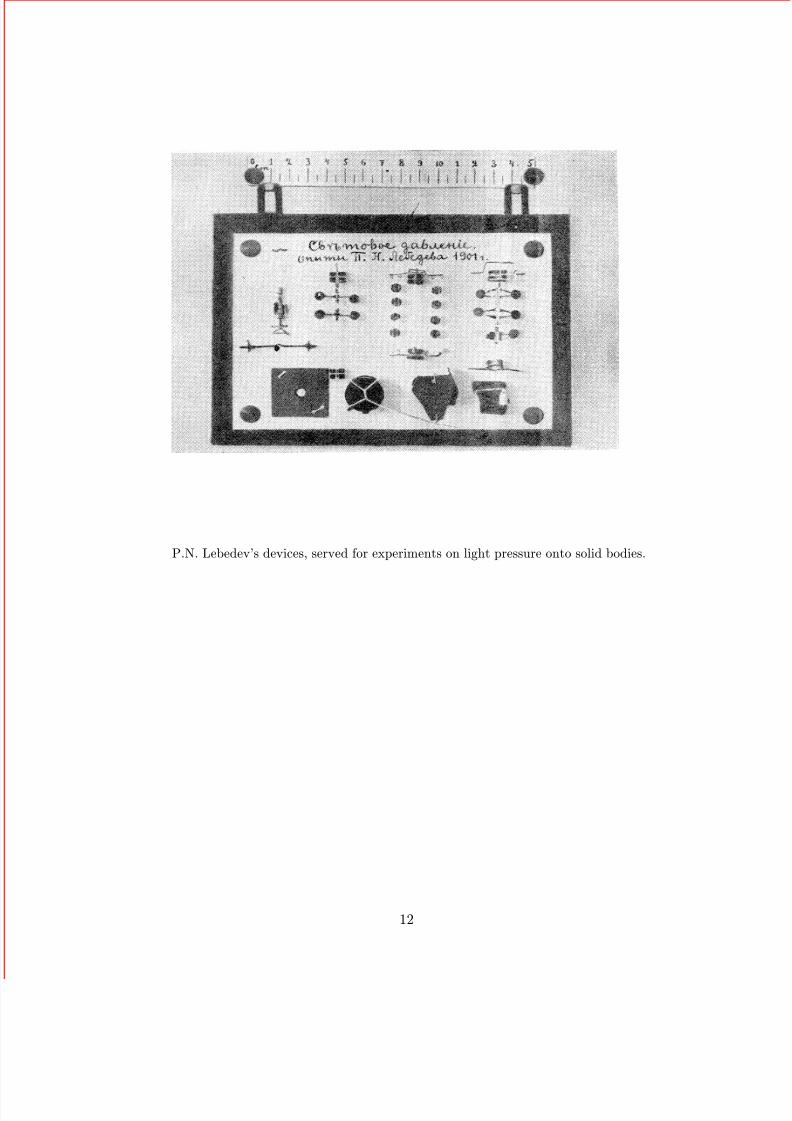
P.N. Lebedev’s devices, served for experiments on light pressure onto solid bodies.
12

8/3/2019 Experimental Examination of Light Pressure - Annalen Der Physik - Pyotr Lebedev - 1901 - English
http://slidepdf.com/reader/full/experimental-examination-of-light-pressure-annalen-der-physik-pyotr-lebedev 13/26
Figure 7:
Calorimeter I (fig. 6) consisted of a piece of copper, in which the verticalchannel charged with quicksilver was drilled. The blob of the very smallcalorimeter thermometer devided by the fifth shares of degree was positionedin quicksilver. The immersing surface of a calorimeter was smoked. Thecalculated general calorimeter capacity of the device (figuring specific heatcapacity of copper = 0,093) was equaled to 3,13 g of water.
Calorimeter II (fig. 8) was presented by the copper bulb, as well as thefirst calorimeter, with general thermal capacity equal to 3,61 g of water; itsimmersing surface was beforehand gilt, and then it was galvanically coveredby platinum niello; this bulb was put into a copper tube located inside awater bath, about one litre in volume; the bath was supplied with an agitatorR. To cool the calorimeter below the bath temperature, prior to begin theexperiment, some drops of an etil ether were inlet through a glass tube A
into a conical dimple of a calorimeter and then, through rubber fur B, airwas banished which carried away with itself vapours of a volatilizing ether.
The measurements have shown, that from 1,2 up to 1,8 g · cal impingesin a minute on the diaphragm (d = 5 mm), i.e. that in my experiments the
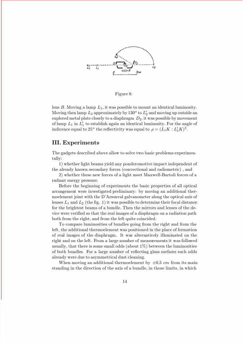
luminosity of irradiating was from two to three times higher than the energyof solar beams at a ground surface .To determine the reflectivity of explored metals the Ritchie photometer
(fig. 9) served. The light from two small incandescent lamps L1 and L2
impinged, transiting diaphragms D1 and D2 (diameter = 3 mm), onto asmall prism K made of chalk , and the edge of the last one was observed by
13
8/3/2019 Experimental Examination of Light Pressure - Annalen Der Physik - Pyotr Lebedev - 1901 - English
http://slidepdf.com/reader/full/experimental-examination-of-light-pressure-annalen-der-physik-pyotr-lebedev 14/26
Figure 8:
lens B. Moving a lamp L1, it was possible to mount an identical luminosity.Moving then lamp L2 approximately by 130o to L
2and moving up outside an
explored metal plate closely to a diaphragm D2, it was possible by movementof lamp L1 in L
1to establish again an identical luminosity. For the angle of
indicence equal to 25o the reflectivity was equal to ρ = (L1K : L
1K )2.
III. Experiments
The gadgets described above allow to solve two basic problems experimen-tally:
1) whether light beams yield any ponderomotive impact independent of the already known secondary forces (convectional and radiometric) , and
2) whether these new forces of a light meet Maxwell-Bartoli forces of a
radiant energy pressure.Before the beginning of experiments the basic properties of all optical
arrangement were investigated preliminary: by moving an additional ther-moelement joint with the D’Arsonval galvanometer along the optical axis of lenses L1 and L2 (the fig. 1) it was possible to determine their focal distancefor the brightest beams of a bundle. Then the mirrors and lenses of the de-vice were verified so that the real images of a diaphragm on a radiation pathboth from the right, and from the left quite coincided.
To compare luminosities of bundles going from the right and from theleft, the additional thermoelement was positioned in the place of formationof real images of the diaphragm. It was alternatively illuminated on the
right and on the left. From a large number of measurements it was followedusually, that there is some small odds (about 1%) between the luminositiesof both bundles. For a large number of reflecting glass surfaces such oddsalready were due to asymmetrical dust cleaning.
When moving an additional thermoelement by ±0,5 cm from its mainstanding in the direction of the axis of a bundle, in those limits, in which
14

8/3/2019 Experimental Examination of Light Pressure - Annalen Der Physik - Pyotr Lebedev - 1901 - English
http://slidepdf.com/reader/full/experimental-examination-of-light-pressure-annalen-der-physik-pyotr-lebedev 15/26
the installations of a bundle on a winglet could be varied, the diminution of
luminosity by 5 % was observed for both directions of irradiating.These preliminary trials were absolutely necessary.The devices with winglets were always so located inside a bulb, that the
beams of a radiant source missed the winglet, reflected and again assembledby a concave wall of a bulb, did not impinge on parts of the suspendeddevice.
After the device with winglets was positioned into a bulb, the pumpingout began, proceeding some days and last pumpings out were yielded atwarming up of a bulb walls and at simultaneous irradiating of separatewinglets by a light of an arc. Before each series of observations the lowerpart of a bulb, where there was a drop of quicksilver, was heated in water
bath by 5oC above the room temperature, 1 then during from one till twohours the pumping out was again yielded, then the pressure lock V rose,and the cooling by dressed ice and salt followed.
In providing measurements the most essential noises were convectionalcurrents; they have an effect in a continuous course of zero, and both speed,and direction of this course depended on casual conditions (even for the samewinglet per different days of observation). During one series of observationsindicated course of zero happened ordinarily so inappreciable, that, incre-menting number of separate observations, it was easy for eliminating. Thisconvection of the heels of mercury vapours was stipulated by heating up of an illuminated winglet, and also casual exterior nonuniform heating up of
walls of a bulb and in particular by inevitable odds of temperatures of twocooled mercury surfaces. At observations without cooling oscillations stipu-lated by a convection had an effect much more abruptly, than at cooling byice with salt; at higher air pressures the observations were so inconvenient,due to a convection, that the measurements occured hardly possible.
Another reason calling oscillations of readout was the instability of avoltaic arc, which had an effect even for the best carbons. 1 The jumpsin luminosity of an arc had an effect in changes (magnification or diminu-tion) of separate vibration amplitudes of the device; they were possible foreliminating only by magnification of number of separate observations.
By means of two pipes the observer could alternately digitize deviations
1At the indicated small odds of temperatures quicksilver is not besieged on more coldwalls of the device; this appearance having place, at unwettable surfaces, was indicatedby M. C a n t o r Wied. Ann. 56, 493 (1895).
1quite satisfactory there were Simmens carbons “A”; with cheaper carbons observationsare hardly possible.
15

8/3/2019 Experimental Examination of Light Pressure - Annalen Der Physik - Pyotr Lebedev - 1901 - English
http://slidepdf.com/reader/full/experimental-examination-of-light-pressure-annalen-der-physik-pyotr-lebedev 16/26
of the device with winglets and the galvanometer. An assistant, 2 observing
for exact burning of an arc, translocated a double mirror S 1S 4 (fig. 1) on acommand. Making irradiatings with periodic interruptions, it is possible toreduce a vibration amplitude of the device to the necessary value.
The table I shows a beginning of one of the protocols of observations.
Table I.
Device III. A platinized winglet (2).Distance of centre of a circle from a rotation axis = 9 , 2 mm.
Cooling by ice with salt.Distance up to a scale A = 1195 divisions of a scale.
L1 L2 L1 L2
Calculated Calculated Calculated Calculated306 115 307 174
176 240 206 295 184 245 210 244239 302 118 207 244 303 177 211
177 239 208 296 184 243 212 245240 302 124 209 243 300 180 213
178 294 189240 208 244 212Deviation 32 divisions 36 divisions 32 divisionsG1 G2 G1 G2
308 314305 201 312 201
312 314314 316310 314
Galvanometer 109 divisions, 113 дел. скал., 113 divisionsDeviation reduced:(G = 100) 29,3 divisions, 31,8 divisions, 28,2 divisions
Notations of this table are:
L1 and L2 are rotation points on a scale, when the light have impingedon a winglet of the device from a lens L1 or from a lens L2. A medialseries, “evaluations ”, shows the standing of equilibrium calculated (fromthree adjacent rotation points). “ Deviation ” means a deviation of system
at a veering of irradiating.G1 and G2 give standings of the galvanometer in the first and second
cases (in the second case it is the origin).
2my assistant at these experiments was the preparator assistant at a study AvtonomFedorov; his diligent attitude and dexterous treatment with devices was appreciably facil-itated to me these uneasy observations.
16

8/3/2019 Experimental Examination of Light Pressure - Annalen Der Physik - Pyotr Lebedev - 1901 - English
http://slidepdf.com/reader/full/experimental-examination-of-light-pressure-annalen-der-physik-pyotr-lebedev 17/26
“Galvanometer” give deviations of the galvanometer.
”Deviations reduced (G = 100)” give the above deviations of the device,reduced to a constant deviation of the galvanometer of 100 divisions of ascale.
By an expedient indicated in Table I it was yielded seven ordinary read-outs for L1 and L2 and the medium value was derived from ”of Deviationsreduced (G = 100)” with a medial ± deviations of separate observations.(For a winglet of the table I this double deviation was a = 29, 4 ± 1, 6 of scale divisions.)
To compare observations made with different winglets the following ad-ditional corrections were necessary.
In Devices I and III the narrow band of light impinges, apart from the
circle, on the parts, supporting it, due to that the deviation is incremented;by measuring the areas of enlighten parts and their distance from a rotationaxis we can subtract that additional impact, which they yield (from 5 % upto 10 % of the total quantity), and we gain that deviation, which is stipulatedby a circle of a winglet only (device II is free from this correction). For awinglet of Table I this correction makes 1,9 divisions of scale; the calculateddouble deviation is 27,5 divisions of scale.
The measurement of distances from the circle centre of a winglet to arotation axis was yielded by the following expedient: the arc lantern withthe reflecting device was removed by slides, and from the side of beams,impinging during experiment, the plumb-line made of a thin brilliant silver
wire was hung up as close as possible to the bulb; the visual pipe withan ocular micrometer was placed perpendicularly to a plane of disks at adistance about 4 meters, and it was necessary to translocate a plumb-lineuntil then, it did not cover with itself a rotating hairline. The quantityrelevant to one division of an ocular micrometer of a pipe, was determinedwith the help of sighting a scale located at hand of a bulb; an apparentdistance of a circle centre of a winglet from a plumb-line gave true distancefrom the first one to the torsion axis and could be measured to within
±0, 5 mm; the measured distances laid between 9 and 11 mm.On the basis of these measurements the observed double deviations were
given in deviations relevant to distance of centres of circles from a rotation
axis, equal to 1 cm. For a winglet of Table I such reduced deviation wasequal to 29,9 divisions of scale.
To determine an absolute value of light pressure occured on a winglet, itwas necessary to measure an absolute value of the guiding force of a rotatinghairline. Instead of the device with winglets a body (copper bulb) with aknown moment of inertia was suspended to a hook of a rotating hairline, and
17

8/3/2019 Experimental Examination of Light Pressure - Annalen Der Physik - Pyotr Lebedev - 1901 - English
http://slidepdf.com/reader/full/experimental-examination-of-light-pressure-annalen-der-physik-pyotr-lebedev 18/26
from three series of observations, of which everyone consisted of ten prime
rockings, the medial time of one rocking was derived. 1
Table II.
Time of a prime rockingCopper bulb
One mirror and t1
2= 5, 1 ± 0, 05 sec. Length = 4, 0 cm
Mirror + copper bulbt2
2= 29, 4 ± 0, 1 sec. Mass = 0, 314 g
Guiding force D = 0, 00494 dynes · cm
On the basis of the indicated value of guiding force we gain for a winglet
of Table I under unilateral irradiating the value of a light pressure in dynes:
ρ = 0, 0000308 dyn ± 0, 0000017 dyn
To test calculations of Maxwell and Bartoli, it is necessary to estimatethe value of light pressure, which is necessary to expect at experiments ac-cording to the evocative theory, and to compare the calculated value withthe observed. For this purpose it is necessary to make a calorimeter mea-surement of impinging light energy, and also a photometer measurement of reflectivities of the winglets.
The measurements made with the help of the first calorimeter (fig. 6)were yielded as follows: the mirrors (fig. 1) were tapped aside by slidesso, that it was possible to put a diaphragm of a calorimeter D in the placeof devices with winglets. Then the calorimeter was illuminated within 5minutes, and every minute the observations of the thermometer (togetherwith galvanometer) were made. After that the irradiating was interruptedby means of the opaque screen, and in the following 5 minutes the observa-tions of the thermometer, which now gradually diminished, were made everyminute again, and the origin of a galvanometer was observed. A completeseries of observations implied five sequential periods of irradiating.
All observations were handled pictorially, for that purpose the obser-vations of the thermometer were superimposed on a coordinate paper andwere joined by a continuous curve so that the last one flowed as smooth aspossible (fig. 10). It is clear from the figure that the course of temperaturein 10 seconds discovers a transition from irradiating to a blackout or backby a singular revolution point.
1compare: F. K o h l r a u s c h, Lehrbuch der praktischen Physik, § 29 and comment11 and 12. Teubner, Leipzig 1901.
18

8/3/2019 Experimental Examination of Light Pressure - Annalen Der Physik - Pyotr Lebedev - 1901 - English
http://slidepdf.com/reader/full/experimental-examination-of-light-pressure-annalen-der-physik-pyotr-lebedev 19/26
Figure 9:
The very high velocity of a calorimeter cooling entails necessity of thespecial handling of results, as even during one interval of observation neithervelocity of heating up, nor velocity of cooling are not constant values. Fora definite medial temperature of a surface of a calorimeter both velocitieshave constant values represented by tangential lines (the last ones are easilysuperimposed on the delineation). For these constant values the intersectionpoints of tangential lines with ordinates, restricting the interval, gave thosetemperature differences, which would be established in 5 minutes, if both ve-locities were constant. The sum of two differences gives a general, correctedby losses, rise of a calorimeter temperature.
But here a source of errors in determination of true medial temperatureof a surface appears; the thermometer has not enough time to follow thetemperature and it gives at irradiating too low, and at cooling too high ob-servations. That circumstance, that the thermometer discovers a revolutionpoint in 10 sec., allows, as a first and for our experiments a sufficient ap-proximation, to suppose, that the thermometer lags behind on 20 sec. Thenfor the medial temperature it is necessary to compare not the points of acurve t1 and t2, but points T 1 and T 2, laying on the same curve by 20 sec.
earlier.Such pictorial definitions were done at each heating up for two temper-
atures; Table III represents one series of measurements.
19

8/3/2019 Experimental Examination of Light Pressure - Annalen Der Physik - Pyotr Lebedev - 1901 - English
http://slidepdf.com/reader/full/experimental-examination-of-light-pressure-annalen-der-physik-pyotr-lebedev 20/26
Table III.
Calorimeter I. A water equivalent = 3,13 g
Deviation ReducedVelocity Velocity General Galvanometer Generalof Heating of Cooling Heating Heating
(G = 100)
I
1o, 571, 49
0o, 630, 80
2o, 302, 29
140 div.
128 ”1o, 641, 79
II
1, 441, 31
0, 851, 10
2, 292, 40
128 ”122 ”
1, 791, 97
III
1, 381, 00
1, 081, 37
2, 462, 37
129 ”126 ”
1, 911, 88
IV 1, 30
1, 04
1, 15
1, 45
2, 45
2, 49
123 ”
127 ”
1, 99
1, 96
V
1, 260, 93
1, 271, 50
2, 542, 43
129 ”126 ”
1, 971, 93
General heating up in 5 min. (G = 100) 1o, 88 ± 0o, 09.
With the second calorimeter (fig. 8) the measurements were much easier:the calorimeter was cooled (by 2, 5o below the bath temperature) with thehelp of an ethyl ether, then exposed to heating up by beams, and the observerin each minute digitized the observation of the calorimeter thermometer(and in gaps — a deviation of the galvanometer and the temperature of a water bath). The observations were superimposed pictorially, joined by
a continuous curve; on this curve the bath temperature was scored, 1 andat this point a tangential line was carried out to a curve relevant to thetrue velocity of heating up of a calorimeter, irrespective of losses through aradiation. If to take two points of a curve relevant to time 2,5 min. beforeand later the equality of temperatures, we also receive a medial velocityof heating up of a calorimeter during 5 min. Table IV gives the results of observations. 2
1Again it is necessary to have in mind that the calorimeter thermometer is in delayfrom the true temperature of a calorimeter by 20 sec.
2Results of Tables III and IV can not serve for immediate comparison, as they concernto different adjustments of a thermopile.
20

8/3/2019 Experimental Examination of Light Pressure - Annalen Der Physik - Pyotr Lebedev - 1901 - English
http://slidepdf.com/reader/full/experimental-examination-of-light-pressure-annalen-der-physik-pyotr-lebedev 21/26
T a b l e I V .
C a l o r i m e t e r I I . G e n e r a l c a l o r i m e t e r c a p a c i t y =
3 , 6 1
g o f w a t e r .
H e a t i n
g u p i n
5 m
i n .
S e r i e s
M e d i u m s
D e v i a t i o n
H e a t i n g u p ,
o f
f r o m
f r o m
o f
t a n g e n t i o n a l
d i ff e r e n c e s
g a l v a n o m e t e r
r e d u c e d
o b s e r v a t i o n s
l i n e
o f t e m p e r a t u r e s
t o G
= 1 0
0
d i v i s i o n s o f s c a l e
I
2 o , 4 0
2 o , 4 1
2 o , 4 0
1 5 9 d i v i s i o n s o f s c a l e
1 o , 5 1
I I
2 o , 5 5
2 o 5 7
2 o , 5
7
1 6 3
”
”
1 o , 5
7
I I I
2 o , 4 3
2 o , 5 0
2 o , 4 6
1 5 8
”
”
1 o , 5 6
M e d i a l h e a t i n g
u p ( f o r G
= 1 0 0 ) 1 o , 5 5 ±
O o , 0 2 ,
From here we obtain the value of energy, impinging within second:
=1, 55 · 3, 61 · 4, 18 · 107
300ergs = 7, 74 · 105 ergs
At our experiments the beams impinged not as parallel, but as a conver-gent bundle; their declination was, however, so inappreciable, that a correc-
21

8/3/2019 Experimental Examination of Light Pressure - Annalen Der Physik - Pyotr Lebedev - 1901 - English
http://slidepdf.com/reader/full/experimental-examination-of-light-pressure-annalen-der-physik-pyotr-lebedev 22/26
tion stipulated by it 3 (about 1 %) could be dropped in view of other much
larger inaccuracies of observations. We can, hence, make calculations ac-cording to the formulas, given by Maxwell and Bartoli for a parallel bundle.
For the absolute black body we gain on the basis of calorimeter mea-surements of Table IV a value of pressure p:
(in dynes) =E (in ergs)
3 · 1010= 0, 0000258 dynes
To express the results obtained in conveniently comparable quantities,we shall take as a unit of comparison the value of Maxwell-Bartoli pressurerefered to the absolute black body , calculated from calorimeter observations,and we shall term this arbitrary unit as MB unit.
In these units the results of Table I will be expressed as follows:
p =0, 0000308 ± 0, 0000017
0, 0000253= (1, 19 ± 0, 07) MB.
The straightforward measurement of reflectivities of explored wingletswas impossible, because their surfaces have appeared too rough. ThereforeI have spotted through a photometer (fig. 9) reflectivities of those metalleafs, of which the winglets were made; irregularities of these leafs also hada substantial effect and, besides, the clearly expressed colouring of a reflectedlight (especially for nickel); the values of these reflectivities measured for anangle of indicence 25 o, are given in Table V without further reductions. Forthe comparison reflectivities here are also indicated for a normal slope of beams (λ = 600 µµ) according to Hagen and Rubens, 1 and on their basisthe Maxwell-Bartoli forces are calculated (figures obtained for magnaliumare given for aluminium).
Table V.
Photometer measurings by Hagen and Rubensρ ρ ρ ρ
Platinum ..... 0,5 ± 0,05 1,5 МВ 0,64 1,64 MBAluminium ... 0,6 ± 0,05 1,6 ” 0,83 1,83 ”Nickel ...... 0,35 ± 0,05 1,4 ” 0,65 1,65 ”
I do not give evaluations for mica , as the observations were made onlywith one winglet, and there are no test measurements with thicker winglets.
3see L. B o l t z m a n n, Wied. Ann. 22, 292 (1884), and also D. H o l d h a m m er, cit. above, page 844.
1H. H a g e n and R u b e n s, Ann. d. Phys. 1, 373 (1900).
22
8/3/2019 Experimental Examination of Light Pressure - Annalen Der Physik - Pyotr Lebedev - 1901 - English
http://slidepdf.com/reader/full/experimental-examination-of-light-pressure-annalen-der-physik-pyotr-lebedev 23/26
The results of a separate series of observations made by me with different
devices are presented below. When I had transfered from observations atroom temperature, at which the inevitable oscillations of final outputs arerather significant, to measurements with cooling by ice with salt, I did notexpect to receive such consent between the observed quantities and thosecalculated according to Maxwell - Bartoli, which streamed from my exper-iments; I therefore have assumed, that such coincidence of evaluations andobservations is necessary to assign to accidents, and consequently at first hasexchanged I calorimeter by II calorimeter, and then II device with wingletsby III device.
The numerous observations, which I made with I device at a room tem-perature, were not so good as the subsequent measurements, and therefore
they were not given by me here. The observations with a platinized winglet(2) of II device were not given also, as at the microscopic examination of a winglet, which had followed the experiments, it was found, that the plat-inum niello had subsided unsatisfactorily as a sponge (that was not observedon other winglets). With III device, unfortunately, only two series of obser-vations were made, as the further experiments were interrupted by breakageof the kettle.
23

8/3/2019 Experimental Examination of Light Pressure - Annalen Der Physik - Pyotr Lebedev - 1901 - English
http://slidepdf.com/reader/full/experimental-examination-of-light-pressure-annalen-der-physik-pyotr-lebedev 24/26
T a b l e V I .
I I d e v i c e
I I I d e v i c e
I c a l o r i m e t e r
I I c a l o r i m e t e r
I
W h i t e
R e d
W
h i t e
D a r k b l u e
d e v i c e
W h i t e l i g h t
l i g h t
l i g h t
l i g h t
l i g h t
W h i t e l i g h t
1 . T h i c k - p l a t i n i z e d
1 , 8
1 , 6
1 , 5
—
—
—
—
—
1 , 5
1 , 4
w i n g l e t . . . . . .
± 0 , 2
± 0 , 1
± 0 , 1
—
—
—
—
—
± 0 , 1
± 0 , 1
2 . T h i n - p l a t i n i z e d
1 , 3
—
—
—
—
—
—
—
1 , 2
1 , 1
w i n g l e t . . . . . .
± 0 , 2
—
—
—
—
—
—
—
± 0 , 1
± 0 , 1
c a l c u l a t e d . . . . . .
. . . .
1 , 2
—
—
—
—
—
—
—
1 , 1
1 , 0
3 . P l a t i n u m t h i c k . . . . .
—
1 , 8
—
—
—
—
—
—
—
—
± 0 , 1
4 .
”
t h i n . . .
. . .
—
2 , 0
± 0 , 1
1 , 9
± 0 , 2
1 , 8
± 0 , 1
1 , 9
± 0 , 1
1 , 8
± 0 , 1
1 , 7
±
0 , 1
1 , 5
± 0
,
5
1 , 7
± 0 , 2
2 , 0 ± 0
,
1
5 . A l u m i n i u m t h i c k . . .
—
—
2 , 3
1 , 9
—
—
—
—
—
—
± 0 , 4
± 0 , 1
6 .
”
t h i n . .
. .
—
—
2 , 0
± 0 , 1
2 , 3
± 0 , 1
2 , 0
± 0 , 2
2 , 9
± 0 , 8
2 , 1
±
0 , 1
2 , 5
± 0
,
5
1 , 4
± 0 , 2
1 , 7 ± 0
,
1
7 . N i c k e l t h i n . . . .
—
—
1 , 7
± 0 , 3
1 , 2
± 0 , 2
1 , 4
± 0 , 1
2 , 3
± 0 , 5
1 , 4
±
0 , 2
2 , 7
± 0
,
9
—
—
8 . M i c a . . . . . . . . . . . .
—
—
—
—
—
—
—
—
0 , 0 8
0 , 1 3
± 0 , 0 5
± 0 , 0
3
24

8/3/2019 Experimental Examination of Light Pressure - Annalen Der Physik - Pyotr Lebedev - 1901 - English
http://slidepdf.com/reader/full/experimental-examination-of-light-pressure-annalen-der-physik-pyotr-lebedev 25/26
IV. The results
The results of experiments are given in terms of MB units; the medial de-viation in installations of devices is given in the same units under everyobserved quantity, whereas all deviations, smaller than 0,15 MB are desig-nated as 0,1 MB; those below 0,25 MB are designated as 0,2 MB and soon.
The following reasons could serve to get an idea about the precision of the given measurements: the deviations at installations of the device duringmeasurements were given in Table VI; the determination of an absolute valueof a pressing force of light (where measurements of the guiding force of atwisting hairline enter, and measurements of the distances from a mirror up
to a scale and the distance from the centre of a winglet up to a rotationaxis) was possible to be made with precision about ±8 %; evaluation of anabsolute value of MB unit from calorimeter measurements (which include ageneral water capacity, the pinch of temperature of a calorimeter and theattitude of the area of a diaphragm to the area of a circle of a winglet, whichwas close to unity) was possible to be made with probable precision in ±7%; the inaccuracy in definition of true value of reflectivities, probably, didnot exceed ±10 %.
Random inaccuracies of installation medial of the real image of the di-aphragm onto the winglet were added to the indicated inaccuracy of sep-arate measurements and also to the opportunity, that the radiation of a
winglet, heated by a light, was reflected from a concave surface of a bulband impinged on other parts of the suspended device, and the place of thissecondary heating up varied during one oscillation of the device. The gen-eral unbiased random error, at the circumscribed measurements with a whitelight , probably, did not exceed ±20 %.
In experiments with red and blue light, when the amount of impingingenergy was five times less, casual oscillations stipulated by a convection,were the same, and consequently, the precision of the obtained results wascorrespondingly less;it was necessary to note the same also on rather verysmall deviations (hardly reaching four divisions of a scale) at a mica winglet.These experiments, which were undertaken as test ones, nevertheless allowed
to state, that in these cases there were no new ponderomotive forces whichwould be comparable to the Maxwell-Bartoli forces in their value.
Besides, I multiply provided comparative measurements with thin andthick metal (reflecting) platinum and aluminium winglets; however, I didnot manage to detect clearly enough expressed radiometric odds; that waswhy it was possible to consider radiometric forces of thin metal winglets as
25

8/3/2019 Experimental Examination of Light Pressure - Annalen Der Physik - Pyotr Lebedev - 1901 - English
http://slidepdf.com/reader/full/experimental-examination-of-light-pressure-annalen-der-physik-pyotr-lebedev 26/26
equal to zero within limits of observational errors.
The results obtained can be stated as follows:
1) The impinging bundle of light yields pressure both on reflecting, andon absorbing surfaces; these ponderomotive forces are not connected withalready known secondary convectional and radiometric forces called by heat-ing up.
2) The forces of light pressure are directly proportional to the energy of an impinging beam and do not depend on its colour.
3) The observed forces of light pressure, within limits of observationalerrors, are quantitatively equal to the Maxwell-Bartoli forces of pressure of a radiant energy.
Thus the existence of the Maxwell-Bartoli forces of pressure has beenestablished for the light beams experimentally.
Physical laboratory of the University.
Moscow, August 1901.
26