Experimental evaluation ofextended endplate beam-to-column ... · PDF fileExperimental...
16
Estudo Geral repository of University of Coimbra Title Experimental evaluation of extended endplate beam-to-column joints subjected to bending and axial force Authors(s) Lima, L. R. O. de Publication date 2004 Publication information Engineering Structures. 26:10 (2004) 1333-1347, : Downaloaded 2018-05-15T19:45:12Z Some rights reserved. For more information, please see the item record link above.
Transcript of Experimental evaluation ofextended endplate beam-to-column ... · PDF fileExperimental...

Estudo Geral repository of University of Coimbra
Title Experimental evaluation of extended endplate beam-to-column joints subjected to bending
and axial force
Authors(s) Lima, L. R. O. de
Publication date 2004
Publication information Engineering Structures. 26:10 (2004) 1333-1347, :
Downaloaded 2018-05-15T19:45:12Z
Some rights reserved. For more information, please see the item record link above.

� Corresponding author. Tel.: +351-239
797-217.
E-mail address: [email protected] (L. Sim
0141-0296/$ - see front matter # 2004 Else
doi:10.1016/j.engstruct.2004.04.003
-797-216; fax: +351-239-
oes da Silva).
vier Ltd. All rights reserved.
Engineering Structures 26 (2004) 1333–1347
www.elsevier.com/locate/engstructExperimental evaluation of extended endplate beam-to-columnjoints subjected to bending and axial force
L.R.O. de Lima a, L. Simoes da Silva b,�, P.C.G. da S. Vellasco a, S.A.L. de Andrade a,c
a Structural Engineering Department, UERJ—State University of Rio de Janeiro, Rio de Janeiro, Brazilb Civil Engineering Department, University of Coimbra, Polo II, Pinhal de Marrocos, Coimbra 3030-290, Portugal
c Civil Engineering Department, PUC-RIO—Pontifical Catholic University of Rio de Janeiro, Rio de Janeiro, Brazil
Received 2 February 2004; accepted 13 April 2004
Abstract
Steel beam-to-column joints are often subjected to a combination of bending moment and axial force. Current specifications forsteel joints do not take into account the presence of axial forces (tension and/or compression) in the joints. A single empiricallimitation of 5% of the beam’s plastic axial capacity is the only enforced provision in Eurocode 3—Part 1.8. The objective of thepresent paper is to describe an experimental program carried out at the University of Coimbra on extended endplate beam-to-col-umn joints to try to extend the component method philosophy to the combined action of bending moment and axial force. Tofulfil this objective, a set of seven extended beam-to-column joints were tested. This paper provides a detailed description of thisexperimental programme focusing on the moment–rotation curves and individual component assessment. Finally, it reveals thatthe presence of an axial force on the beam significantly modifies the joint response.# 2004 Elsevier Ltd. All rights reserved.
Keywords: Component method; Experimental analysis; Extended endplate joints; Semi-rigid behaviour; Bending moment and axial force
1. Introduction
1.1. Generalities
Commonly, beam-to-column joints and beam splicesare subjected to a combination of bending moment andaxial force. A typical example of such situation is illu-strated in Fig. 1.
Joints subjected to combination of bending moment(M) and axial force (N) usually operate around twotypical situations:
(i) l
ow values of the M=N ratio, characteristic of col-umn base joints. In this case, all bolt rows areusually not active (in compression) and the neutralaxis often lies inside the section.(ii) h
igh values of the M=N ratio, characteristic ofbeam-to-column joints. In this case, it is commonthat during a specific loading history, there is rever-sal of bolt row forces.Currently, no specific provisions are available for theanalysis and design of beam-to-column joints underbending and axial forces in the context of part 1.8 ofEurocode 3 [1]. Historically, for the high M=N ratiorange, the revised version of Annex J [2] proposed a sin-gle empirical limitation on the allowable axial force of10% of the beam axial plastic resistance, below whichthe axial force could be disregarded in the analysis.
For column bases (low M=N ratio), specific proce-dures where developed during the late 1990s [3–5], thatare now incorporated into part 1.8 of EC3 [1]. Despitethe differences between column bases and beam-to-col-umn joints, the former already cover some aspects rel-evant to the latter case. In particular, they identify thedifferent situations corresponding to the various poss-ible positions of the neutral axis. However, columnbases miss all aspects related to the contribution of thecolumn web panel to the beam-to-column jointresponse.
Adopting the component method as the framework,this lack of guidance motivated a coordinated effortwithin the ECCS, Technical Committee 10, ‘‘Connec-

Nomenclature
K individual component stiffnessE Young’s modulusFRd individual component resistanceFRd row row component resistanceMj,Rd bending moment capacitySj,ini joint initial stiffnessr1 and r2 principal stressesrVM von Mises stress
1334 L.R.O. de Lima et al. / Engineering Structures 26 (2004) 1333–1347
tions’’ (TWG 10.2), to develop explicit rules. Thispaper briefly reviews the current developments anddescribes in detail the experimental work performed onextended endplate beam-to-column joints carried out atthe University of Coimbra, Portugal.
1.2. Experimental background
A summary of the experimental work on beam-to-column joints under combined bending momentand axial force is presented below. Guisse et al. [6]performed tests on six prototypes of column baseswith extended endplates with bolts placed outside ofthe beam height and six more tests on flush endplateswith bolts inside the beam height. Although related
to column bases, these tests provided some relevantinformation. The experimental test layout and theconfiguration of the joints are presented in Fig. 2.Two different endplate thicknesses (15 and 30 mm)were used and three levels of axial force, i.e., 100,400 and 1000 kN for first series and 100, 600 and1000 kN for second series. The compressive axialforce was applied first and kept constant during thetest while the bending moment was subsequentlyincreased up to failure.
Wald and coauthors [4] performed two tests at theTechnical University in Prague on beam-to-beam andbeam-to-column joints. The loading application systemused in these tests may be observed in Fig. 3(a) and ledto proportional increase of axial force and bending
Fig. 1. Example of a pitched-roof portal frame joint.
Fig. 2. Guisse et al.’s test information [6]. (a) Joint type and (b) experimental test layout.

L.R.O. de Lima et al. / Engineering Structures 26 (2004) 1333–1347 1335
moment. The resulting deformed configurations andmoment versus rotation curves are presented inFig. 3(b) and (c), respectively. From these two tests, itcould be concluded that the bending moment resistancein test SN1000 was greater than that in the second test,in line with the different level of applied axial force.For both tests, failure occurred at the column flange inthe compression zone. Unfortunately, no test with onlybending moment was performed, which prevented thedetermination of the influence of the axial force in thejoint response.
An experimental programme using endplatebeam-to-column joints was performed at the CivilEngineering Department of the University of Coimbra,Portugal. The test programme included 15 prototypes,i.e., eight flush endplate joints and seven extended end-plate joints. The results of the flush endplate tests maybe found in Refs. [8–10] while the extended endplatetests will be discussed in detail in this paper. The adop-ted loading strategy for the flush endplate joints con-sisted of an initial application of the total axial force(tension or compression), kept constant during the testand the subsequent incremental application of thebending moment. These tests have shown that the pres-
ence of axial force may significantly affect the jointresponse in terms of bending resistance. For low levelsof compressive axial force, an increase of the bendingresistance was observed. On the other hand, the pres-ence of tensile axial force on the joint caused immedi-ate reduction of the bending resistance due topremature yielding of the critical joint component inthe tension zone, i.e., endplate in bending. Fig. 4 showsthe deformed joints for tests FE6 (compressive axialforce of 27% of the beam plastic resistance) and FE9(tensile axial force of 20% of the beam plastic resist-ance), respectively.
1.3. Analytical models
Recently, several analytical models have been pro-posed in order to predict the behaviour of beam-to-column joints under bending and axial force. At theUniversity of Liege, Jaspart [11,12], Finet [13] and Cer-fontaine [14] have applied the principles of the compo-nent method to develop design predictions of the M–Ninteraction curves and initial stiffness.
The investigation performed in Liege proposed thatthe beam-to-column joint subjected to bending and
d moment versus rotation curves for tests performed by Wald and coauthors [4]. (a) Test layout, (
Fig. 3. Test layout an b) joint residual defor-mation and (c) beam-to-column moment versus rotation curves.
te beam-to-column joints [10]. (a) Test FE6 (N ¼ �27% Npl)—beam flange in
Fig. 4. Failure of flush endpla compression and (b) test FE9(N ¼ þ20% Npl)—endplate in bending.

1336 L.R.O. de Lima et al. / Engineering Structures 26 (2004) 1333–1347
compressive axial force may be characterized with theaid of Fig. 5, where the response of each compressivecomponent is simulated by an extensional spring whosebehaviour may be observed in Fig. 5(c).
Based on the same general principles, Silva andCoelho [15] have proposed analytical expressions forthe full non-linear response of a welded beam-to-col-umn joint under combined bending and axial force. Inthis model, each non-linear spring was replaced withtwo equivalent elastic springs using an energy formu-lation and a post-limit stability analysis. This analyticalmodel was applied to a welded joint extracted fromSERICON II database [16], but the comparison withtest results was performed without considering thepresence of the axial force.
Sokol et al. [17] proposed an analytical model to pre-dict the behaviour of joints subjected to bendingmoment and axial force for proportional loading, i.e.,the axial force and the bending moment are simul-taneously increased. This model was calibrated throughcomparison with experimental tests performed by Waldand Svarc [7].
Table 1 presents a summary of recent studies per-formed to investigate the joints behaviour subjected tobending moment and axial force.
2. Experimental programme
2.1. General description
The experimental program on extended endplatebeam-to-column joints consisted of seven tests compris-
ing several combinations of bending moment and axialforce. In all tests, the joint configuration was identical(Fig. 6), the column being simply supported at bothends and consisting of an HEB240, the beams sectionswere IPE240 and the endplate was 15 mm thick, allmanufactured from a steel S275. The bolts were M20,grade 10.9, pre-stressed with a torque of 150 Nm.
The seven tests were performed by first applying afixed level of axial tension or compression and subse-quently imposing a negative bending moment, incre-mented up to the joint failure. In the first test, EE1,only bending moment was applied. For the followingtests, EE2, EE3, EE4, EE5, EE6 and EE7, constantaxial forces of, respectively, �10%, �20%, �27%,�15%, +10% and + 20% of the beam plastic resistancewere applied to the beam.
2.2. Test setup, instrumentation and testing procedure
The test setup is illustrated in Fig. 7(a) with thebending moment being applied through a hydraulicactuator, located 1 m away from the column flangeface.
The adopted compressive axial force application sys-tem consisted of a central hydraulic jack locatedbehind the reaction wall, Fig. 7(b), that applies a ten-sile force to four pre-stressing cables with diameter/ ¼ 15:2 mm. The transfer of this force to the connec-tion was performed through a 600 kN central load cell,Fig. 7(c). These cables pass through a deviator saddle(HEM100) to guarantee that the axial force is alwaysparallel to the beam axis and 200 kN load cells were
anical model developed in Liege [14]. (a) Beam-to-column joint, (b) mechanical model and (c) compone
Fig. 5. Mech nt behaviour.Table 1
Summary of studies of joints subjected to bending and axial force
Authors (date) A
nalysis type C ountry and InstitutionFinet (1994) [13] A
nalytical model U niversity of Liege (Belgium)Jaspart (1997) [11] A
nalytical model and experimental testsCerfontaine (2001) [14] A
nalytical modelSilva and Coelho (2001) [15] A
nalytical model U niversity of Coimbra (Portugal)Simoes da Silva et al. (2001) [8] A
nalytical modelLima (2003) [10] E
xperimental testsWald and Svarc (2001) [7] E
xperimental tests P rague University (Czech Republic)Sokol et al. (2002) [17] A
nalytical model
L.R.O. de Lima et al. / Engineering Structures 26 (2004) 1333–1347 1337
used in each cable to monitor the installed cable forces,Fig. 8. The horizontal reaction forces at both ends ofthe column were transmitted to the reaction wall by: (i)a steel beam, at the top, and (ii) a reinforced concretefooting pre-stressed to the strong floor using DYWI-DAG bars and connected to the reaction wall using anHEB200, at the bottom.
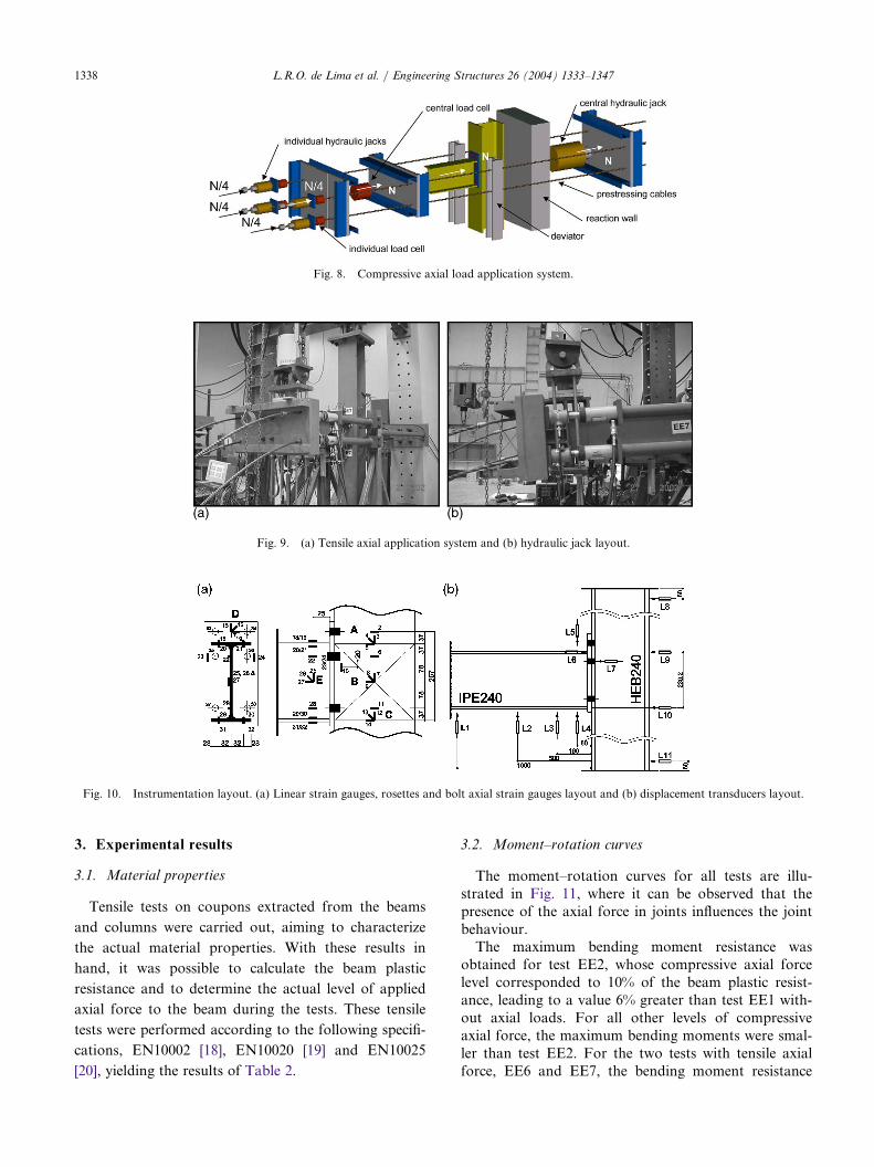
The tensile axial force application system is shown inFig. 9(a). Four hydraulic jacks located in one of theextremities of a circular hollow section profile transmitthe tensile axial force. These circular profiles are simplysupported in the other end to allow free rotation andto guarantee that the axial force is always applied par-allel to the beam axis. The hydraulic jacks are connec-ted to the same hydraulic system in order to applyequal amounts of load to the four cables, Fig. 9(b).
All tests were instrumented as depicted in Fig. 10,
with linear strain gauges (FLK 6-11-TML), rosettes at
45v
(FRA 5-11-TML), bolt axial strain gauges (BTM
6-C-TML), and displacements transducers (LVDTs).
All data were recorded with a data acquisition system
TDS602-TML.For all tests, a constant axial force was applied first,
maintained constant throughout the test, with the sub-
sequent application of a bending moment incremented
up to failure. Two unloading phases were performed.
The first, for a bending moment of 100 kN m (down to
20 kN m, to eliminate possible slack in the joint) and
the second for a rotation of 50 mrad. Force control
was used in the first part of each test, subsequently
changed to displacement control in the latter part.
Fig. 6. Extended endplate beam-to-column joint layout.
Fig. 7. (a) Compressive axial loading frame, (b) hydraulic jack and (c) central load cell.
1338 L.R.O. de Lima et al. / Engineering Structures 26 (2004) 1333–1347
3. Experimental results
3.1. Material properties
Tensile tests on coupons extracted from the beams
and columns were carried out, aiming to characterize
the actual material properties. With these results in
hand, it was possible to calculate the beam plastic
resistance and to determine the actual level of applied
axial force to the beam during the tests. These tensile
tests were performed according to the following specifi-
cations, EN10002 [18], EN10020 [19] and EN10025
[20], yielding the results of Table 2.
3.2. Moment–rotation curves
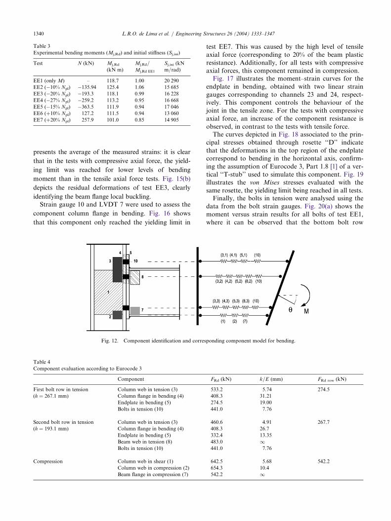
The moment–rotation curves for all tests are illu-strated in Fig. 11, where it can be observed that thepresence of the axial force in joints influences the jointbehaviour.
The maximum bending moment resistance wasobtained for test EE2, whose compressive axial forcelevel corresponded to 10% of the beam plastic resist-ance, leading to a value 6% greater than test EE1 with-out axial loads. For all other levels of compressiveaxial force, the maximum bending moments were smal-ler than test EE2. For the two tests with tensile axialforce, EE6 and EE7, the bending moment resistance
Fig. 8. Compressive axial load application system.
Fig. 9. (a) Tensile axial application system and (b) hydraulic jack layout.
tion layout. (a) Linear strain gauges, rosettes and bolt axial strain gauges layout and (b) displaceme
Fig. 10. Instrumenta nt transducers layout.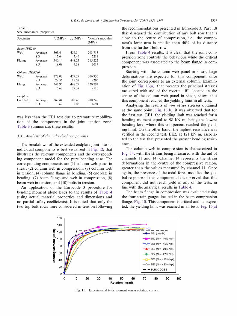
L.R.O. de Lima et al. / Engineering Structures 26 (2004) 1333–1347 1339
was less than the EE1 test due to premature mobiliza-tion of the components in the joint tension zone.Table 3 summarizes these results.
3.3. Analysis of the individual components
The breakdown of the extended endplate joint into itsindividual components is best visualized in Fig. 12, thatillustrates the relevant components and the correspond-ing component model for the pure bending case. Thecorresponding components are (1) column web panel inshear, (2) column web in compression, (3) column webin tension, (4) column flange in bending, (5) endplate inbending, (7) beam flange and web in compression, (8)beam web in tension, and (10) bolts in tension.
An application of the Eurocode 3 procedure forbending moment alone leads to the results of Table 4(using actual material properties and dimensions andno partial safety coefficients). It is noted that only thetwo top bolt rows were considered in tension following
the recommendations presented in Eurocode 3, Part 1.8that disregard the contribution of any bolt row that isclose to the centre of compression, i.e., the compo-nent’s lever arm is smaller than 40% of its distancefrom the farthest bolt row.
From Table 4 results, it is clear that the joint com-pression zone controls the behaviour while the criticalcomponent was associated to the beam flange in com-pression.
Starting with the column web panel in shear, largedeformations are expected for this component, sincethe joint corresponds to an external column. Examin-ation of Fig. 13(a), that presents the principal stressesmeasured with aid of the rosette ‘‘B’’, located in thecentre of the column web panel in shear, shows thatthis component reached the yielding limit in all tests.
Analysing the results of von Mises stresses obtainedat the same point, Fig. 13(b), it was observed that forthe first test, EE1, the yielding limit was reached for abending moment equal to 98 kN m, being the lowestbending level where this component reached the yield-ing limit. On the other hand, the highest resistance wasverified in the second test, EE2, at 121 kN m, associa-ted to the test that presented the greater bending resist-ance.
The column web in compression is characterized inFig. 14, with the strains being measured with the aid ofchannels 11 and 14. Channel 14 represents the straindeformations in the centre of the compressive region,greater than the values measured by channel 11. Onceagain, the presence of the axial force modifies the glo-bal response of this component. It is observed that thiscomponent did not reach yield in any of the tests, inline with the analytical results in Table 4.
The beam flange in compression was evaluated usingthe four strain gauges located in the beam compressionflange, Fig. 10. This component is critical and, as expec-ted, the yielding limit was reached in all tests. Fig. 15(a)
Table 2
Steel mechanical properties
Specimen
fy (MPa) f u (MPa) Young’s modulus(MPa)
Beam IPE240
Web A
verage 363.4 4 54.3 203 713SD
17.64 7.49 7214Flange A
verage 340.14 4 48.23 215 222SD
18.08 7.38 3017Column HEB240
Web A
verage 372.02 4 77.29 206 936SD
28.56 19.59 8206Flange A
verage 342.95 4 48.79 220 792SD
5.68 27.39 9516Endplate
Endplate A
verage 369.44 5 03.45 200 248SD
10.62 8.05 1694Fig. 11. Experimental tests: moment versus rotation curves.
1340 L.R.O. de Lima et al. / Engineering Structures 26 (2004) 1333–1347
presents the average of the measured strains: it is clear
that in the tests with compressive axial force, the yield-
ing limit was reached for lower levels of bending
moment than in the tensile axial force tests. Fig. 15(b)
depicts the residual deformations of test EE3, clearly
identifying the beam flange local buckling.Strain gauge 10 and LVDT 7 were used to assess the
component column flange in bending. Fig. 16 shows
that this component only reached the yielding limit in
test EE7. This was caused by the high level of tensileaxial force (corresponding to 20% of the beam plasticresistance). Additionally, for all tests with compressiveaxial forces, this component remained in compression.
Fig. 17 illustrates the moment–strain curves for theendplate in bending, obtained with two linear straingauges corresponding to channels 23 and 24, respect-ively. This component controls the behaviour of thejoint in the tensile zone. For the tests with compressiveaxial force, an increase of the component resistance isobserved, in contrast to the tests with tensile force.
The curves depicted in Fig. 18 associated to the prin-cipal stresses obtained through rosette ‘‘D’’ indicatethat the deformations in the top region of the endplatecorrespond to bending in the horizontal axis, confirm-ing the assumption of Eurocode 3, Part 1.8 [1] of a ver-tical ‘‘T-stub’’ used to simulate this component. Fig. 19illustrates the von Mises stresses evaluated with thesame rosette, the yielding limit being reached in all tests.
Finally, the bolts in tension were analysed using thedata from the bolt strain gauges. Fig. 20(a) shows themoment versus strain results for all bolts of test EE1,where it can be observed that the bottom bolt row
Table 3
Experimental bending moments (Mj,Rd) and initial stiffness (Sj,ini)
Test N
(kN) Mj,Rd(kN m)
M
M
j;Rd=j;Rd EE1
S
m
j,ini (kN/rad)
EE1 (only M)
– 118.7 1 .00 2 0 290EE2 (�10% Npl) �
135.94 125.4 1 .06 1 5 685EE3 (�20% Npl) �
193.3 118.1 0 .99 1 6 228EE4 (�27% Npl) �
259.2 113.2 0 .95 1 6 668EE5 (�15% Npl) �
363.5 111.9 0 .94 1 7 046EE6 (+10% Npl)
127.2 111.5 0 .94 1 3 060EE7 (+20% Npl)
257.9 101.0 0 .85 1 4 905Fig. 12. Component identification and corresponding component model for bending.
Table 4
Component evaluation according to Eurocode 3
C
omponent FRd (kN) k =E (mm) FRd row (kN)First bolt row in tension
(h ¼ 267:1 mm)
C
C
olumn web in tension (3)
533.2 5.74 274.5olumn flange in bending (4)
408.3 3 1.21Endplate in bending (5)
274.5 1 9.00Bolts in tension (10)
441.0 7.76Second bolt row in tension
(h ¼ 193:1 mm)
C
C
olumn web in tension (3)
460.6 4.91 267.7olumn flange in bending (4)
408.3 2 6.7Endplate in bending (5)
332.4 1 3.35Beam web in tension (8)
483.0 1 Bolts in tension (10) 441.0 7.76Compression C
olumn web in shear (1) 642.5 5.68 542.2Column web in compression (2)
654.3 1 0.4Beam flange in compression (7)
542.2 1
L.R.O. de Lima et al. / Engineering Structures 26 (2004) 1333–1347 1341
. 13. Column web in shear (1)—moment versus stress curves. (a) r1 and r2, and (b) rVM
Fig .web in compression (2)—moment versus strain curves. (a) Strain gauge number 11 and (b) channe
Fig. 14. Column l 14 of rosette C.ompression (7)—moment versus strain curves. (a) Average of measured strains (strain ga
Fig. 15. Beam flange in c uges 29–32) and (b) beamflange and web in compression residual deformation.

1342 L.R.O. de Lima et al. / Engineering Structures 26 (2004) 1333–1347
bending (4)—moment versus strain and moment versus displacement curves. (a) Strai
Fig. 16. Column flange in n gauge number 10 and (b)LVDT 7 measured displacements.
te in bending (5)—moment versus strain curves. (a) Strain gauge number 23 and (b) strain ga
Fig. 17. Endpla uge number 24.bending (5)—moment versus principal stresses curves. (a) Principal stresses—r1 and (b) p
Fig. 18. Endplate in rincipal stresses—r2.
L.R.O. de Lima et al. / Engineering Structures 26 (2004) 1333–1347 1343
remained in compression, thus validating the hypoth-
esis that this bolt row did not contribute to the joint
bending resistance. In this test, prying forces were
observed, Fig. 20(b). This figure shows a comparison
between the hydraulic actuator applied force and the
measured force in the top four bolts.Fig. 21 depicts the moment versus strain results for
one of the compressive axial force tests, EE4. In this
(5)—moment versus von Mises stresses curves. (a) von Mises stresses and (b) endplate
Fig. 19. Endplate in bending in bending residual deforma-tions.
Fig. 20. Bolts in tension (10)—moment versus strain curves (EE1 test).
Fig. 21. Bolts in tension (10)—moment versus strain curves (EE4 test).

1344 L.R.O. de Lima et al. / Engineering Structures 26 (2004) 1333–1347
Fig. 22. Bolts in tension (10)—moment versus strain curves (EE7 test).
Fig. 23. Yielding sequence of the components.

L.R.O. de Lima et al. / Engineering Structures 26 (2004) 1333–1347 1345
case, the presence of the axial force decreases the bolt
load maintaining the applied bottom bolt forces in
compression.Test EE7 did not exhibit prying forces because of
premature separation between the endplate and the
beam flange upon application of the tensile axial force.
This is illustrated in Fig. 22.Fig. 23 summarizes, for each test, the sequence of
yielding for all components. It clearly shows that, as
noted before, with increasing compressive force, the
beam flange in compression becomes progressively
more critical. Analogously, with increasing tension
forces, the endplate in bending becomes the critical
component.
3.4. Interaction diagrams
The results of Fig. 23 can be condensed in an M–N
interaction diagram that illustrates the variation of
yielding of each component, shown in Fig. 24.
Fig. 25 illustrates the M–N interaction diagram cor-responding to: (i) the elastic resistance of the joint(taken as yielding of the first component); (ii) the plas-tic resistance, taken, either as (ii.1) the moment corre-sponding to a secant stiffness of Sj;ini=2, or (ii.2) asecant stiffness of Sj;ini=3 [21], and (iii) the maximum
resistance. Unfortunately, collapse was never reachedduring the tests.
4. Conclusions
This paper presented an experimental programme onextended endplate beam-to-column joints under bend-ing and axial force (tension/compression) carried outat the University of Coimbra, Portugal. The main con-clusions of this investigation were:
(i) T
he moment–rotation curves for all tests indicatethat the presence of the axial force significantlyaffects the joint structural behaviour. Themaximum bending moment resistance was obtainedFig. 24. M–N interaction diagram for each individual component.
Fig. 25. M–N interaction diagram.
1346 L.R.O. de Lima et al. / Engineering Structures 26 (2004) 1333–1347
in test EE2 whose compressive axial force levelcorresponded to 10% of the beam plastic resist-ance, a value 6% greater than test EE1 (withoutany axial load). In contrast, in the two tests withtensile axial forces, EE6 and EE7, the bendingmoment resistance was less than test EE1 due tothe premature mobilization of the joint tensionzone components.
(ii) I
t was also verified that the compression zone criti-cal component was the beam flange in compressionwhile for the tension zone, the critical componentwas the endplate in bending, results already pre-dicted using the specifications of part 1.8 of EC3.The use of component models to estimate themoment versus rotation/axial force–displacementresponse of beam-to-column joints subjected to bend-ing moment and axial force is not a straightforwardextension of similar models (see Fig. 13) developedonly for bending.
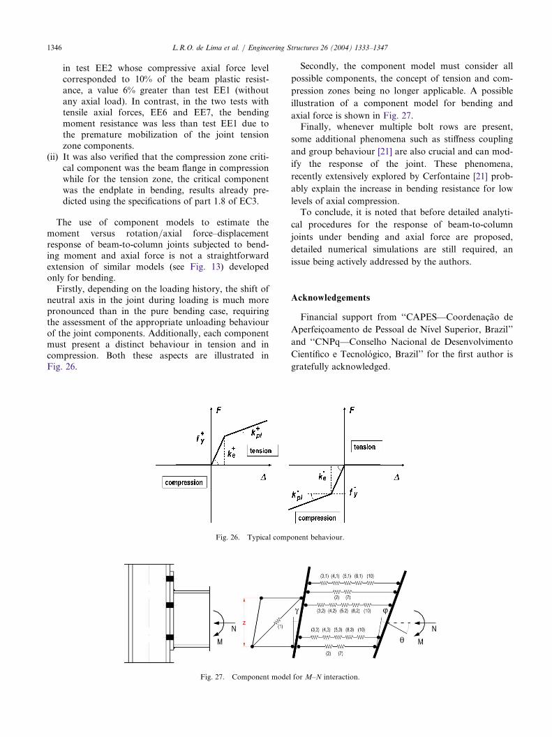
Firstly, depending on the loading history, the shift ofneutral axis in the joint during loading is much morepronounced than in the pure bending case, requiringthe assessment of the appropriate unloading behaviourof the joint components. Additionally, each componentmust present a distinct behaviour in tension and incompression. Both these aspects are illustrated inFig. 26.
Secondly, the component model must consider all
possible components, the concept of tension and com-
pression zones being no longer applicable. A possible
illustration of a component model for bending and
axial force is shown in Fig. 27.Finally, whenever multiple bolt rows are present,
some additional phenomena such as stiffness coupling
and group behaviour [21] are also crucial and can mod-
ify the response of the joint. These phenomena,
recently extensively explored by Cerfontaine [21] prob-
ably explain the increase in bending resistance for low
levels of axial compression.To conclude, it is noted that before detailed analyti-
cal procedures for the response of beam-to-column
joints under bending and axial force are proposed,
detailed numerical simulations are still required, an
issue being actively addressed by the authors.
Acknowledgements
Financial support from ‘‘CAPES—Coordenacao de
Aperfeicoamento de Pessoal de Nıvel Superior, Brazil’’
and ‘‘CNPq—Conselho Nacional de Desenvolvimento
Cientıfico e Tecnologico, Brazil’’ for the first author is
gratefully acknowledged.
Fig. 26. Typical component behaviour.
Fig. 27. Component model for M–N interaction.

L.R.O. de Lima et al. / Engineering Structures 26 (2004) 1333–1347 1347
References
[1] Eurocode 3. prEN 1993-1-8: 2003, Part 1.8: design of joints, Euro-
code 3: design of steel structures, Stage 49 draft., 5 May 2003.
Brussels: CEN, European Committee for Standardisation; 2003.
[2] Eurocode 3. ENV—1993-1-1:1992/A2, Annex J, design of steel
structures—joints in building frames. Document CEN/TC 250/SC
3. Brussels: CEN, European Committee for Standardisation; 1998.
[3] Wald F, Jaspart JP. Stiffness design of column bases. Journal of
Constructional Steel Research 1998;46(1–3):245 [paper no. 135].
[4] Pertold J, Xiao RY, Wald F. Embedded steel column bases I.
Experiments and numerical simulation. Journal of Construc-
tional Steel Research 2000;56:253–70.
[5] Pertold J, Xiao RY, Wald F. Embedded steel column bases II.
Design model proposal. Journal of Constructional Steel
Research 2000;56:271–86.
[6] Guisse S, Vandegans D, Jaspart J-P. Application of the compo-
nent method to column bases. Experimentation and develop-
ment of a mechanical model for characterization. Rapport
CRIF, MT 295. CRIF, Liege, 1997.
[7] Wald F, Svarc M. Experiments with end plate joints subject to
moment and normal force. Contributions to experimental inves-
tigation of engineering materials and structures. CTU Reports
No.: 2–3, Prague, 2001. p. 1–13.
[8] Simoes da Silva L, Lima L, Vellasco P, Andrade S. Proceedings
of the First International Conference on Steel and Composite
Structures, Pusan, 2001. Experimental and numerical assessment
of beam-to-column joints under bending and axial force, vol. 1.
Seoul: Techno Press; 2001, p. 715–22.
[9] Simoes da Silva L, Lima L, Vellasco P, Andrade S. Behaviour of
flush end-plate beam-to-column joints under bending and axial
force. Steel and Composite Structures 2004;4(2):77–94.
[10] Lima L. Behaviour of endplate beam-to-column joints under
bending and axial force. Ph.D. Thesis. PUC-Rio, Pontifical
Catholic University, Civil Engineering Department, Rio de
Janeiro, Brazil, 2003 [in Portuguese].
[11] Jaspart J-P. Recent advances in the field of steel joints. Column
bases and further configurations for beam-to-column joints and
beam splices. Department MSM, University of Liege; 1997.
[12] Jaspart J-P. General report: session on connections. Journal of
Constructional Steel Research 2000;55:69–89.
[13] Finet L. Influence de l’effort normal sur le calcul des assemblages
semi-rigides. CUST, Clermont-Ferrand. Travail de Fin d’Etudes,
CRIF, Liege, 1994 [in French].
[14] Cerfontaine F. Etude analytique de l’interaction entre moment
de flexion et effort normal dans les assemblages boulonnes. Con-
struction Metalique 2001;4:1–25 [in french].
[15] Silva LS, Coelho AG. An analytical evaluation of the response
of steel joints under bending and axial force. Computers and
Structures 2001;79:873–81.
[16] Cruz PJS, Simoes da Silva L, Rodrigues DS, Simoes RAD.
Database for the semi-rigid behaviour of beam-to-column con-
nections in seismic regions. Journal of Constructional Steel
Research 1998;46(1–3):paper no. 120.
[17] Sokol Z, Wald F, Delabre V, Muzeau JP, Svarc M. Design of
end plate joints subject to moment and normal force. Proceed-
ings of the Third European Conference on Steel Structures—
Eurosteel 2002, Coimbra 2002. Coimbra: Cmm Press; 2002,
p. 1219–28.
[18] EN 10002. Metallic materials—tensile tests. Part 1: Method of
test (at ambient temperature). Brussels: CEN, European Com-
mittee for Standardisation; 1990.
[19] EN 10020. Steel definition and classification. Brussels: CEN,
European Committee for Standardisation; 1989.
[20] EN 10025. Hot rolled products of non-alloy structural steel.
Brussels: CEN, European Committee for Standardisation; 1994.
[21] Cerfontaine F. Bending moment and axial force interaction in
bolted joints. Ph.D. Thesis. University of Liege, 2003 [in French].