
Experimental evaluation of ship squat in shallow waters
11
TECHNICAL PAPER Experimental evaluation of ship squat in shallow waters Mohammadreza Fathi Kazerooni • Mohammad Saeed Seif Received: 12 April 2013 / Accepted: 19 October 2013 Ó The Brazilian Society of Mechanical Sciences and Engineering 2013 Abstract Enlargement of ship size in recent decades and no change in the harbors and approach channels have resulted in global attention toward navigation in shallow and confined waters. A phenomenon which restricts ship navigation in shallow waters is reduction of under-keel clearance in terms of sinkage and dynamic trim, which is called squatting. Due to the complexity of flow around the ship hull, one of the best methods for predicting the ship squat is the experimental approach based on systematic model tests in the towing tank. In this study, model tests for tanker ship model and traditional Persian Gulf and Oman Sea vessel called dhow had been performed in the towing tank and the squat of the models were measured and ana- lyzed. Based on the experimental results, suitable formulae for the prediction of these types of ship squat in fairways are obtained. Keywords Ship Squat Shallow fairway Model test Towing tank 1 Introduction Ship squat is defined as variations in ship vertical position. This is usually simultaneous with sinkage and dynamic trim change. So in this condition, bow and stern sink in water, and the amount of sinkage is different for aft and fore. Ship squat is a common phenomenon that occurs in shallow waters. As a ship moves in water, the fluid sur- rounding the body flows into the lateral and bottom direction of the vessel and the flow pattern around the hull changes. Any change in flow pattern brings about changes in pressure distribution compared to hydrostatic pressure. Asymmetric distribution of pressure causes the ship trim- ming by fore or aft and draft variations. For ships with common speeds, the vessel usually sinks in the water and changes in draft are negligible [1]. In high-speed crafts in which the ship hull separates from the water surface, this phenomenon results in hydrodynamic lift forces on the vessel. A combination of this vertical motion and trim angle variation in calm water is called ship squat [2]. Therefore even in deep waters, ship squats. But the amount of squat is usually negligible and is dependent on ship hull form and forward speed [1]. The increment of ship size during the 1960s has caused the under ship clearance to be critical for navigation in shallow waters and approach channels. In the shallow water condition, ship squat is distinctly also a function of water depth. In shallow waters, the under-keel clearance is important and the pressure drop is more than in the deep water case. So, the vessel sinks in water until buoyancy force equals the hydrodynamic pressure forces. By analogy to Venturi effect in fluid mechanics, the ship’s squat will be proportional to ship speed and water depth, and according to Bernoulli equation dynamic pressure is proportional to speed squared. Compared to deep water, squat amount is much more proportional to water depths than the hull form and ship speed in shallow waterways. Ship squat has been known for a long time. But acci- dents have occurred to ships due to ship squat even in recent years. As an example, sinkage of passenger ship Herald of Free Enterprise in Zeebruge harbor, Belgium, Technical Editor: Celso Kazuyuki Morooka. M. F. Kazerooni M. S. Seif (&) Center of Excellence in Hydrodynamics & Dynamics of Marine Vehicles, Department of Mechanical Engineering, Sharif University of Technology, Tehran, Iran e-mail: [email protected] 123 J Braz. Soc. Mech. Sci. Eng. DOI 10.1007/s40430-013-0114-y
-
Upload
mohammad-saeed -
Category
Documents
-
view
215 -
download
0
Transcript of Experimental evaluation of ship squat in shallow waters

TECHNICAL PAPER
Experimental evaluation of ship squat in shallow waters
Mohammadreza Fathi Kazerooni • Mohammad Saeed Seif
Received: 12 April 2013 / Accepted: 19 October 2013
� The Brazilian Society of Mechanical Sciences and Engineering 2013
Abstract Enlargement of ship size in recent decades and
no change in the harbors and approach channels have
resulted in global attention toward navigation in shallow
and confined waters. A phenomenon which restricts ship
navigation in shallow waters is reduction of under-keel
clearance in terms of sinkage and dynamic trim, which is
called squatting. Due to the complexity of flow around the
ship hull, one of the best methods for predicting the ship
squat is the experimental approach based on systematic
model tests in the towing tank. In this study, model tests for
tanker ship model and traditional Persian Gulf and Oman
Sea vessel called dhow had been performed in the towing
tank and the squat of the models were measured and ana-
lyzed. Based on the experimental results, suitable formulae
for the prediction of these types of ship squat in fairways
are obtained.
Keywords Ship � Squat � Shallow fairway �Model test �Towing tank
1 Introduction
Ship squat is defined as variations in ship vertical position.
This is usually simultaneous with sinkage and dynamic
trim change. So in this condition, bow and stern sink in
water, and the amount of sinkage is different for aft and
fore. Ship squat is a common phenomenon that occurs in
shallow waters. As a ship moves in water, the fluid sur-
rounding the body flows into the lateral and bottom
direction of the vessel and the flow pattern around the hull
changes. Any change in flow pattern brings about changes
in pressure distribution compared to hydrostatic pressure.
Asymmetric distribution of pressure causes the ship trim-
ming by fore or aft and draft variations. For ships with
common speeds, the vessel usually sinks in the water and
changes in draft are negligible [1]. In high-speed crafts in
which the ship hull separates from the water surface, this
phenomenon results in hydrodynamic lift forces on the
vessel. A combination of this vertical motion and trim
angle variation in calm water is called ship squat [2].
Therefore even in deep waters, ship squats. But the amount
of squat is usually negligible and is dependent on ship hull
form and forward speed [1].
The increment of ship size during the 1960s has caused
the under ship clearance to be critical for navigation in
shallow waters and approach channels. In the shallow
water condition, ship squat is distinctly also a function of
water depth. In shallow waters, the under-keel clearance is
important and the pressure drop is more than in the deep
water case. So, the vessel sinks in water until buoyancy
force equals the hydrodynamic pressure forces. By analogy
to Venturi effect in fluid mechanics, the ship’s squat will be
proportional to ship speed and water depth, and according
to Bernoulli equation dynamic pressure is proportional to
speed squared. Compared to deep water, squat amount is
much more proportional to water depths than the hull form
and ship speed in shallow waterways.
Ship squat has been known for a long time. But acci-
dents have occurred to ships due to ship squat even in
recent years. As an example, sinkage of passenger ship
Herald of Free Enterprise in Zeebruge harbor, Belgium,
Technical Editor: Celso Kazuyuki Morooka.
M. F. Kazerooni � M. S. Seif (&)
Center of Excellence in Hydrodynamics & Dynamics of Marine
Vehicles, Department of Mechanical Engineering, Sharif
University of Technology, Tehran, Iran
e-mail: [email protected]
123
J Braz. Soc. Mech. Sci. Eng.
DOI 10.1007/s40430-013-0114-y

1987, led to the death of 200 passengers [2]. Another
example is the grounding of QE2, 1992, with a financial
loss evaluated at 20 million pounds. The cause of the
accident was the flooding of the tanks in the bow due to the
damage made by extreme squat and draft increment in the
ship fore [2]. A more recent report of grounding due to ship
squat is of Iran Noor tanker in Ningbo, China, 2004. All of
these cases strongly demand the need for precise guidelines
of predicting ship squat in shallow waters.
In the technical literature, various methods are described
for squat prediction: the rule of thumb predicting methods,
experimental data gathered from model tests, full-scale
trials and theoretical and semi-theoretical methods. Ship
squat prediction started with studies on ship sinkage at low
speeds [3]. In earlier studies, the effect of free surface was
simply neglected. Therefore, these models could be used at
low speeds where ship wave making is not the main con-
cern. Ship navigation in restricted waterways has been
considered [4]. Factors affecting ship squat are described
and a guideline is presented for squat estimation. Further-
more, experimental expressions and diagrams for calcula-
tion of ship squat calculation have been presented, but they
are limited to special models in special waterways [5].
With the sudden increase in ship sizes in the 1960s and
1970s due to the global oil crisis, ship squat prediction in
shallow waters has become demanding and a significant
number of studies have focused on the calculation of ship
squat in shallow water. So far, in the case of slender ships
moving in shallow water, the water depth is small com-
pared to ship length and the flow around the hull would be
definitely two-dimensional. Two-dimensional flow condi-
tions imply that the longitudinal speed of the flow particles
dominates the vertical speed. Tuck [6] calculated the flow
around a slender hull in shallow water of constant depth
which is laterally open. This solution is not capable of
calculating the wave making resistance but it can be used
to calculate the dynamic trim and sinkage except for case
that ship speed is near to the propagation speed of gravity
waves in shallow water [6]. Flow simulation past slender
bodies in shallow water is an important issue, and sinkage
and trim can be evaluated by this method [6, 7]. Changes in
ship trim and sinkage during ship squat is a nonlinear effect
and the slender body theory is a good method to predict
these nonlinearities [8]. Ship motions in shallow water and
squat have been studied by slender body theory [9]. Line-
arized solutions of slender body theory are obtained and it
is emphasized that nonlinear effects such as viscosity might
be influential in small values of under-keel clearance. In
full hull forms, neglecting the nonlinear terms causes the
slender body theory to be far from reality. Mathematical
and computational techniques are applicable to ship squat
evaluation [10] and performance in shallow water [11].
Ship vertical motion is calculated by CFD techniques using
commercial software Fluent. Dynamic mesh generation
and application of suitable turbulence models may be
necessary in these methods.
Squat can be evaluated by full-scale measurements
onboard ships [12]. DGPS can measure ship vertical
position in fore and aft even by sufficient accuracy and
could be used for squat measurements of full-scale ships.
The main problem of squat measurement on full-scale
ships is the measurement of ship sinkage in water and
elevation of the generated surface wave in shallow water.
However, in full-scale measurements, model tests and
computational methods should be used for deterministic
squat estimation method.
There are changes in maneuvering hydrodynamic
derivatives because ship squats are considerable [13].
When a ship enters shallow water, maneuvering hydrody-
namic derivatives change significantly. These coefficients
are totally different in the cases that squat occurs. Ship trim
may be influential and should be taken into account.
Analysis of the time history of ship sinkage and trim
angle in shallow water shows that ship squat is an unsteady
phenomenon in nature, and dynamic changes of the
parameters should be considered [14].
Forces and moments exerted on ships in shallow water
can be studied through model tests [15]. Ship sinkage, trim,
boundary layer, wake and free surface elevation can be
studied by model tests in shallow water towing tanks.
However, ship squat is not a precisely determinable phe-
nomenon and the difficulties of flow analysis around ship
hull mathematically clarify the need for experimental
approaches. So, empirical formulae have always drawn
attentions to predict ship squat. Model tests have been held
all around the world and among these efforts the results
obtained by Eryuzhu and Hausser in 1978, Eryuzhu et al.
1994 and Barras 1979 are remarkable [1]. As expected,
accurate squat prediction of a ship needs a large amount of
calculations. Therefore, it is not possible to use a precise
method in operational cases, and decision about the accu-
racy of the methods depends on the applications.
Finally, ship squat prediction is a probabilistic phe-
nomenon due to nonlinearities in the problem. Random
model is used to evaluate under-keel clearance [16] and the
statistical method is presented for large draft ship squat
passing St. Lawrence waterway. It is shown that the per-
formance of statistical models has been more accurate than
empirical models in practice [17]. In recent years, the
Monte Carlo method has been used to determine ship under-
keel clearance in harbors. A probabilistic model of under-
keel clearance has been used to determine the probability of
ship grounding. The method is based on uncertainties in
depth, draft, navigation and water level [18].
The disasters that occurred to ships through shallow
water intensify the importance of squat prediction and
J Braz. Soc. Mech. Sci. Eng.
123

serious need for guidelines. In references, various methods
have been suggested for squat evaluation [1]. The rule of
thumb methods, experimental data obtained from model
tests and full-scale measurements, and theoretical and
semi-theoretical methods are suggested. The simplest rule
of thumb is the M930 rule [19]. This rule just informs
people that squat may occur and implies without any
details that squat depends on ship speed. Ortlepp has pre-
sented a method of squat evaluation based on Archimedes
principle in deep waters [20]. His results show that squat is
intensely a function of water depth and depending on water
depth the amount of squat is two to seven times the squat in
deep water for a given speed. Ortlepp’s results in deep
water are gathered from experiments with trim gauges
installed on a particular vessel, Irving Glen. However, trim
indicators used in the past also showed the draft increment
due to elevation of surface waves. Admiralty Manual of
Navigation represents three methods to predict ship squat
[21]. It is totally obvious that the methods are not accurate
and no application limit is mentioned for them. These
methods are suitable for urgent cases where the ship
motion characteristics and waterway topologies are not
well known. For emergency applications, the most suitable
method is the one presented by Barras, in which an addi-
tional factor is considered for ship hull geometry [2].
There are too many experimentally based methods for
ship squat prediction based on hull form parameters as
length, draft and block coefficient. Most of these methods
are oriented from model tests in shallow water towing
tanks. In the present study, model tests were carried out in
the Sharif University of Technology towing tank and the
results have been used to find out squat behavior. The
results can be expanded to full scale by taking into account
possible scale effects. Scale effects in model tests for
resistance test and longitudinal forces are well known. But
there has been little research for the studying of scale
effects in vertical and transverse forces. However, it is
expected that scale effect is small in the vertical motion
case [19]. A series of systematic tests were performed in
the laboratory for a tanker and a traditional Persian Gulf
and Oman Sea vessel known as dhow. The results were
compared with the studies published by Milward and
Norrbin [1]. The compatibility of results emphasize that the
data obtained can be used for squat prediction of vessels in
the vicinity of Iranian harbor.
2 Main factors
Important factors affecting ship squat are forward speed,
block coefficient, hull form, deadrise angle and water
depth. The most important factor in ship squat is forward
speed. Squat is approximately proportional to square speed.
For example, if the ship speed halves, squat would decrease
to 25 % of the initial amount. Of course, the relative speed
of ship and marine current should be used in squat pre-
diction. The relative speed should be considered in the
presence of currents and tides in the fairway.
Ship squat is proportional to block coefficient directly
and the ratio of squat to ship draft is higher in the ships
with large block coefficients. Therefore, tanker ships are
expected to have more squat than the passenger ferries or
other slender hulls.
High deadrise angle of the hull form can decrease the ship
squat. Ships with no deadrise angle in the parallel middle
body such as tankers are acutely subjected to squat.
Ship squat is a function of hull form and also body lines.
If the vessel has flat surfaces, especially at the bottom, these
flat surfaces would be influenced by pressure drops and
squat can be increased. This means that tanker ships and
barge shape vessels are critical from the squat point of view.
Decrement in water depth at a given speed would result
in more ship squat. Under keel clearance (UKC) is defined
as below in order to determine the water depth.
UKC ¼ h� T
Tð1Þ
Figure 1 shows the parameters used in this definition.
Another prominent factor in squat evaluation is the
blockage factor. Blockage factor is defined as the ratio of
ship wetted cross section to channel wetted cross section as
shown in Fig. 2.
S ¼ b� T
B� Hð2Þ
In the formula above, b is the ship breadth, T ship draft,
B channel beam and H is water depth.
If the ship navigates in the fairway with no lateral
restriction, equivalent channel breadth is used that varies as
much as 8.25 times the ship breadth in ultra large tankers to
Fig. 1 Definition of ship draft and water depth in shallow fairway
J Braz. Soc. Mech. Sci. Eng.
123

9.5 times the ship breadth in general cargoes to 11.75 times
of the ship breadth in containerships [2]. This width is the
significant width of waterway that the flow around the ship
is affected by lateral boundaries.
For evaluation of shallow water effects, it is common to
define a Froude number according to water depth as follows:
Fnh ¼Vffiffiffiffiffi
ghp ð3Þ
When the ship moves in shallow waters at high speeds,
the risk of grounding at fore or aft is probable. For ships
with fair hull forms such as container ships, grounding
usually occurs by aft, but for bluff hull shapes such as
tankers grounding occurs by fore. However, the above-
mentioned statement is only applicable under an even keel
(no heel, no trim) condition at initial equilibrium.
3 Motion regimes in shallow water
Ship motion regime in shallow water up to channel Froude
number 0.85 is called the subcritical region. Most ships sail
through shallow water at subcritical speeds. According to
experimental results, the ship resistance increases dramat-
ically with channel Froude numbers and reaches a peak at
approximately 0.85. So in this region, the ship resistance in
shallow water is much more than in deep water. Therefore
if the engine power remains constant, the vessel would
experience speed loss in shallow water. As a result, to
maintain the speed in subcritical shallow water, more
engine power is needed. Further, the diagrams of trim by
fore and sinkage with respect to depth Froude number
increase in this region. The ship trims more and sinks in the
water till it reaches an obvious peak. According to tech-
nical literature, this peak occurs approximately in channel
Froude number 0.85–0.9 [1].
The flow regime around the ship hull moving in shallow
water with channel Froude numbers more than 0.85 is
called the supercritical region. The vessel hydrodynamic
behavior in this region is reverse to subcritical flow regime.
In this region, the resistance ratio (resistance in shallow
water/resistance in deep water) is less than a unit. So, the
ship resistance in supercritical regime is less than in deep
water. The trim angle persists to an almost steady amount
and the ship bows up. However, the sinkage would be
negative in this region. The vessel lifts up and the draft
decreases. The supercritical region is not so much of
interest because most ships enter the shallow water in the
subcritical regime. The majority of squat studies have been
conducted in the subcritical regime.
4 Experimental modeling of laboratory tests
4.1 Shallow water towing tank
The main dimensions of the towing tank depend on the
dimensions of the ship model that would be used. There-
fore, the dimensions of the towing tanks around the world
that could be used for shallow water tests and approach
channels modeling vary. Shallow water towing tanks are
not accessible within the country. So, some facilities have
been added to the towing tank in the Sharif University of
Technology for the easy performance of shallow water
tests (Fig. 3).
The measuring unit is attached to the center of gravity of
the models as shown in Fig. 4. During the tests, the vertical
motion of the model at the center of gravity is measured,
that is, the heave motion in dynamic mode and sinkage of
the model in the steady-state condition. Rotation around
the transverse axis is measured, which is the trim in steady-
state motion with forward speed or pitch angle in the
Fig. 3 Artificial bottom installed in the towing tank
Fig. 2 Ship in channel at static equilibrium
J Braz. Soc. Mech. Sci. Eng.
123
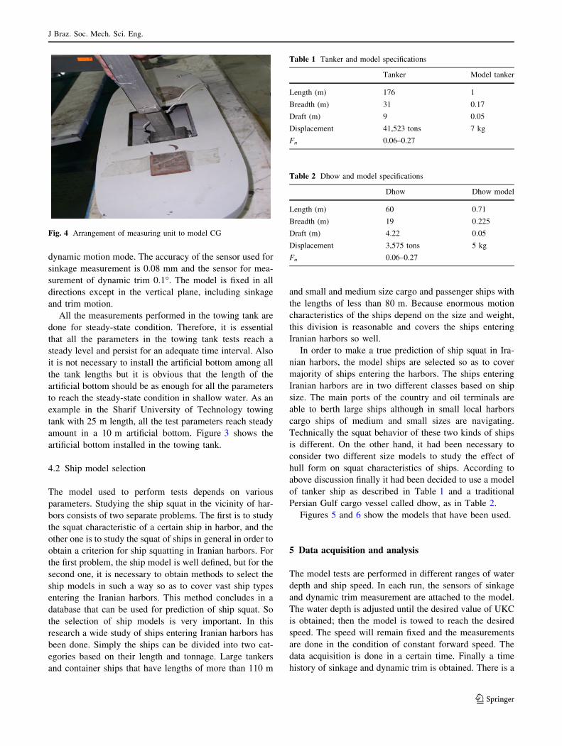
dynamic motion mode. The accuracy of the sensor used for
sinkage measurement is 0.08 mm and the sensor for mea-
surement of dynamic trim 0.1�. The model is fixed in all
directions except in the vertical plane, including sinkage
and trim motion.
All the measurements performed in the towing tank are
done for steady-state condition. Therefore, it is essential
that all the parameters in the towing tank tests reach a
steady level and persist for an adequate time interval. Also
it is not necessary to install the artificial bottom among all
the tank lengths but it is obvious that the length of the
artificial bottom should be as enough for all the parameters
to reach the steady-state condition in shallow water. As an
example in the Sharif University of Technology towing
tank with 25 m length, all the test parameters reach steady
amount in a 10 m artificial bottom. Figure 3 shows the
artificial bottom installed in the towing tank.
4.2 Ship model selection
The model used to perform tests depends on various
parameters. Studying the ship squat in the vicinity of har-
bors consists of two separate problems. The first is to study
the squat characteristic of a certain ship in harbor, and the
other one is to study the squat of ships in general in order to
obtain a criterion for ship squatting in Iranian harbors. For
the first problem, the ship model is well defined, but for the
second one, it is necessary to obtain methods to select the
ship models in such a way so as to cover vast ship types
entering the Iranian harbors. This method concludes in a
database that can be used for prediction of ship squat. So
the selection of ship models is very important. In this
research a wide study of ships entering Iranian harbors has
been done. Simply the ships can be divided into two cat-
egories based on their length and tonnage. Large tankers
and container ships that have lengths of more than 110 m
and small and medium size cargo and passenger ships with
the lengths of less than 80 m. Because enormous motion
characteristics of the ships depend on the size and weight,
this division is reasonable and covers the ships entering
Iranian harbors so well.
In order to make a true prediction of ship squat in Ira-
nian harbors, the model ships are selected so as to cover
majority of ships entering the harbors. The ships entering
Iranian harbors are in two different classes based on ship
size. The main ports of the country and oil terminals are
able to berth large ships although in small local harbors
cargo ships of medium and small sizes are navigating.
Technically the squat behavior of these two kinds of ships
is different. On the other hand, it had been necessary to
consider two different size models to study the effect of
hull form on squat characteristics of ships. According to
above discussion finally it had been decided to use a model
of tanker ship as described in Table 1 and a traditional
Persian Gulf cargo vessel called dhow, as in Table 2.
Figures 5 and 6 show the models that have been used.
5 Data acquisition and analysis
The model tests are performed in different ranges of water
depth and ship speed. In each run, the sensors of sinkage
and dynamic trim measurement are attached to the model.
The water depth is adjusted until the desired value of UKC
is obtained; then the model is towed to reach the desired
speed. The speed will remain fixed and the measurements
are done in the condition of constant forward speed. The
data acquisition is done in a certain time. Finally a time
history of sinkage and dynamic trim is obtained. There is a
Fig. 4 Arrangement of measuring unit to model CG
Table 1 Tanker and model specifications
Tanker Model tanker
Length (m) 176 1
Breadth (m) 31 0.17
Draft (m) 9 0.05
Displacement 41,523 tons 7 kg
Fn 0.06–0.27
Table 2 Dhow and model specifications
Dhow Dhow model
Length (m) 60 0.71
Breadth (m) 19 0.225
Draft (m) 4.22 0.05
Displacement 3,575 tons 5 kg
Fn 0.06–0.27
J Braz. Soc. Mech. Sci. Eng.
123

great difference between the time history of the measured
signals in shallow water and the time history of the mea-
sured signals in deep water. In deep water tests, the mea-
sured signal remains approximately constant during a
considerable portion of the test. However, when the vessel
enters the shallow water it experiences a decaying oscil-
latory motion around a certain limit. This oscillating
motion is very similar to motions of vessels in a seaway.
Therefore, according to seakeeping literature, the motion at
the center of gravity of a vessel is defined as heave motion.
The oscillations damp rapidly and the vessel maintains a
steady vertical displacement at the center of gravity which
is defined as sinkage, and a steady angle of rotation around
the transverse axis which is defined as dynamic trim. This
oscillatory motion has a period equal to a vessel’s natural
period of heave. An example of time history of heave
motion is shown in Fig. 7.
From Fig. 7, it is obvious that the maximum speed of
test in a towing tank depends on the water depth as well. In
order to precisely measure the sinkage and dynamic trim, it
is essential that the model’s oscillatory motions be damped.
The length of the shallow water towing tank is limited.
Therefore, the model’s speed should be below a certain
limit to give the oscillations enough time to decay. The
shallow water model test with forward speeds more than
1 m/s2 are neglected for this purpose.
Since the probability of grounding is so important in
practice, in the model tests the maximum vertical motion of
the ship is defined as ship squat (in bow or aft which is
larger). In each case, the sinkage at the center of gravity of
the model and the dynamic trim are measured, and the
squat is calculated as follows:Fig. 6 Dhow model
Fig. 5 Tanker model
Fig. 7 Example of time history of sinkage in shallow water
J Braz. Soc. Mech. Sci. Eng.
123

squat mð Þ ¼ sinkage in CG mð Þþ longitudinal distance of point to CG mð Þþ dynamic trim ðradiansÞ
ð4Þ
In usual speeds, sinkage is always downward. According
to the ship speed and the hull form, when the dynamic trim
is by aft, the point is defined as AP; and when it is by fore,
the point is located at FP.
It should be mentioned that every test run is executed
twice, and the average value of sinkage and dynamic trim
is used in the calculation of squat. In the cases that the
measured values in two tests are, to a high degree, different
from one another, the test is repeated for the third time and
two closer values are averaged as final amount of the
measured parameter.
One of the main aspects of the model tests in the
towing tank is the possibility of extending the results to
the full scale. The flow around the model should be
similar to the flow around the ship. Similarity of gravity
effects is provided through the Froude number in the
tests. Similarity of viscous effects is not applicable.
Therefore, it is essential to at least maintain the same
regime of boundary layer in the model and in full scale.
In full scale, the boundary layer is almost turbulent. It
seems that the level of turbulence is higher in the model
tests in shallow water so that there will be no need for
turbulence simulators. However in small forward speeds,
the difference of results in model test and full scale may
be more.
The period of time between two successive tests can
affect the results. This interval should be long enough that
vortexes disappear in the towing tank. It is observed in the
tests that more time is needed when performing model tests
in shallow water.
6 Experimental results and validation
There are so many experimental methods for predicting
ship squat in literature. The vast majority of these
methods are based on experimental measurements on ship
models in towing tanks. Several of these model tests were
carried out in the Sharif University of Technology towing
tank and the results are in good agreement with the
published data. In most cases, the results can be expanded
to full scale.
In order to evaluate the squat of ships entering Iranian
harbors, model tests in Marine Engineering Laboratory are
conducted and the results are compared to experimental
formulae based on model tests. To obtain the lower limit of
ship squat, a comparison with Norrbin formula is so suit-
able [1]:
S ¼ 0:01888CB
B
L
T
hV2 ð5Þ
In this formula S is maximum ship squat predicted by
Norrbin formula, CB the block coefficient of the hull form,
B ship breadth in m, L ship length in m, T ship draft in
meters, h water depth in meters, and V is ship speed relative
to flow velocity in kmph.
In order to predict the higher limit for ship squat, the
formula presented by Milward is applicable [1]. This for-
mula can be used up to both the end of the subcritical flow
regime in shallow water and the channel Froude number of
0.4 subcritical region.
S ¼15:0 CBB
L
� �
� 0:55� �
F2nh
1� 0:9Fnh
L ð6Þ
In the following diagrams, the results obtained from
model tests in different speeds and water depths are
compared to Norrbin and Milward formulae. It is clear that
the Norrbin formula is in lower level of value compared to
model tests, which consequently means that Norrbin
formula gives a lower limit for ship squat. Also, the scale
effects of the models are prominent and some of the
differences may be due to the scale effects (Figs. 8, 9, 10).
The results presented in Fig. 11 show that the Norrbin’s
criteria are not accurate in higher forward speeds. In such
occasions the model’s test results should be used directly.
Furthermore, in all diagrams one could see that the model
Fig. 8 Tanker squat, Froude number 0.064
Fig. 9 Tanker squat, Froude number 0.128
J Braz. Soc. Mech. Sci. Eng.
123
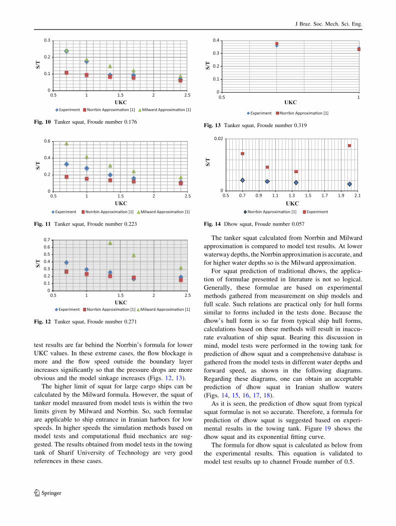
test results are far behind the Norrbin’s formula for lower
UKC values. In these extreme cases, the flow blockage is
more and the flow speed outside the boundary layer
increases significantly so that the pressure drops are more
obvious and the model sinkage increases (Figs. 12, 13).
The higher limit of squat for large cargo ships can be
calculated by the Milward formula. However, the squat of
tanker model measured from model tests is within the two
limits given by Milward and Norrbin. So, such formulae
are applicable to ship entrance in Iranian harbors for low
speeds. In higher speeds the simulation methods based on
model tests and computational fluid mechanics are sug-
gested. The results obtained from model tests in the towing
tank of Sharif University of Technology are very good
references in these cases.
The tanker squat calculated from Norrbin and Milward
approximation is compared to model test results. At lower
waterway depths, the Norrbin approximation is accurate, and
for higher water depths so is the Milward approximation.
For squat prediction of traditional dhows, the applica-
tion of formulae presented in literature is not so logical.
Generally, these formulae are based on experimental
methods gathered from measurement on ship models and
full scale. Such relations are practical only for hull forms
similar to forms included in the tests done. Because the
dhow’s hull form is so far from typical ship hull forms,
calculations based on these methods will result in inaccu-
rate evaluation of ship squat. Bearing this discussion in
mind, model tests were performed in the towing tank for
prediction of dhow squat and a comprehensive database is
gathered from the model tests in different water depths and
forward speed, as shown in the following diagrams.
Regarding these diagrams, one can obtain an acceptable
prediction of dhow squat in Iranian shallow waters
(Figs. 14, 15, 16, 17, 18).
As it is seen, the prediction of dhow squat from typical
squat formulae is not so accurate. Therefore, a formula for
prediction of dhow squat is suggested based on experi-
mental results in the towing tank. Figure 19 shows the
dhow squat and its exponential fitting curve.
The formula for dhow squat is calculated as below from
the experimental results. This equation is validated to
model test results up to channel Froude number of 0.5.
Fig. 10 Tanker squat, Froude number 0.176
Fig. 11 Tanker squat, Froude number 0.223
Fig. 12 Tanker squat, Froude number 0.271
Fig. 13 Tanker squat, Froude number 0.319
Fig. 14 Dhow squat, Froude number 0.057
J Braz. Soc. Mech. Sci. Eng.
123

S
T¼ 0:03018CB
B
Le4:875Fnh ð7Þ
7 Affecting parameters analysis
7.1 Effect of depth Froude number on squat
The measured squat is plotted versus depth Froude number
in Fig. 20 for tanker and dhow model. According to these
results, the ship squat reaches a peak of Fnh = 0.6 for
tanker model and Fnh = 0.48 for dhow model in the sub-
critical region. Therefore, the curvature of the ship’s hull
can reduce the depth Froude number in which the maxi-
mum peak occurs in the subcritical region. In order to
obtain the most satisfactory navigation condition, this fact
should be taken into account in shallow water. Further-
more, in higher depth Froude numbers, for example, Fro-
ude numbers more than 0.6, obvious humps and hollows
are observed in the experiments. For safe navigation in
shallow water, it is recommended to navigate with forward
speeds of hollows in this curve.
7.2 Effect of trim and sinkage on ship squat
As shown in Fig. 20, humps and hollows are seen in the
squat of the vessels at different depth Froude numbers.
Fig. 15 Dhow squat, Froude number 0.114
Fig. 16 Dhow squat, Froude number 0.171
Fig. 17 Dhow squat, Froude number 0.227
Fig. 18 Dhow squat, Froude number 0.269
Fig. 19 Dhow squat versus channel Froude number
Fig. 20 Squat versus depth Froude number
J Braz. Soc. Mech. Sci. Eng.
123

These humps and hollows due to interaction of ship sink-
age and trim change in shallow water. As an example, the
squat of tanker model, heave motion, and dynamic trim are
plotted together in Fig. 21.
In some Froude numbers, the heave motion and dynamic
trim angle interaction is positive which results in more ship
squat. For example, in Fnh = 0.48 a minimum is observed
in the heave motion but the maximum in trim angle curve
removes the effect and no certain peak is seen in the squat
curve. Another cancellation effect occurs in Fh = 0.86,
0.95, 1.00. As it is seen in the Froude numbers more than
0.8, the interaction between dynamic trim and heave
motion is always cancellation, but at lower depth Froude
numbers, these interactions are magnified.
8 Regression model
In order to evaluate the amount of tanker and dhow squat
for different water depths and speeds, a regression analysis
has been conducted and a regression formula is obtained
from the model tests results. The formulae give the amount
of squat as a function of UKC and motion Froude number
for model. Figures 22 and 23 show the normal probability
plot of the Squat/T, considering parameters involved in
regression analysis. The interaction of these two factors is
taken into account.
S
T¼ �0:133288þ 0:0404538 UKCþ 2:18262 Fn
� 0:656682 UKC� Fn; for tanker ð8ÞS
T¼ �0:0612834þ 0:0271849 UKCþ 0:839984 Fn
� 0:278239 UKC� Fn; for dhow ð9Þ
The R2 factors for Eqs. (8) and (9) are 91.81 and 86.4 %,
respectively, which prove the extracted equations are
satisfactory in practice for this range of results.
Most tanker ships and dhows navigating in the vicinity
of Iranian harbors have hull forms similar to the models
used in these experiments, so that the above equations can
be used to estimate these types of vessel squats in shallow
fairways. It goes without saying that these formulae are
based on a limited number of model tests, which means one
should exercise caution using them. First of all, the
geometry of the hull should fit well within the specifica-
tions of the hulls tested in this paper. Second, the UKC and
speed of the vessel must be within the range as well. If the
regression formulae are used in other cases, there may be a
serious error in the calculations. However, obtaining more
Fig. 21 Squat, heave, and
dynamic trim versus depth
Froude number for tanker model
Fig. 22 Normal probability plot of measured squat/T for tanker
Fig. 23 Normal probability plot of measured squat/T for dhow
J Braz. Soc. Mech. Sci. Eng.
123

precise regression formulae demands more towing tank
tests. By introducing the forward speed Froude number and
UKC in the Eqs. (8) and (9), the vessel squat can be
approximated in practice.
9 Conclusion
In this study, squat phenomena have been investigated
experimentally. The results obtained can be used as an
appropriate database for tanker ship and dhow squat pre-
diction in shallow waters. According to the test results,
squat magnitude is very high for the models studied.
In the model tests, it is shown that in the limiting con-
ditions, the squat of this vessel can reach thirty percent of
ship draft, which is seriously dangerous for tanker navi-
gation in shallow water due to grounding risks. Further-
more, in this study, a well-defined method for predicting
ship squat is introduced and facilities are provided in the
towing tank. In addition, it is shown that ship squat vari-
ation with depth Froude number has distinct humps and
hollows according to Fig. 20. Therefore, in a limited range
of speeds and depths the fluctuations in ship forward speed
can reduce the amount of squat significantly. Different
formulae have been published in navigation guidelines
across the world. Most of these relations are very simple
and hull form is not considered as a result of which the
actual ship’s hull form becomes far from the hull forms
tested which subsequently leads to less accurate squat
prediction through such relations. In the current paper, the
results of model tests of dhow are compared to the pub-
lished data which means that empirical or theoretical for-
mulae presented in the literature are not applicable in these
cases. The CFD approach may be an alternative to the
model tests in these cases. In cargo ship operations a few
centimeters of draft increment may result in considerable
payload and benefit. In these cases, accurate squat simu-
lations such as the procedure described in this paper will be
highly beneficial.
References
1. Milward M (1996) Review of prediction of ship squat in shallow
waters. J Navig 49:77–88
2. Barras CB (2004) Squat formula for ships in rivers. The Naval
Architect, Royal Institution of Naval Architects, London
3. Havelock TH (1939) Note on the sinkage of a ship at low speeds.
Z Angew Math Mech 19:202–205
4. Constantine T (1961) On the movements of ships in restricted
waterways. J Fluid Mech 9:247–256
5. (1970) Steel, C.O.C. A.A.A. Surface, Naval facilities engineer-
ing command
6. Tuck EO (1966) Shallow water flows past slender bodies. J Fluid
Mech 26:81
7. Tuck EO (1967) Sinkage and trim in shallow water of finite
depth. Schifistechnik 14:92–94
8. Ang WT (1993) Nonlinear sinkage and trim for a slender ship in
shallow water of finite width, Internal report, University of
Adelaide
9. Gourlay T (2006) Flow beneath a ship at small underkeel clear-
ance. J Ship Res 50:250–2258
10. Gourlay T (2000) Mathematical and computational techniques for
predicting the squat of ships. Ph. D thesis, University of Adelaide
11. Jachowski J (2008) Assessment of ship squat in shallow water
using CFD. Arch Civil Mech Eng 8:1
12. Dand IW, Ferguson AM (1973) The squat of full ships in shallow
water. Trans RINA 115:237–255
13. Ankudinov V, Dagget JC (1996) Squat prediction for ship
maneuvering applications. In: Proceedings International Confer-
ence on Marine Simulation and Ship Maneuverability. Denmark,
Copenhagen, pp 9–13
14. Dufflied RJ (1997) Investigation into steady and unsteady state
squat. Naval Architecture Bachelor Thesis, Australian Maritime
College
15. Cohen S, Beck R (1983) Experimental and theoretical hydrody-
namic forces on a mathematical model in confined waters. J Ship
Res 27(2):75–89
16. Gucma L (2005) Risk modeling of ship collision factors with
fixed port and offshore structures. Maritime University of
Szczecin
17. Beaulieu C, Gharbi S, Ouarda T, Seidou O (2009) Statistical
approach to model the deep draft ships’ squat in the St. Lawrence
waterway. J Waterway Port Coastal Ocean Eng 135(3):80–90
18. Gucma L, Schoeneich M (2008) Monte Carlo method of ship’s
under keel clearance evaluation for safety of ferry approaching to
Ystad Port Determination. J KONBiN 8(1):35–44
19. Department of Trade (1980) Interaction between ships, Merchant
Shipping Notice No. M930
20. Ortlepp B (1989) Natural Squat, Canadian maritimes sailing aids,
vol 4. Peltro Ltd, Canada
21. Admiralty manual of navigation (1987) HMSO, vol 1, p 308
J Braz. Soc. Mech. Sci. Eng.
123

![humpbackwhales Research - Portal · 3 rsos.royalsocietypublishing.org R.Soc.opensci. 3:160616..... also found in deep waters [26,27] and in shallow waters extended offshore during](https://static.fdocuments.us/doc/165x107/5ea1d4344125f0619e1831bd/humpbackwhales-research-portal-3-rsosroyalsocietypublishingorg-rsocopensci.jpg)


