Experimental Establishment of the Relativity of Time - Orgone · Experimental Establishment of the...
19
1, 19JZ PIIYSICAL REVIEW VOLUME 42 Experimental Establishment of the Relativity of Time B, Roy J. KENNEDY AND EDWARD M. TIIORNDIKE University oJ Washington and Institute of Brooklyn (Received July 9, 1932) None of the fundamental experiments on which the restricted principle of rela- tivity is based requires{or their explanation that the classical concept of absolute tillle be Inodified; the present experiment was devised to test directly whether time satisfies tile requirenlents of relativity. It depends on the fact that if a pencil of hOlnogeneolls light is split into two components which are made to interfere after traversing paths of different length, their relative phases will depend on the translational velocity of the optical system unless the Lorentz-Einstein transformation equations are valid. I-Ience, such a system at a point on the earth should give rise to an interference pat- tern which varies periodically as the velocity of the point changes in consequence of the rotation and revolution of the earth. The effect to be expected for a small velocity is so very small that it has been necessary to devise a special source of light, an inter.. ferometer of great stability and a refinement of the technic of measuring displace- nlcnts ill the interference pattern. With the apparatus finally employed, we have shown that there is no effect corresponding to absolute tinle unless the velocity of the solar system in space is no more than about half that of the earth in its orbit. Using this null result and that of the Michelson-Morley experiment we derive the Lorentz- transformations, which are tantamount to the relativity principle. A MONG the several classical experimel1ts which suggested the restricted 1""1. principle of relativity there appears to be none in which any question as to the nature of time is involved. That is, in any of them, time as indicated IJy all ideal clock moving with the earth might be related in any way to that indicated by a hypothetical fixed clock without at all affecting their results, at least illsofar as can be inferred from such theories of the experiments as we are present able to construct. 111 experiments such as those of Rayleigh and Brace, of 'frouton and Noble, and of Fizeau, all of which yielded null results, thel·e is present the theoretical difficulty that unknown properties of matter are involved. The Michelsol1-Gale experiment gives a positive result, which is consistent with the concepts of either relative time or absolute time. In fact, it seems that the only experiment heretofore reported that permits of any definite interpretation is that of Michelson and Morley; and the null result of this experiment is completely explained if we suppose that space dimel1sions in the direction of motion are contracted by an amount depending upon a suitable function of velocity; so here, too, no question as to time is raised. lienee, although such experiments have suggested the relativity theory. they do not form a sufficient basis for the logical derivation of it. It appears, then, that the theory has needed confirmation, particularly in its most revolutionary aspectj i.e., its denial of a significance for absolute time. Such confirmation has been obtained in the work reported in this paper, and by combining our results with those of the Michelson-Morley experiment, we derive the Lorentz-Einstein transformations which are well known to em- brace the whole theory. 400
-
Upload
trinhkhanh -
Category
Documents
-
view
223 -
download
0
Transcript of Experimental Establishment of the Relativity of Time - Orgone · Experimental Establishment of the...

NOVI~MBER 1, 19JZ PIIYSICAL REVIEW VOLUME 42
Experimental Establishment of the Relativity of TimeB, Roy J. KENNEDY AND EDWARD M. TIIORNDIKE
University oJ Washington and PoZ'Ytecl~nic Institute of Brooklyn
(Received July 9, 1932)
None of the fundamental experiments on which the restricted principle of relativity is based requires {or their explanation that the classical concept of absolute tilllebe Inodified; the present experiment was devised to test directly whether time satisfiestile requirenlents of relativity. It depends on the fact that if a pencil of hOlnogeneollslight is split into two components which are made to interfere after traversing pathsof different length, their relative phases will depend on the translational velocity ofthe optical system unless the Lorentz-Einstein transformation equations are valid.I-Ience, such a system at a point on the earth should give rise to an interference pattern which varies periodically as the velocity of the point changes in consequence ofthe rotation and revolution of the earth. The effect to be expected for a small velocityis so very small that it has been necessary to devise a special source of light, an inter..ferometer of great stability and a refinement of the technic of measuring displacenlcnts ill the interference pattern. With the apparatus finally employed, we haveshown that there is no effect corresponding to absolute tinle unless the velocity of thesolar system in space is no more than about half that of the earth in its orbit. Usingthis null result and that of the Michelson-Morley experiment we derive the Lorentz]~instein transformations, which are tantamount to the relativity principle.
A MONG the several classical experimel1ts which suggested the restricted1""1. principle of relativity there appears to be none in which any questionas to the nature of time is involved. That is, in any of them, time as indicatedIJy all ideal clock moving with the earth might be related in any way to thatindicated by a hypothetical fixed clock without at all affecting their results,at least illsofar as can be inferred from such theories of the experiments as weare ~tt present able to construct. 111 experiments such as those of Rayleigh andBrace, of 'frouton and Noble, and of Fizeau, all of which yielded null results,thel·e is present the theoretical difficulty that unknown properties of matterare involved. The Michelsol1-Gale experiment gives a positive result, whichis consistent with the concepts of either relative time or absolute time. Infact, it seems that the only experiment heretofore reported that permits ofany definite interpretation is that of Michelson and Morley; and the nullresult of this experiment is completely explained if we suppose that spacedimel1sions in the direction of motion are contracted by an amount dependingupon a suitable function of velocity; so here, too, no question as to time israised. lienee, although such experiments have suggested the relativity theory.they do not form a sufficient basis for the logical derivation of it.
It appears, then, that the theory has needed confirmation, particularlyin its most revolutionary aspectj i.e., its denial of a significance for absolutetime. Such confirmation has been obtained in the work reported in this paper,and by combining our results with those of the Michelson-Morley experiment,we derive the Lorentz-Einstein transformations which are well known to embrace the whole theory.
400

RELATIVITY OF TIME 401
The principle on which this experiment is based is the simple propositiollthat if a beam of homogeneous light is split at a half-reflecting surface intotwo beams which after traversing paths of different lengths are broughttogether again, then the relative phases of the superposed beams will depelldupon the velocity of the apparatus unless the frequency of the light dependsupon the velocity in the way required by relativity. Furthermore, tIle pllasedifference can be made to determine the positions of fringes in an interferencepattern, so that by measuring these positions for various velocities of thesystem, the question whether the frequency follows the relativity requirement can be decided. The variation of the velocity of the system comes aboutbecause of the motions of rotation and revolution of the earth.
The theory of this experiment requires the following two assumptions:(a) There exists at least one coordinate system in which Huyghen's principleis valid and the velocity of light is the same in all directions. This assumptionis unobjectionable from the standpoint either of relativity or of any plausiblehypothesis involving an ether; for relativity, it is true for all uniformlymoving systems, and in the latter case for any system at rest in the ether.(b) The Michelson-Morley experiment indicates that a system moving withuniform velocity 'lJ with respect to such a system has dimensions in the direction of motion contracted in the ratio [1-'I)2/C2]1/2 as compared to dimensionsin the fixed system, while dimensions perpendicular to this direction are un..cllanged. This is in part assumption, for although there can be little doubtthat the experiment yields a strictly null result, nevertheless it actuallyshows only that dimensions in the direction of and perpendicular to tile motion are in the ratio mentioned; either of these dimensions migl1t be anyfunction of the velocity so long as that ratio is preserved.
_-..)J A..... _B__
Fig. 1.
Let us consider one such system 8', and suppose that a systeln S (attached,for instance, to the surface of the earth) moves practically uniformly Wit!lvelocity fJ with respect to it. In S is set up an arrangement for producinginterference; i.e., one in which a pencil of homogeneous light is divided asmentioned above into two pencils which are recombined after traversingpaths of different lengths. We can simplify the discussion by treating thegeneral case instead of the particular arrangement used in the experiment,and by adopting a rule regarding expressions for the distances, angles andtimes in system S that will be of interest; i.e., the magnitudes of these quantities will be expressed by unprimed letters when they are referred to standards moving with S, and by the same letters primed when referred to standards fixed in S'.
The path of a typical ray with respect to S can be represented schematically as in Fig. 1 where the ray coming from the left is divided at A into rays1 and 2 which recombine at B. The courses of the same rays with respect to

402 R. J. KENNEDY AND E. M. THORNDIKE
S' are evidently determined by the requirement that to each element ds' ofa ray is to be added an elementary vector 'Odt' where dt' is time required{Ole light to traverse the element, and c is the velocity of light with respect toS't The length of the resulting element is evidently cdt'; hence c2(dt')2 =(dS')2+v2(dt')2+ 2tJ as'dt' cos 6'. Hence,
as'dt' == [Ii cos 8' + (1 - (j2 sins 8') 1/2] (1)
e(l - PI)
where (3 =v/c and 8' the angle between fJ and the element as'.If for the moment we consider a set of rectangular coordinates· in Sand
S' with corresponding axes parallel and x-axes parallel to velocity !I, we havefrom assumption (b)
as' = [(dx')S + (dy')1 + (dZ/)2]1/2 == [(dx)2(1 - P~) + (dy)a + (dZ)I]l/l
= ds [1 - tJ{~:)2 Jill = ds(1 - tJ2 cos2 8)1/2
dx' dx(1 - ~2) t/2 (1 - {j2 )1/2COS 0' = - = = cos ()
ds' ds(l - (j2 cost 8)1/2 1 - p2 coss 8
sin9 0' = sin! 9/(1 - pt cost 0).
When these expressions are substituted in Eq. (1), it reduces to
de' = [as/c(l - ,82)1/2](1 +P cos 8), (2)
the rigllt side of which equation involves only quantities referred to standardsmoving with S. The time for light to traverse the whole ray AB along path 1is therefore
t1' = i dt' = l/e(1 - tJ2)1 /21: (1 + tJ cos 8)ds
and a similar expression holds for path 2. Hence difference of time for thetwo paths is
tl' - tl = 1/e(1 - tJ l )1/J{ i ds - 1:ds + tJ[i cos 6 ds - 1:cos (J ds]}.
The term ill brackets multiplied by (3 vanishes, since in order to interfere therays must intersect, and therefore their projections on the line joining A andB are equal; these projections are the integrals in brackets. Hence
tl' - ts' == (Sl - $2)/c(1 - PS)112 = As/c(l - ~t)1/2, say,
and the number of waves corresponding to this difference of time is
n = V'(tl' - t2') == v'as/c(l - P2)I/J (4)
where p' is the frequency of the light employed as measured by an observerin S'. This l1umber n is seen to be independent of orientations. lengths and

RELATIVITY OF TIME 403
dispositions of paths, but to depend upon difference of path.lengtl1s, therelative velocity of Sand S' (through~)and the frequency.
The foregoing treatment is strictly valid only if the moving system is regarded as not subjected to forces, but is undoubtedly sufficient for tIle purpose in the small constant field of gravitation and acceleration at tile surfaceof the earth. Moreover, althougll the rotation of tIle apparatus with the earthinvolves a slight effect on the time difference computed above (whether re..garded from the standpoint of relativity or classical theory), it turns out tobe altogether negligible in amount. This effect is a function of l·otatiol1alvelocity, not of orientation of apparatus.
We have now to consider the effect of a change in the velocity f} on thenumber n expressed by Eq. (4). In that equation c is evidently a constant,while the difference ~s, because it is referred to standards moving with thesystem, is constant unless the courses of the rays between tIle points of separation and recombination are dependent on the velocity; that this is not tIlecase can be shown by Huyghens' principle. A direct cOl1sequence of thisprinciple is that the course of the ray is determined by the condition that thetime required for traversing the path is a minimum compared with the timefor any neighboring path. Now, Eq. (3) expresses the time in terms of coordinates moving with S, and if minimized in the usual way would yield theequations of the paths. For the present purpose, however, it is unnecessaryto carry out this operation. Rewriting (3) we have
I' = l/c(1 - Pll)1/2{ LB as + pLBcos (J as}.It will be observed that although the expression involves the velocity of themoving system, nevertheless the course of the ray is quite independent of it.Tl1at this is so is evident from the following considerations: the secondintegral is equal to the projection of the path on the line joining A and B,and being the same therefore for all paths, cannot contribute to thedetermination of the minimizing path. The first integral is expressed in terms ofdistances referred to standards moving with the system and so is independen tof the velocity. Hence the actual courses of the rays, which are got by minimizing integrals of this form, are independent of the velocity, and !J.,~ is a constant. This proof is essentially tllat of Lorentz extended by the inclusion ofthe contraction hypothesis.
The quantity 11' in Eq. (4) is the only one whose possible variability withvelocity remains to be considered. From the standpoint of relativity, 11'
=JI(1-~2)1/2 where II is the constant value of the frequency which would bedetermined with standards moving with S; this value of v' would evidel1tlymake n a constant. Furthermore, it will be shown later that insofar as theatom is to be regarded as a typical clock, the Lorentz-Einstein transforlnations can be derived from this relationship and assumption (b). If, on the otherhand, 'II' ~p(1-{32)1/! these transformations do not apply and it turns outthat there exists but one system S' satisfying assumption (a); this uniquesystem would be the absolute reference frame postulated in tlle classical

404 R. J. KENNEDY AND B. M. THORNDIKE
ether theory. In this case n is evidently a function of the velocity of S withrespect to the absolute reference frame. Evidently, then, the relativityhypothesis can be tested by determining whether n is constant as fJ changesin consequence of the motions of rotation and revolution of the earth.
For the present purpose the total velocity of the apparatus can be got byadding vectorially a presumably constant velocity Vo of the sun, the orbitalvelocity VI of the earth and the circumferential velocity 7J:a due to the rotationof the earth (taking account of latitude). Its square can be reduced to
v2 = vo" + "It + VI' + 2V.xVl sin (81 - 6'1) + 2fJ~V2 sin (62 - 6)1) + 2"1t'S COS (61- OJ),
where f,la is the projection of flo on the orbital plane, fJD is projection of flo onthe equatorial plane, Cl'1 and (1)1 are constants related to the direction of va,and 81 and 8J are angles expressing the position of the earth in its orbit andits orientation on its axis with respect to the fixed-stars.! This procedure assumes only that the fixed-star system has no great angular velocity withrespect to the fundamental system S'; there is an unimportant approximation in the last term.
In order to get an idea of the magnitude of the effect that might be expected, let us assume that .,,, =p and replace 11 by c!"; then (4) becomesn =!l.s/"'A(1-~2)1/Z. Expanding this, ignoring terms in {j above second degree,substituting for the velocity from the expression above. and gathering constant terms into one,
n == (4s/X)(1 + !(VS/cl) + · · · )= (As/A,'},) ["a~l sin (61 - 6)1) + 'lJfjVS sin «(JI - 6J2) J+ a constant
=~+~. 00Here the variable part of n is represented by Bn and the constant by no andwe assume fI" and lip to be large compared with the orbital and circumferential velocities '01 al1d Vt. Hence an should be proportional to the sum of aterm with a period of a year and one with a period of a sidereal day.
In performing the experiment, we wish, of course, to make an as large aspossible. The only factor that can be controlled is the ratio /is!", tIle largestfeasible magnitude of which is a measure of the homogeneity of the light.For various reasons the most suitable light seems to be the mercury line ofwave-length 5461. With this, sufficiently clear interference fringes could begot when ~s was as large as 318 mm (the value finally used) and on substituting this in the expression for n it turns out that the rotation of the earthwould produce a daily variation of a thousandths of a fringe for 200 km per
1 More specifically, 81 is the angle between the projection of flo on the orbital plane and adirection in that plane determined by the angle (dl which depends on the position of the earthin its orbit or the time of year at which 91 is taken as zero. Similarly, 81 is the angle between theprojection of flo on the equatorial plane and a direction in that plane determined by the angle~ which depends on the time of day at which 81 is taken as zero. In the reduction of the data,the B's are taken as zero at the beginning of each run. so the ~·s depend on the times of startingruns. In the comparison and final summary of data, the 9'8 are of course referred to the samesidereal time.

RELATIVITY OF TIME 405
second, while the orbital motion would produce the same variatioll in sixmonths for 3 km per second.
Because of the probable minuteness of these effects it was necessary tocontrive new ways of detecting them. In the rather complicated Jnethodfirst proposed2 the phase variation would show itself in the rotation of theplane of polarization of a beam resultillg from the SUIJerposition of twooppositely circularly polarized beams. This scheme, altIl0ugh theoreticallycapable of great precision, was abandoned in favor of tIle much silnrJ1er onefinally employed. In the latter, ordillary interference rings were forlned andphotographed, and the problem became one of measuring very small changesin the diameters of the rings. It was satisfactorily solved by devising a sl)ecialcomparator which will be discussed later.
Evidently, it was necessary to tal{e every precaution to keep the eXI)erimental conditions constant; we were able, in fact, to reduce tIle average dG.ilyperiodic error in asp.. to about two parts in 1010• 1"his great stability was attained mainly by using interference apparatus made almost entirely of fusedquartz and kept in a vacuum at a temperature constant to within alJout athousandth of a degree. The apparatus was furthermore (!lartlyaccidentally)cODlpensated for temperature to such an extent that one degree change produced a shift of only about a hundredtIl of a fringe. TIle vacuum was employed as simplest way to eliminate variations in pressure, which would havecaused variations in index of refraction of optical patl1s, and, by Jllechanicalaction, variations in lengtlls of paths.
Several disturbing factors producing spurious effects had to be dealt with.Perhaps the most troublesome was tIle variability ill density of the photograplls due (in the earlier green-sensitive plates) to rapid agil1g whicl1 affectedthe emulsions in varying degrees. Since tIle photographic effect of light isnot proportional to its intensity, it follows tllat a spurious displacelnel1t of allinterference pattern of the type used is to be expected if the dellsity of thephotographs is not constant. The methods adopted to elimilla.te this andotller difficulties are discussed elsewhere in the paper.
ApPARATUS AND EXPERIMENTAL PU.OCEDUl~E
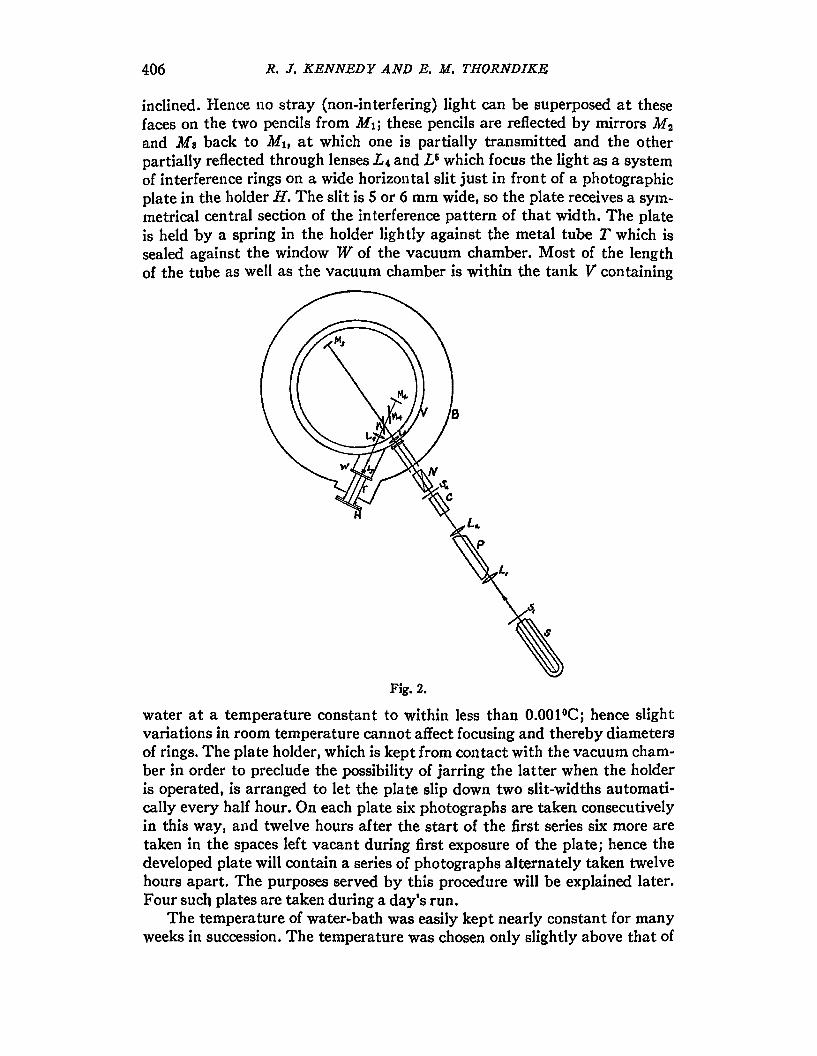
The general arrangemel1t of the experimelltal apparatus is sl{etched itlFig. 2. Light from source S passes through a small circular openillg in screellSI, is rendered approximately plane-parallel by lens L1 is dispersed ill directvision prism P and the green (~5461) image of first opening is focused over asecond one in screen S2 by lells L". The water-cell C is to al)Sol·ll stray heatradiation. The green light from second opening is polarized l>y nicol })riSln
N so that the electric vector is horizontal, and then enters the vaCUUl11 chamber V through a window and is concentrated by lens La to the extent requiredto produce the greatest intensity in interference pattern. 1"he light is the!lsplit into two pel1cils at the half-reflecting mirror M 1 whicll is inclined at SUCll
an al1gle (Brewster's angle) tllat reflection of the polarized ligllt occurs onlyat its platinized face; the faces of the compensating plate M 4 are equally
t Kennedy, Phys. Rev. 20, 26 (1922).
406 Ii. J. KENNEDY AND E. M. TliORNDIKE
il1clined. I-Iel1ce 110 stray (Ilon-interferillg) light can be superposed at thesefaces on the two pencils from 11ft ; these pencils are reflected by mirrors M2
and Ma back to 1l11, at which one is partially transmitted and the otherpartially reflected through leJ1SeS L", and L6 which focus the light as a systemof interferel1ce ril1gs on a wide horizol1tal slit just in front of a photographicplate ill the llolder If. The slit is 5 or 6 mm wide, so the plate recei\res a sYlnInetrical central section of the interference pattern of that width. The plateis held by a spril1g in the holder lightly against the metal tube 7' which issealed against the window W of the vacuum chamber. Most of the lengthof the tube as well as the vacuum chamber is within the tal1k V containillg
Fig. 2.
water at a temperature constant to within less than O.OOl°C; hence slightvariations ill room temperature cannot affect focusing and thereby diametersof rings. The plate holder, which is kept from COl1tact with the vacuum chamber in order to preclude the possibility of jarring the latter when the holderis operated, is arranged to let the plate slip down two slit-widths automatically every half hour. On each plate six photographs are taken consecutivelyin this way, aIld twelve hours after the start of the first series six more aretaken in the spaces left vacant during first exposure of the plate; hence tIledeveloped plate will contain a series of photographs alternately taken twel,Tehours apart. The purposes served by this procedure will be explained later.Four such plates are taken during a day's run.
The temperature of water-bath was easily kept nearly constant for mal1Yweeks in succession. The temperature was chosen only slightly above that of

RELATIVITY OF TIME 407
room, the water was circulated continuously and the mercury-toluene tIler..mostat was arranged to control the potel1tial of the grid of a vacuum tulJewhicll actuated tIle relay in the heating circuit-ill this way ollly a minutecurrellt is broken at the mercury surface and it does not become contaminatedwith a film of oxide. The optical part of the apparatus was enclosed ill asmall dark room within a larger one. The temperature of the inner rOOlD waskept constant to within a few hundredths of a degree, that of outer room towithin about a tentll.
The interference apparatus consisted essentially of a set of four illterferometer plates of the beE;t quality obtainable, mounted on a circular fusedquartz base 28.5 cm in diameter by 3.8 em thick. The method of mounting theplates is perhaps worth describing: the support of each plate was cut from aflat plate of fused quartz, and fused to a tapered plug of the same materialwhicll, after being ground to fit a tapered hole in the base, was etched away
o
Fig. 3.
over the whole conical surface except ill four spots of two or tllree squaremillinleters area, which were therefore the sole points of COl1tact of tIle I)lugwith the base. This procedure was necessary to insure a defil1ite fixed positiol1of plug, since if it were merely ground il1tO the plate it would probably fitthe llole only in a region near its middle. The positiol1S of the bearing 81)ot8are indicated by tIle small squares in Fig. 3, the dotted Olle being 011 theopposite side of plug from the others. TIle plugs were held down by lightspril1gs as shown in the figure. TIle end mirrors were circular etalol1 plcltes25 mm in diameter. Tlleir supporting frames were fasllioned so as to IJrovidethree projections of quartz against which the mirror was held by a light S}Jritlgopposite each projection. "fhe faces of the projections were ground flat andso as to be very nearly ill a vertical plane wIlen the frame is in place 011 thebase. Final adjustment of mirrors was made by rotatil1g them about t]leirhorizontal axes; it will be evident that ill tllis way (because of sligl1t in-

408 R. J. KENNEDY AND E. M. THORNDIKE
clination to each other of the faces of the mirror) a very fine adjustment canbe made. I t was sufficient simply to rotate the mirrors with the unaidedfingers, to correct for the departure from the vertical, while viewing the interference rings with a telescope. The reflecting surfaces were of platinumapplied by cathode deposition. It was impossible to use silver for the purposebecause traces of mercury vapor in the vacuum chamber would quickly dissolve it. The light lens system which formed the rings on the photographicplate was attached to the base by means of invar plugs similar to those described above.
The quartz base rested on a piece of uniform velour, the back side ofwhich was cemented to a heavy fiat brass plate which was supported in anaccurately horizontal position at three points. Each fiber of the nap of thevelour thus served as a tiny spring so that the weight of the quartz plate wasevenly distributed; this is important t since a fused material of this sort is·essentially only semi-solid. The friction between the velour and the roughbottom face of the base sufficed to hold the latter accurately in position.
In order to produce interference under the existing condition of largedifference of paths of the two beams, the image in the half-reflecting mirrorof the face of either end-mirror must be nearly parallel to the face of theother end-mirror; it will be shown that such an adjustment of the mirrorsgives rise to a pattern consisting of a series of concentric circular rings. Inorder that the effective diameter of each ring may be sensibly independentof accidental variations in distribution of light intensity over the faces ofmirrors and with respect to direction in the beam, it is necessary to make thisparallelism very accurate. The accuracy of adjustment could be tested bythe simple procedure of moving a broad slit in various directions across thepencil incident on the half-reflector while the rings were observed in a tete..scope or photographed; when the diameters of rings were constant for allpositions of slit the adjustment was the best obtainable.
The particular spectral1ine employed in the experiment was chosen onbasis of several requirements. As has been pointed out, it must be capableof producing interference with large path-difference; it must also be entirelycontrollable as to intensity, the intensity must be fairly large, and the linemust be easily separable from adjacent ones. On the whole, these conditionsseemed best satisfied by the line A5461 of mercury. The homogeneity of anylight is roughly proportional to the inverse square root of absolute temperature of source; hence the first source employed was a water-cooled mercuryarc. This produced excellent interference rings, but it was soon noticed thattheir diameters depended on the part of the arc from which the light wasta)cen; this suggests a Doppler effect due to motions of evaporating molecules from the hot liquid surface where the arc was brightest. Such an effectdue to velocities variable by only a few centimeters per second would evidently be objectionable in view of the stability required.
The source finally used was an electrodeless discharge in unsaturatedmercury vapor. The tube is sketched in Fig. 4. The inner tube in which thedischarge took place was connected to a continuously operating pumping

RELATIVITY OF TIME 409
system through a capillary tube (heated to prevent condensation in it) of suchlength and diameter as to keep the pressure of the vapor just below tllat ofsaturated vapor at the existing temperature. The vapor was SUPIllied by themercury well at the rear of tube, and the small amount escapil1g throngllthe capillary would condense and return by way of the other vertical tube.The temperature of the source, and thereby the pressure of vapor, were keptconstant by means of carbon-tetrachloride in the jacket surrounding theinner tube; the liquid was maintained at its boiling-point by Ileat from thedischarge, and its vapor was condensed and returned by the water-cooledcondenser connected to top of jacket. It will be evident that with tIle discharge occurring at some distance from the mercury well, first-order Dopplereffects would be eliminated since no mercury condenses in the forwal-d part
e0l1den8er
meyc",,..ywell
Fig. 4.
of the tube and therefore velocities of vapor molecules are on average samein all directions. Electrical energy was supplied by a coil of some thirty turnsof wire around the outside of the jacket, in which oscillations of 20 meterswave-length were produced by a 75-watt transmitting tube. 1"llis dischargeproduced a uniform steady glow over nearly the whole diameter of the innertube, and the interference rings were completely free from the fluctuationsin brightness and diameter WIlich were visible with the ordinary arc. Duringa run, and for some time in advance of it, the tube was kept in continuousoperation in order that all conditions should be steady. It was fOUl1d thatthe frequency of the light depended on the temperature of tIle cooling liquidand the voltage applied to oscillator, so these factors had to be closely controlled. These effects probably arise from the complicated structure of thegreen line; its "frequency," as inferred from the interference pattern, is ofcourse a sort of mean of the frequencies of its components, weighted according to their intensities. It is to be mentioned that each of several attempts to

410 R. J. KENNEDY AND E. M. THORNDIKE
use sealed..off tubes failed; after a few minutes of operation with such tubesthe rings would disappear, presumably because the oscillatory dischargereadily excited a green band in traces of oxygen which probably remain intube.
In view of the theorem of Lorentz previously discussed, the usual theoryof interference for stationary systems can be applied directly to the presentsituation. In Fig. 5, A represents the surface of one end-mirror and B the
R
AFig. S.
BFig. 6.
image of the other at distance l from A. Since A and B are parallel, tIle rayR impinging on both at angle 8 produces on reflection the two parallel raysR1 and Rs• If these are brought to a focus, the difference between the lengthsof their paths will evidently be ab+be. Now
a'6 = l/cos 0, be = ab cos 2fJ. ab + be == (Z/cos 8) (1 + cos 28) == 2l cos 8.
For constructive interference, this path..difference must contain an il1tegralnumber of waves; hence the cones of rays for which 2l cos O,(i = 1, 2, 3, · · · )equals a series of consecutive integers· can be brougllt to a focus as a seriesof concentric rings of radii r, == (sin (Ji)/k1, where kl is a constant dependingon magnification of lens system producing the interference pattern. Nowab+be is the quantity As in Eq. (4); hence ~s,==21cos8i=2l(1-k12r,2)1/2and
n=2J)ll(l-klt,,2)1/2/c(1-~2)1/2. It is convenient to consider only the centralray, and to express its phase in terms of the radii of the rings. For this rayr=O, so
n == 2,,'I/c(1 - P2)lJ3 = no + p (6)
where no is an integer and p a fraction. In general, for constructive interfer..ence n=no-i. Then
no - i = [2,'I/c(1 - ~2)1/2](1 - k]2y,l)1/1 == (no + p)(l - k1I'i2)1/1.
:. p = (no - i)/(l - k1'Jrj2)1/2 - no = no - i + i(no - i)kf,,1 - no · · ·
= (k/2)r,'l - i, (7)
approximately; here k is a new constant. The approximations are justifiedsince n is of order 106Xi and k1rt has a maximum value of about 10-2 for therings measured. From Eq. (7) we find on differentiating
8 When the distances are expressed in wave-lengths.

RELA.TIVITY OF TIME 411
(9)
(10)
8p == kr,Br, == kr,.8'1 == • • • • (8)
If measurements 6r, of the values of the variations in r, are made for eacl1of a number of rings of orders m to p, the mean value of 8p computed fromthem is
k p
8p = Ert 8,,-p-m+l fA
It will be convenient to have tJp in another form. In the filIal summary of datathere are many values of Bp to be averaged for each value of the hypotheticalvelocity. It is clear, then, that the final average will be unaffected if we re~
place the variations ari in (8) by their individual measured values 8rit so thatr,6ri= rl*i- Multiplying and dividing the right side of Eq. (9) by L~ l/ri itbecomes
k L-ap =-- 6r·L<1/ri) ,
when the expressions (r'/'/)6r, that appear in the product are replaced by8r/- Since we are dealing with extremely small variations in the radii, theradii can be measured and ~l/ri computed once for all for a given adjustmentof apparatus; then the variations 8p are simply proportional to tile sums ofthe variations in the several radii. This possibility greatly expedites the laborof measurement of plates; the way in which it was employed is discussed inconnection with the description of the comparator designed for the pllrpose.It should be remarked that in this procedure insufficient weight is given tothe somewhat greater precision of measurements on the larger, sharper, rings;however the final weighting of data is based on mean deviations of the computed values of ap, and the conclusions as to precision are not vitiated bythis approximation.
The principle of the comparator is as follows:A diametral section of each photograph to be measured is made to aplleal·
juxtaposed with a similar section of a nearly identical photograpll whicll isused as a standard of reference {or the whole series. In this way very smalldifferences between reference and measured plates reveal themselves. Thejuxtaposition is along a diameter of each of the systems of cOl1centric rings,and the comparison is made by moving the standard until Olle side of a ringon one plate appears to be continuous with the corresponding ring on theother plate, and then noting the distance along the line of demarcationwhich the standard must be moved in order to make the otller sides of samerings coalesce similarly. This distance is evidently the difference betweell thediameters of the two rings. On the shaft of a fine micrometer screw w11icl1moves the reference plate, and concentric with it, is mOul1ted a graduatedslip-ring arranged so as to be held stationary when the portions of interferencerings on one side of center are matched, and to rotate with the screw whenthe matching is done on the other side of center; the angle througl1 Wllicl1slip-ring is rotated during settings on a number of rings is thus evidently

412 R. J. KENNEDY AND E. M. THORNDIKE
proportional to the sum of the differences of their diameters from those oncorresponding rings on reference plate. Hel1ce in view of Eq. (10) a singlereading (of this al1gle) summarizes the measurement of the whole exposure.Nine or ten rings, alternately dark and light, and near the center, wereusually measured.
The device is diagrammed in Fig. 6; there P is a pair of similar rightangled prisms cemented together on their diagonal faces (one of which is halfsilvered) and mounted on a carriage which can be moved by the micrometerscrew on ways perpendicular to the section represented. The heavy lines Sl
and Si represent thin metal strips covering half the right and bottom facesof the prism combination; the lower edge of $1 and left edge of Ss are groundaccurately straight and the strips are cemented to the prisms in such a waythat the image of the former edge in the diagonal mirror exactly coincideswith the latter. After traversing a water-cell a beam of light from right offigure passes through the reference plate R, which is mounted on the carriageand has its emulsion side in contact with screen $1 along a diameter of thering system; another beam, by way of mirror M, illuminates a similar partof tIle photograph on the plate B which is to be measured, and both partsare viewed from above through a lens systenl magnifying about four times.The latter plate is held by springs against stops which fix position of theemulsion side regardless of thickness of plate and of course at such a distance as to eliminate parallax. The exposures can be compared in turn bysliding the plate to right or left of diagram (toward or away from operator).Since the ring system may not be exactly circular and also in order to expedite placing the plates in position for comparison, a sharp notch was cutin each end of the slit behind which the plate is held during exposure; thisleaves a sharp point at each end of the photograph which serves for settingaccurately along the same diameter. It is to be noted that the comparator isautomatically compensated for temperature (both reference and measuredphotographs being on same material); this compensation was not particu...larly important for the present purpose because the scheme of interleavingphotographs taken twelve hours apart secured the same result.
So accurately and quickly can the settings be made that the measurement of a photograph can be made after some practice with a probable errorof a thousandth of a fringe (i.e., a thousandth of the shift that would be produced by changing path-difference by one wave-length) in about five minutes.The labor of comparing the 48 exposures comprising a day's run is thus notgreat. It was particularly desirable to be able to make rapid measurementsduring the numerous preliminary adjustments of apparatus, tests of effectsof varying tIle several experimental conditions, etc.
Two precautions were taken in order to keep the operator from beinginfluenced in making settings on the comparator. The slip-ring, on whichcould be read the a~erage differences of the diameters at any stage of comparison of a particular exposure, was kept covered until the final setting wasmade, thus preventing unconscious corrections during the later settings.Also, the plates were marked in such a way that the operator was in com-

RELATIVITY OF TIME 413
plete ignorance of times of day at which they were exposed; not UJltil a fullday's readings were finished were they arranged in chronological order forcomputation.
DATA AND RESULTS FOR DAILY EFFECT
It was intended when the experiment was proposed to loole chiefly for aneffect of a change of velocity due to the orbital rather than the rotationalmotion of the earth. However with the first apparatus constructed, in wllichthe mirrors were mounted in invar frames, it was found impossible to eliminate a slow, rather irregular variation in the interferel1ce pattern whicllwould have masked the effect sought; hence it was decided to concentrateon the possible rotational effect. Three series of data were taken with thisapparatus (in April and October, 1929 and January. 1930); after an interruption of over a year. during which the apparatus was rebuilt in its final form,three more series were taken in May, July and August 1931. The same formof light source was used in all six series. A large amount of data previously obtained with the water-cooled arc and under less carefully controlled conditionsare ignored in the summary because of necessity of applying doubtful corrections to it. No corrections have been applied to the data here presented.Where results of the several series are combined, they are weighted in accordance with the usual theory of errors in terms of probable errors computed from the mean deviations.
Each of the series extended over a period of only a few days; durillg sucha time we may regard sin (81-~1) in Eq. (5) as virtually constant. From thisequation and Eq. (6), 3n=8p+a constant. Since (Jl is proportional to O2 wehave from Eq. (5)
Bp = a sin (82 - 6)2) + b(J2 + k'
where a, band k' are constants, the last two including any slow unifol-mvariation such as might result from stresses in the apparatus. Letting computed values Bpi correspond to angles 8" we have according to tile principleof least squares the condition that the most probable values of a and WI arethose for which
2;(Bp - Bpi)1 == 2: [a sin (8i - "'t) + bOi - c1p,]1
is a minimum. When account is taken of the fact that the data are distributeduniformly over the day, we infer from this condition tllat
m
a = (21m) 2:8PI sin (8, - W2) + 2b cos "'21
tan Ws = - ~8p, COS 8i/(~Bpi sin 8, +mb).
The constant b can be computed by comparing mean values of op on succes..sive days; m is a number of exposures per day, usually 48.
Incidentally, the last two equations show the importance of the procedure of interleaving the exposures so that adjacent ones on any plate aremade twelve hours apart. For it is known tl1at the photographic emulsion
414 R. J. KENNEDY AND B. M. THORNDIKE
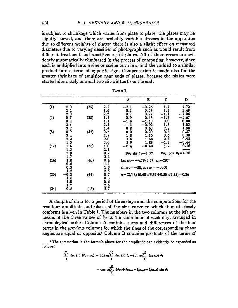
is subject to shrinkage which varies from plate to plate, the plates may beslightly curved, and there are probably variable stresses in the apparatusdue to different weights of plates; there is also a slight effect on measureddiameters due to varying densities of photograph such as would result fromdifferent treatment and sensitiveness of plates. All of these errors are evidently automatically eliminated in the process of computing, however, sinceeach is multiplied into a sine or cosine term in fJ, and then added to a similarproduct into a term of opposite sign. Compensation is made also for thegreater shrinkage of emulsion near ends of plates, because the plates werestarted alternately one and two slit-widths from the end.
TABLB I.
A B C D
(1) 2.0 (25) 2.2 -2.1 -0.26 1.7 1.702.4 1.6 0.1 0.03 1.5 1.492.0 2.2 0.7 0.27 -1.1 -1.06
(4) 0.7 (28) 1.1 0.9 0.45 -1.7 -1.670.2 1.1 -1.8 -1.10 0.0 0.002.1 2.1 -1.3 -0.92 1.3 1.033.2 1.4 0.8 0.63 2.8 1.98
(8) 0.9 (32) 0.6 0.0 0.00 0.6 0.373.4 2.2 1.8 1.56 0.6 0.302.0 0.0 1.6 1.48 2.4 0.921.0 0.9 1.9 1.83 -1.7 -0.44
(12) 1.4 (36) 1.0 -0.4 -0.40 1.2 0.161.3 2.12.0 0.2 ~u, sin 8, ==3.57 1:u, cos 8,=:4.781.7 2.1
(16) 1.0 (40) 0.4 tan~a== -4.78/3.57, 611=-207°0.8 1.10.3 1.3 sinwl= -80, COS~2=+0.601.2 2.5
(20) -0.2 (44) 0.7 Q, =r (2/48) (0.60 X3.57 +0.80 X4.78) ==0.261.6 0.31.5 0.61.7 2.4
(24) 0.8 (48) 2.7
A sample of data for a period of three days and the computations for theresultant amplitude and phase of the sine curve to which it most closelyconforms is given in Table I. The numbers in the two columns at the left aremeans of the three values of 8p at the same hour of each day, arranged inchronological order. Column A contains sums and differences of the fourterms in the previous columl1S for which the sines of the corresponding phaseangles are equal or opposite:' Column B contains products of the terms of
4 The sunlmation in the formula above for the amplitude can evidently be expanded asfollows:
m " "L 8PI sin (6, - ~I) == cos Cd2L 8", sin (Ji - sin CaJ2L 8pe cos 0,1 1 1
11
== cos 6)JL (8p,+6p2&-I- 8P24+' - 8p49-1) sin 0,1
RELATIYITY OF TIMB 4:15
column A into the sines of the corresponding phase angles. Columns C alldD contain the corresponding qualltities to A and B, using the cosine illsteadof the sine.
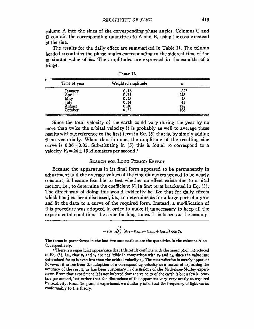
1"he results for the daily effect are summarized ill Table II. l'lle columnheaded w contains the phase angles corresponding to the sidereal time of tIlemaximum value of 8n. The amplitudes are expressed in thousandtlls of afringe.
TABLE II.
Time of year Weighted amplitude ~
January 0.16 89°April 0.27 273May 0.18 18July 0.14 43August 0.30 128October 0.22 183
Since the total velocity of the earth could vary during the year by nomore than twice the orbital velocity it is probably as well to average theseresults without reference to the first term in Eq. (5) that is, by simply addingthem vectorially. When that is done, the amplitude of the resulting sillecurve is 0.06 ±0.05. Substituting in (5) this is found to correspond to avelocity V~ == 24 ±19 kilometers per second.I
SEARCH FOR LONG PERIOD EFFECT
Because the apparatus in its final form appeared to be permanently inadjustment and the average values of the ring diameters proved to be 11earlyconstant, it became feasible to test whether an effect exists due to orbitalmotiol1, i.e., to determine tile coefficient VQ in first term bracketed in Eq. (5).The direct way of doing this would evidently be like that for daily effectswhicl1 has just been discussed, i.e., to determine an for a large part of a yearand fit tIle data to a curve of the required form. Instead, a Inodification ofthis procedure was adopted in order to make it. unnecessary to keel) all theexperimental conditions the same for long times. It is based on the assump-
11
- sin Cl)JE (8p,-8pu-,-BpH+l+ap4t-,) cos 0,.I
The terms in parentheses in the last two summations are the quantities in the COlUlllDS A allC. respectively.
i There is a superficial appearance that this result conflicts with the assuI11ptioll intl·oducedin Eq. (5), i.e., that Vl and tl2 are negligible in comparison with tla and rJ{J, since the value justdeterillined for 'IJ(J is even less than the orbital velocity VI. Tbe contradiction is nlerely apparenthowever; it arises from the adoption of a corresponding velocity as a nleans of expressing theaccuracy of the result, as has been customary in discussions of the Michelson-Morley experi.ment. Froln that experiment it is not inferred that the velocity of the earth is but a few kilometers per second, but rather that the dimensions of the apparatus vary very nearly as requiredby relativity. From the present experiment we similarly infer that the frequency of light variesconformably to the theory.

416 Il. J. KENNEDY AND E. M. THORNDIKE
tioD that the most probable rate of variation of an (computed from measuredvalues of Bp over short times) is equal to the derivative of the most probablefirst term in Eq. (5). Each of tllree series of data, taken for periods varyingfrom eight days to a month, and at intervals of tllree montlls, was used tocompute the daily rate of change of p8 at those times of year. This rate wasfound by averaging arithmetically the readings of eacl1 day of a given seriesand determining by the method of least squares the slope of the most probable straight line represel1ted by them. Similarly the most probable sinecurve corresponding to these three derivatives is computed. Some 300 exposures cOlnprised the three series.
'"rhe three computed rates of cl1ange were 0.050 ±0.020, 0.007 ±0.013 and-0.015 ±O.021, all expressed in thousandths of a fringe per day. The com..puted sine curve has an amplitude of 2.96 thousandths and this correspondsto a velocity VII == 15 ±4 km per sec. Since the relatively small probable erroris based only on the illternal consistency of the data al1d is therefore notto be taken very seriously, this result can scarcely be regarded as indicatinga real velocity. Furtl1ermore the direction of the computed velocity is 1230
away from that computed above.As we have used only 300 exposures in the applicatiol1 of tllis method, it
is evident that the accuracy could be increased by a large factor if data weretaken steadily for a few months. The proverbial brevity of life, however,argues against laboring the POill t.
If the last result and that for the rotational effect are given the sameweight and combined vectorially (ignoring difference of direction of Va andVIJG their resultant is 10 ±10 km per sec. In view of relative velocitiesamounting to thousands of kilometers per second kl10wn to exist among thenebulae, this can scarcely be regarded as other than a clear null result; it isof the same order of precision as that of tIle Michelson-Morley experimeJlt.It is perhaps best expressed as at present in terms of a velocity, although ofcourse the conclusion to be drawn is that the frequency of a spectral linevaries ill the way required by relativity.? This appears to be the OIlly investigation in which a quantum phenomenon is shown to conform to Einstein's theory.
Insofar as the radiating atom may be regarded as a typical clock, the result of this experiment can be combined with assumption (b) to derive theLorentz-Einstein transformations. Throughout the foregoing discussion wehave dealt with time regarded as measured only at a fixed place in the movingsystem Sj in order to specify unambiguously the time at another point ofS it is necessary to specify the operations which define it. Perhaps the Dl0st
natural meaning to attach to the concept is that the time at any point is theindicatiol1 of a clock which has been Inoved with infinitesimal velocity to the
e The two results can be combined only by making some approximation.7 It is of course altogether possible that there is a real (inherently observable) velocity
which is so nearly perpendicular to the orbital and equatorial planes as to have componentsin them small enough to have escaped observation, but the probability seems small in view ofthe nebular velocities nlentioned above.

RELA. TIVITY OF TIME 417
point, and from the same location as an identical clock with whicl1 it wasoriginally in agreement; it turns out that this definition is equivalent to thatof synchronizing by means of light signals.
We have shown that the frequency 'P' of an atom moving with velocityf} bears the relation p' == (1-7)I/C2)1/2" to that of a fixed atom. Let us assumethat the indications of clocks under similar conditions bear the same ratio.Suppose that at time e=t'=o, the origins of parallel coordinates in Sand 8'(previously defined) coincide, and that the S-clock passes through tIle originwith a small velocity with respect to S. Because of this motion, the velocityof the clock with respect to S' will have components, say, fJ+u~, u" u.; hencethe times t' and t indicated by a clock in S' and the clock in S will thereafterstand in the relation
'[ (!1 + U:r)2 + U,,2 + Ua2J1 /
2 [ , ( VI) 2t'2U##'O , J1/2e -== e 1 - = t" - - - --- - t IU2 •c2 c' CS
Now u:et' is equal to S'-measure of distance x traversed in S by the clock;hence use' =: (l-rJ'/C'J.)l/'lX. If this is substituted in the second term of theright side of the above equation and u is made to approach zero,
[, ( 7)2) 2fJxt' ( f)t)1/2Jl/~
t= t 2 1-- --- 1--c2 c2 c2
and so
I' = 1 [!IX + t (1 +~ X2)1/
2J.(1 - '1)2/c2) t/2 c2 c4 fA
Here xl' is the velocity of clock with respect to S, and it approaches zerowith Uj hence the coefficient of I in the last expressioll is unity, and
(11)
The statement that the systems are in uniform relative velocity, togetherwith fact that t' is independent of y and z implies
x' = x'(x + 'De) ; hence ax'lox = (1/'IJ) (ax'lat). (12)
The measurement in S' of the lenth of an interval as in S is obtained byobserving the distance 6s' between points in S' with Wl1ich the ends of theinterval coincide at same S'-time. For measurement alol1g x' axes we have,because of Lorentz-Fitzgerald contraction
ax' ax' ( V2)1/2ax' =-8x + - 61 == 1 - - ax
ax at c2
when
3t' == 1 (3t + !.-ax) = 0, i.e.,(1 - f)'/C2)1/'J c2

418 R. J. KENNEDY AND E. M. THORNDIKE
when 8t= - ('O/c2)8x. Hence
ax' fJ ax ( V2)1/1
-8x-- --6x = 1-- 8x.ax c2 at c2
From this and (12)
a~ 1 a~ v- = and - == -----ax (1 - '02/C2)1/1 ae (1 - '1)1/,2)1/2
Hence
x' = (1 - 'i}'J/ct)-1/2(X + 71t).
This equation and (11) together with y' =y, s' =s, are the Lorentz-Eil1steintransformationsj because they are known to possess the group property, thesystem S' which has been used as a tentative standard of reference evidentlyloses all trace of uniqueness.
The research set forth in this paper has been carried on over a period ofseveral years, during which many obligations have been incurred. Preliminarywork on it served as basis for the senior author's doctoral thesis at JOhllS
Hopkins University. The main work was done at the California Institute ofTechnology with the aid of fellowships granted by the National ResearchCouncil, the Guggenheim Memorial Foundation and the Institute; it wascompleted during leave of absence granted by the University of Washington.Particularly acknowledgment is made to Professors E. T. Bell, R. C. Tolman and R. A. Millikan, whose interest and encouragement have made thework possible, and to Mr. Juliu's Pearson to whom several essential refinements of the apparatus are due.