EXPERIMENTAL DETERMINATION OF BEAM QUALITY CORRECTION FACTORS IN
46
EXPERIMENTAL DETERMINATION OF BEAM QUALITY CORRECTION FACTORS IN CLINICAL HIGH-ENERGY PHOTON AND ELECTRON BEAMS Moses Fredrick Katumba A research report submitted to the Faculty of Science, University of the Witwatersrand, Johannesburg, in partial fulfillment of the requirements for the degree of Master of Science. OCTOBER 2010.
Transcript of EXPERIMENTAL DETERMINATION OF BEAM QUALITY CORRECTION FACTORS IN

EXPERIMENTAL DETERMINATION OF BEAM QUALITY CORRECTION FACTORS
IN CLINICAL HIGH-ENERGY PHOTON AND ELECTRON BEAMS
Moses Fredrick Katumba
A research report submitted to the Faculty of Science, University of the Witwatersrand,
Johannesburg, in partial fulfillment of the requirements for the degree of Master of Science.
OCTOBER 2010.

i
DECLARATIO
I declare that this research report is my own, unaided work. It is being submitted for the degree
of Master of Science in the University of the Witwatersrand, Johannesburg. It has never been
produced before for any degree or examination in any other University.
Moses Fredrick Katumba
13 October 2010
ii
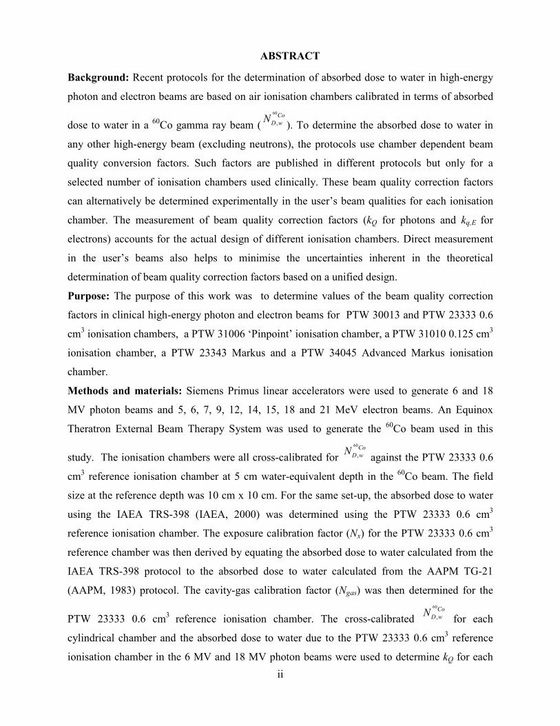
ABSTRACT
Background: Recent protocols for the determination of absorbed dose to water in high-energy
photon and electron beams are based on air ionisation chambers calibrated in terms of absorbed
dose to water in a 60Co gamma ray beam (
60
,
Co
D w�
). To determine the absorbed dose to water in
any other high-energy beam (excluding neutrons), the protocols use chamber dependent beam
quality conversion factors. Such factors are published in different protocols but only for a
selected number of ionisation chambers used clinically. These beam quality correction factors
can alternatively be determined experimentally in the user’s beam qualities for each ionisation
chamber. The measurement of beam quality correction factors (kQ for photons and kq,E for
electrons) accounts for the actual design of different ionisation chambers. Direct measurement
in the user’s beams also helps to minimise the uncertainties inherent in the theoretical
determination of beam quality correction factors based on a unified design.
Purpose: The purpose of this work was to determine values of the beam quality correction
factors in clinical high-energy photon and electron beams for PTW 30013 and PTW 23333 0.6
cm3 ionisation chambers, a PTW 31006 ‘Pinpoint’ ionisation chamber, a PTW 31010 0.125 cm
3
ionisation chamber, a PTW 23343 Markus and a PTW 34045 Advanced Markus ionisation
chamber.
Methods and materials: Siemens Primus linear accelerators were used to generate 6 and 18
MV photon beams and 5, 6, 7, 9, 12, 14, 15, 18 and 21 MeV electron beams. An Equinox
Theratron External Beam Therapy System was used to generate the 60Co beam used in this
study. The ionisation chambers were all cross-calibrated for
60
,
Co
D w�
against the PTW 23333 0.6
cm3 reference ionisation chamber at 5 cm water-equivalent depth in the
60Co beam. The field
size at the reference depth was 10 cm x 10 cm. For the same set-up, the absorbed dose to water
using the IAEA TRS-398 (IAEA, 2000) was determined using the PTW 23333 0.6 cm3
reference ionisation chamber. The exposure calibration factor (�x) for the PTW 23333 0.6 cm3
reference chamber was then derived by equating the absorbed dose to water calculated from the
IAEA TRS-398 protocol to the absorbed dose to water calculated from the AAPM TG-21
(AAPM, 1983) protocol. The cavity-gas calibration factor (�gas) was then determined for the
PTW 23333 0.6 cm3 reference ionisation chamber. The cross-calibrated
60
,
Co
D w�
for each
cylindrical chamber and the absorbed dose to water due to the PTW 23333 0.6 cm3 reference
ionisation chamber in the 6 MV and 18 MV photon beams were used to determine kQ for each

iii
ionisation chamber at the respective photon energies. The plane-parallel and the cylindrical
ionisation chambers were then cross-calibrated for �gas in the 21 MeV electron beam. The
absorbed dose to water in the electron beams was then calculated from first principles using the
AAPM TG-21 worksheets for all of the chambers. The kq,E were then derived for each of the
ionisation chambers at each of the electron energies.
Results: The measured kQ values as a function of TPR20,10 (the tissue-phantom ratio in water at
depths of 20 cm and 10 cm, for a field size of 10 cm x 10 cm and a constant source-chamber
distance of 100 cm) for the different ionisation chambers and the published IAEA TRS-398 kQ
values for the PTW 30013 0.6 cm3 ionisation chamber are tabulated below:
ominal
energy/MV
TPR20,10 PTW
23333
PTW
31006
PTW
31010
PTW
30013
PTW 30013
(IAEA TRS-398)
6 0.674 0.991 0.998 0.997 0.993 0.991
18 0.770 0.973 0.973 0.985 0.973 0.972
The measured kq,E values as a function of R50 for the electron beam qualities for the different
ionisation chambers and the published IAEA TRS-398 kq,E values for the PTW 23343 Advanced
Markus ionisation chamber are tabulated below:
ominal
Energy
(MeV)
R50/
cm
PTW
23333
PTW
30013
PTW
31006
PTW
31010
PTW
34045
PTW
23343
PTW 23343
(IAEA
TRS-398)
5 2.05 0.890 0.899 1.035 0.877 0.950 0.917 0.925
6 2.40 0.884 0.890 1.023 0.872 0.946 0.915 0.921
7 2.75 0.878 0.884 1.022 0.870 0.946 0.917 0.918
9 3.51 0.868 0.873 1.002 0.862 0.926 0.900 0.913
12 4.68 0.858 0.859 0.988 0.864 0.912 0.891 0.906
14 5.28 0.851 0.854 0.978 0.859 0.904 0.885 0.902
15 5.93 0.851 0.852 0.978 0.851 0.895 0.893 0.899
18 7.30 0.859 0.861 0.986 0.861 0.893 0.899 0.893
21 8.23 0.820 0.824 0.932 0.822 0.847 0.850 0.888
The average observed difference between the measured values and those published in the IAEA
TRS-398 protocol was 0.2% for the PTW 30013 0.6 cm3 in the photon beams and 1.2% for the
PTW 23343 Markus ionisation chamber in the electron beams.
Conclusion: Beam quality correction factors for ionisation chambers can be determined
experimentally or confirmed in an end-user’s beam quality.
iv
DEDICATIO
To JJaaja Elios Nakisozi
(1926-2006)
v
ACKOWLEDGEMETS
I greatly appreciate the Divisions of Radiation Oncology and Medical Physics of the Charlotte
Maxeke Johannesburg Academic Hospital for the use of their facilities.
I am grateful for the sacrifice of my supervisor Professor D. G. Van der Merwe, for her endless
encouragement and guidance throughout the entire research. I hereby also acknowledge her
expertise, enthusiasm and skill in the field of medical radiation physics that has made me what I
am in the field of Medical Physics. I would like to appreciate her financial assistance towards
research in the medical physics fraternity in Africa.
I am thankful to Dr E.S.K. Mugambe, Mr Peter Ddungu Matovu, Dr Awusi Kavuma, Dr Joseph
K. Mugambe for advising, encouraging and providing the scholarship to pursue a career in
medical radiation physics.
I am extremely indebted to the IAEA for the financial assistance during training and during the
carrying out of this research and report writing. I mention particularly my contact person at the
IAEA, Ms Thoko Mueller and Mr Dan Mothauli and Mr Bongani Nogemane at NECSA for they
were always good to me whenever I called them regarding the stipend and re-imbursements
from IAEA.
Heartfelt thanks are also extended to Mr Samuel J. Ssebaggala, Dr Ezra M. Twesigomwe, Mr
Labison K Ssemambo, Mr Livingstone Kalinge and Mr Elias Mugisha for their love and support
of my education.
I am grateful too for the immeasurable efforts of Mr Wanyama and Mr Mutebi who with
untiring energy guided me through the early years of my education.
I recognize the support that I have received from Mr M. A. Maphophe, Mr M. O. Akapchafor
and other colleagues whose presence greatly, morally influenced the pace of and direction of
this piece of work.
I thank Mr Leonard Lukenge for providing me computer support whenever needed.
Ms Flavia Naluyinda has been so good in calming me down whenever my spirit gave way. She
has been a superb advisor, and a lovely companion.

vi
TABLE OF COTETS
DECLARATIO .............................................................................................................. i
ABSTRACT ..................................................................................................................... ii
DEDICATIO ................................................................................................................ iv
ACKOWLEDGEMETS ............................................................................................ v
TABLE OF COTETS ................................................................................................ vi
LIST OF TABLES ........................................................................................................ viii
LIST OF FIGURES ........................................................................................................ ix
DEFIITIO OF TECHICAL TERMS, ACROYMS AD SYMBOLS. ............... x
CHAPTER OE: ITRODUCTIO
1.1 Introduction ………………………………………..…………………………......……..…..1
1.2 Background to the problem ………………………….………………………………….…..1
1.3 Statement of the problem ……………………………..……………………………....…….2
1.4 Objectives of the study…………………………………..………………………….….…...3
CHAPTER TWO: LITERATURE REVIEW
2.1 Photon beam dosimetry……………………………………….……………………......……4
2.2 Electron beam dosimetry……………………………………………………………..…..…5
2.3 Beam quality specification…………………………………………………………..............5
2.3.1 Photon beam quality specification………………………………...........….…..6
2.3.2 Electron beam quality specification…………………………….….............…..7
2.4 Theoretical expressions for the beam quality correction factors in high energy photons and
electron beams……………….………………………..………………………………………….8
2.4.1 Theoretical expression for kQ (photon beams)..……..............…………….……8
2.4.2 Theoretical expression for kq,E (electron beams)……..…...........………………9
2.5 Reference conditions of the irradiation geometry for absorbed dose measurements using an
ionisation chamber in a phantom………………………………….….…………………...….…10
CHAPTER THREE: MATERIALS AD METHODS
3.1 The Charlotte Maxeke Academic Hospital Johannesburg linear accelerator.
……………………………………………………………………………………...…..……….11

vii
3.2 The Theratron Equinox External Beam Therapy System. ……………………………….... 12
3.3 Ionisation chambers …………………………………….……………………………..……13
3.4 Perspex phantom………………………………..………………….……………………..…16
3.5 Other materials used……………………………………………………………...…………17
3.6 The cross-calibration of ionisation chamber in photon and electron beams …………….…17
3.6.1 Cross-calibration of the
60
,
Co
D w�for ionisation chambers in
60Co beam………..........…18
3.6.2 Cross-calibration of the 60Co exposure calibration factor �x’s……………...........…18
3.6.3 Cross-calibration of the �gas for plane-parallel chambers in electron beams
……………………………………………………………………………………….....……….19
3.7 The absorbed dose measurement in megavoltage photon beams ……………..………..…..19
3.8 The absorbed dose measurement in electron beams……………………………..……….…20
3.9 Determination of beam quality correction factors………………….………..………...……21
CHAPTER FOUR: RESULTS AD DISCUSSIOS
4.1 The results of the cross-calibration of the ionisation chambers....……………………..……22
4.2 Measurement results in 6 MV and 18 MV photon beams…………………………….....….23
4.3 Measurement results in the electron beam qualities ……………………….………….……25
CHAPTER FIVE: COCLUSIOS AD RECOMMEDATIOS …………….………29
REFERECES……………………………………………………………………...…………31

viii
LIST OF TABLES
Table 3.1: The PTW 23333 reference ionisation chamber calibration factor history ............... 13
Table 3.2: The uncertainty budget of �x and �gas of the ionisation chambers used in this
study.…………………..…………………….……………………….........………………..…. 13
Table 3.3: The characteristics of the different ionisation chambers types used in this
study……………………………………...………………………………………………..….. 15
Table 3.4: Beam characteristics for the clinical electron beams and the mean restricted collision
mass stopping power of perspex to air used in this study….................................................…. 20
Table 4.1: The absorbed dose to water calibration factors for the ionization chambers used in
this study…………………………………………………………....……………………...…..21
Table 4.2: The results of �x and �gas calibration factors for the ionization chambers used.
………………………………………………………………………………………………….22
Table 4.3: The measured kQ as a function of TPR20,10 of the various ionisation chambers used in
this study………………………………………………………...........……..…..…….…..……23
Table 4.4: Summary of the doses in Gy per 100 monitor units at dmax using each of the
ionization chambers………………………………………………………….………………….24
Table 4.5: The replacement correction factors for the cylindrical ionisation chambers at each
electron beam quality and the replacement correction factors published by Khan (2003) for the
PTW 23333 0.6 cm3, as used for absorbed dose determination in the electron beams
…………………………………………………..….........……………...………..………….….25
Table 4.6: The calculated ,
,
q E
D w� in x 107 Gy/C at each electron energy for the various
ionisation chambers. ……………………………………………………………...…………….26
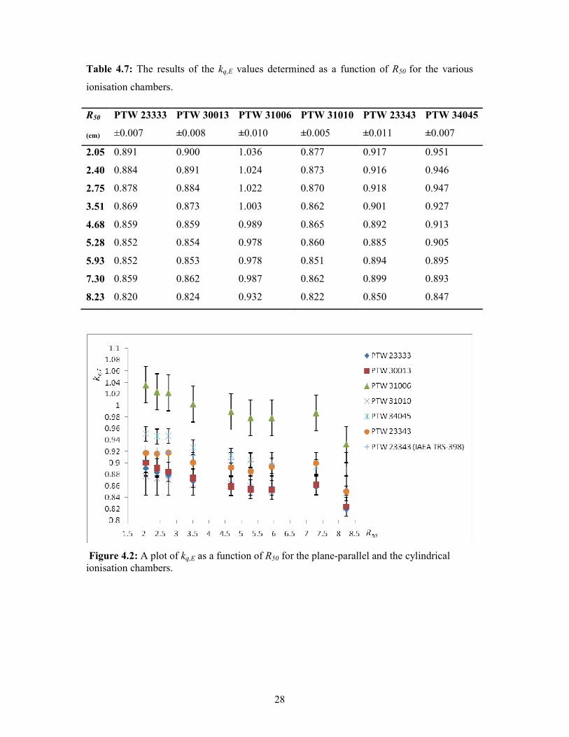
Table 4.7: The results of the determined kq,E values as a function of R50 for the various
ionisation chambers……………………………………………………………...…….………..27

ix
LIST OF FIGURES
Figure 3.1: A Siemens PRIMUS linear accelerator used in this study…….…….……….…11
Figure 3.2: The Theratron EquinoxTM
External Beam Therapy System used in this
study……………………………………………………………………………………….....12
Figure 3.3: The pictorial representation of the apparatus used in this study. (a) The PTW 23333
0.6 cm³ chamber/ PTW 30013 0.6 cm³ chamber, (b) The PTW 31010 0.125 cm³ chamber (c)
The PTW 31006 ‘Pinpoint’ 0.015 cm³ chamber (d) The PTW 34045 0.02 cm³ Advanced Markus
chamber/ PTW 23343 0.055 cm3 Markus chamber..................................................................16
Figure 3.4: The PTW T10008 Unidose E Electrometer ……………….………...………..….17
Figure 4.1: A plot of kQ values from this work for PTW 23333 0.6 cm3, PTW 30013 0.6 cm
3,
PTW 31006 ‘Pinpoint’ and PTW 31010 0.125 cm3 and those published in the IAEA TRS-398
for PTW 23333 0.6 cm3 and PTW 30013 0.6 cm
3 as a function of
TPR20,10…………………………………………………………………………………....….24
Figure 4.2: A plot of kq,E as a function of R50 for the plane-parallel and the cylindrical ionisation
chambers ……………………………..…………………………...………………….……….28

x
DEFIITIO OF TECHICAL TERMS, ACROYMS AD SYMBOLS.
AAPM American Association of Physicists in Medicine.
ARPANSA Australian Radiation Protection and Nuclear Safety Agency.
TG Task Group.
AAPM TG-21 A protocol of the AAPM TG-21 for the determination of absorbed dose
from high-energy photon and electron beams.
IAEA International Atomic Energy Agency.
TRS Technical Report Series.
IAEA TRS-398 An international code of practice for the absorbed dose determination in
external beam radiotherapy, published by the IAEA on its own behalf, and
on behalf of the World Health Organisation (WHO), the Pan Ameraican
Health Organisation (PAHO) and the European Society of Therapeautic
Radiology and Oncology (ESTRO).
Eo The mean electron energy of the incident spectrum striking the phantom
surface.
E The mean energy of an electron beam at any depth.
MV Megavoltage.
Q The beam quality in the user’s photon or electron beam for which clinical
reference dosimetry is performed. For photon beams it is in terms TPR20,10
and for electron beams, in terms of R50. However, in this report Q is used
exclusively for photon beams and q,E is for electron beams.
SAD Source-axis distance.
SSD Source-surface distance.
TPR Tissue phantom ratio.

xi
NAP Nominal accelerating potential.
qecal An arbitrary electron beam quality taken as R50= 7.5 cm. It is introduced to
simplify the factors needed in electron beam dosimetry in IAEA TRS-398.
TPR 20,10 The ratio of doses on the beam central axis at depths of 20 cm and 10 cm
in a water phantom, obtained with a constant source-chamber distance of
100 cm and a field size of 10 cm x 10 cm at the plane of the chamber.
60
,
Co
D w� The absorbed dose to water calibration factor (in Gy/C) for the ionisation
chamber in the reference 60Co beam.
,
,
q E
D w�
The absorbed dose to water calibration factor (in Gy/C) for the ionisation
chamber in an electron beam of quality q,E.
kQ A chamber specific factor which corrects the absorbed dose to water
calibration factor in a 60Co beam to another photon beam of quality Q.
kq,E ,q Ek is a beam quality conversion factor for electrons to convert
60
,
Co
D w� to
,
,
q E
D w�for an electron beam of quality q,E. In this report, the notation ,q Ek
is adopted for electron beam qualities to distinguish it from kQ for photon
beam qualities.
kecal The photon to electron conversion factor defined for a given chamber
model that converts the absorbed dose to water calibration factor at 60Co
to the absorbed dose to water calibration factor in the electron beam of
quality qecal.
50
'
Rk The electron quality conversion factor used to convert ,
ecalq
D w�into the
absorbed dose to water calibration factor ,
,
q E
D w�for any electron beam of
quality q,E.
Dw The absorbed dose to water for a particular set up and monitor units.

xii
MU The number of monitor units or time for which a given irradiation is
performed.
Pcav Factor that corrects the response of an ionisation chamber for effects
related to the air cavity ; predominately the in-scattering of electrons that
makes the electron fluence inside a cavity different from that in the absence
of the cavity.
Pgr Corrects for the gradient effects at the reference depth when a cylindrical
chamber is used in an electron beam, and depends on the ionisation
gradient at the point of measurement.
SSDL Secondary Standards Dosimetry Laboratory.
BIPM Bureau International de Poids et Mesure, Paris.
PTB Physikalisch-Technische Budesanstalt.
PTW Physikalisch Technische Werkstätten.

1
CHAPTER OE: ITRODUCTIO
1.1 Introduction
The International Atomic Energy Agency and the American Association of Physicists in
Medicine are among the various organisations that have published dosimetry protocols and
Codes of Practice for the calibration of radiotherapy beams (Pedro & Saiful, 2001).
Currently an ionisation chamber, calibrated in terms of the absorbed dose to water in a 60
Co
gamma ray beam, is used to determine the dose in a medium. The rationale of this trend is
to deal directly with absorbed dose to water, a quantity which relates closely to
radiobiological effects in humans and is therefore of interest in the clinic (IAEA, 2000).
This approach offers the possibility of reducing the uncertainty in dosimetry compared to
air kerma based formalisms, provides a robust system of primary standards with
dissemination and allows the use of a simple formalism (IAEA, 2000; Pedro & Saiful,
2004; Saiful, 2001). The formalism and dosimetry procedures use the absorbed dose to
water calibration factor of an ionisation chamber at 60
Co ( )60
,
Co
D w� together with a theoretical
beam quality conversion factor (Qk for photons or kq,E electrons) for the determination of
absorbed dose to water in other high-energy beams excluding neutrons (IAEA, 2000;
Saiful, 2001). The absorbed dose to water in a 60
Co gamma ray beam is therefore an
international reference standard, which provides global uniformity in radiotherapy
dosimetry. This study aimed at determining the beam quality correction factors for several
different ionisation chambers, which could be used in the measurement of absorbed dose to
water in high-energy photon and electron beams at the Charlotte Maxeke Johannesburg
Academic Hospital.
1.2 Background to the problem
Measurements in radiotherapy dosimetry are either relative or absolute. In absolute
dosimetry, the physical quantity is measured at the reference point under reference
conditions to yield the absorbed dose to water at the reference point (European Medical
Radiation Learning Development, 2001).
It is imperative to determine dose as accurately and precisely as possible in order to deliver
the prescribed dose to a point or a given volume of interest (AAPM, 1983). There are
2
different parameters that enter into the formalisms for determination of absorbed dose to
water. These physical quantities need to be studied carefully and accurately in order to
determine the absorbed dose to water within uncertainties of ±3.5% or better (IAEA, 2000).
It is known for example, that the relative uncertainty of ionometric determinations of
absorbed dose to water in reference dosimetry of high-energy photon beams is dominated
by the uncertainty of the calculated chamber- and energy-dependent correction factors, Qk
(Achim & Ralf-Peter, 2007).
Many reviewers (Hugo et al., 2002; Podgorsak, 2005; Rogers, 1990) recommend that the
beam quality correction factors for megavoltage radiotherapy beams are measured directly
in the user’s beam for each ionisation chamber. Often these factors are calculated
theoretically from data available in different protocols. It is known that Qk can be measured
with a standard uncertainty of less than 0.3% (Achim & Ralf-Peter, 2007; IAEA, 2000;
Saiful, 2001).
The experimental determination of Qk and ,q Ek at various beam qualities intrinsically takes
into account the response of different ionisation chambers. In contrast, the calculated values
of Qk ignore chamber-to-chamber variations in response to energy within a given chamber
type, and its uncertainty is therefore larger than for experimentally determined Qk values
(Saiful, 2001). Direct calibration, in terms of absorbed dose to water at each beam quality,
reduces the total uncertainty of absorbed dose determination in the user’s beam by 1–1.5%
(Hugo, Wim & Hubert, 1999). This study aimed at determining the beam quality correction
factors for several different ionisation chambers used for the dosimetry of high-energy
photon and electron beams at the Charlotte Maxeke Johannesburg Academic hospital.
1.3 Statement of the problem
Many reviewers recommend that the beam quality correction factors for radiotherapy
megavoltage beams are measured directly in the user’s beam for each ionisation chamber.
Can the beam quality correction factors of different ionisation chambers at different high-
energy photon and electron beams be determined accurately in a clinical set up?

3
1.4 Objectives of the study
The primary aim of this study is to experimentally determine the Qk and ,q Ek factors for
different ionisation chambers in a range of high-energy photon and electron beams used at
the Charlotte Maxeke Johannesburg Academic hospital. The specific aims of the study
were fourfold;
• Cross-calibrate the PTW 30013 0.6 cm3 ionisation chamber, a PTW 31006
‘Pinpoint’ ionisation chamber, a PTW 31010 0.125 cm3 ionisation chamber, a PTW
23343 Markus and a PTW 34045 Advanced Markus ionisation chamber against a
PTW 23333 0.6 cm3 reference ionisation chamber which has a traceable calibration.
• Determine the absorbed dose-to-water in a range of photon and electron beams
using IAEA TRS-398 with the PTW 23333 0.6 cm3 reference ionisation chamber
with 60
,
Co
D w� and
60Co
k�calibration factors of proven stability and traceability and
IAEA TRS-398 published Qk and ,q Ek
values.
• Measure the response of the PTW 30013 0.6 cm3 ionisation chamber, the PTW
31006 ‘Pinpoint’ ionisation chamber, and the PTW 31010 0.125 cm3 ionisation
chamber in the photon beams.
• Measure the response of the PTW 30013 0.6 cm3 ionisation chamber, the PTW
31006 ‘Pinpoint’ ionisation chamber, the PTW 31010 0.125 cm3 ionisation
chamber, the PTW 23343 Markus and the PTW 34045 Advanced Markus ionisation
chamber in the electron beams.
• Compare the experimentally determined values of Qk and ,q Ek with published ones
for the PTW 30013 0.6 cm3 and PTW 23343 Markus ionisation chambers,
respectively.
• Derive Qk and ,q Ek for the PTW 31010 0.125 cm3, PTW 31006 ‘Pinpoint’ and PTW
34045 Advanced Markus models of ionisation chambers for which published data
do not exist.
4
CHAPTER TWO: LITERATURE REVIEW
2.1 Photon beam dosimetry
The absorbed dose to water Dw, at a reference depth in a photon beam of quality Q, and in
the absence of an ionisation chamber is determined from:
60
,. . . ,Co
w D w Q iD M � k k= ∏ ………............................................................ (1)
where
• M is the charge measured under standard conditions of temperature, pressure and
humidity.
• 60
,
Co
D w�is the absorbed dose to water calibration factor (in Gy/C) for the ionisation
chamber in the 60
Co reference beam.
• Qk is a chamber specific factor which corrects
60
,
Co
D w�to the user’s beam quality Q
(different from the 60Co beam).
• ik∏ is the product of the factors to correct for non-reference conditions in the setup
and incomplete ion collection efficiency of the ionisation chamber ( Rogers, 1990).
Factors ki represent a correction for the effect of i-th influence quantity. Such
correction factors may have to be applied as the calibration coefficient refers,
strictly speaking, only to reference conditions. By definition, the value of ki is unity
when influence quantity i, assumes its reference value (Rogers, 1990).
The product
60
, ,. ( )Co Q
D w Q D w� k �= is of special interest and is the absorbed dose to water
calibration factor (in Gy/C) of the ionisation chamber in the beam quality Q. The current
accepted relative uncertainty of Dw in equation (1) is of the order of 1.5% as determined by
ionometric methods and the uncertainty in kQ is 1% (Achim & Ralf-Peter, 2007).
5
2.2 Electron beam dosimetry
According to AAPM TG-51(Almond et al., 1999), the absorbed dose to water in an electron
beam of quality q,E is given by;
60,
, ,. .q E Co
w D w q ED M � k=................................................................................................ (2)
where
• M is the reading of the dosimeter with the point of measurement of the chamber
positioned at the reference depth under reference conditions and corrected for ion
recombination, polarity effect, electrometer correction factor and the standard
environmental conditions of temperature, pressure and relative humidity of the air in
the ion chamber.
• 60
,
Co
D w� is the absorbed dose to water calibration factor (in Gy/C) of the ionisation
chamber in the reference 60
Co beam.
• ,q Ek is a beam quality conversion factor for electrons to convert
60
,
Co
D w� to
,
,
q E
D w� for
an electron beam of quality q,E.
2.3 Beam quality specification
Among the difficulties of the kQ and kq,E concept is the need for a unique beam quality
specification and the possible variation in the kQ and kq,E values for different chambers of
the same type (Hugo, Wim & Hubert, 1999). The AAPM TG-21 (AAPM, 1983) protocol
specifies photon beam energy in terms of the energy of the electron beam as it strikes the
target (the nominal accelerating potential) which is related to the “ionisation ratio”. The
ionisation ratio is defined as the ratio of the ionisation charge or dose measured at 20 cm
depth in water to that measured at 10 cm depth for a constant source to detector distance in
a 10 cm x 10 cm field at the plane of the chamber. The ionisation ratio is the same as the
TPR20,10 expression used by the IAEA TRS-398 (IAEA, 2000)dosimetry protocol. The
ionization ratio or TPR20,10 is a measure of the effective beam attenuation coefficient
through 10 cm of water. TPR20,10 is empirically related to the percentage depth dose,
through
20,10 20,101.2661 0.0595TPR PDD= − …………………………………………………… (5)

6
where PDD20,10 is the ratio of percentage depth doses at 20 cm and 10 cm depths for a field
size of 10 cm x 10 cm field size defined at the water phantom surface with a source to
surface distance of 100 cm ( IAEA, 2000; Podgorsak, 2005).
When linear accelerator electron beams strike a phantom or a patient surface at the nominal
SSD, a spectrum results from the energy spread. This is caused by interactions within the
air and with the linear accelerator components like the collimators, scattering foil, monitor
chamber and applicator. The electron beam is therefore degraded and contaminated. The
quality of clinical electron beams has been specified as Eo, the mean electron energy of the
incident spectrum striking the phantom surface (Podgorsak, 2005). Eo is empirically
derived from R50, the depth at which the electron beam depth dose decreases to 50% of its
maximum value (IAEA, 2000). The reference depth dref, for electron beam calibrations in
water is expressed as
dref (cm) = 0.6R50 (cm) - 0.1 (cm) …………………………………..…………………….. (6)
The reference depth dref is used clinically because it is known to significantly reduce
machine to machine deviations in chamber calibration coefficients (Hugo et al., 2002).
2.3.1 Photon beam quality specification
The use of ionisation ratios for the determination of photon beam quality indices provides
an acceptable accuracy owing to the slow variation with depth of water/air stopping power
ratios (Podgorsak, 2005) and the assumed constancy of ionisation chamber perturbation
factors beyond the depth of maximum dose.
For high-energy beams, TPR20,10 is an insensitive quality specifier. For example a 1%
change in TPR20,10 for values near 0.8 leads to a 3 MV change in the nominal accelerating
potential (near 20 MV) and a 0.4% change in the water to air stopping-power ratio. In
contrast, for values of TPR20,10 near 0.7 a 1% change corresponds to a 0.1% change in
stopping-power ratio and only 0.5 MV change in the nominal accelerating potential
(Rogers, 1990).
7
2.3.2 Electron beam quality specification
The beam quality index for electron beams is the half-value depth (R50) in water. This is the
depth in water at which the electron beam depth dose decreases to 50% of its maximum
value, measured with a constant SSD of 100 cm and a reference field size at the phantom
surface. Different protocols recommend different field sizes for different mean incident
electron energies. According to IAEA TRS 398, the field sizes should be at least 10 cm x10
cm for R50 ≤ 7 g/cm2 (Eo ≤ 16 MeV) and at least 20 cm x 20 cm for R50 >7 g/cm
2 (Eo ≥ 16
MeV). The AAPM TG-51 recommends the field size to be greater than 20 cm x 20 cm for
R50 > 8.5 cm, i.e., E > 20 MeV, where Eo and E is the mean energy of an electron beam at
the phantom surface and at any depth, respectively. Nitschke (1998) recommends a field
size of at least l2 cm x l2 cm for E0 < 15 MeV or 20 cm x 20 cm for E0 ≥ 15 MeV. A plane
parallel chamber is recommended for E0 ≤ 10 MeV (AAPM, 1983; IAEA, 1987; AAPM,
1991, IAEA, 2000) and for all relative dose measurements.
The use of R50 as the beam quality index is a simplification and a change from specifying
beam quality in terms of mean electron energy (Eo) of the incident spectrum striking the
phantom surface.
One way of determining R50 is to determine the 50% ionization, I50 in a water phantom at
an SSD of 100 cm from the relative depth-ionization curve. For cylindrical chambers, there
is a need to correct for gradient effects by shifting the relative depth-ionization curve
upstream by 0.5 rcav, the radius of the air cavity in a chamber in question. For plane-parallel
chambers no shift is needed, as the effective point of measurement is at the inside surface
of the front electrode which is at the point of interest. All the readings must be corrected for
ion recombination and polarity (IAEA, 2000; Khan, 2003).
As an alternative the percentage depth dose curve can be determined directly using a good
quality diode detector. This requires test comparisons with an ionisation chamber in order
to establish whether the diode is suitable for depth dose measurements or not (Almond et
al., 1999).
If a plastic phantom is used for measuring dose, the values of the depths are scaled to water
equivalent depths (IAEA, 1987; Nitschke, 1998) dw according to
8
w pl pld d C=................................................................................................ (7)
Cpl is the plastic to water depth scaling factor and the reading in plastic is scaled to the
equivalent reading in water according to
pl plM M h= ………..…………….....………………………...……….. (8)
where M is the reading when the chamber is used with plastic and hpl is a material
dependent fluence scaling factor to correct for the differences in electron fluence in plastic
compared with that in water at the equivalent depth.
The plastic material should be conductive. However, insulating materials can be used
provided the problems resulting from charge storage are considered. The effect of charge
storage can be minimized by using sheets not exceeding 2 cm in thickness (IAEA, 2000).
2.4 Theoretical expressions for the beam quality correction factors in high energy
photon and electron beams.
2.4.1 Theoretical expression for kQ (photon beams).
The kQ factor can be calculated using two different methods. The first method applies the
AAPM TG-51 formalism (Almond et al., 1999).
.................................................................................(9)
o
w
wall repl
airQ
Q w
wall repl
airQ
Lp p
k
Lp p
ρ
ρ
=
where
• prepl = pgr.pfl …………..………………………..……………………………. (10)
pgr accounts for the fact that the cavity introduced by a cylindrical chamber with its
centre at the reference depth, samples the electron fluence at a point which is closer
to the radiation source than the reference depth. pgr depends on the inner radius of
the cavity of the ionisation chamber (Ma & Nahum, 1995). The cavity correction pfl
corrects for the perturbation of the electron fluence due to scattering differences
between the air cavity and the medium (Pedro & Saiful, 2001).
9
• pwall accounts for the differences in the photon mass energy-absorption coefficients
and the electron stopping powers of the chamber wall material and the medium. If
the central electrode of a cylindrical ionisation chamber is not air equivalent, a
correction Pcell, would also need to be made for this lack of equivalence.
•
w
air
L
ρ
is the mean restricted collision mass stopping power of water to air (AAPM,
1983).
The second method uses the IAEA TRS-398 formalism (IAEA, 2000; ARPANSA, 2001;
Achim & Ralf-Peter, 2007):
60 60 60
,
,
( ) ( ).......................................(11)
( ) ( )
w air Q air Q Q
Q
W air airCo Co Co
S W pk
S W p
⋅ ⋅=
⋅ ⋅
where,
• ,( )w air xSis the Spencer-Attix water to air stopping-power ratio for beam quality x,
which is the ratio of the mean restricted mass stopping powers of water to air,
averaged over a complete spectra.
• airW is 33.7 J/C, the mean energy expended in air per ion pair formed.
• px is the perturbation factor (includes the displacement effect) taking into account
the deviations from the ideal Bragg-Gray conditions when real ionisation chambers
are used.
2.4.2 Theoretical expression for kq,E (electron beams).
According to Khan (Khan, 2003) the electron beam quality conversion factor kq,E is given
as
50
, '
, ..................................................(12)q E
q E gr R ecalk P k k= ⋅ ⋅
where
• ,q E
grPcorrects for the gradient effects at the reference depth when a cylindrical
chamber is used in an electron beam, and depends on the ionisation gradient at the
point of measurement (Kubo, Kent & Krithivas, 1986).
• kecal is the photon to electron conversion factor (Almond et.al., 1999) defined for a
given chamber model and is used to convert the absorbed dose to water calibration
10
factor at 60
Co, 60
,Co
D w� into ,
ecalq
D w� , the absorbed dose to water calibration factor in the
electron beam of quality qecal, i.e.
60
, ,Co ecalq
ecal D w D wk � �=…………………………………………….... (13)
• is the electron quality conversion factor used to convert ,ecalq
D w�into
,
,
q E
D w�for any
beam quality q,E, i.e.
50
' ,
, ,ecalq q E
R D w D wk � �=………………………………….……… (14)
where R50 is usually fixed at 7.5 g cm-2
for nominal energies
of 3 MeV to 50 MeV and with field sizes ≥ 10 cm x 10 cm
(Almond et.al., 1999).
2.5 Reference conditions of the irradiation geometry for absorbed dose measurements
using an ionisation chamber in a phantom.
A water phantom is the reference medium for the absorbed dose measurements. For
absolute dose measurements in electron beams with E0 < 10 MeV and for relative dose
measurements, a plastic phantom may be used but depths and ranges must be converted to
the water equivalent. There should be a margin of at least 5 cm on all sides of the largest
field size used at measurement depth, and beyond the maximum depth of measurement.
The chamber is always used with its effective point of measurement at the reference depth.
The effective point of measurement for a plane parallel chamber is the inside surface of the
front electrode (IAEA, 2000).

11
CHAPTER THREE: MATERIALS AD METHODS
3.1 The Charlotte Maxeke Academic Hospital Johannesburg linear accelerator.
Two Siemens PRIMUSTM
linear accelerators (LINACS) were used for the measurements.
Figure 3.1 shows one of the accelerators used. These linear accelerators can generate
collimated photon beams with nominal accelerating voltages of 6 and 18 MV and electron
energies of 5, 6, 7, 9, 12, 14, 15, 18 and 21 MeV. The output rate of the linear accelerator is
200 MU/min for 6 MV and 300 MU/min for 18 MV and the electron modes. The machine
delivers 1 Gy/ 100 MU in a 10 cm x 10 cm field size at a point in a 4.4 cm build up of
perspex phantom, 100 cm from the source focus in the photon beams referenced to the
PTW 23333 ionisation chamber. For electrons, the machine likewise delivers 1 Gy/ 100
MU at the central axis depth of maximum dose at 100 cm SSD in a field size defined by a
10 cm x 10 cm applicator. The applicator is such that there is an air gap of 5 cm between
the end face and the phantom surface.
Figure 3.1: A Siemens PRIMUS linear accelerator used in this study.

12
3.2 The Theratron Equinox External Beam Therapy System.
The 60
Co beam used in this study is produced by a Theratron EquinoxTM
External Beam
Therapy System (Figure 3.2). This model is an 80 cm SAD unit. The therapy source used
is a sealed capsule. The head of the machine is shielded with lead. A pneumatic air system
controls the source drawer, which drives the source from the fully shielded position to the
fully exposed position. The source drawer is a cavity of approximately 2.8 cm diameter by
12 cm long, held in place with an end plug and securing clip. The machine is equipped with
a display monitor, to display beam parameters, primary and secondary timers and system
messages. The control panel allows for treatment control and monitoring. The source is a
metallic isotope of 60
Co, sealed in two stainless steel capsules of approximately 1.5 cm in
diameter and 3 cm long. The 60
Co nuclei decay to 60
Ni with emission of gamma rays of
energies of 1.17 MeV and 1.33 MeV. The half-life of 60
Co is 5.26 years.
Figure 3.2: The Theratron EquinoxTM
External Beam Therapy System used in this study.

13
3.3 Ionisation chambers
Four cylindrical and two parallel plate ionisation chambers were used in this study. The
PTW cylindrical chambers were of the type PTW 23333 0.6 cm3, 30013 0.6 cm
3, 31006
‘Pinpoint’ and PTW 31010 0.125 cm3, and the PTW plane-parallel chambers were of the
type PTW 23343 Markus and 34045 Advanced Markus. The PTW 23333 0.6 cm3 is the
reference ionisation chamber of Charlotte Maxeke Johannesburg Hospital. The PTW 23333
0.6 cm3 is of proven stability with a drift of only 0.3% between 1997 and 2005. A track
record of its absorbed dose to water calibration factors over the years is presented in Table
3.1. The uncertainty budget for its �x and �gas is shown in Table 3.2.
Table 3.1: The calibration factor history of the PTW 23333 reference ionisation chamber.
Calibration Date
60
,
Co
D w�
Stated uncertainty
Feb –1992 0.516 Gy/V, 10.122 nF (= 5.098 E+07 Gy/C) 5.0%
Oct-1997 5.182 E+07 Gy/C 2.2%
Oct-2005 5.198 E+07 Gy/C 2.2%
Table 3.2: The uncertainty budget of �x and �gas of the ionisation chambers used in this
study.
UCERTAITY BUDGET FOR x�
Contributing components Uncertainty
Dw from IAEATRS-398 -1.1%
Backscatter +1.5%
Fmed -1.5 %
In-air measurement +1.5%
Uncertainty ( )2 2 2 21.1 1.5 1.5 1.5 2.8%+ + + =
UCERTAITY BUDGET FOR gas�
Contributing components Uncertainty
�x 2.8%
W/e 0.2%
Uncertainty ( )2 22.8 0.2 2.8%+ =

14
The PTW 30013 0.6 cm3 model was selected for this work because of its geometric
equivalence to the PTW 23333 0.6 cm3, its proven stability, and because it was
representative of a series of over seven ionisation chambers used for the daily calibration of
the teletherapy machines at the facility. The PTW 31006 ‘Pinpoint’ and PTW 31010 0.125
cm3 ionisation chambers are often employed in relative dosimetry measurements in high
dose gradient regions of clinical beams, e.g. the penumbra and small field beam dosimetry.
The PTW 31006 is recommended for stereotactic field measurements in radiation therapy.
The PTW 23343 Markus and PTW 34045 Advanced Markus plane- parallel ionisation
chambers are used for absolute and relative dosimetry in high-energy electron beams. The
Markus chamber has a volume of 0.055 cm3 and the Advanced Markus has a volume of
0.02 cm3. The Advanced Markus is marketed as a perturbation-free version of the Markus
chamber.
The plane-parallel chambers have nominal useful ranges of energies of 2 MeV to 45 MeV.
The nominal useful range for the cylindrical chambers is from
60Co to 50 MV for photons
and from 10 to 45 MeV for electrons. The 31010 0.125 cm3 exceptionally covers a useful
range of 66 keV to 50 MeV for electron beams. The description of the wall, build up caps
and the various dimensions for the six ionisation chambers are shown in Table 3.3. Figure
3.3 shows the apparatus used for this study. The measurement volumes of all the above
chambers are vented, fully guarded and suitable for use in solid state phantoms.

15
Table 3.3: The characteristics of the different ionisation chambers types used in this study.
Wat
er
pro
of
No
Yes
Yes
Yes
Yes
Yes
Cen
tral
ele
ctro
de
mate
rial
Alu
min
ium
Alu
min
ium
Alu
min
ium
99.9
8 R
Ste
el
-
Acr
yli
c +
gra
ph
ite
coate
d
Wal
l th
ick
nes
s
(g c
m-2
)
0.0
53
0.0
57
0.0
55
+0.0
15
0.0
56 +
0.0
15
0.0
03
0.0
03
Wall
mat
eria
l
PM
MA
PM
MA
PM
MA
+G
rap
hit
e
PM
MA
+G
rap
hit
e
CH
2
Po
lyet
hy
lene
CH
2
Po
lyet
hy
lene
Cav
ity
rad
ius
(mm
)
3.0
50
5
3.0
50
5
0.3
6
1.0
0
2.5
0
2.6
5
Cav
ity l
eng
th
(mm
)
21
.9
23
0.3
25
5
Cav
ity
vo
lum
e (c
m3)
0.6
0.6
Ab
ou
t 0.1
25
0.0
15
0.0
2
0.0
55
Ion
isati
on
ch
amber
type
PT
W 2
33
33
(4.6
mm
cap
)
PT
W 3
00
13
Far
mer
PT
W 3
10
10
PT
W 3
10
06 P
in
po
int
PT
W 3
40
45
Ad
van
ced M
ark
us
PT
W 2
33
43
Mar
ku
s
The electrode separation and the guard ring width for the PTW 23343 Markus are 2.00 mm
and 0.2 mm respectively. The electrode separation and the guard ring width for the PTW
34045 Advanced Markus are 1.00 mm and 2.0 mm respectively.

16
Figure 3.3: Photographs of the ionisation chambers used in this study. (a) The PTW 23333
0.6 cm³ chamber/ PTW 30013 0.6 cm³ chamber, (b) The PTW 31010 0.125 cm³ chamber
(c) The PTW 31006 ‘Pinpoint’ 0.015 cm³ chamber (d) The PTW 34045 0.02 cm³ Advanced
Markus chamber/ PTW 23343 0.055 cm3 Markus chamber.
(a) (b)
(c) (d)
17
3.4 Perspex phantom
The exposure readings in all the photon and electron measurements were taken in solid
perspex sheet phantoms. The perspex media was preferred to water because set-ups are
more reproducible especially with respect to depth and the reference chamber used in this
study was not waterproof. The perspex phantoms were of dimensions 30 cm x 30 cm x 30
cm and in thermodynamic equilibrium with the treatment rooms.
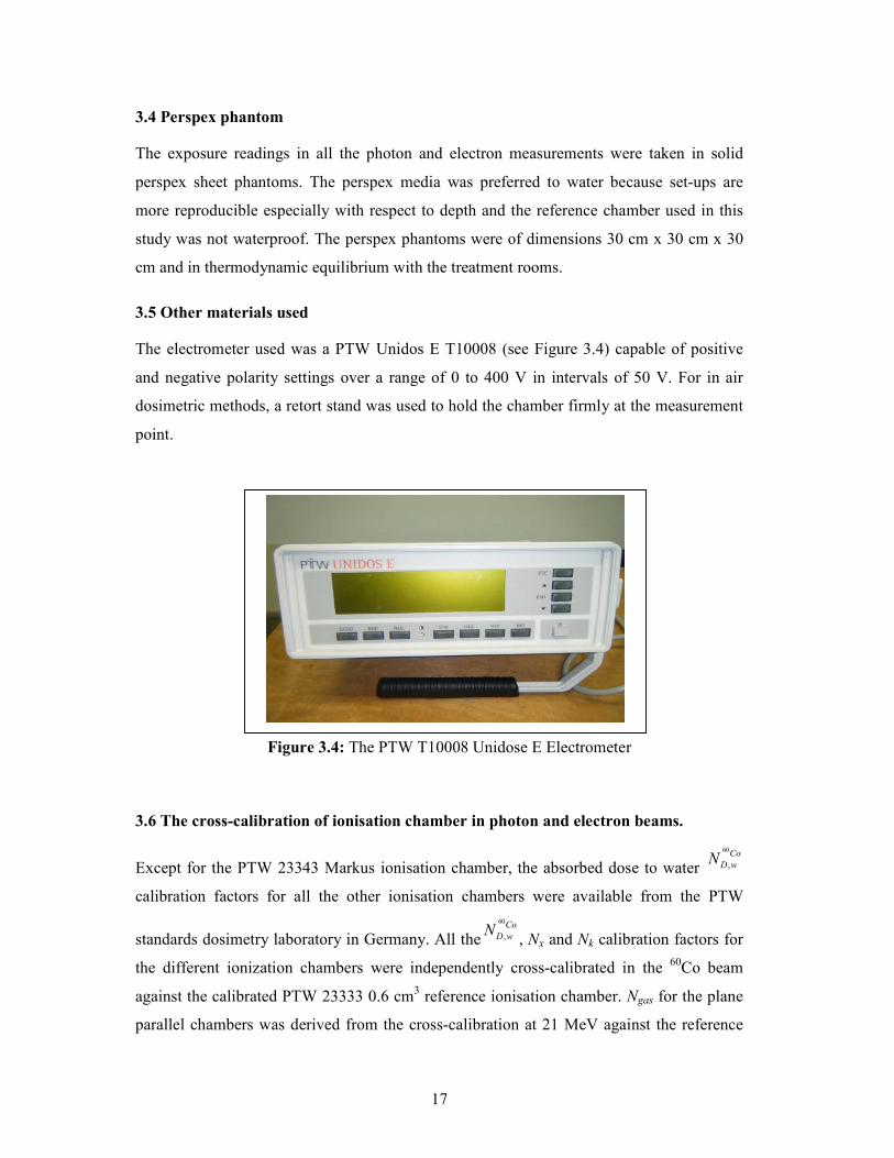
3.5 Other materials used
The electrometer used was a PTW Unidos E T10008 (see Figure 3.4) capable of positive
and negative polarity settings over a range of 0 to 400 V in intervals of 50 V. For in air
dosimetric methods, a retort stand was used to hold the chamber firmly at the measurement
point.
Figure 3.4: The PTW T10008 Unidose E Electrometer
3.6 The cross-calibration of ionisation chamber in photon and electron beams.
Except for the PTW 23343 Markus ionisation chamber, the absorbed dose to water
60
,
Co
D w�
calibration factors for all the other ionisation chambers were available from the PTW
standards dosimetry laboratory in Germany. All the
60
,
Co
D w�, �x and �k calibration factors for
the different ionization chambers were independently cross-calibrated in the 60
Co beam
against the calibrated PTW 23333 0.6 cm3 reference ionisation chamber. �gas for the plane
parallel chambers was derived from the cross-calibration at 21 MeV against the reference
18
ionisation chamber. The recommendations of the AAPM TG-21 and IAEA TRS-398
protocols were followed for the cross-calibration procedures.
3.6.1 Cross-calibration of the
60
,
Co
D w�for ionisation chambers in
60Co beam.
The absorbed dose to water calibration factors for any ionisation chamber Y, under test
against a reference ionisation chamber ref, is given by
60 60
, ,
( )( ) .( )
( )
refCo Co
D w Y D w ref
Y
M� �
M=
………………………………………………….…… (15)
Where (M)ref and (M)Y are the electrometer readings for an ionisation chamber in the 60
Co
beam for the reference and the chamber under test, respectively.
3.6.2 Cross-calibration of the 60
Co exposure calibration factor �x’s.
The 60
Co exposure calibration factor �x for the PTW 23333 0.6 cm3was calculated using
39821
21
( )( )
( )
w IAEATRSx AAPMTG
eq AAPMTG
D�
MfA BSF
−−
−
= …………………………..……….. (16)
Where Dw is as given in equation (1); f is 0.967 cGy/R, the dose to water per roentgen of
exposure; Aeq is 0.989, a factor that accounts for attenuation and scattering in a small mass
of water of 0.5 cm radius at the reference depth; BSF is the 0.5 cm depth tissue air ratio;
and M (nC) is the electrometer reading for 10 cm x 10 cm field size, normalized to 20oC
temperature and a pressure of one standard atmosphere and corrected for timer errors in
accordance with the IAEA TRS-398 formalism i.e.
. . . .raw
TP pol elec s
MM k k k k
t τ=
+ …………………………..……..………...….… (17)
where rawMthe uncorrected reading, τ is is the timer error, kTP is temperature pressure
correction factor, kelec is the electrometer calibration correction factor and ks is the
recombination correction factor.
19
3.6.3 Cross-calibration of the �gas for plane-parallel chambers in electron beams.
The plane-parallel chambers were cross-calibrated against the PTW 23333 0.6 cm3
reference ionisation chamber whose replacement correction (Prep) was 0.994 at 21 MeV, the
highest electron energy available at the department. The AAPM TG-21 formalism was used
i.e.
( )( )
( )
cylin
gas ion replp p
gas p p
ion
M� P P�
MP
−−
=……………………………………………………….…. (18)
where M is the response of the chamber in question at dmax, p-p and cylin refer to the plane-
parallel and cylindrical chambers respectively.
3.7 The absorbed dose measurement in megavoltage photon beams.
The charge readings at a point in the perspex phantom were measured with ionization
chambers with the center of the sensitive volume placed at 4.4 cm depth, the water
equivalent reference depth as used for calibration of the ionisation chambers in the 60
Co
beams i.e. 5 cm of water. The centers of the chambers were aligned with the isocentre of
the treatment machine. The dose was referenced to the PTW 23333 0.6 cm3 ionisation
chamber using its 60
Co absorbed dose to water calibration factor
60
,
Co
D w�. The dose to water at
the reference depth with the chamber removed was calculated using equation (1).
The chambers and the perspex phantom were allowed to equilibrate with the ambient air
temperature. With the PTW 23333 0.6 cm3 reference chamber connected to the
electrometer and the machine in the beam off mode, the leakage at the positive polarity of
the electrometer was -0.023 nC (with medium range settings, 12.0 nA) for 732.0 seconds.
Charge readings were taken for 100 monitor units. The measurements were repeated three
times at each polarity of each ionization chamber. The mean value of the readings was then
calculated. Throughout the study, the absolute value of the polarising voltages was
maintained at either +400V, -400V or +200 V. The readings were corrected for the standard
environmental conditions of temperature and pressure, ion recombination and polarity
effects but the humidity corrections were not considered. The resultant corrected charge
reading and the known absorbed dose rate to the water under reference conditions were
used to derive the calibration factor for each cylindrical ionization chamber ,
Q
D w�. The
measurement of absorbed dose to water requires a beam quality specifier TPR20,10. The

20
beam quality specifier TPR20,10 for the two photon energies (6 MV and 18 MV) was 0.674
and 0.770, respectively.
3.8 The absorbed dose measurement in electron beams.
The charge readings for 100 monitor units in a perspex phantom were measured with the
centre of the sensitive volume of the ionization chambers placed at the depth of maximum
dose, at a constant source to surface distance of 100 cm, in a 10 cm x 10 cm field size. The
chambers and the perspex phantom were allowed to equilibrate with the ambient air
temperature. The chambers were first cross-calibrated for �gas against the cylindrical
reference ionisation chamber at 21 MeV using equation (18).
The measurements were repeated three times at each polarity of the ionization chamber.
The mean value of the readings was then calculated. Throughout the study, the absolute
value of the polarising voltages was maintained at either +400V, -400V or +200 V. The
readings were corrected for the standard environmental conditions of temperature and
pressure, ion recombination and polarity effects. Humidity corrections were not considered.
Equation (2) was used for the determination of absorbed dose to water. Table 3.4 shows the
beam characteristics used for the measurement and calculation process.
Table 3.4: The beam characteristics for the clinical electron beams and the mean restricted
collision mass stopping power of perspex to air used in this study.
Energy
(MeV)
R50
/(cm)
Eo
/(MeV)
dmax
/(cm)
Rp
/ cm
Edmax perspex
air
Lρ
−
5 2.05 4.77 1.17 2.5 2.60 1.038
6 2.40 5.58 1.38 3.0 3.04 1.028
7 2.75 6.41 1.59 3.5 3.50 1.020
9 3.51 8.18 2.03 4.5 4.46 1.006
12 4.68 10.90 2.66 6.0 6.15 0.988
14 5.28 12.31 2.89 7.0 7.31 0.977
15 5.93 13.83 2.64 7.5 9.77 0.968
18 7.30 17.01 2.03 9.0 13.91 0.947
21 8.23 19.19 1.40 11.5 18.51 0.939
R50 is extracted from the commissioning data at Charlotte Maxeke Johannesburg Academic Hospital for the
Siemens Primus linear accelerators.

21
3.9 Determination of beam quality correction factors
The photon beam quality correction factors were determined according to equation (1) in
which the dose measured by PTW 23333 ionisation chamber was used as the reference
dose. The corrected average measured charge readings and the absorbed dose to water
calibration factor from the cross-calibration process in the 60
Co were used for calculation
i.e.
( )( )
60
,
..........................................................................................................(19)( )
Q
w ref
Q Q CoY
Y D w Y
Dk
M �=
Where Q denotes the quality of the beam in which the chambers ref and Y were used for
beam quality correction measurements.
The electron beam quality correction factors (kq,E) were determined as the ratio of the
absorbed dose to water calibration factors in the electron beam and the reference 60
Co beam
for that particular chamber Y (Hubert, Hugo & Wim, 1999, Achim & Ralf-Peter, 2007,
González-Castaño et.al.,2009).
60
,
,
,
,
( ).......................................................................................................................(20)
( )
q E
D w Y
q E Co
D w Y
�k
�=
The absorbed dose to water calibration factors in the electron beam ,
,( )q E
D w Y� is determined
as the ratio of the absorbed dose to water measured by the PTW 23333 reference ionisation
chamber to the absorbed dose to water measured by the chamber Y under test.
)(( ))(( )
,
max,
, ,
max
( ) ...........................................................................................(21)
q E
waterrefq E
D w Y q E
waterY
D at d�
D at d=
where
60
,( )Co
D w Y� in equation (20) is obtained from the result of the cross-calibration in
equation (15).
22
CHAPTER FOUR: RESULTS AD DISCUSSIOS
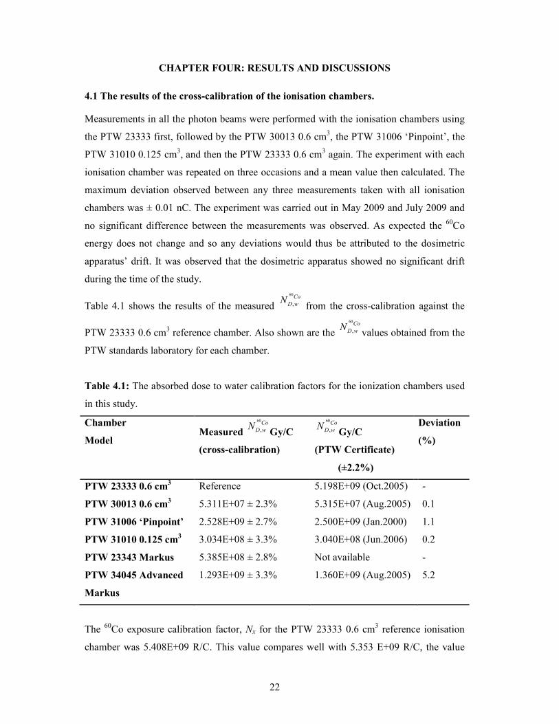
4.1 The results of the cross-calibration of the ionisation chambers.
Measurements in all the photon beams were performed with the ionisation chambers using
the PTW 23333 first, followed by the PTW 30013 0.6 cm3, the PTW 31006 ‘Pinpoint’, the
PTW 31010 0.125 cm3, and then the PTW 23333 0.6 cm
3 again. The experiment with each
ionisation chamber was repeated on three occasions and a mean value then calculated. The
maximum deviation observed between any three measurements taken with all ionisation
chambers was ± 0.01 nC. The experiment was carried out in May 2009 and July 2009 and
no significant difference between the measurements was observed. As expected the 60
Co
energy does not change and so any deviations would thus be attributed to the dosimetric
apparatus’ drift. It was observed that the dosimetric apparatus showed no significant drift
during the time of the study.
Table 4.1 shows the results of the measured
60
,
Co
D w� from the cross-calibration against the
PTW 23333 0.6 cm3 reference chamber. Also shown are the
60
,
Co
D w�values obtained from the
PTW standards laboratory for each chamber.
Table 4.1: The absorbed dose to water calibration factors for the ionization chambers used
in this study.
Chamber
Model Measured
60
,
Co
D w�Gy/C
(cross-calibration)
60
,
Co
D w�Gy/C
(PTW Certificate)
(±2.2%)
Deviation
(%)
PTW 23333 0.6 cm3 Reference 5.198E+09 (Oct.2005) -
PTW 30013 0.6 cm3 5.311E+07 ± 2.3% 5.315E+07 (Aug.2005) 0.1
PTW 31006 ‘Pinpoint’ 2.528E+09 ± 2.7% 2.500E+09 (Jan.2000) 1.1
PTW 31010 0.125 cm3 3.034E+08 ± 3.3% 3.040E+08 (Jun.2006) 0.2
PTW 23343 Markus 5.385E+08 ± 2.8% Not available -
PTW 34045 Advanced
Markus
1.293E+09 ± 3.3% 1.360E+09 (Aug.2005) 5.2
The 60
Co exposure calibration factor, �x for the PTW 23333 0.6 cm3 reference ionisation
chamber was 5.408E+09 R/C. This value compares well with 5.353 E+09 R/C, the value
23
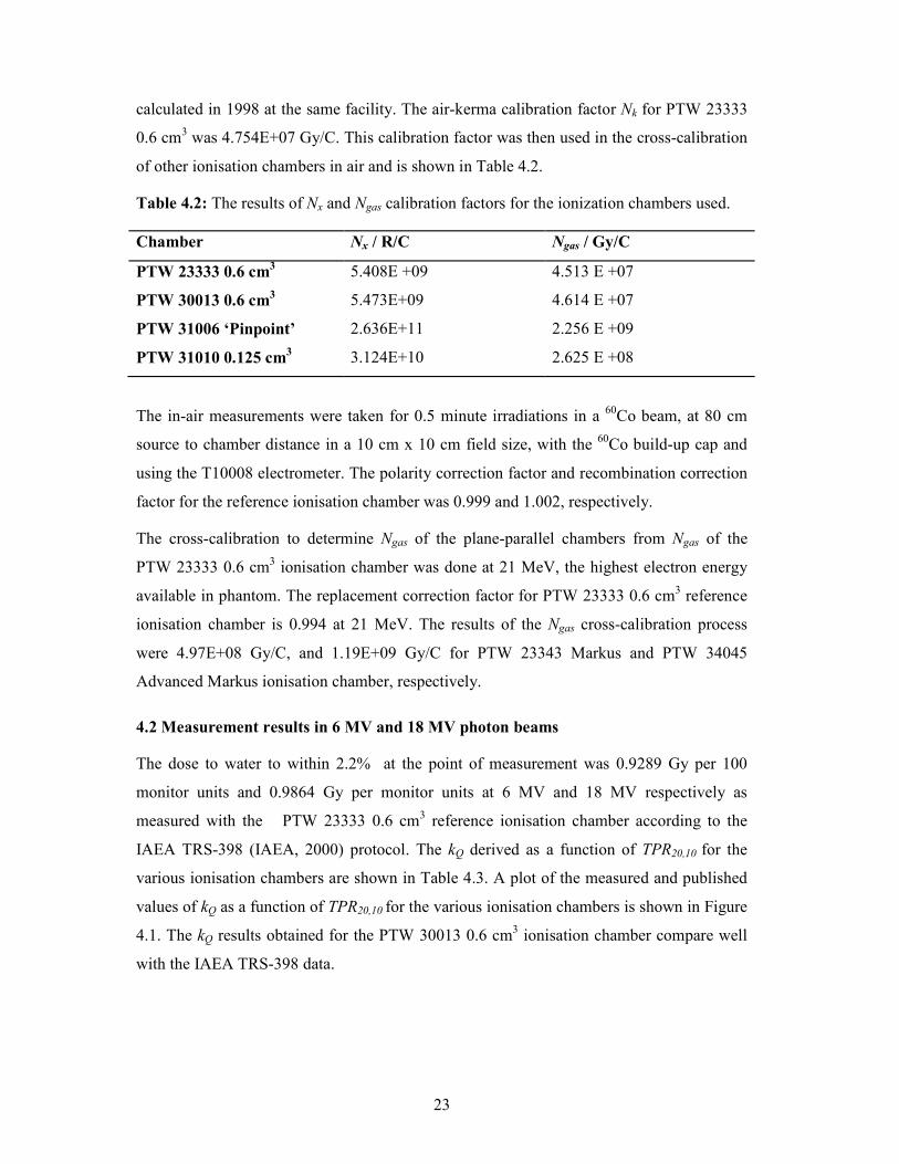
calculated in 1998 at the same facility. The air-kerma calibration factor �k for PTW 23333
0.6 cm3 was 4.754E+07 Gy/C. This calibration factor was then used in the cross-calibration
of other ionisation chambers in air and is shown in Table 4.2.
Table 4.2: The results of �x and �gas calibration factors for the ionization chambers used.
Chamber �x / R/C �gas / Gy/C
PTW 23333 0.6 cm3 5.408E +09 4.513 E +07
PTW 30013 0.6 cm3 5.473E+09 4.614 E +07
PTW 31006 ‘Pinpoint’ 2.636E+11 2.256 E +09
PTW 31010 0.125 cm3 3.124E+10 2.625 E +08
The in-air measurements were taken for 0.5 minute irradiations in a 60
Co beam, at 80 cm
source to chamber distance in a 10 cm x 10 cm field size, with the 60
Co build-up cap and
using the T10008 electrometer. The polarity correction factor and recombination correction
factor for the reference ionisation chamber was 0.999 and 1.002, respectively.
The cross-calibration to determine �gas of the plane-parallel chambers from �gas of the
PTW 23333 0.6 cm3 ionisation chamber was done at 21 MeV, the highest electron energy
available in phantom. The replacement correction factor for PTW 23333 0.6 cm3 reference
ionisation chamber is 0.994 at 21 MeV. The results of the �gas cross-calibration process
were 4.97E+08 Gy/C, and 1.19E+09 Gy/C for PTW 23343 Markus and PTW 34045
Advanced Markus ionisation chamber, respectively.
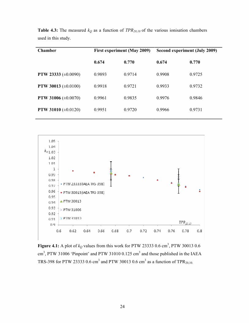
4.2 Measurement results in 6 MV and 18 MV photon beams
The dose to water to within 2.2% at the point of measurement was 0.9289 Gy per 100
monitor units and 0.9864 Gy per monitor units at 6 MV and 18 MV respectively as
measured with the PTW 23333 0.6 cm3 reference ionisation chamber according to the
IAEA TRS-398 (IAEA, 2000) protocol. The kQ derived as a function of TPR20,10 for the
various ionisation chambers are shown in Table 4.3. A plot of the measured and published
values of kQ as a function of TPR20,10 for the various ionisation chambers is shown in Figure
4.1. The kQ results obtained for the PTW 30013 0.6 cm3 ionisation chamber compare well
with the IAEA TRS-398 data.
24
Table 4.3: The measured kQ as a function of TPR20,10 of the various ionisation chambers
used in this study.
Chamber First experiment (May 2009) Second experiment (July 2009)
0.674 0.770 0.674 0.770
PTW 23333 (±0.0090) 0.9893 0.9714 0.9908 0.9725
PTW 30013 (±0.0100) 0.9918 0.9721 0.9933 0.9732
PTW 31006 (±0.0070) 0.9961 0.9835 0.9976 0.9846
PTW 31010 (±0.0120) 0.9951 0.9720 0.9966 0.9731
Figure 4.1: A plot of kQ values from this work for PTW 23333 0.6 cm3, PTW 30013 0.6
cm3, PTW 31006 ‘Pinpoint’ and PTW 31010 0.125 cm
3 and those published in the IAEA
TRS-398 for PTW 23333 0.6 cm3 and PTW 30013 0.6 cm
3 as a function of TPR20,10.

25
4.3 Measurement results in the electron beam qualities.
For the electron beams, the doses were measured with the reference point of each of the
chambers at the reference depth in a perspex phantom using a 10 cm x 10 cm applicator and
an SSD of 100 cm. The measured electron doses are as summarized in Table 4.4.
Table 4.4. Summary of the doses in Gy per 100 monitor units at dmax using each of the
ionization chambers.
ominal
Energy
(MeV)
R50/
cm
PTW
23333
0.6 cm3
PTW
30013
0.6 cm3
PTW
31006
Pinpoint
PTW
31010
0.125 cm3
PTW
23343
Markus
PTW
34045
Advanced
Markus
5 2.05 0.980 0.970 0.999 0.996 1.030 0.985
6 2.40 0.983 0.976 1.005 0.996 1.030 0.983
7 2.75 0.971 0.965 0.988 0.981 1.010 0.963
9 3.51 0.973 0.968 0.996 0.980 1.010 0.971
12 4.68 0.965 0.965 0.987 0.958 0.996 0.962
14 5.28 0.954 0.952 0.977 0.945 0.981 0.949
15 5.93 0.955 0.954 0.973 0.948 0.962 0.950
18 7.30 0.934 0.931 0.944 0.928 0.936 0.932
21 8.23 0.975 0.971 0.992 0.970 0.981 0.974
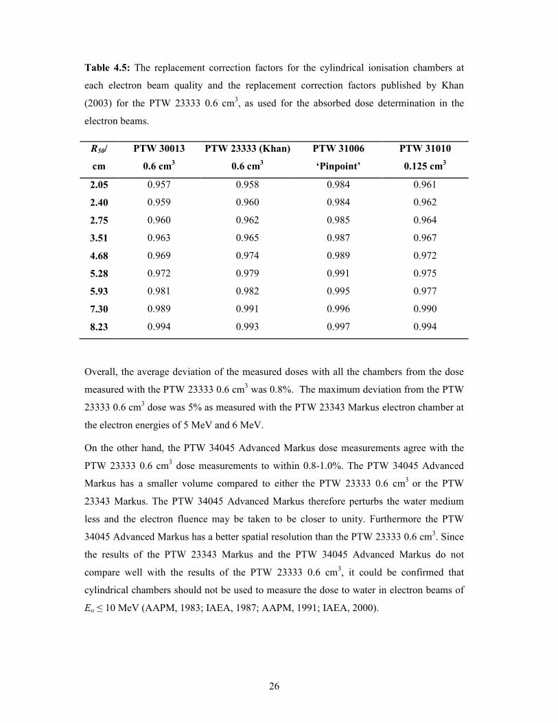
The unrestricted stopping power ratio of water to air is 1.033 and the replacement
correction factors used for the determination of dose for the various ionisation chambers are
shown in Table 4.5. The values of the replacement correction factors for the PTW 23333
0.6 cm3 and PTW 30013 0.6 cm
3 as reported by Khan (2003) are also included.
26
Table 4.5: The replacement correction factors for the cylindrical ionisation chambers at
each electron beam quality and the replacement correction factors published by Khan
(2003) for the PTW 23333 0.6 cm3, as used for the absorbed dose determination in the
electron beams.
R50/
cm
PTW 30013
0.6 cm3
PTW 23333 (Khan)
0.6 cm3
PTW 31006
‘Pinpoint’
PTW 31010
0.125 cm3
2.05 0.957 0.958 0.984 0.961
2.40 0.959 0.960 0.984 0.962
2.75 0.960 0.962 0.985 0.964
3.51 0.963 0.965 0.987 0.967
4.68 0.969 0.974 0.989 0.972
5.28 0.972 0.979 0.991 0.975
5.93 0.981 0.982 0.995 0.977
7.30 0.989 0.991 0.996 0.990
8.23 0.994 0.993 0.997 0.994
Overall, the average deviation of the measured doses with all the chambers from the dose
measured with the PTW 23333 0.6 cm3 was 0.8%. The maximum deviation from the PTW
23333 0.6 cm3 dose was 5% as measured with the PTW 23343 Markus electron chamber at
the electron energies of 5 MeV and 6 MeV.
On the other hand, the PTW 34045 Advanced Markus dose measurements agree with the
PTW 23333 0.6 cm3 dose measurements to within 0.8-1.0%. The PTW 34045 Advanced
Markus has a smaller volume compared to either the PTW 23333 0.6 cm3
or the PTW
23343 Markus. The PTW 34045 Advanced Markus therefore perturbs the water medium
less and the electron fluence may be taken to be closer to unity. Furthermore the PTW
34045 Advanced Markus has a better spatial resolution than the PTW 23333 0.6 cm3. Since
the results of the PTW 23343 Markus and the PTW 34045 Advanced Markus do not
compare well with the results of the PTW 23333 0.6 cm3, it could be confirmed that
cylindrical chambers should not be used to measure the dose to water in electron beams of
Eo ≤ 10 MeV (AAPM, 1983; IAEA, 1987; AAPM, 1991; IAEA, 2000).

27
The measured doses were used to derive the absorbed dose to water calibration factors for
the electron beams. These absorbed dose to water calibration factors ,
,
q E
D w� (shown in Table
4.6) were in turn used to determine the kq,E for each of the ionisation chambers at each
electron energy. The kq,E obtained as a function of R50 for the cylindrical chambers and for
the parallel plate chambers are shown in Table 4.7 and Figure 4.2. It can be noted that the
kq,E value for PTW 31006 ‘Pinpoint’ whose replacement correction factor is small, is very
close to unity.
Table 4.6: The calculated ,
,
q E
D w� x 10
7 Gy/C at each electron energy for the various
ionisation chambers.
R50
/ cm
PTW 23333
0.6 cm3
PTW 30013
0.6 cm3
PTW 31006
Pinpoint
PTW 31010
0.125 cm3
PTW 23343
Markus
PTW 34045
Advanced Markus
2.05 4.63 4.78 233 26.6 49.4 123
2.40 4.60 4.73 231 26.5 49.3 122
2.75 4.56 4.70 230 26.4 49.4 122
3.51 4.52 4.64 226 26.2 48.5 120
4.68 4.46 4.56 223 26.2 48.0 118
5.28 4.43 4.54 220 26.1 47.7 117
5.93 4.43 4.53 220 25.8 48.1 116
7.30 4.46 4.58 222 26.1 48.4 115
8.23 4.26 4.37 210 24.9 45.8 110
28
Table 4.7: The results of the kq,E values determined as a function of R50 for the various
ionisation chambers.
R50
(cm)
PTW 23333
±0.007
PTW 30013
±0.008
PTW 31006
±0.010
PTW 31010
±0.005
PTW 23343
±0.011
PTW 34045
±0.007
2.05 0.891 0.900 1.036 0.877 0.917 0.951
2.40 0.884 0.891 1.024 0.873 0.916 0.946
2.75 0.878 0.884 1.022 0.870 0.918 0.947
3.51 0.869 0.873 1.003 0.862 0.901 0.927
4.68 0.859 0.859 0.989 0.865 0.892 0.913
5.28 0.852 0.854 0.978 0.860 0.885 0.905
5.93 0.852 0.853 0.978 0.851 0.894 0.895
7.30 0.859 0.862 0.987 0.862 0.899 0.893
8.23 0.820 0.824 0.932 0.822 0.850 0.847
Figure 4.2: A plot of kq,E as a function of R50 for the plane-parallel and the cylindrical
ionisation chambers.

29
CHAPTER FIVE: COCLUSIOS AD RECOMMEDATIOS
Cross-calibrations of
60
,D w
Co� and x�
for the PTW 30013 0.6 cm3 ionisation chamber, the
PTW 31006 ‘Pinpoint’ ionisation chamber, the PTW 31010 0.125 cm3 ionisation chamber,
the PTW 23343 Markus and the PTW 34045 Advanced Markus ionisation chamber against
the PTW 23333 0.6 cm3 reference ionisation chamber were performed. The cross-
calibration factors compare well with those on their respective chamber certificates. These
cross-calibration factors have been obtained using the existing international dosimetry
protocols, they are therefore traceable to standard dosimetry laboratories and they can be
applied in the routine and periodical quality assurance programmes of Charlotte Maxeke
Johannesburg Academic Hospital radiation clinics, with confidence.
The beam quality correction factors for the PTW 30013 0.6 cm3 ionisation chamber in
photon beams with TPR20,10 of 0.674 and 0.770 were determined with an accuracy of
0.2%, compared to the IAEA TRS-398 published values.
The beam quality correction factors for the PTW 23343 Markus ionisation chamber in a
range of electron beam qualities of R50 of 2.05 cm to 8.23 cm (4.77 MeV≤ Eo ≤19.19 MeV)
were determined with an accuracy of 1.2%, compared to the IAEA TRS-398 published
values. Since the uncertainties are systematically low and not significant, this study
establishes that any of the ionization chamber types used in this study could be used as
reference chambers for clinical dosimetry. Although different centers may have different
beam designs and measuring methods, the kQ values for the chambers used in this study can
be applied to other beams of the same beam quality.
The overall deviation of 5% in the results of the PTW 23343 Markus and the PTW 34045
Advanced Markus from the results of the PTW 23333 0.6 cm3 confirms that cylindrical
chambers should not be used to measure the dose to water in electron beams of Eo ≤ 9
MeV. Cylindrical chambers, however, can be used for less precise daily quality control
checks of electron beams of Eo ≤ 9 MeV where compliance to a range of dose or dose rates
only is to be confirmed.
The beam quality correction factors kQ and kq,E for the PTW 31010 0.125 cm3, 31006
‘Pinpoint’ and 34045 Advanced Markus models of ionisation chambers for which no
published data exist, were determined with reasonable accuracy. The electron beam quality
correction factors were determined at a dose-rate of 300 MU/ min. They could also be

30
tested at higher-energy electron dose rates, i.e. 900 MU/min for the Siemens PRIMUSTM
LINACS.
This work is one of the few studies which demonstrates clearly the ability to determine
beam quality correction factors in a clinical setting. Cross-calibrations were performed of
the absorbed dose to water calibration factors of the Markus, the ‘PinPoint’ and the
Advanced Markus ionisation chambers (M’ule, 2008). The kq,E values determined for the
Advanced Markus ionisation chamber will provide improved accuracy in dosimetry with
this chamber since the error previously introduced by using published or extrapolated kq,E
values for the Markus ionisation chamber is now eliminated. The ‘PinPoint’ ionisation
chamber can also be used for absolute dosimetry since the beam quality correction factors
are now determined for the beam qualities available at the Charlotte Maxeke Johannesburg
Academic Hospital.
Although the results of this study are clinically accurate, a Monte Carlo Simulation Code
could be resourced to test the validity of their statistical uncertainties.

31
REFERECES
AAPM. (1983). A Protocol for the Determination of Absorbed Dose from High-Energy
Photon and Electron beams. Med. Phys., 10, 741-771.
AAPM. (1991). Clinical Electron-Beam Dosimetry. Med. Phys., 18(1), 73 - 109.
Achim, K. & Ralf-Peter, K. (2007). Calorimetric determination of factors for NE 2561
and NE 2571 ionisation chambers in 5 cm x 5 cm and 10 cm x 10 cm radiotherapy beams
of 8 MV and 16 MV photons. Phys. Med. Biol., 52, 6243-6259.
Almond, P. R., Biggs, P. J., Coursey, B. M., Hanson, W. F., Huq, M. S., Nath, R., &
Rogers, D. W. O. (1999). AAPM’s TG-51 protocol for clinical reference dosimetry of high-
energy photon and electron beams. Med. Phys., 26, 1847-1870.
Andreo, P. (1992). Absorbed dose Beam Quality Factors for the Dosimetry of High-Energy
Photon Beams. Phy. Med. Biol., 37, 2189-2211.
Andreo, P. & Saiful, H.M. (2001). Reference dosimetry in clinical high-energy photon
beams: Comparison of the AAPMTG-51 and AAPM TG-21 dosimetry protocols. Am.
Assoc. Phys. Med., 1, 46-54.
Andreo, P. & Saiful, H.M. (2004). Advances in the Determination of Absorbed dose to
water in Clinical High-energy Photon and Electron Beams using Ionisation Chambers.
Phys. Med. Biol., 49, R50-R104.
ARPANSA. (2001). Fact Sheet: The use of 60
Co Calibration Factors in Megavoltage
Radiotherapy dosimetry. Yallambie Australia: Commonwealth of Australia.
Chantal, M., Hubert, T., Hugo, P., Jo, D. J., Laila, N., Marie-Therese, H., Marleen, P.,
Sofie, G., Stefaan, V. & Van der Plaetsen, A. (2002). Absorbed dose to water based
dosimetry versus air kerma based dosimetry for high-energy photon beams: an
experimental study. Phys. Med. Biol., 47, 421-440.
Christ, G., Dohm, O.S., Bruggmoser, G & Schule, E. (2002). The use of plane-parallel
chambers in electron dosimetry without any calibration. Phys. Med.Biol. 47, N121-N126.
32
Coffey, C.W., DeWerd, L.A., Liu, C., Ma, C-M., Nath, R., Seltzer, S.M., & Seuntjens, J.P.
(2001). AAPM protocol for 40-300 kV x-ray beam dosimetry in radiotherapy and
radiobiology. Med. Phys., 28 (6), 868-893.
Dusantoy, A. R., McEwen, M. R., & Williams, A. J. (1998). The calibration of Therapy
Level Electron Beams Ionisation Chambers in terms of Absorbed dose to water. Phys. Med.
Biol., 43, 2503-2519.
European Medical Radiation Learning Development. (2001). Physics of Nuclear Medicine
Workbook. Kings College London-GKT School of Medicine.
Hatica, B., Aydin, C., Murat, O. & Hilal, A. (2009). Surface dose measurements with
GafChromic EBT film for 6 and 18 MV photon beams.Phys. Med. 25(2), 101-104.
Hubert, T., Hugo, P., & Wim, M. (1999). Absorbed dose beam quality correction factors kQ
for the NE2571 chamber in a 5 MV and a 10 MV photon beam. Phys. Med. Biol., 44, 647-
663.
IAEA. (1987). Absorbed dose Determination in Photon and Electron Beams: An
International Code of Practice based on Standards of Absorbed Dose to Water; Technical
Report Series Number 277. Vienna: IAEA.
IAEA. (2000). Absorbed Dose Determination in External Beam Radiotherapy: Technical
Report Series Number 398. An International Code of Practice. Vienna: IAEA.
Khan, F. M. (2003). The physics of radiation therapy. Philadelphia USA: Lippincott
Williams & Wilkins.
Kubo, H., Kent, l.J., & Krithivas, G. (1986). Determination of Ngas and Prep factors from
commercially available parallel plate chambers: AAPM Task Group 21 protocol. Med.
Phys., 13 (6), 908-912.
Ma, C-M. & Nahum, A. E. (1995). Calculations of ion chamber displacement effect
corrections for medium-energy x-ray dosimetry. Phys. Med. Biol., 40, 45-62.
Mijnheer, B.J. & Wittkamper, F.W. (1986). Comparison of recent codes of practice for
high-energy photon dosimetry. Phys. Med. Biol. 31(4), 407-416.
33
M’ule, C. B. (2008). Small Field Dosimetry of High-Energy Electron Beams. A research
report submitted to the Faculty of Science, University of the Witwatersrand, Johannesburg,
in partial fulfillment of the requirements for the degree of Master of Science.
Nitschke, K.N., (1998). Absorbed Dose Determination in Photon and Electron Beams. An
adaptation of the IAEA International Codes of Practice. New Zealand: Australasian
College of Physical Scientists & Engineers in Medicine.
Physikalisch-Technische Werkstätten. (2005). User manual chamber specifications.
Freiburg: PTW-Freiburg publication.
Podgorsak, E. B. (2005). Radiation Oncology Physics: Calibration of Photon and Electron
Beams. Vienna: IAEA.
Rogers, D. W. O. (1990). New Dosimetry Standards: Advances in radiation oncology
physics, AAPM Monograph Series. Lawrence Kansas: AAPM Summer School.
Rogers, D. W. O. (1992). The advantages of Absorbed dose Calibration Factors Med.
Phys., 19, 1227-1239.
Rogers, D. W. O. (1996). Fundamentals of Dosimetry Based on Absorbed Dose Standards.
Teletherapy Physics, Present and the Future. Vancouver, BC: AAPM summer school. 319-
356.
Saiful, H.M. (2001). Comparison of the IAEA TRS-398 and AAPM TG-51 Absorbed dose
to water Protocols in the Dosimetry of High-Energy Photon and Electron beams. Phys.
Med. Bio., 46, 2985-3006.