Experimental Demonstration of Direct Terahertz Detection - Gredos

Brigham Young University Brigham Young University
BYU ScholarsArchive BYU ScholarsArchive
Faculty Publications
2020-9
Experimental Demonstration of Heat Loss and Turn-Down Ratio Experimental Demonstration of Heat Loss and Turn-Down Ratio
for a Multi-Panel, Actively Deployed Radiator for a Multi-Panel, Actively Deployed Radiator
Rydge B. Mulford University of Dayton
Samuel D. Salt Brigham Young University - Provo
Lance P. Hyatt Brigham Young University - Provo
Kyle S. Meaker Brigham Young University - Provo
Vivek H. Dwivedi NASA Goddard Space Flight Center
See next page for additional authors
Follow this and additional works at: https://scholarsarchive.byu.edu/facpub
Part of the Mechanical Engineering Commons
BYU ScholarsArchive Citation BYU ScholarsArchive Citation Mulford, Rydge B.; Salt, Samuel D.; Hyatt, Lance P.; Meaker, Kyle S.; Dwivedi, Vivek H.; Jones, Matthew R.; and Iverson, Brian D., "Experimental Demonstration of Heat Loss and Turn-Down Ratio for a Multi-Panel, Actively Deployed Radiator" (2020). Faculty Publications. 5087. https://scholarsarchive.byu.edu/facpub/5087
This Peer-Reviewed Article is brought to you for free and open access by BYU ScholarsArchive. It has been accepted for inclusion in Faculty Publications by an authorized administrator of BYU ScholarsArchive. For more information, please contact [email protected], [email protected].

Authors Authors Rydge B. Mulford, Samuel D. Salt, Lance P. Hyatt, Kyle S. Meaker, Vivek H. Dwivedi, Matthew R. Jones, and Brian D. Iverson
This peer-reviewed article is available at BYU ScholarsArchive: https://scholarsarchive.byu.edu/facpub/5087

1
Experimental Demonstration of Heat Loss and Turn-Down Ratio for a Multi-Panel, Actively Deployed Radiator
Rydge B. Mulford,a Samuel D. Salt,b Lance P. Hyatt,b Kyle S. Meaker,b
Vivek H. Dwivedi,c Matthew R. Jonesb and Brian D. Iversonb,1
aUniversity of Dayton, Dayton, OH, 45410, USA bBrigham Young University, Provo, UT, 84602, USA
cNASA Goddard Space Flight Center, Greenbelt, MD, 20771, USA
Abstract
Origami-inspired, dynamic spacecraft radiators have been proposed which utilize an expandable/collapsible surface
capable of large variations in emitting surface area. In this work, an experimental prototype of this concept is realized
and its performance is analyzed. In particular, we demonstrate the capability of maintaining a spacecraft component
at a desired operating temperature through the expansion and contraction of a collapsible radiator to control radiative
heat loss. Four aluminum panels are connected via a flexible hinge constructed from interwoven copper wires and
suspended from an actuating framework. The radiator panels are connected to a heated aluminum block. The radiator
is placed in a vacuum environment with cooled surroundings (173 K) and the total radiative cooling power is
determined as a function of radiator actuation position for a constant aluminum block temperature. As the radiator
actuates from extended to collapsed, the heat transfer decreases and the fin efficiency increases. For a limited actuation
range, the four-panel radiator exhibits a turn-down ratio (largest cooling power / smallest cooling power) of 1.31. A
numerical model validated in this work predicts a turn-down ratio of 2.27 for actuation over the full range of radiator
positions in surroundings at 4 K. Future revisions that exhibit an increase in panel and hinge thermal conductivities
and utilizing eight panels would yield a turn-down ratio of 6.01. Assuming infinite thermal conductivity and infinite
hinge conductance, the turn-down ratios for two, four and eight panel radiators, respectively, are 2.00, 3.98, and 7.92.
1Corresponding author: [email protected] (B. D. Iverson)

2
Nomenclature
e = emissivity
k = hinge conductance (W K-1)
f = radiator angle
s = Stefan-Boltzmann constant (5.67 x 10⁻⁸ W m-1 K-4)
A = surface area (m2)
L = length (m)
P = heater power (W)
T = temperature (K)
k = thermal conductivity (W m-1 K-1)
qrad = radiative cooling power (W)
r = radius (m)
t = thickness (m)
w = width (m)
x = horizontal position on fully-extended radiator, measured from center of aluminum block (cm)
Subscripts
1 - 4 = panel number
b = aluminum block
h = flexible hinge
m = multi-layer insulation (MLI)
p = radiator panel
s = standoffs
surr = surroundings

3
1 Introduction
Radiative cooling of spacecraft is commonly achieved through the use of specialized radiating surfaces. Currently,
spacecraft radiators are sized sufficiently large so as to emit the maximum cooling load expected to occur in the
spacecraft’s lifetime [1]. However, spacecraft waste heat loads can be highly variable, increasing or decreasing
significantly with orbit position, on-board electronic waste heat generation, and distance from the sun for
interplanetary missions. Due to the static nature of radiator geometry and radiative surface properties, a decrease in
the radiator’s cooling load results in a decrease in the overall spacecraft temperature, causing the temperature of critical
components to fall below established limits. To mitigate this effect, survival resistance heaters are placed throughout
the spacecraft and activated when component temperatures approach an established threshold [1]. Although effective,
use of survival heaters requires the installation of additional battery and solar panel capacity, decreasing allowable
payload weight and power capacity for scientific instruments or communication arrays. The disadvantages of survival
heaters are especially evident for small, high-powered spacecraft or interplanetary missions, where large variations in
cooling loads and lower thermal mass dramatically increases the spacecraft power and weight used to maintain
temperature set points.
Spacecraft radiators capable of dynamic variation in emitted power offer the potential to reduce the amount of
survival heating necessary to maintain spacecraft temperatures within established limits [2]. Several technologies exist
or have been proposed in the literature that allow for dynamic control of spacecraft radiator heat transfer. The turn-
down ratio, or the fraction of largest possible emitted energy to smallest possible emitted energy, provides a metric by
which the effectiveness of these technologies might be compared. Thermochromic surfaces [3–7] or electrochromic
surfaces [8–11] exhibit control of radiative surface properties through variations in surface chemistry via a change in
temperature or voltage, respectively. Recently proposed thermochromic films have exhibited turn-down ratios as high
as 7 [7]. When circulating fluids are used to transfer heat to a radiator, the heat rejection from the radiator may be
controlled by varying the speed, quantity or pathway of the fluid. Examples of this approach include variable
conductance heat pipes [12,13], the International Space Station (ISS) thermal control system [14], or stagnation
radiators [15], with turn-down ratios on the order of 10 or less. However, these methods are not available for small
spacecraft which often do not use circulating fluid loops. Finally, variations to radiator geometry to achieve a change
in radiator heat loss have been proposed or demonstrated, achieving turn-down ratios of 5 or less [16–19]. These
technologies increase or decrease the emitting surface area of a radiator by deploying a radiator panel through

4
expansion of an internal gas [17,20] or through the use of actuation mechanisms driven by a variation in temperature
such as shape-memory alloys [16,18].
Nearly all completed studies on dynamic radiator technologies described in this review use passive solutions to
achieve variation in radiator cooling power. The use of actively manipulated technologies, specifically motorized
surfaces, for spacecraft thermal control has not yet been explored. Likewise, the study of re-deployable radiators has
so far been restricted to the actuation of single-panel radiators acting in parallel. This work considers multiple panels
acting in series. Finally, published works that utilize variable geometry to control radiator cooling power use geometry
as a means of concealing or revealing a black surface, causing the actuating geometry to function mainly as a gate or
shutter as opposed to a means by which large variations in emitting surface area might be realized.
A recently proposed re-deployable radiator design [21–23] utilizes origami topographies to achieve dynamic
control of radiative heat transfer, consisting of several flat, rigid panels connected in a tessellated pattern with the
ability to fold or unfold. As the device unfolds, the emitting surface area of the radiator panels increases causing the
heat transfer to also increase [23]. Conversely, as the device folds, the emitting surface area decreases with an
associated change in the heat transfer. The folding nature of the panels is such that many panels may be included in
the device, significantly increasing the potential variation in radiator surface area. Likewise, individual panels of a
collapsing origami tessellation form cavities with their neighbors, and the aspect ratio of these cavities varies with
actuation. The apparent radiative properties of the cavities formed between neighboring panels are directly related to
the aspect ratio of the cavity [24,25] in a phenomenon known as the cavity effect. As such, origami-inspired radiators
are capable of controlling both surface area and apparent radiative surface properties as a function of position.
However, published research concerning this new technology has focused on the development of models that describe
the radiator’s apparent radiative properties or net radiative heat transfer. An experimental demonstration of the
technology using geometries, surface properties, and structures more appropriate for spacecraft applications has not
yet been completed.
The objective of this work is to develop and test an experimental prototype of an origami-inspired radiator for
three purposes: (1) explore the utility of multiple interconnected, deployable radiator panels, (2) demonstrate the utility
of active control of dynamic radiator panels, (3) validate use of an existing numerical model [26] in order to explore
the radiator design space. The design of the radiator is described first, followed by the experimental methodology used
to measure performance metrics and demonstrate the thermal control potential of this multi-panel, actively-

5
manipulated device. The basic outline of the thermal model used to predict the heat transfer from the radiator is then
presented, with additional details available from [26]. The experimental method used to validate the thermal model is
also presented. Results from the experiment and numerical model are then used to quantify the turn-down ratio and
cooling power of the device. The numerical model is then used to predict the turn-down ratio of deployable radiators
with improved materials and technologies. Finally, results are discussed as they apply to the viability of the approach
for spacecraft thermal control applications and future development considerations.
2 Methodology
2.1 Radiator Design
Previous studies demonstrating the behavior of origami radiators have used thin metal shim stocks (thickness <
0.03 mm) folded into an accordion pattern. However, for spacecraft applications, deployable radiator structures must
utilize rigid panels with structural support. ISS radiators [27], pictured in a semi-extended state in Figure 1, provide
an excellent example of a deployable radiator with space heritage; although, the ISS radiators do not actuate
dynamically and heat is transferred to the radiator panels through a pumped fluid loop. The deployable radiator
discussed in this work was inspired by the ISS radiator design with accommodations for active control and thermal
transport via heat conduction.
Figure 1 – A portion of the External Active Thermal Control System on the International Space Station (ISS) [27]. One of the single-deployment radiators utilized in the thermal control system, a series of connected panels arranged in series, is displayed in the image. Unlike the radiator described in this work, heat is carried to the ISS radiators through a pumped fluid loop in this image.

6
Figure 2 – (a) The panel subsystem, consisting of four solid aluminum panels (labeled 1-4) coated in a spectrally-selective paint typical of spacecraft radiators. The panels are connected with woven copper straps. The left-most panel is connected to a solid aluminum block with embedded heaters. The inset image at the bottom right is a cross-section of the thermal hinge connecting the panels. (b) The actuation subsystem, consisting of two scissor extension mechanisms constructed from aluminum struts, are connected via steel rods with fiberglass sleeves. The entire system actuates up or down with a stepper motor. (c) The combination of the panel and actuation subsystems, forming the complete radiator.
(a)
(b) (c)

7
The radiator developed in this work can be divided into two subsystems; the panel subsystem and the actuation
subsystem. The panel subsystem, pictured in Figure 2a and consisting of four panels and a heated aluminum block all
connected with thermally conductive flexible hinges, is responsible for conducting heat away from the heat source
and radiating this energy to space through thermal emission. The actuation subsystem, pictured in Figure 2b, provides
structure for the panel subsystem and is the mechanism by which the position of the panel subsystem is varied
dynamically. When combined (Figure 2c), the two subsystems create a radiative fin that can be actuated in real time
over a wide range of positions, from nearly collapsed to fully-extended.
2.1.1 Panel Subsystem
Four aluminum panels (labeled 1–4 in Figure 2a; alloy: 1100, hardness: Brinell 30, temper: H14), measuring 16
cm wide and 10.2 cm long, with a thickness of 3.5 mm are coated on both sides with AZ-93 paint, a spectrally selective
coating with an emittance in the infrared band of 0.91 and an absorptance in the solar band of 0.15 [1]. Each panel is
connected in series to a neighboring panel via a flexible thermal hinge (A in Figure 2a). A heated aluminum block (B
in Figure 2a), measuring 15 cm long, 1.2 cm thick and 2.4 cm wide, is connected to panel 1 using a similar thermal
hinge. Each thermal hinge consists of five, nickel-coated, copper grounding straps (Electric Motion Company EM
014-FB-250) measuring 8 mm in width and 1 mm in thickness. The bottom side of the copper straps are epoxied to
one side of each aluminum panel via thermal epoxy (Duralco 132, Cotronics Corp.) and the top side of the straps are
epoxied to an aluminum pressure plate which is riveted to the radiator panel. The presence of the thermal hinge
separates each aluminum panel a distance of 2.4 cm when laid flat. The thermal epoxy, pressure plate and rivets are
intended to decrease the thermal contact resistance between the panels and the copper straps through the application
of pressure and through the introduction of a conductive interface material (epoxy). The thermal hinge and panel
geometry have not yet been optimized to achieve maximum heat rejection per unit area. Improved designs for the
thermal hinge are possible and the effect of the hinge conductance will be explored in the results.
2.1.2 Actuation Subsystem
The actuation subsystem includes: (1) two articulating strut assemblies that each form a scissoring mechanism, (2)
thermally insulated rods connecting the two strut assemblies for securing the panel subsystem to the actuation
subsystem, and (3) a base support structure that secures the two strut assemblies to a base plate while providing means
for actuation. The strut assemblies each consist of eight identical aluminum struts (C in Figure 2b), each measuring
13.4 cm long, 1 cm wide and 1.6 mm thick, and arranged in a repeating ‘X’ pattern to form a scissoring mechanism.

8
Adjacent struts are connected with aluminum shoulder bolts (D in Figure 2b) passing through holes on either end and
in the middle of each strut. The two strut assemblies are aligned in a parallel fashion such that the actuating motion is
vertical. Rods, constructed from 3.5 mm diameter stainless steel and threaded on each end, connect the two strut
assemblies together by passing through equivalent holes on each strut assembly. An insulating sleeve, constructed
from a fiberglass laminate (G-10), is sheathed over each connecting rod to prevent heat conduction between the hinges
of the panel subsystem and the framework of the actuation subsystem (E in Figure 2b). The strut and rod assembly is
secured to a base plate (F in Figure 2b). Of the four struts that form the bottom of both scissoring mechanisms, one
pair is secured to a stand on the base such that they can rotate about an axis but are unable to translate in any direction
(G in Figure 2b). The other pair is connected with an insulated rod (H in Figure 2b) that passes through a slotted
aluminum bar, creating a slider mechanism. As the slider rod moves along the slot away from the secured strut location,
the entire mechanism collapses downward until it reaches the fully collapsed state. If the slider rod is actuated towards
the secured strut location, the assembly extends upwards until it reaches the fully extended state. Actuation of the
slider rod is achieved through a vacuum-rated stepper motor (I in Figure 2b; Lin Engineering 4118M-01-52RO)
controlled via LABVIEW. The stepper motor turns a threaded ACME rod which passes through a bronze nut attached
to the slider rod.
The panel subsystem is connected to the actuation subsystem by attaching panel 4 to the top-most rod using six
vacuum-rated zip ties (J in Figure 2c). The panels are then woven throughout the structure such that each thermal
hinge is wrapped around the outside of the insulated rod at each hinge in the actuation subsystem. The aluminum
block is secured to the G-10 base with G-10 spacers (K in Figure 2c). The angle between neighboring panels (f, Figure
2a) may be tracked in real time by measuring the starting angle of the system and then counting the number of “steps”
taken by the stepper motor.
Although the actuating subsystem (support frame without panels) alone could achieve a minimum angle of f =
10° and a maximum angle of f = 175°, the introduction of the hinged panels introduced an additional constraint.
Likewise, increased thermal contraction in low-temperature surroundings (173 K) increased the possibility of binding
in the actuation system below angles of 35°. Likewise, the schedule of the vacuum chamber limited the number of
potential data points. Small angle data points were prioritized as the largest variation in heat transfer would occur in
these small angles. Given these limitations, the actuation range of f was restricted during experimentation to a
minimum of f = 35° and a maximum of f = 150°.

9
As a final note, the radiator prototype (as pictured in Figure 2) was designed with the specific goal of
experimentally demonstrating the performance of an actively-controlled, multi-panel radiator while validating a
numerical model used to predict the behavior of origami-inspired radiators [26]. As such, the radiator in its current
form is not spaceflight ready as evidenced by the relatively large mass of the actuation and panel subsystems. Mass
reduction is a central goal of future work via variation of panel dimensions and materials, thermal hinge design and
actuation subsystem modifications.
2.2 Radiator Experiment Method
2.2.1 Radiator Experiment Setup
The purpose of this experiment is to demonstrate the ability of an actively controlled deployable surface to maintain
a component at a specified temperature. To this end, the aluminum block with embedded heaters attached to panel 1
(Figure 2a) was included to represent a spacecraft component such as a computer or battery. The radiative cooling
power of the radiator was measured for discrete radiator angle (f) values while the temperature of the aluminum block
was maintained at a given value using a PID controller.
As shown in Figure 2a and 2c, panel 1 was secured via a thermal hinge to a solid aluminum block which represents
a temperature-sensitive spacecraft component. Two cartridge heaters, measuring 6 mm in diameter and 7.5 cm long,
were embedded within the aluminum block to simulate a thermal load. Three thermocouples, secured with thermal
epoxy, were evenly distributed across the top of the aluminum block. One thermocouple was also epoxied to the side
of the block facing the panel subassembly and another was epoxied to the side of the block facing away from the panel
subassembly. The average of these five thermocouples provided the temperature of the aluminum block (Tb). A single
thermocouple was attached to the geometric center of the upper side of each radiator panel. The entire assembly was
placed in a vacuum chamber at a pressure consistently less than 10-7 Torr and the walls and platen of the vacuum
chamber were cooled to a temperature (Tsurr) of 173 K. These conditions eliminated convective heat transfer and
generated a large temperature difference between the radiator and surroundings.
The entire assembly was mounted onto a 12 mm thick G-10 board to prevent conductive losses into the cooled
platen. Likewise, the heated aluminum block was separated from the G-10 board using two thin G-10 standoffs, with
a length (Ls) of 4 cm and a radius (rs) of 6.4 mm, to further prevent conductive losses from the aluminum block. The
aluminum block was entirely shrouded from the cooled surroundings through the use of Multi-Layer Insulation (MLI).
The MLI and standoffs reduced conductive and radiative losses from the block itself, causing a large majority of the

10
heat generated by the cartridge heaters to conduct into the radiator panels through the thermal hinge. As such, the
power of the cartridge heaters approximates the cooling power of the radiator once thermal losses have been accounted
for. An MLI enclosure was used to cover the stepper motor and its accompanying PID controlled heater (used to
prevent the motor from falling below its operational temperature range).
2.2.2 Actuating Radiator Experiment
To begin, the radiator was fully actuated to a 147° actuation angle (f in Figure 2a), the vacuum system was
activated and the surroundings were cooled to a temperature of 173 K using a liquid nitrogen shroud. The radiator and
aluminum block temperatures were allowed to come to steady state, where steady state is defined as a variation of less
than 0.1 °C over the period of one hour for all monitored thermocouples. Once steady state conditions were achieved,
the cartridge heaters in the aluminum block were activated. The heaters were controlled via a PID controller, where
the average temperature of the five thermocouples mounted on the aluminum block provided the process variable for
the controller and the temperature set point of the aluminum block was 293.5 K throughout testing. The system was
again allowed to come to steady state and the heater power necessary to maintain the aluminum block at 293.5 K was
recorded using a two-minute average of heater power data. Temperatures of the aluminum block thermocouples and
all four radiator panel thermocouples were also recorded using a two-minute average. The radiator system was then
actuated inwards (towards a more compressed state) by reducing f from 147° to 138°. The variation in panel geometry
caused the heater power to decrease while the aluminum block’s temperature was maintained. Steady state values
were again recorded and the process was repeated. Data was collected for actuation angles of f = 147°, 138°, 121°,
107°, 92°, 80°, 65°, 53°, 44° and 37°. The time required to reach steady state varied from 2 – 6 hours depending on
the actuation angle of the radiator.
2.2.3 Stationary Radiator Experiment
A separate experiment was also performed to determine how the temperature of the aluminum block would change
if the radiator remained in the fully extended position while the heater power decreased to pre-determined set points.
This test provides a comparison case that simulates a fixed radiator, which is the current state of the art. For this test
the radiator surface was maintained at a constant value of 147° while the heater power was set to the measured power
values obtained for five angles tested in the actuating radiator experiment. The steady state temperature of the
aluminum block was then recorded for each power level. The temperature reduction of the aluminum block with each

11
successive decrease in heater power represents a temperature difference that would be corrected using thermostat-
controlled heaters on modern spacecraft.
2.3 Radiator Thermal Model
The experiment utilized only one uniform panel geometry and one simple thermal hinge design. Further, the
radiator system was not able to actuate below an angle of approximately 35°. Therefore, the full potential of a system
of this kind was not entirely demonstrated in the experimental conditions. As such, a numerical model that
approximates the heat transfer and temperature profile of the radiator was used to determine data that could not be
determined experimentally for this work. Likewise, data from the experiment in this work was used to further validate
the approach and results of the numerical model [26].
A paper reporting the development and initial results from this model has been published separately [26]. The
reader is referred to that publication for full details regarding the model, but a brief review of the model development
and the final governing equations are provided as follows. Each panel is subdivided into a discrete number of elements,
with one element spanning the thickness of a panel. The model also assumes that the panels are isothermal along the
width of the panels, or perpendicular to the axis of conduction. An energy balance is performed on an element, giving
Equation 1, where n is the panel index, i is the element index for panel n, j is the element index for panels immediately
adjacent to panel n, and N is the total number of elements per panel. Conduction between elements is calculated with
a numerical approximation of Fourier’s law (the first two terms in Equation 1), radiative heat exchange is calculated
by summation of radiosity terms from elements that are visible to the element of interest (the summation terms in
Equation 1), and the radiative loss from each element is calculated using the Stefan-Boltzmann Law (the last term in
Equation 1). A governing equation, such as the one given in Equation 1, is written for each element and boundary
conditions are applied. Using an initial guess of temperature and radiosity distributions, the resulting series of
simultaneous governing equations is solved iteratively using the Thomas algorithm, giving the final temperature
distribution of the radiator panels as well as the total predicted heat loss from the device. Necessary inputs to the model
include the length, width and thickness (t) of the panels, the emissivity of the panels (e), the number of panels, the
thermal conductivity of the panel material (kp), the thermal conductance of the thermal hinge (k), and the temperature
of the heated aluminum block (Tb).
(1) , 1 , , , 1 41, 1, ,
1 12 0
N Nn i n i n i n i
p p n j j i j n j j i j i n ij ji i
T T T Tk t k t J F x J F x xT
x xa a es- +
- - + -= =
- -- + D + D - D =
D D å å

12
The primary purposes of this work include the validation of a numerical heat transfer model, an exploration of an
actuated, dynamic radiator system utilizing multiple interconnected panels, and a demonstration of the potential for
thermal control with an actively-controlled deployable surface. As such, the design and materials used in the prototype
are not optimized for thermal performance and variations to the design are likely necessary for implementation. The
turn-down ratio of a radiator of this kind could be further increased through the use of highly conductive panels and
hinges with a high thermal conductance. Likewise, the experimental temperature of the surroundings (173 K) does not
reflect the effective temperature of the surroundings experienced by a radiator pointed towards deep space onboard an
orbiting spacecraft (4 K). To this end, the numerical model was used to analyze the turn-down ratio of several
theoretical radiators with a surrounding temperature of 4 K. These radiators utilize the same panel geometries as the
radiator described in this paper but the panel thermal conductivity, hinge conductance, and number of radiator panels
are varied to determine the impact on thermal performance. Panel thermal conductivities used in this numerical test
correspond to values for aluminum (k = 237 W m-1 K-1) [28], copper (k = 401 W m-1 K-1) [28], and in-plane graphite
(k = 1950 W m-1 K-1) [29]. Improvements in the thermal hinge were demonstrated by testing the model at hinge
conductance values of k = 0.6, 6 and 60 W K-1 which correspond to the range of published conductance values for
flexible oscillating heat pipes [30–33]. Finally, each combination of panel thermal conductivity and hinge conductance
was tested for a radiator with 2, 4 or 8 panels. The reference case of an infinite panel thermal conductivity and infinite
hinge conductance for radiators with 2, 4 or 8 panels was also performed as a demonstration of the best performance
case possible.
2.4 Hinge Thermal Conductance
The thermal conductance for the flexible hinge constructed with copper straps and used in the current experiment
was determined experimentally for use in the numerical model. The measured hinge conductance allowed for
comparison between the numerical and experimental results and validation.
To determine the hinge thermal conductance, the panel subsystem is separated from the actuation subsystem and
positioned in a fully extended configuration (ϕ = 180°, Figure 3). The entire panel subsystem is insulated by
sandwiching the panel and hinge assembly between two, 5 cm thick sheets of expanded polystyrene. Three
thermocouples, separated by a distance of 2 cm, are secured on the surfaces of panels 2 and 3 with aluminum tape in
a straight line along the direction of heat conduction (Figure 3). Two thermocouples are attached to the aluminum
heated block. The assembly is secured in a vertical orientation and suspended so that part of panel 4 extends into an
13
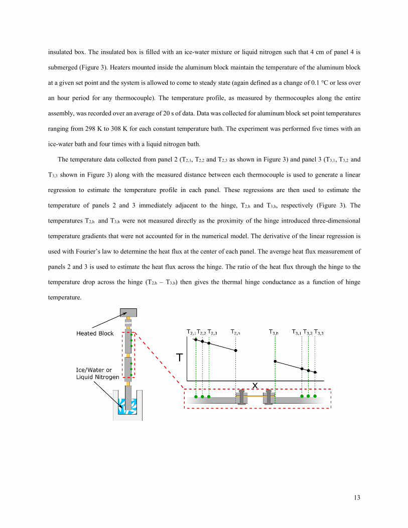
insulated box. The insulated box is filled with an ice-water mixture or liquid nitrogen such that 4 cm of panel 4 is
submerged (Figure 3). Heaters mounted inside the aluminum block maintain the temperature of the aluminum block
at a given set point and the system is allowed to come to steady state (again defined as a change of 0.1 °C or less over
an hour period for any thermocouple). The temperature profile, as measured by thermocouples along the entire
assembly, was recorded over an average of 20 s of data. Data was collected for aluminum block set point temperatures
ranging from 298 K to 308 K for each constant temperature bath. The experiment was performed five times with an
ice-water bath and four times with a liquid nitrogen bath.
The temperature data collected from panel 2 (T2,1, T2,2 and T2,3 as shown in Figure 3) and panel 3 (T3,1, T3,2 and
T3,3 shown in Figure 3) along with the measured distance between each thermocouple is used to generate a linear
regression to estimate the temperature profile in each panel. These regressions are then used to estimate the
temperature of panels 2 and 3 immediately adjacent to the hinge, T2,h and T3,h, respectively (Figure 3). The
temperatures T2,h and T3,h were not measured directly as the proximity of the hinge introduced three-dimensional
temperature gradients that were not accounted for in the numerical model. The derivative of the linear regression is
used with Fourier’s law to determine the heat flux at the center of each panel. The average heat flux measurement of
panels 2 and 3 is used to estimate the heat flux across the hinge. The ratio of the heat flux through the hinge to the
temperature drop across the hinge (T2,h – T3,h) then gives the thermal hinge conductance as a function of hinge
temperature.

14
Figure 3 – The experimental setup used to determine the hinge conductance with an inset depicting thermocouple placement and typical temperature distribution. The panel subsystem is insulated and suspended vertically such that panel 4 is partially submerged in an ice/water or liquid nitrogen bath. To determine the hinge conductance, three thermocouples are placed on panel 2 and panel 3 at a distance 2 cm apart. A linear regression derived from these measured temperatures gives an estimate of the temperature in the panels immediately adjacent to the hinge, T2,h and T3,h. Likewise, the derivative of the linear regressions is used with Fourier’s law to find the heat flux at the center of each panel. The ratio of the average heat flux value to the difference between T2,h and T3,h gives the hinge conductance as a function of hinge temperature.
2.5 Error and Uncertainty Analysis
Heater power measurements approximate the thermal radiation heat loss from the radiator panels and may be
compared with the output from the numerical model. For an accurate comparison, experimental heat losses from the
aluminum block must be quantified as well as the experimental error of the power and temperature measurements.
Likewise, the error of the numerical model with respect to the uncertainty in radiator dimensions and physical
properties must be accounted for.
2.5.1 Radiator Experiment Error and Uncertainty
The heater power (P) is reported as the average of 2 min of data, with data collected every 3.5 s. The uncertainty
of the power measurement is given as the first standard deviation over 2 min of heater power data. Likewise, the
heat lost from the aluminum block via conduction into the base through the fiberglass standoff is quantified with the
second term of Equation 2, using an approximation of Fourier’s Law. The temperature of the fiberglass baseboard is
assumed to be the temperature of the platen (Tsurr), the radius of the standoff is rs = 1.27 cm, the length of the
standoff is Ls = 2.54 cm, and the thermal conductivity of the standoff is ks = 1.059 W m-1 K-1. The radiative heat loss
from the aluminum block to the radiative insulation and then into the cold surroundings is given as the third term in
Equation 2, where the emissivity of the aluminum block (eb) is given as 0.20 – 0.33 for heavily-oxidized aluminum
[34], the emissivity of the MLI (em) is given as 0.015 – 0.030 [35], the surface area of the block is Ab = 0.012 m2
and the external surface area of the MLI is Am = 0.02 m2. These two heat loss terms are subtracted from the heat
power measurement to give the radiative cooling power of the radiator (qrad) as shown in Equation 2.
(2)
The uncertainty of an individual thermocouple measurement, such as the temperature at a given panel location or
the temperature of the surroundings, is the uncertainty of a T-type thermocouple (Omega), reported by the
( )4 422 1 11 2
b surrb surrrad s s
b ms
b b b m m
T TT Tq P k rL
A A A
sp e e
e e
--= - -
- -+ +

15
manufacturer as ±1° C. The uncertainty of the component temperature (Tb), which utilizes five temperature
measurements, is given with the root-sum-square of the five temperature measurement’s uncertainties using the
thermocouple uncertainty of ±1° C, giving a component temperature uncertainty of 0.44° C.
Regarding the radiator position uncertainty, the vacuum chamber used for testing featured four viewing ports
equally spaced around the perimeter of the cylindrical chamber. The height of the windows was such that a portion of
the radiator was always visible along the center-line of the windows. At each radiator position, two photographs were
obtained. The first image lies in the same plane as the scissoring mechanism. The struts of the scissor mechanism,
which were a known length, were used as a reference length. The angle of the actuation subsystem was measured
graphically by determining the angle between adjacent mechanism struts. The second image lies in the same plane as
the fully-extended panels, similar to the image in Figure 2a. The stainless-steel rods, again of a known length, were
used as a reference point and the vertical distance between adjacent steel rods and the known length of the aluminum
struts were used to measure the current angle of the actuation subsystem. Additionally, the actuation subsystem angle
was determined by counting revolutions of the stepper motor to determine changes in actuation distance. The average
of the three actuation subsystem angle measurements (2 photographic, 1 counting revolutions) was taken to be the
actual radiator position.
During experimentation, the angle was measured only for the actuation subsystem, but the angle utilized in the
numerical model is the angle of the panel subsystem. To account for the discrepancy between the angle of the actuation
and panel subsystems, the device was assembled outside of the vacuum environment and actuated to the smallest and
largest measured angles, as measured by counting the steps of the stepper motor. The angle of the actuation subsystem
as calculated using the photographic approach was then compared to the angle of the panel subsystem measured using
an angle protractor. The comparison was completed three times, with 11° as the greatest measured discrepancy
between the two angles.
The total uncertainty of the radiative cooling power is determined with the root-sum-square-method. Table 1
provides the numerical values for the uncertainty of each variable used in Equation 2.
Table 1 – The value and uncertainty for each variable found in Equation 2 as reported at 273 K. Sources are provided for uncertainties found in published works.
Variable Value Uncertainty (±) Source ks 1.059 (W m-1 K-1) 0.019 (W m-1 K-1) [36] Ls 0.0254 (m) 0.0005 (m) least-count uncertainty rs 0.0127 (m) 0.0005 (m) least-count uncertainty

16
eb 0.260 (-) 0.060 (-) [34] em 0.023 (-) 0.006 (-) [35] Ab 0.012 (m2) 0.000254 (m2) least-count uncertainty Am 0.020 (m2) 0.00028 (m2) least-count uncertainty
2.5.2 Numerical Model Uncertainty
The properties used to describe the physical radiator (panel length Lp, panel width wp, panel thickness tp, panel
emissivity ep, material thermal conductivity kp, hinge conductance κ) are inputs to the numerical model. To determine
the final uncertainty of the radiator heat transfer rate as determined by the numerical model, the influence of each
parameter’s uncertainty on the final result is quantified by the Method of Sequential Perturbations [37]. In this method,
an individual parameter, such as the emissivity, is increased by the uncertainty of the reported value and the numerical
model is executed, giving a heat transfer rate which accounts for the increased value of a single parameter. The
parameter value is then decreased below the reported value by the uncertainty of the parameter and the numerical
model is again executed. Half of the difference between the two model results gives the uncertainty of the result due
to the single test parameter, or the sensitivity index. This procedure is performed for each parameter, and the root-
sum-square of these values gives the total uncertainty of the numerical result. Table 2 reports the value and uncertainty
for each parameter used in the numerical model. For the panel thermal conductivity, the value was determined at a
temperature of 293 K using a correlation from [38] and the uncertainty is the difference between the value at 293 K
and the lowest temperature encountered by a panel, being 220 K.

17
Table 2 – The value and uncertainty for variables used as inputs to the numerical model. The panel thermal conductivity value is reported at a temperature of 293 K where the uncertainty of the value is the difference between the thermal conductivity at 293 K and at the lowest temperature encountered in analysis, 220 K.
Variable Value Uncertainty (±) Source Lp 0.102 (m) 0.00001 (m) least-count uncertainty wp 0.159 (m) 0.0005 (m) least-count uncertainty tp 0.0032 (m) 0.00001 (m) least-count uncertainty kp 220 (W m-1 K-1) 2 (W m-1 K-1) [28] ep 0.91 (-) 0.01 (-) [39] Tb 293 (K) 1 (K) manufacturer reported error κ 0.63 (W K-1) 0.19 (W K-1) propagated uncertainty
2.5.3 Hinge Thermal Conductance Uncertainty
The error of the experimentally determined hinge thermal conductance (as described in Section 2.4) must also be
quantified and utilized within the numerical model uncertainty analysis. The uncertainty of the measured distance
between thermocouples, given as the resolution error of the calipers used to measure this distance (± 0.5 mm), and the
uncertainty of the thermocouples (± 0.1 K), which were calibrated for this experiment, were used in conjunction with
the method of sequential perturbations to quantify the uncertainty of the hinge conductance. The uncertainty of the
thermal hinge conductance is reported in Table 2 and discussed in Section 3.2.
3 Results and Discussion
3.1 Radiator Experiment
Figure 4a illustrates the results of the variable heater power radiator experiment where thermal control via active
manipulation of a deployable surface is demonstrated. The radiative cooling power (qrad), being the heater power
minus the experimental loss terms (Equation 2), is given as the vertical axis on the right. The left vertical axis depicts
the temperature of the protected component, or the average of the five thermocouples placed on the heated aluminum
block. Both vertical axes are reported as a function of the radiator angle (f). The error of the radiative cooling power
is depicted as error bars, and the component temperature uncertainty, which is not depicted, is ±0.44° C. Finally, the
uncertainty of each measurement with respect to the radiator angle is ±6°. Figure 4b also depicts the temperature of
the protected component for the actuated radiator, now plotted with respect to the radiator cooling power. Likewise,
the temperature of the protected component for a stationary radiator at f = 147° is plotted. Again, the uncertainty of
each data point is ±0.44° C for the y-axis and ±3° for the x-axis.

18
The temperature of the aluminum block was maintained at a constant value by actively controlling the heater power
in response to variations in the radiator’s position. This approach incorporated a PID controller which significantly
reduced the time required to reach steady state conditions. However, in a spacecraft application, the device would be
utilized in the inverse control scenario, where the radiator’s position would be actively controlled in response to
variations in the waste heat load. However, the steady-state values for aluminum block temperature and radiative
cooling power as reported in Figure 4a would be identical for either control scenario. Figure 4a, therefore, illustrates
the capability of an actively controlled multi-panel radiator to maintain the steady state temperature of a spacecraft
component subjected to varying waste heat loads. This is evidenced by the constant temperature of the aluminum
block for an actively controlled radiator scenario. In contrast, the extended, stationary radiator (ϕ = 147°) was unable
to maintain the temperature of the aluminum block at a constant value as shown in Figure 4b. As the radiative cooling
power decreased from a maximum of 14.95 W to a minimum of 11.45 W, the temperature of the aluminum block
likewise decreased by a total of 23 K, a variation in temperature that may be too large for sensitive components such
as batteries, optics or processors [1]. In an applied scenario, this decrease in waste heat load, amounting to 3.5 W,
would need to be supplied by an equivalent increase from survival heaters attached to the protected component. This
survival heater power must be applied continuously whenever the waste heat load remains below the maximum value,
increasing the battery and solar panel capacity required by the spacecraft.
(a) (b)

19
(c)
Figure 4 – (a) Temperature of the protected component (Tb) as a function of radiator angle for a radiator with variable geometry. Radiative cooling power of the actuated radiator (qrad) as a function of the radiator angle is also reported using the right axis. Uncertainty of each temperature measurement is not depicted but is ±0.44 K for each data point. (b) Temperature of the protected component (Tb) as a function of radiator cooling power (qrad) for the actuated and stationary tests. In the actuated test (legend entry: “f = Variable Angle”), the radiator position varied as a function of radiator cooling power. In the stationary test, the radiator was fully extended (legend entry: “ϕ = 147°, near flat”) and the component temperature was allowed to decrease as the radiator cooling power decreased. (c) Temperature of the radiator as a function of position along the radiator for three radiator angle positions, where x = 0 corresponds to the center of the protected component. Data points at 10, 22, 35, and 48 cm correspond to the center of panels 1 – 4, respectively.
Figure 4a illustrates the heat transfer control potential of the device. From fully-extended (f = 147°) to fully-
retracted (f = 37°), the experimental prototype demonstrated a turn-down ratio of 1.32 (ratio of largest to smallest
cooling power). This value, however, does not reflect the true potential of the radiator. As seen in Figure 4a, the
variation in cooling power as a function of radiator angle is greatest for small radiator angles. For example, the radiator
cooling power decreased by only 0.08 W between f = 147° and f = 138°. However, when the radiator angle decreased
from f = 45° to f = 37°, the radiative cooling power decreased by 0.75 W. Further decreases in radiator angle below
the experimental limit would have resulted in significant decreases in radiative cooling power. Likewise, the vacuum
chamber shroud was maintained at a temperature of 173 K throughout testing. However, the radiator of a spacecraft
is generally exposed to deep space at an effective temperature of 4 K, and the temperature of the surroundings impacts
the turn-down ratio of the radiator. Results from the numerical model (Section 3.3) are used to predict the turn-down
ratio of the radiator for a larger range of radiator angles (5° < f < 180°) and for a surrounding temperature of 4 K (see
Table 3).

20
Figure 4c depicts the temperature profile of the radiator for three different radiator angles. The temperature at x =
0 cm correspond to the center of the aluminum block. Each successive x-location (10, 22, 36, and 48 cm) corresponds
to the midpoint of panels 1 – 4, respectively. The uncertainty of each temperature measurement is ± 1 K. As shown in
Figure 4c, the panel temperatures decrease as the radiator angle (and radiative cooling power) increases. This
decreasing temperature trend is due to the increased exposure of the panels as the radiator extends outwards. Likewise,
the difference between the temperatures of panel 1 and panel 4 increases from an initial value of 34 K at f = 37° to a
value of 42 K at f = 147°. Both of these temperature trends indicate a decrease in the radiative fin efficiency of the
device as the radiator angle increases, a phenomenon explained by the decreasing influence of inter-panel radiation
heat transfer as the radiator expands [26]. At small radiator angles, the panels are exposed almost entirely to adjacent
panels and energy is easily transferred along the length of the radiator via both heat conduction and thermal radiation
emission and absorption. However, as the radiator expands, the panels move away from each other, removing the
radiation coupling between panels and decreasing the total quantity of energy that is transferred from the radiator base
to the radiator tip. As such, a competing effect is observed, where the radiator fin efficiency decreases and the radiator
cooling power increases as the radiator angle increases.
3.2 Hinge Conductance Experiment
The hinge conductance test was completed five times for the ice-water bath and four times for the liquid nitrogen
bath with the aluminum block set to a temperature between 298 and 308 K. The average hinge conductance using the
ice-water bath data is 0.66 W K-1 with an average uncertainty of 0.03 W K-1 at an average hinge temperature of 289
K. For liquid nitrogen, the average hinge conductance is 0.62 W K-1 with an average uncertainty of 0.17 W K-1 at an
average hinge temperature of 230 K. These results indicate that the hinge conductance may decrease slightly as the
hinge temperature decreases, although the uncertainty of the low temperature result is larger than the measured
variation in hinge conductance with temperature. Although the hinge conductance data is not suitable to adequately
predict the relationship between temperature and hinge conductance with confidence (due to a weak temperature
dependence relative to the uncertainty), the full span of experimental hinge temperatures (220 – 280 K) is
approximately represented by the hinge conductance measurement data. As such, the numerical model utilized a mean
value for the hinge conductance of k = 0.63 W K-1 with a 30% uncertainty as determined by the largest relative
21
uncertainty value. In this manner, variation in hinge conductance with hinge temperature is accounted for in the
uncertainty of the numerical result.
As a general comparison, commercially available copper straps exhibit a thermal conductance of 0.168 W K-1 at a
temperature of 77 K where heat is transported over a distance of 0.057 m [40]. Likewise, a number of researchers have
developed flexible oscillating heat pipes with reported thermal conductance values (averaged over all tested power
levels and charge ratios) of 0.359 [30], 1.913 [31], 5.290 [32], and 62.53 [33] where heat is transported over distances
of 0.085 m, 1.070 m, 0.270 m, and 0.400 m respectively. However, these conductance values for the flexible oscillating
heat pipes were obtained for temperature ranges above 293 K.
(a) (b)
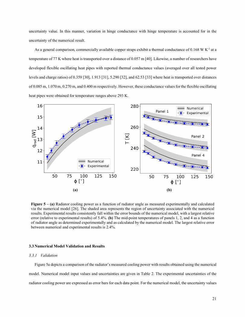
Figure 5 – (a) Radiator cooling power as a function of radiator angle as measured experimentally and calculated via the numerical model [26]. The shaded area represents the region of uncertainty associated with the numerical results. Experimental results consistently fall within the error bounds of the numerical model, with a largest relative error (relative to experimental results) of 5.4%. (b) The mid-point temperatures of panels 1, 2, and 4 as a function of radiator angle as determined experimentally and as calculated by the numerical model. The largest relative error between numerical and experimental results is 2.4%.
3.3 Numerical Model Validation and Results
3.3.1 Validation
Figure 5a depicts a comparison of the radiator’s measured cooling power with results obtained using the numerical
model. Numerical model input values and uncertainties are given in Table 2. The experimental uncertainties of the
radiator cooling power are expressed as error bars for each data point. For the numerical model, the uncertainty values

22
given in Table 2 and the measured uncertainty of the flexible hinge were used in conjunction with the method of
sequential perturbations (as described in section 2.5.2) to estimate the uncertainty of the numerical model results
(shaded region in Figure 5a). Likewise, Figure 5b depicts a comparison of the experimental and numerical panel
temperatures for the center-points of panels 1, 2, and 4 as a function of radiator angle. Uncertainty for each data point
is again expressed with error bars for experimental results and as a shaded region for numerical model results.
As shown in Figure 5a, the numerical and experimental approaches generally agree, with a worst-case discrepancy
of 0.68 W at a radiator angle of 53°, or 5.4% relative error compared to the experimental value, and all experimental
data points fall within the uncertainty of the numerical model. The difference between the measured and predicted
heat transfer values for the radiator cooling power is greatest for small radiator angles. Likewise, the turn-down ratio
as computed by the experimental data is 1.31, whereas the turn-down ratio as computed by the numerical model for
the same angle range is 1.39, or 6.1% relative difference. Figure 5b shows that the numerical model results and
experimental results for the temperature profile of the radiator agree to within the uncertainty estimates, indicating
that the numerical model is a valid predictor of the radiator’s cooling power and temperature profile. However, the
difference in the curvature of the numerical profile from the experimental profile may indicate that model does not
include some minor phenomena. The largest relative discrepancy between predicted and measured panel temperature
values is 2.4%. Likewise, the small discrepancy between the turn-down ratio values of the two approaches (6.1%
relative difference) suggests that the turn-down ratio predicted by the model is accurate for the specified radiator
design.
Several assumptions in the numerical model explain the discrepancy between the numerical and experimental
results. First, measurements suggest that the hinge conductance is a function of temperature, with the hinge
conductance decreasing as temperature decreases. Further, the temperature of the hinge connected to the aluminum
block (approximately the same temperature as the aluminum block) and the temperature of the hinge connecting panels
3 and 4 (mean value of panel 3 and panel 4 temperatures) differed by 41.3 K at f = 147° and 33.6 K at f = 37°. As
such, the average hinge temperature and, therefore, the average hinge thermal conductance varies as a function of
radiator angle. The numerical model, however, assumes a uniform conductance for all hinges in the radiator and uses
this same value for all tested radiator angles. Allowing for variation of the hinge thermal conductance as a function of
temperature would increase the fidelity of the model. However, the currently available hinge thermal conductance
data is not sufficient to model these effects. Regardless, improving the design of the flexible thermal hinges is

23
recommended. Second, the two-dimensional assumption used in the numerical model is undoubtedly responsible for
a portion of the disagreement. Previous research has shown that 2D origami heat transfer models used to describe 3D
geometries show the greatest error in the mid-range of radiator angles (30° < f < 90°); this corresponds to the region
showing the greatest disagreement between numerical and experimental results in the current work [22]. Third,
experimental conditions may also contribute to discrepancy between prediction and experiment. Specifically, the angle
between panels 3 and 4 was not always equivalent to the angle between panels 1 and 2 or between panels 2 and 3,
with a greatest reported discrepancy of 6°. In the small angle range (f < 50°), such variations in radiator angle leads
to discrepancies between the measured and predicted values. [23].
3.3.2 Model Results
With the numerical model validated experimentally, it may now be used to predict the radiative cooling power for
radiator angle ranges and surrounding temperatures that could not be tested experimentally (i.e. f < 37°, Tsurr = 4 K)
in order to find the turn-down ratio potential of a fully functional device. For an equivalent radiator comprised of the
same components, geometries, and surrounding temperature as was tested in this work but with the ability to actuate
from 180° to 5°, the numerical model predicts a turn-down ratio of 1.94 (qf=180° / qf=5°). Likewise, a radiator with the
same components and geometries but now in surroundings at 4 K and featuring full actuation achieves a turn-down
ratio of 2.27 (qf=180° / qf=5°).
The radiator’s current design has a possible turn-down ratio that falls below the values achieved by alternative
variable emissivity technologies. Recently-proposed vanadium oxide variable emissivity device achieves a turn-down
ratio of 7 [7]. Similarly, electrochromic coatings and other switching devices show turn-down ratios of 5 or lower
[11,41]. However, the current prototype might be improved through the use of more conductive materials for panel
construction, implementation of hinges with a larger conductance value, and the inclusion of additional radiating
panels. The numerical model was used to project the possible but realistic turn-down ratios of radiators with panels
constructed from highly conductive materials and hinges with larger conductance values. Likewise, each combination
of thermal conductivity and hinge conductance was tested for radiators with 2, 4, or 8 panels in order to demonstrate
the influence of number of panels on turn-down ratio. The combination of panel thermal conductivity, hinge
conductance, and number of panels for possible radiators is displayed in Table 3 along with the calculated turn-down
ratio. The case of a radiator with infinite thermal conductivity and infinite hinge conductance is also provided as a

24
reference bound. The temperature of the surroundings was maintained at 4 K while calculating the turn-down ratios
reported in Table 3 to simulate conditions typical of radiators aboard an orbiting spacecraft.
As seen in Table 3, the implementation of panel and hinge materials with greater conductivities increases the turn-
down potential of the device. For a panel constructed from a highly conductive material such as graphite (k = 1950 W
m-1 K-1) and with a hinge conductance value of 60, a turn-down ratio on the order of 3.70 is expected. This turn-down
ratio might be further increased by incorporating straight or oscillating [42,43] heat pipes inside of the panels, where
the maximum possible turn-down ratio for this geometry is 3.98. Adding additional radiator panels would significantly
increase the turn-down ratio of the device, although at the cost of additional weight (as shown in other work [26]).
Likewise, decreasing the number of panels decreases the expected turn-down ratio, although turn-down ratios up to 2
are still possible for a device with two panels. The hinge conductance values used in this analysis (0.6, 6, and 60) are
not representative of specific devices but represent the range of thermal conductance values available with proposed
or commercially available thermal hinges [30–33].
Table 3 – Predicted turn-down ratio for surroundings at 4 K, as measured from a radiator angle of 5° to 180°, for a radiator with 2, 4 or 8 panels having the same geometry as the current experiments but with four different panel thermal conductivities and four different hinge conductance values.
k [W K-1] 0.6 6 60 ∞ Panels 2 4 8 2 4 8 2 4 8 2 4 8
k p [W
m-1
K- 1
] 237 1.81 2.27 2.46 1.95 2.82 3.34 1.97 2.93 3.55 1.97 2.95 3.58
401 1.82 2.32 2.55 1.96 3.02 3.77 1.98 3.19 4.14 1.99 3.21 4.19
1950 1.82 2.39 2.67 1.97 3.38 4.82 1.99 3.70 6.01 1.99 3.74 6.22
∞ 1.82 2.41 2.71 1.97 3.52 5.37 1.99 3.92 7.46 2.00 3.98 7.92
3.4 Design and Application Considerations
Controlled deployable surfaces feature several application-specific advantages not illustrated by the experimental
or numerical data provided by this work. First, deployable surfaces have been used in spacecraft for decades, indicating
a certain degree of space heritage. As an example, the International Space Station utilizes deployable radiators, where
the panels were retracted for stowage prior to launch and then deployed upon installment via a cable and winch system
(Figure 1). Likewise, solar panels, communication arrays, and even optical components of numerous spacecraft offer
deployable features to enable functionality [44]. These technologies, however, require a one-time deployment upon
orbit insertion, whereas a dynamic radiator requires intermittent variation of geometry. As such, a final radiator design

25
must be robust, accounting for wear on the hinges from continuous use while providing a measure of redundancy in
the case of hinge or actuating system failure.
Second, origami-inspired dynamic radiators are functionalized entirely by variations in geometry and therefore
may be constructed from simple, inexpensive materials. As such, this technology could be easily and economically
scaled to match the heat transfer requirements of any spacecraft. Likewise, deployable surfaces might be combined
with other radiative heat transfer control technologies that utilize separate mechanisms. As an example, an actively or
passively controlled deployable radiator might be coated with a thermochromic or electrochromic surface. Such a
device would utilize variations in emitting radiative area as well as variations in surface intrinsic radiative surface
properties. Acting in parallel, the heat transfer control mechanisms could increase the total turn-down ratio potential
while providing multiple functional states for a given radiator position.
Finally, actively-controlled surfaces have the capability of rapid mobilization, enabling real-time matching of
waste heat loads. Likewise, actively-controlled surfaces may be positioned in advantageous configurations previous
to variations in thermal loads. Passive technologies require a variation in temperature to achieve actuation or
reconfiguration and, therefore, the change in radiative behavior can be later than is desirable.
As previously identified, the current radiator prototype likely requires modification before implementation in
spacecraft. Future work will include weight reduction while maximizing turn-down ratio. Possible modifications
include variation of panel geometries and materials, adoption of high-performance hinge materials (such as flexible
oscillating heat pipes [32]) and re-design of the actuation system. The accordion tessellation was selected to
demonstrate the behavior of origami-inspired radiators due to its simplicity of construction/actuation and because
published results regarding its heat transfer behavior exist [26]. However, the accordion tessellation required a support
structure for positioning due to its multiple degrees of freedom (see Figure 2b). Alternative tessellations that offer
“conceal and reveal” behavior [45] with lower degrees of freedom offer the potential for (1) weight reduction through
cable-driven actuation methods without the need for a heavy support structure and (2) utilization of panels actuated in
parallel as opposed to in series.
4 Conclusions
The performance of a multi-panel, actively deployed radiator was investigated experimentally and numerically.
With the surrounding at 173 K, the radiator cooling power of a four-panel prototype radiator decreases as the radiator

26
collapses. The measured turn-down ratio was 1.31 over a restricted to actuation range between f = 37° to f = 147°.
Based on results obtained using a validated model, the turn-down ratio of the prototype would be 2.27 when it is
actuated between f = 5° to 180° and deployed in a lower temperature environment (Tsurr = 4 K). Also, the use of an
actively-controlled dynamic radiator to achieve constant temperature conditions for a protected component
experiencing varying waste heat loads was demonstrated. Such a device would reduce power consumed by survival
heaters that are currently deployed on orbiting spacecraft. Temperature measurements verified that the fin efficiency
of the device decreases as the radiator extends towards a fully-open position, which is a result of the decrease in the
radiative transfer between panels. Finally, the use of improved panel materials, hinge materials, and number of radiator
panels was explored numerically. These numerical results indicate turn-down ratios as high as 1.99, 3.70, and 6.01 for
a two, four, and eight panel radiators are achievable if the performance of the thermal hinges is improved with use of
highly conductive materials. Assuming infinite thermal conductivity and thermal conductance, a two, four or eight
panel radiator will have a maximum turn-down ratio of 2.0, 3.98, and 7.92, respectively when rejecting heat to deep
space at 4 K.
Acknowledgments
This material is based upon work supported by a NASA Space Technology Research Fellowship (grant number
NNX15AP49H) and the National Science Foundation (grant number 1749395). The authors would like to thank Omar
Quinones, Mario Martins, and Frank Robins of NASA Goddard whose help with thermal modelling and vacuum
experimentation was essential to the success of this work.

27
References
[1] D.G. Gilmore, Spacecraft Thermal Control Handbook, 2nd ed., The Aerospace Corporation Press, El Segundo,
CA, 2002.
[2] L.M. Grob, T.D. Swanson, Parametric study of variable emissivity radiator surfaces, in: M.S. El-Genck (Ed.),
Sp. Technol. Appl. Int. Forum, American Institute of Physics, Albuquerque, NM, 2000: pp. 809–814.
doi:10.1063/1.1302579.
[3] R.L. Voti, G.L. Leahu, M.C. Larciprete, C. Sibilia, M. Bertolotti, Photothermal characterization of
thermochromic materials for tunable thermal devices, Int. J. Thermophys. 36 (2015) 1004–1015.
doi:10.1007/s10765-014-1790-2.
[4] R.L. Voti, M.C. Larciprete, G. Leahu, C. Sibilia, M. Bertolotti, Optimization of thermochromic VO2 based
structures with tunable thermal emissivity, J. Appl. Phys. 112 (2012) 034305. doi:10.1063/1.4739489.
[5] M. Benkahoul, M. Chaker, J. Margot, E. Haddad, R. Kruzelecky, B. Wong, W. Jamroz, P. Poinas,
Thermochromic VO2 film deposited on Al with tunable thermal emissivity for space applications, Sol. Energy
Mater. Sol. Cells. 95 (2011) 3504–3508. doi:10.1016/j.solmat.2011.08.014.
[6] A.S. Barker, H.W. Verleur, H.J. Guggenheim, Infrared optical properties of vanadium dioxide above and
below the transition temperature, Phys. Rev. Lett. 17 (1966) 1286–1289. doi:10.1103/PhysRevLett.17.1286.
[7] S. Taylor, Y. Yang, L. Wang, Vanadium dioxide based Fabry-Perot emitter for dynamic radiative cooling
applications, J. Quant. Spectrosc. Radiat. Transf. 197 (2017) 76–83. doi:10.1016/j.jqsrt.2017.01.014.
[8] H. Demiryont, D. Moorehead, Electrochromic emissivity modulator for spacecraft thermal management, Sol.
Energy Mater. Sol. Cells. 93 (2009) 2075–2078. doi:10.1016/j.solmat.2009.02.025.
[9] J.S. Hale, M. DeVries, B. Dworak, J.A. Woollam, Visible and infrared optical constants of electrochromic
materials for emissivity modulation applications, Thin Solid Films. 313 (1998) 205–209.
[10] N. Kislov, H. Groger, R. Ponnappan, All-solid-state electrochromic variable emittance coatings for thermal
management in space, Sp. Technol. Appl. Int. Forum - Staif 2003. 654 (2003) 172–179.
doi:10.1063/1.1541292.
[11] P. Chandrasekhar, B.J. Zay, D. Lawrence, E. Caldwell, R. Sheth, R. Stephan, J. Cornwell, Variable-emittance
infrared electrochromic skins combining unique conducting polymers, ionic liquid electrolytes, microporous
polymer membranes, and semiconductor/polymer coatings, for spacecraft thermal control, J. Appl. Polym.

28
Sci. 131 (2014). doi:10.1002/app.40850.
[12] M. Amidieu, B. Moschetti, Development of a deployable radiator using a L.H.P as heat transfer element, in:
T.D. Guyenne (Ed.), Sixth Eur. Symp. Sp. Environ. Control Syst., European Space Agency, Noordwijk, The
Netherlands, 1997: pp. 283–288.
[13] K. Lee, Y. Li, B.J. Guzek, J.R. Kadambi, Y. Kamotani, Compact heat rejection system utilizing integral
variable conductance planar heat pipe radiator for space application, Gravitational Sp. Res. 3 (2015) 30–41.
[14] R.P. Reysa, R.L. Thurman, International space station environmental control and life support and thermal
control systems overview, in: T.D. Guyenne (Ed.), Sixth Eur. Symp. Sp. Environ. Control Syst., European
Space Agency, Noordwijk, The Netherlands, 1997: pp. 11–28.
[15] G.B. Ganapathi, E.T. Sunada, G.C. Birur, J.R. Miller, R. Stephan, Design description and initial
characterization testing of an active heat rejection radiator with digital turn-down capability, Int. J. Aerosp. 4
(2009) 272–278. doi:10.4271/2009-01-2419.
[16] H. Nagano, A. Ohnishi, Y. Nagasaka, Development of a lightweight deployable/stowable radiator for
interplanetary exploration, Appl. Therm. Eng. 31 (2011) 3322–3331.
doi:10.1016/j.applthermaleng.2011.06.012.
[17] R. Ponnappan, J.E. Beam, E.T. Mahefkey, Roll-out-fin expandable space radiator concept, J. Thermophys.
Heat Transf. 2 (1988) 91–94.
[18] C. Bertagne, P. Walgren, L. Erickson, R. Sheth, J. Whitcomb, D. Hartl, Coupled behavior of shape memory
alloy-based morphing spacecraft radiators: Experimental assessment and analysis, Smart Mater. Struct. 27
(2018) 065006. doi:10.1088/1361-665X/aabbe8.
[19] N. Athanasopoulos, N.J. Siakavellas, Smart patterned surfaces with programmable thermal emissivity and
their design through combinatorial strategies, Sci. Rep. 7 (2017) 1–30. doi:10.1038/s41598-017-13132-6.
[20] D. Chittenden, G. Grossman, E. Rossel, P. Van Etten, G. Williams, P.V.A.N. Etten, G. Williams, High power
inflatable radiator for thermal rejection from space power systems, in: D.Y. Goswami (Ed.), 23rd Intersoc.
Energy Convers. Eng. Conf., ASME, 1989: pp. 353–358.
[21] R.B. Mulford, L.G. Christensen, M.R. Jones, B.D. Iverson, Dynamic control of radiative surface properties
with origami-inspired design, J. Heat Transfer. 138 (2016) 32701. doi:10.1115/1.4031749.
[22] B.D. Iverson, R.B. Mulford, E.T. Lee, M.R. Jones, Adaptive net radiative heat transfer and thermal
29
management with origami-structured surfaces, in: Proc. 16th Int. Heat Transf. Conf., Beijing, China, 2018:
pp. 1–9.
[23] R.B. Mulford, V.H. Dwivedi, M.R. Jones, B.D. Iverson, Control of net radiative heat transfer with a variable
emissivity accordion tessellation, J. Heat Transfer. 141 (2019) 032702. doi:10.1115/1.4042442.
[24] R.B. Mulford, N.S. Collins, M.S. Farnsworth, M.R. Jones, B.D. Iverson, Total hemispherical apparent
radiative properties of the infinite V-groove with specular reflection, Int. J. Heat Mass Transf. 124 (2018)
168–176. doi:10.1016/j.ijheatmasstransfer.2018.03.041.
[25] R.B. Mulford, N.S. Collins, M.S. Farnsworth, M.R. Jones, B.D. Iverson, Total hemispherical apparent
radiative properties of the infinite V-groove with diffuse reflection, J. Thermophys. Heat Transf. 32 (2018)
1108–1112. doi:10.2514/1.T5485.
[26] R.B. Mulford, M.R. Jones, B.D. Iverson, Heat transfer, efficiency and turn-down ratio of a dynamic radiative
heat exchanger, Int. J. Heat Mass Transf. 143 (2019) 118441. doi:10.1016/j.ijheatmasstransfer.2019.118441.
[27] NASA, View of the aft EEATCS radiator deployment, Archive.Org. (2001). https://archive.org/details/sts098-
335-015 (accessed February 4, 2019).
[28] J.R. Davis, Metals Handbook Desk Edition, 2nd ed., ASM International, Materials Park, OH, 1998.
[29] T.L. Bergman, A.S. Lavine, F.P. Incropera, D.P. DeWitt, Fundamentals of Heat and Mass Transfer, 7th ed.,
Wiley, Hoboken, NJ, 2011.
[30] J. Lim, S.J. Kim, Fabrication and experimental evaluation of a polymer-based flexible pulsating heat pipe,
Energy Convers. Manag. 156 (2018) 358–364. doi:10.1016/j.enconman.2017.11.022.
[31] J. Qu, X. Li, Y. Cui, Q. Wang, Design and experimental study on a hybrid flexible oscillating heat pipe, Int.
J. Heat Mass Transf. 107 (2017) 640–645. doi:10.1016/j.ijheatmasstransfer.2016.11.076.
[32] T. Jaipurkar, P. Kant, S. Khandekar, B. Bhattacharya, S. Paralikar, Thermo-mechanical design and
characterization of flexible heat pipes, Appl. Therm. Eng. 126 (2017) 1199–1208.
doi:10.1016/j.applthermaleng.2017.01.036.
[33] C. Yang, C. Song, W. Shang, P. Tao, T. Deng, Flexible heat pipes with integrated bioinspired design, Prog.
Nat. Sci. Mater. Int. 25 (2015) 51–57. doi:10.1016/j.pnsc.2015.01.011.
[34] J.R. Howell, R. Siegel, M.P. Menguc, Thermal Radiation Heat Transfer, CRC Press, Boca Raton, FL, 2011.
[35] T.H. Takeshi Miyakita, Ryuta Hatakenaka, Hiroyuki Sugita, Masanori Saitoh, Evaluation of thermal
30
insulation performance of a new multi-layer insulation with non-interlayer-contact spacer, in: 45th Int. Conf.
Environ. Syst., ICES, Belleue, Washington, 2015: p. ICES-2015-220.
[36] F. Sarvar, N.J. Poole, P.A. Witting, PCB glass-fibre laminates: thermal conductivity measurements and their
effect on simulation, J. Electron. Mater. 19 (1990) 1345–1350. doi:10.1007/BF02662823.
[37] R.S. Figliola, D.E. Beasley, Theory and Design for Mechanical Measurements, 4th ed., Wiley, Hoboken, NJ,
2006.
[38] S.I. Abu-Eishah, Correlations for the thermal conductivity of metals as a function of temperature, Int. J.
Thermophys. 22 (2001) 1855–1868. doi:10.1023/A:1013155404019.
[39] G.C. Tuan, D.T. Westheimer, G.C. Birur, D.E. Beach, D.A. Jaworske, W.C. Peters, T.J. J., Evaluation of
coatings and materials for future radiators, J. Aerosp. 115 (2006) 83–94.
[40] B. Williams, S. Jensen, M. Chadek, J.C. Batty, Solderless flexible thermal links, Cryogenics (Guildf). 36
(1996) 867–869. doi:10.1016/0011-2275(96)00050-1.
[41] H. Li, K. Xie, Y. Pan, H. Wang, H. Wang, Study of the mechanism of the variable emissivity infrared
electrochromic device based on polyaniline conducting polymer, Synth. Met. 162 (2012) 22–25.
doi:10.1016/j.synthmet.2011.11.002.
[42] C. Yang, C. Chang, C. Song, W. Shang, J. Wu, P. Tao, T. Deng, Fabrication and performance evaluation of
flexible heat pipes for potential thermal control of foldable electronics, Appl. Therm. Eng. 95 (2016) 445–
453. doi:10.1016/j.applthermaleng.2015.11.078.
[43] K.A. Stevens, S.M. Smith, B.S. Taft, Variation in oscillating heat pipe performance, Appl. Therm. Eng. 149
(2019) 987–995. doi:10.1016/j.applthermaleng.2018.12.113.
[44] L. Puig, A. Barton, N. Rando, A review on large deployable structures for astrophysics missions, Acta
Astronaut. 67 (2010) 12–26. doi:10.1016/j.actaastro.2010.02.021.
[45] B.P. DeFigueiredo, N.A. Pehrson, K.A. Tolman, E. Crampton, S.P. Magleby, L.L. Howell, Origami-Based
Design of Conceal-and-Reveal Systems, J. Mech. Robot. (2019). doi:10.1115/1.4042427.