EXPERIMENTAL ANALYSIS OF LIQUID CARRY-OVER IN GAS-LIQUID CYLINDRICAL CYCLONE...
14
International Journal of ISSN 0974-2107 Systems and Technologies Vol.1, No.2, pp 1-14 1 IJST KLEF 2008 EXPERIMENTAL ANALYSIS OF LIQUID CARRY-OVER IN GAS-LIQUID CYLINDRICAL CYCLONE SEPARATORS Srinivas Swaroop Kolla * , Ram S. Mohan † , Ovadia Shoham ‡ , Shoubo Wang § , Luis Gomez ** ABSTRACT: PREDICTION OF THE OPERATIONAL ENVELOP FOR LIQUID CARRY-OVER IS ESSENTIAL FOR PROPER OPERATION OF GAS-LIQUID CYLINDRICAL CYCLONE (GLCC) COMPACT SEPARATORS. A SERIES OF EXPERIMENTS WERE CONDUCTED TO EVALUATE THE PERFORMANCE OF GLCC LIQUID CARRY-OVER FOR THREE-PHASE GAS-OIL-WATER FLOW. EXPERIMENTAL DATA WERE ACQUIRED IN A 3” DIAMETER GLCC FOR THE OPERATIONAL ENVELOP FOR LIQUID CARRY-OVER, UNDER THREE-P †† HASE FLOW. BOTH LIGHT OIL AND HEAVY OIL WERE UTILIZED, WITH WATERCUTS RANGING FROM 0 TO 100 %. THE LIQUID LEVEL WAS CONTROLLED AT 6” BELOW THE GLCC INLET. A SIGNIFICANT EFFECT OF WATERCUT ON THE OPERATIONAL ENVELOP FOR LIQUID CARRY-OVER FOR THREE-PHASE FLOW HAS BEEN OBSERVED. AS THE WATERCUT REDUCES, THE OPERATIONAL ENVELOP FOR LIQUID CARRY-OVER REDUCES, TOO. ALSO, THE OPERATIONAL ENVELOP FOR HEAVY OIL REDUCES AS COMPARED TO LIGHT OIL WHICH COULD BE PRIMARY DUE TO THE EFFECT OF VISCOSITY. FINALLY, THE ANNULAR MIST VELOCITY INCREASES WITH SURFACE TENSION. INTRODUCTION The Gas-Liquid Cylindrical Cyclone (GLCC) Separator technology has been an emerging technology in the petroleum industry. Its rise has been very promising to meet the ever increasing demands of petroleum industry, thus providing an attractive alternative to the conventional separator which has been in industry for more than 100 years. The GLCC separator is a vertically installed pipe mounted with a downward inclined tangential inlet, with outlets for gas and liquid provided at the top and bottom respectively. The two phases of the incoming mixture are separated due to the centrifugal/ buoyancy forces caused by the swirling motion. The liquid is forced radially towards the wall of the cylinder and is collected from the bottom, while the gas moves to the center of the cyclone and is taken out from the top of the GLCC. Significant advantages of the GLCC’s are its compact lower weight, ease of operation, and lower cost when compared to conventional separators.
Transcript of EXPERIMENTAL ANALYSIS OF LIQUID CARRY-OVER IN GAS-LIQUID CYLINDRICAL CYCLONE...

International Journal of ISSN 0974-2107
Systems and Technologies
Vol.1, No.2, pp 1-14
1
IJST
KLEF 2008
EXPERIMENTAL ANALYSIS OF LIQUID CARRY-OVER IN
GAS-LIQUID CYLINDRICAL CYCLONE SEPARATORS
Srinivas Swaroop Kolla
*, Ram S. Mohan
†,
Ovadia Shoham‡, Shoubo Wang
§, Luis Gomez
**
ABSTRACT: PREDICTION OF THE OPERATIONAL ENVELOP FOR LIQUID
CARRY-OVER IS ESSENTIAL FOR PROPER OPERATION OF GAS-LIQUID
CYLINDRICAL CYCLONE (GLCC) COMPACT SEPARATORS. A SERIES OF
EXPERIMENTS WERE CONDUCTED TO EVALUATE THE PERFORMANCE OF
GLCC LIQUID CARRY-OVER FOR THREE-PHASE GAS-OIL-WATER FLOW.
EXPERIMENTAL DATA WERE ACQUIRED IN A 3” DIAMETER GLCC FOR THE
OPERATIONAL ENVELOP FOR LIQUID CARRY-OVER, UNDER THREE-P††
HASE
FLOW. BOTH LIGHT OIL AND HEAVY OIL WERE UTILIZED, WITH WATERCUTS
RANGING FROM 0 TO 100 %. THE LIQUID LEVEL WAS CONTROLLED AT 6”
BELOW THE GLCC INLET. A SIGNIFICANT EFFECT OF WATERCUT ON THE
OPERATIONAL ENVELOP FOR LIQUID CARRY-OVER FOR THREE-PHASE FLOW
HAS BEEN OBSERVED. AS THE WATERCUT REDUCES, THE OPERATIONAL
ENVELOP FOR LIQUID CARRY-OVER REDUCES, TOO. ALSO, THE
OPERATIONAL ENVELOP FOR HEAVY OIL REDUCES AS COMPARED TO LIGHT
OIL WHICH COULD BE PRIMARY DUE TO THE EFFECT OF VISCOSITY.
FINALLY, THE ANNULAR MIST VELOCITY INCREASES WITH SURFACE
TENSION.
INTRODUCTION
The Gas-Liquid Cylindrical Cyclone (GLCC) Separator technology has been an
emerging technology in the petroleum industry. Its rise has been very promising to meet the
ever increasing demands of petroleum industry, thus providing an attractive alternative to the
conventional separator which has been in industry for more than 100 years. The GLCC
separator is a vertically installed pipe mounted with a downward inclined tangential inlet,
with outlets for gas and liquid provided at the top and bottom respectively. The two phases of
the incoming mixture are separated due to the centrifugal/ buoyancy forces caused by the
swirling motion. The liquid is forced radially towards the wall of the cylinder and is collected
from the bottom, while the gas moves to the center of the cyclone and is taken out from the
top of the GLCC. Significant advantages of the GLCC’s are its compact
lower weight, ease of operation, and lower cost when compared to conventional separators.
Experimental analysis of liquid
2
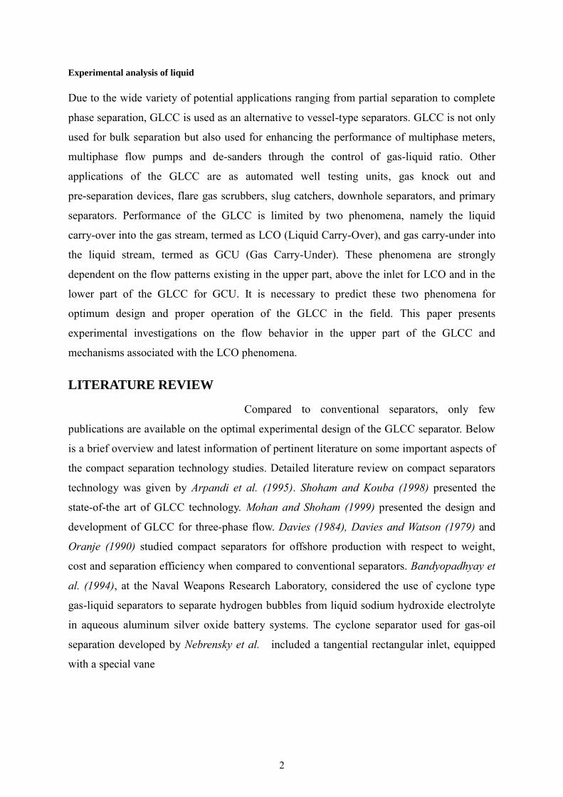
Due to the wide variety of potential applications ranging from partial separation to complete
phase separation, GLCC is used as an alternative to vessel-type separators. GLCC is not only
used for bulk separation but also used for enhancing the performance of multiphase meters,
multiphase flow pumps and de-sanders through the control of gas-liquid ratio. Other
applications of the GLCC are as automated well testing units, gas knock out and
pre-separation devices, flare gas scrubbers, slug catchers, downhole separators, and primary
separators. Performance of the GLCC is limited by two phenomena, namely the liquid
carry-over into the gas stream, termed as LCO (Liquid Carry-Over), and gas carry-under into
the liquid stream, termed as GCU (Gas Carry-Under). These phenomena are strongly
dependent on the flow patterns existing in the upper part, above the inlet for LCO and in the
lower part of the GLCC for GCU. It is necessary to predict these two phenomena for
optimum design and proper operation of the GLCC in the field. This paper presents
experimental investigations on the flow behavior in the upper part of the GLCC and
mechanisms associated with the LCO phenomena.
LITERATURE REVIEW
Compared to conventional separators, only few
publications are available on the optimal experimental design of the GLCC separator. Below
is a brief overview and latest information of pertinent literature on some important aspects of
the compact separation technology studies. Detailed literature review on compact separators
technology was given by Arpandi et al. (1995). Shoham and Kouba (1998) presented the
state-of-the art of GLCC technology. Mohan and Shoham (1999) presented the design and
development of GLCC for three-phase flow. Davies (1984), Davies and Watson (1979) and
Oranje (1990) studied compact separators for offshore production with respect to weight,
cost and separation efficiency when compared to conventional separators. Bandyopadhyay et
al. (1994), at the Naval Weapons Research Laboratory, considered the use of cyclone type
gas-liquid separators to separate hydrogen bubbles from liquid sodium hydroxide electrolyte
in aqueous aluminum silver oxide battery systems. The cyclone separator used for gas-oil
separation developed by Nebrensky et al. included a tangential rectangular inlet, equipped
with a special vane

Experimental analysis of liquid
3
and shroud arrangement to change the inlet area, which allowed control of the inlet velocity
independent of the throughput, and extended the operating range of the separator. A hollow
gas-liquid separator with rectangular tangential inlet near the bottom of the separator has
been developed by Zhikarev et al. (1985). A cylindrical cyclone with spiral vane internals
called auger separator was developed by ARCO (Kolpak, 1994) and exhibited 2% to 18% gas
carry under when tested in Alaska. Weingarten et al. (1995) explored alternatives to
conventional methods of controlling liquid level inside separators by using throttling floats
and throttling diaphragm valves operated by the vessel hydrostatic head. Arato and Barnes
(1992) used an in-line free vortex separator downstream of a centrifugal multiphase pump for
gas-liquid separation. Davies and Watson (1979) developed miniaturized compact separators
for offshore platforms which require less space than conventional separators. Chevron has
successfully built and operated several GLCC’s in low GOR flow metering applications. Liu
and Kouba (1994) and Kouba (1995) from Chevron conducted various studies for the
development of multiphase metering loop incorporating the Net Oil Computer, where gas and
liquid phases are separated by means of a GLCC separator and separately metered by gas and
liquid flow meters prior to recombination for transport.A 6-inch diameter and 12-ft high
single inlet GLCC at Texaco Humble test facility was used (Kouba, 2002) to measure gas
carry-under for various combinations of crude oil, water and natural gas using nuclear
densitometers located at the inlet vertical riser and pipe section of the GLCC liquid exit.
Colorado Engineering Experimental Station Inc. (CEESI) tested (Wang et al., (2002a) a
6-inch dual inlet GLCC at pressures of 200 to 1000 psi, with natural gas and decane. Gas and
liquid flow rates ranging from 34 Mscfd and 2000 bbld, respectively, were used to test a
6-inch dual inlet GLCC multiphase metering system at Daqing oil field experiment station
with natural gas and crude oil for watercuts from 0 to 100 % (Wang et al., 2006). A 60 in. ID
and 20 ft tall GLCC, largest in the world was employed at Minas for bulk separation/metering
(Marrelli et al., 2000). This GLCC operated at 170 psia and 260oF, handling liquid and gas
production rates of 160,000 bpd and 70 MMscfd, respectively and is equipped with control
valves on the gas and liquid legs and a sophisticated control system for liquid level control.
GLCC’s were designed for Duri, Indonesia field to handle both sand production and terrain
slugging.Sensitivity Analysis of conventional separators vs. GLCC demonstrated that its
application for Duri Area-10 alone was estimated to improve the metering accuary
considerable and save about $3.2 million over conventional separators. A 12-inch diameter

Experimental analysis of liquid
4
and 12-ft high dual inlet wet gas configuration of the GLCC was installed for metering
application by CNOOC on an offshore platform in China (Wang and Zhang, 2005). The first
subsea GLCC application designed and constructed by Curtiss Wright (Campen et al., 2006)
has been developed by joint industry project led by Petrobras and is located downstream of
the multiphase pump, separating and recalculating liquid from its liquid outlet back in to the
pump suction.
EXPERIEMENTAL PROGRAM
The Experimental data were acquired using advanced state-of-the-art instrumentation and
data acquisition system in a three-phase experimental flow loop as shown in Figure
Experimental Facility
The experimental flow loop comprises of a metering section to measure the single phase gas and
liquid flow rates and a GLCC test section.
Metering Section
The metering section consists of three parallel, single phase feeder lines for
measuring the incoming single-phase gas and liquid flow rates. Three phase mixture is
formed at the mixing tee and delivered to the GLCC test section. Air is used as the gas phase,
which is supplied to a gas tank by an air compressor with a capacity of 250 cfm at 108 psia.
The gas flow rate into the loop is controlled by a control valve and metered utilizing Micro
Motion®
mass flow meter. The liquid phases are mineral oil of specific gravity 0.854 and
water. The two liquid phases are supplied from 400 gallon storage tanks at atmospheric
pressure, and pumped to the liquid feeder lines with centrifugal pumps. Similar to the gas
phase, liquid rate is controlled by separate control valves and metered using respective Micro
MotionR
mass flow meters. The single phase gas and liquid streams are combined at the
mixing tee. Check valves located downstream of each feeder are provided in order to prevent
probable backflow. The three phase mixture downstream of test section is separated utilizing
a conventional three-phase separator. Gas is vented into the
atmosphere and liquid is returned to the storage tank to complete the cycle.
GLCC Test Section: The test section, as shown in Figure 1, comprises of a GLCC separator, in
a multiphase flow metering loop configuration. The test section is divided as follows

Experimental analysis of liquid
5
Figure 1. Schematic of GLCC Test Section
1. Inlet Section: The Inlet of the GLCC consists of an Inlet pipe section, 3” diameter
connected to the GLCC with an inlet having a sector-slot/plate configuration, with a nozzle
area of 25% of the inlet pipe cross-sectional area. The inlet section of the GLCC is shown in
Figure 2.
2. GLCC Body, Gas Leg and Liquid legs: The GLCC body is 3” diameter and 8’ tall as
shown in Figure 3.5. The gas leg is a 2” diameter pipe and it has a gas control valve (GCV).
On the other hand, the liquid leg consists of 2” diameter pipe sections. The Coriolis Micro
Motion® mass flow meters are located on both gas leg and liquid leg to measure the gas and
liquid outflow rates respectively.
8
”
24”
48
”
6
”
24”
THREE-PHASE
INLET
THREE-PHASE
OUTLET
GLCC
3’’

Experimental analysis of liquid
6
Figure 2. GLCC Inlet Section and Body
3. Control System: The main objective of the control system is to maintain the liquid level in
the GLCC by using the Control Valve. There are two simple control strategies and two
integrated control strategies mentioned below. Each of the control strategies explained below
has one final aim i.e. to control the liquid level in the GLCC. An integrated liquid level and
pressure control by LCV and GCV i.e. the third kind is used to conduct experiments.
Physical Phenomena
The Performance of GLCC is limited by two undesirable physical
phenomena namely Liquid Carry-Over (LCO) in the gas outlet stream and Gas Carry-Under
(GCU) in the liquid outlet stream. The ability to predict these two phenomena will ensure
optimum design parameters for the operation of the GLCC.
Liquid Carry-Over (LCO)
Initiation of liquid entrainment into the discharged gas stream at
the top of GLCC is called as Liquid Carry-Over (LCO). LCO plays an important role in the
analysis of the performance of the GLCC. The current study is concentrated on capturing the
effect of oil properties and the effect of watercut on the liquid carry over operational envelop
of a GLCC in which the liquid level and pressure are controlled.

Experimental analysis of liquid
7
Operational Envelope: The operational envelop for liquid carry-over is defined as the loci of
vsl and vsg for which the liquid starts to get carried into the gas leg. It occurs under extreme
operating conditions of high gas and/or high liquid flow rates. Plotting the loci of the liquid
and gas flow rates at which LCO is initiated provides the operational envelop for liquid carry
over as illustrated in the Figure 3.
Figure 3. Operational Envelop for Light Oil with Different Watercuts
The area below the operational envelope (OPEN) is the region of normal operating
condition (NOC). In this region, there is no liquid carry over in the separator. The region
above the OPEN represents the flow conditions for continuous LCO. Point (a) in the figure
represents NOC in the GLCC. Point (b) marks the initiation of the LCO phenomena in the
GLCC. This point represents the minimum gas flow rate required to initiate LCO for a given
liquid flow rate. For higher gas flow rate at point (c), the liquid is carried over in to the gas
stream continuously.
Flow regimes in GLCC: There are two distinct flow regimes responsible for liquid carry over
in the upper part of the GLCC. At relatively high liquid and low gas flow rates, the liquid
churns up and down in the upper part of the GLCC which is termed
as Churn Flow. Under this condition, liquid is carried over in to the gas leg in the form of
churn flow. This phenomenon is presented in Figure 4. At relatively high gas and low liquid
flow rates, the flow pattern in the upper part of the GLCC is annular flow. Under this
condition liquid is carried over into the gas stream and through the gas leg in the form of
droplets as shown in Figure 5.
LCO REGION
(a)
(b)
(c)
vsg
vsl

Experimental analysis of liquid
8
LIQUID IN GAS
LIQUID
LIQUID IN GAS
LIQUID
LIQUID IN GAS
LIQUID
LIQUID IN GAS
LIQUID
Fig 4. Schematic of Churn Flow in GLCC Fig 5.Schematic of Annular Flow in GLCC
EXPERIEMENTAL RESULTS AND DISCUSSION
The experimental results of effect of fluid properties and watercut are presented along
with discussion.
Effect of Fluid Properties
All the previous studies concentrated on the effect of fluid properties on GLCC
performance by adding additives to the liquid phase, such as surfactants, thereby reducing or
increasing the surface tension. This paper presents, different tests that have been carried out
with oil, water, air as three fluids with different viscosities, surface tensions and densities.
The physical properties of the different liquid phases used for the present study are shown in
the Table 1.

Experimental analysis of liquid
9
Table 1: Fluid Properties of Different Fluids
API
Gravity
Viscosity
(cp, at 68 oF)
Surface Tension
(dyne/cm, at 77 oF)
Interfacial Tension
(dyne/cm, at 77 oF)
Lab Water
10.2
1.3 70
Light Oil
(Tech80)
35 31.7 25.5 37.5
Heavy Oil
(LubsOil
Lubsnap1200)
22
750
33
16.5
In the churn region, as the viscosity of the fluid increases, there is a significant effect on the
liquid carry-over, and it can be seen that liquid carry-over occurs much earlier. In a similar way, as the
surface tension reduces, the liquid carry-over occurs earlier. The tests conducted in this regard confirm
the physical phenomena. Figure 6 illustrates the effect of fluid properties on the operational envelop.
The tests were conducted at 25 psia.
Effect of Watercut
Figure 7 presents the operational envelop for the light oil, as a function of watercut. The tests
were conducted at 0, 25, 50, 75 and 100% watercuts. As can be seen, the operational envelop
increases as the watercut increases. It is the lowest for pure oil and highest for pure water. The other
observation that can be made is that the operational envelop of the 75% and 100% watercuts are
similar and the dominance of oil properties is only below the 50% watercut. This emphasizes that if
the fluid is water dominant, the operational envelop will be increased and the effect of oil properties is
not that significant. Similar behavior is observed with the operational envelop for the heavy oil as
shown in Figure 8.
Effect of Watercut on Annular Mist Velocity:
The annular mist velocity ( annv ) is that gas velocity where there is onset of annular mist
flow in top section of GLCC regardless of liquid flowrate. The acquired experimental data
demonstrated that watercut significantly affects the annular mist velocity as shown in Figure
9. In the case of 0% watercut, i.e. pure oil, the annular mist velocity is at 19.2 ft/sec (light oil)

Experimental analysis of liquid
10
and 20.8 ft/sec (heavy oil), and in the case of pure water, i.e. 100% watercut, operating at the
same conditions the annular mist velocity Vann is at 24.2 ft/sec.
EFFECT OF FLUID PROPERTIES
0
0.5
1
1.5
2
2.5
3
0 5 10 15 20 25 30
vsg(ft/sec)
vs
l(ft
/sec)
water
light oil
Light Oil
Viscosity = 31.7 cp
Surface Tension =
25.5 dyne/cm
Water
Viscosity = 1.3 cp
Surface Tension = 70.0 dyne/cm
Figure 6: Effects of Fluid Properties
LIGHT OIL DIFFERENT WATERCUTS (25PSIA)
LL=6 INCHES BELOW INLET
0
0.5
1
1.5
2
2.5
3
0 5 10 15 20 25 30
vsg(ft/sec)
vs
l(ft
/sec)
100 wc
75 wc
50 wc
25 wc
0 wc
Figure 7. Effect of Watercut on the Operation Envelop with Light Oil
Table 2. Annular Mist Velocities at Different Watercuts
Type / wc 0 25 50 75 100
Light Oil 19.2 20.8 21.9 22.8 24.2
Heavy Oil 20.8 22.5 23.5 24.2

Experimental analysis of liquid
11
HEAVY OIL DIFFERENT WATETCUTS (30 PSIA)
LL=6 INCHES BELOW INLET
0
0.2
0.4
0.6
0.8
1
1.2
1.4
1.6
0 5 10 15 20 25
vsg(ft/sec)
vs
l(ft
/se
c)
75 exp
50 exp
25 exp
0 exp
Figure 8. Effect of Watercut on the Operational Envelop with Heavy Oil
Effect of watercut on vann
15
16
17
18
19
20
21
22
23
24
25
0 20 40 60 80 100
Watercut (%)
va
nn (
ft/s
ec)
LIGHT OIL EXP (25 psia)
HEAVY OIL EXP (30 psia)
Figure 9. Effect of Watercut on the Annular Mist Velocity

Experimental analysis of liquid
12
REFERENCES
1. Arato, E.G. and Barnes, N.D: “In-Line Free Vortex Separator Used for Gas/Liquid Separation
within a Novel Two-Phase Pumping System,” Hydrocyclones-Analysis and Application. Editors:
L. Svarovsky, Thew, M.T. and Brookfield, V.T, kluwer-Academic, 1992, pp. 377-396.
2. Arpandi, I.A., Joshi A.R., Shoham, O., Shirazi, S., Kouba, G.E.: “Hydrodynamics of
Two-Phase Flow in Gas-Liquid Cylindrical Cyclone Separators,” SPE 30683, presented at SPE
70th Annual Meeting, Dallas, October 22-26, 1995, SPEJ, December 1996, pp. 427-436.
3. Campen, C.H., Caetano, E.F., Capela, C.A, da Fonsea Jr, R.: “Gas-Liquid Cylindrical Cyclones
(GLCC) Asssuring Liquid Presence on a Sub-Sea Multiphase Pumping System,” Paper 43,
BHRG meeting, Banff, Canada (2006).
4. Davies, E.E.: “Compact Separators for Offshore Production,” Proceedings of the 2nd
New
Technology for the Exploration & Exploitation of Oil and Gas Reserves Symposium,
Luxembourg, December 5, 1984, vol.1, pp. 621-629.
5. Davies, E.E. and Watson, P.: “Miniaturized Separators for Offshore Platforms,” Proceedings of
the 1st New Technology for Exploration & Exploitation of Oil and Gas Reserves Symposium,
Luxembourg, April 1979, pp. 75-85.
6. Kolpak, M.M.: “Passive Level Control in Two-Phase Separator,” Internal Communication, Arco
Exploration and Production Technology, 1994.
7. Kouba, G.E.: “Private Communications on GLCC Multiphase Pump System,”(1995).
8. Kouba, G.E.: “A Slug Damper for Compact Separators,” Paper ETCE2002/PROD-29116,
Proceedings of ASME-Engineering Technology Conference on Energy, Houston ’02, February
4-5, (2002).
9. Kouba, G.E.: “Performance Testing of Gas-Liquid Cylindrical Cyclones (GLCC),” Internal
Technical Memorandum TM02000125, ChevronTexaco Exploration & Production Technology
Co., (December 2002).
10. Kouba, G.E, Wang, S., Gomez, L.E., Mohan, R.S. and Shoham, O.: “ Review of the
State-of-the-Art Gas-Liquid Cylindrical Cyclone (GLCC) Technology – Field Applications,”
SPE-104256; presented at the 2006 SPE International Oil & Gas Conference and Exhibition in
China held in Beijing, China, 5-7 December 2006.
11. Liu, K.T. and Kouba, G.E.: “Coriolis-Based Net Oil Computers Gain Acceptance at the
Wellhead,” Oil & Gas Journal, June 27, 1994, pp.42-47.
12. Nebrensky, N.T., Morgan, G.E. and Oswald, B.J.: “Cyclone for Gas/Oil Separation,” Proceedings
of the International Conference on Hydrocyclones, Churchill College, Cambridge, UK, 1980,
paper No.12, pp. 167-177.
Experimental analysis of liquid
13
13. Oranje, I.L.: “How Good are Gas-Liquid Separators?” 8th International Conference on Offshore
Mechanics & Arctic Engineering, The Hague, The Netherlands, March 1989, pp. 297-403
14. Oranje, I.L.: “Cyclone-Type Separators Score High in Comparative Tests,” Oil & Gas Journal,
vol.88, No.4, January 22, 1990, pp. 54-57.
15. Shoham, O. and Kouba, G.: “State-of-the-Art of Gas/Liquid Cylindrical-Cyclone
Compact-Separator Technology,” SPE 39600, JPT, Distinguished Author Series, (July 1998),
54-62.
16. Wang, S.: “Control System Analysis of Gas-Liquid Cylindrical Cyclone Separators,” M.S. Thesis,
The University of Tulsa, 1997.
17. Wang, S., Mohan, R.S., Shoham, O.: “Performance Improvement of Gas Liquid Cylindrical
Cyclone Separators Using Passive Control System,” presented at 1998 ASME Energy Sources
Technology Conference ETCE '98, Houston, TX, Feb. 2-4. 1998.
18. Wang, S.: “Dynamic Simulation, Experimental Investigation and Control System Design of
Gas-Liquid Cylindrical Cyclone Separators,” Ph.D. Dissertation, The University of Tulsa, 2000.
19. Wang, S., Mohan, R.S., Shoham, O., Marrelli, J. D. and Kouba, G.E.: “Performance
Improvement of Gas Liquid Cylindrical Cyclone Separators Using Integrated Liquid Level and
Pressure Control Systems,” ETCE00-ER-035, Proceedings of the ASME Energy Sources
Technology Conference and Exhibition, ETCE '00, New Orleans, Louisiana, Feb. 14-17, 2000.
20. Wang, S., Mohan, R., Shoham, O., Marrelli, J. and Kouba, G.: “Control System Simulators for
Gas-Liquid Cylindrical Cyclone Separators,” ETCE00-ER-036, proceedings of the ASME
Energy Sources Technology Conference and Exhibition, ETCE '00, New Orleans, February
14-17, 2000a.
21. Wang, S., Gomez, L.E., Mohan, R.S., Shoham, O., Fang, Z., Xiao, J.J., Al-Muraikhi, A. and
Al-Dawas, S.: “Compact Multiphase Inline Water Separation (IWS) System – A New Approach
for Produced Water Management and Production Enhancement,” SPE- 104252-PP; presented at
the 2006 SPE International Oil & Gas Conference and Exhibition in Chian held in Beijing, China,
5-7 December 2006.
22. Wang, J and Zhang, C.: “Private Communications on Offshore GLCC Wet Gas Metering
System,” Veritas-MSI (China, 2005).
23. Wang, J and Zhang, C.: “Private Communications on Offshore Gas Knockout GLCC,”
Veritas-MSI (China, 2006).
24. Zhikarev, A.S., Kutepov, A.M. and Solov’ev, V.: “Design of a Cyclone Separator for the
Separation of Gas-Liquid Mixtures,” Chemical and Petroleum Engineering, March 1985, vol. 21,
No. 4, pp. 196-198, Translated from Russian.

Experimental analysis of liquid
14
NOMENCLATURE
ann = annular mist
co = carry-over
eqv = equivalent
GCV = gas control valve
LCV = liquid control valve
sg =superficial gas
sl = superficial liquid
v = velocity
ft =feet
sec = second