Flexural Behaviour of Glue-laminated Fibre Composite Sandwich Beams
description

EXPERIMENTAL STUDY OF CONCRETE MASONRY-INFILLED STEEL FRAMES
Pouria Behnam-Manesh1, Yi Liu2 and Sandra Soon3
Abstract
An experimental program was designed to investigate the in-plane behavior and capacity of concrete masonry infilled steel frames with the focus on the behavior of infill walls. This paper presents results of four concrete masonry infilled steel frame specimens subjected to a racking load applied at the frame roof level. A bare frame without infill was also tested for comparison. The masonry infill panels were constructed using custom made one-third scale of standard 200mm concrete blocks. The parameters considered in this study included relative frame to infill stiffness effected by changing column orientation, and extent of grouting which was varied from partial to full grouting of infilled panels. The initial stiffness, cracking pattern, failure mode and ultimate strength of each infilled specimen are presented and discussed. Test results were used to assess the efficacy of design equations as suggested in the current design standards and those proposed by various researchers concerned with the design of masonry infilled steel frames. The limitations and merits of each method are highlighted and the methods that agree well with the test results identified. It is noted that while the equivalent diagonal strut concept is effective in assessing the stiffness of the infilled frame, current available design equations provide markedly different values among various methods presently in use. Keywords: Concrete Masonry Infills, Steel Frame, Racking Load, Stiffness, Experimental
Introduction Masonry walls are commonly used as interior partitions as well as exterior walls infilled in either steel or reinforced concrete frames in building construction. Due to a lack of universally 1 Graduate Student of Civil and Resource Engineering, Dalhousie University, Halifax, NS, Canada 2 Associate Professor of Civil and Resource Engineering, Dalhousie University, Halifax, NS, Canada 3 Graduate Student of Civil and Resource Engineering, Dalhousie University, Halifax, NS, Canada

accepted design guidelines in assessing the extent of composite action between infill and frame, the infill is often treated as a non-structural element and the surrounding frame is designed as the principal load-carrying element. The contribution of the masonry infill wall to lateral resistance of the frame system is essentially ignored. However, ignoring any interaction between infill and surrounding frame does not necessarily result in a safe design, and in fact may result in a detrimental effect to the frame and ultimately to the structure [Drysdale and Hamid 2005]. Infill walls significantly stiffen the frame system while reducing overall ductility. Increased stiffness caused by the infill wall attracts larger forces to the frame region and the frame has to be designed in recognition of this effect [Hatzinikolas and Korany 2005]. Over the past five decades, much research involving both experimentation and numerical analysis based on finite element modelling has been conducted in an effort to better understand infill-frame interaction and to provide a rational design approach for masonry infilled frames [Wood, 1978, Liauw and Kwan 1984, Moghaddam and Dowling 1988, Paulay and Priestly 1992, Saneinejad and Hobbs 1995, Al-Chaar 2002, Papia et al. 2003]. A detailed literature review on the subject can be found in Seah (1998), Shing and Mehrabi (2002) and Tucker (2007). The effect of masonry infill walls on the stiffness of the frame system has been one focus of these studies. Polyakov (1956) first proposed an equivalent diagonal strut concept, which was later developed by Holmes (1961), and Stafford-Smith and Carter (1969) to predict the lateral stiffness of an infilled frame. In this method, the infill is replaced by an equivalent diagonal strut having the same material properties as the infill. The effective width of the strut is a function of relative stiffness of the column to infill and the length to height aspect ratio of the infill. The diagonal strut concept has since been adopted by several other researchers and numerous formulas have been proposed to calculate the effective width of the strut. Mainstone (1971) empirically formulated equivalent diagonal strut width for calculating the stiffness, first crack load, and the ultimate strength of an infilled frame for different aspect ratios of brick and micro-concrete panels. Flanagan and Bennett (1999) performed experiments on large-scale clay tile infilled steel frames under in-plane lateral load. They proposed an equation to calculate the area of the diagonal strut. The contribution of their work was to introduce an empirical constant C, based on in-plane displacement and typical infill damage, in the area calculation. El-Dakhakhni et al. (2003) proposed a three-strut model for concrete masonry infilled steel frames that fail in a corner crushing mode. It was suggested that an infill panel consists of two diagonal regions and three struts better represents the behaviour and failure pattern. The total diagonal strut area was formulated based on beam and column contact lengths. Tucker (2007) compared existing analytical methods with the available experimental results from several researchers including Dawe and Seah (1998), Hendry and Liauw (1991), Riddington (1984), and Chiou et al. (1999). Tucker proposed the following equation to calculate the width of a single diagonal strut: [1]
where Ld is the diagonal length of the infill and 44
)2sin(hIE
tE
cf
m θλ = . Em and Ef represent the
modulus of masonry infill and steel frame, respectively and Ic is the moment of inertia of the
15.1)(25.0 −= hLw d λ

frame column; h and t are the height and thickness of the infill respectively; and θ is the angle between the diagonal and the horizontal. The diagonal strut concept was also adopted by several internationally recognized masonry standards to evaluate the stiffness of an infilled frame. The Canadian masonry design standard, CSA S304 (CSA 2004) adopts a semi-empirical approach using the diagonal strut concept based on the work of Stafford-Smith and Carter (1969) to calculate the stiffness of the infill. In this approach, the diagonal strut width, w, is defined as
22lhw αα += [2]
where αh and αl are vertical and horizontal contact lengths between the frame and diagonal strut respectively, and:
42sin
42 θπα
tEhIE
m
cfh = [3a]
42sin
4θ
παtE
lIE
m
bfl = [3b]
where h and l are height and length of the infill respectively; Ic and Ib are moments of inertia of the column and the beam of the frame, respectively and t and θ are as defined as before. The effective diagonal strut width is taken as w/2 where the strut is assumed to be subject to uniform stress (Hendry, 1981) and it not to exceed one-quarter of the diagonal length based on CSA S304. The Masonry Standards Joint Committee (MSJC) is currently developing provisions for the design of masonry infill walls to be included in the “Building Code Requirements for Masonry Structures” (2008). The following equation, which is a simplification of the work of Flanagan & Bennett (2001), is proposed for calculating the width of the diagonal strut.
θλ cos3.0
=w
where λ and θ are as defined before. New Zealand masonry code NZS 4230 (2004) recommends that an equivalent diagonal strut whose width equals to one-quarter of the length of the diagonal be used to represent the masonry infill for stiffness and force calculations. Eurocode 8 (1998) recommends the use of an equivalent diagonal strut with a width equal to 15 percent of the length of the diagonal. It is evident that existing design guidelines in various standards differ markedly on the stiffness calculation of masonry infilled frames. Values obtained using these equations are
[4]

found to be inconsistent with those obtained from equations proposed by other researchers. The fact that infilled frames can develop a number of possible failure mechanisms coupled with complexity of various material and geometric configurations of the framing system contributes to the large disparity among models proposed today. A research project involving both experimentation and numerical modeling is therefore designed and will be conducted in several phases in an effort to better understand the behavior of masonry infilled frames with various material and geometric characteristics and to contribute to the advancement of rational design approach for these systems. This paper presents some initial results of the experimental phase of this on-going research project where four masonry infilled frame specimens were tested to ultimate under a racking load. The results will be used to augment the existing data base and to evaluate the efficacy of design equations specified in current various standards and those proposed by other researchers.
Experimental Program Test Specimens Four steel frame specimens infilled with concrete masonry walls and one bare steel frame specimen were tested to their ultimate capacity. The infill walls were constructed using custom made one-third scale of standard 200 mm masonry block. Scaled blocks were used in this study to keep the size of the infills reasonable for transportation, storage, and testing. The use of scaled concrete masonry units for the construction of infill frame model tests has been adopted and validated by several past researchers (Mehrabi et al. 1996, Mosalam et al. 1997, Maleki et al. 2007). Dimensional details of scaled blocks are shown in Figure 1. The infill walls were built by an experienced mason using Type S mortar according to standard masonry practice. They were moist-cured for 7 days followed by air-curing for an additional 21 days before the commencement of testing.
Figure 1. Details of the scaled blocks.

Physical properties including dimensions, net and gross areas, density, and 24-hour absorption capacity were evaluated for the concrete masonry blocks. Compressive strength was also determined for masonry blocks, mortar, grout, and masonry in accordance with ASTM and CSA standards. Eight masonry prisms were constructed and cured together with the infill walls under the same conditions and they were tested at the time of infill wall being tested. The average compressive strengths for mortar and block unit were found to be 10 and 19 MPa respectively and the compressive strength for masonry, f`m, was found to be 12 MPa with a coefficient of variation of 11%. The steel frame was constructed using W100x19 (W4x13) steel section for both the beam and columns by qualified steel fitters. The beam, framing on top of the column, was bolted through a bearing plate which was in turn welded to the column. Columns were bolted to the floor beam through a bearing plate. Connection details are shown in Figure 2.
(a) Beam-to-column (b) Column-to-floor beam Figure 2. Connection details. A general overview of test specimens is presented in Table 1. Two grouting situations for infill walls, i.e., partially grouted (PG) and fully grouted (FG), were considered. For partially grouted infill walls, the grouting pattern is shown in Figure 3. Longitudinal reinforcement was provided for both partially and fully grouted walls as shown in Figure 3. No horizontal bed joint reinforcement was used. The stiffness of the frame was varied by changing the orientation of the columns. The major axis column orientation indicates that the web of the column is orientated in the plane of the wall whereas the minor axis orientation indicates that the web of the column is perpendicular to the plane of the wall. All infill walls were constructed without openings and with a length to height ratio of 1:1.3.
Figure 3. Grouting pattern of the partially grouted walls.

Table 1. Summary of test specimens
Specimen Grouting Aspect ratio Opening Column axis orientation
1 Partial 1.3 N Major axis 2 Full 1.3 N Major axis 3 Partial 1.3 N Minor axis 4 Full 1.3 N Minor axis 5 Bare frame 1.3 NA Major axis
Test Set-up and Instrumentation A schematic of a typical test set-up is illustrated in Figure 4. The loading arrangement and infilled frame specimen are supported on a W200x46 (W8x31) steel floor beam which was in turn connected to the strong floor through twelve 40 mm diameter threaded steel bars. The beam was stiffened using web stiffeners at several locations along its length. The much stiffer floor beam in comparison with the frame members is used to simulate the concrete foundation often used for masonry walls at the ground level. Lateral load was applied through a hydraulic actuator with a capacity of 250 kN. A skewed A-frame consisting of two W150x30 (W6x20) columns was provided as a reaction support for the load. As shown in Figure 5, the reaction column was also braced in the out-of-plane direction. Angle sections were provided as lateral support to the flange tips of the roof beam to prevent the potential twisting of the beam. Two LVDTs were used to measure the in-plane lateral deflection at the roof beam and the bottom frame as shown in the figure. One LVDT was used to monitor the out-of-plane movement at about half height of the wall on the back side. LVDTs 4, 5, and 6 were mounted on the wall at the central region to measure the lateral, vertical and diagonal deformations as shown.
Figure 4. Illustrated experimental set-up
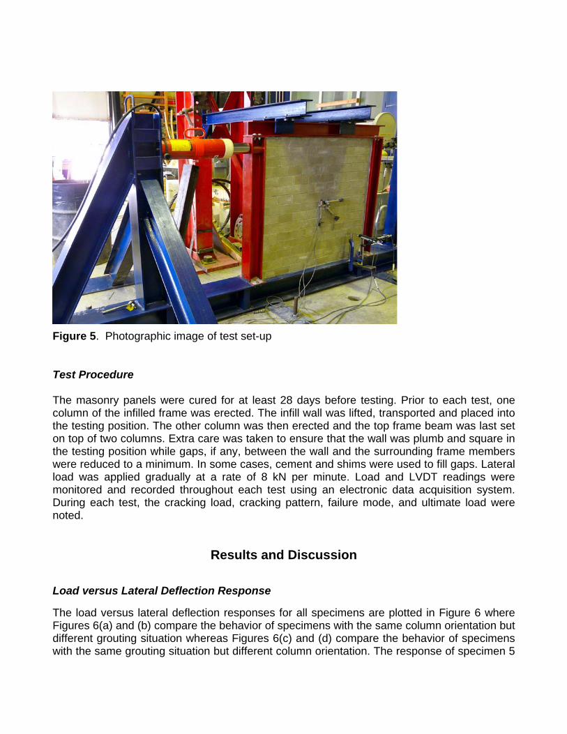
Figure 5. Photographic image of test set-up Test Procedure The masonry panels were cured for at least 28 days before testing. Prior to each test, one column of the infilled frame was erected. The infill wall was lifted, transported and placed into the testing position. The other column was then erected and the top frame beam was last set on top of two columns. Extra care was taken to ensure that the wall was plumb and square in the testing position while gaps, if any, between the wall and the surrounding frame members were reduced to a minimum. In some cases, cement and shims were used to fill gaps. Lateral load was applied gradually at a rate of 8 kN per minute. Load and LVDT readings were monitored and recorded throughout each test using an electronic data acquisition system. During each test, the cracking load, cracking pattern, failure mode, and ultimate load were noted.
Results and Discussion
Load versus Lateral Deflection Response
The load versus lateral deflection responses for all specimens are plotted in Figure 6 where Figures 6(a) and (b) compare the behavior of specimens with the same column orientation but different grouting situation whereas Figures 6(c) and (d) compare the behavior of specimens with the same grouting situation but different column orientation. The response of specimen 5
is included in Figures 6(a) and (b) for comparison. The lateral deflection was calculated as the difference between LVDT1 and LVDT2. It is clear from Figure 6 that infilled frames, in general, yielded much higher initial stiffness and ultimate strength than the bare frame. The bare frame was only tested for major axis column orientation. For both cases of column orientation as shown in Figures 6(a) and (b), the initial stiffness of infilled frames appears to be of same order of magnitude for fully grouted and partially grouted infills, indicating the extent of grouting has no significant effect on the initial stiffness. However, fully grouted infills resulted in higher ultimate strength and greater ductility than partially grouted infills. The comparison in Figures 6(c) and (d) indicate that for both fully and partially grouted infills, the strong axis column orientation showed greater initial stiffness but the weak axis column orientation seems to result in greater ductility. Overall, the curves suggest that the infilled frame with fully grouted infills and column oriented in strong axis bending showed the highest initial stiffness and the ultimate strength.
Figure 6. Load versus lateral deflection response.

Failure Modes
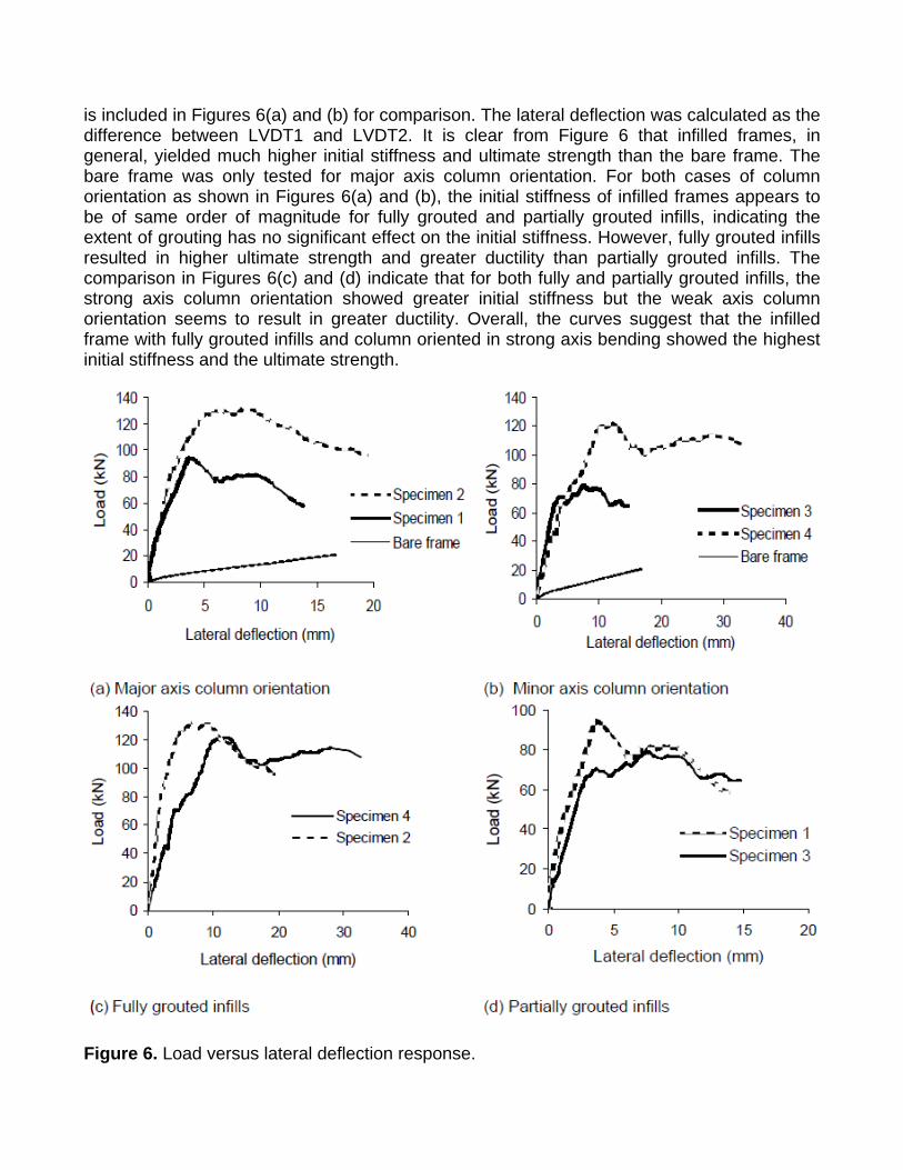
Corner crushing was observed to be the dominant failure mode for all infilled specimens. In most cases, there was a clear indication that a diagonal strut had developed in the infill wall. In the case of specimens 1, 2, and 3, hair line cracks began to occur in the loaded diagonal direction at about 70% of the ultimate load and developed into visible diagonal cracks prior to crushing of the loaded corner. However, no visible diagonal cracking was observed for specimen 4 before sudden failure of the bottom diagonal corner. When the column was oriented in weak axis bending, the infill was positioned between the flanges of the column section. It was difficult to totally eliminate the gap between the infill and the surrounding frame members despite effort. The visible gap was observed to be around 3 mm. The non-development of a diagonal strut was attributed to the presence of partial gapping between the masonry and the steel frame. No visible yielding of beams and columns was observed despite the large lateral deflection. However, upon removal of the infill, the frame did not return to its original position indicating some development of plastic deformation in the frame system. Figure 7 shows the typical failure modes for specimens.
a) Specimen 2 (b) Specimen 4 Figure 7. Failure patterns
Ultimate Strength
Table 2 summarizes the ultimate strengths of all specimens. Also listed is the principal strain at the ultimate load calculated using readings of LVDTs 4 to 6 mounted on the central region of the infill. Table shows that comparing with infilled frames with partially grouted walls, those with fully grouted walls attained higher ultimate strengths by about 40% for the case of strong column orientation and 54% for the case of weak column orientation. Given the same grouting situation, strong axis orientation of the steel columns resulted in an increase in the ultimate strength of the infilled frame system by about 6.5% for fully grouted infills and 17% for partially grouted infills. Variation of experimentally obtained principal strains is consistent with the ultimate load. The higher the load, the greater the strain at ultimate. The maximum principal strain was calculated to be 0.0028 for specimen 2. The LVDT readings for specimen 3 were not obtained due to a malfunction of LVDTs during testing. The very low strain calculated for specimen 4 further indicates that there might have been gapping between the infill and the surrounding frame thus inhibiting the development of a diagonal compression strut.
(a) Major axis column orientation (b) Fully grouted infills

Table 2. Summary of test results
Specimen Ultimate Strength
kN
Principal strain at ultimate
Stiffness kN/mm
Test CSA-S304 (2004)
El-Dakhakhni et al. (2003)
MSJC (proposed)
Tucker (2007)
1, PG 92.6 0.0019 27.9 76.0 47.3 30.0 29.0
2, FG 130.0 0.0028 31.0 100.0 60.3 35.5 34.0 3, PG 79.0 ---- 25.6 68.0 40.0 18.0 16.5 4, FG 122.0 0.0005 18.7 84.0 52.2 22.2 20.3
Bare Frame NA ---- 1.25 NA NA NA NA
Stiffness Comparison
In this section, the efficacy of design equations for stiffness as suggested in standards and by other researchers was evaluated by comparison with the experimentally obtained values. The various methods considered for comparison as presented in Table 2, include design equations suggested in CSA S304 (2004), proposed additions to MSJC (2008), and those proposed by El-Dakhakhni et al. (2003) and Tucker (2007). For experimentally determined values of stiffness, the initial stiffness was used and calculated based on the load versus lateral deflection curves. For all four methods being evaluated, the infill was replaced with a diagonal strut or three struts whose width/s was based on the proposed equations. A simple frame analysis was then carried out to determine the system stiffness. Table 2 shows that the equation suggested in CSA-S304 significantly overestimates the stiffness for all infilled specimens. In some case, this overestimation is as high as 4.5 times. The method by El-Dakhakhni et al. gives a stiffness estimate which is on average about twice the experimental result. The equations suggested by Tucker and MSJC provide stiffness values that are in good agreement and also compare relatively well with experimental results. Except for specimen 3, they provide stiffness values higher than experimental values by an average of 10%. This slight overestimation of the stiffness is a suitably conservative design approach. The initial stiffness of specimen 4 appears to be somewhat anomalous. Its abnormally low value is believed to be attributable to fabrication gaps between the infill and surrounding frame. Such gapping effects would be quite noticeable in the early stages of loading with a gradual diminution as loading increased beyond initial stages.
Conclusion
A test program was designed as a preliminary device to investigate the behavior and capacity of infilled frame systems under in-plane lateral loading. Parameters considered for investigation included the extent of grouting and frame-to-infill stiffness. Test results were presented and discussed and the efficacy of various design equations for stiffness of the infilled frames were evaluated. The following conclusions can be drawn from this study:
1. Fully grouted walls showed a significantly higher ultimate strength and greater ductility than partially grouted walls but the extent of grouting had no significant effect on the initial stiffness of the infilled frame systems.
2. For infilled frames, strong axis column orientation results in greater initial stiffness whereas weak axis column orientation results in greater overall ductility.
3. Corner crushing failure mode was present in all specimens with three showing visible diagonal cracking prior to failure.
4. Comparison of experimentally determined stiffness values with various design equations underscores the inconsistency existing among the methods. Two methods which provided reasonably good estimate of the test results were identified.
Acknowledgement
The authors wish to recognize the contribution of financial assistance by the Canadian Concrete Masonry Producers Association (CCMPA) and in kind assistance from the Masonry Industry Association of Atlantic Canada and Wildwood Masonry Ltd, Halifax, NS, Canada. .
References
Al-Chaar, G., Evaluating strength and stiffness of unreinforced masonry infill structures. Champaign, IL: US Army Corps of Engineers, Engineer Research and Development Center, Construction Engineering Research Laboratory, 2002. Canadian Standards Association, Design of masonry structures, CSA S304. Canadian Standards Association, Mississauga, Canada, 2004. Chiou, Y., "Experimental and Analytical Study of Masonry Infilled Frames," Journal of Structural Engineering (ASCE), 125(10), 1999, pp. 1109-1117. Dawe, J.L., C.K. Seah, “Behaviour of masonry infilled steel frames", Canadian Journal of Civil Engineering, 16(6), 1989, pp. 865-876. Drysdale, R.G., A. A. Hamid, Masonry Structures: Behaviour and Design. Canadian Edition, Canada Masonry Design Centre, Mississauga, Ontario, Canada, 2005. El-Dakhakhni, W.W., M. Elgaaly, A. A. Hamid , "Three-Strut Model for Concrete Masonry-Infilled Steel Frames," Journal of Structural Engineering (ASCE), 129(2), 2003, pp. 177-185. European Committee for Standardization, Eurocode 8: Design of Structures for Earthquake Resistance, British Standards Institution, England, 1998. Flanagan, R.D., R.M. Bennett, "In-Plane Analysis of Masonry Infill Materials", Practice Periodical on Structural Design and Construction, vol. 6, 2001, pp. 176-182. Flanagan, R.D., R.M. Bennett, "In-Plane Behavior of Structural Clay Tile Infilled Frames," Journal of Structural Engineering (ASCE), 125(6), 1999, pp. 590-599. Hatzinikolas, M., Y. Korany, Masonry Design: For Engineers and Architects, Canadian Masonry Publications, Canada, 2005. Hendry, A. W., Structural Brickwork, Wiley, USA, 1981.
Hendry, A. W., T. C. Liauw “Tests on steel frames with reinforced masonry infilling,” 1991, pp. 108-114. Holmes, M., ‘‘Steel frames with brickwork and concrete infilling,’’ Proceedings of Institution of Civil Engineers. vol. 19, 1961, pp. 473–478. Liauw, T. C., K. H. Kwan, “Nonlinear Behaviour of Non-Integral Infilled Frames,” Computers and Structures, 18(3), 1984, pp. 551-560. Mainstone, R. J. On the stiffnesses and strengths of infilled frames. Building Research Station, England, 1971. Maleki, M., A. A Hamid, A. A El-Damatty, R. G. Drysdale, “Behavior of partially grouted reinforced concrete masonry panels under in-plane diagonal loading,” Proceedings of the Tenth North American Masonry Conference, 2007, pp. 1039-1050. Masonry Standard Joint Committee (MSJC), Building Code Requirements for Masonry Structures, ACI S30/ASCE 5/TMS 402, American Concrete Institute, the American Society of Civil Engineers and The Masonry Society, USA, 2008. Mehrabi, A.B., P.B. Shing, M. P. Schuller, J. L. Noland, "Experimental Evaluation of Masonry-Infilled RC Frames," Journal of Structural Engineering (ASCE), 122(3), 1996, pp. 228-237. Moghaddam, H., P. Dowling, “Earthquake Resistant Design of Brick Infilled Frames,” Proceedings of the Eighth International Brick and Block Masonry Conference, 1988, pp. 774-784. Mosalam, K.M., R.N. White, P. Gergely, "Static Response of Infilled Frames Using Quasi-Static Experimentation," Journal of Structural Engineering (ASCE), 123(11), 1997, pp. 1462-1469. Papia, M., L. Cavaleri, M. Fossetti, "Infilled frames: developments in the evaluation of the stiffening effect of infills", Structural Engineering and Mechanics, vol. 16, 2003, pp. 675-694. Paulay, T., M. J. N. Priestley, Seismic Design of Reinforced Concrete and Masonry Buildings, Wiley, New York, USA, 1992. Polyakov, S. V., ‘‘Masonry in framed buildings,’’ Godsudarstvenoe Isdatel stvo Literatury Po Stroidal stvui Architecture, Russia, 1956. Riddington, J. R., “The influence of initial gaps on infilled frame behaviour”. Proceedings of the Institution of Civil Engineers, 77(2), 1984, pp. 295–310. Saneinejad, A., B. Hobbs, "Inelastic Design of Infilled Frames", Journal of Structural Engineering (ASCE), 121(4), 1995, pp. 634-650. Seah, C. K. “A universal approach for the analysis and design of masonry infilled frame structures,” Ph.D. thesis. Dept. of Civil Engineering, University of New Brunswick, Canada, 1998. Shing, P. B., A. B. Mehrabi, “Behaviour and analysis of masonry-infilled frames,” Progress in Structural Engineering and Materials. vol. 4, 2002, pp. 320-331. Stafford-Smith, B., C. Carter, “A method of analysis for infilled frames,” Proceedings of the Institution of Civil Engineers, vol. 44,1969, pp. 31-48.Standard Association of New Zealand, Code of Practice for the Design of Masonry Structures. NZS 4230: Part 1, Wellington, 1990. Tucker, C. J. “Predicting the In-Plane Capacity of Masonry Infilled Frames,” Ph.D. Thesis, Tennessee Technological University, USA, 2007. Wood, R. H. “Plasticity, composite action and collapse design of unreinforced shear wall panels in frames,” Proceedings of Institution of Civil Engineers. Part 2, 1978. vol. 65, June, 1978, pp. 381-411.