Experimental Analysis and Modeling of Four Stroke Engine ...
13
International Journal of Scientific & Engineering Research, Volume 4, Issue 12, December-2013 ISSN 2229-5518 IJSER © 2013 http://www.ijser.org Experimental Analysis and Modeling of Four Stroke Engine with Nanosized Copper Coated Catalytic Converter Mukesh Thakur, Dr. N.K. Saikhedkar Abstract - This paper basically deals with behavioural modeling and analysis of a four stroke engine including a prepared model of catalytic converter. The modeling can be very helpful to analyse the mathematical nature of the process of exhaust emission reduction through catalytic converter and analysis gives pollutant concentration. The basic idea of behavioral modeling starts from analyzing the practical behavior of four stroke engine and designed catalytic convertor and then approximating obtained behavior in terms of mathematical equations. These obtained equations actually represent behavior of concern system. AVL-422 gas analyzer was used for measurement and comparison for CO and unburnt hydrocarbon in the exhaust of the engine at various speeds and loads. In the present work, some modifications have been designed to provide more time for its oxidation and thereby to reduce harmful emissions. Index Terms – Modeling, nano-particles, pollution control, catalytic converter —————————— —————————— 1 INTRODUCTION HE environmental concern originated by automobile sources is due to the fact that the majority of engines em- ploy combustion of fuels derived from crude oil as a source of energy. Burning of hydrocarbon (HC) ideally leads to the formation of water and carbon dioxide; however, due to improper combustion control and the high temperatures reached in the combustion chamber, the exhaust contains sig- nificant amounts of pollutants which need to be transformed into harmless compounds. In this paper, the control strategies and achievements in automotive pollution control using nano- particles are discussed. Nanotechnology has assumed a very important role today mainly because of its utility and applica- tion area. No field is untouched by nanotechnology [2]. The increasing demand for a quality poduct in the market has forced the industries to move from macro to micro to nano level. Every aspect of the product is analyzed in detail [3]. In the automotive industry, nanotechnology applications are manifold. They reach from power train, light-weight construc- tion, energy conversion, pollution sensing and reduction, inte- rior cooling, wear reduction, driving dynamics, surveillance control, up to recycle potential and much more [4]. Additionally, visions of ‘‘nano in cars’’ reach from contribu- tions for carbon di-oxide free engines, safe driving, quiet cars, self-healing body and windscreens, up to a mood-depending choice of color and a self-forming car body. All this will meet the present society trends and customer demands for im- proved ecology, safety and comfort, often summarized by the term sustainability. Due to their large number, the automo- biles are the major source of pollution. Various improvements in the engine design have been made to prevent the exhaust emission level but they prove to be insufficient. So, an alterna- tive and effective approach is highly recommended [5-6]. Alt- hough a two stroke spark ignition engine is compact and light weight as compared to a four stroke engine but it produces a higher level of exhaust emissions than a four stroke spark igni- tion engine. Instead of chnging the complete design of the en- gine, the exhaust pipe can be connected to a nano-coated cata- lytic converter which will reduce the concenteration of exhaust emissions being emitted to the atmosphere. The properties and structure of nanomaterials are very effective in reducing the exhaust emissions primarily due to their small size and high reactivity [7-8]. Thakur and Saikhedkar presented a comprehensive review on the recent trends in application of nano-technology in automo- tive pollution control was covered. First, the essential aspects of environmental problems due to automotive industry were discussed and then the application of nanotechnology towards the prevention and control of these problems were suggested in detail [9]. The utility of the nano-particles towards automo- bile pollution control was explained in detail. The nano- particle coating on the catalytic converter of automobiles can be very helpful in the reduction of pollutant concentration and thus reduce the pollution level in atmosphere [10]. Amongst main metals like Au, Ag, Pd, Pt, towards which nanotechnol- ogy research is directed, copper and copper based compounds are the most important. The metallic Copper plays a signifi- cant role in modern electronics circuits due to its excellent electrical conductivity and low cost nanoparticles [11]. Thakur and Saikhedkar analysed the post pollution control method in two-wheeler automobiles using nano-particle as a catalyst was proposed. A study on nano-particle reveals that the ratio of surface area of nano-particle to the volume of the nano- particle is inversely proportional to the radius of the nano- particle. So, on decreasing the radius, this ratio is increased leading to an increased rate of reaction and the concentration of the pollutants is decreased [12]. It involves the use of cop- per nano-particle which is cheaper than the platinum, palladi- um and rhodium nano-particles used in automobiles [13]. A microprocessor based analyzer was used for measurement of CO and HC emissions [14]. To control the exhaust emissions from two stroke single cylinder spark ignition petrol engine having copper nano-particles coated on copper sieve as cata- lytic converter was used by Thakur and Saikhedkar. AVL-422 T 1329 IJSER
Transcript of Experimental Analysis and Modeling of Four Stroke Engine ...
International Journal of Scientific & Engineering Research, Volume 4, Issue 12, December-2013 ISSN 2229-5518
IJSER © 2013
http://www.ijser.org
Experimental Analysis and Modeling of Four Stroke Engine with Nanosized Copper Coated
Catalytic Converter Mukesh Thakur, Dr. N.K. Saikhedkar
Abstract - This paper basically deals with behavioural modeling and analysis of a four stroke engine including a prepared model of
catalytic converter. The modeling can be very helpful to analyse the mathematical nature of the process of exhaust emission reduction
through catalytic converter and analysis gives pollutant concentration. The basic idea of behavioral modeling starts from analyzing the
practical behavior of four stroke engine and designed catalytic convertor and then approximating obtained behavior in terms of
mathematical equations. These obtained equations actually represent behavior of concern system. AVL-422 gas analyzer was used for
measurement and comparison for CO and unburnt hydrocarbon in the exhaust of the engine at various speeds and loads. In the present
work, some modifications have been designed to provide more time for its oxidation and thereby to reduce harmful emissions.
Index Terms – Modeling, nano-particles, pollution control, catalytic converter
—————————— ——————————
1 INTRODUCTION
HE environmental concern originated by automobile sources is due to the fact that the majority of engines em-ploy combustion of fuels derived from crude oil as a
source of energy. Burning of hydrocarbon (HC) ideally leads to the formation of water and carbon dioxide; however, due to improper combustion control and the high temperatures reached in the combustion chamber, the exhaust contains sig-nificant amounts of pollutants which need to be transformed into harmless compounds. In this paper, the control strategies and achievements in automotive pollution control using nano-particles are discussed. Nanotechnology has assumed a very important role today mainly because of its utility and applica-tion area. No field is untouched by nanotechnology [2]. The increasing demand for a quality poduct in the market has forced the industries to move from macro to micro to nano level. Every aspect of the product is analyzed in detail [3]. In the automotive industry, nanotechnology applications are manifold. They reach from power train, light-weight construc-tion, energy conversion, pollution sensing and reduction, inte-rior cooling, wear reduction, driving dynamics, surveillance control, up to recycle potential and much more [4]. Additionally, visions of ‘‘nano in cars’’ reach from contribu-tions for carbon di-oxide free engines, safe driving, quiet cars, self-healing body and windscreens, up to a mood-depending choice of color and a self-forming car body. All this will meet the present society trends and customer demands for im-proved ecology, safety and comfort, often summarized by the term sustainability. Due to their large number, the automo-biles are the major source of pollution. Various improvements in the engine design have been made to prevent the exhaust emission level but they prove to be insufficient. So, an alterna-tive and effective approach is highly recommended [5-6]. Alt-hough a two stroke spark ignition engine is compact and light weight as compared to a four stroke engine but it produces a higher level of exhaust emissions than a four stroke spark igni-tion engine. Instead of chnging the complete design of the en-
gine, the exhaust pipe can be connected to a nano-coated cata-lytic converter which will reduce the concenteration of exhaust emissions being emitted to the atmosphere. The properties and structure of nanomaterials are very effective in reducing the exhaust emissions primarily due to their small size and high reactivity [7-8]. Thakur and Saikhedkar presented a comprehensive review on the recent trends in application of nano-technology in automo-tive pollution control was covered. First, the essential aspects of environmental problems due to automotive industry were discussed and then the application of nanotechnology towards the prevention and control of these problems were suggested in detail [9]. The utility of the nano-particles towards automo-bile pollution control was explained in detail. The nano-particle coating on the catalytic converter of automobiles can be very helpful in the reduction of pollutant concentration and thus reduce the pollution level in atmosphere [10]. Amongst main metals like Au, Ag, Pd, Pt, towards which nanotechnol-ogy research is directed, copper and copper based compounds are the most important. The metallic Copper plays a signifi-cant role in modern electronics circuits due to its excellent electrical conductivity and low cost nanoparticles [11]. Thakur and Saikhedkar analysed the post pollution control method in two-wheeler automobiles using nano-particle as a catalyst was proposed. A study on nano-particle reveals that the ratio of surface area of nano-particle to the volume of the nano-particle is inversely proportional to the radius of the nano-particle. So, on decreasing the radius, this ratio is increased leading to an increased rate of reaction and the concentration of the pollutants is decreased [12]. It involves the use of cop-per nano-particle which is cheaper than the platinum, palladi-um and rhodium nano-particles used in automobiles [13]. A microprocessor based analyzer was used for measurement of CO and HC emissions [14]. To control the exhaust emissions from two stroke single cylinder spark ignition petrol engine having copper nano-particles coated on copper sieve as cata-lytic converter was used by Thakur and Saikhedkar. AVL-422
T
1329
IJSER

International Journal of Scientific & Engineering Research Volume 4, Issue 12, December-2013 ISSN 2229-5518
IJSER © 2013
http://www.ijser.org
Gas analyzer was used for the measurement and comparison for CO and unburned hydrocarbon in the exhaust of the en-gine at various speeds and loads [15]. The conversion efficien-cy of a catalytic converter mounted on a vehicle with spark ignition engine was evaluated under steady operating condi-tions [16]. Three way converters have been compared to un-derstand the influence of the substrate on the exhaust gas con-versions for many operating conditions of vehicle (Silva and Costa, 2008). Various tests conducted on four stroke engine reveal that the copper coated engine showed a better perfor-mance than a normal engine [17]. On using copper powder, the catalytic efficiency was found to increase as the size of the powder decreased [18]. A nano catalytic converter was de-signed and manufactured to reduce the pollution in the envi-ronment [19]. Nano-coatings can be used to reduce surface roughness of engine components and to act as protective coat-ing against wear of components [20]. Experiments were con-ducted to improve the engine performance and reduce the emissions of HC and CO from vehicle. Thakur and Saikhedkar made some alterations and modifications so as to increase the retention period of exhaust gases to provide more time for its oxidation and thereby to reduce harmful emissions. In the present work, practical behavior of four stroke engine and designed catalytic convertor was analysed and then approxi-mation of obtained behavior in terms of mathematical equa-tions was done before simulating it [21]. Microchannels in stainless steel were fabricated by using solutions of various concentrations of FeCl , HCl and HNO in water as etchants. This study shows that for obtaining smooth uniform channels on stainless steel substrates, an etchant consisting of FeCl , HCl and HNO is necessary. An increase in the concentration of HCl in the etchant increases the etch rate as well as the etch factor but adversely affects the roughness. Addition of HNO is necessary to obtain smooth uniform channels. The depth and etch factor are significantly affected by the composition of etchant, operating temperature and initial width of opening. In the range of operating conditions studied, an etchant con-taining 10 wt% FeCl, 10 wt% HCl and 5 wt% HNO at 40 °C and an initial width of 190 μm gave the best results. With this etchant, the channels were smooth and uniform without any cavities on the edges of the channels. Initial width also plays a vital role in obtaining the final desired depth and etch factor [22]. Thakur and Saikhedkar dealt with the behavioral model-ing and simulation of two stroke engine with developed cata-lytic convertor. The basic idea of behavioral modeling starts from analyzing the practical behavior of two stroke engine and designed catalytic convertor, and then approximating obtained behavior in terms of mathematical equations. These obtained equations actually represent behavior of concern sys-
tem. Once mathematical equations are obtained, next stage is to implementation of these equations in Simulink platform. The last process is the validation check by the simulation of developed model [23]. To control the exhaust emissions from two stroke spark ignition engine, copper nano-particles coated on wire mesh at the junction of improved design as catalytic converter, AVL-422 gas analyzer was used for measurement and comparision for CO and unburnt hydrocarbon in the ex-haust of the engine at various speeds and loads. In the present work, an improved design is proposed which is more suitable for implementation along with improved performance and efficiency in reducing the exhaust emissions from two stroke spark ignition engine. [24].
2 PROCEDURE
2.1 Copper Nano-particle coating (Drop Casting Method)
Drop casting method was used to coat copper nano-particle. Since, the method is very simple and no waste is generated. Cut section model of porous assembly as shown in figure 7 was coated with copper nano-particle in the following man-ner: 1. Etchening of assembly: The assembly was etched by using a method suggested before [25]. In this method, a mixture of 10 wt % FeCl3, 10 wt % HCl and 5 wt % HNO3 was used as etchant. The etchant was spread over the assembly surface and kept at stand for 15 minutes and then washed copiously with hot distilled water. 2. Drop casting of copper nanoparticles: Copper nanoparticles were coated on roughened surface using drop casting method. Similar method was adopted before for deposition of polymer nanofilm and semiconductor thin film [26]. With certain modi-fications in these literatures, it was incorporated in our coating method. In this method, copper nanoparticles were suspended into an Ethylene glycol and ultrasonically blended for two hours to get a uniform suspension. Then, this suspension was dropped uniformly over porous assembly surface and dried in an oven at 200°C for two hours. After oven drying of first layer, anoth-er layer of copper nanoparticles was coated by repeating the dropping procedure and it was dried again at 200°C for two hours. As obtained copper nanoparticle coated porous assem-bly was then subjected to heat treatment. 3. Heat treatment of copper nanoparticle coated porous as-sembly: - The heat treatment was carried out by heating the copper nanoparticle coated layer at 800°C for 10 minutes and maintaining inert atmosphere in a furnace. The inert atmos-phere was maintained by purging 99.9 % pure nitrogen gas before and during entire heat treatment process. As obtained copper nanoparticles coated plate were then washed with dis-tilled water to remove any loose particle and impurity.
————————————————
Mukesh Thakur is currently working as Reader in Rungta College of Engineer-ing and Technology, Raipur, Chhattisgarh, India. PH-09826457134. E-mail: [email protected]
Dr. N.K. Saikhedkar is currently working as Director and Professor in RIT, Raipur, Chhattisgarh, PH-09826156500. E-mail: [email protected]
1330
IJSER
International Journal of Scientific & Engineering Research Volume 4, Issue 12, December-2013 ISSN 2229-5518
IJSER © 2013
http://www.ijser.org
This section basically deals with the behavioral modeling and simulation of four stroke engine with developed catalytic con-vertor. The basic idea of behavioral modeling starts from ana-lyzing the practical behavior of four stroke engine and de-signed catalytic convertor and then approximating obtained behavior in terms of mathematical equations. These obtained equations actually represent behavior of concern system. Once mathematical equations are obtained, next stage is to imple-mentation of these equations in Simulink platform. The last process is the validation check by the simulation of developed model.
2.2 Behavioral Modeling of Four Stroke Engine
This subsection presents the complete behavioral modeling of four stroke engine. The engine specifications are as follows: Four stroke engine (4S) RPM: 3 HP FUEL: PETROL NUMBER OF CYLINDERS: SINGLE BORE: 70 mm STROKE LENGTH: 70 mm These three important parameters are basically independent variable for modeling, and it is difficult to address simultane-ously. However among these three on can be assume constant, so for modeling of four stroke in this paper horse power of engine is taken as constant, this leads the reduction of one in-dependent variable from the list. Now following steps provide complete idea of behavioral modeling of four stroke engine. Step 1. Define the behavior of four stroke engine in terms of input and output variables. For modeling, the input variables are:
i. Speed of engine in RPM. ii. Applicable load during running condition.
Similarly the output variables for our work are i. CO in percentage.
ii. HC in PPM.
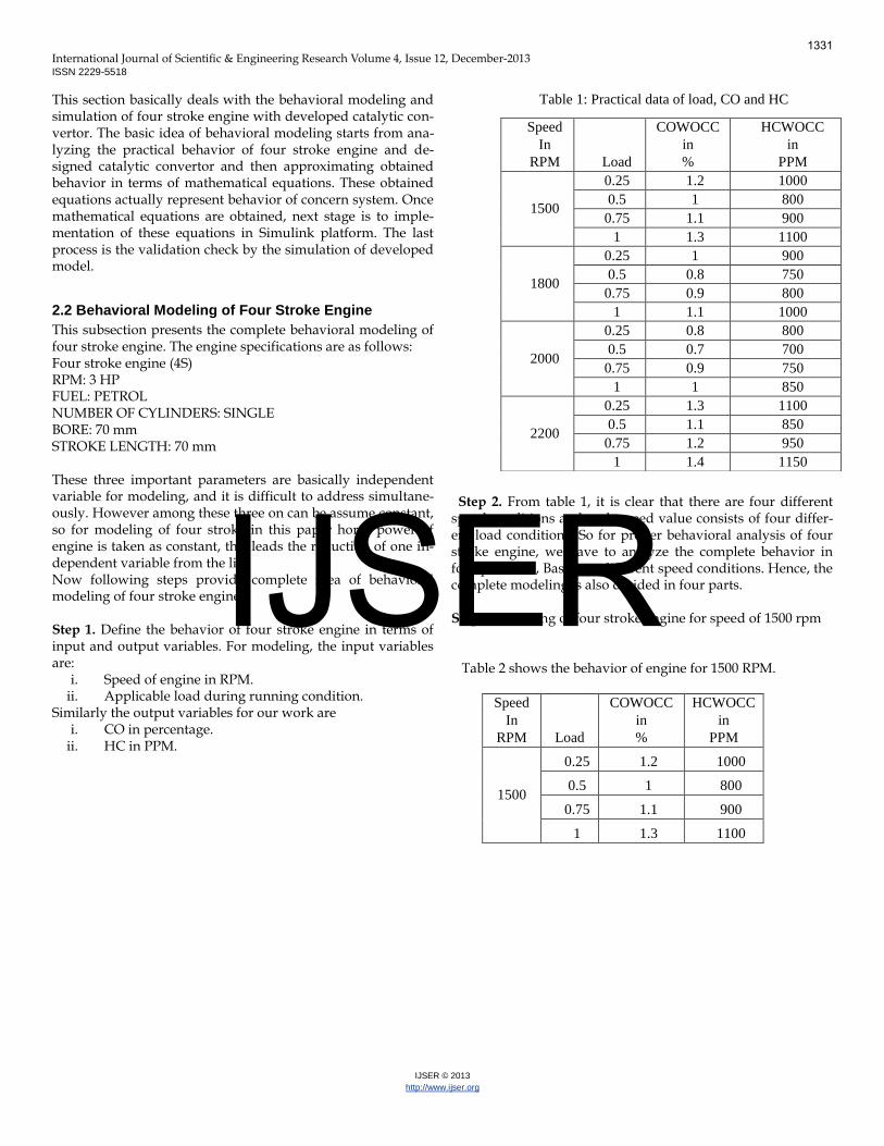
Table 1: Practical data of load, CO and HC
Step 2. From table 1, it is clear that there are four different speed conditions and each speed value consists of four differ-ent load conditions. So for proper behavioral analysis of four stroke engine, we have to analyze the complete behavior in four parts, i.e., Based on different speed conditions. Hence, the complete modeling is also divided in four parts. Step 3. Modeling of four stroke engine for speed of 1500 rpm Table 2 shows the behavior of engine for 1500 RPM.
Speed
In
RPM Load
COWOCC
in
%
HCWOCC
in
PPM
1500
0.25 1.2 1000
0.5 1 800
0.75 1.1 900
1 1.3 1100
Speed
In
RPM Load
COWOCC
in
%
HCWOCC
in
PPM
1500
0.25 1.2 1000
0.5 1 800
0.75 1.1 900
1 1.3 1100
1800
0.25 1 900
0.5 0.8 750
0.75 0.9 800
1 1.1 1000
2000
0.25 0.8 800
0.5 0.7 700
0.75 0.9 750
1 1 850
2200
0.25 1.3 1100
0.5 1.1 850
0.75 1.2 950
1 1.4 1150
1331
IJSER
International Journal of Scientific & Engineering Research Volume 4, Issue 12, December-2013 ISSN 2229-5518
IJSER © 2013
http://www.ijser.org
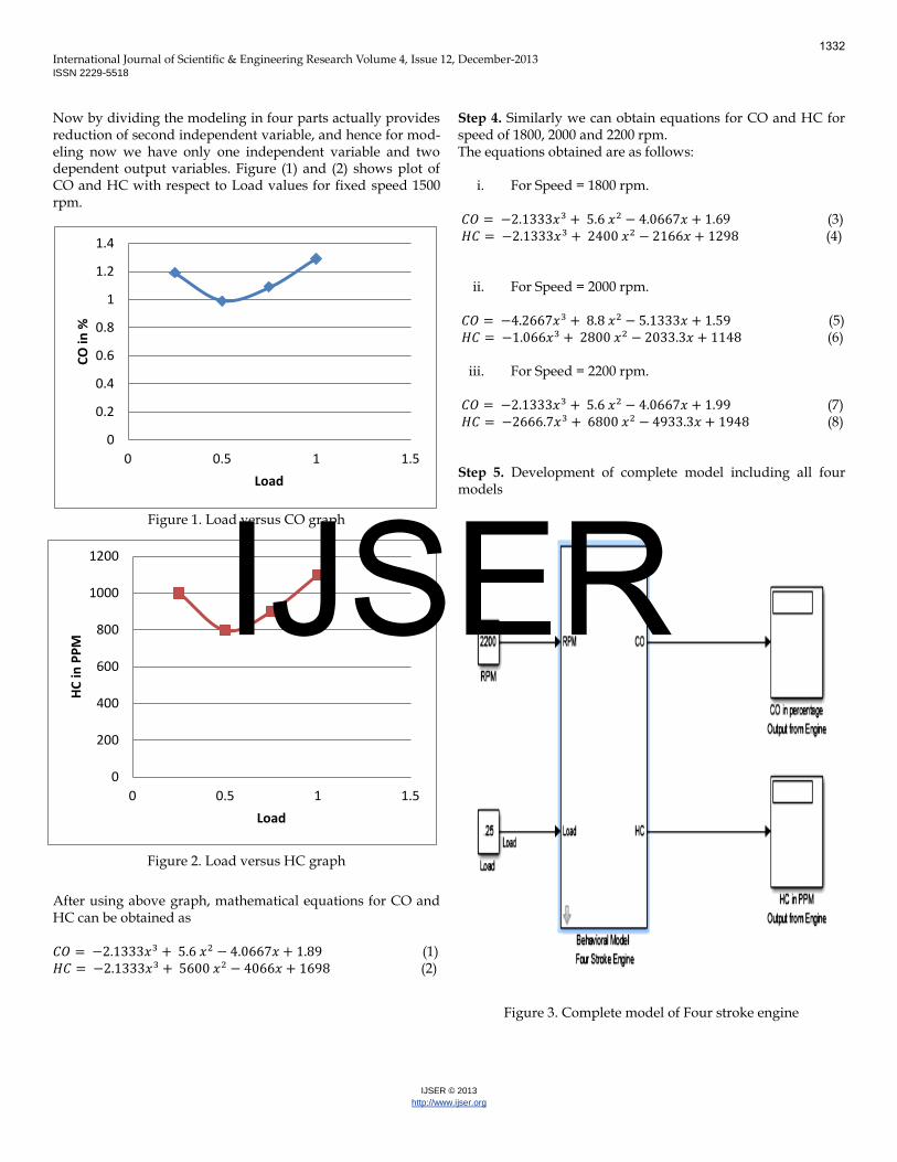
Now by dividing the modeling in four parts actually provides reduction of second independent variable, and hence for mod-eling now we have only one independent variable and two dependent output variables. Figure (1) and (2) shows plot of CO and HC with respect to Load values for fixed speed 1500 rpm.
Figure 1. Load versus CO graph
Figure 2. Load versus HC graph
After using above graph, mathematical equations for CO and HC can be obtained as 𝐶𝑂 = −2.1333𝑥 + 5.6 𝑥 − 4.0667𝑥 + 1.89 (1) 𝐻𝐶 = −2.1333𝑥 + 5600 𝑥 − 4066𝑥 + 1698 (2)
Step 4. Similarly we can obtain equations for CO and HC for speed of 1800, 2000 and 2200 rpm. The equations obtained are as follows:
i. For Speed = 1800 rpm. 𝐶𝑂 = −2.1333𝑥 + 5.6 𝑥 − 4.0667𝑥 + 1.69 (3) 𝐻𝐶 = −2.1333𝑥 + 2400 𝑥 − 2166𝑥 + 1298 (4)
ii. For Speed = 2000 rpm. 𝐶𝑂 = −4.2667𝑥 + 8.8 𝑥 − 5.1333𝑥 + 1.59 (5) 𝐻𝐶 = −1.066𝑥 + 2800 𝑥 − 2033.3𝑥 + 1148 (6)
iii. For Speed = 2200 rpm. 𝐶𝑂 = −2.1333𝑥 + 5.6 𝑥 − 4.0667𝑥 + 1.99 (7) 𝐻𝐶 = −2666.7𝑥 + 6800 𝑥 − 4933.3𝑥 + 1948 (8) Step 5. Development of complete model including all four models
Figure 3. Complete model of Four stroke engine
0
0.2
0.4
0.6
0.8
1
1.2
1.4
0 0.5 1 1.5
CO
in %
Load
0
200
400
600
800
1000
1200
0 0.5 1 1.5
HC
in P
PM
Load
1332
IJSER
International Journal of Scientific & Engineering Research Volume 4, Issue 12, December-2013 ISSN 2229-5518
IJSER © 2013
http://www.ijser.org
2.3 Behavioral Modeling of Catalytic Converter
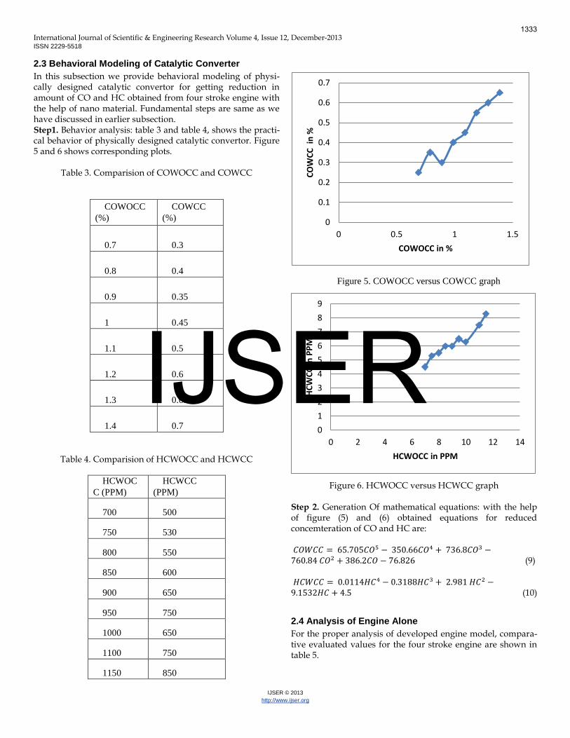
In this subsection we provide behavioral modeling of physi-cally designed catalytic convertor for getting reduction in amount of CO and HC obtained from four stroke engine with the help of nano material. Fundamental steps are same as we have discussed in earlier subsection. Step1. Behavior analysis: table 3 and table 4, shows the practi-cal behavior of physically designed catalytic convertor. Figure 5 and 6 shows corresponding plots.
Table 3. Comparision of COWOCC and COWCC
COWOCC
(%)
COWCC
(%)
0.7 0.3
0.8 0.4
0.9 0.35
1 0.45
1.1 0.5
1.2 0.6
1.3 0.65
1.4 0.7
Table 4. Comparision of HCWOCC and HCWCC
HCWOC
C (PPM)
HCWCC
(PPM)
700 500
750 530
800 550
850 600
900 650
950 750
1000 650
1100 750
1150 850
Figure 5. COWOCC versus COWCC graph
Figure 6. HCWOCC versus HCWCC graph Step 2. Generation Of mathematical equations: with the help of figure (5) and (6) obtained equations for reduced concemteration of CO and HC are: 𝐶𝑂𝑊𝐶𝐶 = 65.705𝐶𝑂 − 350.66𝐶𝑂 + 736.8𝐶𝑂 −760.84 𝐶𝑂 + 386.2𝐶𝑂 − 76.826 (9)
𝐻𝐶𝑊𝐶𝐶 = 0.0114𝐻𝐶 − 0.3188𝐻𝐶 + 2.981 𝐻𝐶 −9.1532𝐻𝐶 + 4.5 (10)
2.4 Analysis of Engine Alone
For the proper analysis of developed engine model, compara-tive evaluated values for the four stroke engine are shown in table 5.
0
0.1
0.2
0.3
0.4
0.5
0.6
0.7
0 0.5 1 1.5
CO
WC
C i
n %
COWOCC in %
0
1
2
3
4
5
6
7
8
9
0 2 4 6 8 10 12 14
HC
WC
C in
PP
M
HCWOCC in PPM
1333
IJSER

International Journal of Scientific & Engineering Research Volume 4, Issue 12, December-2013 ISSN 2229-5518
IJSER © 2013
http://www.ijser.org
Speed
In RPM
Load CO in % HC in PPM
Practical Simulation Percentage
Error in %
Practical Simulation Percentage
Error in %
1500
0.25 1.2 1.19 0.83 1000 998 0.20
0.5 1 0.99 1.00 800 798 0.25
0.75 1.1 1.09 0.91 900 898 0.22
1 1.3 1.29 0.77 1100 1098 0.18
1800
0.25 1 0.99 1.00 900 898 0.22
0.5 0.8 0.79 1.25 750 748 0.27
0.75 0.9 0.89 1.11 800 798 0.25
1 1.1 1.09 0.91 1000 998 0.20
2000
0.25 0.8 0.79 1.25 800 798 0.25
0.5 0.7 0.69 1.43 700 698 0.29
0.75 0.9 0.89 1.11 750 748 0.27
1 1 0.99 1.00 850 848 0.24
2200
0.25 1.3 1.29 0.77 1100 1098 0.18
0.5 1.1 1.09 0.91 850 848 0.24
0.75 1.2 1.19 0.83 950 948 0.21
1 1.4 1.39 0.71 1150 1148 0.17
Table 5. Comparitive evaluated values
1334
IJSER

International Journal of Scientific & Engineering Research Volume 4, Issue 12, December-2013 ISSN 2229-5518
IJSER © 2013
http://www.ijser.org
From table 5, it is clearly observable, that the maximum per-centage error obtained for CO is 1.43% and for HC is 0.29%, which are very small and hence the developed behavioral simulation model of four stroke engine is the exact replica of practical four stroke engine considered for this work.
2.5 Analysis of Complete Engine with Catalytic Convertor
For the proper analysis of developed Catalytic Convertor model, comparative evaluated values for the Catalytic Conver-tor are shown in table 6.
Speed
In RPM
Load COWCC in % HCWCC in PPM
Practical Simulation Percentage
Error in %
Practical Simulation Percentage Er-
ror in %
1500
0.25 0.6 0.56
6.45
700 639.8
8.60
0.5 0.42 0.38
9.76
600 554.64
7.56
0.75 0.52 0.48
8.52
650 599.67
7.74
1 0.62 0.60
2.90
750 713.67
4.84
1800
0.25 0.41 0.38
7.56
600 599.67
0.06
0.5 0.4 0.39
2.50
550 512.569
6.81
0.75 0.48 0.44
8.33
580 554.64
4.37
1 0.52 0.49
5.77
630 629.8
0.03
2000
0.25 0.4 0.38
5.00
550 549.64
0.07
0.5 0.3 0.27
8.53
500 453.43
9.31
0.75 0.35 0.33
5.46
530 512.569
3.29
1 0.45 0.41
8.89
600 582.239
2.96
2200
0.25 0.65 0.60
7.38
800 726.67
9.17
0.5 0.5 0.48
4.86
650 592.239
8.89
0.75 0.6 0.56
6.45
715 646.949
9.52
1 0.7 0.67
4.49
850 804.689
5.33
Table 6. Comparision performance table
From table 6, it is clearly observable, that the maximum per-centage error obtained for CO is 9.76% and for HC is 9.52%, which are very small and hence the developed behavioral
simulation model of complete engine with catalytic convertor is the exact replica of practical complete four stroke engine with catalytic convertor considered for this work.
1335
IJSER

International Journal of Scientific & Engineering Research Volume 4, Issue 12, December-2013 ISSN 2229-5518
IJSER © 2013
http://www.ijser.org
3 RESULTS AND DISCUSSION
The majority of the environmental pollution is due to the two-wheeler automobiles due to their large number. Many envi-ronmentalists are interested in using precious metal nanopar-ticles as exhaust filters, both for vehicles and for power plants. In vehicles, particularly those that are diesel-powered, the na-noparticles have been shown to be effective in oxidizing harm-ful hydrocarbon compounds that are released in their exhaust, thereby reducing their negative impact on the atmosphere. Platinum, gold and palladium are the most commonly used when it comes to diesel filtering. There are two methods of control of pollution namely, pre-pollution control and post pollution control. This paper is based on the post pollution control method in two-wheeler automobiles using nano-particle as a catalyst. A study on nano-particle reveals that the ratio of surface area of nano-particle to the volume of the nano-particle is inversely proportional to the radius of the nano-particle. So, on decreasing the radius, this ratio is in-creased leading to an increased rate of reaction and the con-centration of the pollutants is decreased.
4 CONCLUSION
The proposed method is very effective in the prevention of environmental pollution contributed from two-wheeler auto-mobiles. It involves the use of copper nano-particle which is cheaper than the platinum, palladium and rhodium nano-particles used in automobiles. To achieve this objective, an innovative design of catalytic converter for two-wheeler au-tomobiles is proposed using nano-particle as a catalyst. The converter uses two different types of catalyst, reduction and oxidation catalyst. In the present work, the experimentation has been done for a four stroke engine with and without cata-lytic converter and the results clearly reveals that the emission level can be reduced by the use of catalytic converter. This paper basically deals with modeling of a complete system which includes a four stroke engine including a prepared model of catalytic converter. The modeling can be very helpful to predict the mathematical nature of the process of exhaust emission.
ACKNOWLEDGMENT
The authors wish to thank Rungta College of Engineering and Technology, Raipur for their support.
REFERENCES
[1] Gilmour P S, Ziesenis A, Morrison E R, Vickers M A, Drost E M, Ford
I, 2004, “Pulmonary and systemic effects of short term inhalation ex-
posure to ultrafine carbon black particles”, Toxicological Applica-
tions Pharmacology, 195, pp. 35–44.
[2] M. V., Twigg, 2006, “Roles of catalytic oxidation in control of vehicle
exhaust emissions”, Catalysis Today, 117(4), pp. 407-418.
[3] Kishore K., Krishna M.V.S., 2008, “Performance of Copper Coated
Spark Ignition Engine with Methanol Bended Gasoline with Catalytic
Converter”, Journal of Scientific and Industrial Research, 67, pp.543-
548.
[4] Thakur Mukesh, Saikhedkar, N.K., 2012, “Recent trends in applica-
tion of nano-technology to automotive pollution control”, Interna-
tional Science Congress.
[5] Thakur Mukesh, Saikhedkar, N.K., October 2012, “Role of metal
nano-particles for automobile pollution control”, International Jour-
nal of Engineering Research and Applications, 2(5), pp. 1947-1952.
[6] Feldheim D. L., Foss C. A., 2004, “Metal Nanoparticles: Synthesis,
Characterization and Applications”, Appl. Phys. A Mater. Sci. Pro-
cess. 78, pp.73.
[7] Schaper A. K, Hou H., Greiner A.,Schneider R., Philips F., 2004,
“One Pot Synthesis of Copper Nanoparticles at Room Temperature
and its Catalytic Activity”, Appl. Phys. A Mater. Sci. Process. , 78,
pp.73.
[8] Pergolese B, Muniz-Miranda M. , Bigotto A., 2004, “SERS: a versatile
tool in Chemical and Biochemical diagnostics”, J. Phys. Chem.,110
(92), pp.41.
[9] Thakur Mukesh, Saikhedkar, N.K., Sharma, Shilpa, 2013, “Rapid
Control of Exhaust Emissions and Enhancement of Retention Time in
the Catalytic Converter Using Nanosized Copper Metal Spray for
Spark Ignition Engine”, Priyanka Research Journal, 3(1), pp. 1-10.
[10] Recent trends in application of nano-technology to automotive pollu-
tion control”, International Science Congress.
[11] Flytzanis C. J., 2005, “Nonlinear optics in Mesoscopic Composite
materials”, Physics B, 38 , pp.661.
[12] Thakur Mukesh, Saikhedkar, N.K., October 2012, “Atomic Activity of
Nano-particles for vehicular pollution control”, Abhinav Journal,
1(11), pp. 32-38.
[13] M. SAMIM, N. K. KAUSHIK, A. MAITRA, 2007, “Effect of Size of
Copper Nanoparticles on its Catalytic Behaviour in Ullman Reac-
tion”, Bull. Mater. Sci., 30 (5), pp.535-540.
[14] Huynh W., U, Dittmer J., Libby William C., Whiting, G. L , Alvisatos
A .Paul , 2003, “Shape control and applications of nanocrystals”,
Adv. Funct. Mater., 13, pp.73. [15] Thakur Mukesh, Saikhedkar, N.K., 2013, “Rapid Control of Exhaust
Emissions and Enhancement of Retention Time for Four Stroke En-gine Using Nano-sized Copper Metal Spray”, International Journal of Science, Engineering and Research, 4(1).
[16] Sharma R. K., Sharma P., Maitra A. N., 2003, “Metal nanoparticles
with high catalytic activity in degradation of methyl orange: An elec-
tron relay effect”, J. Colloid. Sci. 265, pp.134.
[17] Feldheim D. L., Foss C. A., 2004, “Metal Nanoparticles: Synthesis,
Characterization and Applications”, Appl. Phys. A Mater. Sci. Pro-
cess. 78, pp.73.
[18] Schaper A. K, Hou H., Greiner A.,Schneider R., Philips F., 2004,
“One Pot Synthesis of Copper Nanoparticles at Room Temperature
and its Catalytic Activity”, Appl. Phys. A Mater. Sci. Process. , 78,
pp.73.
[19] Pergolese B, Muniz-Miranda M. , Bigotto A., 2004, “SERS: a versatile
tool in Chemical and Biochemical diagnostics”, J. Phys. Chem.,110
(92), pp.41.
[20] S. Prabhu, B.K. Vinayagam, International Journal of Nanotechnology
and Applications, 3,1, 17-28 (2009)
[21] Thakur Mukesh, Saikhedkar, N.K., Sharma, Shilpa, 2013, “Rapid
Control of Exhaust Emissions and Enhancement of Retention Time in
the Catalytic Converter Using Nanosized Copper Metal Spray for
Spark Ignition Engine”, Priyanka Research Journal, 3(1), pp. 1-10.
[22] Nageswara Rao, Deepak Kunzru, 2013, “Fabrication of microchan-
nels on stainless steel by wet chemical etching”, 17(12), pp. 1-2. [23] Thakur Mukesh, Saikhedkar, N.K., 2013, “Behavioral Modeling and
Simulation with Experimental Analysis of a Two Stroke Engine Us-ing Nanosized Copper Coated Catalytic Converter”, International Journal of Advanced Science and Technology, 59, pp. 97-112.
1336
IJSER

International Journal of Scientific & Engineering Research Volume 4, Issue 12, December-2013 ISSN 2229-5518
IJSER © 2013
http://www.ijser.org
[24] Thakur Mukesh, Saikhedkar, N.K., 2013, “Behavioral Modeling and Simulation with Experimental Analysis of a Two Stroke Engine Us-ing Nanosized Copper Coated Catalytic Converter with Improved Design for Implementation”, International Journal of Science, Engi-neering and Research, 4(1).
[25] Li, Mei, Ayzner, Toney, Tok, Bao, 2012, A simple droplet pinning
method for polymer film deposition for measuring charge transport
in a thin film transistor”, Organic Electronics, 13(11), pp. 2450-2460.
[26] Morrin, Frank, Ngamna, Killard, Wallace, Smith, 2005, “Novel bio-
sensor fabrication methodology based on processable conducting
polyaniline nanoparticles”, Electrochemistry Communications, 7(3),
pp. 317-322.
Figure 7 Cut section model of Porous Assembly
Figure 8 Complete arrangement
1337
IJSER
International Journal of Scientific & Engineering Research Volume 4, Issue 12, December-2013 ISSN 2229-5518
IJSER © 2013
http://www.ijser.org
0
0.2
0.4
0.6
0.8
1
1.2
1.4
1.6
1.8
2
0 0.25 0.5 0.75 1
CO p
erce
ntag
e (%
)
Load
Variation of CO with Load at 1500 rpm
CO %WoCC(4S)
CO % WCC(4S)
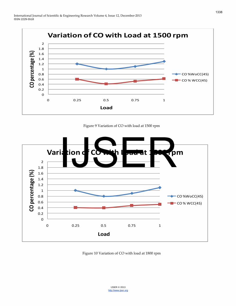
Figure 9 Variation of CO with load at 1500 rpm
0
0.2
0.4
0.6
0.8
1
1.2
1.4
1.6
1.8
2
0 0.25 0.5 0.75 1
CO p
erce
ntag
e (%
)
Load
Variation of CO with Load at 1800 rpm
CO %WoCC(4S)
CO % WCC(4S)
Figure 10 Variation of CO with load at 1800 rpm
1338
IJSER

International Journal of Scientific & Engineering Research Volume 4, Issue 12, December-2013 ISSN 2229-5518
IJSER © 2013
http://www.ijser.org
0
0.2
0.4
0.6
0.8
1
1.2
1.4
1.6
1.8
2
0 0.25 0.5 0.75 1
CO p
erce
ntag
e (%
)
Load
Variation of CO with Load at 2000 rpm
CO %WoCC(4S)
CO % WCC(4S)
Figure 11 Variation of CO with load at 2000 rpm
0
0.2
0.4
0.6
0.8
1
1.2
1.4
1.6
1.8
2
0 0.25 0.5 0.75 1
CO p
erce
ntag
e (%
)
Load
Variation of CO with Load at 2200 rpm
CO %WoCC(4S)
CO % WCC(4S)
Figure 12 Variation of CO with load at 2200 rpm
1339
IJSER
International Journal of Scientific & Engineering Research Volume 4, Issue 12, December-2013 ISSN 2229-5518
IJSER © 2013
http://www.ijser.org
200
300
400
500
600
700
800
900
1000
1100
1200
1300
0 0.25 0.5 0.75 1
HC
in P
PM
Load
Variation of HC with Load at 1500 rpm
HC PPM WoCC(4S)
HC PPM WCC(4S)
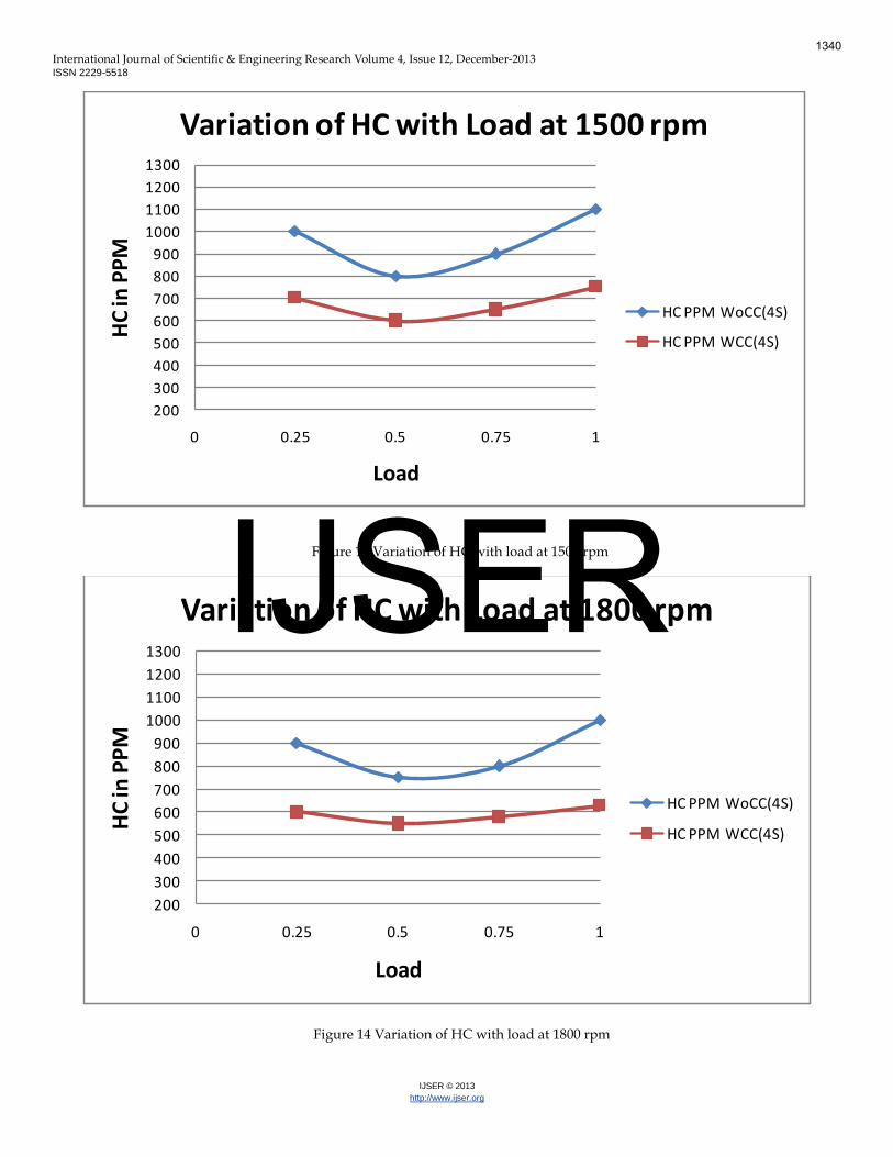
Figure 13 Variation of HC with load at 1500 rpm
200
300
400
500
600
700
800
900
1000
1100
1200
1300
0 0.25 0.5 0.75 1
HC
in P
PM
Load
Variation of HC with Load at 1800 rpm
HC PPM WoCC(4S)
HC PPM WCC(4S)
Figure 14 Variation of HC with load at 1800 rpm
1340
IJSER

International Journal of Scientific & Engineering Research Volume 4, Issue 12, December-2013 ISSN 2229-5518
IJSER © 2013
http://www.ijser.org
200
300
400
500
600
700
800
900
1000
1100
1200
1300
0 0.25 0.5 0.75 1
HC
in P
PM
Load
Variation of HC with Load at 2000 rpm
HC PPM WoCC(4S)
HC PPM WCC(4S)
Figure 15 Variation of HC with load at 2000 rpm
200
300
400
500
600
700
800
900
1000
1100
1200
1300
0 0.25 0.5 0.75 1
HC
in P
PM
Load
Variation of HC with Load at 2200 rpm
HC PPM WoCC(4S)
HC PPM WCC(4S)
Figure 16 Variation of HC with load at 2200 rpm
1341
IJSER