Experiment 11 11.1 Objectives 11.2 Introduction
23
Experiment 11 Color 11.1 Objectives • Observe the transmission properties of the three additive primary color filters and the three subtractive primary color filters. • Observe and interpret the color sensations resulting from mixing ad- ditive primary colors and mixing subtractive primary colors. • Be able to explain qualitatively the difference between additive and subtractive color mixing. 11.2 Introduction Color is something we often take for granted (unless we are artists). Grass is green, the sky is blue (well, maybe not in the winter). But how are these colors formed? How can I mix two colors of paint and end up with a third color? I can hear two different sounds at the same time, but why does nothing look like two different colors at the same time? Color is a complicated subject because it’s a combination of physics (wavelengths, frequencies, atomic spectra, light, etc.), the physiology of color as perceived by humans, and history. It’s somewhat muddled because through the history of painting and early attempts by Goethe and Newton to craft theories of color, some of the their language has stuck. 205
Transcript of Experiment 11 11.1 Objectives 11.2 Introduction
Experiment 11
Color
11.1 Objectives
• Observe the transmission properties of the three additive primarycolor filters and the three subtractive primary color filters.
• Observe and interpret the color sensations resulting from mixing ad-ditive primary colors and mixing subtractive primary colors.
• Be able to explain qualitatively the difference between additive andsubtractive color mixing.
11.2 Introduction
Color is something we often take for granted (unless we are artists). Grassis green, the sky is blue (well, maybe not in the winter). But how are thesecolors formed? How can I mix two colors of paint and end up with a thirdcolor? I can hear two different sounds at the same time, but why doesnothing look like two different colors at the same time?
Color is a complicated subject because it’s a combination of physics(wavelengths, frequencies, atomic spectra, light, etc.), the physiology ofcolor as perceived by humans, and history. It’s somewhat muddled becausethrough the history of painting and early attempts by Goethe and Newtonto craft theories of color, some of the their language has stuck.
205

11. Color
11.3 Key Concepts
As always, you can find a summary online at Hyperphysics1. Look forkeywords: light and vision, color, color vision, additive color mixing.
11.4 Theory
How do we see color?
As you experienced in last week’s lab, white light is composed of light fromall wavelengths in the visible range (400–700 nm) but why do we “see”different wavelengths as different colors? A picture (made using a beam ofelectrons) of a human retina is shown in Fig. 11.1. There are two types ofcells in the retina: rods (shown in green) and cones (shown in blue). Therod cells are sensitive to light and dark while our color vision is due to thecones. There are 3 types of cones and the relative response to the differentcones is interpreted by your brain as light of a particular color. One kindof cone is most sensitive to red; another is most sensitive to green; andthe third to blue. These three colors (red, green and blue) are called theadditive primaries, as they are typically combined together (positively)to create other colors.
Each type of cone (or color receptor) is actually sensitive to a range ofwavelengths and therefore colors. For example the “blue” cone responds tolight with wavelengths between 400 to 550 nm, or colors ranging from violetto indigo to blue. Fig. 11.2 shows which wavelengths of light each type ofcone is sensitive to and how sensitive they are. Notice that the human eyehas less sensitivity to “blue” than “red”. This is one reason that stop signsare red and not blue. The exact color we see is dependent on how mucheach type of cone is stimulated with respect to the others. For example,when green and red cones are simultaneously stimulated, we can see orangeor yellow, depending on how much more intense the red is with respectto the green. By mixing the three additive primary colors (R, G and B)with different intensities, we can generate all possible colors. For example,you can convince yourself that red and green make yellow by squinting atFig. 11.3.
In order for us to see anything at all, the light has to enter our eyes. Thelight can come directly from the light source, or it can be reflected from an
1http://hyperphysics.phy-astr.gsu.edu/hbase/hph.html
206 Last updated April 14, 2013

11.4. Theory
Figure 11.1: A picture of the human retina showing the rods (in green) andcones (in blue).
Figure 11.2: A plot showing the sensitivity of the 3 types of cones (red,green and blue) in a human eye.
Last updated April 14, 2013 207

11. Color
Figure 11.3: Squint at this and you’ll see yellow, yet no actual yellow coloris in the picture. This is Ferris Bueller’s moment with M. Seurat...and howcomic books work.
object. The red light at the top of a traffic signal is red because the lightsource is red. On the other hand, the red stop sign is red because it reflectsred light, and absorbs all other colors. These examples represent two kindsof color mixing, additive and subtractive, respectively.
Additive color mixing
In the case of additive color mixing, we are adding colors from more thanone light emitter. For example, mixing a red light and a green light withequal intensities will result in yellow light. Additive color mixing is used toform color images on the screen of older television and computer screens,called CRTs (“cathode ray tube”). The primaries used are red, green, andblue (from this point on, we’ll call them R, G, and B). You start from blackand add in the R, G and B colors to make the others. You cannot createblack with the additive primaries, rather you can create white. Fig. 11.4shows the additive color primaries at work. (You will mix these colors inthe lab.)
The color wheel that you see on your computer, as in Fig. 11.5, showsthe whole color spectrum. Notice that red, green, and blue are equidistantaround the edges. You will play with additive colors by creating mixturesof them in a light projection box.
Subtractive color mixing
The earliest thinking about color came from trying to understand painting.Rather than the adding light colors like in our (older) TVs, they had to con-tend with how to make particular colors on a canvas. This is a subtractive
208 Last updated April 14, 2013

11.4. Theory
Figure 11.4: Colors adding to-gether in a light projectionbox.
Figure 11.5: RGB color se-lection on a computer appro-priate for viewing on a screen(additive).
process: light from a source, like the sun, falls on the surface of an object(or set of pigments) and is reflected. But not all wavelengths are reflected;just some reach our eyes which we interpret as the color of that object asin Fig. 11.4. The painter’s job is to mix the right pigments together inorder to cause other humans to “see” the color he or she desired. Said morespecifically, the painter chooses the pigments necessary in order to take outthe wrong colors from light that reflect from the surface, leaving the desiredcolor. So color is not an attribute of just the object: it’s a combination ofthe reflection or absorption of light (atomic physics) and our interpretationof that light through our highly-evolved eyeballs (physiology).
The subtractive primaries are a convention following a long historyof painting and printing. They are now usually Cyan, Magenta, and Yellow(from this point on, we’ll call them C, M, and Y). Painters like them because
Last updated April 14, 2013 209

11. Color
Figure 11.6: This is another way to make yellow: all colors fall on thesurface of the banana and are absorbed except the yellow.
Figure 11.7: You’ve seen this on your computer as well. It’s the colorselection appropriate for printing (subtractive).
210 Last updated April 14, 2013

11.4. Theory
you can get the truest black using these three colors (which you’ll do).2
Filters
A filter is a semi-transparent film which passes some wavelengths and notothers. Let’s deal with the Additive Primaries (R, B, G) and the SubtractivePrimaries (C, Y, M) only. Remember: White light is a mixture of allof the colors, a controversial fact first worked out by Isaac Newton. Soif you pass white light through a filter that removes all wavelengths but Rthen you’d call that a Red Filter. Likewise, for B and G. Filters are notperfect: a red filter doesn’t pass only a single wavelength, but rather a bandof wavelengths which are reddish. You’ll measure these bands in this lab.
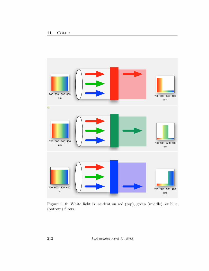
Let’s picture the effects of filters on the Additive and Subtractive Pri-maries in Figs. 11.8–11.9. In each picture, white light is incident from theleft, passes through a filter, and only particular wavelengths of light emergeon the right. The little spectrum window (on the far right) shows the effectson the spectrum of visible light.
Fig. 11.8 shows what happens when white light is passed through filtersthat are the additive primary colors (R, G, B). Notice that if you pass whitelight through a red filter only “red” (or the reddish wavelengths of) light istransmitted. In addition it might not be too surprising that if you pass redlight through a red filter, all you get is red light out. But what happensif you pass red light through a blue filter? The blue filter only transmitslight with wavelengths around 400-500 nm, but “red” light has wavelengthsaround 600-700 nm. Does any of the red light make it through a blue filter?
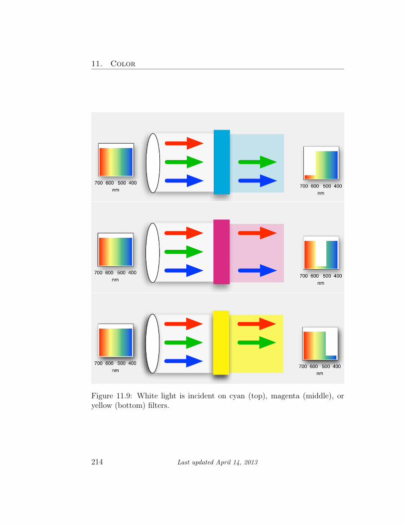
The Subtractive Primary colors (C, M, Y) can also be fashioned intofilters, but here something different happens because both the physics andour perception is different. Fig. 11.9 shows the results when white lightenters from the left and passes through:
. . . a cyan filter — to produce cyan colored light. It does that by remov-ing the longest wavelengths (reddish) leaving the rest, which is representedin the top picture as green and blue arrows. (Look at the color wheel:the cyan filter removes its complementary color on the opposite side of thewheel, i.e. red.)
2Sometimes you see printers using CMYK, where K stands for “key”, which is notblack, per se, but a printer-specific designation for the black “key” plate that prints thedetail and is, in fact, black.
Last updated April 14, 2013 211
11. Color
Figure 11.8: White light is incident on red (top), green (middle), or blue(bottom) filters.
212 Last updated April 14, 2013
11.4. Theory
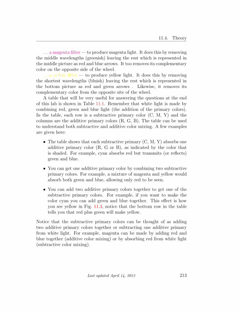
. . . a magenta filter — to produce magenta light. It does this by removingthe middle wavelengths (greenish) leaving the rest which is represented inthe middle picture as red and blue arrows. It too removes its complementarycolor on the opposite side of the wheel.
. . . a yellow filter — to produce yellow light. It does this by removingthe shortest wavelengths (bluish) leaving the rest which is represented inthe bottom picture as red and green arrows . Likewise, it removes itscomplementary color from the opposite site of the wheel.
A table that will be very useful for answering the questions at the endof this lab is shown in Table 11.1. Remember that white light is made bycombining red, green and blue light (the addition of the primary colors).In the table, each row is a subtractive primary color (C, M, Y) and thecolumns are the additive primary colors (R, G, B). The table can be usedto understand both subtractive and additive color mixing. A few examplesare given here:
• The table shows that each subtractive primary (C, M, Y) absorbs oneadditive primary color (R, G or B), as indicated by the color thatis shaded. For example, cyan absorbs red but transmits (or reflects)green and blue.
• You can get one additive primary color by combining two subtractiveprimary colors. For example, a mixture of magenta and yellow wouldabsorb both green and blue, allowing only red to be seen.
• You can add two additive primary colors together to get one of thesubtractive primary colors. For example, if you want to make thecolor cyan you can add green and blue together. This effect is howyou see yellow in Fig. 11.3, notice that the bottom row in the tabletells you that red plus green will make yellow.
Notice that the subtractive primary colors can be thought of as addingtwo additive primary colors together or subtracting one additive primaryfrom white light. For example, magenta can be made by adding red andblue together (additive color mixing) or by absorbing red from white light(subtractive color mixing).
Last updated April 14, 2013 213
11. Color
Figure 11.9: White light is incident on cyan (top), magenta (middle), oryellow (bottom) filters.
214 Last updated April 14, 2013

11.4. Theory
white light red green blue
(contains all wavelengths) long λ medium λ short λ
subtractive primary:
cyan (absorbs red) red green blue
magenta (absorbs green) red green blue
yellow (absorbs blue) red green blue
Table 11.1: For a given subtractive primary color that subtracts fromwhite light, this table shows which colors are absorbed and which are re-flected/transmitted. Colors with a gray background and in bold are ab-sorbed.
Van Gogh was the master of complementary colors, especially yellowswith blues. One of the things about complementaries is that we seestark contrasts between them and we perceive a sense of stability. Nophysics here, it’s physiology and psychology — artistic genius.
The Cafe Terrace on the Place du Forum, Arles, at Nightby Vincent van Gogh (1888)
Last updated April 14, 2013 215

11. Color
11.5 In today’s lab
In this experiment, we will use subtractive color mixing by filters rather thanby pigments, since filters are more easily manipulated in the laboratory. Youwill measure the bands of light that the filters allow through (transmit).
11.6 Equipment
• Digital spectrometer from the previous lab, but with an absorptome-ter with integrated sampling system that creates light internally andpasses it through insertable filters for digitization (Ocean Optics USB650Red Tide, see Fig. 11.10)
• Computer with Logger Pro installed
• One empty cuvette3 for calibration (the clear tube in Fig. 11.10(a))
• Set of 3 additive primary (R,G,B) filters each in their own cuvettes, 3subtractive primary (C,M,Y) color filters in theirs, an empty cuvettefor calibration and one cuvette with two filters in the same tube (thereshould be a total of 8 cuvettes at your bench). Do not open thecuvettes!
• Light projection box at the front of the room
• LED desk lamp
3A “cuvette” is a glass or plastic holder designed to hold objects destined for spec-troscopic analysis. It’s pronounced “coo-vette” as in “corvette.”
216 Last updated April 14, 2013

11.7. Procedure
(a) Cuvette (clear box) sitting on top (b) Cuvette inserted.
Figure 11.10: Digital spectrometer with integrated sampling system, shownwith cuvette both uninserted and inserted.
11.7 Procedure
Setup
1. Start the data-collection program Logger Pro and choose New fromthe File menu.
2. Make sure the power supply for the fan is plugged into the part of thedigital spectrometer that is labeled “USB-ISS-UV-VIS”.
3. Connect the spectrometer to the USB port of the computer. Wait afew seconds for the light and fan to come on inside the spectrometer(you will hear a click as the shutter opens and then the fan shouldcome on). If you find that nothing appears on the computer screenwhen you try to collect data then unplug and plug back in the USBcable to the spectrometer with Logger Pro already running.
4. Calibrate the spectrometer:
a) Place the empty cuvette in the square hole in the top of thespectrometer (see Fig. 11.10); make sure to align the cuvette sothat the frosted sides are parallel with the long edge of the wholedevice (this ensures that the clear sides are facing the light sourceof the spectrometer).
Last updated April 14, 2013 217

11. Color
b) In Logger Pro, from the drop-down menus, choose Experiment
� Calibrate � Spectrometer: 1.
c) When the warmup period is complete, select Finish Calibration.
d) Select OK.
Absorption spectra of filters
For each of the additive primary color filters (R, G, B):
1. Insert the cuvette with the desired filter into the sample holder, pressthe “Collect” button in Logger Pro, and observe the spectrum thatresults. If the spectrum is not visible or is cut off at the top of thegraph, right click on the y-axis label Absorbance, select Autoscale� Autoscale.
Note that the plot is an absorption spectrum. The larger theabsorption value the more that wavelength is absorbed by thefilter and NOT detected by the spectrometer. A value close tozero means that the wavelength was nearly totally transmitted.Notice that this is the opposite of what you did in the last labwhere you were looking at emission spectra. In this experimenta peak means that that wavelength is missing (it was absorbed)and a zero value means it can be seen (it was transmitted). Keepthis in mind when you fill in the table in Question 1.
2. Write down your observations for each filter in the table under Ques-tion 1. Describe which colors are transmitted and record the wave-length ranges of the resulting absorption spectra. Note that you maysee a continuous band of colors (the “main” band), then a gap, and anarrower range of colors.
3. Print out the curves from the R, G and B filters all on 1 graph.You can do this by hitting “collect” when starting the next filter andchoosing the option to keep the previous result in the dialog box.
4. Label each curve by going to Insert � Text Annotation. A textbox will appear and you can grab the end of the line with the mouseand point it at the curve that you’ve referenced.
218 Last updated April 14, 2013

11.7. Procedure
5. Answer Questions 2–3.
6. Repeat steps 1 – 4 from above for each of the subtractive primarycolor filters (C, M, Y) and print their curves on 1 graph.
For this part of the lab you will turn in 2 graphs taken with the spec-trometer: one for the additive primaries (R, G, and B) and one for thesubtractive primaries (C, M, and Y). Make sure to label all of the curves.
Additive color mixing
In this part of the experiment you will use the light projection box to observeadditive color mixing. The projection box is the large black box located inthe front of the room. It contains three different independent light sources.The knobs on the sides let you adjust the intensity of each of the lightsindependently. For example, by adjusting the knobs so that the blue lightis off and the red and green lights are of equal intensity, you can see whatcolor is produced where they overlap. You can make accurate predictions ofwhat colors to expect using Table 11.1. When answering the questions forthis section: make your predictions first, then observe the result usingthe projection box. Record both in the table given in Question 4 and thenanswer Question 5.
Subtractive color mixing
In this section you will experience subtractive color mixing and understandhow it differs from additive color mixing. Here you will use the LED desklamp (which is approximately white light) on each table. At the front of theroom will be several manilla envelopes containing different colored filters.You will need a few pieces of each color. By stacking different color filterson top of each other, you can see what the resultant color is. Some of thefilters are not very efficient (as you saw earlier in the lab), so you may wantto use more than one of the same color. For example, when completingthe first line of the table in Question 6 try stacking two red and two bluefilters together. Use Table 11.1 to make your predictions first, thenobserve what happens when letting light from the desk lamp pass throughthe filters. Record your predictions and observations in Question 6 andanswer Questions 7–12. For Question 10 you will use the cuvette with 2filters in it and print out the graph from the spectrometer.
Last updated April 14, 2013 219


11.8. Questions
11.8 Questions
1. Record your observations below:
filter colors transmitted (note gaps) range transmitted (main band)
min wavelength (nm) max
red
green
blue
cyan
magenta
yellow
Last updated April 14, 2013 221

11. Color
2. If you had an ideal “red” filter, what colors would be absorbed?
3. How well do the R, G and B filters match the colors you expected?Would you say that the filters are “ideal”?
222 Last updated April 14, 2013

11.8. Questions
Additive color mixing
4. Record your predictions and observations in the following table.
light mixture predicted color observed color
red + green
red + blue
green + blue
red + green + blue
5. How well did your predictions agree with your results? Explain anydifferences.
Last updated April 14, 2013 223
11. Color
Subtractive color mixing
6. Record your predictions and observations in the following table.
filter mixture predicted color observed color
red + blue
blue + yellow
cyan + magenta
cyan + yellow
magenta + yellow
cyan + magenta + yellow
224 Last updated April 14, 2013

11.8. Questions
7. Why does “red + blue” give different results in this part of the ex-periment compared to the part with the projector box? Explain whatcaused the results for red + blue to be different in each case (that is,explain how each case, additive vs. subtractive, works).
8. Explain the results for cyan + yellow.
Last updated April 14, 2013 225

11. Color
9. For blue + yellow, did the color you observe match your prediction?If it didn’t, then why not? What wavelengths of light must the filterslet through?
10. Check this with the spectrometer by using the cuvette that has twofilters (a blue and a yellow) in it. Did you accurately estimate whichwavelengths the filters would let through? If not, which wavelengthsdid the filters let through? Print out the graph from the spectrometer.
226 Last updated April 14, 2013

11.8. Questions
11. Give a practical example from everyday life of additive and subtractivecolor mixing. (You must give a different example than the stop signand stop light from the write-up.)
12. Why is it harder to think of examples of additive color mixing?
Last updated April 14, 2013 227