EXPERIMENT-1 AIM APPARATUS USED: CONSTRUCTION DETAILS
34
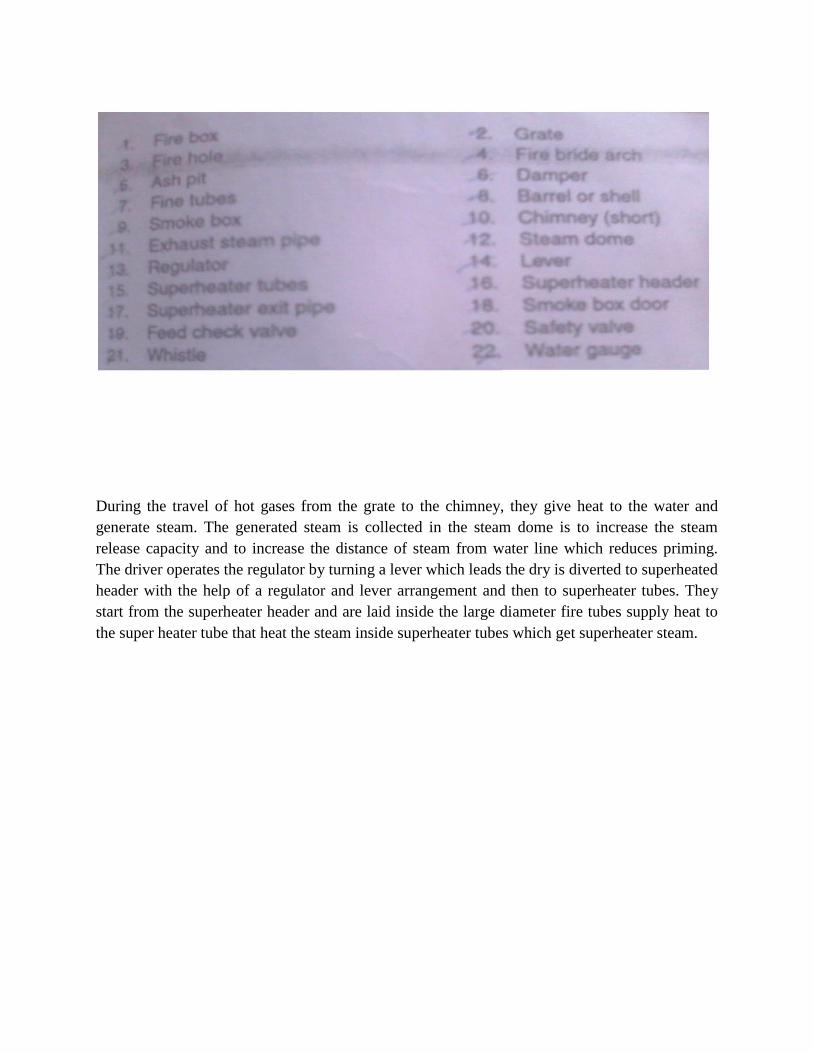
EXPERIMENT-1 AIM: To study and sketch about the Locomotive Boiler. APPARATUS USED: The model of Locomotive Boiler INTRODUCTION: The Locomotive Boiler is horizontal, multi-tubular, natural circulation, internally fired, fire tube boiler. The maximum pressure range 21bar and streaming rate is as high as 55 to 70 Kg per square meter of heating surface per hour. CONSTRUCTION DETAILS: It consists of cylindrical steel shell. There is a rectangular fire box at the back end of the shell which forms a combined grate and combustion chamber. The main parts of the locomotive boiler are given below: 1. Fire Box 2. Grate 3. Fire Hole 4. Fire Bridge Arch 5. Damper 6. Ash Pit 7. Fine Tube 8. Cylindrical Barrel or Shell 9. Smoke Box 10. Chimney 11. Exhaust Steam Pipe 12. Steam Dome 13. Regulator 14. Super Heater Tubes 15. Super Heater Header 16. Super Heater Exit Tube 17. Smoke Box Door 18. Feed Check Valve 19. Safety Valve 20. Water Gauge
Transcript of EXPERIMENT-1 AIM APPARATUS USED: CONSTRUCTION DETAILS

EXPERIMENT-1
AIM: To study and sketch about the Locomotive Boiler.
APPARATUS USED:
The model of Locomotive Boiler
INTRODUCTION:
The Locomotive Boiler is horizontal, multi-tubular, natural circulation, internally fired, fire tube
boiler. The maximum pressure range 21bar and streaming rate is as high as 55 to 70 Kg per
square meter of heating surface per hour.
CONSTRUCTION DETAILS:
It consists of cylindrical steel shell. There is a rectangular fire box at the back end of the shell
which forms a combined grate and combustion chamber. The main parts of the locomotive boiler
are given below:
1. Fire Box
2. Grate
3. Fire Hole
4. Fire Bridge Arch
5. Damper
6. Ash Pit
7. Fine Tube
8. Cylindrical Barrel or Shell
9. Smoke Box
10. Chimney
11. Exhaust Steam Pipe
12. Steam Dome
13. Regulator
14. Super Heater Tubes
15. Super Heater Header
16. Super Heater Exit Tube
17. Smoke Box Door
18. Feed Check Valve
19. Safety Valve
20. Water Gauge

WORKING PROCESS
The coal is burnt in the fire box and produces the hot flue gases. These flue gases rising from the
grate are deflected upwards by a fire bridge and so that its come into contact with the walls and
roof of the fire box. Due to the motion of the locomotive a strong draught is created and the
atmospheric air rushes into the fire box through the dampers. The function of the dampers is to
control the quantity of air entering in the fire box. The ash of the coal burnt on the grate falls into
the ash pit. The hot flue gases pass from the furnace box to the smoke box through horizontal
smoke tubes. A large door in the front of the smoke box gives access to it and the tubes for
examination and cleaning purposes. The hot gases from the smoke box are discharged to the
atmosphere through a short chimney.
During the travel of hot gases from the grate to the chimney, they give heat to the water and
generate steam. The generated steam is collected in the steam dome is to increase the steam
release capacity and to increase the distance of steam from water line which reduces priming.
The driver operates the regulator by turning a lever which leads the dry is diverted to superheated
header with the help of a regulator and lever arrangement and then to superheater tubes. They
start from the superheater header and are laid inside the large diameter fire tubes supply heat to
the super heater tube that heat the steam inside superheater tubes which get superheater steam.

EXPERIMENT-2
AIM- To study and sketch about Lancashire Boilers
APPARATUS USED:
Model of Lancashire Boilers
INTRODUCTION:
A Lancashire Boiler is fire tube boiler. Its normal working pressure range is 15 bar and steaming
capacity is about 8000 Kg/h. Its size varies from about 8 meters to 9 meters in length and from 2
to 3.5 meters in diameter.
CONSTRUCTION DETAILS:
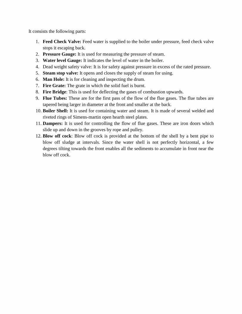
It consists the following parts:
1. Feed Check Valve: Feed water is supplied to the boiler under pressure, feed check valve
stops it escaping back.
2. Pressure Gauge: It is used for measuring the pressure of steam.
3. Water level Gauge: It indicates the level of water in the boiler.
4. Dead weight safety valve: It is for safety against pressure in excess of the rated pressure.
5. Steam stop valve: It opens and closes the supply of steam for using.
6. Man Hole: It is for cleaning and inspecting the drum.
7. Fire Grate: The grate in which the solid fuel is burnt.
8. Fire Bridge: This is used for deflecting the gases of combustion upwards.
9. Flue Tubes: These are for the first pass of the flow of the flue gases. The flue tubes are
tapered being larger in diameter at the front and smaller at the back.
10. Boiler Shell: It is used for containing water and steam. It is made of several welded and
riveted rings of Simens-martin open hearth steel plates.
11. Dampers: It is used for controlling the flow of flue gases. These are iron doors which
slide up and down in the grooves by rope and pulley.
12. Blow off cock: Blow off cock is provided at the bottom of the shell by a bent pipe to
blow off sludge at intervals. Since the water shell is not perfectly horizontal, a few
degrees tilting towards the front enables all the sediments to accumulate in front near the
blow off cock.
EXPERIMENT-3
AIM- To study and sketch about the model of Babcock Wilcox Boiler
APPARATUS USED:
Model of Babcock Wilcox Boiler
INTRODUCTION:
Babcock Wilcox Boiler is a water tube boiler. Evaporative capacity of such boilers ranges from
20,000 to 40,000 kg/hr of steam and operating pressure is about 40 bar.
CONSTRUCTION:
It consists of high pressure drum mounted at the top. From each end of the drum connections are
made with the upper header and down tube header. A large number of water tubes connects the
uptake and down take header. The water tubes are inclined 25 to 35 degree to promote water
circulation. The heating surface of the unit is the outer surface of the tubes and half of the
cylindrical surface of water drum which is exposed to flue gases. A mud box is attached to the
bottom of the down take header.
The whole of the assembly of water tubes is hung along with the drum from steel girder frame by
steel rods called slings in a room made of masonary work, lined with fire bricks. Below the
uptake header the furnace of boiler is arranged. The coal is fed to chain grate stoker. There is a
bridge wall deflector which deflects the combustion gases upwards. Two baffles are also
arranged which provide three passes of the flue gases. A damper is placed at the inlet of the
chimney to regulate the draught. Different other mountings and accessories are given below:
Pressure Gauge, Water gauge, safety valve, feed water inlet, Headers, Non return
valve, Anti priming pipe, Super heater, Baffles, Fire Grate, Ash Pot, Clean out doors, Riser,
Blow off pipe, Damper etc.

WORKING PROCESS:
The hot combustion gases caused by burning of fuel on the grate rise upwards and are deflected
by the bridge wall deflection and pass over to the front portion of the water tubes and drum. In
this way they complete the pass, with provision of baffles they deflect downwards and complete
second pass. Again with the provisions of baffles they rise upwards and complete the third pass
and finally come out through the chimney. During their travel they give heat to water and steam
is formed. The circulation of water in boiler is natural circulation set up by convective currents.
Feed water supplied by a feed water inlet pipe. The hottest water and steam rises from
the tubes to the uptake header and then through the riser enters the boiler drum. The steam
vapours escape through the water to upper half of the drum. The cold water flows from the drum
to the down take header and thus the cycle is completed. The flue gases passing over the flue
tubes produce superheated steam. The steam thus superheated is finally supplied to be used
through a steam stop valve. The super heaters remains flooded until the steam reaches the
working pressure. The superheater is then drained and steam is allowed to enter in it for
superheating purposes.
USES:
The Babcock Wilcox Boiler is used in electric power plants for running steam turbines.

EXPERIMENT-4
AIM- To study and sketch Simple Steam Engine Model
APPARATUS USED:
Steam Engine Model
INTRODUCTION:
The steam engine is a reciprocating type prime mover which utilizes steam as the working
medium to convert heat energy into mechanical energy. It is also known as external combustion
engine.
MAIN PARTS OF SIMPLE STEAM ENGINE
Cylinder: This is the chamber in which the piston moves to and fro due to the action of steam.
Steam Chest: This is generally cast integral with the cylinder. There are two ports called inlet
port and outlet port made in the casting for connecting the steam chest to he cylinder.
Piston: This is made of cast iron and moves to & fro in the cylinder by the action of steam.
Piston Rings: The function of piston rings is to prevent the leakage of steam and any wear and
tear taking place in the cylinder.
Piston Rod: The piston rod connects the piston and cross head and is made of mild steel.
Cross head: It connects the piston rod and connecting rod and moves between guides.
Connecting rod: It is made of forged steel. One end of connecting rod is connected to the cross
head by gudgeon pin and other end is connected to the crank.
Crank shaft: It is made of alloy steel. The crank shaft is main part of steam engine which serves
the purpose of converting the force applied by the connecting rod into a rotational force.
Valve: It reciprocates over the valve seat in the steam chest by the eccentric so located on the
crank shaft relative to crank so as to admit or exhaust steam to & from the cylinder at the proper
time through the port.
Valve rod & Eccentric rod: The valve rod connects the valve and the eccentric rod through a
valve rod guide which prevents the bending of the valve rod while the eccentric rod connects the
valve rod and eccentric.
Governor: The function of governor is to maintain the speed of engine fairly constant
irrespective of the load.
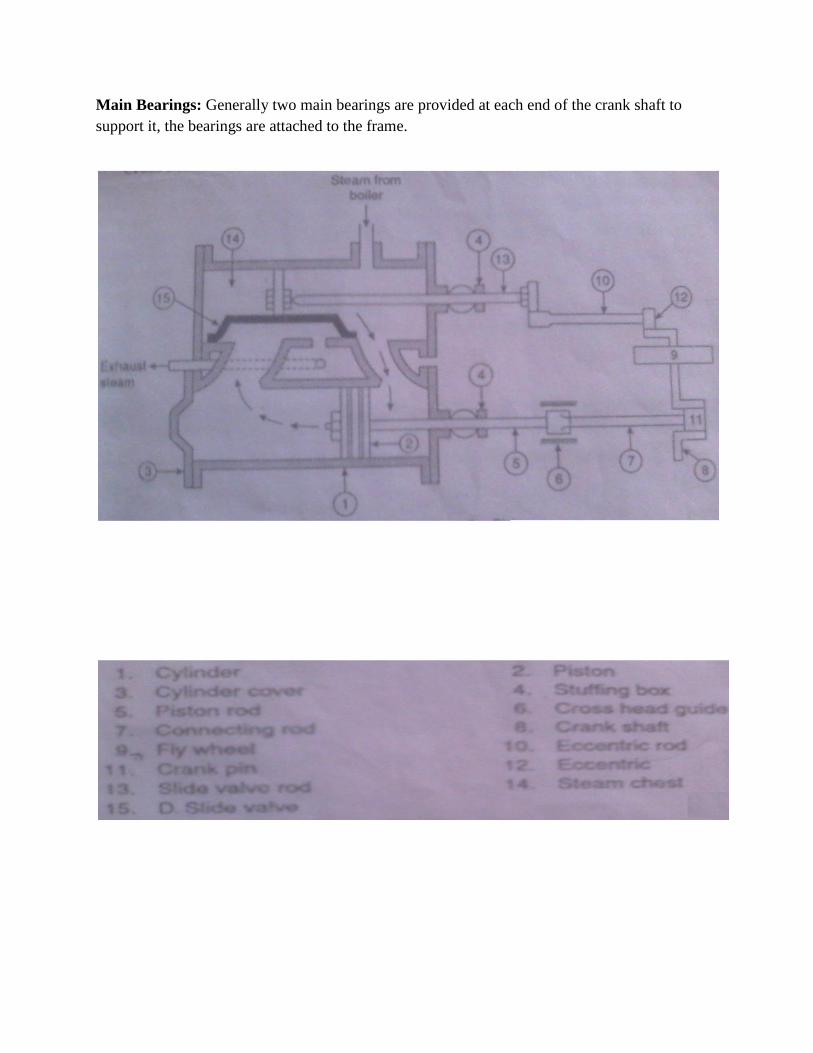
Main Bearings: Generally two main bearings are provided at each end of the crank shaft to
support it, the bearings are attached to the frame.

WORKING PROCESS OF STEAM ENGINE:
Consider a simple, double acting non condensing, D-slide valve type engine. Let the piston is at
the cover end position of the cylinder and ready for the forward stroke. Now the valve opened
the inlet port. The high pressure steam from the boiler enters the cylinder through the steam
chest. The pressure of steam pushes the piston, thus performing the forward stroke. The motion
of piston moves the crank, shaft and eccentric. The delivery valve just uncovered and the used
steam from the previous stroke becomes free and escapes to the exhaust pipe.
Admission of steam continues to occur till the eccentric has moved the valve to close the
inlet port, thus cutting off the steam, the steam now expands and the volume of steam increases
so that the pressure falls. This fall in pressure makes the steam performs the work. Before the
end of forward stroke, the valve opens the same inlet port to the exhaust side and steam is
released. After releasing the steam, the piston reverses its motion performing the return stroke.
Now delivery port opens and fresh steam enters the cylinder which pushes the piston inward to
complete the inward stroke. When the piston nearly reaches its end of the return stroke the valve
closes the inlet port to exhaust the steam. The steam entrapped between the piston & cylinder
head is compressed till the piston reaches to the corner end. Now the cycle is completed and the
piston is ready for the next cycle.
Applications:
Steam engines are used in the following:
1. For driving pumps & Compressors
2. In locomotive & hoisting where reverse operation and wide flexibility in speed control
are required.

EXPERIMENT-5
AIM: To study and sketch about vapour compression refrigeration system.
APPARATUS USED:
Model of vapour compression refrigerator
INTRODUCTION:
The principle of Vapour Compression Refrigeration Cycle involves the condensing and
evaporating of the refrigerant (liquid gas) again and again. The liquid gases CO, NH, Freon-12,
Freon-22 etc. are used as refrigerant for the above cycle. During evaporation, the refrigerant
absorbs a large amount of heat from the brine circulating around evaporating unit. During
condensation, the refrigerant gives out latent heat to water circulating in the condenser.
MAIN PARTS OF VAPOUR COMPRESSION REFRIGERATOR:
A simple vapour compression system of refrigeration consists of four main parts:
(i) Compressor
(ii) Condenser
(iii) Expansion valve
(iv) Evaporator
WORKING PROCESS:
The working process of vapour compression refrigerating system is followed in these sequences:
(i) Compression process: The compression of vapour takes place from low pressure
and low temperature to high pressure and high temperature. If initial state of the
vapour is saturated or superheated, the compression is called Dry Compression. If the
initial state of the vapour is wet, the compression is called Wet Compression. The
reciprocating compressor is generally used in the refrigerators.
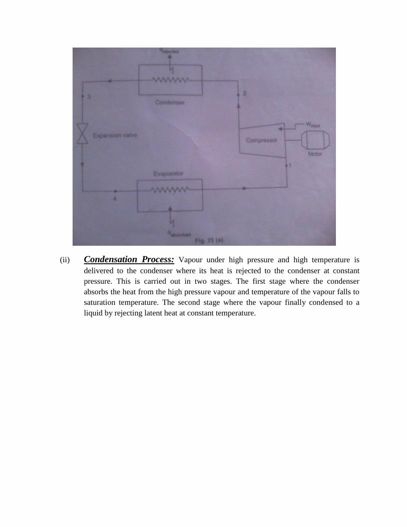
(ii) Condensation Process: Vapour under high pressure and high temperature is
delivered to the condenser where its heat is rejected to the condenser at constant
pressure. This is carried out in two stages. The first stage where the condenser
absorbs the heat from the high pressure vapour and temperature of the vapour falls to
saturation temperature. The second stage where the vapour finally condensed to a
liquid by rejecting latent heat at constant temperature.
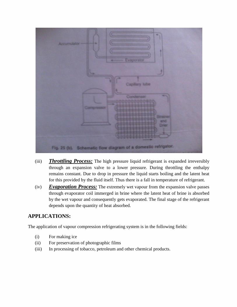
(iii) Throttling Process: The high pressure liquid refrigerant is expanded irreversibly
through an expansion valve to a lower pressure. During throttling the enthalpy
remains constant. Due to drop in pressure the liquid starts boiling and the latent heat
for this provided by the fluid itself. Thus there is a fall in temperature of refrigerant.
(iv) Evaporation Process: The extremely wet vapour from the expansion valve passes
through evaporator coil immerged in brine where the latent heat of brine is absorbed
by the wet vapour and consequently gets evaporated. The final stage of the refrigerant
depends upon the quantity of heat absorbed.
APPLICATIONS:
The application of vapour compression refrigerating system is in the following fields:
(i) For making ice
(ii) For preservation of photographic films
(iii) In processing of tobacco, petroleum and other chemical products.
EXPERIMENT-6
AIM- To study the model of gas turbine
INTRODUCTION & THEORY:
Gas turbine is a rotary type internal combustion thermal prime mover. The gas turbine plant
works on a gas power cycle. It obtains its power by utilizing the energy of a jet of burnt gases
and air, the velocity of jet being absorbed as it flows over several rings of moving blades, which
are fixed to a common shaft. It thus resembles a steam turbine, but it is a step forward in
eliminating water-to-water step (the process of converting water into steam in a boiler) and using
hot gases directly to drive the turbine.
The main operations of a gas turbine plant consist:
(i) The compression of cool air in a rotary compressor
(ii) The heating of this air by the combustion of fuel in the combustion chamber
(iii) The expansion of this hot high pressure gas in a turbine
The compressor is usually coupled to the turbine and directly driven by the turbine and lowers
the overall efficiency of the gas turbine power plant. The turbine output should therefore be
sufficient to produce a useful output in addition to the power required to drive the compressor.
Another drawback of a gas turbine plant is that it is not self-starting. Against these drawbacks,
the outstanding advantage of the gas turbine lies in the successful use of pulverized coal as fuel.
The Gas turbine plant finds its applications in
a) Stationary power plant
b) Locomotive propulsion
c) Ship propulsion
d) Aviation
e) Automotive
f) Combination with steam power plant
TURBOJET ENGINES
The Turbojet engine is similar to the similar constant pressure gas turbine plant, except that the
exhaust gases are first partially expanded in the turbine to produce just sufficient power to drive
the compressor. The exhaust gases leaving the turbine are then expanded to atmospheric pressure
in a propelling (discharge) nozzle The remaining energy of gases after leaving the turbine is used
as a high-speed jet, which the thrust is obtained. In turbojet engine, the thrust is completely due
to jet of exhaust gases.

Thus, the essential components of a turbojet engine are:
(i) An entrance air diffuser in front of the compressor, which causes rise in pressure in
the entering air by slowing it down in the diffuser. This is known as ram.
(ii) A rotary compressor, which raises the pressure of air further, required value and
delivers it to the combustion chamber. The compressor is driven by the turbine.
(iii) The combustion chamber, in which paraffin (kerosene) is sprayed, as a result of this,
combustion takes place at constant pressure.
(iv) The gas turbine into which products of combustion pass on leaving the combustion
chamber. The products of combustion are partially expanded in the turbine to
provided necessary power to drive the compressor.
(v) The discharge nozzle in which expansion of gases is completed, thus developing the
forward thrust.
WORKING CYCLE
Air from surrounding atmosphere is drawn in through the diffuser, in which air is compressed
partially by ram effects. Then air enters the rotary compressor and major part of the pressure rise
is accomplished here. The air is compressed to a pressure of about 4 atmospheres. From the
compressor the air passes into the annular combustion chamber. The fuel is compressed to a high
pressure in the oil pump and is forced through the fuel nozzle into the combustion chamber.
Here, the fuel is burnt at constant pressure. This raises the temperature and volume of the
mixture of air and products of combustion. The weight of air supplied is about 60 times the
weight of fuel burnt. This excess air produces sufficient mass for the propulsion jet, and at the
same time prevents gas temperature from reaching values, which are too high for the metal of the
rotor blades.
The hot gases from the combustion chamber then pass through the turbine nozzle ring. The hot
gases, which partially expand in the turbine, are then exhausted through the discharge
(propelling) nozzle, by which the remaining pressure energy is converted into kinetic energy.
Thus, a high velocity propulsion jet is produced.
The oil pump and compressor are mounted on the same shaft as the turbine rotor. The power
developed by the turbine is spent in driving the compressor and the oil pump. Some starting
device such as compressed air motor or electric motor must be included in the turbojet plant.
Speeds up to 800 kilometers per hour are obtained from this type of unit.
RESULT:
Model of Turbojet Engine has been visualized and studied.

EXPERIMENT-7
AIM- To Study and sketch about the principle and working of two stroke Diesel Engine
INTRODUCTION:
The fuel is supplied with the help of fuel injection pump and the injection to the cylinder.
The working of diesel engine is similar to two stroke S.I Engine except that only air is
induced into the crank case in case of C.I Engine in place of mixture of fuel and air.
MAIN PARTS OF THE C.I ENGINE:
1) Cylinder-
It is hollow cylinder, one side of which is closed by cylinder head and is made of cast
iron. Cylinder head usually contains both the valves and fuel injector or Spark Plug.
The internal diameter of cylinder is called Bore.
2) Piston-
The Piston is made of cylindrical casting of iron or aluminium alloy. The main
function of the piston is to transmit the force created by combustion products to the
connecting rod.
3) Piston Rings-
It is made of grey cast iron.
4) Connecting Rod-
The function of connecting rod is to convert the reciprocating motion of the piston
into rotary motion of crankshaft. It is made of forged steel.
5) Crank shaft-
It controls the motion of piston and is made of forged alloy steel or carbon’s steel.
WORKING OF THE C.I ENGINE:
The fuel is supplied with the help of fuel injection pump and the injector to the
cylinder. The working of diesel engine is similar to two stroke S.I Engine except that
only air is induced into the crank case in case of C.I Engine in place of mixture of
fuel and air. Consider the piston at T.D.C when piston moves down, the hot gases
expand. During its downward motion, the piston firstly uncovers the exhaust port and
a little later it uncovers the transfer port.

The air compressed during the previous stroke in the crankcase is transferred
into the cylinder via the transfer port. This incoming air pushes out the burnt
gases while passing over the deflection. This process of sweeping out the
burnt gases is called Scavenging
The piston moves upwards i.e. from B.D.C to T.D.C. It first closes the transfer
port and a little later the exhaust port.
The air transfer earlier into the cylinder is now compressed with further
movement of piston upwards.
Before the end of compression stroke, the fuel is injected and the atomized
fuel burns due to high temperature of air called Auto-ignition.
The resultant hot gases will again expand, thus completing a cycle.
APPLICATIONS:
1. I.C Engines are used in all road vehicles
2. I.C Engines are widely used in rail road, aviation, marine etc.
3. I.C Engines are extensively used in lawn movers, motor boats, concrete
mixing equipment etc.

EXPERIMENT-8
AIM- To Study and sketch about the principle and working of two stroke I.C. Engine or Petrol
Engine
INTRODUCTION:
The internal combustion engine is a heat engine in which the energy of fuel air mixture is
released by combustion in the engine cylinder itself. The heat energy increases the pressure and
temperature of the cylinder gas and subsequent expansion of the gas converts the heat energy
into mechanical work.
MAIN PARTS OF THE I.C ENGINE OR PETROL ENGINE
1) Cylinder:
It is hollow cylinder, one side of which is closed by cylinder head and is made of cast
iron. The fuel is burnt inside of the cylinder and power is developed due to reciprocating
motion of the piston.
2) Piston:
The piston is made of cylindrical casting of iron or aluminium alloy. The piston is
accurately machined to running fit in the cylinder bore and is provided with several
grooves into which piston rings are fitted.
3) Piston Rings:
The piston is made of cylindrical casting of iron or aluminium alloy. The function of the
piston rings is to prevent any leakage of gas past the piston and to prevent the wear of the
piston.
4) Connecting Rod:
The Connecting Rod connects the piston and crank pin. The function of connecting rod is
to convert the reciprocating motion off the piston into rotary motion of crankshaft.
5) Crank Shaft:
The crankshaft is the principle rotating part of the engine. It serves to convert the forces
applied by the connecting rod into rotational force.
WORKING OF TWO STROKE PETROL ENGINE:
In this type of engine the valves of the four stroke engine are replaced by
ports which are three in number namely, transfer port, inlet or induction port and exhaust
port.
When the piston moves from TDC to BDC, the burnt gases expand and develop the
motive power. When the piston moves downwards during its expansion stroke, the piston
first covers the inlet port and compresses the fresh charge held in the crank case. After
the completion of about 80% expansion stroke, the piston uncovers the exhaust port and
some of the products of combustion escape to atmosphere.
On further motion of the piston, the piston uncovers the transfer port and allows
the slightly compressed charge from the crank case to be admitted into the cylinder via
the transfer port.
The top of the piston usually has a deflector. The fresh charge sweeps
out the remainder of the burnt gases while passing over the deflector. During the upward
motion of the piston from BDC to TDC, the piston first uncovers the inlet port allowing
the fresh charge to be admitted into the crank case due to the partial vacuum created in
the crank case & then it uncovers the transfer and exhaust ports. The cycle is now again
repeated.
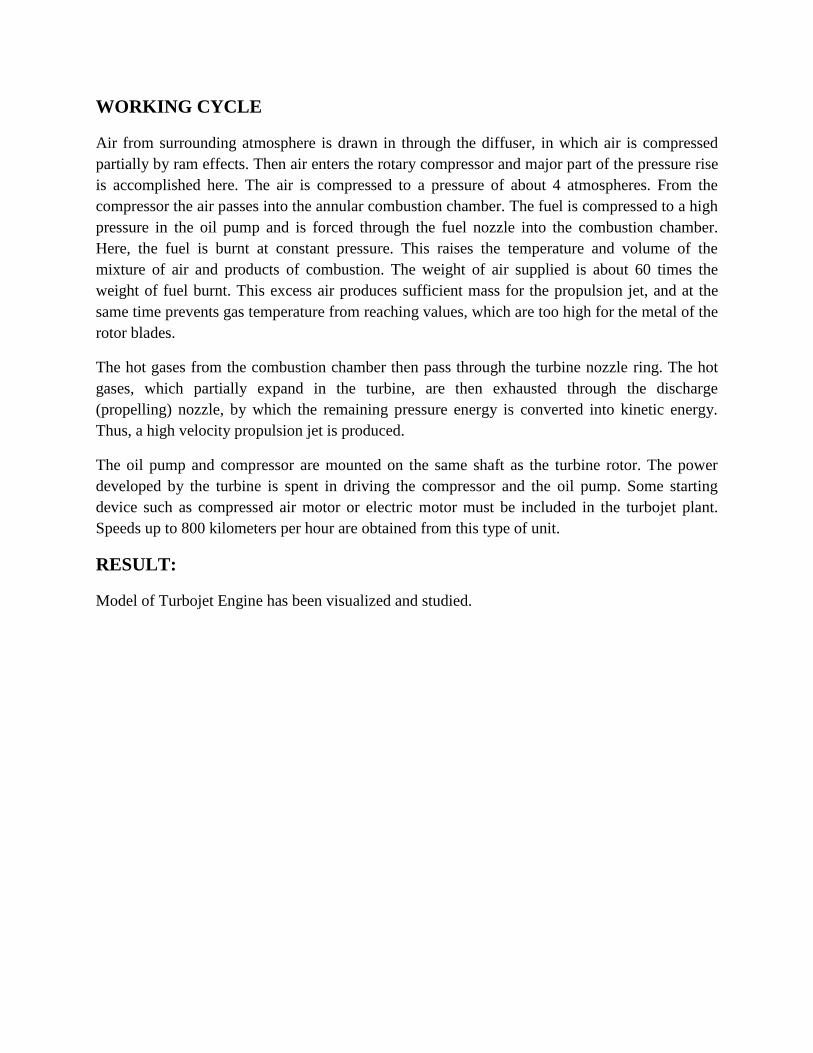
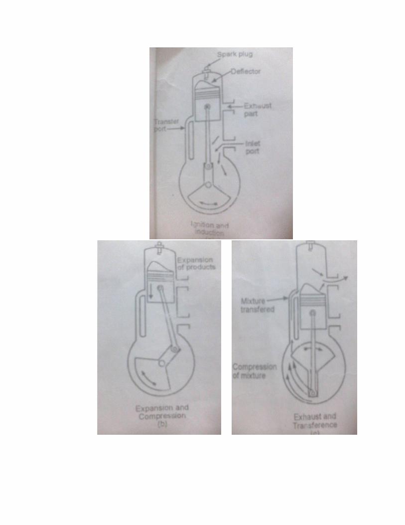
I. IGNITION OR INDUCTION:
The piston is almost at the T.D.C position when the air or mixture of air and fuel is in
compressed form. In Petrol Engine Spark occurs and ignition takes place. But in case
of Diesel Engine, the fuel is injected and combustion takes place automatically.

II. EXPANSION AND PARTIAL COMPRESSION:
Due to combustion of the charge, the pressure increases which pushes the piston
down, the expansion of gas takes place and work is done.
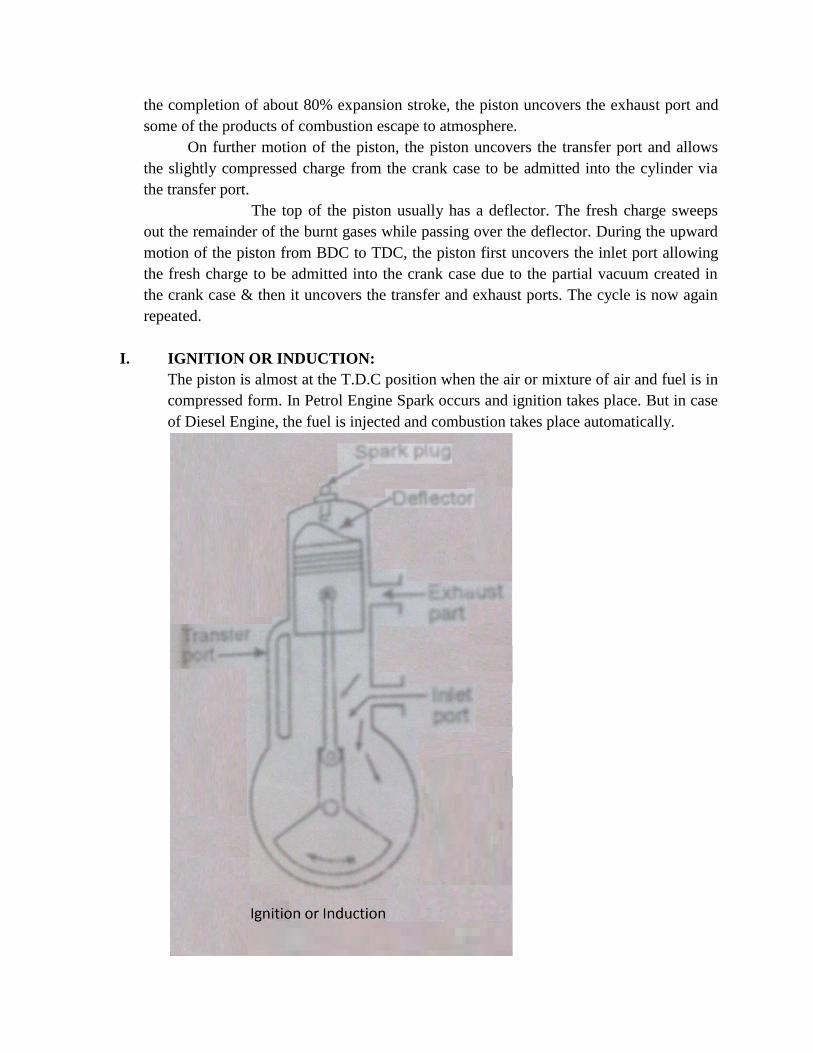
III. EXHAUST AND TRANSFERENCE:
After completing of about 4/5th
of the power, the exhaust port is uncovered by the
piston and the products of combustion starts leaving the cylinder through the exhaust
port. When the piston is approaching at the B.D.C position, the exhaust port is still
open and transfer port is uncovered by the piston. As soon as the piston reaches
B.D.C, it moves upward. In this position both inlet port and exhaust port are closed
and the compression of the charge begins in the cylinder till the piston reaches at
T.D.C. Thus during the two stroke of the piston, there is one power stroke.
APPLICATIONS:
4. I.C Engines are used in all road vehicles
5. I.C Engines are widely used in rail road, aviation, marine etc.
6. I.C Engines are extensively used in lawn movers, motor boats, concrete
mixing equipment etc.

EXPERIMENT-9
AIM- To Study and sketch about the principle of working of four stroke I.C. Engine or Petrol
Engine and Diesel Engine
INTRODUCTION:
The internal combustion engine is a heat engine in which the energy of fuel air mixture is
released by combustion in the engine cylinder itself. The heat energy increases the pressure and
temperature of the cylinder gas and subsequent expansion of the gas converts the heat energy
into mechanical work.
MAIN PARTS OF THE I.C ENGINE OR PETROL ENGINE
1) Cylinder:
It is hollow cylinder, one side of which is closed by cylinder head and is made of cast
iron. The fuel is burnt inside of the cylinder and power is developed due to reciprocating
motion of the piston. Cylinder head usually contains both the valves and fuel injector or
spark plug. The internal diameter of cylinder is called Bore.
2) Piston:
The piston is made of cylindrical casting of iron or aluminium alloy. The piston is
accurately machined to running fit in the cylinder bore and is provided with several
grooves into which piston rings are fitted. The main function of piston is to transmit the
force created by combustion products to the connecting rod.
3) Piston Rings:
The piston is made of cylindrical casting of iron or aluminium alloy. The function of the
piston rings is to prevent any leakage of gas past the piston and to prevent the wear of the
piston.
4) Connecting Rod:
The Connecting Rod connects the piston and crank pin. The function of connecting rod is
to convert the reciprocating motion of the piston into rotary motion of crankshaft. It is
made up of forged steel.
5) Crank Shaft:
The crankshaft is the principle rotating part of the engine. It serves to convert the forces
applied by the connecting rod into rotational force. It controls the motion of piston and is
made of forged alloy steel or carbon steel.
6) Valves:
There are two valves for every cylinder. One is the inlet valve which admits air or
mixture of air and fuel in the suction stroke. The other is the exhaust valve through which
the product of combustion after doing work on the piston escapes to the atmosphere.
7) Cams and Camshaft:
Each valve requires a cam to open and close it, at the proper point in engine cycle. The
cams are mounted on a shaft known as camshaft, which is driven by crank shaft through
gears.
8) Crankcase:
The crankcase holds together the cylinder, piston and crankshaft.
9) Carburetor:
It is used in petrol engines to atomize, vaporize and mixing the fuel with air in required
proportion at all loads and speed before entering to the engine cylinder.
10) Fuel Pump and Injector Unit:
It is used in diesel engine to supply the fuel under high pressure to atomizer or injector
which consists of one or more orifices through which the fuel is sprayed into cylinder.
11) Spark Plug:
It petrol engine a spark plug is located at the top of cylinder and initiates combustion.
12) Flywheel:
It is heavy wheel mounted on the crankshaft to minimize the cyclic variations in speed
the turning moment becomes uniform at the crankshaft.

WORKING OF FOUR STROKE PETROL ENGINE:
Petrol Engine operates on a four stroke cycle.
I. INTAKE OR SUCTION STROKE:
During suction stroke intake valve is opened and the exhaust valve is closed and
the piston moves down, due to rotation of crankshaft either getting energy from
the flywheel or from a motor starter. As the piston moves the pressure in the
cylinder drops below atmospheric pressure. The high pressure on carburetor or air
filter side thrust the air to rush towards cylinder. The suction process continues till
the piston moves from the top dead centre position to the bottom dead centre.

II. COMPRESSION STROKE:
During this stroke both the valve are closed and piston moves from B.D.C to
T.D.C. The air is compressed upto a compression ratio. There is reduction of
volume of air or charge which results in an increase of pressure and the
temperature of the cylinder contents. In petrol engines the compression ratio
varies from 5 to 10.5 and pressure and temperature at the end of compression are
7 to 14 bars and 250°C to 500°C respectively. For Diesel engines the compression
ratio is 12 to 20 and the pressure and temperature at the end of compression are 28
to 59 bars and 600°C to 700°C respectively.

III. EXPANSION OR POWER STROKE:
During this stroke both valves are closed. The power stroke includes combustion
of fuel and expansion of the products of the combustion. The combustion starts at
the end of the compression stroke when piston is approaching to T.D.C. In petrol
engine, a spark plug initiates the combustion. During combustion temperature and
pressure of the gas is increased. The volume of gas however remains constant
during combustion.
In Diesel Engines, one or more jets of fuel, compressed to a
pressure of 105 to 210 bar by an injector pump are injected into the combustion
chamber by a fuel nozzle at the end of compression stroke. The injected fuel is
vaporized and is raised to self ignition temperature. The combustion then starts
automatically and there is sudden rise of temperature at constant pressure. The
high pressure and the high temperature of the product of combustion, thus
obtained push the piston outward from T.D.C TO B.D.C position. This
reciprocating motion of the piston is converted into the rotary motion by
crankshaft, connecting rod and crank mechanism.
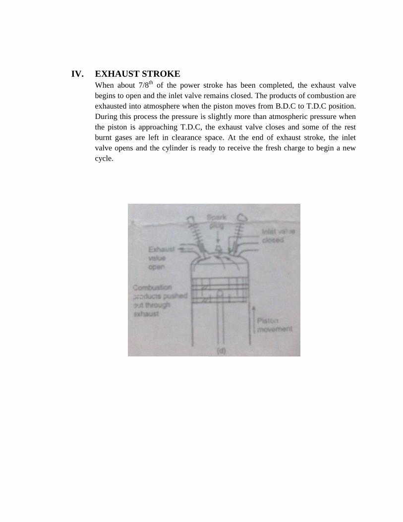
IV. EXHAUST STROKE
When about 7/8th
of the power stroke has been completed, the exhaust valve
begins to open and the inlet valve remains closed. The products of combustion are
exhausted into atmosphere when the piston moves from B.D.C to T.D.C position.
During this process the pressure is slightly more than atmospheric pressure when
the piston is approaching T.D.C, the exhaust valve closes and some of the rest
burnt gases are left in clearance space. At the end of exhaust stroke, the inlet
valve opens and the cylinder is ready to receive the fresh charge to begin a new
cycle.

APPLICATIONS:
7. I.C Engines are used in all road vehicles
8. I.C Engines are widely used in rail road, aviation, marine etc.
9. I.C Engines are extensively used in lawn movers, motor boats, concrete
mixing equipment etc.
EXPERIMENT-10
AIM- Determination of Indicated H.P of I.C Engine by MORSE TEST
INTRODUCTION-
INDICATED POWER-
Indicated power (i.p) of multi-cylinder engine is measured by MORSE TEST. It consist of
running the engine on its test bed against a dynamometer at a particular speed, cutting out the
firing of each cylinder in turn and noting the fall in Brake Power (b.p) each time while
maintaining the set engine speed. The observed difference in b.p between all cylinders firing and
with one cylinder cut out is the indicated power of the cut out cylinder. This is demonstrated as
follows:
With n cylinders and all firing
i.Pn = b.Pn + friction power ’’’’’’’’’’’’’’’’’’’’’’’’’ (1)
With one cylinder cut out
i.Pn-1 = b.Pn-1 + friction power ’’’’’’’’’’’’’’’’’’’’’’’’’ (2)
Subtracting (2) from (1) yields the indicated power of the cut out cylinder
i.Pn - i.Pn-1 = b.Pn - b.Pn-1
Thus the i.p of each cylinder in turn can be found and hence the sum of these values will give the
i.p of engine with all (n) cylinders firing.
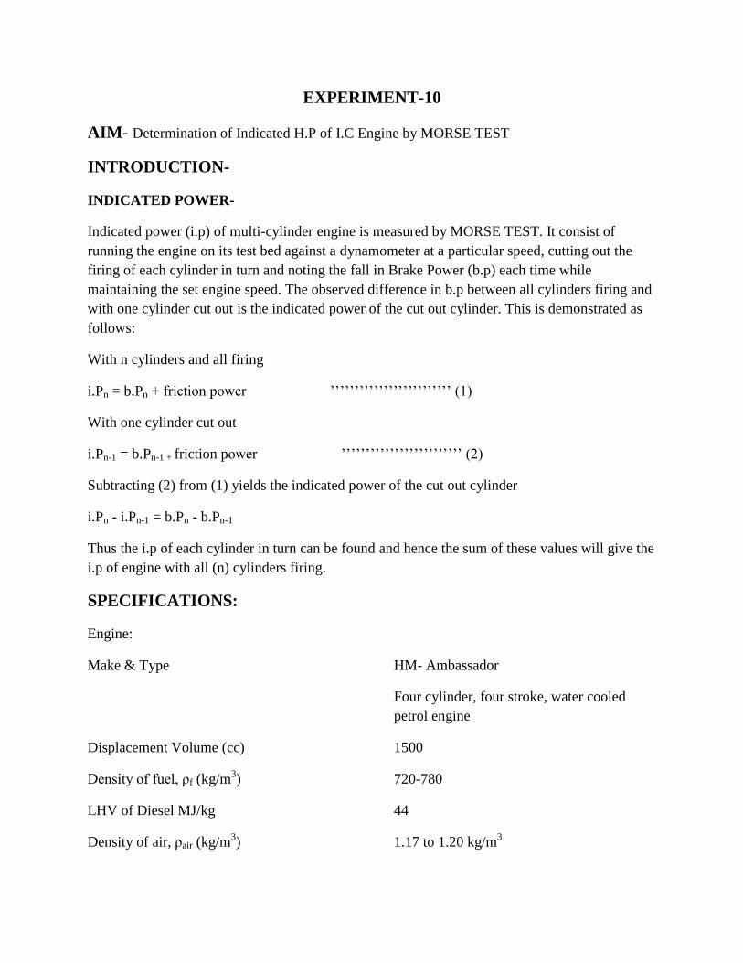
SPECIFICATIONS:
Engine:
Make & Type HM- Ambassador
Four cylinder, four stroke, water cooled
petrol engine
Displacement Volume (cc) 1500
Density of fuel, ρf (kg/m3) 720-780
LHV of Diesel MJ/kg 44
Density of air, ρair (kg/m3) 1.17 to 1.20 kg/m
3

PERFORMANCE TEST
Step 1: Open the tap to allow cooling water to circulate through the engine.
Step 2: Start the engine and allow it to run for atleast 15 minutes to attain steady state.
Step 3: Fix the throttle position so as to have certain speed. Apply the load on the engine so that
the speed of the engine is around 1500 R.P.M.
Step 4: Allow the engine to run for atleast 10 to 15 minutes to adjust to the new conditions.
Step 5: Note down:
(i) Speed of the engine,
(ii) Dynamometer load,
(iii) Time taken for consumption of 50ml of fuel,
(iv) Pressure difference, indicated by the manometer, across the orifice.
(v) Temperature of the incoming air
(vi) Inlet and outlet temperature of the cooling water
Step 6: Repeat the procedure for different load o n the engine so that the speed changes (Do
not change the throttle position) in steps of 100 RPM allowing engine to adjust at
each load change.
Step 7: Make a record of readings in the tabular form as shown and calculate various parameters.
S.No Engine
Speed
(N)
rev/mi
n
Dyna-
momet
-er
load
readin
g
Net
Load
Brake
Power
Time
for 50
ml of
fuel (t)
sec
Brake
Specifi
cation
fuel
consum
ption
Brake
Therma
l
efficien
cy
Pressur
e drop
across
orifice
∆H
Air
mass
flow
rate
Ideal
mass
flow
rate
Voul
umet
ric
effic
ienc
y