Expansion of MX-MIG process as Pure Argon Gas …conventional arc-welding shielded in an oxidizing...
9
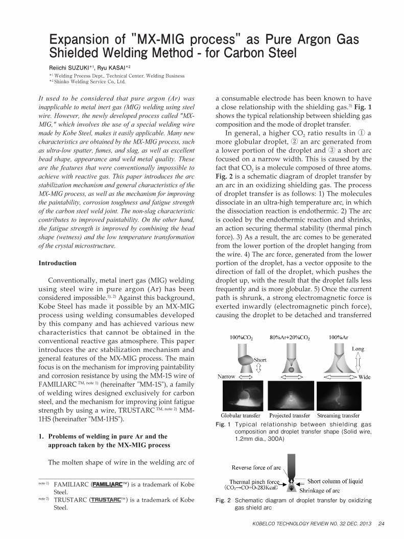
It used to be considered that pure argon (Ar) was inapplicable to metal inert gas (MIG) welding using steel wire. However, the newly developed process called "MX- MIG," which involves the use of a special welding wire made by Kobe Steel, makes it easily applicable. Many new characteristics are obtained by the MX-MIG process, such as ultra-low spatter, fumes, and slag, as well as excellent bead shape, appearance and weld metal quality. These are the features that were conventionally impossible to achieve with reactive gas. This paper introduces the arc stabilization mechanism and general characteristics of the MX-MIG process, as well as the mechanism for improving the paintability, corrosion toughness and fatigue strength of the carbon steel weld joint. The non-slag characteristic contributes to improved paintability. On the other hand, the fatigue strength is improved by combining the bead shape (wetness) and the low temperature transformation of the crystal microstructure. Introduction Conventionally, metal inert gas (MIG) welding using steel wire in pure argon (Ar) has been considered impossible. 1), 2) Against this background, Kobe Steel has made it possible by an MX-MIG process using welding consumables developed by this company and has achieved various new characteristics that cannot be obtained in the conventional reactive gas atmosphere. This paper introduces the arc stabilization mechanism and general features of the MX-MIG process. The main focus is on the mechanism for improving paintability and corrosion resistance by using the MM-1S wire of FAMILIARC TM, note 1) (hereinafter "MM-1S"), a family of welding wires designed exclusively for carbon steel, and the mechanism for improving joint fatigue strength by using a wire, TRUSTARC TM, note 2) MM- 1HS (hereinafter "MM-1HS"). 1. Problems of welding in pure Ar and the approach taken by the MX-MIG process The molten shape of wire in the welding arc of a consumable electrode has been known to have a close relationship with the shielding gas. 3) Fig. 1 shows the typical relationship between shielding gas composition and the mode of droplet transfer. In general, a higher CO 2 ratio results in ① a more globular droplet, ② an arc generated from a lower portion of the droplet and ③ a short arc focused on a narrow width. This is caused by the fact that CO 2 is a molecule composed of three atoms. Fig. 2 is a schematic diagram of droplet transfer by an arc in an oxidizing shielding gas. The process of droplet transfer is as follows: 1) The molecules dissociate in an ultra-high temperature arc, in which the dissociation reaction is endothermic. 2) The arc is cooled by the endothermic reaction and shrinks, an action securing thermal stability (thermal pinch force). 3) As a result, the arc comes to be generated from the lower portion of the droplet hanging from the wire. 4) The arc force, generated from the lower portion of the droplet, has a vector opposite to the direction of fall of the droplet, which pushes the droplet up, with the result that the droplet falls less frequently and is more globular. 5) Once the current path is shrunk, a strong electromagnetic force is exerted inwardly (electromagnetic pinch force), causing the droplet to be detached and transferred Expansion of "MX-MIG process" as Pure Argon Gas Shielded Welding Method - for Carbon Steel Reiichi SUZUKI *1 , Ryu KASAI *2 *1 Welding Process Dept., Technical Center, Welding Business *2 Shinko Welding Service Co., Ltd. note 1) FAMILIARC ( ) is a trademark of Kobe Steel. note 2) TRUSTARC ( ) is a trademark of Kobe Steel. Fig. 2 Schematic diagram of droplet transfer by oxidizing gas shield arc Fig. 1 Typical relationship between shielding gas composition and droplet transfer shape (Solid wire, 1.2mm dia., 300A) KOBELCO TECHNOLOGY REVIEW NO. 32 DEC. 2013 24
Transcript of Expansion of MX-MIG process as Pure Argon Gas …conventional arc-welding shielded in an oxidizing...
It used to be considered that pure argon (Ar) was inapplicable to metal inert gas (MIG) welding using steel wire. However, the newly developed process called "MX-MIG," which involves the use of a special welding wire made by Kobe Steel, makes it easily applicable. Many new characteristics are obtained by the MX-MIG process, such as ultra-low spatter, fumes, and slag, as well as excellent bead shape, appearance and weld metal quality. These are the features that were conventionally impossible to achieve with reactive gas. This paper introduces the arc stabilization mechanism and general characteristics of the MX-MIG process, as well as the mechanism for improving the paintability, corrosion toughness and fatigue strength of the carbon steel weld joint. The non-slag characteristic contributes to improved paintability. On the other hand, the fatigue strength is improved by combining the bead shape (wetness) and the low temperature transformation of the crystal microstructure.
Introduction
Conventionally, metal inert gas (MIG) welding using steel wire in pure argon (Ar) has been considered impossible.1), 2) Against this background, Kobe Steel has made it possible by an MX-MIG process using welding consumables developed by this company and has achieved various new characteristics that cannot be obtained in the conventional reactive gas atmosphere. This paper introduces the arc stabilization mechanism and general features of the MX-MIG process. The main focus is on the mechanism for improving paintability and corrosion resistance by using the MM-1S wire of FAMILIARC TM, note 1) (hereinafter "MM-1S"), a family of welding wires designed exclusively for carbon steel, and the mechanism for improving joint fatigue strength by using a wire, TRUSTARC TM, note 2) MM-1HS (hereinafter "MM-1HS").
1. Problems of welding in pure Ar and the approach taken by the MX-MIG process
The molten shape of wire in the welding arc of
a consumable electrode has been known to have a close relationship with the shielding gas.3) Fig. 1 shows the typical relationship between shielding gas composition and the mode of droplet transfer. In general, a higher CO2 ratio results in ① a more globular droplet, ② an arc generated from a lower portion of the droplet and ③ a short arc focused on a narrow width. This is caused by the fact that CO2 is a molecule composed of three atoms. Fig. 2 is a schematic diagram of droplet transfer by an arc in an oxidizing shielding gas. The process of droplet transfer is as follows: 1) The molecules dissociate in an ultra-high temperature arc, in which the dissociation reaction is endothermic. 2) The arc is cooled by the endothermic reaction and shrinks, an action securing thermal stability (thermal pinch force). 3) As a result, the arc comes to be generated from the lower portion of the droplet hanging from the wire. 4) The arc force, generated from the lower portion of the droplet, has a vector opposite to the direction of fall of the droplet, which pushes the droplet up, with the result that the droplet falls less frequently and is more globular. 5) Once the current path is shrunk, a strong electromagnetic force is exerted inwardly (electromagnetic pinch force), causing the droplet to be detached and transferred
Expansion of "MX-MIG process" as Pure Argon Gas Shielded Welding Method - for Carbon SteelReiichi SUZUKI*1, Ryu KASAI*2
*1 Welding Process Dept., Technical Center, Welding Business*2 Shinko Welding Service Co., Ltd.
note 1) FAMILIARC ( ) is a trademark of Kobe Steel.
note 2) TRUSTARC ( ) is a trademark of Kobe Steel.
Fig. 2 Schematicdiagramofdroplet transferbyoxidizinggasshieldarc
Fig. 1 Typical relationship between shielding gascompositionanddroplet transfershape(Solidwire,1.2mmdia.,300A)
KOBELCO TECHNOLOGY REVIEW NO. 32 DEC. 2013 24

straight downward, while keeping its globular shape. The above process is repeated for the stable melting and transfer of the wire. In contrast to this, a monoatomic molecule gas such as Ar does not dissociate in the arc, causing neither an endothermic reaction nor a thermal pinch force. As a result, the arc is generated from a large portion of the wire, including its upper part, and melts the wire. On the other hand, the wide current path can create only a weak electromagnetic pinch force not capable of cutting and detaching the molten wire. This causes the formation of an excessively long liquid column, or the phenomenon called a "streaming transfer". This makes the arc unstable, with its molten portion at the wire tip swinging and whipping (Fig. 3). The resulting weld exhibits a meandering bead, which is called a "wandering phenomenon". The reason for the long massive liquid column in the Ar gas shielded arc is that a solid wire, having a homogeneous cross-section, starts to melt at the same time throughout almost its entire cross-section.4) To resolve this problem, a two-step melting was devised, in which the periphery melts earlier than the center does, such that the solid in the center works as a stable column that prevents the droplet from being affected by a meandering arc. To achieve this, a flux cored wire (hereinafter, FCW) was adapted. The FCW, hitherto unavailable and exclusively designed by Kobe Steel, is combined with pure Ar gas to create a new process, named the "MX-MIG process". The cross-sectional shape of the FCW is separated into a metal hoop on the periphery and flux in the center. Because most electric current passes through the metal hoop, the flux portion is not directly heated when energized. Therefore, the peripheral hoop melts first, and the inner flux disintegrates, falls and is transferred into the molten pool along with the molten droplet of the hoop. Because the droplet is not formed by melting throughout the entire cross-section, the molten portion at the wire tip does not crawl up, even if the arc crawls up in the gas shield of pure Ar, which maintains the globular-shaped droplet transfer (Fig. 4). Combination with a pulse power source having a high peak current
improves the regularity of the droplet transfer, stabilizing the arc in a low current region. It should be noted that not all types of FCWs can achieve normal droplet transfer. Each FCW for MX-MIG is designed such that its composition, hoop/flux ratio and the like are adjusted to achieve the optimum characteristics. This measure for stabilizing the droplet transfer has enabled the MX-MIG process to produce a weld-metal shape that is superior to that obtained by conventional arc-welding shielded in an oxidizing gas 5) - 8) (Fig. 5).
2. Welding quality features of MX-MIG process
Notwithstanding its arc shape that is unique to pure Ar shielding gas, the MX-MIG process has achieved the epoch-making function of significantly stabilizing the droplet transfer, thanks to the design as described in section 1. The arc, unique to the MX-MIG process, has brought about various improvements in the welding quality. The following are the common effects of the process: ①Low spatter: Spatter is due to the counterforce of the arc force. In MX-MIG, the arc area is extended, which suppresses the arc force and leads to an extremely low amount of spattering. ②Low fume: Fume is caused by the evaporation of the metal that is exposed to an ultra-high temperature in the vicinity of the arc anode point. In MX-MIG, the generation of the arc at the wire tip is dispersed, which decreases the arc density and arc temperature, suppressing the fume. This also reduces the amount of hazardous materials, such as hexavalent chromium, that can
Fig. 3 Schematic diagram of droplet t ransfer byconventionalargongasshieldarc
Fig. 5 Examplesofbeadappearance,comparingMX-MIGexclusiveFCWandconventionalwire, for argongasshieldarc
Fig. 4 Schematicdiagramofdroplet transferbyMX-MIGprocesscombining special flux coredwirewithargongasshieldarc
KOBELCO TECHNOLOGY REVIEW NO. 32 DEC. 201325
cause problems in the welding of stainless steel. ③Slag-free/Low slag: Slag is a compound, formed of elements such as Si, Mn and Ti, which are oxidized in a molten pool. MX-MIG, which uses pure Ar for its shielding gas, is oxygen free and in principle can minimize the generation of slag. ④Less likelihood of being diluted by the base material: MX-MIG has a wide arc area with decreased arc force per unit area, which results in a shallow melting depth. The process is preferable for welding such as overlaying, in which the influence of the base material should be avoided to achieve good weld metal quality. ⑤Clean appearance and shape of the weld bead: The suppressed arc force and extended arc area widen the bead shape, enabling the production of bead shapes with excellent wetting. Welding defects, such as undercut defects, caused by excessive arc force, are less likely to occur. The use of pure Ar gas renders the oxidization of the bead surface unlikely and enables the production of glossy surfaces. ⑥High-speed, high-efficiency: The speeding up of welding generally results in an increased arc force, which increases fluidity and makes the bead more likely to be convex in shape. This also causes so-called "weld-bead humping", a phenomenon in which a bead breaks up. The suppressed arc-force of MX-MIG decreases the fluidity, realizing excellent bead shapes during high-speed welding. ⑦High-quality weld metal: An increased amount of oxygen in steel can cause embrittlement. In the case of stainless steel, an increased amount of carbon lowers the corrosion resistance. MX-MIG uses no CO2 in its shielding gas, and neither C nor O is dissociated in the arc and transferred into the weld metal, which makes the weld metal very clean. To achieve these epoch-making features of the MX-MIG process, various welding wires have been developed exclusively for various steel types and applications. The following sections introduce two types of welding consumables designed for carbon steel.
3. Welding wire MM-1S, for general carbon steel, to improve paintability and corrosion resistance
MM-1S is an exclusive welding wire that, in particular, exploits the slag-free feature found among the various effects unique to the MX-MIG process described in section 2.9) - 11)
3.1 Developmental background
Fig. 6 shows an arc-welded portion of an automotive suspension part at the stage of shipment. Despite the post welding corrosion protection
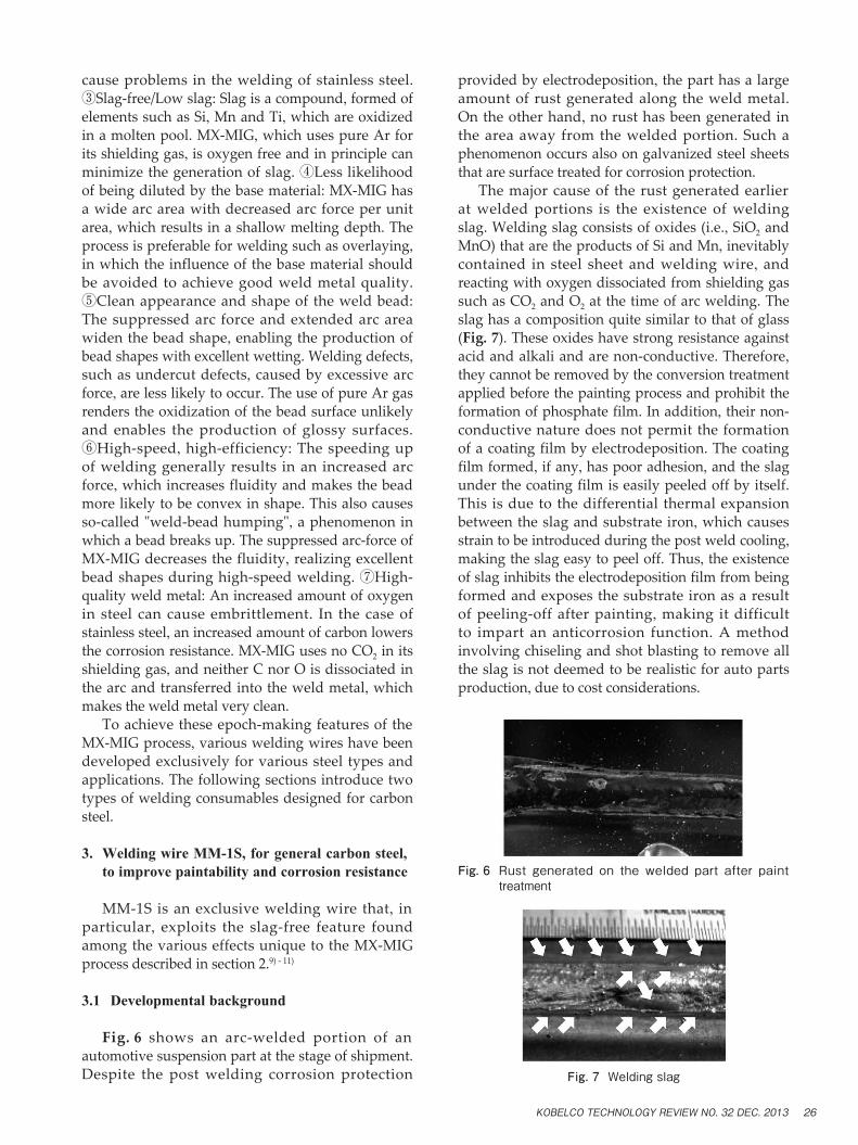
provided by electrodeposition, the part has a large amount of rust generated along the weld metal. On the other hand, no rust has been generated in the area away from the welded portion. Such a phenomenon occurs also on galvanized steel sheets that are surface treated for corrosion protection. The major cause of the rust generated earlier at welded portions is the existence of welding slag. Welding slag consists of oxides (i.e., SiO2 and MnO) that are the products of Si and Mn, inevitably contained in steel sheet and welding wire, and reacting with oxygen dissociated from shielding gas such as CO2 and O2 at the time of arc welding. The slag has a composition quite similar to that of glass (Fig. 7). These oxides have strong resistance against acid and alkali and are non-conductive. Therefore, they cannot be removed by the conversion treatment applied before the painting process and prohibit the formation of phosphate film. In addition, their non-conductive nature does not permit the formation of a coating film by electrodeposition. The coating film formed, if any, has poor adhesion, and the slag under the coating film is easily peeled off by itself. This is due to the differential thermal expansion between the slag and substrate iron, which causes strain to be introduced during the post weld cooling, making the slag easy to peel off. Thus, the existence of slag inhibits the electrodeposition film from being formed and exposes the substrate iron as a result of peeling-off after painting, making it difficult to impart an anticorrosion function. A method involving chiseling and shot blasting to remove all the slag is not deemed to be realistic for auto parts production, due to cost considerations.
Fig. 7Weldingslag
Fig. 6 Rust generated on thewelded part after painttreatment
KOBELCO TECHNOLOGY REVIEW NO. 32 DEC. 2013 26

Meanwhile, galvanization does not provide the welding joint with any anticorrosion function, because the boiling point of zinc is as low as 906℃12), and the ultra-high temperature arc-heat evaporates the zinc. This disables plating beyond the width of the weld metal. It is reported that a sacrificial protection works in the periphery of galvanization13), 14); however, its working distance is too small to cover the entire width of the coating lost by the arc-heat. Thus the use of galvanized steel sheet would accomplish nothing, as far as the welded portion is concerned. Therefore, there has been a need for a more effective approach to prevent rust formation at welded portions.
3.2 Mechanism and effect of improving paintability/ corrosion resistance
A welded portion must be slag-free for a coating film to form on it. Reducing the slag sources, such as Si and Mn, to zero is not an effective solution because this may oxidize the iron itself, which increases porosity defects and impairs the basic characteristics of the steel. This leaves only one option: that is, to make the oxidizing power of the shielding gas zero so as to inhibit the oxidation reaction of droplets during the arc transfer and in the molten pool. This virtually equates with implementing a shielding gas of pure Ar. Because MIG welding using steel wire in pure Ar has conventionally been considered impossible, there has hitherto been no such practical application of this idea. However, the development of the MX-MIG process, as described above, has enabled the implementation of MIG welding in pure Ar. MM-1S is a wire particularly designed for the most effective exploitation of its slag-free effect. An example of the appearance of the bead produced by this wire is shown in Fig. 8. As shown, the bead of MM-1S has almost no slag formed on it and appears clean. Fig. 9 compares the bead appearance of the conventional MAG weld made using a general purpose solid wire with that of a weld made using MM-1S. Both welds were made on an actual auto
part. The conventional method resulted in slag being formed along the side and at the center of the bead, while MM-1S resulted in no slag formation. The MM-1S and conventional welding methods / consumables were compared as to their paintability and corrosion resistance. The results are shown in Fig.10. After the electrodeposition, both the CO2 welding and Ar + CO2 mixed gas welding, using conventional welding consumables, resulted in painting defects at locations such as the edge of the bead. This sample was subjected as-is to a corrosion test, including repeated cycles of salt water spraying, drying and wetting. In the case of the conventional welding, the rust generation from the edge of the bead becomes evident as the number of cycle increases. Now two things are known regarding the conventional welding method. The first is that, although Ar + CO2 mixed gas is reported to generate a smaller amount of slag compared with CO2 gas, the two are comparable in terms of rust inhibition. This is considered to indicate that the amount of rust is not in a linear relationship with the number of origins of the rust, and a minute number of origins can cause a significant deterioration. The second is that, even if the steel sheet is galvanized, that does not have much effect on the rust inhibition of the welded portion, as described above. In the early stage (at a low cycle number) of the corrosion test, the galvanized steel exhibits a slightly smaller amount of rust, an indication of sacrificial protection; however, the galvanized steel becomes almost comparable to the general steel as the cycle extends to a long term. Meanwhile, the propagation of rust in the direction away from the bead seems to be slightly suppressed. On the other hand, the Ar gas shielded welding using MM-1S allows almost perfect electrodeposition, which results in almost no rust after a long term corrosion condition of 150 cycles. There has been no measure available to inhibit automotive parts from rusting after welding and thus to improve the paintability. The improvement needs are satisfied by adopting the MX-MIG process using MM-1S as a welding consumable. This can prevent rusting in a less costly and more effective
Fig. 9 Slag-freeeffectofFAMILIARCMM-1S inactualparts
Fig. 8BeadappearanceusingFAMILIARCMM-1S
Weldingcondition;100%Arshieldinggas,Pulsepowersource,220Acurrent,100cm/mintravelspeed,Lapjointofmildsteel2.3mmthickness
KOBELCO TECHNOLOGY REVIEW NO. 32 DEC. 201327

manner than would the adoption of galvanized steel sheet, which can incur higher cost.
4. MM-1HS, welding wire to improve joint fatigue strength in high-tensile steel
MM-1HS is an exclusive welding wire particularly exploiting the bead shape improvement effect and the non-entry of oxygen from the shielding gas into the arc atmosphere, among the various effects unique to the MX-MIG process as described in section 2.15) - 24)
4.1 Developmental background
Recently, automotive weight reduction has been increasingly needed to further improve fuel economy and thus to reduce CO2 emissions. Attempts have been made to thin the parts by using high-tensile-strength steel sheets. However, although the strength of the steel sheet has been increased, the fatigue characteristics of the welded joints have not been much improved, due to their
nature (Fig.11). This is the main factor inhibiting the use of high-tensile-strength steel for suspension parts, due to the importance of their fatigue characteristics. It has been said that there are two reasons why the fatigue characteristics of welded joint do not improve. The first is the stress concentration at the weld toe, or a shape factor. The second is the tensile residual stress in the periphery of weld toes, or a thermal factor. Whether the stress concentration or residual stress contributes more to fatigue strength reduction is considered to depend on the sheet thickness and joint properties. Regardless of the difference in the contribution ratio, at least one of the two, either the shape or the residual stress, must be improved in order to increase the fatigue strength of a welded joint. Techniques for improving the shape of a weld toe, more specifically, techniques for increasing the weld toe radius ρ and/or weld toe angle θ, include mechanical grinding and re-melting of the weld toe after welding; however, there has been no more efficient measure than this. In order to improve
Fig.10Resultsofpaintabilityandcorrosiontestusingseveralweldingmethods,wires,andshieldinggasesincombination
Weldingcondition; 2.3or2.9mmthickness,lapjoint,100cm/mintravelspeedChemicaltreatmentcondition; Dippingphosphateprocesssolution,target2g/m2quantityElectrodepositionpaintcoatcondition; Cationtype,target25μmthicknessCorrosiontestcondition; JASO-CCTstandard8h/cycle 1cycle:5%saltwatermist(35degreesCelsius・2h)→Drying(60degreesCelsius・25%RH・4h) →Wetting(50degreesCelsius・98%RH・2h)
KOBELCO TECHNOLOGY REVIEW NO. 32 DEC. 2013 28
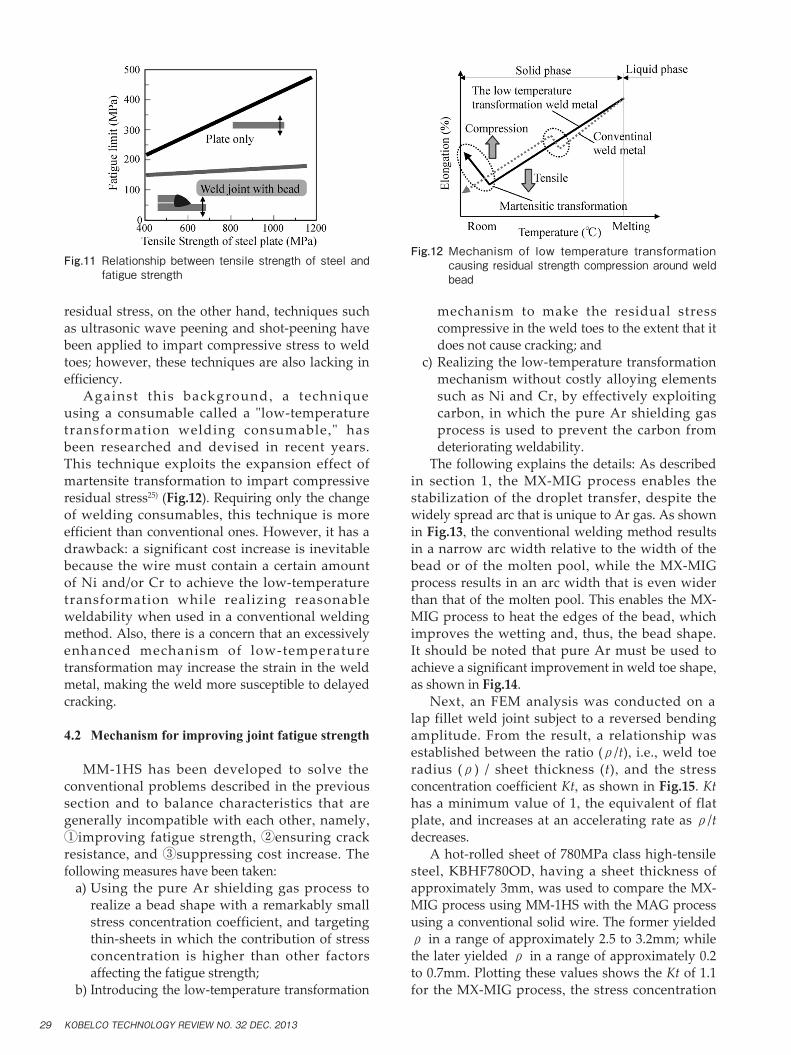
residual stress, on the other hand, techniques such as ultrasonic wave peening and shot-peening have been applied to impart compressive stress to weld toes; however, these techniques are also lacking in efficiency. Against this background , a technique using a consumable called a "low-temperature transformation welding consumable ," has been researched and devised in recent years. This technique exploits the expansion effect of martensite transformation to impart compressive residual stress25) (Fig.12). Requiring only the change of welding consumables, this technique is more efficient than conventional ones. However, it has a drawback: a significant cost increase is inevitable because the wire must contain a certain amount of Ni and/or Cr to achieve the low-temperature transformation while realizing reasonable weldability when used in a conventional welding method. Also, there is a concern that an excessively enhanced mechanism of low-temperature transformation may increase the strain in the weld metal, making the weld more susceptible to delayed cracking.
4.2 Mechanism for improving joint fatigue strength
MM-1HS has been developed to solve the conventional problems described in the previous section and to balance characteristics that are generally incompatible with each other, namely, ①improving fatigue strength, ②ensuring crack resistance, and ③suppressing cost increase. The following measures have been taken: a) Using the pure Ar shielding gas process to
realize a bead shape with a remarkably small stress concentration coefficient, and targeting thin-sheets in which the contribution of stress concentration is higher than other factors affecting the fatigue strength;
b) Introducing the low-temperature transformation
mechanism to make the residual stress compressive in the weld toes to the extent that it does not cause cracking; and
c) Realizing the low-temperature transformation mechanism without costly alloying elements such as Ni and Cr, by effectively exploiting carbon, in which the pure Ar shielding gas process is used to prevent the carbon from deteriorating weldability.
The following explains the details: As described in section 1, the MX-MIG process enables the stabilization of the droplet transfer, despite the widely spread arc that is unique to Ar gas. As shown in Fig.13, the conventional welding method results in a narrow arc width relative to the width of the bead or of the molten pool, while the MX-MIG process results in an arc width that is even wider than that of the molten pool. This enables the MX-MIG process to heat the edges of the bead, which improves the wetting and, thus, the bead shape. It should be noted that pure Ar must be used to achieve a significant improvement in weld toe shape, as shown in Fig.14. Next, an FEM analysis was conducted on a lap fillet weld joint subject to a reversed bending amplitude. From the result, a relationship was established between the ratio (ρ/t), i.e., weld toe radius (ρ) / sheet thickness (t), and the stress concentration coefficient Kt, as shown in Fig.15. Kt has a minimum value of 1, the equivalent of flat plate, and increases at an accelerating rate as ρ/t decreases. A hot-rolled sheet of 780MPa class high-tensile steel, KBHF780OD, having a sheet thickness of approximately 3mm, was used to compare the MX-MIG process using MM-1HS with the MAG process using a conventional solid wire. The former yielded ρ in a range of approximately 2.5 to 3.2mm; while the later yielded ρ in a range of approximately 0.2 to 0.7mm. Plotting these values shows the Kt of 1.1 for the MX-MIG process, the stress concentration
Fig.11 Relationshipbetween tensilestrengthofsteelandfatiguestrength
Fig.12 Mechanism of low temperature transformationcausingresidualstrengthcompressionaroundweldbead
KOBELCO TECHNOLOGY REVIEW NO. 32 DEC. 201329

that is close to that of a flat plate, and a higher value of approximately 1.5 - 2.0 for the conventional MAG process. In other words, MM-1HS results in a stress concentration, the primary factor in decreasing fatigue strength, that is more relaxed compared with that of the conventional process. Now, we consider tensile residual stress, another factor decreasing the joint fatigue strength.
Martensite transformation is known as a solid phase transformation accompanying expansion; and the starting temperature of a martensite transformation (hereinafter, Ms) is reported to be expressed, for example, as follows: Ms(℃)=561-474C-33Mn-17Cr-17Ni-21Mo … (1) 26)
Ms(℃)=550-361C-39Mn-35V-20Cr-17Ni-10Cu -5(Mo+W)+15Co+30Al ……………… (2) 27)
During the cooling process of weld metal, either a ferrite transformation or a martensite transformation occurs, depending on the cooling rate. In accordance with the above Ms point equations, the Ms point lowers with an increasing additive amount of C, Mn, Cr, Ni and Mo. Among these elements, Ni, with its advantage of being less susceptible to the cooling rate, is known to be the element that is most effective in causing martensite transformation; however, Ni is very costly. Therefore, the present development proactively exploits C, which has a large coefficient in the Ms point equations. Being known as an element that causes spatter and fume, C is generally avoided in welding consumables. However, the cause of the deterioration in welding workability associated with the C addition is the gaseous explosion caused by the reaction of oxygen, dissociated from the shielding gas containing CO2 and O2, with C in the wire.28) The MX-MIG process, on the other hand, has no oxygen in the shielding gas and causes hardly any explosion, which enables the use of wire containing an increased amount of C without causing deterioration in welding workability. Thus the component factor unique to the MX-MIG process permits the proactive use of an inexpensive element that had hitherto been unexploitable. MM-1HS that was developed has a composition optimally designed for arc stabilization in the MX-MIG process, as well as for low-temperature transformation. FEM analyses were conducted on lap fillet weld joints of 780MPa class steel sheets prepared by conventional welding and by using MM-1HS. The resultant distribution of residual stress in the cross-section of each welded portion is shown in Fig.16. Comparing the weld toes (circled areas), where the degree of stress concentration becomes high, the joint made by MM-1HS is found to have stronger compressive residual stress. Fig.17 shows the residual stress near the surfaces of actual welded joints, measured by an X-ray residual stress measurement apparatus. MM-1HS exhibits strong compressive stress in the vicinity of the base/weld interface, supporting the analysis results shown in Fig.16. As described above, MM-1HS is used with a
Fig.14 Relationshipwithargonmixingrateinshieldinggasandtoeradiusofthebead
Fig.13 Comparisonof arc,moltenpool andbeadcrossshapewidth inMX-MIGprocessandconventionalwelding process (Welding conditions; current:200A,weldingrate:1,000mm/min,arcvoltage)
Fig.15 Relationship between toe radius and stressconcentrationcoefficientKt
KOBELCO TECHNOLOGY REVIEW NO. 32 DEC. 2013 30
shielding gas of pure Ar, which has conventionally been inapplicable, to realize an epoch-making technique for simultaneously improving two issues with weld toes, namely, ①relaxing stress concentration and ②making the residual stress compressive.
4.3 Joint fatigue strength improvement effect
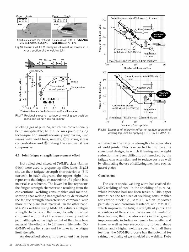
Hot rolled steel sheets of 780MPa class (3.4mm thick) were used to prepare lap fillet joints. Fig.18 shows their fatigue strength characteristics (S-N curves). In each diagram, the upper right line represents the fatigue characteristic of a plane base material as a reference. The lower left line represents the fatigue strength characteristic resulting from the conventional welding consumables and method, showing that welding has significantly deteriorated the fatigue strength characteristics compared with those of the plane base material. On the other hand, MX-MIG welding using MM-1HS exhibits a fatigue strength characteristic that is significantly improved compared with that of the conventionally welded joint, although not as high as that of the plane base material. The effect is 3 to 6.2 times in life under 350-400MPa of applied stress and 1.6 times in the fatigue limit strength. As described above, improvement has been
achieved in the fatigue strength characteristics of weld joints. This is expected to improve the structural design, in which thinning and weight reduction has been difficult, bottlenecked by the fatigue characteristics, and to reduce costs as well by eliminating the use of stiffening members such as gusset plates.
Conclusions
The use of special welding wires has enabled the MIG welding of steel in the shielding of pure Ar, which hitherto had not been feasible. This paper introduces the features of welding consumables for carbon steel; i.e., MM-1S, which improves paintability and corrosion resistance, and MM-1HS, which improves the fatigue strength of joints. The advantages of these consumables are not limited to these features; their use also results in other general improvements, including extremely low spatter and fume, as well as less susceptibility to bead shape failure, and a higher welding speed. With all these features, the MX-MIG process has the potential for raising the quality of gas shielded arc welding. Kobe
Fig.17 Residualstressonsurfaceofwelding toeposition,measuredusingX-rayequipment
Fig.16 Results ofFEManalysis of residual stress in acrosssectionoftheweldingjoint
Fig.18 ExamplesofimprovingeffectonfatiguestrengthofweldinglapjointbyapplyingTRUSTARCMM-1HS
KOBELCO TECHNOLOGY REVIEW NO. 32 DEC. 201331

Steel will strive to exploit the undeveloped features of inert atmosphere and to make new proposals.
References
1) F. Matsuda et al. Journal of the Japan Welding Society. 1983, 52.
2) K. Ando et al. Welding Arc Phenomena. Sanpo Publications Inc., p. 257-268.
3) YOSETSU, YOSETSU GIJUTSU NYUMON, Sanpo Publications Inc., p.22.
4) K. Taira. Welding technology. Sanpo Publications Inc., Feb. 2006, p.64.
5) R. Suzuki. Journal of the Japan Welding Society, 2010, Vol.79, No.6, p.27.
6) Y. Umehara et al. Preprints of the National Meeting of JWS. 2008, Vol.81, No.231.
7) Y. Umehara et al. No.205 Technical commission on Welding process, Japan Welding Society.
8) Kasai et al. IIW Doc.212-1149-09, XII-1970-09, IV984-09, 2009.
9) R. Kasai et al. Preprints of the National Meeting of JWS. 2012, Vol.90, No.88.
10) R. Suzuki. Welding technology. Sanpo Publications Inc., June 2012, pp.52-59.
11) R. Suzuki. Kobe Steel Ltd. Home Page. Technical Report, Vol.522012-7, http://www.gijutsugaido.jp/catalog/2012/pageview.html#page_num=36, (accessed 2012-11-07).
12) Metals Data Book, ed. by Japan Inst. Metals13) K. Ando. The 27th Steel Technology Seminar Test, Lecture 11
Surface Treatment, Iron and Steel Institute of Japan.
14) Iron and Steel Institute of Japan. The 186th and 187th NISHIYAMA KINENGIJUTUKOZA, 2005.
15) Y. Umehara et al. Preprints of the National Meeting of JWS. 2008, Vol.81, No.232.
16) R. Kasai et al. Japan Welding Society No.197 Technical commission on Welding Metallurgy, Japan Welding Society.
17) R. Kasai. Kobe Steel Ltd. Home Page. Technical Report, Vol.512011-4, http://www.gijutsugaido.jp/catalog/techreport/pageview.html#page_num=386, (accessed 2012-11-07).
18) R. Suzuki et al. Welding technology. Sanpo Publications Inc., March 2010, p.74.
19) R. Kasai. JWES Technical commission on brazing, Joining of Advanced materials, July 2011.
20) M. Kinebuchi. No.89 Technical commission on Joining and materials Processing for Light Structures, Japan Welding Society MP-482 2010.
21) M. Kinebuchi. Chemical Plant Welding Research Committee, Japan Welding Engineering Society 6.19. 2012.
22) M. Kinebuchi. JSAE Annual Congress (Autumn) 2011.23) M. Kinebuchi. M&M Strength of materials Conference, The
Japan Society of Mechanical Engineers. 201124) M. Kinebuchi. 60th Conference, The Society of Materials
Science, Japan, 2011.25) N. Hayakawa. Welding technology. Sanpo Publications Inc.,
June 2004, p.87.26) S. Haynes. Journal of the Iron and Steel Institute, August.
1956, p.349-359.27) The Japan Institute of Metals and Materials. KOZA,
GENDAINO-KINZOKUGAKU-ZAIRYOUHEN Vol.4. Maruzen.
28) K. Ando et al. Welding Arc Phenomena. Sanpo Publications Inc., p.210-218.
KOBELCO TECHNOLOGY REVIEW NO. 32 DEC. 2013 32