Existing PVT systems and solutions - IEA SHC
130
IEA SHC TASK 60 | PVT SYSTEMS Existing PVT systems and solutions
Transcript of Existing PVT systems and solutions - IEA SHC

IEA SHC TASK 60 | PVT SYSTEMS
Existing PVT systems and solutions
Existing PVT systems and solutions
SHC Task 60/Report A1
Editor: Thomas Ramschak (AEE INTEC)
Authors (in alphabetical order):
Aleksis Baggenstos (SPF)
Alexander Mellor (Naked Energy)
Antonio Gagliano (UNICT)
Carsten Corino (Sunoyster)
Daniel Zenhäusern (SPF)
Diogo Cabral (Solarus)
Glen Ryan (Sunovate)
Isabel Guedea (EndeF)
Laetitia Brottier (DualSun)
Uli Ruoff (RUOFF energietechnik GmbH)
Maike Schubert (ZHAW)
Manuel Lämmle (Fraunhofer ISE)
Marco Pellegrini (UNIBO)
Mark Dannemand (DTU)
Marta Cañada (Abora Solar)
Niels Radisch (Ramboll)
Nikola Pokorny (UCEEB CTU)
Thomas Ramschak (AEE INTEC)
Date: May 1st, 2020
Report number, DOI 10.18777/ieashc-task60-2020-0001
Cover Photo credit: Endef
The contents of this report do not necessarily reflect the viewpoints or policies of the International Energy Agency (IEA) or its member countries, the IEA Solar Heating and Cooling Technology Collaboration Programme (SHC TCP) members or the participating researchers.

IEA Solar Heating and Cooling Technology Collaboration Programme (IEA SHC)
The Solar Heating and Cooling Technology Collaboration Programme was founded in 1977 as one of the first multilateral technology initiatives ("Implementing Agreements") of the International Energy Agency. Its mission is
“To enhance collective knowledge and application of solar heating and cooling through international collaboration to reach the goal set in the vision of solar thermal energy meeting 50% of low temperature heating and cooling
demand by 2050.”
The members of the IEA SHC collaborate on projects (referred to as Tasks) in the field of research, development, demonstration (RD&D), and test methods for solar thermal energy and solar buildings.
Research topics and the associated Tasks in parenthesis include:
• Solar Space Heating and Water Heating (Tasks 14, 19, 26, 44, 54)
• Solar Cooling (Tasks 25, 38, 48, 53)
• Solar Heat for Industrial or Agricultural Processes (Tasks 29, 33, 49, 62, 64)
• Solar District Heating (Tasks 7, 45, 55)
• Solar Buildings/Architecture/Urban Planning (Tasks 8, 11, 12, 13, 20, 22, 23, 28, 37, 40, 41, 47, 51, 52, 56,
59, 63)
• Solar Thermal & PV (Tasks 16, 35, 60)
• Daylighting/Lighting (Tasks 21, 31, 50, 61)
• Materials/Components for Solar Heating and Cooling (Tasks 2, 3, 6, 10, 18, 27, 39)
• Standards, Certification, and Test Methods (Tasks 14, 24, 34, 43, 57)
• Resource Assessment (Tasks 1, 4, 5, 9, 17, 36, 46)
• Storage of Solar Heat (Tasks 7, 32, 42, 58)
In addition to our Task work, other activities of the IEA SHC include our: Ø International Conference on Solar Heating and Cooling for Buildings and Industry
Ø SHC Solar Academy Ø Solar Heat Worldwide annual statics report
Ø Collaboration with solar thermal trade associations
Country Members Australia
Austria Belgium
Canada China
Denmark European Commission
France
Germany Italy
Netherlands Norway
Portugal Slovakia
South Africa
Spain Sweden
Switzerland Turkey
United Kingdom
Sponsor MembersEuropean Copper Institute ECREEE
International Solar Energy Society PCREEE CCREEE RCREEE
EACREEE SACREEE
For more information on the IEA SHC work, including many free publications, please visit www.iea-shc.org

Contents
Contents.................................................................................................................................................................. iii
1 Introduction ...................................................................................................................................................... 1
2 Global market overview................................................................................................................................... 1
2.1 Market overview – PVT manufacturer ..................................................................................................... 1
2.2 Total installed area and capacity of PVT-collectors................................................................................. 2
2.3 Distribution by type of application ............................................................................................................ 5
3 PVT Systems in operation............................................................................................................................... 7
3.1 ECOMESH .............................................................................................................................................. 8
3.2 ECOMESH 2 ......................................................................................................................................... 12
3.3 ECOMESH 3 ......................................................................................................................................... 16
3.4 ECOMESH 4 ......................................................................................................................................... 20
3.5 SYTA Truck Washing ............................................................................................................................ 24
3.6 Hotel Resort Iberostar Buganvilles ........................................................................................................ 28
3.7 Sant Cugat’s Sports Center ................................................................................................................... 32
3.8 Multi Dwelling Azud ............................................................................................................................... 36
3.9 Ambérieu-en-Bugey............................................................................................................................... 40
3.10 Saint-Genis-les-Ollières......................................................................................................................... 44
3.11 Sète ....................................................................................................................................................... 48
3.12 Perpignan .............................................................................................................................................. 52
3.13 NVZ-Freiburg ......................................................................................................................................... 56
3.14 Lintharea (sports centre, pool, hotel, restaurant) NÄFELS.................................................................... 60
3.15 FVE - ATLAS O.C. s.r.o......................................................................................................................... 64
3.16 Single-family house SUELLO (LECCO) ................................................................................................ 68
3.17 Multi-family house OBERFELD ............................................................................................................. 72
3.18 Multi-family house SOTCHA.................................................................................................................. 76
3.19 Multi-family house SENTMATT ............................................................................................................. 80
3.20 Single-family house in WETTSWIL AM ALBIS ...................................................................................... 83
3.21 Football club house in STENLOESE ..................................................................................................... 86
3.22 Consolar SOLINK heating system in single-family house near Stuttgart, Germany.............................. 90
3.23 GSE AIR'SYSTEM ................................................................................................................................ 94
3.24 Single-family house in PERTH western Australia.................................................................................. 98
3.25 Office building (Specific) ...................................................................................................................... 102
3.26 Henri Willig cheese factory .................................................................................................................. 106
3.27 GreenTEC Campus in Enge-Sande .................................................................................................... 110
3.28 Pilot PVT plant Cittadella Universitaria ................................................................................................ 114
3.29 Pilot PVT plant - Demonstration of a PVT solar assisted heat pump system with buffer and DHW
storage tanks. .................................................................................................................................................... 118
3.30 Pilot PVT plant - Covered PVT collectors integrated into façade module for DHW preparation ......... 122


Existing PVT systems and solutions
Page 1
1 Introduction
Throughout the world, many new technologies and projects are currently being undertaken to assist in the reduction
of fossil fuel consumption. While the focus has been in the electrical and transport sector, significant progress has
been made in the combined realm of renewable electricity and heat production based on photovoltaic thermal
collectors (PVT).
In several European countries the PVT market is picking up speed. The possible applications for PVT-collectors
are very varied and range from e.g. swimming pool heating to solar heat for industrial processes. Many of the
already installed PVT systems are small in nature, but are able to satisfy a huge fraction of the overall onsite thermal
and electrical energy demand, and serve as a good demonstration of the potential fuel savings.
A good, though not all encompassing, survey of currently operating PVT plants has been conducted. Within this
survey, 22.920 PVT-systems were identified. A Global market overview and a sample of installed PVT systems with
various PVT-collector types are exhibited in the following chapters, spanning most of the relevant PVT applications.
These case studies include a general description of the solar installation, the overall heat supply concept and
integration scheme, and other pertinent information to provide a deeper understanding of the subtleties of such
projects.
2 Global market overview
2.1 Market overview – PVT manufacturer
This report takes a look at the PVT market worldwide with a special focus on Europe. The market for
Photovoltaic-Thermal (PVT) systems and the number of PVT module producers is growing. A market survey
which was conducted in the framework of the IEA-SHC Task 60 PVT Systems1 represents 26 PVT collector
manufacturers und PVT-system suppliers in 11 countries (Figure 1). The large majority of manufacturers focus
on liquid PVT-collectors (48% uncovered flat plate collectors, 28% covered flat plate collectors, 4% vacuum
tube collectors), 12% produce air collectors and 8% concentrating collectors.
Figure 1: PVT-manufacturers by country
1 http://task60.iea-shc.org/

Page 2
Figure 2: Distribution of PVT-manufacturer by collector type
2.2 Total installed area and capacity of PVT-collectors
Technical benchmark figures for PVT-collectors from the 26 PVT-manufacturers were collected from the
comprehensive market survey. In Figure 3 the specific solar thermal power output in Wth/m² gross area highlighted
in blue boxes is depicted for the different collector types (a blue diamond equals the average value). The nominal
PV power in Wpeak/m² gross area is shown as green bars (a green diamond equals the average value). To derive
the thermal and electrical capacity from the area of installed PVT-collectors, the average values of each collector
type were used.
Figure 3: Thermal and electrical nominal power of PVT-collectors of a 26 manufacturers survey
By the end of the year 2018 a cumulated PVT collector area of 1.075.247 m² was manufactured according to IEA
SHC Task 60 estimation. Considering the trading (export and import) of PVT collectors between the countries,
Table 1 shows the installed collector area (assuming that all collectors produced were installed) in 2018 in total
numbers by type of collector. In the European Market, France is the market leader with installed collector area of

Existing PVT systems and solutions
Page 3
approximately 442.504 m² followed by Germany with 109.380 m². In Italy, Netherlands and Switzerland collector
areas in the range of 5.000 to 15.000 m² are installed. In the remaining countries collector areas smaller than 5.000
m² were reported. Out of Europe the main PVT-manufacturer in Israel counted a cumulated manufactured collector
area of 575.000 m² by the end of 2018 with a high export to Korea, China and Germany.
Table 1: Total installed PVT collector area worldwide
The following figure show the installed collector area and the distribution of installed PVT-technology per country
in the year 2018 in Europe.
uncovered covered evacuated tube
Australia 0 0 0 8 0 8
Austria 300 573 0 0 0 873
Belgium 524 0 0 290 15 829
Chile 0 0 0 0 10 10
China 133.721 25 0 0 171 133.916
Denmark 73 0 0 0 0 73
Egypt 0 0 0 0 21 21
France 9.204 0 0 433.300 0 442.504
Germany 107.927 1.232 0 87 135 109.380
India 0 4 0 0 240 244
Israel 53.488 0 0 0 0 53.488
Italy 9.038 6.400 0 0 0 15.438
Korea 280.814 0 0 0 0 280.814
Luxembourg 635 0 0 145 0 780
Maldive 0 0 0 0 21 21
Netherlands 5.588 7.579 0 0 1.773 14.940
Norway 200 0 0 0 0 200
Pakistan 0 4 0 0 0 4
Paraguey 0 0 0 0 51 51
South Africa 0 0 0 0 750 750
Spain 0 3.334 0 0 0 3.334
Sri Lanka 0 0 0 0 31 31
Switzerland 6.846 0 0 2.030 0 8.876
United Kingdom 15 0 38 348 0 400
United States 4.800 0 0 0 0 4.800
Others 162 3.300 0 0 0 3.462
TOTAL 613.334 22.449 38 436.208 3.218 1.075.247
Country
Water Collectors [m²] Air Collectors
[m²]
Concentrators
[m²]TOTAL [m²]

Page 4
Figure 4: Installed collector area and PVT-technology in Europe in 2018
By the end of 2018, a total thermal capacity of PVT modules of 524.2 MWth and a nominal PV power of 178.2
MWpeak were installed worldwide. The total installed capacity in operation was divided into uncovered water
collectors: 298.1 MWth and 103.6 MWpeak, covered water collectors: 10.3 MWth and 4.3 MWpeak, evacuated tube
collectors: 0.02 MWth and 0.04 MWpeak, air collectors: 212.5 MWth and 69.1 MWpeak and concentrators: 1.9 MWth
and 0.4 MWpeak.
Table 2: Total installed thermal and electrical capacity in 2018.
[kWth] [kWpeak] [kWth] [kWpeak] [kWth] [kWpeak] [kWth] [kWpeak] [kWth] [kWpeak] [kWth] [kWpeak]
Australia 0 0 0 0 0 0 4 1 0 0 4 1
Austria 147 51 264 109 0 0 0 0 0 0 411 160
Belgium 257 89 0 0 0 0 141 46 9 2 406 137
Chile 0 0 0 0 0 0 0 0 6 1 6 1
China 65.523 22.775 12 5 0 0 0 0 98 20 65.633 22.800
Denmark 36 12 0 0 0 0 0 0 0 0 36 12
Egypt 0 0 0 0 0 0 0 0 12 2 12 2
France 4.510 1.568 0 0 0 0 211.060 68.609 0 0 215.570 70.176
Germany 52.884 18.382 567 234 0 0 42 14 78 16 53.571 18.646
India 0 0 2 1 0 0 0 0 139 28 140 29
Israel 26.209 9.110 0 0 0 0 0 0 0 0 26.209 9.110
Italy 4.429 1.539 2.944 1.215 0 0 0 0 0 0 7.373 2.755
Korea 137.599 47.828 0 0 0 0 0 0 0 0 137.599 47.828
Luxembourg 311 108 0 0 0 0 71 23 0 0 382 131
Maldive 0 0 0 0 0 0 0 0 12 2 12 2
Netherlands 2.738 952 3.486 1.439 0 0 0 0 1.022 208 7.247 2.599
Norway 98 34 0 0 0 0 0 0 0 0 98 34
Pakistan 0 0 2 1 0 0 0 0 0 0 2 1
Paraguey 0 0 0 0 0 0 0 0 30 6 30 6
South Africa 0 0 0 0 0 0 0 0 433 88 433 88
Spain 0 0 1.534 633 0 0 0 0 0 0 1.534 633
Sri Lanka 0 0 0 0 0 0 0 0 18 4 18 4
Switzerland 3.354 1.166 0 0 0 0 989 321 0 0 4.343 1.487
United Kingdom 7 2 0 0 16 4 170 55 0 0 192 62
United States 2.352 818 0 0 0 0 0 0 0 0 2.352 818
Others 79 28 1.518 627 0 0 0 0 0 0 1.597 654
TOTAL 298.182 103.645 10.327 4.263 16 4 212.477 69.069 1.855 377 525.208 178.177
Country
Water CollectorsAir Collectors Concentrators TOTAL
uncovered covered evacuated tube

Existing PVT systems and solutions
Page 5
With a global share of 57 % of the installed thermal capacity, uncovered water collectors were the dominating
PVT-technology produced, followed by air collectors with 41 % and covered water collectors with 2 %.
Evacuated tube collectors and concentrators play only a minor role in the total numbers (Figure 5).
Figure 5: Distribution of the total installed thermal capacity in operation by collector type in 2018
2.3 Distribution by type of application
A number of promising projects have been implemented in the last couple of years ranging from small-scale
plants to very large systems with 21 MWth in Israel2 capacity. The application in Table 3 shows that the majority
of the accumulated systems which have been installed by the end of 2018 are in the application solar air
(pre)heating/cooling for buildings followed by the application domestic hot water systems for single family
houses.
Table 3 PVT-plants installed by the end of 2018. (Source: IEA SHC Task 60 survey, AEE INTEC)
2 www.millenniumsolar.com
Number of
installations [#]
Total collector area
[m²]
82 8.360
1.662 34.561
165 20.851
633 17.758
201 39.684
20.121 441.674
6 10.081
33 8.049
17 494.229
22.920 1.075.247TOTAL
Large solar combi systems
Solar air systems
Solar district heating systems
Solar heat for industrial applications
Not classifiable
PVT-Applications
Swimming pool heating
Domestic hot water systems SFH
Large domestic hot water systems
Solar combi systems for SFH

Page 6
As Figure 6 shows, the solar air systems dominate the market. More than 22.900 systems with totalling
approximately 1.075.247 m² are documented. A collector area of 494.229 m² cannot be classified. In a global
context, this breakdown is mainly driven by the dominance of the French market were almost all of the
manufactured PVT collectors were air collectors. Nevertheless, apart from the solar air systems the uncovered
PVT collectors are the most common technology. By the end of 2018, 2.169 systems of uncovered PVT
collectors corresponding to a gross area of 613.334 m² were in operation. Out of these systems, 75 % were
used for domestic hot water preparation in single and multifamily houses, hotels, hospitals, etc. Around 21 %
of the systems supply electricity for the household together with heat for domestic hot water and space heating
(combi systems). The remaining systems accounted for around 4 % and delivered energy to other applications
such as industrial processes, district heating networks, swimming pool, etc. Covered PVT collectors are mainly
used in combi systems.
Figure 6: Global PVT-system plants in operation by type of application, type of collector and by collector area by end of 2018.
Existing PVT systems and solutions
Page 7
3 PVT Systems in operation
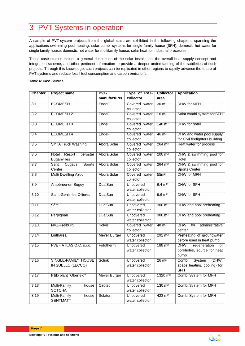
A sample of PVT-system projects from the global static are exhibited in the following chapters, spanning the
applications swimming pool heating, solar combi systems for single family house (SFH), domestic hot water for
single family house, domestic hot water for multifamily house, solar heat for industrial processes.
These case studies include a general description of the solar installation, the overall heat supply concept and
integration scheme, and other pertinent information to provide a deeper understanding of the subtleties of such
projects. Through this knowledge, such projects can be replicated in other regions to rapidly advance the future of
PVT systems and reduce fossil fuel consumption and carbon emissions.
Table 4: Case Studies
Chapter Project name PVT-
manufacturer
Type of PVT-
collector
Collector
area
Application
3.1 ECOMESH 1 EndeF Covered water
collector
30 m² DHW for MFH
3.2 ECOMESH 2 EndeF Covered water
collector
10 m² Solar combi system for SFH
3.3 ECOMESH 3 EndeF Covered water
collector
148 m² DHW for hotel
3.4 ECOMESH 4 EndeF Covered water
collector
46 m² DHW and water pool supply
for Civil firefighters building
3.5 SYTA Truck Washing Abora Solar Covered water
collector
264 m² Heat water for process
3.6 Hotel Resort Iberostar
Buganvilles
Abora Solar Covered water
collector
200 m² DHW & swimming pool for
Hotel
3.7 Sant Cugat’s Sports
Center
Abora Solar Covered water
collector
264 m² DHW & swimming pool for
Sports Center
3.8 Multi Dwelling Azud Abora Solar Covered water
collector
55m² DHW for MFH
3.9 Ambérieu-en-Bugey DualSun Uncovered
water collector
6.4 m² DHW for SFH
3.10 Saint-Genis-les-Ollières DualSun Uncovered
water collector
9.6 m² DHW for SFH
3.11 Sète DualSun Uncovered
water collector
300 m² DHW and pool preheating
3.12 Perpignan DualSun Uncovered
water collector
300 m² DHW and pool preheating
3.13 NVZ-Freiburg Solvis Covered water
collector
48 m² DHW for administrative
center
3.14 Lintharea Meyer Burger Uncovered
water collector
292 m² Preheating of groundwater
before used in heat pump
3.15 FVE - ATLAS O.C. s.r.o. Fototherm Uncovered
water collector
188 m² DHW, regeneration of
boreholes, source for heat
pump
3.16 SINGLE-FAMILY HOUSE
IN SUELLO (LECCO)
Solink Uncovered
water collector
26 m² Combi System (DHW,
space heating, cooling) for
SFH
3.17 P&D plant "Oberfeld" Meyer Burger Uncovered
water collector
1320 m² Combi System for MFH
3.18 Multi-Family house
SOTCHA
Caotec Uncovered
water collector
130 m² Combi System for MFH
3.19 Multi-Family house
SENTMATT
Solator Uncovered
water collector
423 m² Combi System for MFH

Page 8
3.20 SINGLE-FAMILY HOUSE
IN WETTSWIL AM ALBIS
Meyer Burger Uncovered
water collector
46 m² Borehole regeneration and
pool heating
3.21 FOOTBALL CLUB
HOUSE IN STENLOESE
RACELL Uncovered
water collector
165m² Combi System in a sports
club
3.22 Consolar SOLINK heating
system
Solink Uncovered
water collector
40 m² Solar combi system for SFH
3.23 GSE AIR'SYSTEM GSE Air collector 24 m² Space heating system for
SFH
3.24 Domestic Pilot and
Demonstration (P&D)
Sunovate Air collector 8 m ² Combi System for SFH
3.25 Active Office Naked Energy Vacuum tube
collector
27 m² Combi System for office
building
3.26 Henri Willig cheese factory Solarus Concentrator 226 m² Cheese production process
3.27 SOcool Office SunOyster Concentrator 34.2 m² Heating and cooling a office
building
3.28 Pilot PVT plant - University
of Catania
Dualsun Uncovered
water collector
3.3 m² DHW for SFH (simulated)
3.29 Pilot PVT plant- University
of Denmark
Racell
Technologies
Uncovered
water collector
3.1 m² DHW preparation and
source for heat pump
3.30 Pilot PVT plant – UCEEB
CTU
UCEEB CTU Covered water
collector
3,12 m2 DHW preparation
3.1 ECOMESH
3.1.1 Introduction and description
EndeF completed the installation and set into service of a hybrid solar system that supplies sanitary hot water
individually for multi-family house and electricity for the common consumptions of the building including a charging
system for electric vehicles. The project was within the framework of EU projects (LIFE) “NEW HOUSING
SOLUTIONS 4OLD (LIFE10 ENV / ES / 439),” Innovative Technologies for an Efficient Use of Energy Resources
and Housing Rehabilitation, promoted by the municipal association Zaragoza Vivienda.
Figure 7: View of the roof-mounting PVT installation in the urban centre of Zaragoza.
3.1.2 Solar installations

Existing PVT systems and solutions
Page 9
A total of 18 covered PVT collectors were installed in the roof of the building. The PVT model installed was the
ECOMESH model, developed and manufactured by EndeF, covering a total solar surface of 29.7 m2 and 4.14 kWp
electrical output. Solar field was oriented to south (0º) and an inclination of 25º, corresponding to the roof tilt.
3.1.3 Heat supply concept and integration of PVT collectors
The heat supply system is graphically explained in Figure 8. Solar field is proposed to cover the energy needs
derived from DHW dwellings and electricity for general uses, including a charging system for electric vehicles
located on the same building.
PVT panels were connected in parallel to provide hot water to the storage tank located in the lower plant of the
building. Since the DHW supply in Spain is set in 60ºC, an external device is located to guarantee the water
temperature, consisting of a gas boiler located on the same room. Electrical circuit were installed following the
requirements depicted in the local normative (RD 900/2015 or current at that time) and under self-consumption
regime, which means that it counted with the grid as a back-up system for the moments of no PVT electrical
production.
Figure 8: Visualisation of the PVT field for multi-family DHW.
3.1.4 Fact sheet
General Information
Project name [-] ECOMESH
Country [-] Spain
City [-] Zaragoza
Year of operation start [mm/yyyy] 05/2015
Page 10
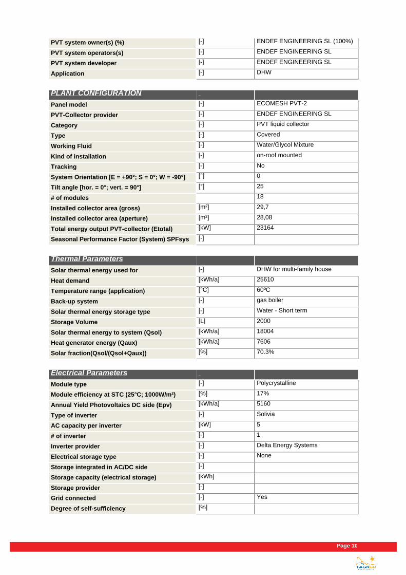
PVT system owner(s) (%) [-] ENDEF ENGINEERING SL (100%)
PVT system operators(s) [-] ENDEF ENGINEERING SL
PVT system developer [-] ENDEF ENGINEERING SL
Application [-] DHW
PLANT CONFIGURATION
Panel model [-] ECOMESH PVT-2
PVT-Collector provider [-] ENDEF ENGINEERING SL
Category [-] PVT liquid collector
Type [-] Covered
Working Fluid [-] Water/Glycol Mixture
Kind of installation [-] on-roof mounted
Tracking [-] No
System Orientation [E = +90°; S = 0°; W = -90°] [°] 0
Tilt angle [hor. = 0°; vert. = 90°] [°] 25
# of modules 18
Installed collector area (gross) [m²] 29,7
Installed collector area (aperture) [m²] 28,08
Total energy output PVT-collector (Etotal) [kW] 23164
Seasonal Performance Factor (System) SPFsys [-]
Thermal Parameters
Solar thermal energy used for [-] DHW for multi-family house
Heat demand [kWh/a] 25610
Temperature range (application) [°C] 60ºC
Back-up system [-] gas boiler
Solar thermal energy storage type [-] Water - Short term
Storage Volume [L] 2000
Solar thermal energy to system (Qsol) [kWh/a] 18004
Heat generator energy (Qaux) [kWh/a] 7606
Solar fraction(Qsol/(Qsol+Qaux)) [%] 70.3%
Electrical Parameters
Module type [-] Polycrystalline
Module efficiency at STC (25°C; 1000W/m²) [%] 17%
Annual Yield Photovoltaics DC side (Epv) [kWh/a] 5160
Type of inverter [-] Solivia
AC capacity per inverter [kW] 5
# of inverter [-] 1
Inverter provider [-] Delta Energy Systems
Electrical storage type [-] None
Storage integrated in AC/DC side [-]
Storage capacity (electrical storage) [kWh]
Storage provider [-]
Grid connected [-] Yes
Degree of self-sufficiency [%]

Existing PVT systems and solutions
Page 11
Self-Consumption fraction [%]
Economic Parameters
Total investment cost (excl. VAT) [€] 32985
PVT-collector loop (excl. VAT) [€] 16583
Solar thermal energy storage (excl. VAT) [€] 5038
Inverter (excl. VAT) [€] 1860
Electrical storage (excl. VAT) [€]
others (excl. VAT) [€]
Specific investment cost [€/m²]
Calculated solar thermal system life time [a] 20
Subsidy, € or % of total investment costs [€/%]
Fuel replaced [-] Gas
Cost for fuel replaced [€/MWhfuel] 30.11
Local feed-in tariff [€/MWhelectricity] 117.8
Sources
Author [-] ENDEF ENGINEERING SL
Company of Author [-] ENDEF ENGINEERING SL
E-mail [-] [email protected]
Phone [-] 34976365811
Homepage [-] http://endef.com/

Page 12
3.2 ECOMESH 2
3.2.1 Introduction and description
EndeF designed and carried out the installation of a 6 ECOMESH hybrid solar panels on the roof of a single-family
house located in Zaragoza (Spain) to provide DHW and electricity for family energy needs. The solar installation
also complements a biomass boiler to supply hot water for the underfloor heating, activated only during winter
months.
Figure 9: View of the 6-PVT solar installation in single family house.
3.2.2 Solar installations
Solar installation was composed by 6 ECOMESH PVT panels, with a total solar surface of 10 m2 and 1.38 kWp of
electrical output. PVT collectors were installed on the roof, with a tilt of 65º and faced to south (0º). Installation was
completed with thermal storage tank with a volume of 2000 l and 3 micro-inverters of 0.5 kW.
3.2.3 Heat supply concept and integration of PVT collectors
The heat supply system is graphically explained in Figure 10. Solar field is proposed to cover the energy needs
derived from DHW dwellings and electricity for general uses, as well as to give support to the biomass boiler for the
space heating, consisting on radiant floor.
PVT panels were connected in parallel to provide hot water to the storage tank located in the lower plant of the
building. Since the DHW supply in Spain is set in 60ºC, an external device is located to guarantee the water
temperature, consisting of a gas boiler located on the same room. Electrical circuit were installed following the
requirements depicted in the local normative (RD 900/2015 or current at that time) and under self-consumption
regime, which means that it counted with the grid as a back-up system for the moments of no PVT electrical
production.

Existing PVT systems and solutions
Page 13
Figure 10: Schematic visualisation of the PVT field in single family house.
3.2.4 Fact sheet
General Information
Project name [-] ECOMESH
Country [-] Spain
City [-] Zaragoza
Year of operation start [mm/yyyy] 08/2014
PVT system owner(s) (%) [-] ENDEF ENGINEERING SL (100%)
PVT system operators(s) [-] ENDEF ENGINEERING SL
PVT system developer [-] ENDEF ENGINEERING SL
Application [-] DHW + radiant floor
PLANT CONFIGURATION
Panel model [-] ECOMESH PVT-2
PVT-Collector provider [-] ENDEF ENGINEERING SL
Category [-] PVT liquid collector
Type [-] Covered
Working Fluid [-] Water/Glycol Mixture
Kind of installation [-] on-roof mounted
Tracking [-] No
System Orientation [E = +90°; S = 0°; W = -90°] [°] 0
Tilt angle [hor. = 0°; vert. = 90°] [°] 65

Page 14
# of modules 6
Installed collector area (gross) [m²] 10
Installed collector area (aperture) [m²] 9.36
Total energy output PVT-collector (Etotal) [kW] 8812
Seasonal Performance Factor (System) SPFsys [-]
Thermal Parameters
Solar thermal energy used for [-]
DHW + radiant floor for single-family house
Heat demand [kWh/a]
Temperature range (application) [°C] 45 - 60
Back-up system [-] Unknown
Solar thermal energy storage type [-] Water - Short term
Storage Volume [L] 1500
Solar thermal energy to system (Qsol) [kWh/a] 7165.5
Heat generator energy (Qaux) [kWh/a]
Solar fraction(Qsol/(Qsol+Qaux)) [%]
Electrical Parameters
Module type [-] Polycrystalline
Module efficiency at STC (25°C; 1000W/m²) [%] 17%
Annual Yield Photovoltaics DC side (Epv) [kWh/a] 1647.3
Type of inverter [-]
AC capacity per inverter [kW] 0.5
# of inverter [-] 3
Inverter provider [-]
Electrical storage type [-] None
Storage integrated in AC/DC side [-]
Storage capacity (electrical storage) [kWh]
Storage provider [-]
Grid connected [-] Yes
Degree of self-sufficiency [%]
Self-Consumption fraction [%]
Economic Parameters
Total investment cost (excl. VAT) [€]
PVT-collector loop (excl. VAT) [€]
Solar thermal energy storage (excl. VAT) [€]
Inverter (excl. VAT) [€]
Electrical storage (excl. VAT) [€]
others (excl. VAT) [€]
Specific investment cost [€/m²]
Calculated solar thermal system life time [a] 20
Subsidy, € or % of total investment costs [€/%]
Fuel replaced [-] gas
Cost for fuel replaced [€/MWhfuel] 30.11

Existing PVT systems and solutions
Page 15
Local feed-in tariff [€/MWhelectricity] 117.8
Sources
Author [-] ENDEF ENGINEERING SL
Company of Author [-] ENDEF ENGINEERING SL
E-mail [-] [email protected]
Phone [-] 34976365811
Homepage [-] http://endef.com/

Page 16
3.3 ECOMESH 3
3.3.1 Introduction and description
Installation of 90 ECOMESH hybrid solar panels able to generate electricity and heat simultaneously. Those panels
we installed for the preheating of domestic hot water (DHW) and for self-consumption of electricity without injection
to the public electricity grid. Its location is a luxury resort in Ibiza (Balearic Islands, Spain).
Figure 11: View of the PVT solar installation on the roof of a luxury hotel in Ibiza.
3.3.2 Solar installations
Solar installation was composed by 90 ECOMESH PVT panels, with a total solar surface of 147.6 m2 and 21.6 kWp
of electrical output. PVT collectors were installed on the roof, with a tilt of 20º and faced to south (0º) and a storage
volume of 9.000 l. The inverter device had a capacity of 20 kW.
3.3.3 Heat supply concept and integration of PVT collectors
The heat supply system is graphically explained in Figure 12. Solar field is proposed to cover the energy needs
derived from DHW dwellings and electricity for general uses in a luxury hotel.
PVT panels were connected in parallel to provide hot water to the storage tank. Since the DHW supply in Spain is
set in 60ºC, an external device is located to guarantee the water temperature, consisting of a gas boiler. Electrical
circuit were installed following the requirements depicted in the local normative (RD 900/2015 or current at that
time) and under self-consumption regime, which means that it counted with the grid as a back-up system for the
moments of no PVT electrical production.

Existing PVT systems and solutions
Page 17
Figure 12: Schematic visualisation of the PVT field in hotel.
3.3.4 Fact sheet
General Information
Project name [-] ECOMESH
Country [-] Spain
City [-] Ibiza
Year of operation start [mm/yyyy] 02/2017
PVT system owner(s) (%) [-]
ENDEF ENGINEERING SL (100%)
PVT system operators(s) [-] ENDEF ENGINEERING SL
PVT system developer [-] ENDEF ENGINEERING SL
Application [-] DHW
PLANT CONFIGURATION
Panel model [-] ECOMESH PVT-2
PVT-Collector provider [-] ENDEF ENGINEERING SL
Category [-] PVT liquid collector
Type [-] covered
Working Fluid [-] Water/Glycol Mixture
Kind of installation [-] on-roof mounted
Tracking [-] No
System Orientation [E = +90°; S = 0°; W = -90°] [°] 0

Page 18
Tilt angle [hor. = 0°; vert. = 90°] [°] 20
# of modules 90
Installed collector area (gross) [m²] 147.6
Installed collector area (aperture) [m²] 140.4
Total energy output PVT-collector (Etotal) [kW] 197100
Seasonal Performance Factor (System) SPFsys [-]
Thermal Parameters
Solar thermal energy used for [-] DHW for Hotel
Heat demand [kWh/a] 691489
Temperature range (application) [°C] 60
Back-up system [-] gas boiler
Solar thermal energy storage type [-] Water - Short term
Storage Volume [L] 9000
Solar thermal energy to system (Qsol) [kWh/a] 162500
Heat generator energy (Qaux) [kWh/a] 528989
Solar fraction(Qsol/(Qsol+Qaux)) [%] 23.50%
Electrical Parameters
Module type [-] Polycrystalline
Module efficiency at STC (25°C; 1000W/m²) [%] 17%
Annual Yield Photovoltaics DC side (Epv) [kWh/a] 34600
Type of inverter [-]
AC capacity per inverter [kW] 20
# of inverter [-] 1
Inverter provider [-]
Electrical storage type [-] None
Storage integrated in AC/DC side [-]
Storage capacity (electrical storage) [kWh]
Storage provider [-]
Grid connected [-] Yes
Degree of self-sufficiency [%]
Self-Consumption fraction [%]
Economic Parameters
Total investment cost (excl. VAT) [€]
PVT-collector loop (excl. VAT) [€] 49500 (only collectors)
Solar thermal energy storage (excl. VAT) [€]
Inverter (excl. VAT) [€]
Electrical storage (excl. VAT) [€]
others (excl. VAT) [€]
Specific investment cost [€/m²]
Calculated solar thermal system life time [a] 20
Subsidy, € or % of total investment costs [€/%]
Fuel replaced [-] fuel
Cost for fuel replaced [€/MWhfuel] 36,05

Existing PVT systems and solutions
Page 19
Local feed-in tariff [€/MWhelectricity] 117.8
Sources
Author [-] ENDEF ENGINEERING SL
Company of Author [-] ENDEF ENGINEERING SL
E-mail [-] [email protected]
Phone [-] 34976365811
Homepage [-] http://endef.com/

Page 20
3.4 ECOMESH 4
3.4.1 Introduction and description
This solar hybrid installation took place on the roof of the fire station No.1 of Zaragoza (Spain) to face the high
sanitary hot water consumption required by this building, resulting from the DHW needs and several swimming
pools. With this installation, Zaragoza has become the first Spanish city where this hybrid technology has been
installed on a public building.
Figure 13: View of the PVT field in firefighters building.
3.4.2 Solar installations
Solar installation was composed by 28 ECOMESH PVT panels, with a total solar surface of 46.2 m² and 6.72 kWp
of electrical output. PVT collectors were installed on the roof, with a tilt of 45º and faced to south (0º). Installation
was competed with thermal storage volume 3.000 l, distributed in two tanks, and a Fronius SYMO inverter of 8.2
kW of capacity.
3.4.3 Heat supply concept and integration of PVT collectors
The heat supply system is graphically explained in Figure 14. Solar field is proposed to cover the energy needs
derived from DHW dwellings and electricity for general uses in a firefighters building, whose main heat consumption
comes from the use of a swimming pool with high daily hot water consumption.
PVT panels were connected in parallel to provide hot water to the storage tank, where hot water was extracted at
different levels to obtain different temperatures. Hot water at maximum temperature was extracted for DHW
purposes, with extra supply coming from the gas boiler when needed to reach the required 60ºC. Hot water used
for swimming pool was extracted at medium level of the tank, to be provided at 30ºC.
Electrical circuit were installed following the requirements depicted in the local normative (RD 900/2015 or current
at that time) and under self-consumption regime, with grid connexion as a back-up system for the moments of no
PVT electrical production. An additional PV solar field is planned to be installed next to the existing PVT field, to
increase the electricity capacity of the solar roof installation, but its fulfilment is still under project stage.

Existing PVT systems and solutions
Page 21
Figure 14: Schematic visualisation of the PVT field in firefighters building.
3.4.4 Fact sheet
General Information
Project name [-] ECOMESH
Country [-] Spain
City [-] Zaragoza
Year of operation start [mm/yyyy] 01/2018
PVT system owner(s) (%) [-]
ENDEF ENGINEERING SL (100%)
PVT system operators(s) [-] ENDEF ENGINEERING SL
PVT system developer [-] ENDEF ENGINEERING SL
Application [-] DHW + pool suply
PLANT CONFIGURATION
Panel model [-] ECOMESH PVT-2
PVT-Collector provider [-] ENDEF ENGINEERING SL
Category [-] PVT liquid collector
Type [-] covered
Working Fluid [-] Water/Glycol Mixture
Kind of installation [-] on-roof mounted
Tracking [-] No
Page 22
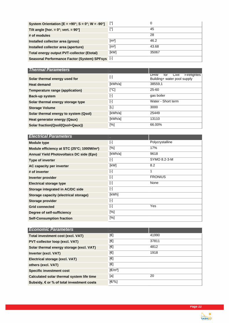
System Orientation [E = +90°; S = 0°; W = -90°] [°] 0
Tilt angle [hor. = 0°; vert. = 90°] [°] 45
# of modules 28
Installed collector area (gross) [m²] 46.2
Installed collector area (aperture) [m²] 43.68
Total energy output PVT-collector (Etotal) [kW] 35067
Seasonal Performance Factor (System) SPFsys [-]
Thermal Parameters
Solar thermal energy used for [-]
DHW for Civil Firefightes Building+ water pool supply
Heat demand [kWh/a] 38559,1
Temperature range (application) [°C] 25-60
Back-up system [-] gas boiler
Solar thermal energy storage type [-] Water - Short term
Storage Volume [L] 3000
Solar thermal energy to system (Qsol) [kWh/a] 25449
Heat generator energy (Qaux) [kWh/a] 13110
Solar fraction(Qsol/(Qsol+Qaux)) [%] 66.00%
Electrical Parameters
Module type [-] Polycrystalline
Module efficiency at STC (25°C; 1000W/m²) [%] 17%
Annual Yield Photovoltaics DC side (Epv) [kWh/a] 9618
Type of inverter [-] SYMO 8.2-3-M
AC capacity per inverter [kW] 8.2
# of inverter [-] 1
Inverter provider [-] FRONIUS
Electrical storage type [-] None
Storage integrated in AC/DC side [-]
Storage capacity (electrical storage) [kWh]
Storage provider [-]
Grid connected [-] Yes
Degree of self-sufficiency [%]
Self-Consumption fraction [%]
Economic Parameters
Total investment cost (excl. VAT) [€] 41990
PVT-collector loop (excl. VAT) [€] 37811
Solar thermal energy storage (excl. VAT) [€] 4812
Inverter (excl. VAT) [€] 1918
Electrical storage (excl. VAT) [€]
others (excl. VAT) [€]
Specific investment cost [€/m²]
Calculated solar thermal system life time [a] 20
Subsidy, € or % of total investment costs [€/%]

Existing PVT systems and solutions
Page 23
Fuel replaced [-] gas
Cost for fuel replaced [€/MWhfuel] 30.11
Local feed-in tariff [€/MWhelectricity] 117.8
Sources
Author [-] ENDEF ENGINEERING SL
Company of Author [-] ENDEF ENGINEERING SL
E-mail [-] [email protected]
Phone [-] 34976365811
Homepage [-] http://endef.com/

Page 24
3.5 SYTA Truck Washing
3.5.1 Introduction and description
The installation is done in an existing truck tank laundry. The consumption of hot water in this industry is huge,
depending on the exact process they use water between 40 and 60ºC.
The existing facility consists of biomass and diesel boilers that heat water that is stored in tanks.
The motivation of the owner to perform a PVT installation was profitability, and therefore the economic savings in
his business.
Figure 15: SYTA installation
3.5.2 Solar installations
At the beginning of 2019, 160 panels (aH60 from Abora Solar) were installed on an industrial vaulted roof. (total
collector area, 264 m2; 41,6 kWp electrical output). The modules are oriented to the south (0 °) with an inclination
angle of 35 °.
3.5.3 Heat supply concept and integration of PVT collectors
The heat supply system is depicted in simplified form in Figure below. The existent system consisted of two
boilers: biomass and oil. The boilers heat the tank storage, the heated water is used to wash the tanker trucks.
The building is like a garage without space heating. Annex to the garage there is a small office with its own
heating system.
For the integration of the solar system was installed a primary water tank of 6000 litres which is heated with the
160 collectors. The outlet of the tank is connected to the inlet of the existing tank storage. When the temperature
of that existing tank is lower than setpoint the boiler heats it.

Existing PVT systems and solutions
Page 25
Figure 16: Visualisation of the PVT system “SYTA”.
3.5.4 Fact sheet
General Information Project name [-] SYTA Truck Washing
Country [-] Spain
City [-] Alfajarin (ZGZ)
Year of operation start [mm/yyyy] 03/2019
PVT system owner(s) (%) [-] Company SYTA
PVT system operators(s) [-] Company SYTA
PVT system developer [-] Ingeniería Torne
Application [-]
Heat water for process & selfconsumption electricity
PLANT CONFIGURATION Panel model [-] aH60
PVT-Collector provider [-] Abora Solar
Category [-] PVT liquid collector
Type [-] covered
Working Fluid [-] Water/Glycol Mixture

Page 26
Kind of installation [-] on-roof mounted
Tracking [-] No
System Orientation [E = +90°; S = 0°; W = -90°]
[°] 0
Tilt angle [hor. = 0°; vert. = 90°] [°] 40
# of modules [-] 160
Installed collector area (gross) [m²] 264
Installed collector area (aperture) [m²] 252,6
Total energy output PVT-collector (Etotal) [kWh] 291.978
Seasonal Performance Factor (System) SPFsys
[-]
Thermal Parameters
Solar thermal energy used for [-] Heat water for process
Heat demand [kWh/a] 664.462
Temperature range (application) [°C] 40-60
Back-up system [-] oil boiler
Solar thermal energy storage type [-] Water - Short term
Storage Volume [L] 6.000
Solar thermal energy to system (Qsol) [kWh/a] 235.166
Heat generator energy (Qaux) [kWh/a] 429.296
Solar fraction(Qsol/(Qsol+Qaux)) [%] 35
Electrical Parameters
Module type [-] Monocrystalline
Module efficiency at STC (25°C; 1000W/m²) [%] 17
Annual Yield Photovoltaics DC side (Epv) [kWh/a] 55.934
Type of inverter [-] MPPT-Self consumption
AC capacity per inverter [kW] 21
# of inverter [-] 2
Inverter provider [-] Growatt
Electrical storage type [-] None
Storage integrated in AC/DC side [-]
Storage capacity (electrial storage) [kWh]
Storage provider [-]
Grid connected [-] Yes
Degree of self-sufficiency [%] 30
Self-Consumption fraction [%] 100

Existing PVT systems and solutions
Page 27
Economic Parameters Total investment cost (excl. VAT) [€] 164.170
PVT-collektor loop (excl. VAT) [€] 119.776
Solar thermal energy storage (excl. VAT) [€] 7.980
Inverter (excl. VAT) [€] 5.746
Electrical storage (excl. VAT) [€]
others (excl. VAT) [€] 30.668
Specific investment cost [€/m²] 621
Calculated solar thermal system life time [a] 20
Subsidy, € or % of total investment costs [€/%]
Fuel replaced [-] oil
Cost for fuel replaced [€/MWhfuel] 85
Local feed-in tariff [€/MWhelectricity] 90
Sources Author [-] Marta Cañada
Company of Author [-] Abora Solar
E-mail [-] [email protected]
Phone [-] +34 876 247 096
Homepage [-] www.abora-solar.com

Page 28
3.6 Hotel Resort Iberostar Buganvilles
3.6.1 Introduction and description
The installation is done in an existing 4 stars Hotel in Tenerife (Canary Islands). The motivation to deploy it was
the rentability for the business, because of the huge non-seasonal consumption of domestic heat water. The hotel
has 1006 seats. The heat existing system to produce DHW is propane gas boilers.
August 2019, 102 panels (aH72 from Abora Solar) were installed on the flat roofs at different levels. (total
collector area, 200 m2; 30,6 kWp electrical output). The modules are oriented to the south (0 °) with an inclination
angle of 45 °.
3.6.2 Heat supply concept and integration of PVT collectors
The heat supply system is depicted in simplified form in Figure 4. The existent system consisted of a propane gas
boiler. The boiler kept DHW tanks warm.
For the integration of the solar system were installed a primary water tanks with a total volume of 10000 litres
which are heated with the 102 collectors. The outlet of the tank is connected to the inlet of the existing tank
storage. When the temperature of that existing tanks is lower than set point the boiler heats them.
Figure 17:View of PVT in the flat roofs of Hotel Iberostar Buganvilles

Existing PVT systems and solutions
Page 29
Figure 18: Visualisation of the PVT system “Hotel Iberostar Buganvilles”.
3.6.3 Fact sheet
General Information Project name [-] Iberostar Hotel Buganvilles
Country [-] Spain
City [-] Tenerife
Year of operation start [mm/yyyy] 08/2019
PVT system owner(s) (%) [-] Iberostar Hotels
PVT system operators(s) [-] Iberostar Buganvilles
PVT system developer [-] Ingeniería Insiteca
Application [-]
DHW & selfconsumption electricity
PLANT CONFIGURATION Panel model [-] aH72
PVT-Collector provider [-] Abora solar
Category [-] PVT liquid collector
Type [-] covered
Working Fluid [-] Water

Page 30
Kind of installation [-] on-roof mounted
Tracking [-] No
System Orientation [E = +90°; S = 0°; W = -90°]
[°] 0
Tilt angle [hor. = 0°; vert. = 90°] [°] 45
# of modules [-] 102
Installed collector area (gross) [m²] 199,92
Installed collector area (aperture) [m²] 191,76
Total energy output PVT-collector (Etotal) [kWh] 230.729
Seasonal Performance Factor (System) SPFsys
[-]
Thermal Parameters
Solar thermal energy used for [-] DHW
Heat demand [kWh/a] 881.901
Temperature range (application) [°C] 40-70
Back-up system [-] gas boiler
Solar thermal energy storage type [-] Water - Short term
Storage Volume [L] 10.000
Solar thermal energy to system (Qsol) [kWh/a] 190.259
Heat generator energy (Qaux) [kWh/a] 691.642
Solar fraction(Qsol/(Qsol+Qaux)) [%] 22
Electrical Parameters
Module type [-] Monocrystalline
Module efficiency at STC (25°C; 1000W/m²)
[%] 17
Annual Yield Photovoltaics DC side (Epv) [kWh/a] 40.470
Type of inverter [-] MPPT-Self consumption
AC capacity per inverter [kW] 15
# of inverter [-] 2
Inverter provider [-] Fronius
Electrical storage type [-] None
Storage integrated in AC/DC side [-]
Storage capacity (electrial storage) [kWh]
Storage provider [-]
Grid connected [-] Yes
Degree of self-sufficiency [%] 17
Self-Consumption fraction [%] 100

Existing PVT systems and solutions
Page 31
Economic Parameters Total investment cost (excl. VAT) [€] 132.383
PVT-collektor loop (excl. VAT) [€] 88.265
Solar thermal energy storage (excl. VAT) [€] 13.639
Inverter (excl. VAT) [€] 5.124
Electrical storage (excl. VAT) [€]
others (excl. VAT) [€] 25.355
Specific investment cost [€/m²] 662
Calculated solar thermal system life time [a] 20
Subsidy, € or % of total investment costs [€/%]
Fuel replaced [-] gas
Cost for fuel replaced [€/MWhfuel] 66
Local feed-in tariff [€/MWhelectricity] 104
Sources Author [-] Marta Cañada
Company of Author [-] Abora Solar
E-mail [-] [email protected]
Phone [-] +34 876 247 096
Homepage [-] www.abora-solar.com

Page 32
3.7 Sant Cugat’s Sports Center
3.7.1 Introduction and description
This installation is a pilot facility of the European Project "Chess-Setup": https://www.chess-setup.net/sant-cugat.
There are multiple heat circuits in the sports center for: each of the pools, the different shower areas and the
spaces heating. All powered with several natural gas boilers.
Figure 19: View of the PVT collectors “Sant Cugat’s Sports Center”.
3.7.2 Solar installations
The proposed system will perfectly match the energy needs of a sport centre, as it will be designed to provide
heat at peak times (week-end) thanks to its inertia.
The system will also supply the domestic hot water to an existing athletic tracks attached to the sport centre. In
this way, the implementation will constitute a retrofitting solution.
3.7.3 Heat supply concept and integration of PVT collectors
The heat supply system is represented in simplified form in Figure 7. The existing natural gas boiler systems have
been maintained. And for some of the heat circuits, thermal energy storage tank (TES) of 160 m3 volume, 160
PVT, a heat pump (Water-water) and a buffer tank were incorporated.
The circuit allows the energy stored in the TES to go directly to heating consumption circuits if the temperature is
very high, or in more usual way it works with the heat pump.
Figure 20: System Design (source Chess-Setup).

Existing PVT systems and solutions
Page 33
Figure 21: Visualisation of the PVT system “Sant Cugat’s Sports Center”.
3.7.4 Fact sheet
General Information Project name [-] Sant Cugat's Sport Center
Country [-] Spain
City [-] Sant Cugat (BCN)
Year of operation start [mm/yyyy] 05/2019
PVT system owner(s) (%) [-] Ajuntament Sant Cugat
PVT system operators(s) [-] Eurofitness
PVT system developer [-] BCN Ecología
Application [-]
Electricity for self-consumption & heating of swimming pools &
DHW (shower)
PLANT CONFIGURATION Panel model [-] aH60
PVT-Collector provider [-] Abora Solar
Category [-] PVT liquid collector
Type [-] covered
Working Fluid [-] Water/Glycol Mixture

Page 34
Kind of installation [-] on-roof mounted
Tracking [-] No
System Orientation [E = +90°; S = 0°; W = -90°]
[°] 25
Tilt angle [hor. = 0°; vert. = 90°] [°] 25
# of modules [-] 160
Installed collector area (gross) [m²] 264
Installed collector area (aperture) [m²] 252,6
Total energy output PVT-collector (Etotal) [kWh] 284.035
Seasonal Performance Factor (System) SPFsys
[-]
Thermal Parameters
Solar thermal energy used for [-] DHW & swimming pool
Heat demand [kWh/a] 1.117.115
Temperature range (application) [°C] 30-70
Back-up system [-] gas boiler
Solar thermal energy storage type [-] Water - Long term
Storage Volume [L] 160.000
Solar thermal energy to system (Qsol) [kWh/a] 230.363
Heat generator energy (Qaux) [kWh/a] 886.752
Solar fraction(Qsol/(Qsol+Qaux)) [%] 21
Electrical Parameters
Module type [-] Monocrystalline
Module efficiency at STC (25°C; 1000W/m²) [%] 17
Annual Yield Photovoltaics DC side (Epv) [kWh/a] 53.672
Type of inverter [-] MPPT-Self consumption
AC capacity per inverter [kW] 20
# of inverter [-] 2
Inverter provider [-] Ingeteam
Electrical storage type [-] None
Storage integrated in AC/DC side [-]
Storage capacity (electrial storage) [kWh]
Storage provider [-]
Grid connected [-] Yes
Degree of self-sufficiency [%] 26
Self-Consumption fraction [%] 100

Existing PVT systems and solutions
Page 35
Economic Parameters Total investment cost (excl. VAT) [€] 232.078
PVT-collektor loop (excl. VAT) [€] 126.234
Solar thermal energy storage (excl. VAT) [€] 60.210
Inverter (excl. VAT) [€] 6.824
Electrical storage (excl. VAT) [€]
others (excl. VAT) [€] 38.810
Specific investment cost [€/m²] 879
Calculated solar thermal system life time [a] 20
Subsidy, € or % of total investment costs [€/%]
Fuel replaced [-] gas
Cost for fuel replaced [€/MWhfuel] 60
Local feed-in tariff [€/MWhelectricity] 89
Sources Author [-] Marta Cañada
Company of Author [-] Abora Solar
E-mail [-] [email protected]
Phone [-] +34 876 247 096
Homepage [-] www.abora-solar.com

Page 36
3.8 Multi Dwelling Azud
3.8.1 Introduction and description
This installation was mounted in a new multi dwelling building of new construction. In Spain is mandatory include for new buildings renewables energy to reduce CO2 at least of the DHW demand.
The building consists of 42 apartments with a forecast of 210 people and an outdoor pool.
Figure 22: View of the PVT panels “Multi dwelling Azud”.
3.8.2 Solar installations
This installation was completed in February 2019. 28 aH72 panels of Abora Solar were mounted on its flat roof.
The machine room is also on the roof. The total area of collectors is 55 m2 with 8.4 kWp electrical output. The
modules are oriented to the south-west (-20 °) with an inclination angle of 45 °.
3.8.3 Heat supply concept and integration of PVT collectors
The heat supply system is depicted in simplified form in Figure 9. The auxiliary system consisted of a natural gas
boiler. The PVT's collectors heat the primary tank with a volume of 3000 litres.
The outlet of the primary tank is connected to the inlet of the auxiliary tank storage. When the temperature of that
auxiliary tank is lower than set point the boiler heats them.

Existing PVT systems and solutions
Page 37
Figure 23: Visualisation of the PVT system “Multi dwelling Azud”.
3.8.4 Fact sheet
General Information Project name [-] Multi Dwelling Azud
Country [-] Spain
City [-] Zaragoza
Year of operation start [mm/yyyy] 02/2019
PVT system owner(s) (%) [-] Private owners
PVT system operators(s) [-] Private owners
PVT system developer [-] Oscar Del Castillo
Application [-]
DHW & selfconsumption electricity
PLANT CONFIGURATION Panel model [-] aH72
PVT-Collector provider [-] Abora Solar
Category [-] PVT liquid collector
Type [-] covered
Working Fluid [-] Water/Glycol Mixture

Page 38
Kind of installation [-] on-roof mounted
Tracking [-] No
System Orientation [E = +90°; S = 0°; W = -90°]
[°] -20
Tilt angle [hor. = 0°; vert. = 90°] [°] 45
# of modules [-] 28
Installed collector area (gross) [m²] 54,88
Installed collector area (aperture) [m²] 52,64
Total energy output PVT-collector (Etotal) [kWh] 61.565
Seasonal Performance Factor (System) SPFsys
[-]
Thermal Parameters
Solar thermal energy used for [-] DHW
Heat demand [kWh/a] 99.133
Temperature range (application) [°C] 40-60
Back-up system [-] gas boiler
Solar thermal energy storage type [-] Water - Short term
Storage Volume [L] 3.000
Solar thermal energy to system (Qsol) [kWh/a] 49.137
Heat generator energy (Qaux) [kWh/a] 49.996
Solar fraction(Qsol/(Qsol+Qaux)) [%] 50
Electrical Parameters
Module type [-] Monocrystalline
Module efficiency at STC (25°C; 1000W/m²) [%] 17
Annual Yield Photovoltaics DC side (Epv) [kWh/a] 12.428
Type of inverter [-] MPPT-Self consumption
AC capacity per inverter [kW] 8,5
# of inverter [-] 1
Inverter provider [-] Kostal
Electrical storage type [-] None
Storage integrated in AC/DC side [-]
Storage capacity (electrial storage) [kWh]
Storage provider [-]
Grid connected [-] Yes
Degree of self-sufficiency [%] 60
Self-Consumption fraction [%] 100

Existing PVT systems and solutions
Page 39
Economic Parameters Total investment cost (excl. VAT) [€] 38.664
PVT-collektor loop (excl. VAT) [€] 21.456
Solar thermal energy storage (excl. VAT) [€] 3.990
Inverter (excl. VAT) [€] 2.015
Electrical storage (excl. VAT) [€]
others (excl. VAT) [€] 11.203
Specific investment cost [€/m²] 704
Calculated solar thermal system life time [a] 20
Subsidy, € or % of total investment costs [€/%]
Fuel replaced [-] gas
Cost for fuel replaced [€/MWhfuel] 69
Local feed-in tariff [€/MWhelectricity] 140
Sources Author [-] Marta Cañada
Company of Author [-] Abora Solar
E-mail [-] [email protected]
Phone [-] +34 876 247 096
Homepage [-] www.abora-solar.com

Page 40
3.9 Ambérieu-en-Bugey
3.9.1 Introduction and description
https://dualsun.com/fr/realisations/amberieu-fr-4pvt
The object concerned a PVT DHW preheating in a single-family. It was installed in 2013.
Figure 24: View of the PVT system on the roof of the single-family house in Ambérieu.
3.9.2 Solar installations
4 PVT collectors (DualSun 250Wp) were installed on the tilted roof of the building (total collector area, 6.4 m²; 1.0 kWp electrical output). The modules are oriented to the southwest (40°) with an inclination angle of 20°.
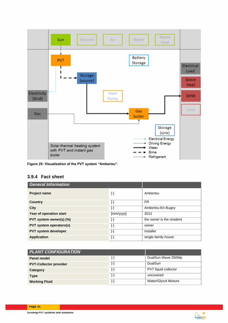
3.9.3 Heat supply concept and integration of PVT collectors
The heat supply system is depicted in simplified form in Figure 25. It is preheating a tank before an instant gas
boiler.
Existing PVT systems and solutions
Page 41
Figure 25: Visualisation of the PVT system “Amberieu”.
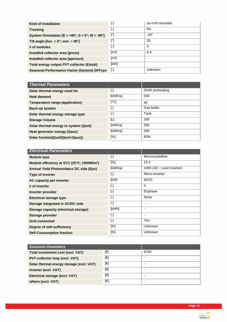
3.9.4 Fact sheet
General Information
Project name [-] Amberieu
Country [-] FR
City [-] Amberieu-En-Bugey
Year of operation start [mm/yyyy] 2012
PVT system owner(s) (%) [-] the owner is the resident
PVT system operators(s) [-] owner
PVT system developer [-] installer
Application [-] single-family house
PLANT CONFIGURATION
Panel model [-] DualSun Wave 250Wp
PVT-Collector provider [-] DualSun
Category [-] PVT liquid collector
Type [-] uncovered
Working Fluid [-] Water/Glycol Mixture
Page 42
Kind of installation [-] on-roof mounted
Tracking [-] No
System Orientation [E = +90°; S = 0°; W = -90°] [°] -40°
Tilt angle [hor. = 0°; vert. = 90°] [°] 20
# of modules [-] 4
Installed collector area (gross) [m²] 6.4
Installed collector area (aperture) [m²] -
Total energy output PVT-collector (Etotal) [kW]
Seasonal Performance Factor (System) SPFsys [-] unknown
Thermal Parameters
Solar thermal energy used for [-] DHW preheating
Heat demand [kWh/a] 500
Temperature range (application) [°C] 45
Back-up system [-] Gas boiler
Solar thermal energy storage type [-] Tank
Storage Volume [L] 200
Solar thermal energy to system (Qsol) [kWh/a] 300
Heat generator energy (Qaux) [kWh/a] 200
Solar fraction(Qsol/(Qsol+Qaux)) [%] 60%
Electrical Parameters
Module type [-] Monocrystalline
Module efficiency at STC (25°C; 1000W/m²) [%] 15.4
Annual Yield Photovoltaics DC side (Epv) [kWh/a] 1000 (AC = post inverter)
Type of inverter [-] Micro-inverter
AC capacity per inverter [kW] M215
# of inverter [-] 4
Inverter provider [-] Enphase
Electrical storage type [-] None
Storage integrated in AC/DC side [-] -
Storage capacity (electrical storage) [kWh] -
Storage provider [-] -
Grid connected [-] Yes
Degree of self-sufficiency [%] Unknown
Self-Consumption fraction [%] Unknown
Economic Parameters
Total investment cost (excl. VAT) [€] 6700
PVT-collector loop (excl. VAT) [€] -
Solar thermal energy storage (excl. VAT) [€] -
Inverter (excl. VAT) [€] -
Electrical storage (excl. VAT) [€] -
others (excl. VAT) [€] -

Existing PVT systems and solutions
Page 43
Specific investment cost [€/m²] 1050
Calculated solar thermal system life time [a] 25
Subsidy, € or % of total investment costs [€/%] 1000
Fuel replaced [-] Gas, Elec
Cost for fuel replaced [€/MWhfuel] 80, 160
Local feed-in tariff [€/MWhelectricity]
60 (only for surplus from self-consumption)
Sources
Author [-] Laetitia Brottier
Company of Author [-] DualSun
E-mail [-] [email protected]
Phone [-] "+33413415371"
Homepage [-] www.dualsun.fr

Page 44
3.10 Saint-Genis-les-Ollières
3.10.1 Introduction and description
https://dualsun.com/en/realisations/genis-fr-2013-6pvt-6pv-en/
The object concerned a PVT DHW preheating in a single-family. It was installed in 2012.
Figure 26: View of the PVT system on the roof of the single-family house in St Genis
3.10.2 Solar installations
6 PVT collectors (DualSun 250Wp) were installed on the tilted roof of the building (total collector area, 9.6 m2; 1.5 kWp electrical output). The modules are oriented to the south (5°) with an inclination angle of 30°.
3.10.3 Heat supply concept and integration of PVT collectors
The heat supply system is depicted in simplified form in Figure 27. It is preheating a tank before an instant gas
boiler.

Existing PVT systems and solutions
Page 45
Figure 27: Visualisation of the PVT system “St Genis”.
3.10.4 Fact sheet
General Information
Project name [-] St Genis
Country [-] FR
City [-] Saint-Genis-Les-Ollieres
Year of operation start [mm/yyyy] 2012
PVT system owner(s) (%) [-] the owner is the resident
PVT system operators(s) [-] owner
PVT system developer [-] installer
Application [-] single-family house
PLANT CONFIGURATION
Panel model [-] DualSun Wave 250Wp
PVT-Collector provider [-] DualSun
Category [-] PVT liquid collector
Type [-] uncovered
Working Fluid [-] Water/Glycol Mixture
Kind of installation [-] in-roof mounted
Tracking [-] No

Page 46
System Orientation [E = +90°; S = 0°; W = -90°] [°] 5°
Tilt angle [hor. = 0°; vert. = 90°] [°] 30
# of modules [-] 6
Installed collector area (gross) [m²] 9.6
Installed collector area (aperture) [m²] -
Total energy output PVT-collector (Etotal) [kW]
Seasonal Performance Factor (System) SPFsys [-] unknown
Thermal Parameters
Solar thermal energy used for [-] DHW preheating
Heat demand [kWh/a] 700
Temperature range (application) [°C] 45
Back-up system [-] Gas boiler
Solar thermal energy storage type [-] Tank
Storage Volume [L] 300
Solar thermal energy to system (Qsol) [kWh/a] 410
Heat generator energy (Qaux) [kWh/a] 290
Solar fraction(Qsol/(Qsol+Qaux)) [%] 59%
Electrical Parameters
Module type [-] Monocrystalline
Module efficiency at STC (25°C; 1000W/m²) [%] 15,4
Annual Yield Photovoltaics DC side (Epv) [kWh/a] 1150 (AC = post inverter)
Type of inverter [-] Micro-inverter
AC capacity per inverter [kW] M215
# of inverter [-] 6
Inverter provider [-] Enphase
Electrical storage type [-] None
Storage integrated in AC/DC side [-] -
Storage capacity (electrical storage) [kWh] -
Storage provider [-] -
Grid connected [-] Yes
Degree of self-sufficiency [%] Unknown
Self-Consumption fraction [%] Unknown
Economic Parameters
Total investment cost (excl. VAT) [€] 10000
PVT-collector loop (excl. VAT) [€] -
Solar thermal energy storage (excl. VAT) [€] -
Inverter (excl. VAT) [€] -
Electrical storage (excl. VAT) [€] -
others (excl. VAT) [€] -
Specific investment cost [€/m²] 1050
Calculated solar thermal system life time [a] 25

Existing PVT systems and solutions
Page 47
Subsidy, € or % of total investment costs [€/%] 1500
Fuel replaced [-] Gas, Elec
Cost for fuel replaced [€/MWhfuel] 80, 160
Local feed-in tariff [€/MWhelectricity]
60 (only for surplus from self-consumption)
Sources
Author [-] Laetitia Brottier
Company of Author [-] DualSun
E-mail [-] [email protected]
Phone [-] "+33413415371"
Homepage [-] www.dualsun.fr

Page 48
3.11 Sète
3.11.1 Introduction and description
https://dualsun.com/en/realisations/sete-fr-2016-180pvt-en/
The object concerned a PVT municipal indoor swimming pool installation for the preheating of the pools and the
showers. It was installed in 2016.
Figure 28: View of the PVT canopy for the municipal swimming pool in Sète
3.11.2 Solar installations
180 PVT collectors (DualSun 250Wp) were installed on the tilted roof of the building (total collector area, 300.0 m2; 45 kWp electrical output). The modules are oriented to the southeast (20°) with an inclination angle of 10°.
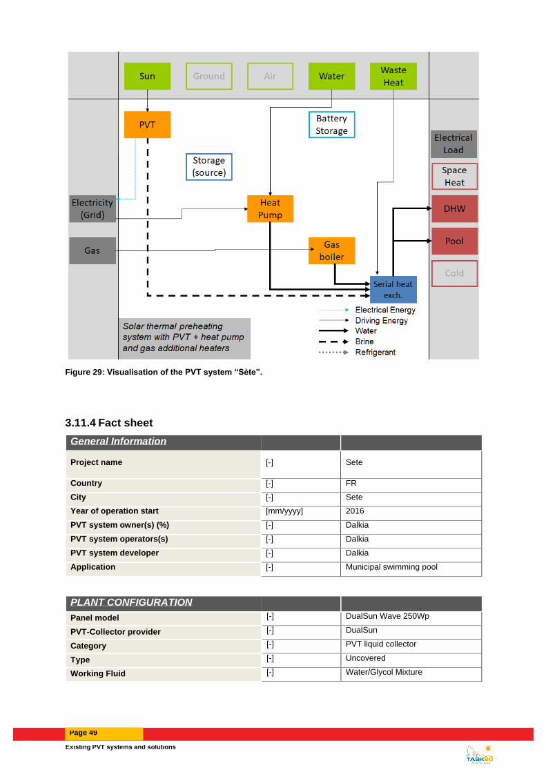
3.11.3 Heat supply concept and integration of PVT collectors
The heat supply system is depicted in simplified form in Figure 29. It is preheating a tank before an internal network
with a heat pump and a gas additional boilers trough serial heat exchangers.
Existing PVT systems and solutions
Page 49
Figure 29: Visualisation of the PVT system “Sète”.
3.11.4 Fact sheet
General Information
Project name [-] Sete
Country [-] FR
City [-] Sete
Year of operation start [mm/yyyy] 2016
PVT system owner(s) (%) [-] Dalkia
PVT system operators(s) [-] Dalkia
PVT system developer [-] Dalkia
Application [-] Municipal swimming pool
PLANT CONFIGURATION
Panel model [-] DualSun Wave 250Wp
PVT-Collector provider [-] DualSun
Category [-] PVT liquid collector
Type [-] Uncovered
Working Fluid [-] Water/Glycol Mixture

Page 50
Kind of installation [-] Canopy
Tracking [-] No
System Orientation [E = +90°; S = 0°; W = -90°] [°] 20°
Tilt angle [hor. = 0°; vert. = 90°] [°] 10
# of modules [-] 180
Installed collector area (gross) [m²] 300
Installed collector area (aperture) [m²] -
Total energy output PVT-collector (Etotal) [kW]
Seasonal Performance Factor (System) SPFsys [-] unknown
Thermal Parameters
Solar thermal energy used for [-] DHW and pool preheating
Heat demand [kWh/a] 1 180 835 Temperature range (application) [°C] 30
Back-up system [-] HeatPump and Gas boilers
Solar thermal energy storage type [-] -
Storage Volume [L] -
Solar thermal energy to system (Qsol) [kWh/a] 82100
Heat generator energy (Qaux) [kWh/a] 1 098 735
Solar fraction(Qsol/(Qsol+Qaux)) [%] 7%
Electrical Parameters
Module type [-] Monocrystalline
Module efficiency at STC (25°C; 1000W/m²) [%] 15.4
Annual Yield Photovoltaics DC side (Epv) [kWh/a] 59115 (AC = post inverter)
Type of inverter [-] Unknown
AC capacity per inverter [kW] Unknown
# of inverter [-] Unknown
Inverter provider [-] Unknown
Electrical storage type [-] None
Storage integrated in AC/DC side [-] -
Storage capacity (electrical storage) [kWh] -
Storage provider [-] -
Grid connected [-] Yes
Degree of self-sufficiency [%] Unknown
Self-Consumption fraction [%] Unknown
Economic Parameters
Total investment cost (excl. VAT) [€] 350 000
PVT-collector loop (excl. VAT) [€] -
Solar thermal energy storage (excl. VAT) [€] -
Inverter (excl. VAT) [€] -
Electrical storage (excl. VAT) [€] -
others (excl. VAT) [€] -

Existing PVT systems and solutions
Page 51
Specific investment cost [€/m²] 1170
Calculated solar thermal system life time [a] 25
Subsidy, € or % of total investment costs [€/%] 175 000
Fuel replaced [-] Gas, Elec
Cost for fuel replaced [€/MWhfuel] Unknown
Local feed-in tariff [€/MWhelectricity] 131
Sources
Author [-] Laetitia Brottier
Company of Author [-] DualSun
E-mail [-] [email protected]
Phone [-] "+33413415371"
Homepage [-] www.dualsun.fr

Page 52
3.12 Perpignan
3.12.1 Introduction and description
The object concerned a PVT municipal indoor swimming pool installation for the preheating of the pools and the
showers. It was installed in 2016.
Figure 30: View of the PVT canopy for the municipal swimming pool in Perpignan
3.12.2 Solar installations
180 PVT collectors (DualSun 250Wp) were installed on the tilted roof of the building (total collector area, 300.0 m2; 45 kWp electrical output). The modules are oriented to the south (0°) with an inclination angle of 10°.
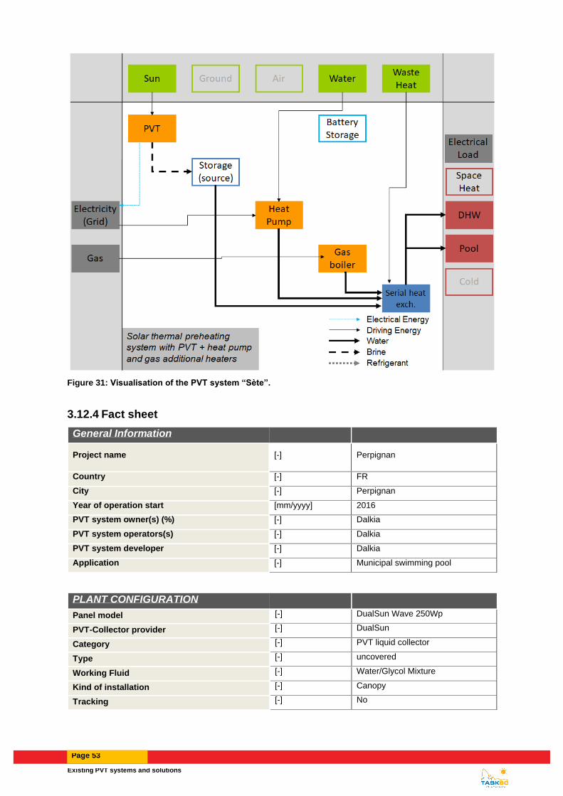
3.12.3 Heat supply concept and integration of PVT collectors
The heat supply system is depicted in simplified form in Figure 31. It is preheating a tank before an internal network
with a gas additional boiler trough serial heat exchangers.
Existing PVT systems and solutions
Page 53
Figure 31: Visualisation of the PVT system “Sète”.
3.12.4 Fact sheet
General Information
Project name [-] Perpignan
Country [-] FR
City [-] Perpignan
Year of operation start [mm/yyyy] 2016
PVT system owner(s) (%) [-] Dalkia
PVT system operators(s) [-] Dalkia
PVT system developer [-] Dalkia
Application [-] Municipal swimming pool
PLANT CONFIGURATION
Panel model [-] DualSun Wave 250Wp
PVT-Collector provider [-] DualSun
Category [-] PVT liquid collector
Type [-] uncovered
Working Fluid [-] Water/Glycol Mixture
Kind of installation [-] Canopy
Tracking [-] No

Page 54
System Orientation [E = +90°; S = 0°; W = -90°] [°] 0°
Tilt angle [hor. = 0°; vert. = 90°] [°] 10
# of modules [-] 180
Installed collector area (gross) [m²] 300
Installed collector area (aperture) [m²] -
Total energy output PVT-collector (Etotal) [kW]
Seasonal Performance Factor (System) SPFsys [-] unknown
Thermal Parameters
Solar thermal energy used for [-] DHW and pool preheating
Heat demand [kWh/a] 1 140 520 Temperature range (application) [°C] 30
Back-up system [-] Gas boiler
Solar thermal energy storage type [-] -
Storage Volume [L] -
Solar thermal energy to system (Qsol) [kWh/a] 119 870
Heat generator energy (Qaux) [kWh/a] 1 020 650
Solar fraction(Qsol/(Qsol+Qaux)) [%] 12%
Electrical Parameters
Module type [-] Monocrystalline
Module efficiency at STC (25°C; 1000W/m²) [%] 15.4
Annual Yield Photovoltaics DC side (Epv) [kWh/a] 63 940 (AC = post inverter)
Type of inverter [-] Unknown
AC capacity per inverter [kW] Unknown
# of inverter [-] Unknown
Inverter provider [-] Unknown
Electrical storage type [-] None
Storage integrated in AC/DC side [-] -
Storage capacity (electrical storage) [kWh] -
Storage provider [-] -
Grid connected [-] Yes
Degree of self-sufficiency [%] Unknown
Self-Consumption fraction [%] Unknown
Economic Parameters
Total investment cost (excl. VAT) [€] 350 000
PVT-collector loop (excl. VAT) [€] -
Solar thermal energy storage (excl. VAT) [€] -
Inverter (excl. VAT) [€] -
Electrical storage (excl. VAT) [€] -
others (excl. VAT) [€] -
Specific investment cost [€/m²] 1170
Calculated solar thermal system life time [a] 25

Existing PVT systems and solutions
Page 55
Subsidy, € or % of total investment costs [€/%] 175 000
Fuel replaced [-] Gas
Cost for fuel replaced [€/MWhfuel] Unknown
Local feed-in tariff [€/MWhelectricity] 131
Sources
Author [-] Laetitia Brottier
Company of Author [-] DualSun
E-mail [-] [email protected]
Phone [-] "+33413415371"
Homepage [-] www.dualsun.fr

Page 56
3.13 NVZ-Freiburg
3.13.1 Introduction and description
The new administrative center (Neues Verwaltungszentrum: NVZ) of the city of Freiburg (D) has been designed and built with the objective of a plus-energy balance. The NVZ has been commissioned and handed-over to the city in summer 2017. With a net floor area of 22.650 m², it is to date one of the largest designed and built plus-energy building in Europe. To achieve a positive primary energy balance, the thermal characteristics of the building envelope correspond to a passive building standard, the building services have a high energy efficiency and onsite energy is generated by a large photovoltaic-plant (PV), composed of photovoltaics panels on the building roof and facades, combined with photovoltaic-thermal combined collectors (PVT). The central component of the heat generation is a ground-water coupled heat pump system supplying thermal activated concrete slabs, heating ceilings and air handling units (AHUs). Cooling is ensured over a geothermal well.
Figure 32: View of the new town hall with façade-integrated PV modules (© Stadt Freiburg) and the PVT collector array on the roof (© Manuel Lämmle).
3.13.2 Solar installations
Onsite power is generated here by a photovoltaic plant composed of monocrystalline solar panels with a total peak
power of 682 kWp installed on the roof (461 kWp) and in the facade (221 kWp). Each solar module is equipped with
a Maximum Power Point tracker, which continuously controls the point of the current-voltage characteristic curve at
which the solar module provides the highest performance. A compound of 22 inverters converts the direct current
of the solar modules into alternating current and feeds it into the building or in the public electricity grid accordingly
to the current load of the building.
The heat demand for drinking hot water is mainly required for the canteen. Glazed hybrid photovoltaic-thermal solar
collectors (PVT) with a gross collector area of 52 m² provide low- temperature heat and cover 29 % of the drinking
hot water demand. PVT collectors potentially resolve the conflict between the application of photovoltaic or solar
thermal systems on limited roof areas. While PVT collectors have a slightly lower electrical yield per square meter
than PV modules, they simultaneously generate heat on the same surface area and thus achieve higher specific
primary energy yields. Originally, conventional solar thermal collectors with an area of 29 m² were planned with a
designed solar fraction of 15 % or an annual thermal output of 22 MWh/a. The PVT collector array was designed to
achieve the same solar fraction. To compensate for their lower thermal efficiency, the aperture area of the PVT
collector array amounts to 48 m². Thus, the substitution of the solar thermal collectors with glazed PVT collectors
is planned to increase the electrical output of 180% on the given area, while maintaining the same thermal output
3.13.3 Heat supply concept and integration of PVT collectors
The building heat generation is realized by a combination of two ground-water coupled heat pumps with a total
thermal power of 200 kW that supply thermal activated concrete slabs (TABS), radiant ceilings and radiators in the
oces as well as ventilation air-handling units with heat recovery system, heating and cooling coils. A gas boiler
operates as back-up to cover peak loads in periods of high heat demand.
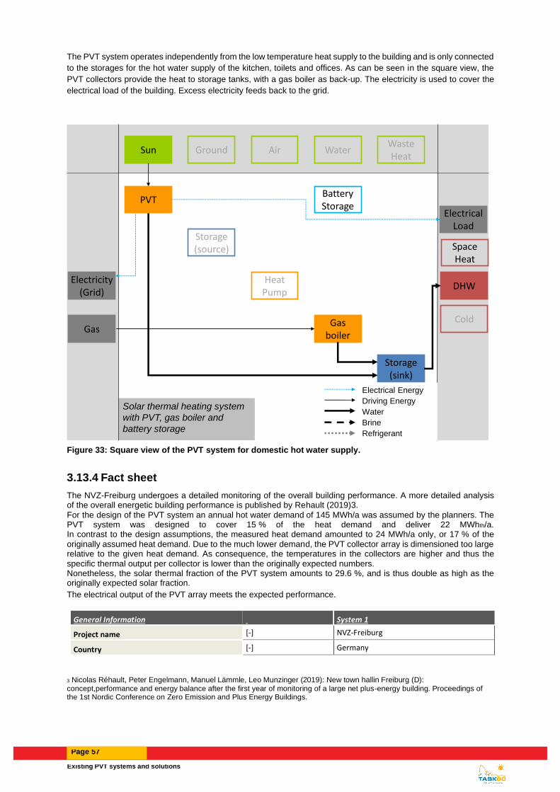
Existing PVT systems and solutions
Page 57
The PVT system operates independently from the low temperature heat supply to the building and is only connected
to the storages for the hot water supply of the kitchen, toilets and offices. As can be seen in the square view, the
PVT collectors provide the heat to storage tanks, with a gas boiler as back-up. The electricity is used to cover the
electrical load of the building. Excess electricity feeds back to the grid.
Solar thermal heating system
with PVT, gas boiler and
battery storage
Heat Pump
Air WaterGround
Storage (source)
Storage (sink)
Space Heat
DHW
Waste Heat
Sun
Gas boiler
ColdGas
Battery Storage
Electrical Load
Electrical Energy
Driving Energy
Water
Brine
Refrigerant
Electricity(Grid)
PVT
Figure 33: Square view of the PVT system for domestic hot water supply.
3.13.4 Fact sheet
The NVZ-Freiburg undergoes a detailed monitoring of the overall building performance. A more detailed analysis of the overall energetic building performance is published by Rehault (2019)3. For the design of the PVT system an annual hot water demand of 145 MWh/a was assumed by the planners. The PVT system was designed to cover 15 % of the heat demand and deliver 22 MWhth/a. In contrast to the design assumptions, the measured heat demand amounted to 24 MWh/a only, or 17 % of the originally assumed heat demand. Due to the much lower demand, the PVT collector array is dimensioned too large relative to the given heat demand. As consequence, the temperatures in the collectors are higher and thus the specific thermal output per collector is lower than the originally expected numbers. Nonetheless, the solar thermal fraction of the PVT system amounts to 29.6 %, and is thus double as high as the originally expected solar fraction.
The electrical output of the PVT array meets the expected performance.
General Information System 1
Project name [-] NVZ-Freiburg
Country [-] Germany
3 Nicolas Réhault, Peter Engelmann, Manuel Lämmle, Leo Munzinger (2019): New town hallin Freiburg (D): concept,performance and energy balance after the first year of monitoring of a large net plus-energy building. Proceedings of the 1st Nordic Conference on Zero Emission and Plus Energy Buildings.

Page 58
City [-] Freiburg
Year of operation start [mm/yyyy] 07.2017
PVT system owner(s) (%) [-] Stadt Freiburg (100%)
PVT system operators(s) [-] Stadt Freiburg
PVT system developer [-] Solvis
Application [-] Water preheating for kitchen and toilets
PLANT CONFIGURATION
Panel model [-] non-commercial
PVT-Collector provider [-] Solvis
Category [-] PVT liquid collector
Type [-] covered
Working Fluid [-] Water/Glycol Mixture
Kind of installation [-] on-roof mounted
Tracking [-] No
System Orientation [E = +90°; S = 0°; W = -90°] [°] -30° - 30°
Tilt angle [hor. = 0°; vert. = 90°] [°] 30°
# of modules [-] 22
Installed collector area (gross) [m²] 51.7
Installed collector area (aperture) [m²] 48.0
Total energy output PVT-collector (Etotal) [kW] 6.8
Seasonal Performance Factor (System) SPFsys [-] -
Thermal Parameters
Solar thermal energy used for [-] Water preheating for kitchen and toilets
Heat demand [kWh/a] 24000
Temperature range (application) [°C] 15 - 65°C
Back-up system [-] gas boiler
Solar thermal energy storage type [-] Water - Short term
Storage Volume [L] 1960
Solar thermal energy to system (Qsol) [kWh/a] 7329
Heat generator energy (Qaux) [kWh/a] 17000
Solar fraction(Qsol/(Qsol+Qaux)) [%] 29%
Electrical Parameters
Module type [-] Monocrystalline
Module efficiency at STC (25°C; 1000W/m²) [%] 15.8
Annual Yield Photovoltaics DC side (Epv) [kWh/a] 5926
Type of inverter [-] Three-phase inverter
AC capacity per inverter [kW] -
# of inverter [-] 1 inverter for PVT array
Inverter provider [-] SolarEdge
Electrical storage type [-] None
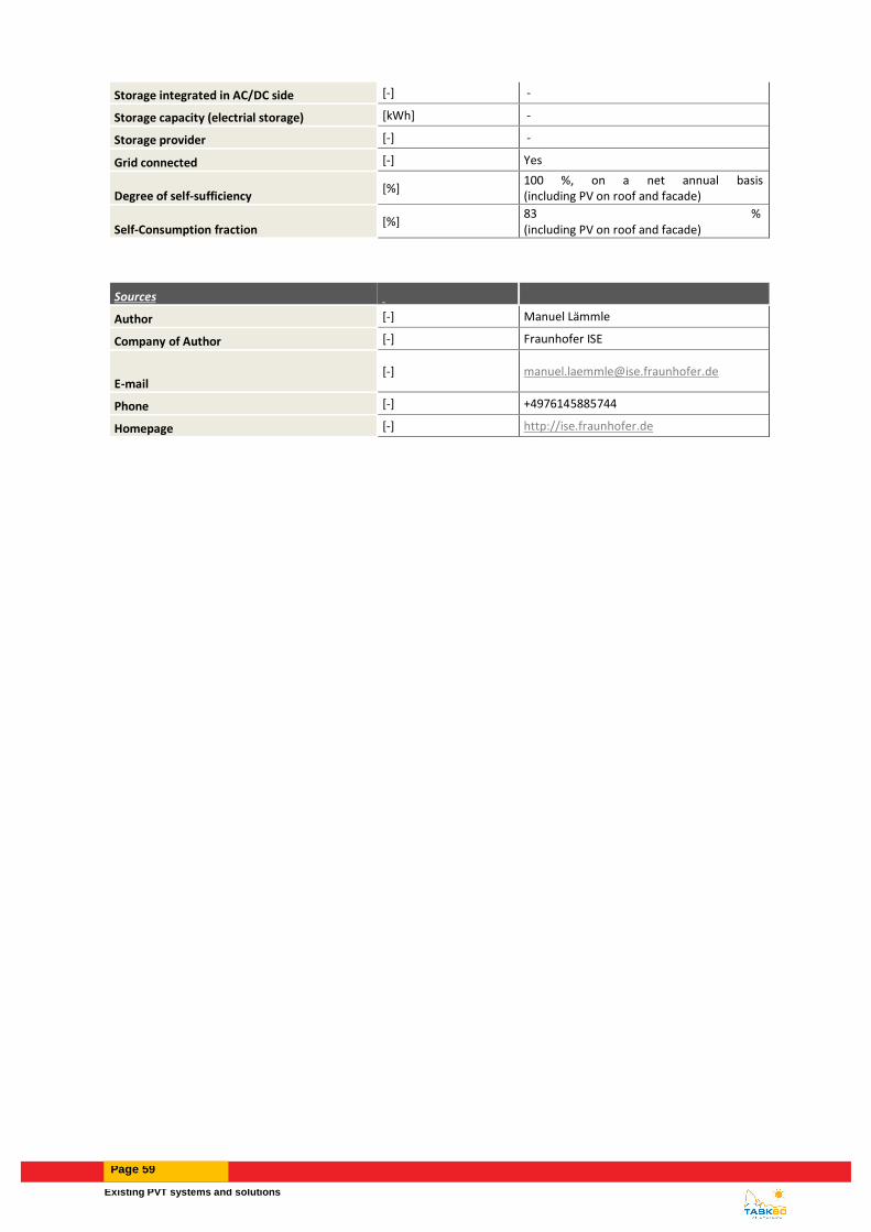
Existing PVT systems and solutions
Page 59
Storage integrated in AC/DC side [-] -
Storage capacity (electrial storage) [kWh] -
Storage provider [-] -
Grid connected [-] Yes
Degree of self-sufficiency [%]
100 %, on a net annual basis (including PV on roof and facade)
Self-Consumption fraction [%]
83 % (including PV on roof and facade)
Sources
Author [-] Manuel Lämmle
Company of Author [-] Fraunhofer ISE
E-mail [-] [email protected]
Phone [-] +4976145885744
Homepage [-] http://ise.fraunhofer.de

Page 60
3.14 Lintharea (sports centre, pool, hotel, restaurant) NÄFELS
3.14.1 Introduction and description
The linth-arena sgu is a sports and meeting centre with swimming pool, fitness rooms, restaurant and hotel. The
heating system is based on a ground water heat pump and a gas boiler for peak load coverage. a PVT is coupled
with a groundwater heat pump. The PVT heat integrated in the system to pre-heat the groundwater and, therefore,
improving the seasonal performance factor (SPF) of the System.
3.14.2 Solar installations
On the roof of the Lintharena there are 178 PVT-Panels (MeyerBurger, 270/900) plus 699 PV-Panels (Typ Sky, 270
Wp). The total electrical output of the plant is 236.79 kWp (PV and PVT). The modules are oriented to the southeast
(-18°) with an inclination angle of 10°.
3.14.3 Heat supply concept and integration of PVT collectors
The PVT – heat is used for pre-heating the groundwater storage. Heat is transferred from the ground water storage
directly to the heat pump and to the overflow basins of the pools. The heat pump generates heat for pools, space
heating and domestic hot water. The heat pump is supported by a gas boiler for the coverage of peak loads.
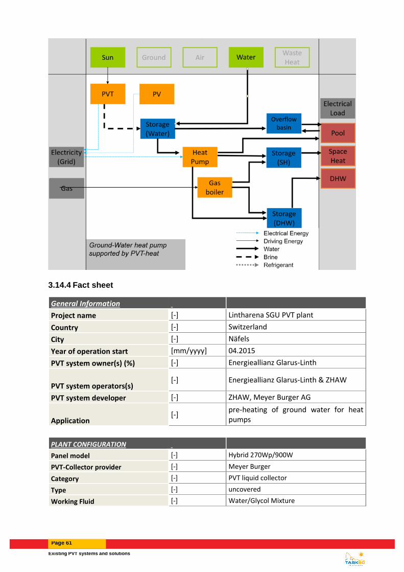
Existing PVT systems and solutions
Page 61
3.14.4 Fact sheet
General Information Project name [-] Lintharena SGU PVT plant
Country [-] Switzerland
City [-] Näfels
Year of operation start [mm/yyyy] 04.2015
PVT system owner(s) (%) [-] Energieallianz Glarus-Linth
PVT system operators(s) [-] Energieallianz Glarus-Linth & ZHAW
PVT system developer [-] ZHAW, Meyer Burger AG
Application [-]
pre-heating of ground water for heat pumps
PLANT CONFIGURATION Panel model [-] Hybrid 270Wp/900W
PVT-Collector provider [-] Meyer Burger
Category [-] PVT liquid collector
Type [-] uncovered
Working Fluid [-] Water/Glycol Mixture

Page 62
Kind of installation [-] on-roof mounted
Tracking [-] No
System Orientation [E = +90°; S = 0°; W = -90°]
[°] 24
Tilt angle [hor. = 0°; vert. = 90°] [°] 10
# of modules [-] 178
Installed collector area (gross) [m²] 292
Installed collector area (aperture) [m²] 269
Total energy output PVT-collector (Etotal)
[kWh] 359.500
Seasonal Performance Factor (System) SPFsys
[-] not known (no use of produced electricity in the building)
Thermal Parameters
Solar thermal energy used for [-]
preheating of groundwater before used in heat pump
Heat demand [kWh/a] 2.717.000
Temperature range (application) [°C] source: 8-13°C
Back-up system [-] gas boiler
Solar thermal energy storage type [-] Water - Short term
Storage Volume [L] cold storage up to 17'500l
Solar thermal energy to system (Qsol) [kWh/a] 129.000
Heat generator energy (Qaux) [kWh/a] 2.717.000
Solar fraction(Qsol/(Qsol+Qaux)) [%] 0
Electrical Parameters
Module type [-] Monocrystalline
Module efficiency at STC (25°C; 1000W/m²)
[%] 16,5
Annual Yield Photovoltaics DC side (Epv)
[kWh/a] 56015,35
Type of inverter [-] Fronius Symo
AC capacity per inverter [kW] 2*15 & 1*17.5 kVA
# of inverter [-] 3
Inverter provider [-] Fronius
Electrical storage type [-] None
Storage integrated in AC/DC side [-]
Storage capacity (electrical storage) [kWh]
Storage provider [-]
Grid connected [-] Yes
Degree of self-sufficiency [%] 0
Self-Consumption fraction [%] 0

Existing PVT systems and solutions
Page 63
Economic Parameters Total investment cost (excl. VAT) [€] 256.193
PVT-collector loop (excl. VAT) [€] 102.390
Solar thermal energy storage (excl. VAT)
[€] 42.413
Inverter (excl. VAT) [€]
Electrical storage (excl. VAT) [€] 0
others (excl. VAT) [€] 111.390
Specific investment cost [€/m²] 877
Calculated solar thermal system life time
[a] 25
Subsidy, € or % of total investment costs
[€/%]
Fuel replaced [-] electricity
Cost for fuel replaced [€/MWhfuel]
Local feed-in tariff [€/MWhelectricity] 165
Sources Author [-] M. Schubert / N. Sperr / J. Rohrer
Company of Author [-] ZHAW - Zurich University of Applied Sciences
E-mail [-]
[email protected]; [email protected]
Phone [-] +41 58 934 52 72
Homepage [-] www.zhaw.ch/iunr/erneuerbareenergien/

Page 64
3.15 FVE - ATLAS O.C. s.r.o.
3.15.1 Introduction and description
The energy system for multi-family house located in Czech Republic was built in 2014. The system consists of
ground source heat pump coupled with unglazed PVT collectors.
Figure 34: PVT system on the roof of the multi-family house (left) and technical room with ground source heat pump and storages (right)
3.15.2 Solar installations
Solar installation consists of 119 PVT collectors (Fototherm) installed on the roof of the building (total collector area, 188 m2; 29.8 kWp electrical output). Aperture area of one PVT collector is 1.58 m2. The PVT collectors are oriented to the southwest (20°) with an inclination angle of 17°.
3.15.3 Heat supply concept and integration of PVT collectors
The PVT collector field operates in three modes based on priority of heat utilization. Heat from PVT collectors is
primary used for DHW preparation (500 l), secondary is the heat used for storage (300 l) before heat pump. If both
requirements are fulfilled the heat from PVT collectors is used for regeneration of boreholes.

Existing PVT systems and solutions
Page 65
3.15.4 Fact sheet
General Information
Project name [-] FVE - ATLAS O.C. s.r.o.
Country [-] Czech republic
City [-] Prerov
Year of operation start [mm/yyyy] 01/2014
PVT system owner(s) (%) [-] ATLAS O.C. s.r.o.
PVT system operators(s) [-] ATLAS O.C. s.r.o.
PVT system developer [-] ATLAS O.C. s.r.o.
Application [-] Multi-family house
PLANT CONFIGURATION

Page 66
Panel model [-] FT250AL
PVT-Collector provider [-] Fototherm
Category [-] PVT liquid collector
Type [-] uncovered
Working Fluid [-] Water/Glycol Mixture
Kind of installation [-] on-roof mounted
Tracking [-] No
System Orientation [E = +90°; S = 0°; W = -90°] [°] 17°
Tilt angle [hor. = 0°; vert. = 90°] [°] 20°
# of modules [-] 119
Installed collector area (gross) [m²] 188
Installed collector area (aperture) [m²] 188
Total energy output PVT-collector (Etotal) [kWh] 52598 (2017)
Seasonal Performance Factor (System) SPFsys [-] -
Thermal Parameters
Solar thermal energy used for [-]
DHW, regeneration of boreholes, source for heat pump
Heat demand [kWh/a] -
Temperature range (application) [°C] -5 to 50°C
Back-up system [-] brine/water heat pump
Solar thermal energy storage type [-] Water - Short term
Storage Volume [L]
boreholes, DHW storage 500 l, source storage 300 l
Solar thermal energy to system (Qsol) [kWh/a] 22085 (2017)
Heat generator energy (Qaux) [kWh/a] -
Electrical Parameters
Module type [-] Polycrystalline
Module efficiency at STC (25°C; 1000W/m²) [%] 15.2
Annual Yield Photovoltaics DC side (Epv) [kWh/a] 30 513 (2017)
Type of inverter [-] -
AC capacity per inverter [kW] -
# of inverter [-] -
Inverter provider [-] -
Electrical storage type [-] None
Storage integrated in AC/DC side [-] -

Existing PVT systems and solutions
Page 67
Storage capacity (electrical storage) [kWh] -
Storage provider [-] -
Grid connected [-] Yes
Degree of self-sufficiency [%] -
Self-Consumption fraction [%] -
Sources
Author [-] Nikola Pokorny
Company of Author [-] UCEEB CTU in Prague
E-mail [-] [email protected]
Phone [-] +420 777 048 835
Homepage [-] www.uceeb.cz

Page 68
3.16 Single-family house SUELLO (LECCO)
3.16.1 Introduction and description
The object concerned is a new single-family house which includes a PVT system, installed in 2016. The heating
and cooling plant includes a reversible heat pump, two storage tanks, 16 PVT modules and two ground heat
exchangers. Moreover, a 16 PV modules plant is installed on the house roof.
Figure 35: View of the PVT system on the roof of the single-family house in Suello (Lecco).
3.16.2 Solar installations
16 PVT collectors (Solink HBK250850) were installed on the pitched roof of the building (total collector area, 26.08 m2; 4 kWp electrical output). The modules are oriented to the south with an inclination angle of 35°. In addition, a PV system with the same orientation comprising 16 modules of the same type, though without heat absorbers, was installed (26.08 m2; 4 kWp).
3.16.3 Heat supply concept and integration of PVT collectors
The heating and cooling supply system is depicted in simplified form in Figure 36. It is based on a reversible heat
pump coupled with the PVT plant or a geothermal heat exchanger (depending on the season). In the summer,
during the day the building is cooled through the reversible heat pump, which is electrically driven by the PVT and
PV plants, while the condenser is connected to one geothermal heat exchanger (total surface of about 20.24 m2).
During the day, PVT modules are cooled by another twin geothermal heat exchanger, while during night the PVT
is used to cool down the cold water storage. In the winter, the heat produced by PVT is used on the evaporator side
of the heat pump.

Existing PVT systems and solutions
Page 69
Figure 36: Visualisation of the PVT system “Suello”.
3.16.4 Fact sheet
General Information
Project name [-] PVT Suello
Country [-] Italy
City [-] 26
Year of operation start [mm/yyyy] 05/2016
PVT system owner(s) (%) [-] Private
PVT system operators(s) [-] Solink
PVT system developer [-] Solink
Application [-] Integration with ground source heat pump
PLANT CONFIGURATION
Panel model [-] HBK250850
PVT-Collector provider [-] Solink
Category [-] PVT liquid collector
Type [-] Unglazed
Working Fluid [-] Water/Glycol Mixture
Kind of installation [-] Roof or façade integration

Page 70
Tracking [-] No
System Orientation [E = +90°; S = 0°; W = -90°] [°] 0°
Tilt angle [hor. = 0°; vert. = 90°] [°] 35°
# of modules [-] 16
Installed collector area (gross) [m²] 26.08
Installed collector area (aperture) [m²] 23.20
Total energy output PVT-collector (Etotal) [kW] 21520
Seasonal Performance Factor (System) SPFsys [-] 2
Thermal Parameters
Solar thermal energy used for [-] Increase heat pump COP
Heat demand [kWh/a] 11750
Temperature range (application) [°C] 0-20
Back-up system [-] water/water heat pump
Solar thermal energy storage type [-] Ground
Storage Volume [L] NA
Solar thermal energy to system (Qsol) [kWh/a] 18345
Heat generator energy (Qaux) [kWh/a] 42840
Solar fraction(Qsol/(Qsol+Qaux)) [%] 30%
Electrical Parameters
Module type [-] Polycrystalline
Module efficiency at STC (25°C; 1000W/m²) [%] 15.35
Annual Yield Photovoltaics DC side (Epv) [kWh/a] 5200
Type of inverter [-] 3Phase
AC capacity per inverter [kW] 8.5
# of inverter [-] 1
Inverter provider [-] ABB
Electrical storage type [-] None
Storage integrated in AC/DC side [-] -
Storage capacity (electrical storage) [kWh] -
Storage provider [-] -
Grid connected [-] Yes
Degree of self-sufficiency [%] 50
Self-Consumption fraction [%] 50
Economic Parameters
Total investment cost (excl. VAT) [€] 39000
PVT-collector loop (excl. VAT) [€] 6400
Solar thermal energy storage (excl. VAT) [€] 8500
Inverter (excl. VAT) [€] 2000
Electrical storage (excl. VAT) [€] 0
others (excl. VAT) [€] 22100
Specific investment cost [€/m²] 1495

Existing PVT systems and solutions
Page 71
Calculated solar thermal system life time [a] 20
Subsidy, € or % of total investment costs [€/%] 0
Fuel replaced [-] Electricity
Cost for fuel replaced [€/MWhfuel] 22
Local feed-in tariff [€/MWhelectricity] 22
Sources
Author [-] Marco Pellegrini
Company of Author [-] University of Bologna
E-mail [-] [email protected]
Phone [-] 0039-051-2093403
Homepage [-]

Page 72
3.17 Multi-family house OBERFELD
3.17.1 Introduction and description
The object Oberfeld is a multi-family house it’s a sustainable and car-free settlement in Ostermundigen near Bern.
The construction project is according to Minergie-P-ECO standard. The whole settlement consists of the three
buildings A, B and C. Each of the three buildings has its own separate heating system consisting of heat pump,
geothermal field and PVT solar system.
Figure 37 : View of the building B (background) in front part of the PVT system on the roof of building C
3.17.2 Solar installation
The entire PVT system is distributed over the different roofs of the buildings. It consists total 799 PVT collectors
and has a total area more than 1300 m2. With this system size the borehole field should be 100% regenerated. The
aim of this P&D project is to gain experience on the earth temperatures with full regeneration over several years.
The PVT collectors are the Meyer Burger Hybrid type 240/90 they are installed flat (0° inclination angle) to maximize
the collector area on the roof.
3.17.3 Heat supply concept and integration of PVT collectors
The heat supply system is depicted in simplified form in Figure 38. As mentioned each building has his own heating
system. The solar heat is used to regenerate the boreholes. A simultaneous operation of regeneration and heat
pump use is possible. In this case the heat pumps benefit from higher fluid temperatures during regeneration
operation. If so the solar heat is used as direct source for the heat pumps. Even though the PVT fluid temperature
is damped first by the borehole field. The maximum temperature allowed to entry the boreholes field is 30°C. It
turned out this being also the achieved temperature by the PVT filed at sunny summer days for this particular
system.

Existing PVT systems and solutions
Page 73
Figure 38 : Visualisation of the PVT system “Oberfeld”
3.17.4 Fact sheet
General Information
Project name [-]
P&D plant "Wohnbaugenossenschaft Oberfeld"
Country [-] CH
City [-] Ostermundigen
Year of operation start [mm/yyyy] 2014-2019
PVT system owner(s) (%) [-] Contractor (utility company)
PVT system operators(s) [-] Contractor
PVT system developer [-]
Contractor, PVT manufacturer, research institute
Application [-]
building complex (3 MFH, in total 100 apartments)
PLANT CONFIGURATION
Panel model [-] Meyer Burger Hybdrid 260/900
PVT-Collector provider [-] Meyer Burger AG
Category [-] PVT liquid collector
Type [-] uncovered

Page 74
Working Fluid [-] Water/Glycol Mixture
Kind of installation [-] on-roof mounted
flat roof
Tracking [-] No
System Orientation [E = +90°; S = 0°; W = -90°]
[°]
Tilt angle [hor. = 0°; vert. = 90°] [°] 0
# of modules [-] 799 (Haus B: 379)
Installed collector area (gross) [m²] 1320 (Haus B: 622)
Installed collector area (aperture) [m²] 1320 (Haus B: 622)
Total energy output PVT-collector (Etotal) [kW]
Seasonal Performance Factor (System) SPFsys
[-] unknown
Thermal Parameters
Solar thermal energy used for [-]
borehole regeneration, direct heat source of heat pump
Heat demand [kWh/a] 436‘000
Temperature range (application)
[°C] corresponding to applications, borehole regeneration maximum inlet temperature 30 °C
Back-up system [-] water/water heat pump
Solar thermal energy storage type [-] Ground
Storage Volume [L] 28 boreholes 200 m each
Solar thermal energy to system (Qsol) [kWh/a] Haus B: 187000-205000
Heat generator energy (Qaux) [kWh/a] 220000
Solar fraction(Qsol/(Qsol+Qaux))
[%] not meaningful for case of borehole regeneration and solar heat as source of heat pump
Borehole regeneration rate
Electrical Parameters
Module type [-] Monocrystalline
Module efficiency at STC (25°C; 1000W/m²)
[%] 15.9
Annual Yield Photovoltaics DC side (Epv) [kWh/a] unknown
Type of inverter [-] unknown
AC capacity per inverter [kW] -
# of inverter [-] Haus B: 7
Inverter provider [-] Solarmax
Electrical storage type [-] None
Storage integrated in AC/DC side [-]
Storage capacity (electrical storage) [kWh]
Storage provider [-]

Existing PVT systems and solutions
Page 75
Grid connected [-] Yes
Degree of self-sufficiency [%] unknown
Self-Consumption fraction [%] unknown
Sources
Author [-] Aleksis Baggenstos
Company of Author [-] SPF Rapperswil
E-mail [-] [email protected]
Phone [-] "+41552224161"
Homepage [-] www.spf.ch

Page 76
3.18 Multi-family house SOTCHA
3.18.1 Introduction and description
One of the first residential complexes in the region of the Alps based on the Minergie-A standard has been
constructed in Scuol (GR). In this complex, which forms an integral part of the new “Monolith” residential district,
three heating systems based on different solar installations were realised in three identical apartment houses.
Buildings A, B and C are structurally identical, have the same orientation and each comprise eight apartments. A
detailed monitoring system was installed that will permit a comparison between the three systems. The mountain
location poses special challenges due to the low outside temperatures, but thanks to the high level of solar
irradiation it also offers advantages for qualifying for the demanding Minergie-A label.
3.18.2 Solar installation
The other properties of the three heat supply systems are as follows:
House A: PV system (130 m2; 21.8 kWp electricity) with electrical storage facility (28 kWh). This building
without regeneration of the ground source serves as the reference system.
House B: In-roof PVT system developed by Caotec (130 m2; 21.8 kWp electricity) with uncovered
rearinsulated PVT collectors. In addition to ground source regeneration via a brine buffer storage unit, the solar
heat can also be used as a direct source for the heat pump and for direct hot water preheating.
House C: Solar thermal installation (40 m2) with “Alpsun Indach” roof-integrated flat-plate collectors from
Caotec. The remainder of the surface of this roof was covered with PV modules (90 m2). The solar heat is primarily
used for providing hot water, with heating support as second priority and borehole regeneration via a brine buffer
storage unit as third priority.
The type of PV modules installed on buildings A and C is Capillary G/G 280W from Sunage. All the solar installations
have a southern orientation.

Existing PVT systems and solutions
Page 77
3.18.3 Heat supply concept and integration of PVT collectors
All three buildings have a power adjustable brine/water heat pump (30 kW heating capacity) that is connected to an
individual geothermal borehole field (five boreholes with a depth of 170 meters). Solar heat can be uses direct
(preheating DHW), heating up brine storage (direct source for hp) and regenerating boreholes. The capacity of each
brine storage unit is 1,000 liters. The capacity of the buffer storage tank for hot water and space heating into which
the solar heat is fed, is 2,000 liters.
Buffer Storage
P&D Project Sotchà, building B, simplif iedOrig: Combined Sol ar Thermal and Ground Source Heat Pum p S ystem - Parall el: SGSHP-P
SHP/P
Energy Carrier
Cold
Sun Ground Air WaterWaste Heat
Heat Pump
Space Heating
DHW
Electrical Energy
Water
Brine
Refrigerant
Electricity (Grid)
Household Electricity
Driving Energy
EGrid,HP
EP
VT
,Gri
d
QHP,WS
QSH
QDHW
PVT
Brine Storage
QPVT,WS
QPVT,LTS
EPVT,HE
EPVT,HP
EGrid,HE
QGS,LTS
QCS,HP
Figure 39: square view sotcha
3.18.4 Fact sheet
General Information
Project name [-] P&D Project "Sotchà"
Country [-] CH
City [-] Scuol
Year of operation start [mm/yyyy] 2015
PVT system owner(s) (%) [-] real estate company
PVT system operators(s) [-] installer
PVT system developer [-] installer, research institute
Application
[-] building complex (1 MFH, 8 appartments)
PLANT CONFIGURATION
Panel model [-] Caotec Ibrido
PVT-Collector provider [-] Caotec

Page 78
Category [-] PVT liquid collector
Type [-] uncovered
Working Fluid [-] Water/Glycol Mixture
Kind of installation [-] roof or facade integration
slanted roof
Tracking [-] No
System Orientation [E = +90°; S = 0°; W = -90°]
[°] 0
Tilt angle [hor. = 0°; vert. = 90°] [°] 45
# of modules [-] 78
Installed collector area (gross) [m²] 130
Installed collector area (aperture) [m²] 130
Total energy output PVT-collector (Etotal)
[kW]
Seasonal Performance Factor (System) SPFsys
[-] unknown
Thermal Parameters
Solar thermal energy used for
[-]
borehole regeneration, direct heat source of heat pump, heat into low-temperature storage tank (brine) source of heat pump, heat into hot water storage tank, heat into space heating storage tank
Heat demand [kWh/a] 48000
Temperature range (application)
[°C] corresponding to applications, borehole regeneration maximum inlet temperature ~20 °C
Back-up system [-] brine/water heat pump
Solar thermal energy storage type [-] Water - Short term
Storage Volume [L] 2000
Solar thermal energy to system (Qsol)
[kWh/a] 17000
Heat generator energy (Qaux) [kWh/a] 52000
Solar fraction(Qsol/(Qsol+Qaux)) [%]
Borehole regeneration rate
Electrical Parameters
Module type [-] Monocrystalline
Module efficiency at STC (25°C; 1000W/m²)
[%] 17.1
Annual Yield Photovoltaics DC side (Epv)
[kWh/a] not known yet
Type of inverter [-] unknown
AC capacity per inverter [kW] 20
# of inverter [-] 1
Inverter provider [-] SMA
Electrical storage type [-] None
Storage integrated in AC/DC side [-]
Storage capacity (electrical storage) [kWh]
Storage provider [-]

Existing PVT systems and solutions
Page 79
Grid connected [-] Yes
Degree of self-sufficiency [%] unknown
Self-Consumption fraction [%] unknown
Sources
Author [-] Aleksis Baggenstos
Company of Author [-] SPF Rapperswil
E-mail [-] [email protected]
Phone [-] "+41552224161"
Homepage [-] www.spf.ch
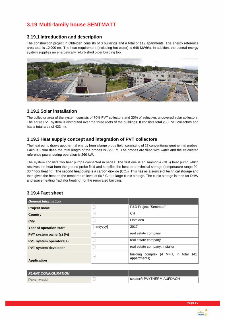
Page 80
3.19 Multi-family house SENTMATT
3.19.1 Introduction and description
The construction project in Obfelden consists of 3 buildings and a total of 119 apartments. The energy reference
area total is 12'900 m2. The heat requirement (including hot water) is 648 MWh/a. In addition, the central energy
system supplies an energetically refurbished older building too.
3.19.2 Solar installation
The collector area of the system consists of 70% PVT collectors and 30% of selective, uncovered solar collectors.
The entire PVT system is distributed over the three roofs of the buildings. It consists total 258 PVT collectors and
has a total area of 423 m2.
3.19.3 Heat supply concept and integration of PVT collectors
The heat pump draws geothermal energy from a large probe field, consisting of 27 conventional geothermal probes.
Each is 270m deep the total length of the probes is 7290 m. The probes are filled with water and the calculated
reference power during operation is 260 kW.
The system consists two heat pumps connected in series. The first one is an Ammonia (NH3) heat pump which
receives the heat from the ground probe field and supplies the heat to a technical storage (temperature range 20-
30 ° floor heating). The second heat pump is a carbon dioxide (CO2). This has as a source of technical storage and
then gives the heat on the temperature level of 60 ° C to a large cubic storage. The cubic storage is then for DHW
and space heating (radiator heating) for the renovated building.
3.19.4 Fact sheet
General Information
Project name [-] P&D Project "Sentmatt"
Country [-] CH
City [-] Obfelden
Year of operation start [mm/yyyy] 2017
PVT system owner(s) (%) [-] real estate company
PVT system operators(s) [-] real estate company
PVT system developer [-] real estate company, installer
Application
[-] building complex (4 MFH, in total 141 appartments)
PLANT CONFIGURATION
Panel model [-] solator® PV+THERM AUFDACH

Existing PVT systems and solutions
Page 81
PVT-Collector provider [-] Solator
Category [-] PVT liquid collector
Type [-] uncovered
Working Fluid [-] Water/Glycol Mixture
Kind of installation [-] on-roof mounted
flat roof
Tracking [-] No
System Orientation [E = +90°; S = 0°; W = -90°]
[°] 0
Tilt angle [hor. = 0°; vert. = 90°] [°] 10
# of modules [-] 258
Installed collector area (gross) [m²] 423
Installed collector area (aperture) [m²] 423
Total energy output PVT-collector (Etotal)
[kW]
Seasonal Performance Factor (System) SPFsys
[-] unknown
Thermal Parameters
Solar thermal energy used for
[-] borehole regeneration, direct heat source of heat pump, heat into hot water storage tank
Heat demand [kWh/a] not known yet
Temperature range (application)
[°C] corresponding to applications, borehole regeneration maximum inlet temperature ~40 °C
Back-up system [-] water/water heat pump
Solar thermal energy storage type [-] Ground
Storage Volume [L] 27 boreholes 270 m each
Solar thermal energy to system (Qsol) [kWh/a] not known yet
Heat generator energy (Qaux) [kWh/a] not known yet
Solar fraction(Qsol/(Qsol+Qaux))
[%] not meaningful for case of borehole regeneration and solar heat as source of heat pump
Electrical Parameters
Module type [-] Monocrystalline
Module efficiency at STC (25°C; 1000W/m²)
[%] 17.1
Annual Yield Photovoltaics DC side (Epv)
[kWh/a] not known yet
Type of inverter [-] unknown
AC capacity per inverter [kW] -
# of inverter [-] -
Inverter provider [-] -
Electrical storage type [-] None

Page 82
Storage integrated in AC/DC side [-]
Storage capacity (electrical storage) [kWh]
Storage provider [-]
Grid connected [-] Yes
Degree of self-sufficiency [%] unknown
Self-Consumption fraction [%] unknown
Sources
Author [-] Aleksis Baggenstos
Company of Author [-] SPF Rapperswil
E-mail [-] [email protected]
Phone [-] "+41552224161"
Homepage [-] www.spf.ch

Existing PVT systems and solutions
Page 83
3.20 Single-family house in WETTSWIL AM ALBIS
3.20.1 Introduction and description
The object concerned is a single-family house with a heated outdoor swimming pool, where an existing heat supply
system based on a heat pump coupled with a ground source was expanded in 2012 by adding a PVT system. The
reason for the integration of the PVT system was an observed cooling of the boreholes.
Figure 40: View of the PVT system on the roof of the single-family house in Wettswil.
3.20.2 Solar installations
28 PVT collectors (Meyer Burger Hybrid 240/900) were installed on the flat roof of the building (total collector area, 45.9 m2; 6.7 kWp electrical output). The modules are oriented to the southeast (30°) with an inclination angle of 10°. In addition, a PV system with the same orientation comprising 10 modules of the same type, though without heat absorbers, was installed (16.4 m2; 2.4 kWp).
3.20.3 Heat supply concept and integration of PVT collectors
The heat supply system is depicted in simplified form in Figure 41. It is based on a heat pump coupled with three
geothermal boreholes, each with a length of 150 metres. In the summer, the building is cooled through free cooling
via the geothermal probes, which are thus partially regenerated. The building also has a wine cellar cooling system,
some of the waste heat from which is used for heating up water, while the remainder is fed into the boreholes.
For the integration of the solar system the boreholes were hydraulically separated. Only two of them are regenerated
via the PVT collectors, and the third is used for free cooling. This means that both functions can be used
simultaneously. When heat is drawn by the heat pump, all three boreholes are used in parallel. The solar heat can
be used for heating the swimming pool in addition to the regeneration of the ground source. The installed hydraulics
would also allow for use of the solar heat as a direct source for the heat pump. This operation mode, however, is
not planned.
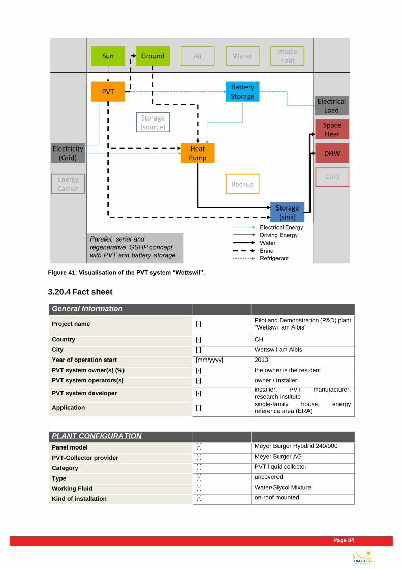
Page 84
Figure 41: Visualisation of the PVT system “Wettswil”.
3.20.4 Fact sheet
General Information
Project name [-] Pilot and Demonstration (P&D) plant "Wettswil am Albis"
Country [-] CH
City [-] Wettswil am Albis
Year of operation start [mm/yyyy] 2013
PVT system owner(s) (%) [-] the owner is the resident
PVT system operators(s) [-] owner / installer
PVT system developer [-] installer, PVT manufacturer, research institute
Application [-] single-family house, energy reference area (ERA)
PLANT CONFIGURATION
Panel model [-] Meyer Burger Hybdrid 240/900
PVT-Collector provider [-] Meyer Burger AG
Category [-] PVT liquid collector
Type [-] uncovered
Working Fluid [-] Water/Glycol Mixture
Kind of installation [-] on-roof mounted
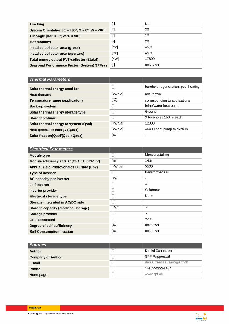
Existing PVT systems and solutions
Page 85
Tracking [-] No
System Orientation [E = +90°; S = 0°; W = -90°] [°] 30
Tilt angle [hor. = 0°; vert. = 90°] [°] 10
# of modules [-] 28
Installed collector area (gross) [m²] 45,9
Installed collector area (aperture) [m²] 45,9
Total energy output PVT-collector (Etotal) [kW] 17800
Seasonal Performance Factor (System) SPFsys [-] unknown
Thermal Parameters
Solar thermal energy used for [-] borehole regeneration, pool heating
Heat demand [kWh/a] not known
Temperature range (application) [°C] corresponding to applications
Back-up system [-] brine/water heat pump
Solar thermal energy storage type [-] Ground
Storage Volume [L] 3 boreholes 150 m each
Solar thermal energy to system (Qsol) [kWh/a] 12300
Heat generator energy (Qaux) [kWh/a] 46400 heat pump to system
Solar fraction(Qsol/(Qsol+Qaux)) [%] -
Electrical Parameters
Module type [-] Monocrystalline
Module efficiency at STC (25°C; 1000W/m²) [%] 14,6
Annual Yield Photovoltaics DC side (Epv) [kWh/a] 5500
Type of inverter [-] transformerless
AC capacity per inverter [kW] -
# of inverter [-] 4
Inverter provider [-] Solarmax
Electrical storage type [-] None
Storage integrated in AC/DC side [-] -
Storage capacity (electrical storage) [kWh] -
Storage provider [-] -
Grid connected [-] Yes
Degree of self-sufficiency [%] unknown
Self-Consumption fraction [%] unknown
Sources
Author [-] Daniel Zenhäusern
Company of Author [-] SPF Rapperswil
E-mail [-] [email protected]
Phone [-] "+41552224142"
Homepage [-] www.spf.ch

Page 86
3.21 Football club house in STENLOESE
3.21.1 Introduction and description
The case described is added to a football club house from the 1970’ties which originally was heated by electricity.
In 2014 the electric radiators were replaced by a low temperature radiator central heating system as first step of a
R&D project aiming at integrating a self-bearing waterproof PVT roof on the building. To supply heat a 25 kW ground
source heat pump was installed.
Figure 42: View of the BIPVT system integrated in the roof of the football club house in Stenloese
3.21.2 Solar installations
24 PVT collectors (Racell SE1100-220 Hercules iTM) were installed as a new roof of the building (total collector area, 165 m2; 24.6 kWp electrical output). The modules are oriented to the south with an inclination angle of 25°. In addition, a PV system with the opposite orientation (North) comprising 24 modules of the same type and visually exactly the same looks, though without heat absorbers, was installed (165 m2; 24.6 kWp).
3.21.3 Heat supply concept and integration of PVT collectors
The heat supply system is depicted in a simplified form in Figure 43. It is based on a heat pump coupled with 1500
m horizontal pipes. The heat is delivered to the 850 l buffertank in 2 different levels – low- and mid temperatures
normally up to 55°C - and high temperature from the super heater part up to 65°C. the buffertank supplies high
temp. heat to the DHW tank and to the central heating system by 25-55°C.
The PVT delivers heat to the buffertank through an integrated heating coil. On warm summerdays the buffertank is
heated up to more than 60°C. In cooler periods with lower PVT temperatures the heat can be supplied to the ground
source pipes to be stored there and used later by the heat pump.
The energy supply of heating and electricity exceeds by far the energy consumption of the building. However, the
reason and concept of combining both horizontal geothermal pipes and PVT is that the ground pipes will function
both as the supply connection for other buildings in the area and also function as storage when there is excess

Existing PVT systems and solutions
Page 87
energy. This concept makes the energy supply to several buildings very flexible and smart control for heating,
cooling and electricity can be implemented.
Figure 43: Visualisation of the PVT system “Stenloese”.
3.21.4 Fact sheet
General Information System 1
Project name [-] Stenløse Footballclub
Country [-] Denmark
City [-] Egedal
Year of operation start [mm/yyyy] 11-2017
PVT system owner(s) (%) [-] Egedal Municipality
PVT system operators(s) [-] Egedal Municipality
PVT system developer [-] EUDP + Racell + Ramboll
Application [-] DHW + roomheating
PLANT CONFIGURATION Panel model [-] SE1100-220 Hercules iTM
PVT-Collector provider [-] RACELL
Category [-] PVT liquid collector
Type [-] uncovered

Page 88
Working Fluid [-] Water/Glycol Mixture
Kind of installation [-] roof or facade integration
Tracking [-] No
System Orientation [E = +90°; S = 0°; W = -90°]
[°] S
Tilt angle [hor. = 0°; vert. = 90°] [°] 25
# of modules [-] 24
Installed collector area (gross) [m²] 165
Installed collector area (aperture) [m²] 154
Total energy output PVT-collector (Etotal) [kWh] 36835
Seasonal Performance Factor (System) SPFsys
[-] 5,1
Thermal Parameters
Solar thermal energy used for [-]
DHW + roomheating in a sports club
Heat demand [kWh/a] 50000
Temperature range (application) [°C] 25 - 60
Back-up system [-] brine/water heat pump
Solar thermal energy storage type [-] Water - Short term
Storage Volume [L] 950
Solar thermal energy to system (Qsol) [kWh/a] 12000
Heat generator energy (Qaux) [kWh/a] 50000
Solar fraction(Qsol/(Qsol+Qaux)) [%] 19
Electrical Parameters
Module type [-] Monocrystalline
Module efficiency at STC (25°C; 1000W/m²) [%] 18,1
Annual Yield Photovoltaics DC side (Epv) [kWh/a] 27200
Type of inverter [-] 3 phase , Symo
AC capacity per inverter [kW] 8,2
# of inverter [-] 3
Inverter provider [-] Fronius
Electrical storage type [-] None
Storage integrated in AC/DC side [-]
Storage capacity (electrial storage) [kWh] None
Storage provider [-] None
Grid connected [-] Yes
Degree of self-sufficiency [%] 24
Self-Consumption fraction [%] 52
Economic Parameters

Existing PVT systems and solutions
Page 89
Total investment cost (excl. VAT) [€] 135000
PVT-collektor loop (excl. VAT) [€] 88000
Solar thermal energy storage (excl. VAT) [€] 10000
Inverter (excl. VAT) [€] 3750
Electrical storage (excl. VAT) [€] 0
others (excl. VAT) [€] 18000
Specific investment cost [€/m²] 1498
Calculated solar thermal system life time [a] 25
Subsidy, € or % of total investment costs [€/%] 60%
Fuel replaced [-] electricity
Cost for fuel replaced [€/MWhfuel] 200
Local feed-in tariff [€/MWhelectricity] 0
Sources Author [-] Niels Radisch
Company of Author [-] Ramboll
E-mail [-] [email protected]
Phone [-] +45 51615754
Homepage [-] www.ramboll.com
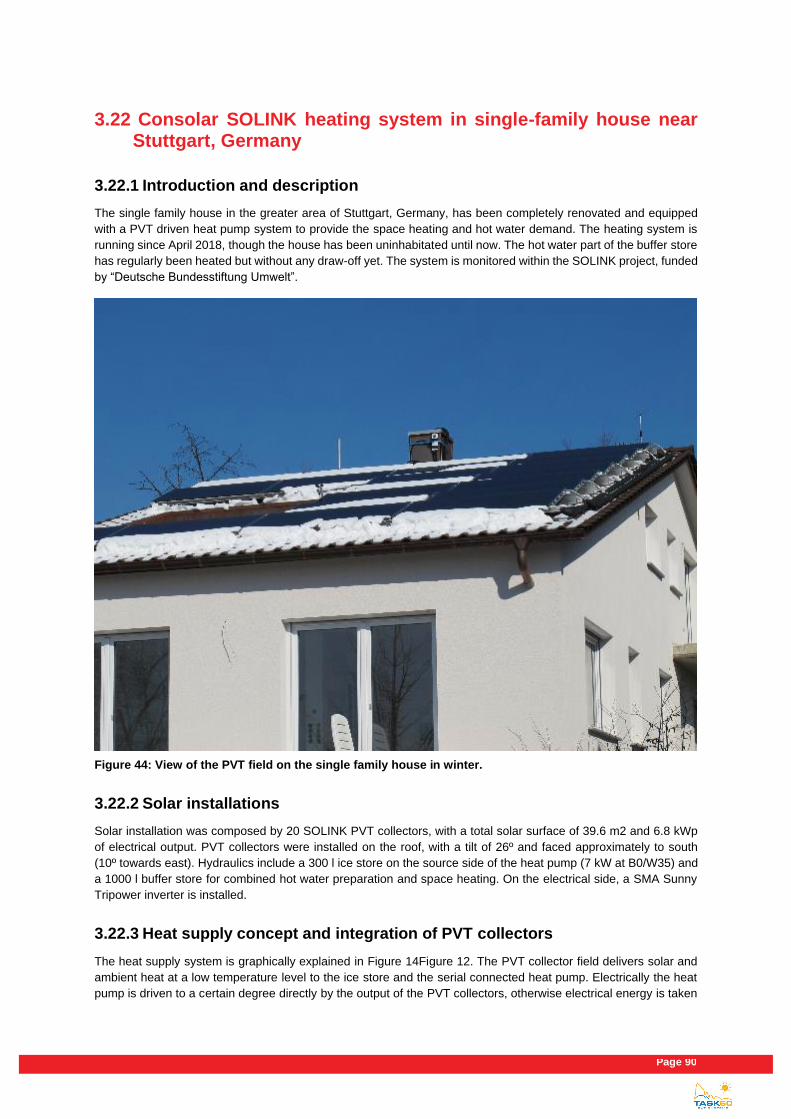
Page 90
3.22 Consolar SOLINK heating system in single-family house near Stuttgart, Germany
3.22.1 Introduction and description
The single family house in the greater area of Stuttgart, Germany, has been completely renovated and equipped
with a PVT driven heat pump system to provide the space heating and hot water demand. The heating system is
running since April 2018, though the house has been uninhabitated until now. The hot water part of the buffer store
has regularly been heated but without any draw-off yet. The system is monitored within the SOLINK project, funded
by “Deutsche Bundesstiftung Umwelt”.
Figure 44: View of the PVT field on the single family house in winter.
3.22.2 Solar installations
Solar installation was composed by 20 SOLINK PVT collectors, with a total solar surface of 39.6 m2 and 6.8 kWp
of electrical output. PVT collectors were installed on the roof, with a tilt of 26º and faced approximately to south
(10º towards east). Hydraulics include a 300 l ice store on the source side of the heat pump (7 kW at B0/W35) and
a 1000 l buffer store for combined hot water preparation and space heating. On the electrical side, a SMA Sunny
Tripower inverter is installed.
3.22.3 Heat supply concept and integration of PVT collectors
The heat supply system is graphically explained in Figure 14Figure 12. The PVT collector field delivers solar and
ambient heat at a low temperature level to the ice store and the serial connected heat pump. Electrically the heat
pump is driven to a certain degree directly by the output of the PVT collectors, otherwise electrical energy is taken
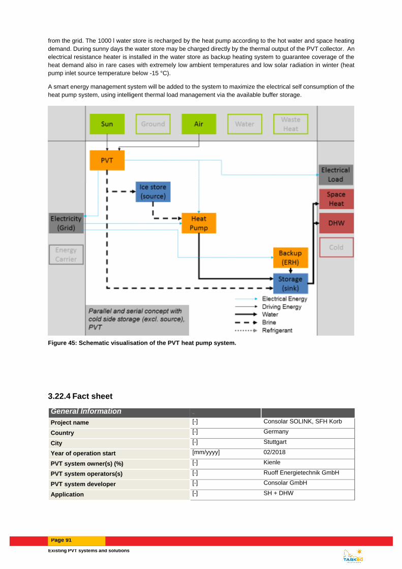
Existing PVT systems and solutions
Page 91
from the grid. The 1000 l water store is recharged by the heat pump according to the hot water and space heating
demand. During sunny days the water store may be charged directly by the thermal output of the PVT collector. An
electrical resistance heater is installed in the water store as backup heating system to guarantee coverage of the
heat demand also in rare cases with extremely low ambient temperatures and low solar radiation in winter (heat
pump inlet source temperature below -15 °C).
A smart energy management system will be added to the system to maximize the electrical self consumption of the
heat pump system, using intelligent thermal load management via the available buffer storage.
Figure 45: Schematic visualisation of the PVT heat pump system.
3.22.4 Fact sheet
General Information
Project name [-] Consolar SOLINK, SFH Korb
Country [-] Germany
City [-] Stuttgart
Year of operation start [mm/yyyy] 02/2018
PVT system owner(s) (%) [-] Kienle
PVT system operators(s) [-] Ruoff Energietechnik GmbH
PVT system developer [-] Consolar GmbH
Application [-] SH + DHW

Page 92
PLANT CONFIGURATION
Panel model [-] Consolar SOLINK
PVT-Collector provider [-] Consolar GmbH
Category [-] PVT liquid collector
Type [-] uncovered
Working Fluid [-] Water/Glycol Mixture
Kind of installation [-] on-roof mounted
Tracking [-] No
System Orientation [E = +90°; S = 0°; W = -90°] [°] 10
Tilt angle [hor. = 0°; vert. = 90°] [°] 26
# of modules 20
Installed collector area (gross) [m²] 39,4
Installed collector area (aperture) [m²] 38,2
Total energy output PVT-collector (Etotal) [kWh] 14380
Seasonal Performance Factor (System) SPFsys [-] 4,7
Thermal Parameters
Solar thermal energy used for [-] SH + DHW @ 50°C (no tapping)
Heat demand [kWh/a] 13580
Temperature range (application) [°C] 25-50
Back-up system [-] electric resistance heater
Solar thermal energy storage type [-] ice store + Water - Short term
Storage Volume [L] 300 + 1000
Solar thermal energy to system (Qsol) [kWh/a] 6250
Heat generator energy (Qaux) [kWh/a]
Solar fraction(Qsol/(Qsol+Qaux)) [%]
Electrical Parameters
Module type [-] Monocrystalline
Module efficiency at STC (25°C; 1000W/m²) [%] 17,5%
Annual Yield Photovoltaics DC side (Epv) [kWh/a] 8130 (AC)
Type of inverter [-] SMA Sunny Tripower
AC capacity per inverter [kW]
# of inverter [-] 1
Inverter provider [-] SMA
Electrical storage type [-] None
Storage integrated in AC/DC side [-]
Storage capacity (electrial storage) [kWh]
Storage provider [-]
Grid connected [-] Yes
Degree of self-sufficiency [%] 16
Self-Consumption fraction [%] 8
Economic Parameters

Existing PVT systems and solutions
Page 93
Total investment cost (excl. VAT) [€] 26,884
PVT-collector loop (excl. VAT) [€] 14,642
Solar thermal energy storage (excl. VAT) [€] Inc. Inverter
Inverter (excl. VAT) [€] 12,242
Electrical storage (excl. VAT) [€] -
others (excl. VAT) [€] -
Specific investment cost [€/m²] 672
Calculated solar thermal system life time [a] 20
Subsidy, € or % of total investment costs [€/%] 7000
Fuel replaced [-] Oil
Cost for fuel replaced [€/MWhfuel] 70
Local feed-in tariff [€/MWhelectricity] 290
Sources
Author [-] Uli Ruoff
Company of Author [-] RUOFF energietechnik GmbH
E-mail [-] [email protected]
Phone [-] +49 7123 93419-0
Homepage [-] www.ruoff-solar.de
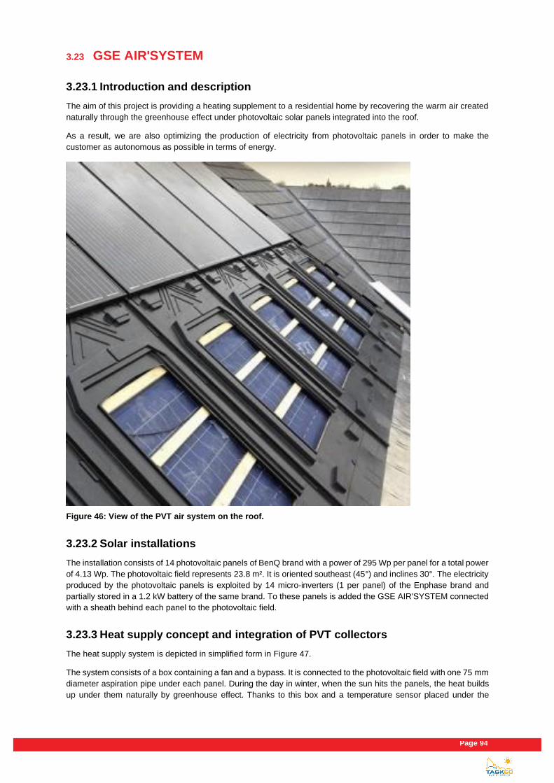
Page 94
3.23 GSE AIR'SYSTEM
3.23.1 Introduction and description
The aim of this project is providing a heating supplement to a residential home by recovering the warm air created
naturally through the greenhouse effect under photovoltaic solar panels integrated into the roof.
As a result, we are also optimizing the production of electricity from photovoltaic panels in order to make the
customer as autonomous as possible in terms of energy.
Figure 46: View of the PVT air system on the roof.
3.23.2 Solar installations
The installation consists of 14 photovoltaic panels of BenQ brand with a power of 295 Wp per panel for a total power
of 4.13 Wp. The photovoltaic field represents 23.8 m². It is oriented southeast (45°) and inclines 30°. The electricity
produced by the photovoltaic panels is exploited by 14 micro-inverters (1 per panel) of the Enphase brand and
partially stored in a 1.2 kW battery of the same brand. To these panels is added the GSE AIR'SYSTEM connected
with a sheath behind each panel to the photovoltaic field.
3.23.3 Heat supply concept and integration of PVT collectors
The heat supply system is depicted in simplified form in Figure 47.
The system consists of a box containing a fan and a bypass. It is connected to the photovoltaic field with one 75 mm
diameter aspiration pipe under each panel. During the day in winter, when the sun hits the panels, the heat builds
up under them naturally by greenhouse effect. Thanks to this box and a temperature sensor placed under the

Existing PVT systems and solutions
Page 95
panels, we take this air under the panels when the temperature below is sufficiently high, and we blow it through
ducts of insufflation in the house of the customer to cover up to 30 % of its heating needs.
During the summer, the bypass closes the house side and opens to a roof hat to allow us to blow the warm air
outward. In this way, the system ventilates the photovoltaic panels to improve their electric production up to 10%.
Solar photovoltaic panels have been integrated in the roof instead of tiles with our integration system GSE IN-ROOF
System. These produce electricity that is fed back into the customer's network via an intelligent energy management
system. This electricity will be stored in a 1.2kW battery if it is not self-consumed by the customer. It will be returned
when the customer needs it, at night for example when the panels do not produce.
Figure 47: Visualisation of the PVT system “GSE AIR'SYSTEM”.
3.23.4 Fact sheet
General Information
Project name [-] GSE AIR'SYSTEM
Country [-] France
City [-] TRAINON
Year of operation start [mm/yyyy] 09/2018
PVT system owner(s) (%) [-] The owner is the resident
PVT system operators(s) [-] Resident
PVT system developer [-] GSE INTEGRATION
Application [-] Single-family house

Page 96
PLANT CONFIGURATION
Panel model [-] BenQ 295w full black
PVT-Collector provider [-] BENQ
Category [-] Ventilated PV with heat recovery
Type [-] covered
Working Fluid [-] Air
Kind of installation [-] roof or facade integration
Tracking [-] Yes
System Orientation [E = +90°; S = 0°; W = -90°] [°] SE = +45°
Tilt angle [hor. = 0°; vert. = 90°] [°] 30°
# of modules [-] 14
Installed collector area (gross) [m²] 23,8
Installed collector area (aperture) [m²] 22,8
Total energy output PVT-collector (Etotal) [kW] 10800
Seasonal Performance Factor (System) SPFsys [-] 4,7
Thermal Parameters
Solar thermal energy used for [-] Air
Heat demand [kWh/a] 12000
Temperature range (application) [°C] 17 - 57°C
Back-up system [-] electrical heating element
Solar thermal energy storage type [-] none
Storage Volume [L] -
Solar thermal energy to system (Qsol) [kWh/a] 6000
Heat generator energy (Qaux) [kWh/a] 4500
Solar fraction(Qsol/(Qsol+Qaux)) [%] 43
Electrical Parameters
Module type [-] Monocrystalline
Module efficiency at STC (25°C; 1000W/m²) [%] 295
Annual Yield Photovoltaics DC side (Epv) [kWh/a] 4820
Type of inverter [-] Microinverter
AC capacity per inverter [kW] 0,25
# of inverter [-] 14
Inverter provider [-] Enphase
Electrical storage type [-] Battery (Lithium)
Storage integrated in AC/DC side [-] DC
Storage capacity (electrial storage) [kWh] 1,2
Storage provider [-] Enphase
Grid connected [-] Yes
Degree of self-sufficiency [%] 47
Self-Consumption fraction [%] 70

Existing PVT systems and solutions
Page 97
Economic Parameters
Total investment cost (excl. VAT) [€] 14600
PVT-collektor loop (excl. VAT) [€] 8600
Solar thermal energy storage (excl. VAT) [€] -
Inverter (excl. VAT) [€] 1600
Electrical storage (excl. VAT) [€] 1500
others (excl. VAT) [€] 2900
Specific investment cost [€/m²] 600
Calculated solar thermal system life time [a] 20
Subsidy, € or % of total investment costs [€/%] 1200€ (8,2%)
Fuel replaced [-]
Cost for fuel replaced [€/MWhfuel] -
Local feed-in tariff [€/MWhelectricity] 17
Sources
Author [-] Gauthier LEVESQUE
Company of Author [-] GSE INTEGRATION
E-mail [-] [email protected]
Phone [-] 06 99 37 97 42
Homepage [-] www.gseintegration.fr

Page 98
3.24 Single-family house in PERTH western Australia
3.24.1 Introduction and description
The object concerned is a single story freestanding family house. The house has incorporated a number of new
features a part of the endeavour to decarbonise the energy supply and make more electrical capacity available for
complete self-sustainability of the domestic load and future electric mobility solutions. Future planning includes
provision for electric car charging and a battery energy storage system. A 3.5 kW rated Sunovate System was
installed in 2018 to provide space heating during winter and electricity for water heating with a dedicated solar PV
element. The Sunovate PVT system includes 6 x 190 W Conergy PV panels.
The house was originally fitted with an electric boosted 3 panel Solarhart 300L SHW, gas space heating and a
ducted reverse cycle air conditioner. In late 2011 a 3.0 kW PV system was fitted which was upgraded to 5.0 kW
together with the removal of the aged solar hot water. Water heating was replaced with a larger 315L dual element
electric resistance storage unit. The gas heating was decommissioned and the gas utility service disconnected. The
existing ducted air conditioning system (which failed) was replaced with a smaller split reverse cycle air conditioning
system and the ducting modified and repurposed for integrating the PVT system.
Figure 48: View of the PVT system on the roof of the single story family house in Perth.

Existing PVT systems and solutions
Page 99
3.24.2 Solar installations
6 PVT collectors (Conergy 190M) were installed on the flat roof of the building (total collector area, 7.59 m2; 1.14 kWe electrical output). The modules are oriented to the northwest (45°) with an inclination angle of 22.5°. In addition, a PV system with the same orientation comprising 26 modules of the same type, though without heat absorbers, was installed (32.9 m2; 4.94 kWe).
3.24.3 Heat supply concept and integration of PVT collectors
The heat supply system is depicted in simplified form in Figure 49. It is based on a simple electric resistance hot
water load for preheating the large 315L hot water storage tank and simple closed loop air flow circuit for winter
space heating. Excess heat in summer is discharge directly to atmosphere in an open loop mode to increase PV
performance.
Water heating services are backed up by the grid through a separate electric resistance heater on timer. Space
heating serviced are backed up by grid connected split reverse cycle air-conditioner.
Figure 49: Visualisation of the Basic PVT system “South Perth - Domestic”.
3.24.4 Fact sheet
General Information
Project name [-] Sunovate Domestic Pilot and Demonstration (P&D) plant
Country [-] AU
City [-] South Perth Western Australia
Year of operation start [mm/yyyy] 06/2018

Page 100
PVT system owner(s) (%) [-] the owner is the resident
PVT system operators(s) [-] owner / installer
PVT system developer [-] Sunovate
Application [-] Single story -family house
PLANT CONFIGURATION
Panel model [-] Conergy 190M
PVT-Collector provider [-] Sunovate Pty Ltd
Category [-] PVT air collector
Type [-] WISP
Working Fluid [-] Air
Kind of installation [-] on-roof frame mounted
Tracking [-] No
System Orientation [E = +90°; S = 0°; W = -90°] [°] -45
Tilt angle [hor. = 0°; vert. = 90°] [°] 22.5
# of modules [-] 6
Installed collector area (gross) [m²] 7,5
Installed collector area (aperture) [m²] 7,2
Total energy output PVT-collector (Etotal) [kW] 3,5
Seasonal Performance Factor (System) SPFsys [-] unknown
Thermal Parameters
Solar thermal energy used for [-] Hot water, space heating
Heat demand [kWh/a] not known
Temperature range (application) [°C] corresponding to applications
Back-up system
[-]
Grid connected electric resistance heater (hot water service) Grid Connected air sourced heat pump (space heating)
Solar thermal energy storage type [-]
315L insulated domestic hot water tank. Building fabric for space heating
Storage Volume [L]
315L insulated tank,
Solar thermal energy to system (Qsol) [kWh/a] not yet known
Heat generator energy (Qaux) [kWh/a] not yet known
Solar fraction(Qsol/(Qsol+Qaux)) [%] -
Electrical Parameters
Module type [-] Monocrystalline
Module efficiency at STC (25°C; 1000W/m²) [%] 14,7
Annual Yield Photovoltaics DC side (Epv) [kWh/a] 4500
Type of inverter [-] DC Switched Direct Connect
AC capacity per inverter [kW] -
# of inverter [-] -
Inverter provider [-] -
Electrical storage type [-] -

Existing PVT systems and solutions
Page 101
Storage integrated in AC/DC side [-] -
Storage capacity (electrical storage) [kWh] -
Storage provider [-] -
Grid connected [-] Yes
Degree of self-sufficiency [%] unknown
Self-Consumption fraction [%] unknown
Economic Parameters
Total investment cost (excl. VAT) [€] -
PVT-collector loop (excl. VAT) [€] -
Solar thermal energy storage (excl. VAT) [€] -
Inverter (excl. VAT) [€] -
Electrical storage (excl. VAT) [€] -
others (excl. VAT) [€] -
Specific investment cost [€/m²] -
Calculated solar thermal system life time [a] -
Subsidy, € or % of total investment costs [€/%] -
Fuel replaced [-] -
Cost for fuel replaced [€/MWhfuel] -
Local feed-in tariff [€/MWhelectricity] -
Sources
Author [-] Glen Ryan
Company of Author [-] Sunovate
E-mail [-] [email protected]
Phone [-] +61 (0) 400012620
Homepage [-] www.sunovate.com.au

Page 102
3.25 Office building (Specific)
3.25.1 Introduction and description
The Active Office at Swansea University is the UK’s first energy-positive office building. The office employs an
evacuated-tube PVT array on the south facing façade, a PV array on the roof, lithium ion batteries and an air source
heat pump. The PVT array is shown in Figure 50.
Figure 50: The evacuated tube PVT array (Virtu PVT by Naked Energy) on the south facing façade of the Active Office building at the University of Swansea.

Existing PVT systems and solutions
Page 103
3.25.2 Solar installations
40 PVT collectors (VirtuPVT by Naked Energy) were installed on the southern facing facade of the building (total aperture area, 16 m2; thermal output, 11 kWp; electrical output, 2.8 kWp). In addition, a 22kWp CIGS PV array was installed on the roof (not PVT).
3.25.3 Heat supply concept and integration of PVT collectors
The heat supply system is depicted in simplified form in Figure 51. Heat is supplied by both the PVT array and an
air source heat pump in parallel.
Figure 51: Visualisation of the PVT system at the Specific Active Office in Swansea, UK.
3.25.4 Fact sheet
General Information
Project name [-] Active Office
Country [-] UK
City [-] Swansea
Year of operation start [mm/yyyy] 2018
PVT system owner(s) (%) [-] University of Swansea
PVT system operators(s) [-] University of Swansea
PVT system developer [-] Naked Energy Ltd/Pursey and Bal/SPECIFIC
Application [-] Energy-positive office building
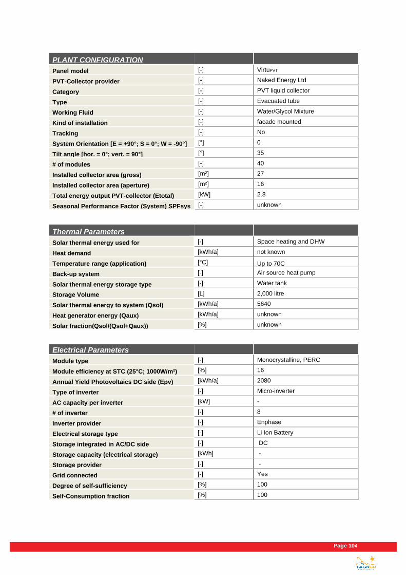
Page 104
PLANT CONFIGURATION
Panel model [-] VirtuPVT
PVT-Collector provider [-] Naked Energy Ltd
Category [-] PVT liquid collector
Type [-] Evacuated tube
Working Fluid [-] Water/Glycol Mixture
Kind of installation [-] facade mounted
Tracking [-] No
System Orientation [E = +90°; S = 0°; W = -90°] [°] 0
Tilt angle [hor. = 0°; vert. = 90°] [°] 35
# of modules [-] 40
Installed collector area (gross) [m²] 27
Installed collector area (aperture) [m²] 16
Total energy output PVT-collector (Etotal) [kW] 2.8
Seasonal Performance Factor (System) SPFsys [-] unknown
Thermal Parameters
Solar thermal energy used for [-] Space heating and DHW
Heat demand [kWh/a] not known
Temperature range (application) [°C] Up to 70C
Back-up system [-] Air source heat pump
Solar thermal energy storage type [-] Water tank
Storage Volume [L] 2,000 litre
Solar thermal energy to system (Qsol) [kWh/a] 5640
Heat generator energy (Qaux) [kWh/a] unknown
Solar fraction(Qsol/(Qsol+Qaux)) [%] unknown
Electrical Parameters
Module type [-] Monocrystalline, PERC
Module efficiency at STC (25°C; 1000W/m²) [%] 16
Annual Yield Photovoltaics DC side (Epv) [kWh/a] 2080
Type of inverter [-] Micro-inverter
AC capacity per inverter [kW] -
# of inverter [-] 8
Inverter provider [-] Enphase
Electrical storage type [-] Li Ion Battery
Storage integrated in AC/DC side [-] DC
Storage capacity (electrical storage) [kWh] -
Storage provider [-] -
Grid connected [-] Yes
Degree of self-sufficiency [%] 100
Self-Consumption fraction [%] 100

Existing PVT systems and solutions
Page 105
Economic Parameters
Total investment cost (excl. VAT) [€] -
PVT-collector loop (excl. VAT) [€] -
Solar thermal energy storage (excl. VAT) [€] -
Inverter (excl. VAT) [€] -
Electrical storage (excl. VAT) [€] -
others (excl. VAT) [€] -
Specific investment cost [€/m²] -
Calculated solar thermal system life time [a] -
Subsidy, € or % of total investment costs [€/%] -
Fuel replaced [-] -
Cost for fuel replaced [€/MWhfuel] -
Local feed-in tariff [€/MWhelectricity] -
Sources
Author [-] Alexander Mellor
Company of Author [-] Naked Energy Ltd
E-mail [-] [email protected]
Phone [-] " +44 1293 541449 "
Homepage [-] https://www.nakedenergy.co.uk

Page 106
3.26 Henri Willig cheese factory
3.26.1 Introduction and description
The object concerned is a food industry factory in Katwoude, the Netherlands. The system has been operational
since July 2017, where it produces both heat and electricity to meet portion of their daily demand around 8 m3 at
45 ℃. Hot water is needed only 5 days a week on average for cheese producing equipment. The project was
qualified for the SDE+ subsidy in the Netherlands on both heat and electricity generation.
Figure 52: View of the PVT system on the roof of Henri Willig cheese factory in Katwoude, the Netherlands.
3.26.2 Solar installations
88 low C-PVT collectors (Solarus PowerCollertorTM) were installed on the flat roof of the building with a total collector area of 226.2 m2, being divided in 22 kWpelect and 110kWpth. The modules are oriented to the southeast (20°) with an inclination angle of 10°.
3.26.3 Heat supply concept and integration of PVT collectors
The heat supply system is depicted in simplified form in Figure 53. 110 kWp system pre-heats the tank up to 30 ℃
in winter and 75 ℃ in summer. An 8 m3 hygienic tank is used in between the collectors and the inline gas boiler
units to deliver heat. A mixing valve at the outlet of the tank ensures that water is delivered at temperatures around
45 ℃. A 22 kWp electrical system with module level optimization is connected and the energy produced is
consumed by the building. In 2018 the collectors have supplied close to 54 MWh of heat and 15 MWh of electricity.
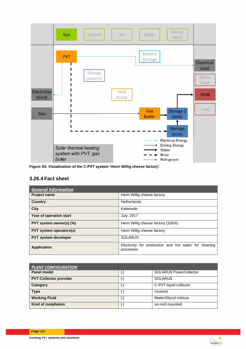
Existing PVT systems and solutions
Page 107
Figure 53: Visualisation of the C-PVT system ‘Henri Willig cheese factory’.
3.26.4 Fact sheet
General Information
Project name Henri Willig cheese factory
Country Netherlands
City Katwoude
Year of operation start July, 2017
PVT system owner(s) (%) Henri Willig cheese factory (100%)
PVT system operators(s) Henri Willig cheese factory
PVT system developer SOLARUS
Application Electricity for production and hot water for cleaning processes
PLANT CONFIGURATION
Panel model [-] SOLARUS PowerCollector
PVT-Collector provider [-] SOLARUS
Category [-] C-PVT liquid collector
Type [-] covered
Working Fluid [-] Water/Glycol mixture
Kind of installation [-] on-roof mounted

Page 108
Tracking [-] No
System Orientation [E = +90°; S = 0°; W = -90°] [°] 20
Tilt angle [hor. = 0°; vert. = 90°] [°] 10
# of modules [-] 88
Installed collector area (gross) [m²] 226.16
Installed collector area (aperture) [m²] 203.28
Total energy output PVT-collector (Etotal) [kWh] 68539
Seasonal Performance Factor (System) SPFsys [-] unknown
Thermal Parameters
Solar thermal energy used for [-] Cheese production process
Heat demand [kWh/a] NA
Temperature range (application) [°C] 45℃
Back-up system [-] gas boiler
Solar thermal energy storage type [-] Water - Short term
Storage Volume [L] 8000
Solar thermal energy to system (Qsol) [kWh/a] 53687 (at the HX)
Heat generator energy (Qaux) [kWh/a] Not available
Solar fraction(Qsol/(Qsol+Qaux)) [%] Not available
Electrical Parameters
Module type [-] Monocrystalline
Module efficiency at STC (25 °C; 1000 W/m²) [%] 9.73
Annual Yield Photovoltaics DC side (Epv) [kWh/a] 14852 (AC side)
Type of inverter [-] 2 string inverters
AC capacity per inverter [kW] 12.5 and 10
# of inverter [-] 2
Inverter provider [-] SolarEdge
Electrical storage type [-] None
Storage integrated in AC/DC side [-] -
Storage capacity (electrical storage) [kWh] -
Storage provider [-] -
Grid connected [-] Yes
Degree of self-sufficiency [%] NA
Self-Consumption fraction [%] 100% AS the PV does not even meet their base load
Economic Parameters
Total investment cost (excl. VAT) [€] NA
PVT-collector loop (excl. VAT) [€] -
Solar thermal energy storage (excl. VAT) [€] NA
Inverter (excl. VAT) [€] -
Electrical storage (excl. VAT) [€] NA

Existing PVT systems and solutions
Page 109
others (excl. VAT) [€] -
Specific investment cost [€/m²] NA
Calculated solar thermal system life time [a] 25
Subsidy, € or % of total investment costs [€/%] SDE+ for 15 years
Fuel replaced [-] Electricity & gas
Cost for fuel replaced [€/MWhfuel] NA
Local feed-in tariff [€/MWhelectricity] NA
Sources
Author [-] Diogo Cabral
Company of Author [-] Solarus Sunpower
E-mail [-] [email protected]
Phone [-] +46 76 900 44 35
Homepage [-] www.solarus.com

Page 110
3.27 GreenTEC Campus in Enge-Sande
3.27.1 Introduction and description
SunOyster Systems GmbH (SOS) develops the SunOyster, a concentrating solar technology for the co-generation
of power and heat (CPVT). The primary concentration is by standard parabolic mirrors and the secondary
concentration by tailor-made lenses, the SunOyster Crystals.
The building is the office and factory for the SunOyster receiver production which was promoted under the SME
instrument of the European Union. It is a former military building which is forming part of the GreenTEC Campus in
Enge-Sande, Northern Frisia, 150 km North of Germany.
3.27.2 Solar installations
The solar installation consists of one SunOyster 16 hybrid pvplus.
The SunOyster 16 consists of two parabolic mirrors of approx. 8 m² gross mirror surface which are tracking the
sun bi-axially all day, concentrating the direct radiation on a focus line. In case of storm, the SunOyster closes into
a secure flat position, the Oystering position, in which the machines survived already various heavy storm.
In the focus line, two hybrid receivers of the pre-series generate at the same time electricity and heat. The electric
output is 3.2 kW p and the parallel thermal output 6 kW of heat. With some further optimization, the SunOyster 16
from serial production shall have 4.7 kW p and 7.5 kW thermal power.
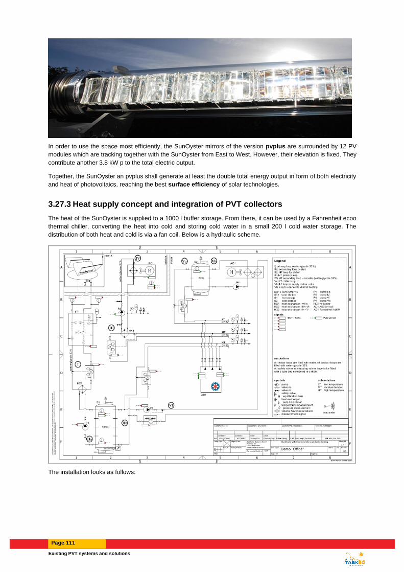
Existing PVT systems and solutions
Page 111
In order to use the space most efficiently, the SunOyster mirrors of the version pvplus are surrounded by 12 PV
modules which are tracking together with the SunOyster from East to West. However, their elevation is fixed. They
contribute another 3.8 kW p to the total electric output.
Together, the SunOyster an pvplus shall generate at least the double total energy output in form of both electricity
and heat of photovoltaics, reaching the best surface efficiency of solar technologies.
3.27.3 Heat supply concept and integration of PVT collectors
The heat of the SunOyster is supplied to a 1000 l buffer storage. From there, it can be used by a Fahrenheit ecoo
thermal chiller, converting the heat into cold and storing cold water in a small 200 l cold water storage. The
distribution of both heat and cold is via a fan coil. Below is a hydraulic scheme.
The installation looks as follows:

Page 112
3.27.4 Fact sheet
General Information
Project name [-] SOcool Office
Country [-] D
City [-] 25917 Enge-Sande, Schleswig-Holstein (150 km North of Hamburg)
Year of operation start [mm/yyyy] 07/2018
PVT system owner(s) (%) [-] SunOyster Systems (SOS)
PVT system operators(s) [-] SOS
PVT system developer [-] SOS
Application [-] Solar thermal cooling and heating of small office
PLANT CONFIGURATION
Panel model [-] SunOyster 16 hybrid pvplus
PVT-Collector provider [-] SunOyster Systems
Category [-] CPVT liquid collector
Type [-] Concentrating
Working Fluid [-] Water/Glycol Mixture
Kind of installation [-] Ground-installation
Tracking [-] Yes, bi-axial
System Orientation [E = +90°; S = 0°; W = -90°] [°] [-]
Tilt angle [hor. = 0°; vert. = 90°] [°] 17° of pvplus
# of modules [-] 2 receivers, 12 PV modules
Installed collector area (gross) [m²] 15 for mirrors, 19.2 for PV
Installed collector area (aperture) [m²] 34.2

Existing PVT systems and solutions
Page 113
Total energy output PVT-collector (Etotal) [kWh] Measurement not completed
Seasonal Performance Factor (System) SPFsys [-] Measurement not completed
Thermal Parameters
Solar thermal energy used for [-] Solar thermal cooling or heating
Heat demand [kWh/a] Measurement not completed
Temperature range (application) [°C] 60 for heating, >=70 for cooling
Back-up system [-] District heating, none for cooling
Solar thermal energy storage type [-] Steel tanks with water
Storage Volume [L] 1000 l for heat, 200 l for cold
Solar thermal energy to system (Qsol) [kWh/a] Measurement not completed
Heat generator energy (Qaux) [kWh/a] Measurement not completed
Solar fraction(Qsol/(Qsol+Qaux)) [%] Measurement not completed
Electrical Parameters
Module type [-] SunOyster receivers
Module efficiency at STC (25°C; 1000W/m²) [%]
21,3 pre-series, expected 30% series production
Annual Yield Photovoltaics DC side (Epv) [kWh/a] Measurement not completed
Type of inverter [-] transformerless
AC capacity per inverter [kW] 3.6 and 4.2 kW
# of inverter [-] 2
Inverter provider [-] ABB
Electrical storage type [-] None
Storage integrated in AC/DC side [-] -
Storage capacity (electrical storage) [kWh] -
Storage provider [-] -
Grid connected [-] Yes
Degree of self-sufficiency [%] Measurement not completed
Self-Consumption fraction [%] Measurement not completed
Sources
Author [-] Dr. Carsten Corino
Company of Author [-] SOS
E-mail [-] [email protected]
Phone [-] 0049 4101 8548181
Homepage [-] www.sunoyster.com

Page 114
3.28 Pilot PVT plant Cittadella Universitaria
3.28.1 Introduction and description
The solar plant is installed in the “Cittadella Universitaria” (i.e. the campus of University of Catania), Catania, Italy
(Lat.37.55N, Long.14.29E), on the terrace of building 13.
This is a pilot plant, which has the main scope to evaluate the performance of a PVT system under different
operating conditions, as well as to compare the experimental data with the results carried out by numerical
simulation on such PVT plant. The design of the PVT plant allows to analyze different electrical and hydraulic
configurations (e.g., it is possible to have an electrical series connections and a parallel hydraulic connection). The
thermal load can be modified to simulate different profiles of energy demands.
Figure 54: View of the PVT system at the University of Catania.
3.28.2 Solar installations
Two PV/T collectors (Dualsun wave 250/880) are installed on the flat roof of the building (total collector area, 3.32
m2; 0.5 kWp electrical output). The modules are south oriented (azimuth angle = 0°) and the tilt angle is equal to
25° (the tilt angle can be changed manually).
3.28.3 Heat supply concept and integration of PVT collectors
The scheme of the hydronic section of the PVT plant is reported in Figure 38.
The position of the sensors for the monitoring of fluid temperatures and flow rates are also showed. .
Figure 55: Scheme of the hydronic section of the PV/T plant with the measured variables
The main components of the plant are: two PV/T modules; a solar thermal tank ( capacity 185 litre ), a water
pump, a dry cooler and the network tubes.
The dry cooler has the function to mimic the domestic hot water demand.
The measured variables are the temperatures of the fluid at the inlet and outlet of each PVT modules, namely TMi,in
and TMi,out, at the inlet and outlet of the thermal solar tank, TST,in and TST,out, at the bottom and the top of the solar
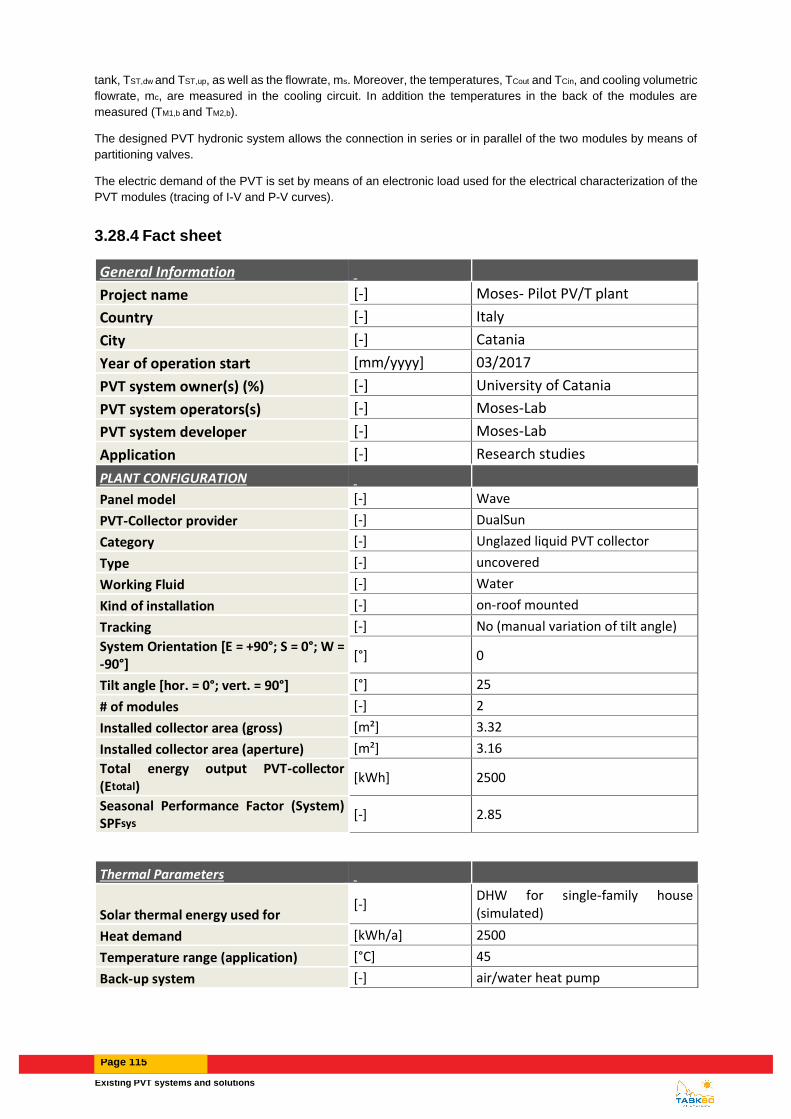
Existing PVT systems and solutions
Page 115
tank, TST,dw and TST,up, as well as the flowrate, ms. Moreover, the temperatures, TCout and TCin, and cooling volumetric
flowrate, mc, are measured in the cooling circuit. In addition the temperatures in the back of the modules are
measured (TM1,b and TM2,b).
The designed PVT hydronic system allows the connection in series or in parallel of the two modules by means of
partitioning valves.
The electric demand of the PVT is set by means of an electronic load used for the electrical characterization of the
PVT modules (tracing of I-V and P-V curves).
3.28.4 Fact sheet
General Information
Project name [-] Moses- Pilot PV/T plant
Country [-] Italy
City [-] Catania
Year of operation start [mm/yyyy] 03/2017
PVT system owner(s) (%) [-] University of Catania
PVT system operators(s) [-] Moses-Lab
PVT system developer [-] Moses-Lab
Application [-] Research studies
PLANT CONFIGURATION
Panel model [-] Wave
PVT-Collector provider [-] DualSun
Category [-] Unglazed liquid PVT collector
Type [-] uncovered
Working Fluid [-] Water
Kind of installation [-] on-roof mounted
Tracking [-] No (manual variation of tilt angle)
System Orientation [E = +90°; S = 0°; W = -90°]
[°] 0
Tilt angle [hor. = 0°; vert. = 90°] [°] 25
# of modules [-] 2
Installed collector area (gross) [m²] 3.32
Installed collector area (aperture) [m²] 3.16
Total energy output PVT-collector (Etotal)
[kWh] 2500
Seasonal Performance Factor (System) SPFsys
[-] 2.85
Thermal Parameters
Solar thermal energy used for [-]
DHW for single-family house (simulated)
Heat demand [kWh/a] 2500
Temperature range (application) [°C] 45
Back-up system [-] air/water heat pump

Page 116
Solar thermal energy storage type [-] Water - Short term
Storage Volume [L] 189
Solar thermal energy to system (Qsol) [kWh/a] 1450
Heat generator energy (Qaux) [kWh/a] 1050
Solar fraction(Qsol/(Qsol+Qaux)) [%] 58
Electrical Parameters
Module type [-] Monocrystalline
Module efficiency at STC (25°C; 1000W/m²)
[%] 15.4
Annual Yield Photovoltaics DC side (Epv) [kWh/a] 1040
Type of inverter [-]
AC capacity per inverter [kW]
# of inverter [-]
Inverter provider [-]
Electrical storage type [-] None
Storage integrated in AC/DC side [-]
Storage capacity (electrical storage) [kWh]
Storage provider [-]
Grid connected [-] No
Degree of self-sufficiency [%] unknown
Self-Consumption fraction [%] unknown
Economic Parameters
Total investment cost (excl. VAT) [€] 10000
PVT-collector loop (excl. VAT) [€] 3500
Solar thermal energy storage (excl. VAT) [€] 1500
Inverter (excl. VAT) [€]
Electrical storage (excl. VAT) [€]
others (excl. VAT) [€] 5000
Specific investment cost [€/m²] 3125
Calculated solar thermal system life time [a] 20
Subsidy, € or % of total investment costs [€/%]
Fuel replaced [-] electricity
Cost for fuel replaced [€/MWhfuel] 250
Local feed-in tariff [€/MWhelectricity]
Sources
Author [-] A. Gagliano - G. M. Tina
Company of Author [-] DIEEI - University of Catania
E-mail [-]

Existing PVT systems and solutions
Page 117
Phone [-] +393204332228
Homepage [-] http://moses.pvt.dieei.unict.it:8081
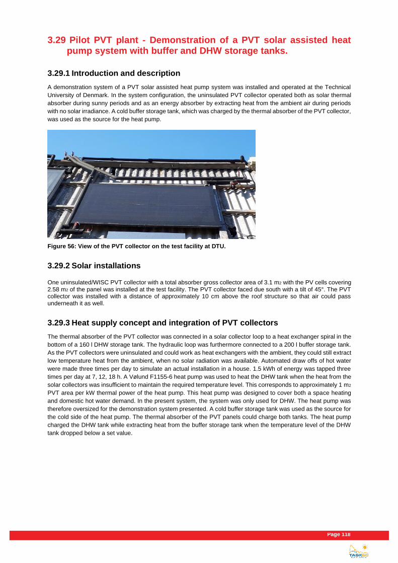
Page 118
3.29 Pilot PVT plant - Demonstration of a PVT solar assisted heat pump system with buffer and DHW storage tanks.
3.29.1 Introduction and description
A demonstration system of a PVT solar assisted heat pump system was installed and operated at the Technical
University of Denmark. In the system configuration, the uninsulated PVT collector operated both as solar thermal
absorber during sunny periods and as an energy absorber by extracting heat from the ambient air during periods
with no solar irradiance. A cold buffer storage tank, which was charged by the thermal absorber of the PVT collector,
was used as the source for the heat pump.
Figure 56: View of the PVT collector on the test facility at DTU.
3.29.2 Solar installations
One uninsulated/WISC PVT collector with a total absorber gross collector area of 3.1 m2 with the PV cells covering 2.58 m2 of the panel was installed at the test facility. The PVT collector faced due south with a tilt of 45°. The PVT collector was installed with a distance of approximately 10 cm above the roof structure so that air could pass underneath it as well.
3.29.3 Heat supply concept and integration of PVT collectors
The thermal absorber of the PVT collector was connected in a solar collector loop to a heat exchanger spiral in the
bottom of a 160 l DHW storage tank. The hydraulic loop was furthermore connected to a 200 l buffer storage tank.
As the PVT collectors were uninsulated and could work as heat exchangers with the ambient, they could still extract
low temperature heat from the ambient, when no solar radiation was available. Automated draw offs of hot water
were made three times per day to simulate an actual installation in a house. 1.5 kWh of energy was tapped three
times per day at 7, 12, 18 h. A Vølund F1155-6 heat pump was used to heat the DHW tank when the heat from the
solar collectors was insufficient to maintain the required temperature level. This corresponds to approximately 1 m2
PVT area per kW thermal power of the heat pump. This heat pump was designed to cover both a space heating
and domestic hot water demand. In the present system, the system was only used for DHW. The heat pump was
therefore oversized for the demonstration system presented. A cold buffer storage tank was used as the source for
the cold side of the heat pump. The thermal absorber of the PVT panels could charge both tanks. The heat pump
charged the DHW tank while extracting heat from the buffer storage tank when the temperature level of the DHW
tank dropped below a set value.

Existing PVT systems and solutions
Page 119
Figure 57: Visualisation of the PVT system.
3.29.4 Fact sheet
General Information
Project name [-] PVT - 2 tank - HP laboratory test system
Country [-] Denmark
City [-] Kgs. Lyngby
Year of operation start [mm/yyyy] 2016
PVT system owner(s) (%) [-] DTU
PVT system operators(s) [-] DTU
PVT system developer [-] DTU, Racell, COWI
Application [-] DHW supply
PLANT CONFIGURATION
Panel model [-] Prototype
PVT-Collector provider [-] Racell Technologies
Category [-] PVT liquid collector
Type [-] uncovered
Working Fluid [-] Water/Glycol Mixture
Kind of installation [-] on-roof mounted
Tracking [-] No
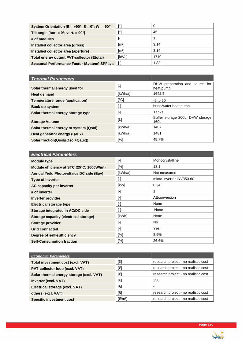
Page 120
System Orientation [E = +90°; S = 0°; W = -90°] [°] 0
Tilt angle [hor. = 0°; vert. = 90°] [°] 45
# of modules [-] 1
Installed collector area (gross) [m²] 3.14
Installed collector area (aperture) [m²] 3.14
Total energy output PVT-collector (Etotal) [kWh] 1710
Seasonal Performance Factor (System) SPFsys [-] 1.83
Thermal Parameters
Solar thermal energy used for [-]
DHW preparation and source for heat pump
Heat demand [kWh/a] 1642.5
Temperature range (application) [°C] -5 to 50
Back-up system [-] brine/water heat pump
Solar thermal energy storage type [-] Tanks
Storage Volume [L]
Buffer storage 200L, DHW storage 160L
Solar thermal energy to system (Qsol) [kWh/a] 1407
Heat generator energy (Qaux) [kWh/a] 1481
Solar fraction(Qsol/(Qsol+Qaux)) [%] 48.7%
Electrical Parameters
Module type [-] Monocrystalline
Module efficiency at STC (25°C; 1000W/m²) [%] 18.1
Annual Yield Photovoltaics DC side (Epv) [kWh/a] Not measured
Type of inverter [-] micro-inverter INV350-60
AC capacity per inverter [kW] 0.24
# of inverter [-] 1
Inverter provider [-] AEconversion
Electrical storage type [-] None
Storage integrated in AC/DC side [-] None
Storage capacity (electrical storage) [kWh] None
Storage provider [-] No
Grid connected [-] Yes
Degree of self-sufficiency [%] 8.9%
Self-Consumption fraction [%] 26.6%
Economic Parameters
Total investment cost (excl. VAT) [€] research project - no realistic cost
PVT-collector loop (excl. VAT) [€] research project - no realistic cost
Solar thermal energy storage (excl. VAT) [€] research project - no realistic cost
Inverter (excl. VAT) [€] 250
Electrical storage (excl. VAT) [€] -
others (excl. VAT) [€] research project - no realistic cost
Specific investment cost [€/m²] research project - no realistic cost

Existing PVT systems and solutions
Page 121
Calculated solar thermal system life time [a] 20
Subsidy, € or % of total investment costs [€/%] -
Fuel replaced [-] Electricity
Cost for fuel replaced [€/MWhfuel] 306
Local feed-in tariff [€/MWhelectricity] 80/53
Sources
Author [-] Mark Dannemand
Company of Author [-] DTU civil engineering
E-mail [-] [email protected]
Phone [-] +4545251887
Homepage [-] http://www.solvarme.byg.dtu.dk/
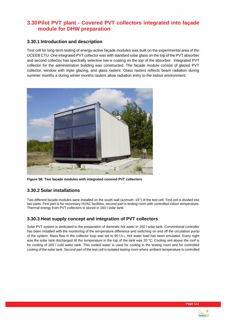
Page 122
3.30 Pilot PVT plant - Covered PVT collectors integrated into façade module for DHW preparation
3.30.1 Introduction and description
Test cell for long-term testing of energy-active façade modules was built on the experimental area of the
UCEEB CTU. One integrated PVT collector was with standard solar glass on the top of the PVT absorber
and second collector has spectrally selective low-e coating on the top of the absorber. Integrated PVT
collector for the administration building was constructed. The façade module consist of glazed PVT
collector, window with triple glazing, and glass rasters. Glass rasters reflects beam radiation during
summer months a during winter months rasters allow radiation entry to the indoor environment.
Figure 58: Two façade modules with integrated covered PVT collectors
3.30.2 Solar installations
Two different facade modules were installed on the south wall (azimuth -15°) of the test cell. Test cell is divided into two parts. First part is for necessary HVAC facilities, second part is testing room with controlled indoor temperature. Thermal energy from PVT collectors is stored in 160 l solar tank.
3.30.3 Heat supply concept and integration of PVT collectors
Solar PVT system is dedicated to the preparation of domestic hot water in 160 l solar tank. Conventional controller
has been installed with the monitoring of the temperature difference and switching on and off the circulation pump
of the system. Mass flow in the collector loop was set to 90 l.h-1. Hot water load has been emulated. Every night
was the solar tank discharged till the temperature in the top of the tank was 20 °C. Cooling unit above the roof is
for cooling of 200 l cold water tank. This cooled water is used for cooling in the testing room and for controlled
cooling of the solar tank. Second part of the test cell is isolated testing room where ambient temperature is controlled

Existing PVT systems and solutions
Page 123
by the electric heater and air cooler. Both cooling power and heating power are measured. PVT collectors are
connected with inverter and then the electrical energy is wasted in the grid.
Figure 59: Visualisation of the PVT system.
3.30.4 Fact sheet
General Information
Project name [-] Energy-active façade module
Country [-] Czech republic
City [-] Bustehrad
Year of operation start [mm/yyyy] 2017
PVT system owner(s) (%) [-] UCEEB CTU
PVT system operators(s) [-] UCEEB CTU
PVT system developer [-] UCEEB CTU
Application [-] DHW preparation
PLANT CONFIGURATION
Panel model [-] Prototype
PVT-Collector provider [-] UCEEB CTU
Category [-] PVT liquid collector
Type [-] covered
Working Fluid [-] Water/Glycol Mixture

Page 124
Kind of installation [-] façade integration
Tracking [-] No
System Orientation [E = +90°; S = 0°; W = -90°] [°] 15
Tilt angle [hor. = 0°; vert. = 90°] [°] 90
# of modules [-] 2
Installed collector area (gross) [m²] 3.12
Installed collector area (aperture) [m²] 2,8
Total energy output PVT-collector (Etotal) [kWh]
394 (1.2019-7.2019) One PVT collector (1,557 m2)
Seasonal Performance Factor (System) SPFsys [-] -
Thermal Parameters
Solar thermal energy used for [-] DHW preparation
Heat demand [kWh/a] -
Temperature range (application) [°C]
10 to 80 °C (stagnation temperature 160 °C)
Back-up system [-] -
Solar thermal energy storage type [-] Water – Short term
Storage Volume [L] Solar tank 160L
Solar thermal energy to system (Qsol) [kWh/a]
339 (1.2019-7.2019) One PVT collector (1,557 m2)
Heat generator energy (Qaux) [kWh/a] -
Solar fraction(Qsol/(Qsol+Qaux)) [%] -
Electrical Parameters
Module type [-] Monocrystalline
Module efficiency at STC (25°C; 1000W/m²) [%] 8,8
Annual Yield Photovoltaics DC side (Epv) [kWh/a]
55 (1.2019-7.2019) One PVT collector (1,557 m2)
Type of inverter [-] micro-inverter
AC capacity per inverter [kW] 0.24
# of inverter [-] 2
Inverter provider [-] GWL/POWER
Electrical storage type [-] -
Storage integrated in AC/DC side [-] -
Storage capacity (electrial storage) [kWh] -
Storage provider [-] -
Grid connected [-] Yes
Degree of self-sufficiency [%] -
Self-Consumption fraction [%] -
Economic Parameters
Total investment cost (excl. VAT) [€] -
PVT-collector loop (excl. VAT) [€] -
Solar thermal energy storage (excl. VAT) [€] -
Inverter (excl. VAT) [€] -
Electrical storage (excl. VAT) [€] -
Existing PVT systems and solutions
Page 125
others (excl. VAT) [€] -
Specific investment cost [€/m²] -
Calculated solar thermal system life time [a] -
Subsidy, € or % of total investment costs [€/%] -
Fuel replaced [-] -
Cost for fuel replaced [€/MWhfuel] -
Local feed-in tariff [€/MWhelectricity] -
Sources
Author [-] Nikola Pokorny
Company of Author [-] UCEEB CTU in Prague
E-mail [-] [email protected]
Phone [-] +420 777 048 835
Homepage [-] http://www.uceeb.cz


![Simplified SHC predesign tool - IEA SHC || Task 48 || IEA SHCtask48.iea-shc.org/Data/Sites/6/documents/events...Text °C 1 [-99.9 ; 99.9] Température extérieure moyenne horaire Ens_g_hz](https://static.fdocuments.us/doc/165x107/5f72d8148b9f220c6138886b/simplified-shc-predesign-tool-iea-shc-task-48-iea-text-c-1-999.jpg)