Exhibit 4 DETERMINATION OF STATIC PRESSURE … OF STATIC PRESSURE PERFORMANCE ... The Model 9968...
14
Executive Order VR-201-V and VR-202-V Assist Phase II EVR System Exhibit 4 DETERMINATION OF STATIC PRESSURE PERFORMANCE OF THE CLEAN AIR SEPARATOR 1 APPLICABILITY Definitions common to all certification and test procedures are in: D-200 Definitions for Vapor Recovery Procedures For the purpose of this procedure, the term “ARB” refers to the California Air Resources Board, and the term “Executive Officer” refers to the Executive Officer of the ARB or his or her authorized representative or designate. 1.1 This test procedure is used to quantify the vapor tightness of the Healy Clean Air Separator (CAS) pressure management system installed as part of a gasoline dispensing facility (GDF) under either Executive Order VR-201 or VR-202. 2 PRINCIPLE AND SUMMARY OF TEST PROCEDURE 2.1 The Clean Air Separator, while isolated from the vapor recovery system, is evaluated for vapor integrity using a vacuum decay procedure. The vacuum decay after 5 minutes is compared with an allowable value. The allowable value is based upon the initial vacuum level when conducting the test using the table provided in this test procedure. 2.2 A positive pressure decay procedure is included that conducts the same evaluation as the vacuum decay but with positive pressure. This test is conducted if there is insufficient vacuum (not greater than – 2.00” wc) to conduct the vacuum decay. Districts have the authority to specify in the permit conditions that this positive pressure test is to be conducted even if the vacuum test has been conducted. 3 RANGE 3.1 The full-scale range of the electronic measuring device shall not exceed 0-20.00” wc with a minimum accuracy of not less than 0.25 percent of full-scale.
Transcript of Exhibit 4 DETERMINATION OF STATIC PRESSURE … OF STATIC PRESSURE PERFORMANCE ... The Model 9968...
Executive Order VR-201-V and VR-202-V Assist Phase II EVR System
Exhibit 4 DETERMINATION OF STATIC PRESSURE PERFORMANCE
OF THE CLEAN AIR SEPARATOR 1 APPLICABILITY
Definitions common to all certification and test procedures are in:
D-200 Definitions for Vapor Recovery Procedures
For the purpose of this procedure, the term “ARB” refers to the California Air Resources Board, and the term “Executive Officer” refers to the Executive Officer of the ARB or his or her authorized representative or designate.
1.1 This test procedure is used to quantify the vapor tightness of the Healy Clean Air
Separator (CAS) pressure management system installed as part of a gasoline dispensing facility (GDF) under either Executive Order VR-201 or VR-202.
2 PRINCIPLE AND SUMMARY OF TEST PROCEDURE
2.1 The Clean Air Separator, while isolated from the vapor recovery system, is
evaluated for vapor integrity using a vacuum decay procedure. The vacuum decay after 5 minutes is compared with an allowable value. The allowable value is based upon the initial vacuum level when conducting the test using the table provided in this test procedure.
2.2 A positive pressure decay procedure is included that conducts the same
evaluation as the vacuum decay but with positive pressure. This test is conducted if there is insufficient vacuum (not greater than – 2.00” wc) to conduct the vacuum decay. Districts have the authority to specify in the permit conditions that this positive pressure test is to be conducted even if the vacuum test has been conducted.
3 RANGE
3.1 The full-scale range of the electronic measuring device shall not exceed
0-20.00” wc with a minimum accuracy of not less than 0.25 percent of full-scale.
VR-201-V / VR-202-V -2 Exhibit 4
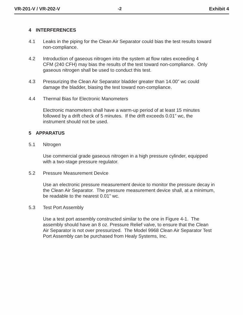
4 INTERFERENCES
4.1 Leaks in the piping for the Clean Air Separator could bias the test results toward
non-compliance.
4.2 Introduction of gaseous nitrogen into the system at flow rates exceeding 4 CFM (240 CFH) may bias the results of the test toward non-compliance. Only gaseous nitrogen shall be used to conduct this test.
4.3 Pressurizing the Clean Air Separator bladder greater than 14.00” wc could
damage the bladder, biasing the test toward non-compliance.
4.4 Thermal Bias for Electronic Manometers
Electronic manometers shall have a warm-up period of at least 15 minutes followed by a drift check of 5 minutes. If the drift exceeds 0.01” wc, the instrument should not be used.
5 APPARATUS
5.1 Nitrogen
Use commercial grade gaseous nitrogen in a high pressure cylinder, equipped with a two-stage pressure regulator.
5.2 Pressure Measurement Device
Use an electronic pressure measurement device to monitor the pressure decay in the Clean Air Separator. The pressure measurement device shall, at a minimum, be readable to the nearest 0.01” wc.
5.3 Test Port Assembly
Use a test port assembly constructed similar to the one in Figure 4-1. The assembly should have an 8 oz. Pressure Relief valve, to ensure that the Clean Air Separator is not over pressurized. The Model 9968 Clean Air Separator Test Port Assembly can be purchased from Healy Systems, Inc.

VR-201-V / VR-202-V -3 Exhibit 4
5.4 Stopwatch
FIGURE 4-1 Clean Air Separator Test Port Assembly
Use a stopwatch accurate to within 0.2 seconds.
5.5 Flow Meter
Use a flow meter to determine the required pressure setting of the delivery pressure gauge on the nitrogen supply pressure regulator. This pressure shall be set such that the nitrogen flow rate is between 2.0 CFM (120 CFH) and 4.0 CFM (240 CFH).
5.6 Leak Detection Solution
Any liquid solution designed to detect vapor leaks may be used to verify the pressure integrity of the test equipment prior to conducting the test.
5.7 Condensate Collection Vessel
A container approved for use with gasoline that can hold at least a half gallon of material.
5.8 Graduated Cylinder
A graduated cylinder suitable for use with gasoline capable of measuring to the nearest ounce or mL.

VR-201-V / VR-202-V -4 Exhibit 4
6 PRE-TEST PROCEDURES
6.1 The following safety precautions shall be followed:
6.1.1 Only gaseous nitrogen shall be used to pressurize the system.
6.1.2 An 8 oz. pressure relieve valve shall be installed on the Test Port Assembly to
prevent the possible over-pressurizing of the Clean Air Separator.
6.1.3 A ground strap should be employed during the introduction of nitrogen into the system.
6.2 There shall be no Phase I bulk product deliveries into or out of the gasoline
storage tank(s) within the three (3) hours prior to the test or during the performance of this test procedure.
6.3 All pressure measuring device(s) shall be bench calibrated using a reference
standard. Calibration shall be performed at 20, 50, and 80 percent of full scale. Accuracy shall be within two percent at each of these calibration points. Calibrations shall be conducted on a frequency not to exceed 180 days. Calibration documentation shall be maintained with the equipment at all times.
6.4 Use the flow meter to determine the nitrogen regulator delivery pressures that
correspond to nitrogen flow rates of 2.0 CFM (120 CFH) and 4.0 CFM (240 CFH). These pressures define the allowable range of delivery pressures acceptable for this test procedure. The flow meter shall be connected in-line between the nitrogen supply regulator and the Test Port Assembly during pressurization. The flow meter may be connected in-line between the nitrogen supply regulator and the Test Port Assembly during the test.
6.5 The electronic pressure measurement device shall be subject to warm-up and
drift check before use; see Section 4.5.
6.6 The four ball valves used in the installation of the Clean Air Separator are lockable and shall be locked in the position shown in Figure 2-2 or Figure 2-2H of Exhibit 2 and in Figure 4-1 or Figure 4-1H of this Exhibit during normal operation. Figure 4-1 and Figure 4-2 apply to vertical Clean Air Separator installations and Figure 4-1H and Figure 4-2H apply to horizontal Clean Air Separator installations. The four padlocks provided by Healy Systems, Inc. in their installation kit are keyed the same. However, it is possible that one or more of the padlocks on the Clean Air Separator could have been replaced (seizing, damage, broken key, etc.). Conducting this test will require a set of keys necessary to unlock all padlocks.

VR-201-V / VR-202-V -5 Exhibit 4
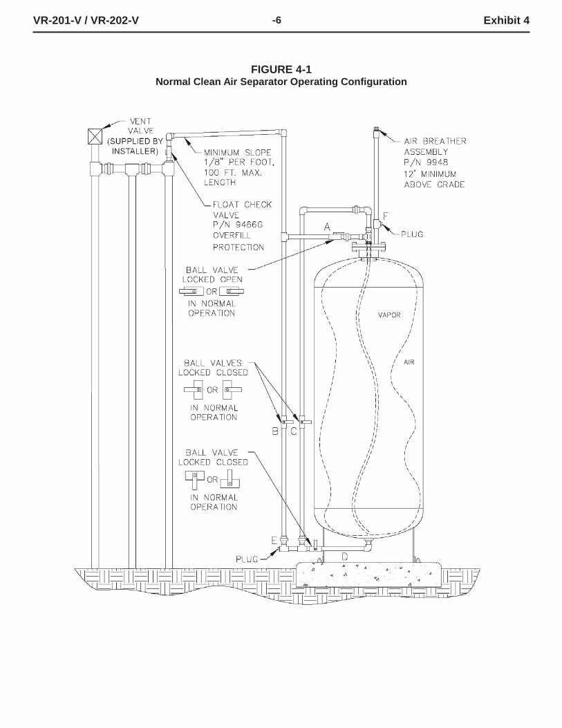
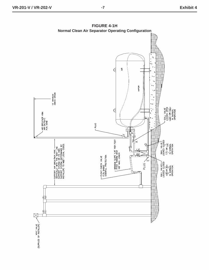
6.7 Verify that the Clean Air Separator is in its normal operating configuration by confirming that all components are as indicated (See Figure 4-1 or Figure 4-1H):
Valve “A” - Open Valve “B, C and D” - Closed Pipe End “E” - Plugged Tee Branch “F” - Plugged
VR-201-V / VR-202-V -6 Exhibit 4
FIGURE 4-1 Normal Clean Air Separator Operating Configuration
VR-201-V / VR-202-V -7 Exhibit 4
FIGURE 4-1H Normal Clean Air Separator Operating Configuration
VR-201-V / VR-202-V -8 Exhibit 4
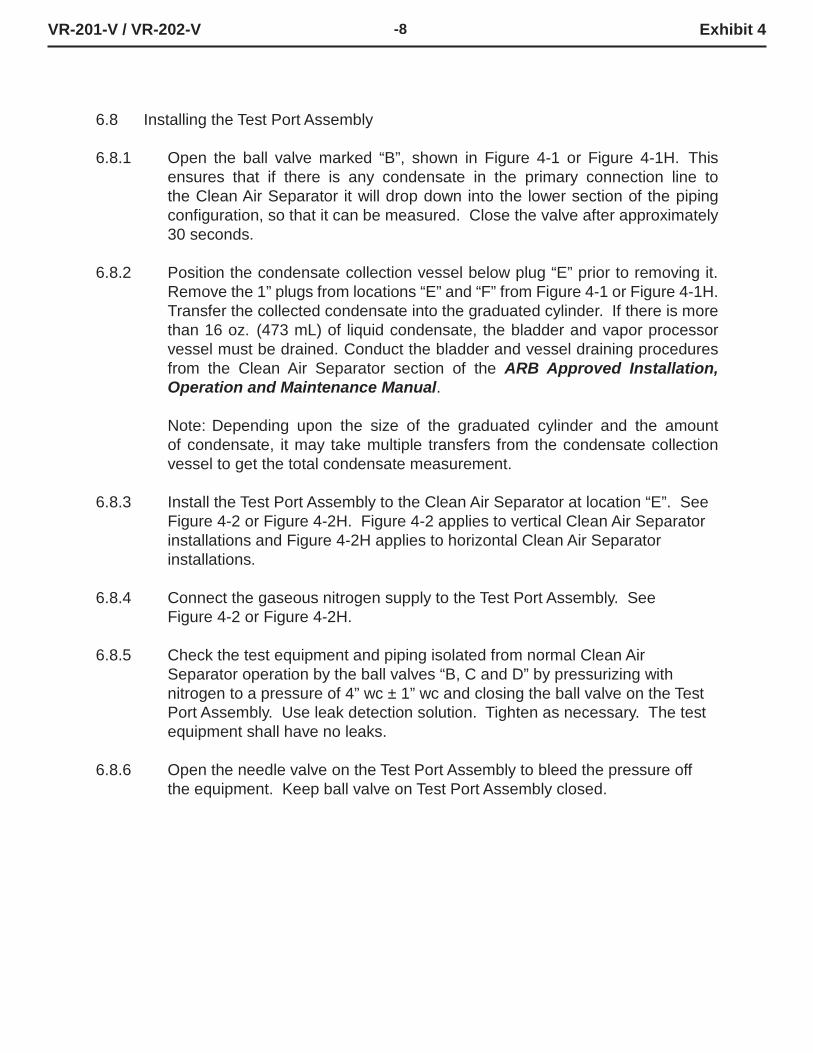
6.8 Installing the Test Port Assembly
6.8.1 Open the ball valve marked “B”, shown in Figure 4-1 or Figure 4-1H. This
ensures that if there is any condensate in the primary connection line to the Clean Air Separator it will drop down into the lower section of the piping configuration, so that it can be measured. Close the valve after approximately 30 seconds.
6.8.2 Position the condensate collection vessel below plug “E” prior to removing it.
Remove the 1” plugs from locations “E” and “F” from Figure 4-1 or Figure 4-1H. Transfer the collected condensate into the graduated cylinder. If there is more than 16 oz. (473 mL) of liquid condensate, the bladder and vapor processor vessel must be drained. Conduct the bladder and vessel draining procedures from the Clean Air Separator section of the ARB Approved Installation, Operation and Maintenance Manual.
Note: Depending upon the size of the graduated cylinder and the amount of condensate, it may take multiple transfers from the condensate collection vessel to get the total condensate measurement.
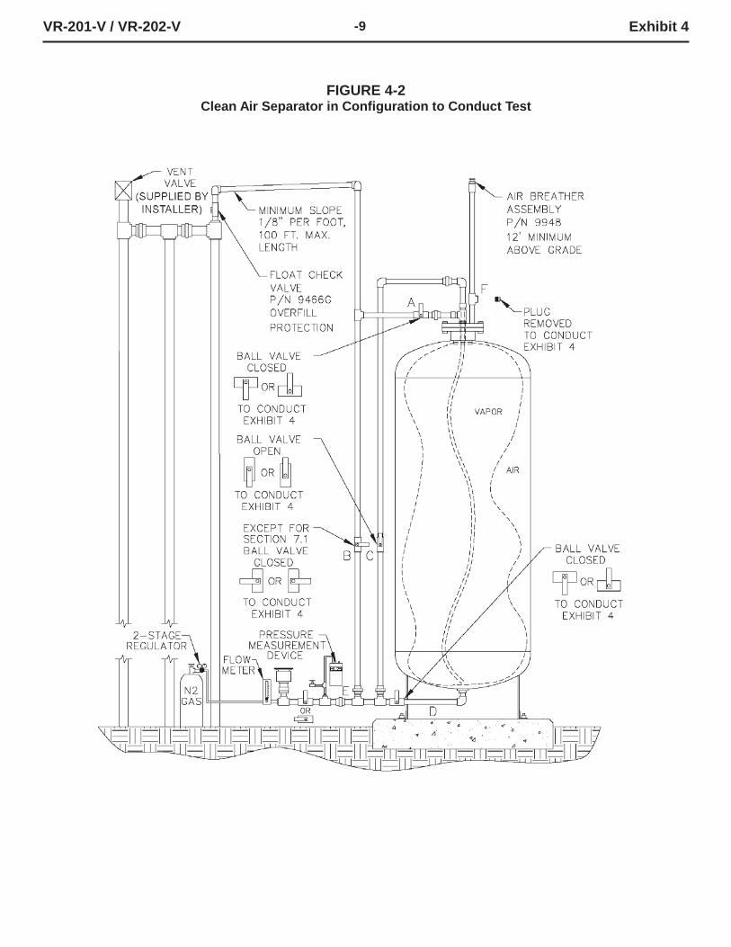
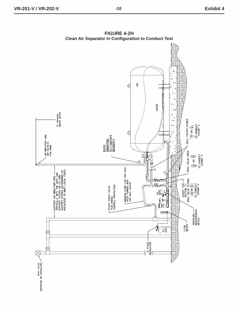
6.8.3 Install the Test Port Assembly to the Clean Air Separator at location “E”. See
Figure 4-2 or Figure 4-2H. Figure 4-2 applies to vertical Clean Air Separator installations and Figure 4-2H applies to horizontal Clean Air Separator installations.
6.8.4 Connect the gaseous nitrogen supply to the Test Port Assembly. See
Figure 4-2 or Figure 4-2H.
6.8.5 Check the test equipment and piping isolated from normal Clean Air Separator operation by the ball valves “B, C and D” by pressurizing with nitrogen to a pressure of 4” wc ± 1” wc and closing the ball valve on the Test Port Assembly. Use leak detection solution. Tighten as necessary. The test equipment shall have no leaks.
6.8.6 Open the needle valve on the Test Port Assembly to bleed the pressure off
the equipment. Keep ball valve on Test Port Assembly closed.
VR-201-V / VR-202-V -9 Exhibit 4
FIGURE 4-2 Clean Air Separator in Configuration to Conduct Test
VR-201-V / VR-202-V -10 Exhibit 4
FIGURE 4-2H Clean Air Separator in Configuration to Conduct Test
VR-201-V / VR-202-V -11 Exhibit 4
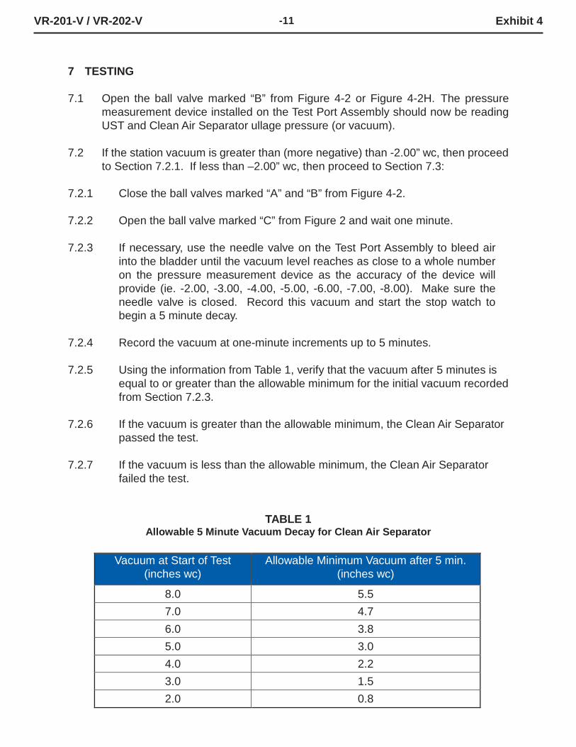
7 TESTING
7.1 Open the ball valve marked “B” from Figure 4-2 or Figure 4-2H. The pressure
measurement device installed on the Test Port Assembly should now be reading UST and Clean Air Separator ullage pressure (or vacuum).
7.2 If the station vacuum is greater than (more negative) than -2.00” wc, then proceed
to Section 7.2.1. If less than –2.00” wc, then proceed to Section 7.3:
7.2.1 Close the ball valves marked “A” and “B” from Figure 4-2.
7.2.2 Open the ball valve marked “C” from Figure 2 and wait one minute.
7.2.3 If necessary, use the needle valve on the Test Port Assembly to bleed air
into the bladder until the vacuum level reaches as close to a whole number on the pressure measurement device as the accuracy of the device will provide (ie. -2.00, -3.00, -4.00, -5.00, -6.00, -7.00, -8.00). Make sure the needle valve is closed. Record this vacuum and start the stop watch to begin a 5 minute decay.
7.2.4 Record the vacuum at one-minute increments up to 5 minutes.
7.2.5 Using the information from Table 1, verify that the vacuum after 5 minutes is
equal to or greater than the allowable minimum for the initial vacuum recorded from Section 7.2.3.
7.2.6 If the vacuum is greater than the allowable minimum, the Clean Air Separator
passed the test.
7.2.7 If the vacuum is less than the allowable minimum, the Clean Air Separator failed the test.
TABLE 1 Allowable 5 Minute Vacuum Decay for Clean Air Separator
Vacuum at Start of Test (inches wc)
Allowable Minimum Vacuum after 5 min. (inches wc)
8.0 5.5 7.0 4.7 6.0 3.8 5.0 3.0 4.0 2.2 3.0 1.5 2.0 0.8
VR-201-V / VR-202-V -12 Exhibit 4
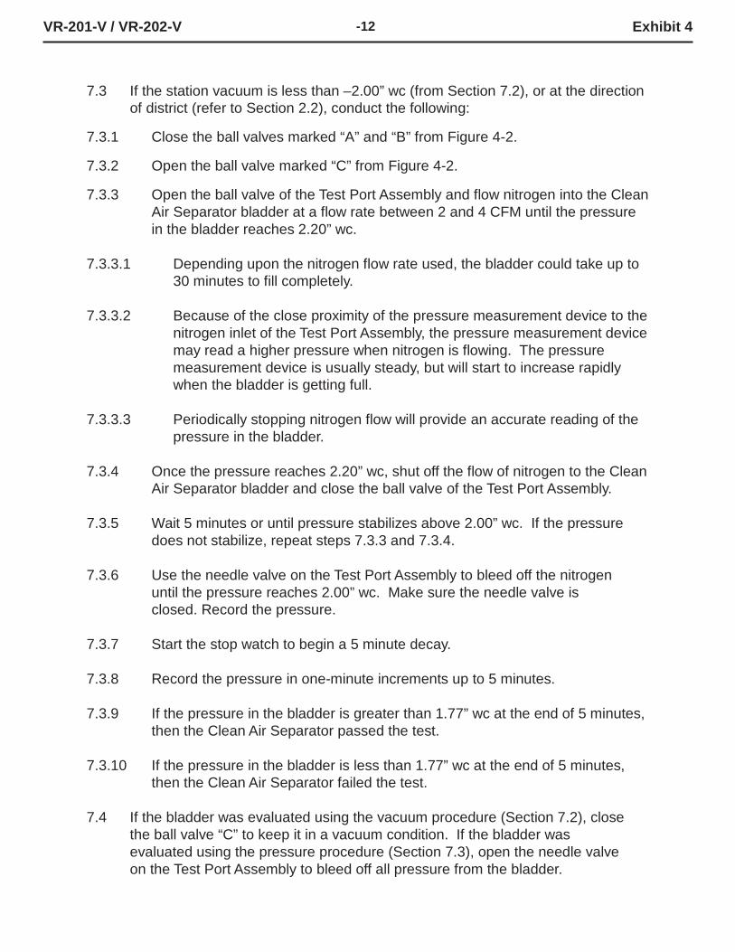
7.3 If the station vacuum is less than –2.00” wc (from Section 7.2), or at the direction of district (refer to Section 2.2), conduct the following:
7.3.1 Close the ball valves marked “A” and “B” from Figure 4-2.
7.3.2 Open the ball valve marked “C” from Figure 4-2.
7.3.3 Open the ball valve of the Test Port Assembly and flow nitrogen into the Clean
Air Separator bladder at a flow rate between 2 and 4 CFM until the pressure in the bladder reaches 2.20” wc.
7.3.3.1 Depending upon the nitrogen flow rate used, the bladder could take up to
30 minutes to fill completely.
7.3.3.2 Because of the close proximity of the pressure measurement device to the nitrogen inlet of the Test Port Assembly, the pressure measurement device may read a higher pressure when nitrogen is flowing. The pressure measurement device is usually steady, but will start to increase rapidly when the bladder is getting full.
7.3.3.3 Periodically stopping nitrogen flow will provide an accurate reading of the
pressure in the bladder.
7.3.4 Once the pressure reaches 2.20” wc, shut off the flow of nitrogen to the Clean Air Separator bladder and close the ball valve of the Test Port Assembly.
7.3.5 Wait 5 minutes or until pressure stabilizes above 2.00” wc. If the pressure
does not stabilize, repeat steps 7.3.3 and 7.3.4.
7.3.6 Use the needle valve on the Test Port Assembly to bleed off the nitrogen until the pressure reaches 2.00” wc. Make sure the needle valve is closed. Record the pressure.
7.3.7 Start the stop watch to begin a 5 minute decay.
7.3.8 Record the pressure in one-minute increments up to 5 minutes.
7.3.9 If the pressure in the bladder is greater than 1.77” wc at the end of 5 minutes,
then the Clean Air Separator passed the test.
7.3.10 If the pressure in the bladder is less than 1.77” wc at the end of 5 minutes, then the Clean Air Separator failed the test.
7.4 If the bladder was evaluated using the vacuum procedure (Section 7.2), close
the ball valve “C” to keep it in a vacuum condition. If the bladder was evaluated using the pressure procedure (Section 7.3), open the needle valve on the Test Port Assembly to bleed off all pressure from the bladder.
VR-201-V / VR-202-V -13 Exhibit 4
7.5 Close the ball valve marked “C”, if not already done.
7.6 Remove the Test Port Assembly from location “E” and install the 1” pipe plug.
Use a pipe sealant approved for use with gasoline on the threads and tighten to 60 ft-lbs.
7.7 Install the 1” pipe plug to location “F”. Use a pipe sealant approved for use with
gasoline on the threads and tighten to 60 ft-lbs.
7.8 Open the ball valve marked “A”. Lock all ball valves using the padlocks.
7.9 The Clean Air Separator should now be in normal operation configuration. Verify
this by using the outline from Section 6.7 and Figure 4-1 or Figure 4-1H.
8 REPORTING
8.1 Record test data on the form shown in Figure 4-3. Districts may require the use
of an alternate form, provided that the alternate form includes the same minimum parameters as in Figure 4-3.

VR-201-V / VR-202-V -14 Exhibit 4
FIGURE 4-3
Data Form for Determination of Static Pressure Performance of the Healy Clean Air Separator for Executive Orders VR-201 and VR-202
SOURCE INFORMATION
GDF Name and address: GDF Representative and title:
GDF Phone No.
Date and Time of Last Fuel Drop to GDF:
P/O #:
A/C#:
Date of Last Calibration of Pressure Measurement Device:
District Test Witness:
VACUUM TEST (Section 7.1 through 7.2.7)
Vacuum at start of test, inches water column (7.2.3) Vacuum at one minute, inches water column Vacuum at two minutes, inches water column Vacuum at three minutes, inches water column Vacuum at four minutes, inches water column Final vacuum at five minutes, inches water column Allowable minimum vacuum, inches water column (from Table 1)
POSITIVE PRESSURE TEST (Section 7.3 through 7.3.9)
Pressure at start of test, inches water column (7.3.6) Pressure at one minute, inches water column Pressure at two minutes, inches water column Pressure at three minutes, inches water column Pressure at four minutes, inches water column Final pressure at five minutes, inches water column Allowable final pressure, inches water column (7.3.9) 1.77
Certified Technician Name Test Company Date Test Conducted
Certification Number:
Expiration Date: