Exhaust System Manifolds and Elbows with Dry...
14
Manifolds and Elbows with Dry Joint 90-864260400 AUGUST 2009 Page 7C-1 7 C Exhaust System Section 7C - Manifolds and Elbows with Dry Joint Table of Contents Models Covered.................................................................7C-2 Dry Joint Models.........................................................7C-2 Warm Manifolds.................................................................7C-3 Exploded View............................................................7C-3 Removal.....................................................................7C-3 Cleaning and Inspection.............................................7C-4 Assembly....................................................................7C-4 Gasket Application.............................................................7C-5 Restrictor Gasket........................................................7C-5 Block‑Off Gasket........................................................7C-6 Installation..................................................................7C-6
Transcript of Exhaust System Manifolds and Elbows with Dry...

Manifolds and Elbows with Dry Joint
90-864260400 AUGUST 2009 Page 7C-1
7C
Exhaust SystemSection 7C - Manifolds and Elbows with Dry Joint
Table of Contents
Models Covered.................................................................7C-2Dry Joint Models.........................................................7C-2
Warm Manifolds.................................................................7C-3Exploded View............................................................7C-3Removal.....................................................................7C-3Cleaning and Inspection.............................................7C-4
Assembly....................................................................7C-4Gasket Application.............................................................7C-5
Restrictor Gasket........................................................7C-5Block‑Off Gasket........................................................7C-6Installation..................................................................7C-6
Manifolds and Elbows with Dry Joint
Page 7C-2 90-864260400 AUGUST 2009
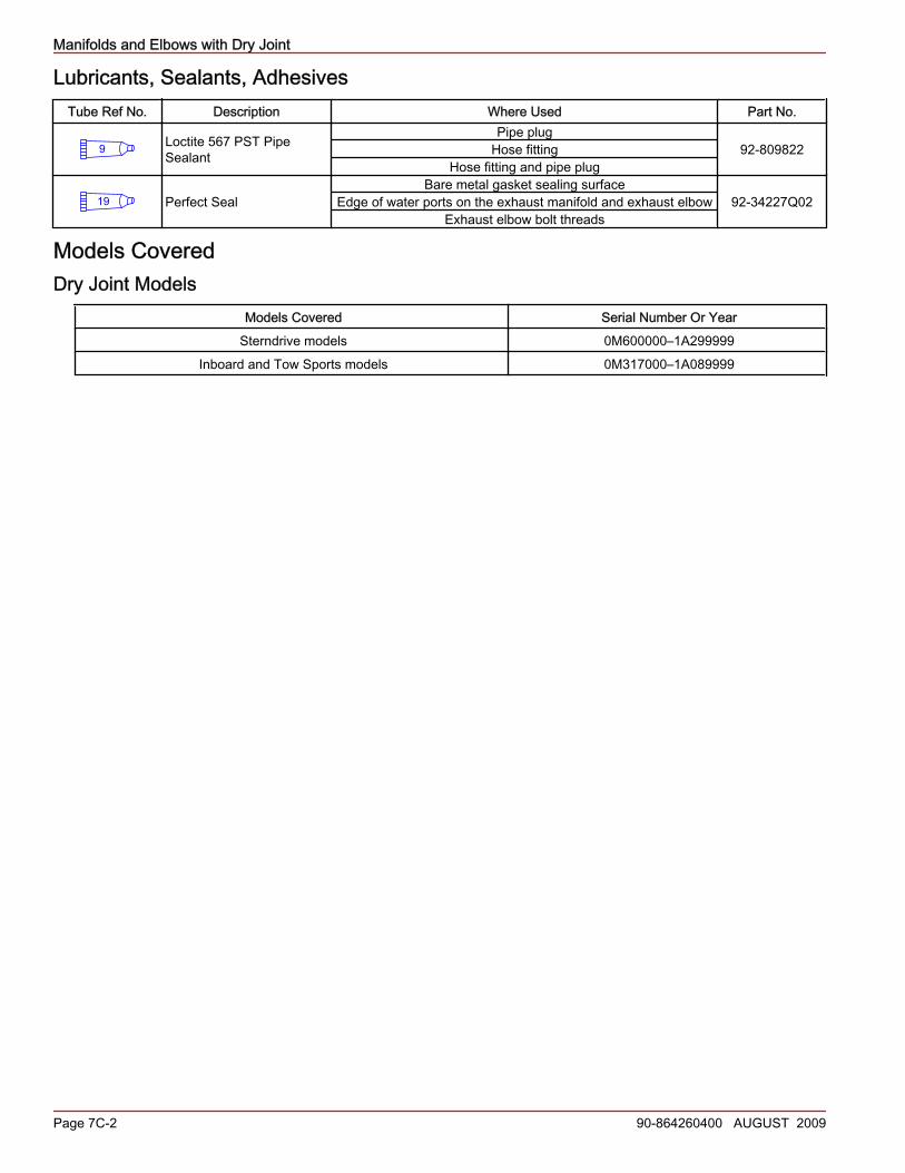
Lubricants, Sealants, AdhesivesTube Ref No. Description Where Used Part No.
9 Loctite 567 PST PipeSealant
Pipe plugHose fitting
Hose fitting and pipe plug92-809822
19 Perfect SealBare metal gasket sealing surface
Edge of water ports on the exhaust manifold and exhaust elbowExhaust elbow bolt threads
92-34227Q02
Models CoveredDry Joint Models
Models Covered Serial Number Or YearSterndrive models 0M600000–1A299999
Inboard and Tow Sports models 0M317000–1A089999

Manifolds and Elbows with Dry Joint
90-864260400 AUGUST 2009 Page 7C-3
Warm ManifoldsExploded View
NOTE: 7° elbows shown, 14° elbow similar
Seawater cooled assembly Closed cooled assemblya - Exhaust manifoldb - Manifold to cylinder head boltc - Restrictor gasket with turbulator (seawater cooled models)d - Exhaust elbowe - Pipe plugf - Hose fittingg - Block‑off gasket with turbulator (closed cooled models)h - Exhaust elbow to exhaust manifold bolti - Flat washer used with early 14° elbow
NOTE: Replacement fasteners "b" will be flange head bolts.NOTE: Replacement fasteners "h" will be flange head bolts.
Removal
! WARNINGPerforming service or maintenance without first disconnecting the battery can cause product damage, personal injury, or deathdue to fire, explosion, electrical shock, or unexpected engine starting. Always disconnect the battery cables from the batterybefore maintaining, servicing, installing, or removing engine or drive components.
1. Disconnect both battery cables from the battery.2. Seawater Cooled Models: Drain the seawater section of the engine.3. Closed Cooled Models: Drain the coolant section of the engine. Refer to Section 6C.4. Disconnect the engine exhaust hoses. Retain the fasteners.
e
fg
a
b
d
c
h
i
31173

Manifolds and Elbows with Dry Joint
Page 7C-4 90-864260400 AUGUST 2009
5. Disconnect all hoses from the exhaust manifold and exhaust elbow. Retain the fasteners.6. Remove and retain any items or components that are mounted to the manifold and the exhaust elbow of the engine.7. Remove the exhaust elbow. Retain the fasteners.
NOTE: Some engines were built with hex head bolts and washers.8. Remove the exhaust manifold. Retain the fasteners.9. Discard the used gaskets.
Cleaning and Inspection1. Clean the gasket material from all surfaces and wash the parts in solvent.2. Inspect the water passages for foreign material. The passages must be clean for efficient cooling.
NOTE: If more thorough inspection is desired, the pipe plugs may be removed from the exhaust manifold and the exhaustelbow.IMPORTANT: If the pipe plugs are removed, coat the threads with sealant before reinstalling.
Tube Ref No. Description Where Used Part No.
9 Loctite 567 PST PipeSealant Pipe plug 92-809822
3. Inspect the manifold, elbow, and riser for cracks.4. Inspect all parts carefully. Machined surfaces must be clean and free of all marks and deep scratches or leaks may result.5. Inspect for damaged metal caused by saltwater or exhaust gas corrosion in the manifold, elbow, and riser.6. Measure the surface flatness of all gasket surfaces on the exhaust manifold, elbow, and riser.
a - Gasket sealing surfaceb - Top‑view of manifoldc - Bottom‑view of elbow
NOTE: Only use this specification if the gasket surfaces on used exhaust components have to be machined to remove minorcorrosion.
Description mm (in.)Surface flatness Maximum overall difference 0.07 (0.003)
NOTE: The maximum material that can be removed is 0.25 mm (0.010 in.). When tightening the attaching bolts, ensure thatthey are not contacting the bottom of the threaded hole in the manifold.NOTE: Gasket is not reusable. Inspect for proper gasket replacement before disassembly and assembly.
7. Replace all damaged components.
AssemblyIMPORTANT: The edge of the water ports on all cast iron parts must be coated with Perfect Seal during assembly.IMPORTANT: If bare metal is present on the gasket sealing surface, Perfect Seal should be applied to that area before assembly.
Tube Ref No. Description Where Used Part No.
19 Perfect Seal Bare metal gasket sealing surface 92-34227Q02
b c
a
31775

Manifolds and Elbows with Dry Joint
90-864260400 AUGUST 2009 Page 7C-5
1. If exhaust elbow assembly is disassembled or risers are added, apply sealant to edge of all water ports (exhaust manifold,both sides of the riser, and exhaust elbow).
a - Water portsb - Exhaust manifoldc - Exhaust elbow
a - Exhaust manifold (crosssection)
b - Exhaust manifold waterport
c - Edge of water port (areato apply sealant)
Tube Ref No. Description Where Used Part No.
19 Perfect Seal Edge of water ports on the exhaust manifold and exhaust elbow 92-34227Q02
Gasket ApplicationRestrictor Gasket
Models Covered DescriptionSeawater cooled Restrictor gasket
IMPORTANT: On engines without risers, the restrictor gasket must be placed between the exhaust manifold and the exhaustelbow.
a
b
c
31776
31777
ab
c

Manifolds and Elbows with Dry Joint
Page 7C-6 90-864260400 AUGUST 2009
IMPORTANT: The restrictor end of the gasket must be positioned to the seawater inlet side of the exhaust elbow.
a - Full flow passageb - Restricted flow passagec - Turbulator oriented up
Block‑Off GasketModels Covered DescriptionClosed cooled Block‑off gasket
IMPORTANT: On engines without risers, the block‑off gasket must be placed between the exhaust manifold and the exhaustelbow.
a - No opening for coolant flowb - Turbulator oriented up
InstallationIMPORTANT: The correct turbulator gasket must be properly installed to avoid overheating due to insufficient water flow or coolantloss through exhaust.IMPORTANT: See Section 7D—Cold Riser Models With Dry Joint and Section 7E—Warm Riser Models With Dry Joint if exhaustrisers are used.
a
b
c31778
b
a
31779

Manifolds and Elbows with Dry Joint
90-864260400 AUGUST 2009 Page 7C-7
1. Seawater Cooled Models: Apply sealant to threads of pipe plug and install to exhaust manifold.
a - Exhaust manifoldb - Pipe plugc - Sealant applied to threads
Tube Ref No. Description Where Used Part No.
9 Loctite 567 PST PipeSealant Pipe plug 92-809822
2. Tighten the pipe plug.
Description Nm lb‑in. lb‑ftExhaust manifold and exhaust elbow pipe plug 50 – 37
3. Closed Cooled Models: Apply sealant to threads of hose fitting and install to exhaust manifold.
a - Exhaust manifoldb - Hose fittingc - Sealant applied to threads
Tube Ref No. Description Where Used Part No.
9 Loctite 567 PST PipeSealant Hose fitting 92-809822
4. Tighten the hose fitting.
Description Nm lb‑in. lb‑ftExhaust manifold and exhaust elbow pipe plug 50 – 37
5. Using new exhaust manifold gasket, install exhaust manifold to cylinder head. Tighten the fasteners.
Description Nm lb‑in. lb‑ftExhaust manifold to cylinder head bolt 43 – 32
a
cb
31780
a
b
c
31781
Manifolds and Elbows with Dry Joint
Page 7C-8 90-864260400 AUGUST 2009
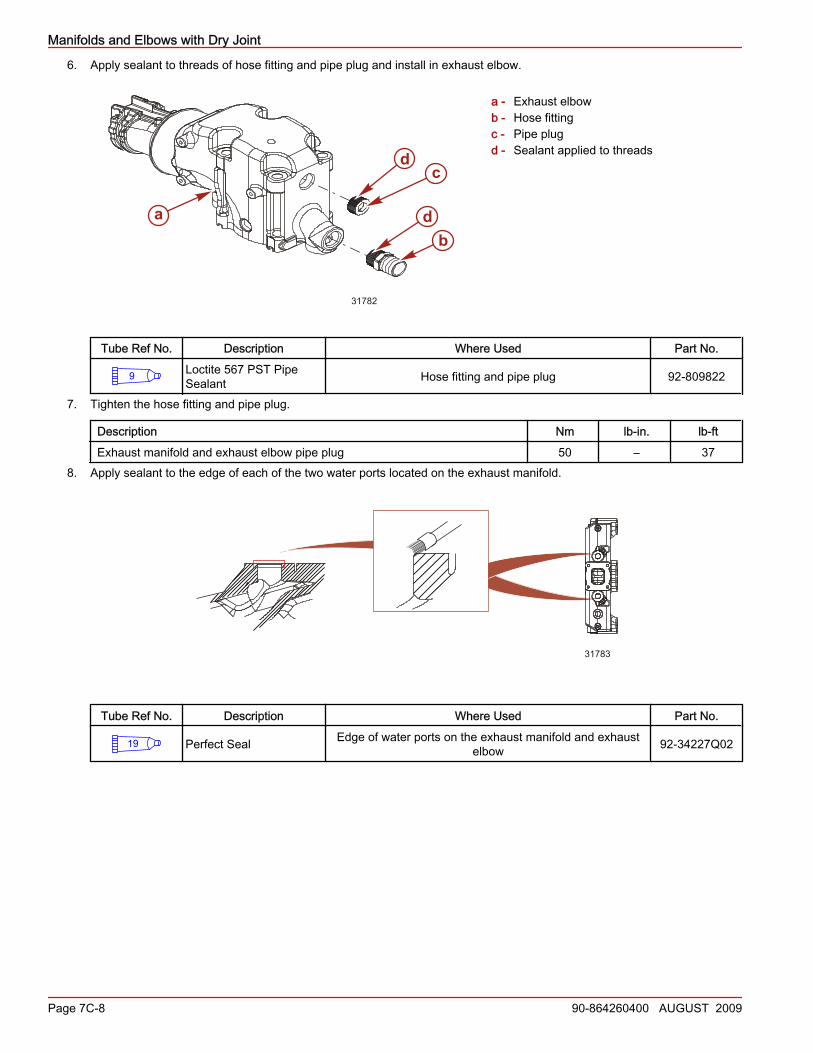
6. Apply sealant to threads of hose fitting and pipe plug and install in exhaust elbow.
a - Exhaust elbowb - Hose fittingc - Pipe plugd - Sealant applied to threads
Tube Ref No. Description Where Used Part No.
9 Loctite 567 PST PipeSealant Hose fitting and pipe plug 92-809822
7. Tighten the hose fitting and pipe plug.
Description Nm lb‑in. lb‑ftExhaust manifold and exhaust elbow pipe plug 50 – 37
8. Apply sealant to the edge of each of the two water ports located on the exhaust manifold.
31783
Tube Ref No. Description Where Used Part No.
19 Perfect Seal Edge of water ports on the exhaust manifold and exhaustelbow 92-34227Q02
dc
bda
31782

Manifolds and Elbows with Dry Joint
90-864260400 AUGUST 2009 Page 7C-9
9. Seawater Cooled Models: Place the restrictor gasket on the exhaust manifold with the side marked "UP" visible. Ensure therestricted water port of restrictor gasket is on the same side as the hose fitting of the exhaust elbow.
Sterndrive, Inboard andTow Sports in-line exhaustseawater cooled model
a - Restrictor gasketpositioned betweenexhaust manifold andexhaust elbow
b - Restricted water port ofgasket is in line withhose fitting of exhaustelbow
c - Exhaust elbow inletwater port with hosefitting
d - Exhaust manifold outletwater port with pipe plug
Inboard V-drive seawater cooledmodel
a - Restrictor gasket positionedbetween exhaust manifold andexhaust elbow
b - Restricted water port of gasket is inline with hose fitting of exhaustelbow
c - Exhaust elbow inlet water port withhose fitting
d - Exhaust manifold outlet water portwith pipe plug
a
b
cd
31784
a
b
d31785
c

Manifolds and Elbows with Dry Joint
Page 7C-10 90-864260400 AUGUST 2009
10. Closed Cooled Models: Place the block‑off gasket on the exhaust manifold with the side marked "UP" visible.
Sterndrive, Inboard in-line exhaust closed cooled modela - Block‑off gasket positioned between exhaust manifold and exhaust elbowb - Exhaust elbow inlet water port with hose fittingc - Exhaust manifold outlet coolant port with hose fitting
11. Apply sealant to the edge of each of the two water ports located on the exhaust elbow.
31787
Tube Ref No. Description Where Used Part No.
19 Perfect Seal Edge of water ports on the exhaust manifold and exhaustelbow 92-34227Q02
a
bc
31786
Manifolds and Elbows with Dry Joint
90-864260400 AUGUST 2009 Page 7C-11
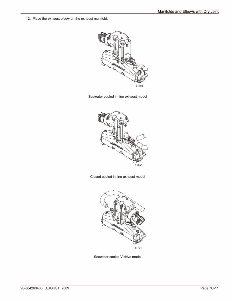
12. Place the exhaust elbow on the exhaust manifold.
31788
Seawater cooled in-line exhaust model
31790
Closed cooled in-line exhaust model
31791
Seawater cooled V-drive model

Manifolds and Elbows with Dry Joint
Page 7C-12 90-864260400 AUGUST 2009
31792
Closed cooled V-drive model
IMPORTANT: To ensure correct torque, the exhaust elbow screws without a flanged head require that a specific flat washerbe used in conjunction with the screw. If a flange head bolt is used, no washer is needed. Refer to the Mercury PrecisionParts/Quicksilver Accessories Guide.
13. If applicable, assemble washers to the exhaust elbow bolts.14. Apply sealant to exhaust elbow bolt threads and hand‑start to temporarily secure the assembly.
Tube Ref No. Description Where Used Part No.
19 Perfect Seal Exhaust elbow bolt threads 92-34227Q02
15. Align the exhaust elbow to the engine exhaust system.NOTE: Gasket is not reusable. Inspect for proper gasket and component position before torquing.
16. Tighten the exhaust elbow fasteners.IMPORTANT: Tighten the fasteners evenly using X pattern from corner to corner
Description Nm lb‑in. lb‑ft
Exhaust elbow to exhaustmanifold bolt or nut
First pass 9 – 7Final pass 61 – 45
17. Seawater Cooled Models: Connect the engine water hoses to the exhaust elbows and tighten hose clamps securely.18. Closed Cooled Models: Connect the engine coolant hose from the thermostat housing to the hose fitting of the top of the
exhaust manifold. Tighten hose clamps securely.
a - Hose fitting of the exhaust manifoldb - Exhaust manifoldc - Engine coolant hose
a
b
c
31793
Manifolds and Elbows with Dry Joint
90-864260400 AUGUST 2009 Page 7C-13
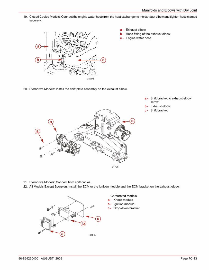
19. Closed Cooled Models: Connect the engine water hose from the heat exchanger to the exhaust elbow and tighten hose clampssecurely.
a - Exhaust elbowb - Hose fitting of the exhaust elbowc - Engine water hose
20. Sterndrive Models: Install the shift plate assembly on the exhaust elbow.
a - Shift bracket to exhaust elbowscrew
b - Exhaust elbowc - Shift bracket
21. Sterndrive Models: Connect both shift cables.22. All Models Except Scorpion: Install the ECM or the ignition module and the ECM bracket on the exhaust elbow.
Carbureted modelsa - Knock moduleb - Ignition modulec - Drop‑down bracket
a
b c
31794
a
b c
31795
a
bc
31549

Manifolds and Elbows with Dry Joint
Page 7C-14 90-864260400 AUGUST 2009
MPI modelsa - Exhaust elbowb - ECM bracketc - Short screwd - ECM
23. Secure the engine exhaust system.24. Install any additional components removed during disassembly.25. Closed Cooled Models: Fill closed cooling system to operating level. Refer to Section 6C.26. Reconnect the battery cables to the battery. Tighten securely.
NOTICEWithout sufficient cooling water, the engine, the water pump, and other components will overheat and suffer damage. Providea sufficient supply of water to the water inlets during operation.
27. Supply cooling water to the engine.28. Start the engine and check for exhaust and water leaks.
d
b
c
41932
a