EXERGY AND EXERGOECONOMIC ANALYSIS OF A STEAM...
12
Mitrović, D. M., et al.: Exergy and Exergoeconomic Analysis of a Steam Boiler THERMAL SCIENCE: Year 2018, Vol. 22, Suppl. 5, pp. S1601-S1612 S1601 EXERGY AND EXERGOECONOMIC ANALYSIS OF A STEAM BOILER by Dejan M. MITROVI] * , Branislav V. STOJANOVI], Jelena N. JANEVSKI, Marko G. IGNJATOVI], and Goran D. VU^KOVI] Faculty of Mechanical Engineering, University of Nis, Nis, Serbia Original scientific paper https://doi.org/10.2298/TSCI18S5601M Relying on coal as primary fuel in thermal power plants represents an unsustain- able concept due to limited coal reserves and a negative environmental impact. Efficient utilization of coal reserves and a request for minimization of irreversi- bilities are imperative for thermal power plants operation. Numerous studies have shown that a steam boiler is a thermal power plant component with the highest irreversibility. The idea of this paper is to quantify the amounts and sources of irreversibilities within a steam boiler and its components, serving a 348.5MWe thermal power plant. Having this in mind, exergy and exergoeconom- ic analysis of a steam boiler is presented in this paper. Exergy destruction and exergy efficiency of all boiler components and of the boiler as a whole were cal- culated. Based on exergy flows and economic parameters (cost of the boiler, an- nual operation hours of the unit, maintenance factor, interest rate, operating pe- riod of the boiler), exergy analysis resulted in the cost of produced steam. The obtained results show that the boiler exergy efficiency is at 47.4%, with the larg- est exergy destruction occurring in the combustion chamber with a value of 288.07 MW (60.04%), and the smallest in the air heater with a value of 4.57 MW (0.95%). The cost of produced steam is calculated at 49,356.7 $/h by applying exergoeconomic analysis. Key words: exergy destruction, efficiency, exergoeconomic analysis, steam boiler Introduction Traditional analysis and calculation methods for complex thermal plants are based on the First law of thermodynamics. These methods use system the energy balance approach. By using the energy balance approach, one can obtain the energy demand in the form of heat flows, energy and mechanical work, but without precise information on whether or not this energy is efficiently utilized in the system. Energy balance does not provide information on internal losses. The only inefficiencies detected by the energy balance approach are related to energy transfer outside the observed system. On the other hand, the Second law of thermody- namics introduces exergy, which is far more suitable for analysis of thermal plants. This com- plements and improves energy balance by allowing the determination of the thermodynamic value of the energy carrier and real thermodynamic inefficiencies in processes or systems. Real thermodynamic inefficiencies of the system are exergy destruction within the system boundaries and exergy losses (exergy transfer outside the system boundaries). –––––––––––––– * Corresponding author, e-mail: [email protected]
Transcript of EXERGY AND EXERGOECONOMIC ANALYSIS OF A STEAM...
Mitrović, D. M., et al.: Exergy and Exergoeconomic Analysis of a Steam Boiler THERMAL SCIENCE: Year 2018, Vol. 22, Suppl. 5, pp. S1601-S1612 S1601
EXERGY AND EXERGOECONOMIC ANALYSIS
OF A STEAM BOILER
by
Dejan M. MITROVI]*
, Branislav V. STOJANOVI], Jelena N. JANEVSKI,
Marko G. IGNJATOVI], and Goran D. VU^KOVI]
Faculty of Mechanical Engineering, University of Nis, Nis, Serbia Original scientific paper
https://doi.org/10.2298/TSCI18S5601M
Relying on coal as primary fuel in thermal power plants represents an unsustain-able concept due to limited coal reserves and a negative environmental impact. Efficient utilization of coal reserves and a request for minimization of irreversi-bilities are imperative for thermal power plants operation. Numerous studies have shown that a steam boiler is a thermal power plant component with the highest irreversibility. The idea of this paper is to quantify the amounts and sources of irreversibilities within a steam boiler and its components, serving a 348.5MWe thermal power plant. Having this in mind, exergy and exergoeconom-ic analysis of a steam boiler is presented in this paper. Exergy destruction and exergy efficiency of all boiler components and of the boiler as a whole were cal-culated. Based on exergy flows and economic parameters (cost of the boiler, an-nual operation hours of the unit, maintenance factor, interest rate, operating pe-riod of the boiler), exergy analysis resulted in the cost of produced steam. The obtained results show that the boiler exergy efficiency is at 47.4%, with the larg-est exergy destruction occurring in the combustion chamber with a value of 288.07 MW (60.04%), and the smallest in the air heater with a value of 4.57 MW (0.95%). The cost of produced steam is calculated at 49,356.7 $/h by applying exergoeconomic analysis.
Key words: exergy destruction, efficiency, exergoeconomic analysis, steam boiler
Introduction
Traditional analysis and calculation methods for complex thermal plants are based
on the First law of thermodynamics. These methods use system the energy balance approach.
By using the energy balance approach, one can obtain the energy demand in the form of heat
flows, energy and mechanical work, but without precise information on whether or not this
energy is efficiently utilized in the system. Energy balance does not provide information on
internal losses. The only inefficiencies detected by the energy balance approach are related to
energy transfer outside the observed system. On the other hand, the Second law of thermody-
namics introduces exergy, which is far more suitable for analysis of thermal plants. This com-
plements and improves energy balance by allowing the determination of the thermodynamic
value of the energy carrier and real thermodynamic inefficiencies in processes or systems.
Real thermodynamic inefficiencies of the system are exergy destruction within the system
boundaries and exergy losses (exergy transfer outside the system boundaries).
–––––––––––––– * Corresponding author, e-mail: [email protected]
Mitrović, D. M., et al.: Exergy and Exergoeconomic Analysis of a Steam Boiler S1602 THERMAL SCIENCE: Year 2018, Vol. 22, Suppl. 5, pp. S1601-S1612
Exergy is used for determining energy quality and enables finding the location,
cause and real values of generated losses as well as determining residues in a thermal process.
When two systems with different states interact, they tend to reach equilibrium, thus perform-
ing work. If one of the systems represents surroundings and the other the thermodynamic sys-
tem of interest, then the maximal possible work obtained by the interaction between these sys-
tems and reaching equilibrium is exergy, assuming only heat is being exchanged. Every sys-
tem not in equilibrium with its surroundings has the potential to perform work. Every system
which is in equilibrium with its surrounding, by definition, does not have the potential to per-
form work. Exergy can be treated as the distance of the state of a certain system from the state
of its surroundings. Exergy can be destroyed but cannot be conserved (preserved). Exergy is
completely destroyed if a system reaches equilibrium spontaneously with its surroundings
without performing work.
Exergy analysis is a method that combines heat and mass balance with the Second
law of thermodynamics. Exergy analysis enables determining the location, causes and sources
of losses. This information can be used for constructing new energy-efficient systems, but al-
so for improving the performance of the existing systems. Furthermore, exergy analysis pro-
vides an insight into and allows finding causes for thermodynamic inefficiency of systems.
In Serbia, 74% of electricity is produced in coal-fired thermal power plants with
steam turbines (Energy Balance of the Republic of Serbia in 2014). Since steam boilers are
used for transforming chemical energy of fuel into heat energy of water steam, significant
primary energy savings can be achieved by improving the efficiency of the steam boiler in
operation. For this reason it is very important to maximize heat transfer to water/steam and to
reduce heat losses in the boiler, by identifying and quantifying these losses.
Many authors have applied exergy analysis to steam boilers in industrial facilities or
thermal power plants. Talatappeh and Gazikhani [1] performed a boiler exergy analysis of an
experimental thermal power plant. In the research they divided the boiler into three regions
(combustion, heat transfer to water or steam, and exhaust) and calculated irreversibility in
every region. The results showed the maximum irreversibility of 54.8% in the second region,
39% in the first region, and 6% in the third region, for the maximum boiler pressure of 8 bar.
In their research, Gulhane and Thakur [2] analyzed a co-generation system in order to quanti-
fy and identify the sources of irreversibilities generated in the boiler. Exergy analysis revealed
that for the load of 1.1 MW, exergy destruction in the boiler was approximately 83.35% com-
pared to the whole system. Hada and Shah [3] showed the irreversibilities generated in a
30 MW boiler. The results showed that the maximum exergy destruction was in the boiler,
and the boiler exergy efficiency was determined to be 33.73%. Pattanayak and Ayyagari [4]
presented energy and exergy analysis of a 500 MW coal-fired boiler. The locations and mag-
nitude of exergy destruction for the boiler were determined. The authors reported that the
highest exergy destruction was in the combustor, followed by the heat exchanger. For design
conditions, the energy efficiency of the boiler was 85.54% while the exergy efficiency of the
boiler was 41.81%.
Exergoeconomics is a new analysis technique that combines thermodynamics (exer-
gy) and economics using the concept of cost-to-exergy. It involves the calculation of the Sec-
ond law (exergetic) efficiency and relates the economic loss to the technical and thermody-
namic parameters of the system. Exergoeconomic analysis has become a powerful tool for as-
sessing the performance of energy conservation systems. Variables such as exergy efficiency,
the rates of exergy destruction, capital investment, operation, and maintenance cost provide a
holistic view of the operation of the boiler. Several thermodynamic relations between the en-
Mitrović, D. M., et al.: Exergy and Exergoeconomic Analysis of a Steam Boiler THERMAL SCIENCE: Year 2018, Vol. 22, Suppl. 5, pp. S1601-S1612 S1603
ergy and exergy losses and capital cost for thermal systems in a modern coal-fired power
plant have been developed and used extensively in research. From these relations concerning
the power plant as a whole, the boiler is treated only as a component of a larger system with-
out in-depth analysis of boiler components, contrary to the approach presented in this paper.
This study presents the exergy and exergoeconomic analysis of lignite-fired steam boiler
components (installed in a thermal power plant). The decomposition of the boiler is done by
determining control volumes corresponding to the functional units-components of the boiler.
The analysis presents: exergy efficiency of every component of the steam boiler, destruction
of exergy and percentage of exergy destruction in the boiler components, as well as, the cost
of generated steam. The boiler system comprises a feed water system, a steam system and a
fuel system. The feed water system provides water to the boiler. The steam system collects
and controls the steam production in the boiler. The fuel system includes all the equipment
used to provide fuel to generate the necessary heat for steam production. The obtained results
were used to evaluate and suggest improvements in the equipment. Furthermore, exergoeco-
nomic analysis was applied based on exergy losses in the boiler. Application of exergy and
exergoeconomic analysis to the boiler components leads to the detection of the component
with the largest exergy destruction, which can further lead to operation optimization of the
boiler or its components.
Exergy evaluation and mathematical model
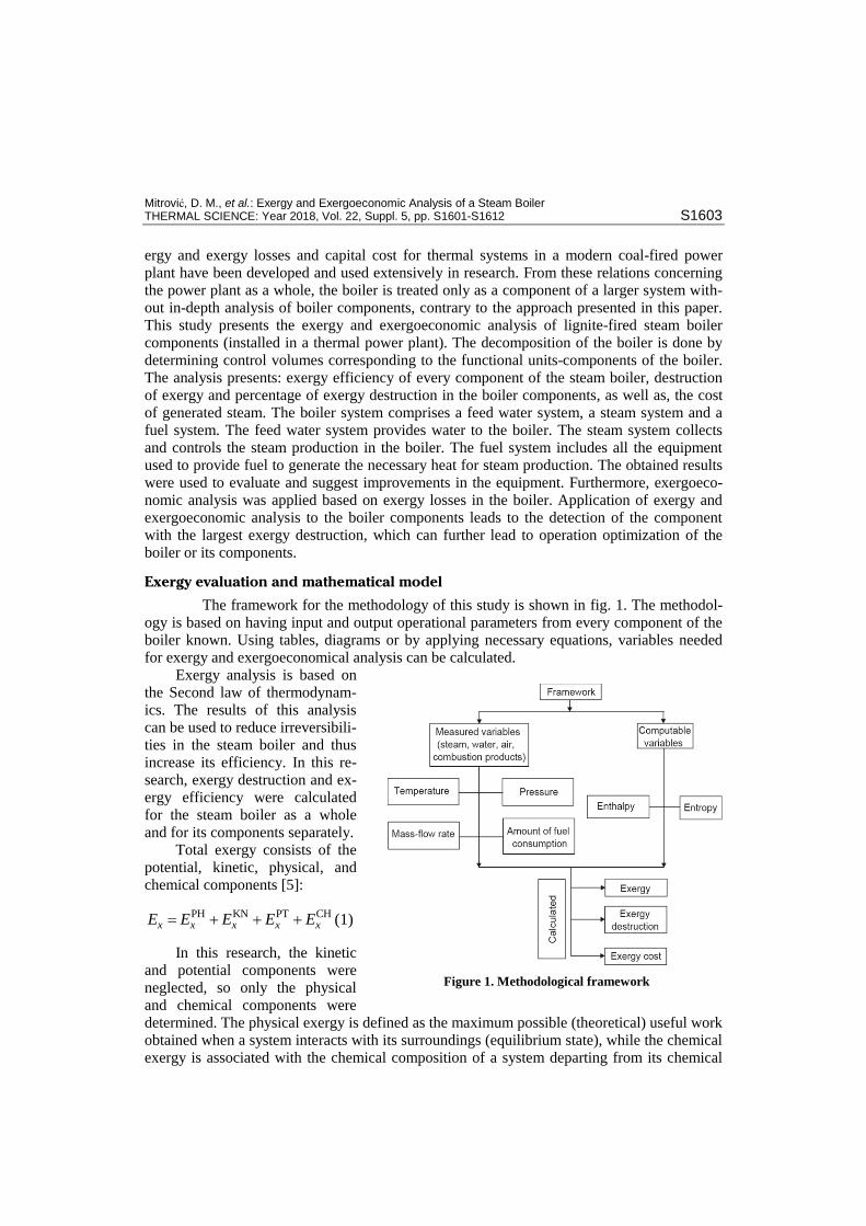
The framework for the methodology of this study is shown in fig. 1. The methodol-
ogy is based on having input and output operational parameters from every component of the
boiler known. Using tables, diagrams or by applying necessary equations, variables needed
for exergy and exergoeconomical analysis can be calculated.
Exergy analysis is based on
the Second law of thermodynam-
ics. The results of this analysis
can be used to reduce irreversibili-
ties in the steam boiler and thus
increase its efficiency. In this re-
search, exergy destruction and ex-
ergy efficiency were calculated
for the steam boiler as a whole
and for its components separately.
Total exergy consists of the
potential, kinetic, physical, and
chemical components [5]:
PH KN PT CHx x x x xE E E E E (1)
In this research, the kinetic
and potential components were
neglected, so only the physical
and chemical components were
determined. The physical exergy is defined as the maximum possible (theoretical) useful work
obtained when a system interacts with its surroundings (equilibrium state), while the chemical
exergy is associated with the chemical composition of a system departing from its chemical
Figure 1. Methodological framework
Mitrović, D. M., et al.: Exergy and Exergoeconomic Analysis of a Steam Boiler S1604 THERMAL SCIENCE: Year 2018, Vol. 22, Suppl. 5, pp. S1601-S1612
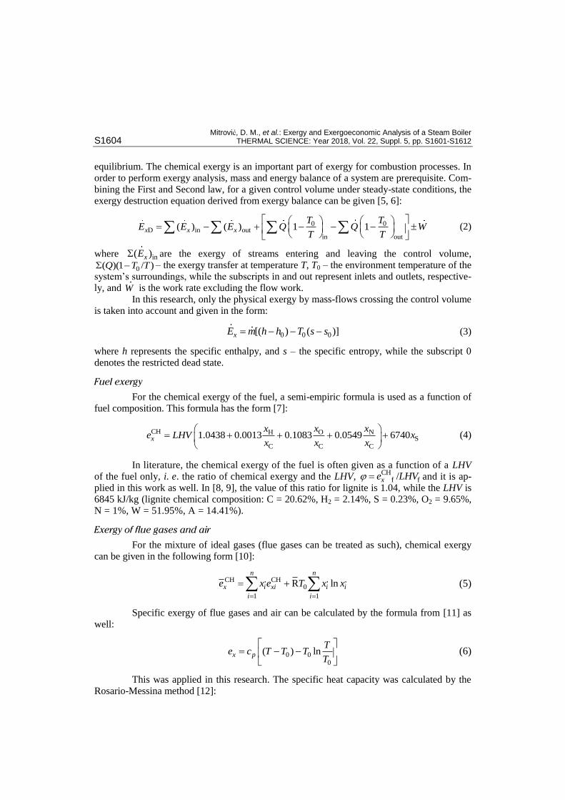
equilibrium. The chemical exergy is an important part of exergy for combustion processes. In
order to perform exergy analysis, mass and energy balance of a system are prerequisite. Com-
bining the First and Second law, for a given control volume under steady-state conditions, the
exergy destruction equation derived from exergy balance can be given [5, 6]:
0 0D in out
in out
( ) ( ) 1 1x x x
T TE E E Q Q W
T T
(2)
where in( )xE are the exergy of streams entering and leaving the control volume,
0( )(1 / )Q T T – the exergy transfer at temperature T, T0 – the environment temperature of the
system’s surroundings, while the subscripts in and out represent inlets and outlets, respective-
ly, and W is the work rate excluding the flow work.
In this research, only the physical exergy by mass-flows crossing the control volume
is taken into account and given in the form:
0 0 0[( ) ( )]xE m h h T s s (3)
where h represents the specific enthalpy, and s – the specific entropy, while the subscript 0
denotes the restricted dead state.
Fuel exergy
For the chemical exergy of the fuel, a semi-empiric formula is used as a function of
fuel composition. This formula has the form [7]:
CH O NHS
C C C
1.0438 0.0013 0.1083 0.0549 6740x
x xxe LHV x
x x x
(4)
In literature, the chemical exergy of the fuel is often given as a function of a LHV
of the fuel only, i. e. the ratio of chemical exergy and the LHV, CH
f f/xe LHV and it is ap-
plied in this work as well. In [8, 9], the value of this ratio for lignite is 1.04, while the LHV is
6845 kJ/kg (lignite chemical composition: C = 20.62%, H2 = 2.14%, S = 0.23%, O2 = 9.65%,
N = 1%, W = 51.95%, A = 14.41%).
Exergy of flue gases and air
For the mixture of ideal gases (flue gases can be treated as such), chemical exergy
can be given in the following form [10]:
CH , CH , ,
0
1 1
R lnn n
x i xi i i
i i
e x e T x x
(5)
Specific exergy of flue gases and air can be calculated by the formula from [11] as
well:
0 00
( ) lnx p
Te c T T T
T
(6)
This was applied in this research. The specific heat capacity was calculated by the
Rosario-Messina method [12]:

Mitrović, D. M., et al.: Exergy and Exergoeconomic Analysis of a Steam Boiler THERMAL SCIENCE: Year 2018, Vol. 22, Suppl. 5, pp. S1601-S1612 S1605
5* 1 1
0
( ) (ln ) [Jmol K ]ip i
i
c T a T
(7)
where T* = T/T0 and ai are coefficients from [12].
Parameters of the surroundings
For exergy analysis it is very important to select proper parameters of the surround-
ings (state of surroundings). These parameters refer to reference pressure and reference tem-
perature, but also to the composition of air. Several models can be found in literature, but
most common is to use 293.15 K for reference temperature and 1013 mbar for reference pres-
sure. Reference air composition is given in tab. 1.
Table 1. Mole fractions and chemical exergy of the reference components in atmospheric air, [5]
Component N2 O2 CO2 H2O (g)
Mole fraction, [%] 77.48 20.59 0.03 1.9
Chemical exergy, [Jmol–1] 720.00 3970.00 19480.00 9500.00
Exergy efficiency
There are numerous ways to formulate exergy efficiency for different facilities and
components, and they can be found in [13].
In this paper, the ratio of total exergy at the system outlet and total exergy at the sys-
tem inlet is treated by exergy efficiency. Exergy efficiency is defined [14]:
,out
Ex
,in
exergyin products
totalexergyinput
x
x
E
E (8)
Cost-balance equations – exergoeconomic model
The Second law of thermodynamics, in combination with economic theory repre-
sents a powerful tool for exploring problems related to energy systems. This particular com-
bination of disciplines is a relatively new field (technique) of science and engineering, called
thermoeconomics (exergoeconomics). Exergoeconomics has the following characteristics:
– it combines exergy with economic theory to obtain relevant results and
– it recognizes exergy, not energy, as a fundamental variable for energy system analysis.
By applying exergoeconomics, the cost of a particular product (in our case live
steam) of an energy system is calculated by taking into account all the costs associated with
the system operation, as well as the cost of the investment.
The cost balance equation applied to the kth
component shows that the sum of cost
rates related to all leaving exergy streams is equal to the sum of cost rates of all entering exer-
gy streams and the cost rate of capital investment and operation and maintenance costs (de-
noted as B ).Z
For a boiler operating in the steady-state, the cost balance equation has the form:
s g f a feedwater B [ $/s]C C C C C Z US (9)
where C [US$/s] is the exergy cost flow rate, ,xC cE c [US$/kJ] – the specific exergy cost,
E [kW] – the exergy flow rate.

Mitrović, D. M., et al.: Exergy and Exergoeconomic Analysis of a Steam Boiler S1606 THERMAL SCIENCE: Year 2018, Vol. 22, Suppl. 5, pp. S1601-S1612
In order to express the investment cost of equipment in terms of design parameters
in eq. (9), several methods have been proposed. For this research, cost functions suggested by
Ameri et al. [15] are adopted. For converting capital investment to cost per time unit, the fol-
lowing equation is used:
B B [US$/s]3600
Z Z CRFN
(10)
where ZB [$] is the cost of the boiler (purchase cost), N is the annual operation hours of the
unit, φ (1.06) is the maintenance factor, and CRF is the capital recovery factor. The ZB was
determined using the following relation [15]:
2B 1 b SH/RH( )
cp TZ c m (11)
where
s
3
exp ,ep
p p
c
2
45
1 exp ,eT
T Tc
c
6
B
B
11
1
c
s SH RH RHRHSH/RH
s b RH
1 i e i
e
T T T Tm
T m T
, 1 208582 $/(kg/s),c 2 0.8,c 28 bar,ep
3 150 bar,c 4 5,c 866 K,eT
5 10.42 K,c B 0.9, 6 7c
The CRF depends on the interest rate and
the expected equipment lifetime. The CRF was
determined using the equation:
(1 )
(1 ) 1
n
n
i iCRF
i
(12)
where i (7%) is the interest rate, and n (20
years) is the total expected operating period of
the system in years.
Description of the steam boiler
In this research, a one-chamber, mem-
brane-welded (SULZER) boiler with forced cir-
culation is studied. Boiler construction enables
operation with both constant and variable pres-
sure. The boiler is mono-draught with two re-
heaters. The boiler can be divided into two parts
heightwise. The lower part consists of the com-
bustor (combustion chamber), a part of the
evaporator and the wall superheater. The upper
part which sits on the combustor has following
heat exchange surfaces: the outlet superheater
(superheater III), reheater II, superheater II,
Figure 2. Schematic of the steam boiler; APH – air heater, ECO – economizer, RH – reheater, SH – superheater, CC – combustion chamber, EVA – evaporator, HPT – high-pressure steam turbine, MPT – medium-pressure steam turbine
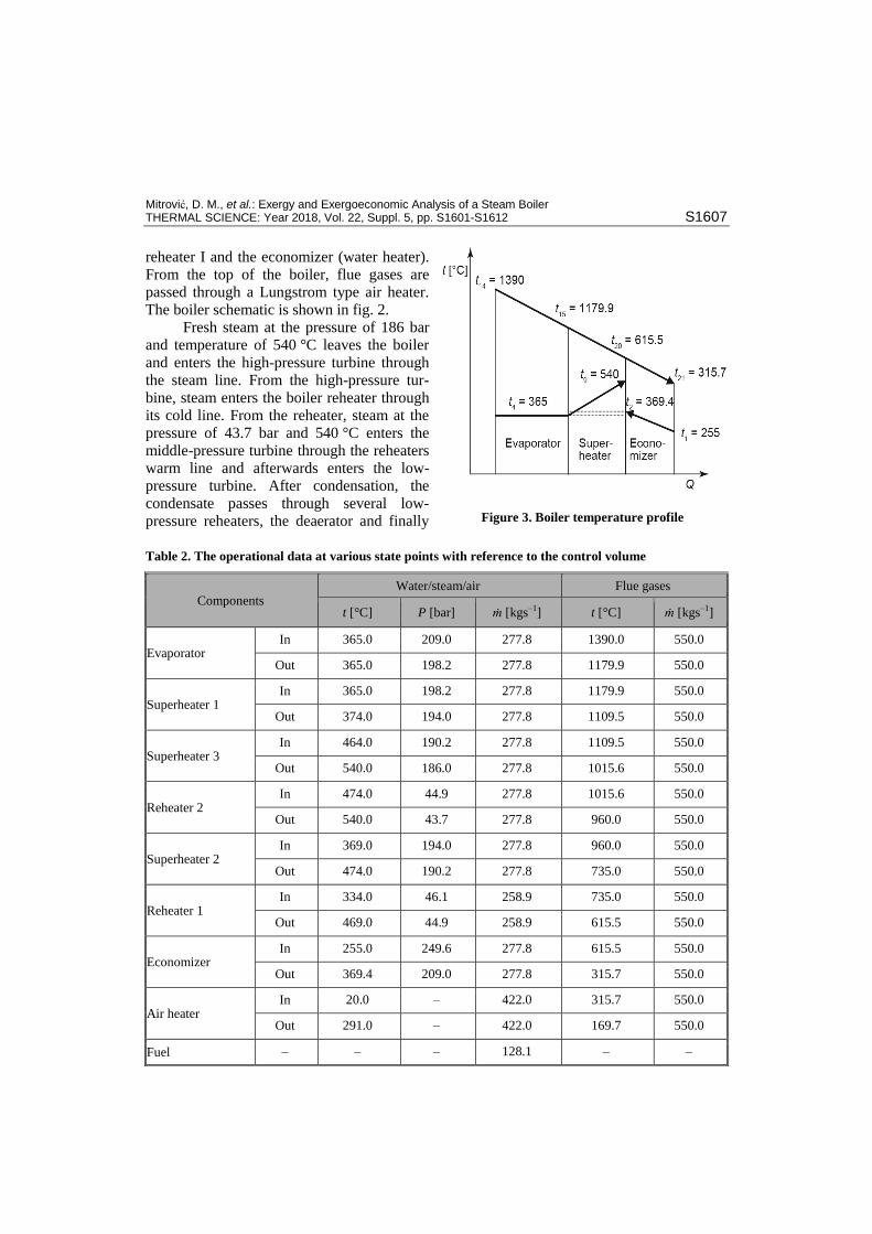
Mitrović, D. M., et al.: Exergy and Exergoeconomic Analysis of a Steam Boiler THERMAL SCIENCE: Year 2018, Vol. 22, Suppl. 5, pp. S1601-S1612 S1607
reheater I and the economizer (water heater).
From the top of the boiler, flue gases are
passed through a Lungstrom type air heater.
The boiler schematic is shown in fig. 2.
Fresh steam at the pressure of 186 bar
and temperature of 540 °C leaves the boiler
and enters the high-pressure turbine through
the steam line. From the high-pressure tur-
bine, steam enters the boiler reheater through
its cold line. From the reheater, steam at the
pressure of 43.7 bar and 540 °C enters the
middle-pressure turbine through the reheaters
warm line and afterwards enters the low-
pressure turbine. After condensation, the
condensate passes through several low-
pressure reheaters, the deaerator and finally
Table 2. The operational data at various state points with reference to the control volume
Components
Water/steam/air Flue gases
t [°C] P [bar] ṁ [kgs–1] t [°C] ṁ [kgs–1]
Evaporator In 365.0 209.0 277.8 1390.0 550.0
Out 365.0 198.2 277.8 1179.9 550.0
Superheater 1 In 365.0 198.2 277.8 1179.9 550.0
Out 374.0 194.0 277.8 1109.5 550.0
Superheater 3 In 464.0 190.2 277.8 1109.5 550.0
Out 540.0 186.0 277.8 1015.6 550.0
Reheater 2 In 474.0 44.9 277.8 1015.6 550.0
Out 540.0 43.7 277.8 960.0 550.0
Superheater 2 In 369.0 194.0 277.8 960.0 550.0
Out 474.0 190.2 277.8 735.0 550.0
Reheater 1 In 334.0 46.1 258.9 735.0 550.0
Out 469.0 44.9 258.9 615.5 550.0
Economizer In 255.0 249.6 277.8 615.5 550.0
Out 369.4 209.0 277.8 315.7 550.0
Air heater In 20.0 – 422.0 315.7 550.0
Out 291.0 – 422.0 169.7 550.0
Fuel – – – 128.1 – –
Figure 3. Boiler temperature profile
Mitrović, D. M., et al.: Exergy and Exergoeconomic Analysis of a Steam Boiler S1608 THERMAL SCIENCE: Year 2018, Vol. 22, Suppl. 5, pp. S1601-S1612
enters the feedwater tank (reservoir). Water from the feedwater tank is circulated by feed
pumps through the high-pressure heater, first entering the economizer and afterwards the
mixer, where it is mixed with water from the steam separator. From the mixer, water is cir-
culated towards the evaporator by circulating pumps. Table 2 summarizes the boiler opera-
tion parameters (state variables for all streams in the boiler). The temperature profile of the
boiler is given in fig. 3.
The boiler generates 1000.00 tons per hour of live steam, using lignite as primary fuel.
Results and discussion
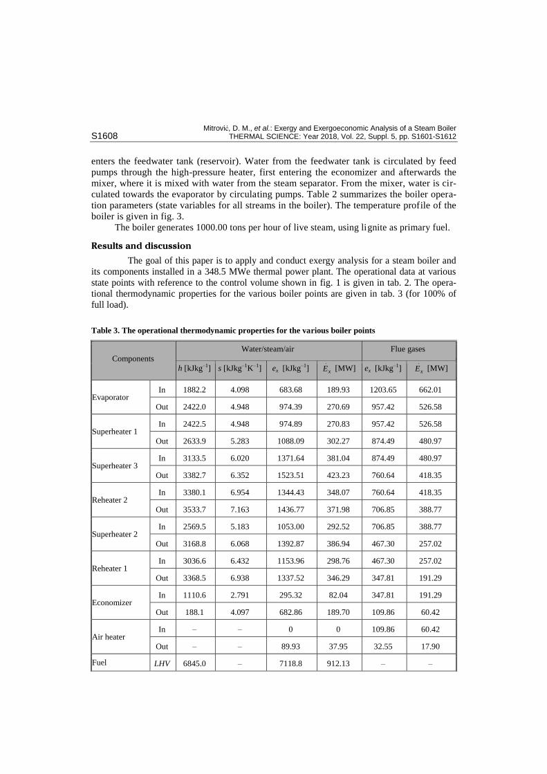
The goal of this paper is to apply and conduct exergy analysis for a steam boiler and
its components installed in a 348.5 MWe thermal power plant. The operational data at various
state points with reference to the control volume shown in fig. 1 is given in tab. 2. The opera-
tional thermodynamic properties for the various boiler points are given in tab. 3 (for 100% of
full load).
Table 3. The operational thermodynamic properties for the various boiler points
Components
Water/steam/air Flue gases
h [kJkg–1] s [kJkg–1K–1] ex [kJkg–1] xE [MW] ex [kJkg–1] xE [MW]
Evaporator In 1882.2 4.098 683.68 189.93 1203.65 662.01
Out 2422.0 4.948 974.39 270.69 957.42 526.58
Superheater 1 In 2422.5 4.948 974.89 270.83 957.42 526.58
Out 2633.9 5.283 1088.09 302.27 874.49 480.97
Superheater 3 In 3133.5 6.020 1371.64 381.04 874.49 480.97
Out 3382.7 6.352 1523.51 423.23 760.64 418.35
Reheater 2 In 3380.1 6.954 1344.43 348.07 760.64 418.35
Out 3533.7 7.163 1436.77 371.98 706.85 388.77
Superheater 2 In 2569.5 5.183 1053.00 292.52 706.85 388.77
Out 3168.8 6.068 1392.87 386.94 467.30 257.02
Reheater 1 In 3036.6 6.432 1153.96 298.76 467.30 257.02
Out 3368.5 6.938 1337.52 346.29 347.81 191.29
Economizer In 1110.6 2.791 295.32 82.04 347.81 191.29
Out 188.1 4.097 682.86 189.70 109.86 60.42
Air heater In – – 0 0 109.86 60.42
Out – – 89.93 37.95 32.55 17.90
Fuel LHV 6845.0 – 7118.8 912.13 – –

Mitrović, D. M., et al.: Exergy and Exergoeconomic Analysis of a Steam Boiler THERMAL SCIENCE: Year 2018, Vol. 22, Suppl. 5, pp. S1601-S1612 S1609
The exergy destruction rate and the exergy efficiency for each component and for
the whole boiler, fig. 2, are presented in tab. 4.
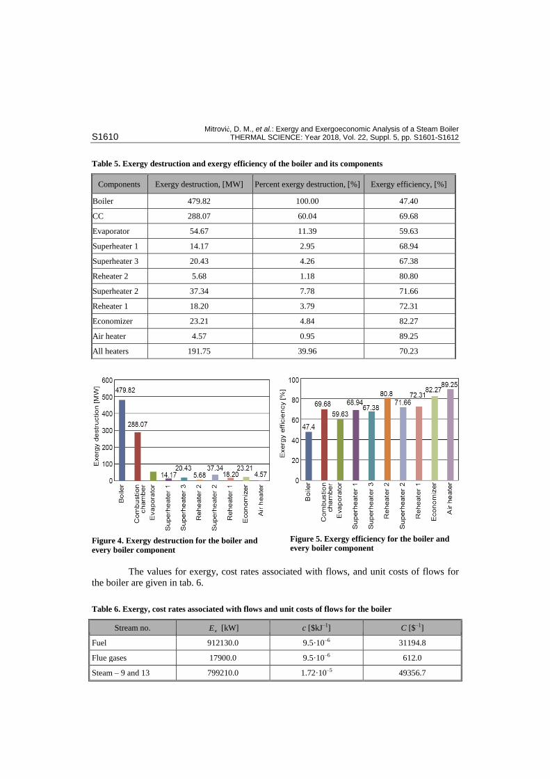
Exergy, percent of exergy destruction and exergy efficiencies are summarized in
tab. 5.
The results show that the investigated boiler has exergy destruction of 479.82 MW,
fig. 4, out of which 60.04% falls on the combustor (288.07 MW). Exergy efficiencies for the
boiler and the combustor are 47.40% and 69.68%, respectively, tab. 5, fig. 5, for 100% of full
load. All other heat exchangers, observed individually, have a significantly lower contribution
to exergy destruction (up to 11%). The exergy destruction rate of all the heaters is 39.96%,
while the corresponding exergy efficiencies were found to be 70.23%.
In this paper, exergoeconomics is applied following exergy analysis, in order to cal-
culate the exergy cost of live steam by solving the exergoeconomic balance equation, eq. (9),
assuming the specific exergy cost of feed water and air to be zero. The investment cost of the
boiler, eq. (10) is B 0.1934 $/s 696.33 $/s.Z
Table 4. The exergy destruction rate and exergy efficiency equations for the boiler and its components
Components Stream Exergy destruction Exergy efficiency
Boiler In 23, f, 1, 10
D,B f in,B out,Bx x x xE E E E Ex f D,B f( )/x x xE E E Out 9, 13 ,22
CC In 24, f
D,CC in,CC out,CCx x xE E E Ex,CC out,CC in,CC/x xE E Out 14
EVA In 14, 3
D,EVA in,EVA out,EVAx x xE E E Ex,EVA product input/x xE E Out 15, 4
SH 1 In 15, 4
D,SH1 in,SH1 out,SH1x x xE E E Ex,SH1 product input/x xE E Out 16, 5
SH 3 In 16, 8
D,SH3 in,SH3 out,SH3x x xE E E Ex,SH3 product input/x xE E Out 17, 9
RH 2 In 17, 12
D,RH2 in,RH2 out,RH2x x xE E E Ex,RH2 product input/x xE E Out 18, 13
SH 2 In 18, 6
D,SH2 in,SH2 out,SH2x x xE E E Ex,SH2 product input/x xE E Out 19, 7
RH 1 In 19, 10
D,RH1 in,RH1 out,RH1x x xE E E Ex,RH1 product input/x xE E Out 20, 11
ECO In 20, 1
D,ECO in,ECO out,ECOx x xE E E Ex,ECO product input/x xE E Out 21, 2
APH In 21, 23
D,APH in,APH out,APHx x xE E E Ex,APH product input/x xE E Out 22, 24
Mitrović, D. M., et al.: Exergy and Exergoeconomic Analysis of a Steam Boiler S1610 THERMAL SCIENCE: Year 2018, Vol. 22, Suppl. 5, pp. S1601-S1612
The values for exergy, cost rates associated with flows, and unit costs of flows for
the boiler are given in tab. 6.
Table 5. Exergy destruction and exergy efficiency of the boiler and its components
Components Exergy destruction, [MW] Percent exergy destruction, [%] Exergy efficiency, [%]
Boiler 479.82 100.00 47.40
CC 288.07 60.04 69.68
Evaporator 54.67 11.39 59.63
Superheater 1 14.17 2.95 68.94
Superheater 3 20.43 4.26 67.38
Reheater 2 5.68 1.18 80.80
Superheater 2 37.34 7.78 71.66
Reheater 1 18.20 3.79 72.31
Economizer 23.21 4.84 82.27
Air heater 4.57 0.95 89.25
All heaters 191.75 39.96 70.23
Table 6. Exergy, cost rates associated with flows and unit costs of flows for the boiler
Stream no. xE [kW] c [$kJ–1] C [$–1]
Fuel 912130.0 9.5·10–6 31194.8
Flue gases 17900.0 9.5·10–6 612.0
Steam – 9 and 13 799210.0 1.72·10–5 49356.7
Figure 4. Exergy destruction for the boiler and
every boiler component
Figure 5. Exergy efficiency for the boiler and every boiler component
Mitrović, D. M., et al.: Exergy and Exergoeconomic Analysis of a Steam Boiler THERMAL SCIENCE: Year 2018, Vol. 22, Suppl. 5, pp. S1601-S1612 S1611
Conclusion
The results of exergy analysis conducted on a coal-fired, steam boiler serving a 348.5
MWe thermal power plant were presented in this paper. Exergy analysis implies calculating ex-
ergy destruction and exergy efficiency for both the boiler and its heat exchanging components.
The results show that the exergy destruction in the boiler is 479.82 MW, out of
which the combustion chamber is responsible for 288.07 MW (60.04%) of exergy destruction.
This may be due to the irreversibility inherent in the combustion processes, heat loss, and in-
complete combustion. The exergy destruction in the boiler components ranges from 4.5 MW
to 55 MW, i. e. from 1% to 11%, which represents a small loss, individually. It is the result of
the irreversibility during heat transfer and can be used for pre-heating air used in the combus-
tion. However, it has to be noted that part of this irreversibility cannot be avoided due to the
physical, technological, and economic constraints of this study. The boiler performance can
be significantly improved by implementing the combustion process optimization. The ob-
tained research results comply with the results from other authors [4, 16-18]: the boiler exergy
efficiency is around 40%, the combustor exergy efficiency around 65%, and the heat ex-
changers exergy efficiency around 70%.
By applying the exergoeconomic analysis of the boiler, the exergy cost of live
steam is calculated at the value of 1.72·10–5
$/kJ. The results obtained in this research com-
ply with the results from other authors [19, 20]. The cost of produced steam dominantly de-
pends on fuel cost (nearly 90%), and in smaller amount on cost of capital investment. This
shows that the cost of produced steam can be reduced either by lowering fuel cost or, more
likely, by reducing fuel consumption with increasing boiler efficiency through optimization
of combustion process. The later statement is viable due to large exergy loss in combustion
chamber.
Nomenclature
CRF – capital recovery factor cp – specific heat, [kJkg–1K–1]
xE – exergy flow rate, [kW] ex – specific exergy, [kJkg–1] h – specific enthalpy, [kJkg–1] LHV – lower heating value, [kJ kg–1] M – molar mass, [kgkmol–1] ṁ – mass-flow rate, [kgs–1] R – the universal gas constant, [kJkmol–1K–1] s – specific entropy, [kJkg–1K–1] T – temperature, [K] W – power x – mass fraction
ix – volume percent of the component gas k
Greek symbol
ηEx – exergy efficiency
Subscripts
a – air B – boiler D – destruction f – fuel g – flue gas in – inlet out – outlet s – steam 0 – reference state
References
[1] Talatappeh, M. A., Gazikhani, M., Exergy Analysis in Boiler of an Experimental Power Plant, Proceed-ings, Conference on Applications and Design in Mechanical Engineering, Kangar, Perlis, Malaysia, 2007
[2] Gulhane, S. J., Thakur, A. K., Exergy Analysis of Boiler in Cogeneration Thermal Power Plant, Ameri-can Journal of Engineering Research, 2 (2013), 10, pp. 385-392
[3] Hada, P. S., Shah, I. H., First Law and Second Law Analysis of a Lignite Fired Boiler Used in a 30 MWe Thermal Power Plant, International Journal of Engineering and Innovative Technology, 1 (2012), 5, pp. 84-88
Mitrović, D. M., et al.: Exergy and Exergoeconomic Analysis of a Steam Boiler S1612 THERMAL SCIENCE: Year 2018, Vol. 22, Suppl. 5, pp. S1601-S1612
[4] Pattanayak, L., Ayyagari, S. K., Use of Energy and Exergy Analysis in Coal Fired Boiler, International Journal of Multidisciplinary Sciences and Engineering, 5 (2014), 3, pp. 17-23
[5] Bejan, A., et al., Thermal Design and Optimization, John Wiley & Sons Interscience, New York, USA, 1996
[6] Kotas, T. J., The Exergy Method of Thermal Plant Analysis, Malabar, Krieger Publishing Company, Malabar, Fla., USA, 1995
[7] Zaleta-Aguilar, A., et al. Concept on Thermoeconomic Evaluation of Steam Turbines, Appl. Therm. Eng., 27 (2007), 2-3, pp. 457-466
[8] Boonnasa, S., Namprakai, P., Exergy Evaluation of the EGAT (Block 1) Combined Cycle Power Plant, Proceedings, The Joint International Conference on Sustainable Energy and Environment, Hua Hin, Thailand, 2004, Vol. 1-3, pp. 437-441
[9] Camdali, U., Edger, V., Optimization of Fossil Fuel Sources: an Exergy Approach, Energy Sources, Part A, 29 (2007), 3, pp. 251–259
[10] Ahmadi, P., et al., Exergy, Exergoeconomic and Environmental Analyses and Evolutionary Algorithm Based Multi-Objective Optimization of Combined Cycle Power Plants, Energy, 36 (2011), 10, pp. 5886-5898
[11] Dias, R. A., Balestieri, J. A. P., Energetic and Exergetic Analysis in a Firewood Boiler, Revista dr Cien-cia&Tecnologia, 12 (2004), 23, pp. 15-24
[12] Lanzafame, R., Messina, M., Thermodynamic Property Models for Unburned Mixtures and Combustion Gases, Int. J. Thermodyn., 9 (2006), 2, pp. 73-80
[13] Cornelissen, R. L., Thermodynamics and Sustainable Development: the Use of Exergy Analysis and the Reduction of Irreversibility, Ph. D. thesis, University of Twente, Enschede, The Netherlands, 1997
[14] Mohammadkhani, F., et al., Effect of Ambient Temperature on Exergetic and Exergoeconomic Parame-ters of a CHP System, Journal of Environmentally Friendly Processes, 1 (2013), 3, pp. 28-37
[15] Ameri, M., et al., Energy, Exergy and Exergoeconomic Analysis of a Steam Power Plant: a Case Study, Int. J. Energy Res., 33 (2009), 5, pp. 499-512
[16] Ganapathy, T., et al., Exergy Analysis of Operating Lignite Fired Thermal Power Plant, J. Eng. Sci. Technol. Rev., 2 (2009), 1, pp. 123-130
[17] Vučković, G., et al., Splitting the Total Exergy Destruction into Endogenous and Exogenous Parts of the Thermal Processes in a Real Industrial Plant, Facta Universitatis Series: Mechanical Engineering, 14 (2016), 2, pp. 199-208
[18] Tumen, O. F. N., Tantekin, A., Exergoeconomic Analysis of a Fluidized Bed Coal Combustion Steam Power Plant, Thermal Science, 21 (2017), 5, pp. 1975-1984
[19] Ion, I., Ion, S., Effect of Energy Modernisation of a Steam Boiler on the Economic Efficiency, Procced-ings, Annual Conference of the Universitz of Rousse, Ruse, Bulgaria, 2013, Vol. 52, Series 1.2, pp. 26-31
[20] Mukesh, G., Raj, K., Exergoeconomic Analysis of a Boiler for a Coal Fired Thermal Power Plant, Am. J. Mech. Eng., 2 (2014), 5, pp. 143-146
Paper submitted: Mary 27, 2018 © 2018 Society of Thermal Engineers of Serbia. Paper revised: October 17, 2018 Published by the Vinča Institute of Nuclear Sciences, Belgrade, Serbia. Paper accepted: October 20, 2018 This is an open access article distributed under the CC BY-NC-ND 4.0 terms and conditions.