EXERGY ANALYSIS OF RESIDENTIAL HEATING SYSTEMS ... · EXERGY ANALYSIS OF RESIDENTIAL HEATING...
8
EXERGY ANALYSIS OF RESIDENTIAL HEATING SYSTEMS: PERFORMANCE OF WHOLE SYSTEM VS PERFORMANCE OF MAJOR EQUIPMENT XinYu Wu 1 and Radu Zmeureanu 2 1 Stantec Consulting Ltd. Winnipeg Manitoba, CANADA 2 Centre for Building Studies, Department of Building, Civil and Environmental Engineering, Faculty of Engineering and Computer Science Concordia University, Montréal, Québec, CANADA ABSTRACT This paper presents the evaluation of energy and exergy performance of several design alternatives of residential heating systems for a house. All component-based models, written and solved in the Engineering Equation Solver (EES) program, are assembled in several design alternatives for the heating, ventilation and domestic hot water (HEAT- DHW) systems. An energy-efficient house in Montreal is used as a case study. The following indices are used for assessing the overall performance of the selected systems at winter peak design conditions: energy efficiency, exergy efficiency, entropy generation, exergy destruction, energy demand, and exergy demand. INTRODUCTION The energy performance of HVAC systems is usually evaluated based on the first law of thermodynamics. The energy analysis alone is not adequate to gain a full understanding of all the important aspects of energy utilization processes, if the quality of available energy is not considered. Sometimes it misses the important aspects for improvement (Schmidt 2003). Exergy, an important thermodynamic concept, is defined as the maximum possible useful work that a system can deliver when it undergoes a reversible process from the initial state to the state of its environment, the dead state. Exergy measures the quality and quantity of energy. In a process or system, the total amount of exergy is not conserved but is destroyed due to internal irreversibilities and heat transfer crossing the system boundaries. The exergy destruction is proportional to the entropy created due to irreversibilities associated with the process (Cegel and Boles 2002). Using exergy, different types of energy sources, such as solar energy, geothermal energy, fossil fuel energy and electricity, can be compared to each other (Dincer et al. 2004). Exergy is used as a single commodity to aggregate the power generated or lost by different components of a system. Contrary to the system operating energy cost, the exergy is not affected by geo-political or market conditions. The exergy modeling techniques have been applied to various industrial sectors and thermal processes (Dincer et al. 2004). In relation to the energy analysis of buildings, Rosen et al. (2001) expressed the opinion that one major weakness in the building modeling and simulation is the lack of using the second law analysis and exergy modeling techniques. Exergy analyses have been performed to evaluate the performance of heating systems and their components in the Annex 37 (IEA Annex 37 2002). The results have shown that: there is enormous waste of exergy, when electricity is used for space heating; low quality energy tasks such as space heating can be provided more efficiently and less expensively by other means, such as geothermal energy and solar energy; ground source heat pumps are an excellent way to make use of the low quality heat from the ground to provide for the low quality energy demand of space heating (Leskinen et al. 2000). A few applications of the exergy analysis to the HVAC systems found in the literature are listed in this section: Shukuya and Komuro 1996, Asada and Takeda (2002), Badescu (2002), Ren et al. (2002), Kanoglu et al. (2004), Li et al. (2004), Zmeureanu and Zheng 2008, Zhentao and Zmeureanu 2009, Pua et al. 2010, Torio et al. 2009, Lohani et al. 2010, Sakulpipatsin et al. 2010. This paper presents the evaluation of energy and exergy performance of several design alternatives of residential HEAT-DHW systems for a house. An energy-efficient house in Montreal, Canada is used as a case study. The following indices are used for assessing the overall performance of the selected systems at winter peak design conditions: energy efficiency, exergy efficiency, entropy generation, exergy destruction, energy demand, and exergy demand. COMPONENT-BASED MODELS The first step in the application of exergy analysis to the HEAT-DHW system is the representation of the system by a combination of blocks that can interact with other blocks and their surroundings. A block represents a component of the system. Once a block diagram is generated and the system boundaries defined, it is possible to assess the mass, Proceedings of Building Simulation 2011: 12th Conference of International Building Performance Simulation Association, Sydney, 14-16 November. - 390 -
Transcript of EXERGY ANALYSIS OF RESIDENTIAL HEATING SYSTEMS ... · EXERGY ANALYSIS OF RESIDENTIAL HEATING...
EXERGY ANALYSIS OF RESIDENTIAL HEATING SYSTEMS: PERFORMANCE
OF WHOLE SYSTEM VS PERFORMANCE OF MAJOR EQUIPMENT
XinYu Wu1 and Radu Zmeureanu
2
1 Stantec Consulting Ltd. Winnipeg Manitoba, CANADA
2 Centre for Building Studies, Department of Building, Civil and Environmental Engineering,
Faculty of Engineering and Computer Science
Concordia University, Montréal, Québec, CANADA
ABSTRACT
This paper presents the evaluation of energy and
exergy performance of several design alternatives
of residential heating systems for a house. All
component-based models, written and solved in the
Engineering Equation Solver (EES) program, are
assembled in several design alternatives for the
heating, ventilation and domestic hot water (HEAT-
DHW) systems. An energy-efficient house in
Montreal is used as a case study. The following
indices are used for assessing the overall
performance of the selected systems at winter peak
design conditions: energy efficiency, exergy
efficiency, entropy generation, exergy destruction,
energy demand, and exergy demand.
INTRODUCTION
The energy performance of HVAC systems is
usually evaluated based on the first law of
thermodynamics. The energy analysis alone is not
adequate to gain a full understanding of all the
important aspects of energy utilization processes, if
the quality of available energy is not considered.
Sometimes it misses the important aspects for
improvement (Schmidt 2003).
Exergy, an important thermodynamic concept, is
defined as the maximum possible useful work that a
system can deliver when it undergoes a reversible
process from the initial state to the state of its
environment, the dead state. Exergy measures the
quality and quantity of energy. In a process or
system, the total amount of exergy is not conserved
but is destroyed due to internal irreversibilities and
heat transfer crossing the system boundaries. The
exergy destruction is proportional to the entropy
created due to irreversibilities associated with the
process (Cegel and Boles 2002). Using exergy,
different types of energy sources, such as solar
energy, geothermal energy, fossil fuel energy and
electricity, can be compared to each other (Dincer
et al. 2004). Exergy is used as a single commodity
to aggregate the power generated or lost by
different components of a system. Contrary to the
system operating energy cost, the exergy is not
affected by geo-political or market conditions.
The exergy modeling techniques have been applied
to various industrial sectors and thermal processes
(Dincer et al. 2004). In relation to the energy
analysis of buildings, Rosen et al. (2001) expressed
the opinion that one major weakness in the building
modeling and simulation is the lack of using the
second law analysis and exergy modeling
techniques.
Exergy analyses have been performed to evaluate
the performance of heating systems and their
components in the Annex 37 (IEA Annex 37 2002).
The results have shown that: there is enormous
waste of exergy, when electricity is used for space
heating; low quality energy tasks such as space
heating can be provided more efficiently and less
expensively by other means, such as geothermal
energy and solar energy; ground source heat pumps
are an excellent way to make use of the low quality
heat from the ground to provide for the low quality
energy demand of space heating (Leskinen et al.
2000).
A few applications of the exergy analysis to the
HVAC systems found in the literature are listed in
this section: Shukuya and Komuro 1996, Asada and Takeda (2002), Badescu (2002), Ren et al. (2002),
Kanoglu et al. (2004), Li et al. (2004), Zmeureanu
and Zheng 2008, Zhentao and Zmeureanu 2009,
Pua et al. 2010, Torio et al. 2009, Lohani et al.
2010, Sakulpipatsin et al. 2010.
This paper presents the evaluation of energy and
exergy performance of several design alternatives
of residential HEAT-DHW systems for a house. An
energy-efficient house in Montreal, Canada is used
as a case study. The following indices are used for
assessing the overall performance of the selected
systems at winter peak design conditions: energy
efficiency, exergy efficiency, entropy generation,
exergy destruction, energy demand, and exergy
demand.
COMPONENT-BASED MODELS
The first step in the application of exergy analysis
to the HEAT-DHW system is the representation of
the system by a combination of blocks that can
interact with other blocks and their surroundings. A
block represents a component of the system. Once a
block diagram is generated and the system
boundaries defined, it is possible to assess the mass,
Proceedings of Building Simulation 2011: 12th Conference of International Building Performance Simulation Association, Sydney, 14-16 November.
- 390 -
helenbennetts
Line
energy, entropy and exergy balances based on first
principle and correlation–based models from
product data. The models for all the blocks are
assembled together in order to represent the whole
HEAT-DHW system. Then the system can be
simulated to derive the entropy generation and
exergy destruction in each component and in the
whole system.
Selection of the EES program
Mathematical models of 25 components of
residential heating, ventilation and domestic hot
water (HEAT-DHW) systems were developed
during this study based on thermodynamic
formulation of quasi-steady-state processes (Cegel
and Boles 2002), with some exceptions where the
reference is indicated. The models were
implemented in the Engineering Equation Solver
(EES) environment (Klein 2003).
There is no commercially available software to
perform this kind of analysis on the selected
systems. The EES is an ideal environment to
develop mathematical models of HVAC
components and systems based on the second law,
since it was developed for thermodynamic
applications. The thermodynamic properties of
large number of working fluids are available by
calling built-in functions. For instance, the entropy
of water can be obtained in terms of two
independent parameters, by using the following call
function: s1=entropy(water,T=T1, P=P1). Since
the EES is a programming environment and not an
energy analysis program, there are not pre-defined
heating components and systems available, and
therefore the user must write every equation of
mathematical models using an English-like
language, in a similar way some researchers
develop some computer programs using a Fortran
or C++ language. The EES automatically identifies
and groups equations that are solved
simultaneously. Another feature offered by the EES
is the diagram window that is used by the user to
generate a graphical user interface; it may contain a
schematic diagram of the system or it may be used
for providing selected input data and displaying
some results.
Models of HEAT-DHW systems and components
Six different design alternatives of HEAT-DHW
systems are selected (Table 1) using some of the
following components: earth tube heat exchanger
(ETHEx); air-to-air heat exchanger (AAHEx);
electric or hot water air heater; electric or hot water
baseboard heater; radiant heating floor; domestic
hot water tank; air source heat pump (ASHP); gas-
fired boiler; fan; and pump.
The thermodynamic properties (e.g., temperature
and entropy) of air, water and refrigerant streams
are calculated every hour at important points of the
systems, for instance for the water leaving the
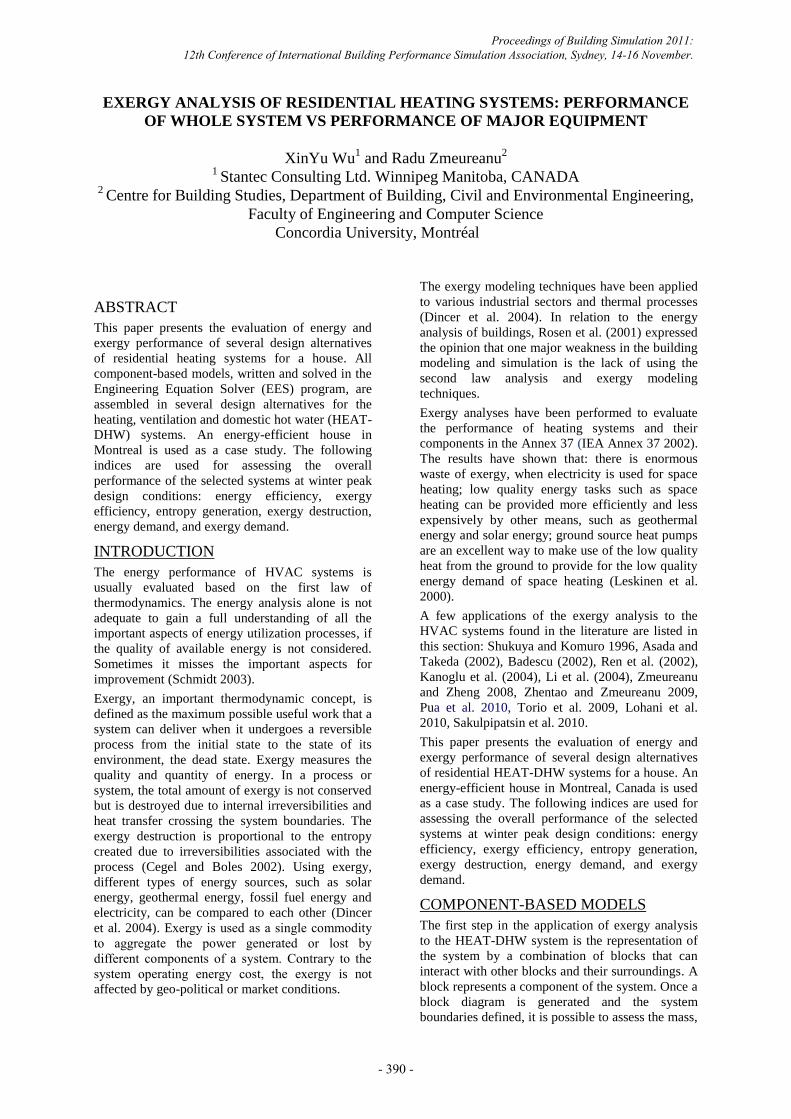
evaporator. The flowchart of design alternative no.3
is presented, as an example, in Figure 1. The
electric demand of the electric compressor, pumps
and fans is satisfied by the electricity mix, which is
represented in Figure 1 by a power plant.
Power generation is included in this analysis to
reflect the use of primary resources. For instance, in
Quebec the contribution of energy sources to the
off-site electricity generation is: hydro-electricity
96.7%; natural gas 1.1%; oil 1.1%; nuclear 1.1%
(Baouendi 2003). The overall energy efficiency of
the power plant is assumed to be as follows: coal-
fired power plant: 37% (Rosen 2001); natural gas-
fired power plant 43.1% (AIE 1998); oil-fired
power plant 33% (Kannan 2004); nuclear power
plant: 30% (Rosen 2001); hydro power plant: 80%
(Ileri and Gurer 1998). The transmission and
distribution loss is 14%, while the remaining 86%
is supplied to the end users (Zhang 1995).
Table 2 presents sample formulas used in the
performance evaluation. A few comments are made
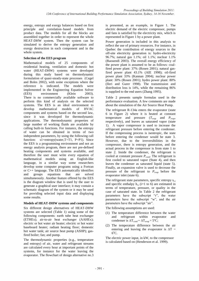
about the simulation of the Air Source Heat Pump.
The refrigerant R-134a enters the evaporator (state
6 in Figure 2) where it is heated at constant
temperature and pressure (Tevap and Pevap,
respectively), and leaves as saturated vapor (state
1). A vapor compressor is used to increase the
refrigerant pressure before entering the condenser.
If the compressing process is isentropic, the state
before entering the condenser would be state 3.
However, due to the irreversibilities in the
compressor, there is entropy generation, and the
actual process in the compressor is from state 1 to
state 2. Inside the condenser, the refrigerant is
cooled at constant pressure Pcond. The refrigerant is
first cooled to saturated vapor (State 4), and then
leaves the condenser as saturated liquid (state 5).
Finally, an expansion valve is used to decrease the
pressure of the refrigerant to Pevap before the
evaporator inlet (state 6).
The refrigerant state parameters, specific entropy sr,i
and specific enthalpy hr,i (i=1 to 6) are estimated in
terms of temperature, pressure, or quality in the
case of saturated state. In Table 2 the refrigerant
parameters have the subscript “r”, the water
parameters have the subscript “w”, and the air
parameters have the subscript “air”.
The following assumptions are used:
(1) The temperature difference between the water
and refrigerant within evaporator and
condenser is ΔTcond = ΔTevap = 5ºC;
(2) The temperature difference between the air
entering and leaving the evaporator is ΔT =
6oC.
The electric power input, in kW, to the compressor
is calculated based on (Henderson et al. 1999).
Proceedings of Building Simulation 2011: 12th Conference of International Building Performance Simulation Association, Sydney, 14-16 November.
- 391 -
RESULTS AND DISCUSSION
A house with the total floor area of 310 m2, located
in Montreal, is used as a case study. The house was
designed and built with the goal of being energy-
efficient, and exceeds the minimum values
prescribed by Quebec regulations (Kassab et al.
2003). The hourly heating loads were obtained from
the simulation of the existing house with the
BLAST program, and input to the EES
environment. The peak thermal loads used in this
study are as follows: the peak space heating load is
11.1 kW, calculated at (-23˚C) outdoor air
temperature, the DHW load is 2.3 kW, and the
heating of ventilation air is 3.9 kW. The outdoor air
temperature was considered as the reference (dead)
state for the exergy calculation. The flame
temperature of natural gas-fired hot water boiler is
selected as 2200 K (Bennett 2002).
A series of simulation programs were developed on
the EES platform to perform the second law
analysis for the six models presented in Table 1.
Overall performance of the HVAC-DHW
systems
Table 3 presents the overall results for design
alternatives No.1 to No.6 at winter peak design
conditions. Design alternative No.4 has the highest
energy efficiency of 81.2%, the design alternative
No.5 has the highest exergy efficiency of 14.8%.
Design alternative No.1
Design alternative No.1 has electric baseboard
heaters for space heating and electric domestic
water heater. There is no mechanical ventilation
system. The energy efficiency is 65.9% while the
exergy efficiency is only 10.3%.
The electric baseboard heater and electric DHW
tank account for 9.44 kW (52.1%) and 1.87 kW
(10.3%) of exergy destruction, respectively. The
power generation and transmission accounts for
6.81 kW of exergy destruction (37.6%). If
electricity is replaced by low temperature hot water,
the exergy destruction in the electric baseboard
heater and electric DHW tank would be reduced.
Design alternative No.2
Compared to design alternative No. 1, this design
alternative has a mechanical ventilation system. The
heating of ventilation outdoor air to the indoor air
temperature adds 5.32 kW of exergy destruction to
the case no.1, plus 2.70 kW at the power generation
and transmission. Consequently, both energy
energy efficiency and exergy efficiency are smaller
than in the first case.
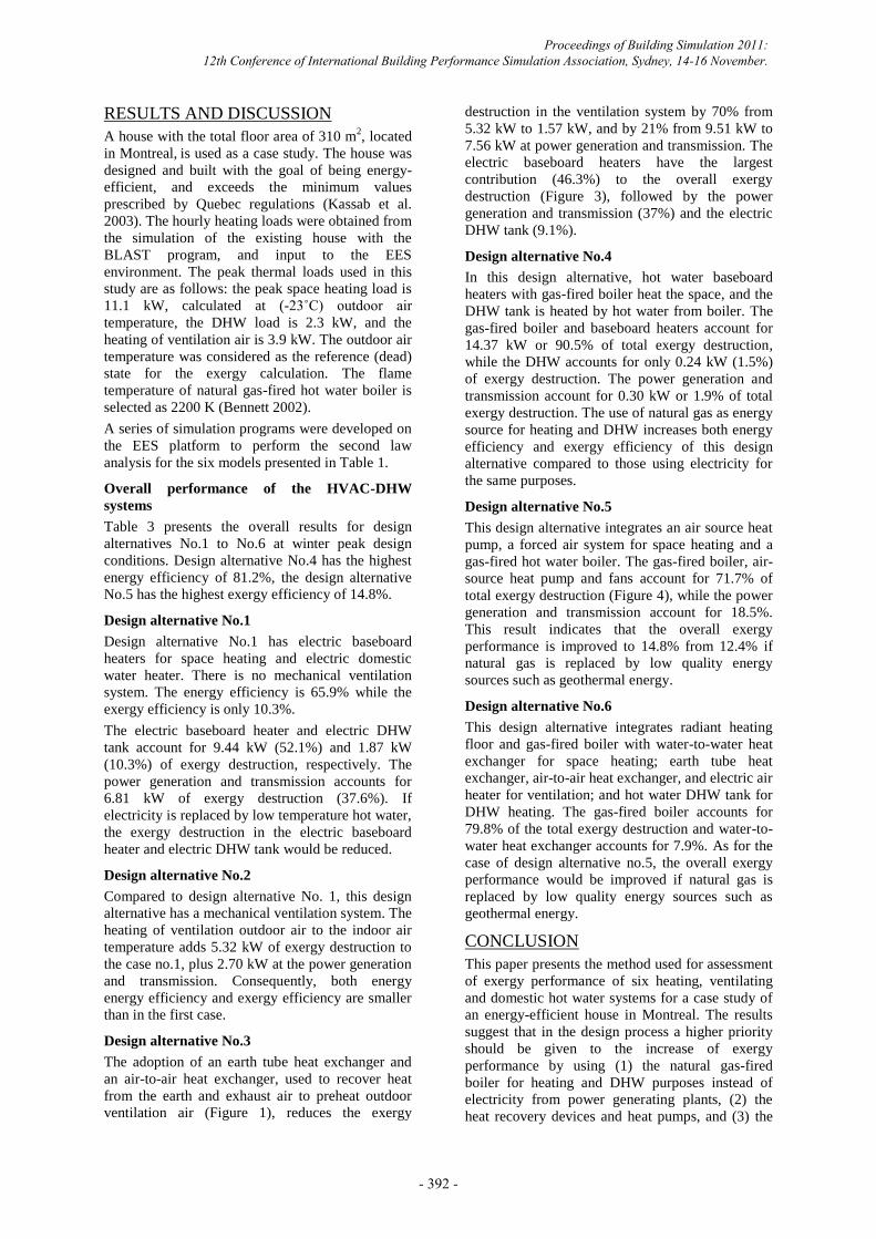
Design alternative No.3
The adoption of an earth tube heat exchanger and
an air-to-air heat exchanger, used to recover heat
from the earth and exhaust air to preheat outdoor
ventilation air (Figure 1), reduces the exergy
destruction in the ventilation system by 70% from
5.32 kW to 1.57 kW, and by 21% from 9.51 kW to
7.56 kW at power generation and transmission. The
electric baseboard heaters have the largest
contribution (46.3%) to the overall exergy
destruction (Figure 3), followed by the power
generation and transmission (37%) and the electric
DHW tank (9.1%).
Design alternative No.4
In this design alternative, hot water baseboard
heaters with gas-fired boiler heat the space, and the
DHW tank is heated by hot water from boiler. The
gas-fired boiler and baseboard heaters account for
14.37 kW or 90.5% of total exergy destruction,
while the DHW accounts for only 0.24 kW (1.5%)
of exergy destruction. The power generation and
transmission account for 0.30 kW or 1.9% of total
exergy destruction. The use of natural gas as energy
source for heating and DHW increases both energy
efficiency and exergy efficiency of this design
alternative compared to those using electricity for
the same purposes.
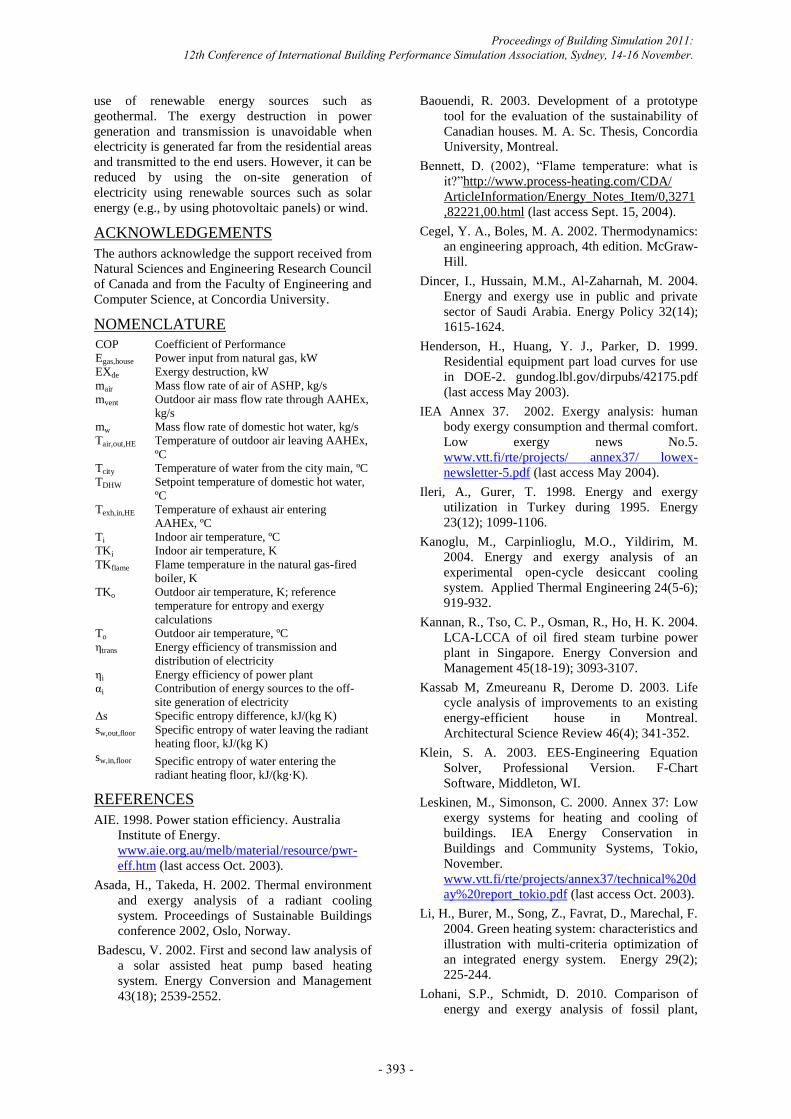
Design alternative No.5
This design alternative integrates an air source heat
pump, a forced air system for space heating and a
gas-fired hot water boiler. The gas-fired boiler, air-
source heat pump and fans account for 71.7% of
total exergy destruction (Figure 4), while the power
generation and transmission account for 18.5%.
This result indicates that the overall exergy
performance is improved to 14.8% from 12.4% if
natural gas is replaced by low quality energy
sources such as geothermal energy.
Design alternative No.6
This design alternative integrates radiant heating
floor and gas-fired boiler with water-to-water heat
exchanger for space heating; earth tube heat
exchanger, air-to-air heat exchanger, and electric air
heater for ventilation; and hot water DHW tank for
DHW heating. The gas-fired boiler accounts for
79.8% of the total exergy destruction and water-to-
water heat exchanger accounts for 7.9%. As for the
case of design alternative no.5, the overall exergy
performance would be improved if natural gas is
replaced by low quality energy sources such as
geothermal energy.
CONCLUSION
This paper presents the method used for assessment
of exergy performance of six heating, ventilating
and domestic hot water systems for a case study of
an energy-efficient house in Montreal. The results
suggest that in the design process a higher priority
should be given to the increase of exergy
performance by using (1) the natural gas-fired
boiler for heating and DHW purposes instead of
electricity from power generating plants, (2) the
heat recovery devices and heat pumps, and (3) the
Proceedings of Building Simulation 2011: 12th Conference of International Building Performance Simulation Association, Sydney, 14-16 November.
- 392 -
use of renewable energy sources such as
geothermal. The exergy destruction in power
generation and transmission is unavoidable when
electricity is generated far from the residential areas
and transmitted to the end users. However, it can be
reduced by using the on-site generation of
electricity using renewable sources such as solar
energy (e.g., by using photovoltaic panels) or wind.
ACKNOWLEDGEMENTS
The authors acknowledge the support received from
Natural Sciences and Engineering Research Council
of Canada and from the Faculty of Engineering and
Computer Science, at Concordia University.
NOMENCLATURE
COP
Egas,house
EXde
mair
Coefficient of Performance
Power input from natural gas, kW
Exergy destruction, kW
Mass flow rate of air of ASHP, kg/s
mvent
mw
Outdoor air mass flow rate through AAHEx,
kg/s
Mass flow rate of domestic hot water, kg/s
Tair,out,HE Temperature of outdoor air leaving AAHEx,
ºC
Tcity
TDHW
Texh,in,HE
Ti
TKi
TKflame
TKo
To
ηtrans
ηi
αi
Δs
sw,out,floor
sw,in,floor
Temperature of water from the city main, ºC
Setpoint temperature of domestic hot water,
ºC
Temperature of exhaust air entering
AAHEx, ºC
Indoor air temperature, ºC
Indoor air temperature, K
Flame temperature in the natural gas-fired
boiler, K
Outdoor air temperature, K; reference
temperature for entropy and exergy
calculations
Outdoor air temperature, ºC
Energy efficiency of transmission and
distribution of electricity
Energy efficiency of power plant
Contribution of energy sources to the off-
site generation of electricity
Specific entropy difference, kJ/(kg K)
Specific entropy of water leaving the radiant
heating floor, kJ/(kg K)
Specific entropy of water entering the
radiant heating floor, kJ/(kg·K).
REFERENCES
AIE. 1998. Power station efficiency. Australia
Institute of Energy.
www.aie.org.au/melb/material/resource/pwr-
eff.htm (last access Oct. 2003).
Asada, H., Takeda, H. 2002. Thermal environment
and exergy analysis of a radiant cooling
system. Proceedings of Sustainable Buildings
conference 2002, Oslo, Norway.
Badescu, V. 2002. First and second law analysis of
a solar assisted heat pump based heating
system. Energy Conversion and Management
43(18); 2539-2552.
Baouendi, R. 2003. Development of a prototype
tool for the evaluation of the sustainability of
Canadian houses. M. A. Sc. Thesis, Concordia
University, Montreal.
Bennett, D. (2002), “Flame temperature: what is
it?”http://www.process-heating.com/CDA/
ArticleInformation/Energy_Notes_Item/0,3271
,82221,00.html (last access Sept. 15, 2004).
Cegel, Y. A., Boles, M. A. 2002. Thermodynamics:
an engineering approach, 4th edition. McGraw-
Hill.
Dincer, I., Hussain, M.M., Al-Zaharnah, M. 2004.
Energy and exergy use in public and private
sector of Saudi Arabia. Energy Policy 32(14);
1615-1624.
Henderson, H., Huang, Y. J., Parker, D. 1999.
Residential equipment part load curves for use
in DOE-2. gundog.lbl.gov/dirpubs/42175.pdf
(last access May 2003).
IEA Annex 37. 2002. Exergy analysis: human
body exergy consumption and thermal comfort.
Low exergy news No.5.
www.vtt.fi/rte/projects/ annex37/ lowex-
newsletter-5.pdf (last access May 2004).
Ileri, A., Gurer, T. 1998. Energy and exergy
utilization in Turkey during 1995. Energy
23(12); 1099-1106.
Kanoglu, M., Carpinlioglu, M.O., Yildirim, M.
2004. Energy and exergy analysis of an
experimental open-cycle desiccant cooling
system. Applied Thermal Engineering 24(5-6);
919-932.
Kannan, R., Tso, C. P., Osman, R., Ho, H. K. 2004.
LCA-LCCA of oil fired steam turbine power
plant in Singapore. Energy Conversion and
Management 45(18-19); 3093-3107.
Kassab M, Zmeureanu R, Derome D. 2003. Life
cycle analysis of improvements to an existing
energy-efficient house in Montreal.
Architectural Science Review 46(4); 341-352.
Klein, S. A. 2003. EES-Engineering Equation
Solver, Professional Version. F-Chart
Software, Middleton, WI.
Leskinen, M., Simonson, C. 2000. Annex 37: Low
exergy systems for heating and cooling of
buildings. IEA Energy Conservation in
Buildings and Community Systems, Tokio,
November.
www.vtt.fi/rte/projects/annex37/technical%20d
ay%20report_tokio.pdf (last access Oct. 2003).
Li, H., Burer, M., Song, Z., Favrat, D., Marechal, F.
2004. Green heating system: characteristics and
illustration with multi-criteria optimization of
an integrated energy system. Energy 29(2);
225-244.
Lohani, S.P., Schmidt, D. 2010. Comparison of
energy and exergy analysis of fossil plant,
Proceedings of Building Simulation 2011: 12th Conference of International Building Performance Simulation Association, Sydney, 14-16 November.
- 393 -

ground and air source heat pump building
heating system. Renewable Energy 35; 1275–
1282.
Pua, J., Liub, G., Feng, X. 2010. Application of the
cumulative exergy approach to different air
conditioning systems. Energy and Buildings
42; 1999-2004.
Ren, C., Li, N., Tang, G. 2002. Principle of exergy
in HVAC and evaluation of evaporative
cooling schemes. Building and Environment
37; 1045-1055.
Rosen, M.A., Leong, W. H., Le, M. N. 2001.
Modeling and analysis of building systems that
integrate cogeneration and district heating and
cooling. Proceedings of eSim Conference,
Ottawa, Canada; 187-194.
Rosen, M. A. 2001. Energy- and exergy-based
comparison of coal-fired and nuclear steam
power plants. Exergy, an International Journal
1(3); 180-192.
Sakulpipatsin, P., Itard, L.C.M., van der Kooi, H.J.,
Boelman, E.C., Luscuere, P.G. 2010. An
exergy application for analysis of buildings and
HVAC systems. Energy and Buildings 42; 90–
99.
Schmidt, D. 2003. Design of low exergy buildings-
method and a pre-design tool. International
Journal of Low Energy and Sustainable
Buildings. www.byv.kth.se/avd/byte/leas (last
access Oct. 2004).
Shukuya, M., Komuro, D. 1996. Exergy-entropy
process of solar heating and global
environmental system. Solar Energy 58(1-3);
25-32.
Torio, H., Angelotti, A., Schmidt, D. 2009. Exergy
analysis of renewable energy-based
climatisation systems for buildings: A critical
viewEnergy and Buildings 41; 248–271.
Zhang, M. 1995. Analysis of energy conversion
systems including material and global warming
aspects. Ph. D Thesis, Oregon State University.
Zhentao, W., Zmeureanu, R. 2009. Exergy Analysis
of Variable Air Volume Systems for an Office
Building. Energy Conversion and Management
50; 387-392.
Zmeureanu, R.,,Zheng, X. 2008. Second law
analysis of the water loop heat pump system
for office buildings. World Renewable Energy
Congress X, Glasgow.
Figure 1 Configuration of design alternative No.3
Power plant
Exhaust
air
Outdoor air
Electric DHW
tank
Electric baseboard
heater
Electric air heater
Earth tube
heat
exchanger
Air-to-air heat
exchanger
Fan
Proceedings of Building Simulation 2011: 12th Conference of International Building Performance Simulation Association, Sydney, 14-16 November.
- 394 -
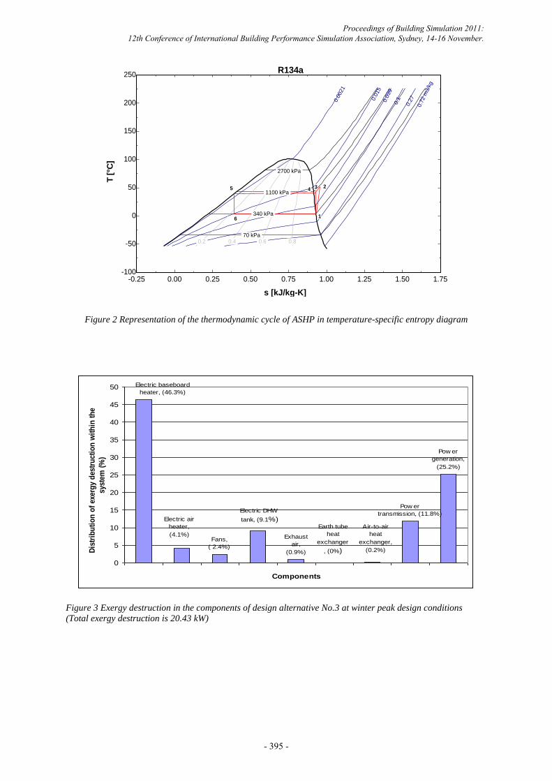
Figure 2 Representation of the thermodynamic cycle of ASHP in temperature-specific entropy diagram
Figure 3 Exergy destruction in the components of design alternative No.3 at winter peak design conditions
(Total exergy destruction is 20.43 kW)
-0.25 0.00 0.25 0.50 0.75 1.00 1.25 1.50 1.75-100
-50
0
50
100
150
200
250
s [kJ/kg-K]
T [
°C]
2700 kPa
1100 kPa
340 kPa
70 kPa 0.2 0.4 0.6 0.8
0.0
021
0.0
15
0.0
39
0.1
0.2
7
0.7
2 m
3/k
g
R134a
1
2345
6
Earth tube
heat
exchanger
, (0%)
Air-to-air
heat
exchanger,
(0.2%)
Pow er
transmission, (11.8%)
Pow er
generation,
(25.2%)
Exhaust
air,
(0.9%)
Electric DHW
tank, (9.1%)
Fans,
( 2.4%)
Electric air
heater,
(4.1%)
Electric baseboard
heater, (46.3%)
0
5
10
15
20
25
30
35
40
45
50
Components
Dis
trib
uti
on
of
exerg
y d
estr
ucti
on
wit
hin
th
e
syste
m (
%)
Proceedings of Building Simulation 2011: 12th Conference of International Building Performance Simulation Association, Sydney, 14-16 November.
- 395 -
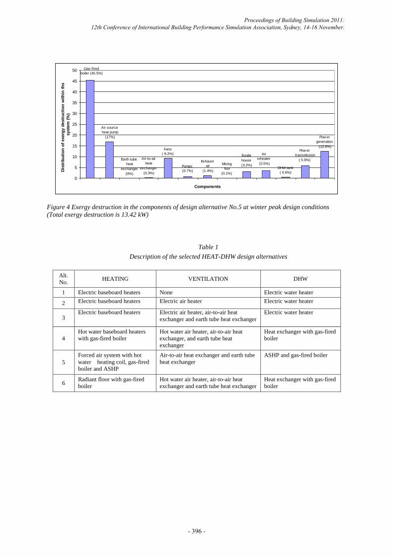
Figure 4 Exergy destruction in the components of design alternative No.5 at winter peak design conditions
(Total exergy destruction is 13.42 kW)
Table 1
Description of the selected HEAT-DHW design alternatives
Alt.
No. HEATING VENTILATION DHW
1 Electric baseboard heaters None Electric water heater
2 Electric baseboard heaters Electric air heater Electric water heater
3 Electric baseboard heaters Electric air heater, air-to-air heat
exchanger and earth tube heat exchanger
Electric water heater
4
Hot water baseboard heaters with gas-fired boiler
Hot water air heater, air-to-air heat
exchanger, and earth tube heat
exchanger
Heat exchanger with gas-fired boiler
5
Forced air system with hot
water heating coil, gas-fired boiler and ASHP
Air-to-air heat exchanger and earth tube
heat exchanger
ASHP and gas-fired boiler
6 Radiant floor with gas-fired
boiler
Hot water air heater, air-to-air heat
exchanger and earth tube heat exchanger
Heat exchanger with gas-fired
boiler
Pow er
transmission
( 5.9%)
DHW tank
( 0.6%)
Air
reheater
(3.5%)
Inside
house
(3.2%)Mixing
box
(0.1%)
Exhaust
air
(1.4%)
Pumps
(0.7%)
Air-to-air
heat
exchanger
(0.3%)
Earth tube
heat
exchanger
(0%)
Pow er
generation
(12.6%)Fans
( 9.2%)
Air source
heat pump
(17%)
Gas-fired
boiler (45.5%)
0
5
10
15
20
25
30
35
40
45
50
Components
Dis
trib
uti
on
of
exerg
y d
estr
ucti
on
wit
hin
th
s
syste
m (
%)
Proceedings of Building Simulation 2011: 12th Conference of International Building Performance Simulation Association, Sydney, 14-16 November.
- 396 -
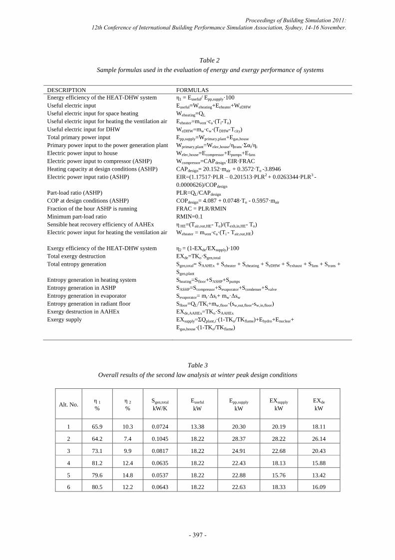
Table 2
Sample formulas used in the evaluation of energy and exergy performance of systems
DESCRIPTION FORMULAS
Energy efficiency of the HEAT-DHW system
Useful electric input
η1 = Euseful/ Epp,supply·100
Euseful=Weheating+Eeheater+WeDHW
Useful electric input for space heating Weheating=QL
Useful electric input for heating the ventilation air Eeheater=mvent·ca·(Ti-To)
Useful electric input for DHW WeDHW=mw·cw·(TDHW-Tcity)
Total primary power input Epp,supply=Wprimary,plant+Egas,house
Primary power input to the power generation plant Wprimary,plant=Welec,house/ηtrans·Σαi/ηi
Electric power input to house Welec,house=Ecompressor+Epumps+Efans
Electric power input to compressor (ASHP)
Heating capacity at design conditions (ASHP)
Wcompressor=CAPdesign·EIR·FRAC
CAPdesign= 20.152·mair + 0.3572·To -3.8946
Electric power input ratio (ASHP) EIR=(1.17517·PLR – 0.201513·PLR2 + 0.0263344·PLR3 -
0.0000626)/COPdesign
Part-load ratio (ASHP) PLR=QL/CAPdesign
COP at design conditions (ASHP)
Fraction of the hour ASHP is running
Minimum part-load ratio
Sensible heat recovery efficiency of AAHEx
Electric power input for heating the ventilation air
Exergy efficiency of the HEAT-DHW system
Total exergy destruction
Total entropy generation
Entropy generation in heating system
Entropy generation in ASHP
Entropy generation in evaporator
Entropy generation in radiant floor
Exergy destruction in AAHEx
Exergy supply
COPdesign= 4.087 + 0.0748·To - 0.5957·mair
FRAC = PLR/RMIN
RMIN=0.1
η HE=(Tair,out,HE- To)/(Texh,in,HE- To)
Weheater = mvent·ca·(Ti - Tair,out,HE)
η2 = (1-EXde/EXsupply)·100
EXde=TKo·Sgen,total
Sgen,total= SAAHEx + Seheater + Seheating + SeDHW + Sexhaust + Sfans + Strans +
Sgen,plant
Sheating=Sfloor+SASHP+Spumps
SASHP=Scompressor+Sevaporator+Scondenser+Svalve
Sevaporator= mr·Δsr+ mw·Δsw
Sfloor=QL/TKi+mw,floor·(sw,out,floor-sw,in,floor)
EXde,AAHEx=TKo·SAAHEx
EXsupply=ΣQplant,i·(1-TKo/TKflame)+Ehydro+Enuclear+
Egas,house·(1-TKo/TKflame)
Table 3
Overall results of the second law analysis at winter peak design conditions
Alt. No. η 1
%
η 2
%
Sgen,total
kW/K
Euseful
kW
Epp,supply
kW
EXsupply
kW
EXde
kW
1 65.9 10.3 0.0724 13.38 20.30 20.19 18.11
2 64.2 7.4 0.1045 18.22 28.37 28.22 26.14
3 73.1 9.9 0.0817 18.22 24.91 22.68 20.43
4 81.2 12.4 0.0635 18.22 22.43 18.13 15.88
5 79.6 14.8 0.0537 18.22 22.88 15.76 13.42
6 80.5 12.2 0.0643 18.22 22.63 18.33 16.09
Proceedings of Building Simulation 2011: 12th Conference of International Building Performance Simulation Association, Sydney, 14-16 November.
- 397 -