Exergy analysis of a combined heat and power plant with ...€¦ · Exergy analysis of a combined...
13
General rights Copyright and moral rights for the publications made accessible in the public portal are retained by the authors and/or other copyright owners and it is a condition of accessing publications that users recognise and abide by the legal requirements associated with these rights. Users may download and print one copy of any publication from the public portal for the purpose of private study or research. You may not further distribute the material or use it for any profit-making activity or commercial gain You may freely distribute the URL identifying the publication in the public portal If you believe that this document breaches copyright please contact us providing details, and we will remove access to the work immediately and investigate your claim. Downloaded from orbit.dtu.dk on: Apr 15, 2020 Exergy analysis of a combined heat and power plant with integrated lignocellulosic ethanol production Lythcke-Jørgensen, Christoffer Ernst; Haglind, Fredrik; Clausen, Lasse Røngaard Published in: Proceedings of International Conference on Efficiency, Cost, Optimization, Simulation, and Environmental Impact of Energy Systems Publication date: 2013 Link back to DTU Orbit Citation (APA): Lythcke-Jørgensen, C. E., Haglind, F., & Clausen, L. R. (2013). Exergy analysis of a combined heat and power plant with integrated lignocellulosic ethanol production. In Proceedings of International Conference on Efficiency, Cost, Optimization, Simulation, and Environmental Impact of Energy Systems Chinese Society of Engineering Thermophysics.
Transcript of Exergy analysis of a combined heat and power plant with ...€¦ · Exergy analysis of a combined...
General rights Copyright and moral rights for the publications made accessible in the public portal are retained by the authors and/or other copyright owners and it is a condition of accessing publications that users recognise and abide by the legal requirements associated with these rights.
Users may download and print one copy of any publication from the public portal for the purpose of private study or research.
You may not further distribute the material or use it for any profit-making activity or commercial gain
You may freely distribute the URL identifying the publication in the public portal If you believe that this document breaches copyright please contact us providing details, and we will remove access to the work immediately and investigate your claim.
Downloaded from orbit.dtu.dk on: Apr 15, 2020
Exergy analysis of a combined heat and power plant with integrated lignocellulosicethanol production
Lythcke-Jørgensen, Christoffer Ernst; Haglind, Fredrik; Clausen, Lasse Røngaard
Published in:Proceedings of International Conference on Efficiency, Cost, Optimization, Simulation, and EnvironmentalImpact of Energy Systems
Publication date:2013
Link back to DTU Orbit
Citation (APA):Lythcke-Jørgensen, C. E., Haglind, F., & Clausen, L. R. (2013). Exergy analysis of a combined heat and powerplant with integrated lignocellulosic ethanol production. In Proceedings of International Conference on Efficiency,Cost, Optimization, Simulation, and Environmental Impact of Energy Systems Chinese Society of EngineeringThermophysics.
Exergy analysis of a combined heat and power plant with integrated lignocellulosic ethanol
production
Christoffer Lythcke-Jørgensen a, Fredrik Haglindb and Lasse Røngaard Clausenc
a DTU Mechanical Engineering, Section for Thermal Energy, Copenhagen, Denmark, [email protected] b DTU Mechanical Engineering, Section for Thermal Energy, Copenhagen, Denmark, [email protected] c DTU Mechanical Engineering, Section for Thermal Energy, Copenhagen, Denmark, [email protected]
Abstract: Integrating second generation bioethanol production in combined heat and power units is expected to increase system energy efficiencies while producing sustainable fuel for the transportation sector at a competitive price. By applying exergy analysis, this study assessed the efficiency of an integrated system in which steam extracted from an existing combined heat and power unit is used for covering the heating demand of a lignocellulosic ethanol production facility. The integration solution was designed and optimized using already existing steam extraction points in the combined heat and power unit solely. The exergy flows inside the ethanol facility were determined, and the exergy in steam flows into and out of the system components were determined by combining exergy analysis with pinch analysis and setting a constant heat exchange temperature difference of 10K. The ethanol facility produces ethanol, solid biofuel, molasses, and is able to produce district heating hot water. Considering all products equally valuable, the exergy efficiency of the ethanol facility was found to be 0.790 during integrated operation with zero district heating production, and 0.852 during integrated operation with full district heating production. During separate operation, the exergy efficiency dropped to 0.564 with zero district heating production and 0.583 with full district heating production. The ratio of exergy losses and destruction in the heat integration network to the total exergy destruction and losses in the system was in the range of 0.46-0.87 depending on the system operation. This study suggests that a well-designed heat integration network can increase the exergy efficiency of the integrated system markedly.
Keywords: Exergy analysis, lignocellulosic ethanol production, polygeneration system, plant operation.
1. Introduction Lignocellulosic ethanol can be mixed with gasoline in order to reduce the greenhouse gas emissions from the transportation sector while decreasing the oil import dependency in countries without domestic oil reservoirs. At the same time, the production does not couple the food and energy prices in contrast to starch-based ethanol production. Lignocellulosic ethanol is therefore considered a promising second-generation biofuel by the Commission of the European Communities [1].
Due to the energy intensive nature of lignocellulosic ethanol production, production facilities are often assumed integrated in polygeneration systems. Several studies have treated systems with integrated production of power, heat, lignocellulosic ethanol, and synthetic natural gas (SNG) [2-6]. For such systems, Daianova et al. [2] and Ilic et al. [3] both report better energy economy for the integrated system compared to stand-alone systems, while Bösch et al. [4] reports a potential increase in both first law energy efficiency and exergy efficiency when integrating the processes. Modarresi et al. [5] applied pinch analysis to improve the heat integration of the system, which yielded an integrated exergy efficiency of 88% for the ethanol process. Furthermore, Gassner and Maréchal [6] has investigated process integration in the polygeneration system and concludes that both first and second law energy efficiencies for a combined heat and power (CHP) plant are increased significantly by integrating lignocellulosic ethanol and SNG production. Furthermore, a case study by Starfelt et al. [7] reports higher first-law energy efficiency for integrating lignocellulosic ethanol production in an existing CHP plant compared to a scenario with separate
production. These results all explain the industrial interest in retrofitting existing CHP units to obtain the mentioned polygeneration system benefits.
Analogue to the studies mentioned above, a previous case study by the authors [8] investigated the energy economy of a polygeneration system in which the Danish CHP unit Avedøreværket 1 (AVV1) is retrofitted by integrating a lignocellulosic ethanol production facility based on IBUS (Integrated Biomass Utilization System) technology [9-11]. It was found that the exergy flow from the CHP unit to the IBUS facility had a significant negative impact on the system economy, mainly due to the reduced power production capacity of the system. Integration design optimization was limited by stating that steam had to be extracted from existing steam extraction points only. This paper investigates the impact of the non-ideal integration solution, which is not considered in other studies of similar systems but is likely to be applied in real life plant retrofitting.
The objectives of the study are to determine the potential impact of a non-ideal integration solution in a polygeneration system, and to identify critical design challenges faced when retrofitting existing CHP units. To achieve this, the integration design of the polygeneration system previously treated by the authors [8] is addressed. Exergy analysis [12] is applied to determine irreversibilities in the heat integration network and the IBUS facility, and to identify ways of reducing the exergy flow from the CHP unit to the IBUS facility.
In this paper, the polygeneration system model and the exergy analysis approach are described in Section 2. The study results are presented in Section 3 and discussed in Section 4, while a conclusion of the study is given in Section 5.
2. Methodology
2.1. Polygeneration system model The polygeneration system was modelled previously by the authors [8]. In this section, the basic design of the system and the data necessary to carry out an exergy analysis of the IBUS facility and the integration solution are presented. A more detailed explanation of the system modelling can be found in a previous study by the authors [8].
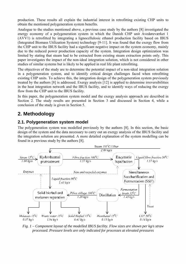
Fig. 1 – Component layout of the modelled IBUS facility. Flow sizes are shown per kg/s straw processed. Pressure levels are only indicated for processes at elevated pressures
The component layout of the modelled IBUS facility is presented in Fig. 1. The flows of yeast and enzymes are insignificant for the overall mass and energy balances of the system and were therefore not included in the model.
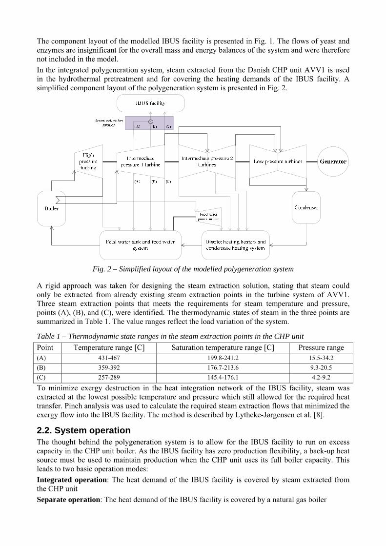
In the integrated polygeneration system, steam extracted from the Danish CHP unit AVV1 is used in the hydrothermal pretreatment and for covering the heating demands of the IBUS facility. A simplified component layout of the polygeneration system is presented in Fig. 2.
Fig. 2 – Simplified layout of the modelled polygeneration system
A rigid approach was taken for designing the steam extraction solution, stating that steam could only be extracted from already existing steam extraction points in the turbine system of AVV1. Three steam extraction points that meets the requirements for steam temperature and pressure, points (A), (B), and (C), were identified. The thermodynamic states of steam in the three points are summarized in Table 1. The value ranges reflect the load variation of the system.
Table 1 – Thermodynamic state ranges in the steam extraction points in the CHP unit
Point Temperature range [C] Saturation temperature range [C] Pressure range (A) 431-467 199.8-241.2 15.5-34.2
(B) 359-392 176.7-213.6 9.3-20.5
(C) 257-289 145.4-176.1 4.2-9.2
To minimize exergy destruction in the heat integration network of the IBUS facility, steam was extracted at the lowest possible temperature and pressure which still allowed for the required heat transfer. Pinch analysis was used to calculate the required steam extraction flows that minimized the exergy flow into the IBUS facility. The method is described by Lythcke-Jørgensen et al. [8].
2.2. System operation The thought behind the polygeneration system is to allow for the IBUS facility to run on excess capacity in the CHP unit boiler. As the IBUS facility has zero production flexibility, a back-up heat source must be used to maintain production when the CHP unit uses its full boiler capacity. This leads to two basic operation modes:
Integrated operation: The heat demand of the IBUS facility is covered by steam extracted from the CHP unit
Separate operation: The heat demand of the IBUS facility is covered by a natural gas boiler

In this study, four types of system operation schemes were investigated
i) Integrated operation with full load condensation mode operation in AVV1 and zero district heating (DH) production in the IBUS facility
ii) Integrated operation with full load back pressure mode operation in AVV1 and full DH production in the IBUS facility
iii) Separate operation with zero DH production in the IBUS facility
iv) Separate operation with full DH production in the IBUS facility
During separate operation, the heat demand in the IBUS facility is covered by steam from a gas boiler with 96% heating efficiency. Chemical properties and specific flow sizes of gas per kg/s straw processed at various operation modes are summarized in Table 2. Further details about the operational patterns of the polygeneration system are given in Lythcke-Jørgensen et al. [8].
Table 2 – Chemical properties of natural gas and specific consumption during separate operation with zero and full IBUS district heating production. Chemical properties for natural gas have been taken from [13].
Fuel Lower heating value [kJ/kg]
Chemical exergy content [kJ/kg]
Gas flow, zero IBUS DH production [kg/s]
Gas flow, full IBUS DH production [kg/s]
Natural Gas
41,426 43,497 0.270 0.325
2.3. Exergy Analysis Calculations Exergy analysis was applied to the IBUS facility and the heat integration network to identify irreversibilities, and thereby ways for reducing the exergy flow from the CHP unit to the IBUS facility. The reference point for all exergy calculations was set to 298.15 and 1 .
The total specific exergy of a material stream, , is given by the following expression:
. (1)
Here, is the specific physical exergy, is the specific kinetic exergy, is the specific potential exergy, and is the specific chemical exergy. and were not considered in the analysis as they are negligible in magnitude for the given material streams [4].
Exergy flows related to mass flows in the system, , were calculated as the total specific exergy of the material stream times the mass flow of the stream, :
∙ . (2)
Considering all useful material streams out of a component as valuable, the exergy efficiency of a system component was calculated as the exergy content in product flows, ∑ , divided by the exergy content in inlet flows, ∑ :
∑
∑. (3)
In this study, the difference between the exergy content in inlet mass flows and in product mass flows was caused partly by exergy destruction within the component, partly by exergy content in unused material flows from the component. For simplicity, these fractions were merged in a term called exergy losses and destruction, & , which is calculated as:
& ∑ ∑ . (4)
As the main product of the IBUS facility is lignocellulosic ethanol and solid fuel for combustion, the exergy efficiency for the fuel production, , , is evaluated for the whole system as well:
,
∑ ,. (5)
2.3.1. Chemical Exergy The chemical exergy of multi-component material streams, , was calculated as the sum of the chemical exergy content of the individual components , multiplied by their weight fraction :
∑ , . (6)
The chemical exergy for the material components that occur in the IBUS facility are summarized in Table 3. The values have been taken from a study by Bösch et al. [4].
2.3.2. Physical Exergy As material flows in the system occur at reference pressure, the mechanical part of the physical exergy is zero. As suggested by Bösch et al. [4], heat capacities of biomass material streams were assumed constant over the relevant temperature ranges present. The physical exergy of multi-component biomass materials was calculated according to the specific heat capacity of the material,
, and the temperature of the material, , using the following equation [12].
, ln . (7)
The heat capacity of multi-component materials were calculated as the sum of the individual components’ heat capacities multiplied by their weight fraction . Used values are presented in Table 3.
∑ . (8)
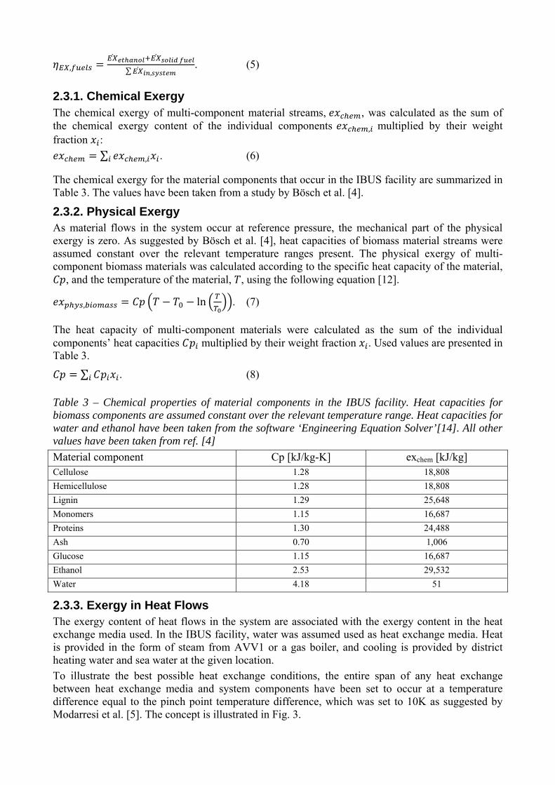
Table 3 – Chemical properties of material components in the IBUS facility. Heat capacities for biomass components are assumed constant over the relevant temperature range. Heat capacities for water and ethanol have been taken from the software ‘Engineering Equation Solver’[14]. All other values have been taken from ref. [4]
Material component Cp [kJ/kg-K] exchem [kJ/kg] Cellulose 1.28 18,808
Hemicellulose 1.28 18,808
Lignin 1.29 25,648
Monomers 1.15 16,687
Proteins 1.30 24,488
Ash 0.70 1,006
Glucose 1.15 16,687
Ethanol 2.53 29,532
Water 4.18 51
2.3.3. Exergy in Heat Flows The exergy content of heat flows in the system are associated with the exergy content in the heat exchange media used. In the IBUS facility, water was assumed used as heat exchange media. Heat is provided in the form of steam from AVV1 or a gas boiler, and cooling is provided by district heating water and sea water at the given location.
To illustrate the best possible heat exchange conditions, the entire span of any heat exchange between heat exchange media and system components have been set to occur at a temperature difference equal to the pinch point temperature difference, which was set to 10K as suggested by Modarresi et al. [5]. The concept is illustrated in Fig. 3.
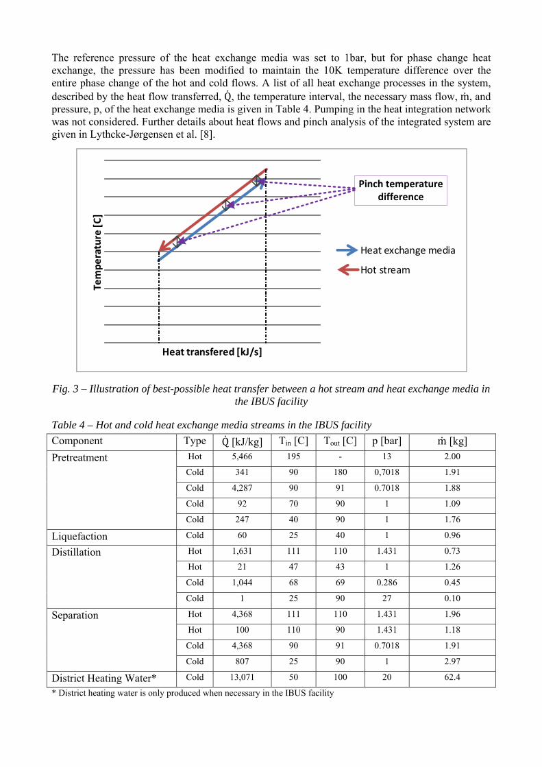
The reference pressure of the heat exchange media was set to 1bar, but for phase change heat exchange, the pressure has been modified to maintain the 10K temperature difference over the entire phase change of the hot and cold flows. A list of all heat exchange processes in the system, described by the heat flow transferred, Q, the temperature interval, the necessary mass flow, m, and pressure, p, of the heat exchange media is given in Table 4. Pumping in the heat integration network was not considered. Further details about heat flows and pinch analysis of the integrated system are given in Lythcke-Jørgensen et al. [8].
Fig. 3 – Illustration of best-possible heat transfer between a hot stream and heat exchange media in the IBUS facility
Table 4 – Hot and cold heat exchange media streams in the IBUS facility
Component Type Q [kJ/kg] Tin [C] Tout [C] p [bar] m [kg]
Pretreatment Hot 5,466 195 - 13 2.00
Cold 341 90 180 0,7018 1.91
Cold 4,287 90 91 0.7018 1.88
Cold 92 70 90 1 1.09
Cold 247 40 90 1 1.76
Liquefaction Cold 60 25 40 1 0.96
Distillation Hot 1,631 111 110 1.431 0.73
Hot 21 47 43 1 1.26
Cold 1,044 68 69 0.286 0.45
Cold 1 25 90 27 0.10
Separation Hot 4,368 111 110 1.431 1.96
Hot 100 110 90 1.431 1.18
Cold 4,368 90 91 0.7018 1.91
Cold 807 25 90 1 2.97
District Heating Water* Cold 13,071 50 100 20 62.4
* District heating water is only produced when necessary in the IBUS facility
Temperature [C]
Heat transfered [kJ/s]
Heat exchange media
Hot stream
Pinch temperature difference

3. Results Using the method described previously, the exergy flows of the integrated system were calculated. A Grassmann diagram of the exergy flows within the IBUS facility is presented in Fig. 4. The diagram shows how the exergy content of the inlet wheat straw passes through the various processes in the facility until it ends up in the final energy products: ethanol, solid fuel and molasses. The exergy flows into the system from heat transfer and power are also illustrated. Exergy losses and destruction (L&D), which cover exergy destruction in components and exergy content of discarded material streams, are illustrated as well. Exergy destruction in the system is in general related to heat transfer over a temperature difference, frictional exergy destruction, and material degradation.
The largest exergy L&D in the IBUS facility processes occurs in the Simultaneous Saccharification and Fermentation (SSF) component where the exothermal fermentation process takes place. Heat released from the fermentation is used to maintain an elevated temperature in the component, explaining the lack of heat flow into the component. L&D in this component are associated with heat losses, product degradation from the fermentation process, and exergy content of the CO2 which is discarded at an elevated temperature.
Fig. 4 – Grassmann diagram illustrating the exergy flows inside the IBUS facility per kg/s straw processed. Exergy losses and destruction (L&D) is illustrated as well
In the heat integration network, the heat exchange media is conditioned and distributed to meet the heating and cooling demands of the IBUS facility. Heating is provided by steam from AVV1 or a gas boiler, and recovered heat from the processes in the IBUS facility. Cooling is provided by sea water and by district heating water when district heating production is active in the IBUS facility.
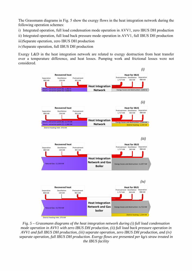
The Grassmann diagrams in Fig. 5 show the exergy flows in the heat integration network during the following operation schemes:
i) Integrated operation, full load condensation mode operation in AVV1, zero IBUS DH production
ii) Integrated operation, full load back pressure mode operation in AVV1, full IBUS DH production
iii) Separate operation, zero IBUS DH production
iv) Separate operation, full IBUS DH production
Exergy L&D in the heat integration network are related to exergy destruction from heat transfer over a temperature difference, and heat losses. Pumping work and frictional losses were not considered.
Fig. 5 – Grassmann diagrams of the heat integration network during (i) full load condensation mode operation in AVV1 with zero IBUS DH production, (ii) full load back pressure operation in AVV1 and full IBUS DH production, (iii) separate operation, zero IBUS DH production, and (iv)
separate operation, full IBUS DH production. Exergy flows are presented per kg/s straw treated in the IBUS facility
Separation988 kW
Destillation363 kW
Pretreatment1,717 kW
Heat for IBUS
Separation988 kW
Destillation363 kW
Pretreatment1,717 kW
Heat for IBUS
Separation988 kW
Destillation363 kW
Pretreatment1,717 kW
Heat for IBUS
Pretreatment901 kW
Destillation134 kW
Separation860 kW
Steam, extraction point (B): 2,182 kJSteam, extraction point (C): 1,633 kJ
Recovered heat
Pretreatment901 kW
Destillation134 kW
Separation860 kW
Steam, extraction point (B): 2,174 kW
Steam, extraction point (C): 2,366 kW
Recovered heat
Exergy losses and destruction: 1,509 kW
District heating inlet: 376 kW
District heating: 2,234 kW
(i)
(ii)
Heat Integration Network
Pretreatment901 kW
Destillation134 kW
Separation860 kW
Recovered heat
District heating inlet: 376 kW
District heating: 2,234 kW
(iv)
Pretreatment901 kW
Destillation134 kW
Separation860 kW
Natural Gas: 12,230 kW
Recovered heat
(iii)
Exergy losses and destruction: 11,057 kW
Heat Integration Network and Gas
Boiler
Natural Gas: 14,743 kW Exergy losses and destruction: 11,712 kW
Heat Integration Network and Gas
boiler
Separation988 kW
Destillation363 kW
Pretreatment1,717 kW
Heat for IBUS
Exergy losses and destruction: 2,642 kJ
Heat Integration Network

The calculated exergy efficiencies of the IBUS facility components and the heat integration network are presented in Table 5. The IBUS facility alone was found to have an exergy efficiency of 0.913, while the exergy efficiency of the heat integration network was found to be highly dependent on operation mode.
The lignocellulosic ethanol production system was found to have the highest exergy efficiencies during integrated operation. When the CHP unit was operated at full load in condensation mode, an exergy efficiency of 0.790 was obtained, while it was increased to 0.852 during full load back pressure operation in the CHP unit and with DH production in the IBUS facility. The reason for this increase is the fact that DH hot water was considered a product in the analysis. For a similar system with lignocellulosic ethanol production integrated in a CHP unit, Modarresi et al. [5] reported an exergy of 0.793 for the lignocellulosic ethanol system.
Markedly lower exergy efficiencies are obtained for the system during separate operation. Without DH production in the IBUS facility, the system was found to have an exergy efficiency of 0.564, while it was increased to 0.583 when DH production was included. This clearly illustrates the benefits of integrated operation for the system in terms of exergy efficiency.
When looking at the exergy efficiency of the fuel production solely, it is seen that integrated operation yields higher exergy efficiencies as well, while operation with DH production in the IBUS facility gives lower exergy efficiencies than for operation without DH production. The reason is that DH hot water is not included as a valuable product in the fuel production exergy efficiency, but the DH production increases the heating demand of the system slightly.
Table 5 – Exergy destruction and exergy efficiency in the IBUS facility, its processes and the heat integration network
System Exergy losses and destruction per kg/s of straw processed [kW]
ηEX [-] ηEX,fuels [-]
IBUS facility
Hydrothermal pretreatment 205 0.990 -
Liquefaction 73 0.994 -
SSF 710 0.939 -
Distillation 201 0.986 -
Separation 570 0.954 -
IBUS facility, total 1,759 0.913 0.600
Heat Integration Network
Operation mode (i) 2,642 0.550 -
Operation mode (ii) 1,509 0.725 -
Operation mode (iii) 11,057 0.217 -
Operation mode (iv) 11,712 0.312 -
Integrated System, total
Operation mode (i) 4,401 0.790 0.579
Operation mode (ii) 3,268 0.852 0.560
Operation mode (iii) 12,816 0.564 0.385
Operation mode (iv) 13,471 0.583 0.357
Depending on the operation mode, 46% to 87% of the exergy L&D in the integrated system occurs in the heat integration network. This leaves room for a significant exergy efficiency increase by optimizing this part of the system. One way would be to extract steam at conditions closer to those

needed in the heat integration network. Another way to optimize the average exergy efficiency of the system over the lifetime is to minimize the duration of separate operation in the polygeneration system. Comparing these results with the outcomes of a thermo-economic analysis of the system [8], it is suggested that a carefully designed heat integration network combined with well-placed steam extraction points can increase the production economy of the treated polygeneration system.
4. Discussion The outcomes of this study suggest that for the polygeneration system treated, the rigid approach for steam extraction when designing the heat integration network caused the exergy efficiency of the lignocellulosic ethanol production system to decrease significantly. It is therefore suggested that a more flexible approach is taken as extraction of steam at conditions closer to those that are optimal for the heat exchange will increase both the exergy efficiency and production economy of the polygeneration system. The theoretic optimal efficiency might be increased further if the pinch point temperature difference of 100C could be lowered. However, the designed heat integration network is optimal in the sense that all heat exchange occurs at a temperature difference equal to the pinch point temperature difference. This would hardly be the case in real life, and it is therefore not reasonable to assume that the exergy losses and destruction in the heat integration network calculated in this study can eliminated completely.
There are several other limitations to the efficiency increase that can be gained through the design of the heat integration network. First of all, it is not certain that steam is available at the ideal conditions for the heat exchange with the IBUS facility. The CHP unit is designed to fit the steam conditions for turbine expansion, meaning that the steam is superheated until it reaches the lower pressure levels. Opposed to this, saturated steam is optimal for heat exchange with the IBUS facility, and they might therefore not be available in the CHP unit.
Secondly, if points exist where the steam conditions are ideal for exchanging heat with the IBUS facility, it is not certain that steam can be extracted therefrom without having to replace system components, which not only poses an economical challenge for the plant owner but might in fact be infeasible as new equipment might not fit with other system components. And even if steam can be extracted from near-optimal points in the CHP unit it is not necessarily economically reasonable to do so. Investment in advanced heat integration network components and upgrading or replacement of several existing components in the CHP unit might not be justified by the increased production economy. Whether this is the case or not requires further investigations, but these points represent main challenges when retrofitting existing CHP units, and it urges a careful approach when making assumptions on benefits from retrofitting.
5. Conclusion This study treated the integrated production of heat, power and lignocellulosic ethanol in a polygeneration system based on an existing CHP unit. A rigid approach was taken when designing and optimizing the system integration, stating that steam extracted from the CHP unit could only be extracted from already existing steam extraction points. The efficiency of the lignocellulosic ethanol production facility, called the IBUS facility was evaluated using exergy analysis. At optimal heat exchange conditions, the results indicate an exergy efficiency of 0.913 for the IBUS facility. Calculations suggest an exergy efficiency of 0.790 for the integrated system with full load condensation mode operation in the CHP unit and zero DH production in the IBUS facility, and 0.852 with full load back pressure operation in the CHP unit and full DH production in the IBUS facility. During separate operation, the exergy efficiency of the lignocellulosic ethanol production decreases to 0.564 with zero DH production, and 0.583 with full DH production due to the combustion of natural gas for covering the heat demand. When only including ethanol and solid biofuel as products in the exergy analysis, the exergy efficiency of the system is suggested to be in the range 0.357-0.579 depending on operation mode. The results illustrate the benefits of maintaining integrated operation in the treated polygeneration system in terms of exergy efficiency,

but they also point out challenges associated with retrofitting existing CHP units as the heat integration network, which was optimized with respect to already existing steam extraction points in the CHP unit, was responsible for up to 87% of the exergy losses in the integrated lignocellulosic ethanol production.
Acknowledgments The authors would like to thank Brian Elmegaard for allowing the use of his numerical model of the Danish combined heat and power unit Avedøreværket 1, and for his feedback on the method used for analysing exergy flows in the system.
Nomenclature Cp specific heat capacity, kJ/(kg K)
exergy flow, kW
ex specific exergy content, kJ/kg
exchem specific chemical exergy content, kJ/kg
exkin specific kinetic exergy content, kJ/kg
exphys specific physical exergy content, kJ/kg
expot specific potential exergy content, kJ/kg
mass flow, kg/s
p pressure, bar
heat flow, kJ/s
T temperature, K
x mass fraction, -
Abbreviations
AVV1 Avedøreværket 1
CHP Combined Heat and Power
DH District Heating
L&D (exergy) Losses and Destruction
SNG Synthetic Natural Gas
SSF Simultaneous Saccharification and Fermentation
References [1] Commission of the European Communities, Communication from the Commission – An EU
Strategy for Biofuels, 2006. Available at:
<http://eur-lex.europa.eu/LexUriServ/LexUriServ.do?uri=CELEX:52006DC0034:EN:NOT> [accessed 26/02/2013]
[2] Daianova L., Dotzauer E., Thorin E., Yan J., Evaluation of a regional bioenergy system with local production of biofuel for transportation, integrated with a CHP plant. Applied Energy 2011;92:739-749.
[3] Ilic D., Dotzauer E., Trygg L., District heating and ethanol production through polygeneration in Stockholm. Applied Energy 2011;91:214-221.
[4] Bösch P., Modarresi A., Friedl A., Comparison of combined ethanol and biogas polygeneration facilities using exergy analysis. Applied Thermal Engineering 2012;37:19-29.
[5] Modarresi A., Kravanja P., Friedl A., Pinch and exergy analysis of lignocellulosic ethanol, biomethane, heat and power production from straw. Applied Thermal Engineering 2012;43:20-28.
[6] Gassner M., Maréchal F., Increasing Conversion Efficiency in Fuel Ethanol Production from Lignocellulosic Biomass by Polygeneration – and a Paradoxon between Energy and Exergy in Process Integration. In: ECOS 2010: Proceedings of the 23rd International Conference on Efficiency, Cost, Optimization, Simulation, and Environmental Impact of Energy Systems; 2010 Jun 14-17; Lausanne, Switzerland.
[7] Starfelt F., Thorin E., Dotzauer E., Performance evaluation of adding ethanol production into an existing combined heat and power plant. Bioresource Technology 2009;101:613-618.
[8] Lythcke-Jørgensen C., Haglind F., Clausen L. R., Thermodynamic and economic analysis of integrating lignocellulosic bioethanol production in a Danish combined heat and power unit. In: EU BC&E 2013: Proceedings of the 21st European Biomass Conference and Exhibition; 2013 Jun 3-7; Copenhagen, Denmark.
[9] Scott-Bentsen, N., Felby C., Ipsen K. H., Energy balance of 2nd generation bioethanol production in Denmark. Elsam A/S 2006.
[10] Larsen J., Petersen M. Ø., Thirup L., Li H. W., Iversen F. K., The IBUS process – lignocellulosic bioethanol close to a commercial reality. Chemical Engineering Technology 2008;31:765-772
[11] Larsen J., Petersen M. Ø., Thirup L., Inbicon makes lignocellulosic ethanol a commercial reality. Biomass and Bioenergy 2012;46:36-45.
[12] Bejan A., Tsatsaronis G., Moran M., Thermal Design & Optimization. New York: John Wiley & Sons, Inc.; 1996.
[13] Rian A. B., Ertesvåg I. S., Exergy evaluation of the arctic Snøhvit liquefied natural gas processing plant in northern Norway – significance of ambient temperature. Energy&Fuels 2012;26:1259-1267.
[14] F-Chart Software. Engineering Equation Solver. Available at: <http://www.fchart.com/ees/> [accessed 24/02/2013]