
Exercise 1(A) Cisco Router Setup with Serial Interfacemagda/ics_x33/lab5.docx · Web viewThe data...
33
LAB SIX In a previous lab, you learned how to configure routing table entries manually. This was referred to as static routing. The topic of Lab 6 is dynamic routing, where dynamic routing protocols (from now on, called routing protocols) set the routing tables automatically without human intervention. Routers and hosts that run routing protocols, exchange routing protocol messages related to network paths and node conditions and use these messages to compute paths between routers and hosts. Most routing protocols implement a shortest-path algorithm, which, for a given set of routers, determines the shortest paths between the routers. Some routing protocols allow for each network interface to be assigned a cost metric. In this case, routing protocols compute paths with least cost. Based on the method used to compute the shortest or least-cost paths, one distinguishes between distance vector and link state routing protocols. In a distance vector routing protocol, neighboring routers send the content of their routing tables to each other and update the routing tables based on the received routing tables. In a link state routing protocol, each router advertises the cost of each of its interfaces to all routers in the network. Thus, all routers have complete knowledge of the network topology and can locally run a shortest-path (or least-cost) algorithm to determine their own routing tables. The notion of an autonomous system (AS) is central to the understanding of routing protocols on the Internet. An autonomous system is a group of IP networks under the authority of a single administration. The entire Internet is carved up into a large number of autonomous systems. Examples of autonomous systems are the campus network of a university and the backbone network of a global network service provider. In the Internet, dynamic routing within an autonomous system (intra) and between autonomous systems (inter) is handled by different types of routing protocols. A routing protocol that is concerned with routing within an autonomous system is called an intradomain routing protocol or interior gateway protocol (IGP). A routing protocol that determines routes between autonomous systems is called an interdomain routing protocol or exterior gateway protocol (EGP).
Transcript of Exercise 1(A) Cisco Router Setup with Serial Interfacemagda/ics_x33/lab5.docx · Web viewThe data...
LAB SIXIn a previous lab, you learned how to configure routing table entries manually. This was referred to as static routing. The topic of Lab 6 is dynamic routing, where dynamic routing protocols (from now on, called routing protocols) set the routing tables automatically without human intervention. Routers and hosts that run routing protocols, exchange routing protocol messages related to network paths and node conditions and use these messages to compute paths between routers and hosts.
Most routing protocols implement a shortest-path algorithm, which, for a given set of routers, determines the shortest paths between the routers. Some routing protocols allow for each network interface to be assigned a cost metric. In this case, routing protocols compute paths with least cost. Based on the method used to compute the shortest or least-cost paths, one distinguishes between distance vector and link state routing protocols. In a distance vector routing protocol, neighboring routers send the content of their routing tables to each other and update the routing tables based on the received routing tables. In a link state routing protocol, each router advertises the cost of each of its interfaces to all routers in the network. Thus, all routers have complete knowledge of the network topology and can locally run a shortest-path (or least-cost) algorithm to determine their own routing tables.
The notion of an autonomous system (AS) is central to the understanding of routing protocols on the Internet. An autonomous system is a group of IP networks under the authority of a single administration. The entire Internet is carved up into a large number of autonomous systems. Examples of autonomous systems are the campus network of a university and the backbone network of a global network service provider. In the Internet, dynamic routing within an autonomous system (intra) and between autonomous systems (inter) is handled by different types of routing protocols. A routing protocol that is concerned with routing within an autonomous system is called an intradomain routing protocol or interior gateway protocol (IGP). A routing protocol that determines routes between autonomous systems is called an interdomain routing protocol or exterior gateway protocol (EGP).
In this lab, you study the two most common intradomain protocols, namely, the Routing Information Protocol (RIP) and the Open Shortest Path First (OSPF) protocol. Part 1-3 of this lab deal with RIP, and Part 4-5 are about OSPF. In part 6, you are exposed to a few features of the Border Gateway Protocol (BGP), which is the interdomain (EGP) routing protocol of the Internet.

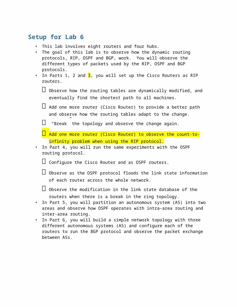
Setup for Lab 6• This lab involves eight routers and four hubs. • The goal of this lab is to observe how the dynamic routing protocols, RIP, OSPF and
BGP, work. You will observe the different types of packets used by the RIP, OSPF and BGP protocols.
• In Parts 1, 2 and 3, you will set up the Cisco Routers as RIP routers.๏ Observe how the routing tables are dynamically modified, and eventually find the
shortest path to all machines.๏ Add one more router (Cisco Router) to provide a better path and observe how the
routing tables adapt to the change.๏ “Break” the topology and observe the change again.๏ Add one more router (Cisco Router) to observe the count-to-infinity problem when
using the RIP protocol.• In Part 4, you will run the same experiments with the OSPF routing protocol.
๏ Configure the Cisco Router and as OSPF routers. ๏ Observe as the OSPF protocol floods the link state information of each router across
the whole network.๏ Observe the modification in the link state database of the routers when there is a
break in the ring topology.• In Part 5, you will partition an autonomous system (AS) into two areas and observe how
OSPF operates with intra-area routing and inter-area routing.• In Part 6, you will build a simple network topology with three different autonomous
systems (AS) and configure each of the routers to run the BGP protocol and observe the packet exchange between ASs.
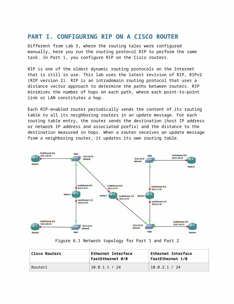
PART I. CONFIGURING RIP ON A CISCO ROUTERDifferent from Lab 3, where the routing tales were configured manually, here you run the routing protocol RIP to perform the same task. In Part 1, you configure RIP on the Cisco routers.
RIP is one of the oldest dynamic routing protocols on the Internet that is still in use. This lab uses the latest revision of RIP, RIPv2 (RIP version 2). RIP is an intradomain routing protocol that uses a distance vector approach to determine the paths between routers. RIP minimizes the number of hops on each path, where each point-to-point link or LAN constitutes a hop.
Each RIP-enabled router periodically sends the content of its routing table to all its neighboring routers in an update message. For each routing table entry, the router sends the destination (host IP address or network IP address and associated prefix) and the distance to the destination measured in hops. When a router receives an update message from a neighboring router, it updates its own routing table.
Figure 6.1 Network topology for Part 1 and Part 2
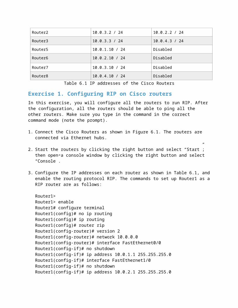
Cisco Routers Ethernet Interface FastEthernet 0/0
Ethernet Interface FastEthernet 1/0
Router1 10.0.1.1 / 24 10.0.2.1 / 24
Router2 10.0.3.2 / 24 10.0.2.2 / 24
Router3 10.0.3.3 / 24 10.0.4.3 / 24
Router5 10.0.1.10 / 24 Disabled
Router6 10.0.2.10 / 24 Disabled
Router7 10.0.3.10 / 24 Disabled
Router8 10.0.4.10 / 24 Disabled
Table 6.1 IP addresses of the Cisco Routers
Exercise 1. Configuring RIP on Cisco routersIn this exercise, you will configure all the routers to run RIP. After the configuration, all the routers should be able to ping all the other routers. Make sure you type in the command in the correct command mode (note the prompt).
1. Connect the Cisco Routers as shown in Figure 6.1. The routers are connected via Ethernet hubs.
2. Start the routers by clicking the right button and select “Start”; then open a console window by clicking the right button and select “Console”.
3. Configure the IP addresses on each router as shown in Table 6.1, and enable the routing protocol RIP. The commands to set up Router1 as a RIP router are as follows:
Router1>Router1> enableRouter1# configure terminalRouter1(config)# no ip routingRouter1(config)# ip routingRouter1(config)# router ripRouter1(config-router)# version 2Router1(config-router)# network 10.0.0.0Router1(config-router)# interface FastEthernet0/0Router1(config-if)# no shutdownRouter1(config-if)# ip address 10.0.1.1 255.255.255.0Router1(config-if)# interface FastEthernet1/0Router1(config-if)# no shutdownRouter1(config-if)# ip address 10.0.2.1 255.255.255.0Router1(config-if)# endRouter1# clear ip route *Router1#
Note:The command no ip routing is used to reset all previous configurations related to routing (RIP, OSPF, etc.) The command clear ip route * deletes all entries in the routing table. Make sure that all static routing entries are removed, since, by default, RIP does not overwrite static routing entries in IOS.
4. From each router, issue a ping command to the IP address of interfaces FastEthernet0/0 and FastEthernet1/0 on all remote routers. For example to issue a ping from Router1 to interface FastEthernet0/0 on Router2, type
Router1# ping 10.0.3.2
Your topology is correctly setup once you can successfully ping the connected interfaces of all routers.
5. Now check the routing table at each router by typing
Router1# show ip route
Routers 1 - 3 should have four entries in the routing table: two entries for directly connected networks and two other entries for remote networks that were added by RIP. Routers 5 - 8 should have four entries in the routing table: one entriy for directly connected network and three other entries for remote networks that were added by RIP.
Save the routing tables of Routers 5 - 8.
6. Stop the routers.
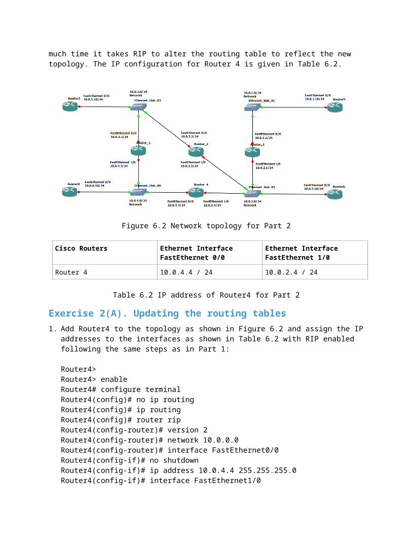
PART 2. RECONFIGURING THE TOPOLOGY IN RIPIn this part you will add Router4 to the topology as shown in Figure 6.2.
You will observe how the routing tables reorganize themselves after this change in the topology. Also you will measure approximately how much time it takes RIP to alter the routing table to reflect the new topology. The IP configuration for Router 4 is given in Table 6.2.
Figure 6.2 Network topology for Part 2
Cisco Routers Ethernet Interface FastEthernet 0/0
Ethernet Interface FastEthernet 1/0
Router 4 10.0.4.4 / 24 10.0.2.4 / 24
Table 6.2 IP address of Router4 for Part 2
Exercise 2(A). Updating the routing tables1. Add Router4 to the topology as shown in Figure 6.2 and assign the IP addresses to the
interfaces as shown in Table 6.2 with RIP enabled following the same steps as in Part 1:
Router4>Router4> enableRouter4# configure terminalRouter4(config)# no ip routingRouter4(config)# ip routingRouter4(config)# router ripRouter4(config-router)# version 2Router4(config-router)# network 10.0.0.0Router4(config-router)# interface FastEthernet0/0Router4(config-if)# no shutdownRouter4(config-if)# ip address 10.0.4.4 255.255.255.0Router4(config-if)# interface FastEthernet1/0Router4(config-if)# no shutdownRouter4(config-if)# ip address 10.0.2.4 255.255.255.0Router4(config-if)# endRouter4# clear ip route *
2. Start the routers.
3. Issue a ping from each router to every other router to check your configuration.
4. Display the route from Router5 to Router8 with the trace command and save the result.
Router5# trace 10.0.4.10
5. Run Wireshark on all links and capture the RIP packets (set a capture or display filter). Note that each router’s interface is sending out RIP packets.
a) What is the destination IP address of RIP packetsb) Do routers forward RIP packets? In other words, does Router5 receive RIP packets
sent by Router3?c) Which types of routing RIP messages do you observe? The type of RIP message is
indicated by the value of the field command in the RIP header. For each packet type that you observed, explain the role that this message type plays in the RIP protocol.
d) A RIP message may contain multiple routing table entries. How many bytes are consumed in a RIP message for each routing table entry? Which information is transmitted for each message?
6. Use the command show ip route on Routers 5 - 8 to observe how the routing tables changed from Part 1. Save the routing tables.
a) Compare the routing tables to those you saved in Part 1. How did they change?
Exercise 2(B). Convergence of RIP after a link failureIn this exercise you disconnect the Ethernet cable of interface Ethernet0/0 on Router 4 and observe how much time RIP takes to update the routing table of the Routers and PCs to reflect the new topology.
1. Issue a ping command from Router 8 to Router 5.
2. To disconnect the Ethernet cable (remove a link) connected to interface FastEthernet0/0 on Router4 in GNS3, you need to shutdown the interface. Removing the link itself will not work. Now, the output of ping on Router8 should show that the destination network is unreachable.
3. Wait until the ping command is successful again, that is, ICMP Echo Reply messages arrive at Router8. This occurs once an alternate path has been found between Router8 to Router5 and the routing tables have been updated accordingly. This may take several minutes.
4. Stop the ping command and save the ping statistics output (i.e, the data that appears at the bottom of the terminal screen when you stop the ping process).
• Count the number of lost packets and calculate the time it took RIP to update the routing tables. (The ping command issues an ICMP Echo Request message approximately once every second.)
5. Stop the routers.
PART 3. COUNT-TO-INFINITY PROBLEM IN RIP1
Distance vector routing protocols, such as RIP, are susceptible to a convergence problem known as the count-to-infinity problem. This problem is a consequence of the fact that distance vector routing protocols exchange routing information only with their neighbors. Here, it may happen that, after the failure of a link, information about routes that use the failed link are propagated a long time after the failure has occurred. This results in a slow convergence of the routing tables. Each time the router exchange RIP packets, the cost of a path that uses the failed link increases, but it takes a long time until all routers realize that reputes through the failed link are unavailable.
The goal of this part of the lab is to observe the count-to-infinity problem. RIP has a number of protocol features that try to avoid the count-to-infinity problem. These fetters will be disabled. Still, since the count-to-infinity problem requires that routing updates occur in a certain order, the count-to-infinity problem is not always observable.
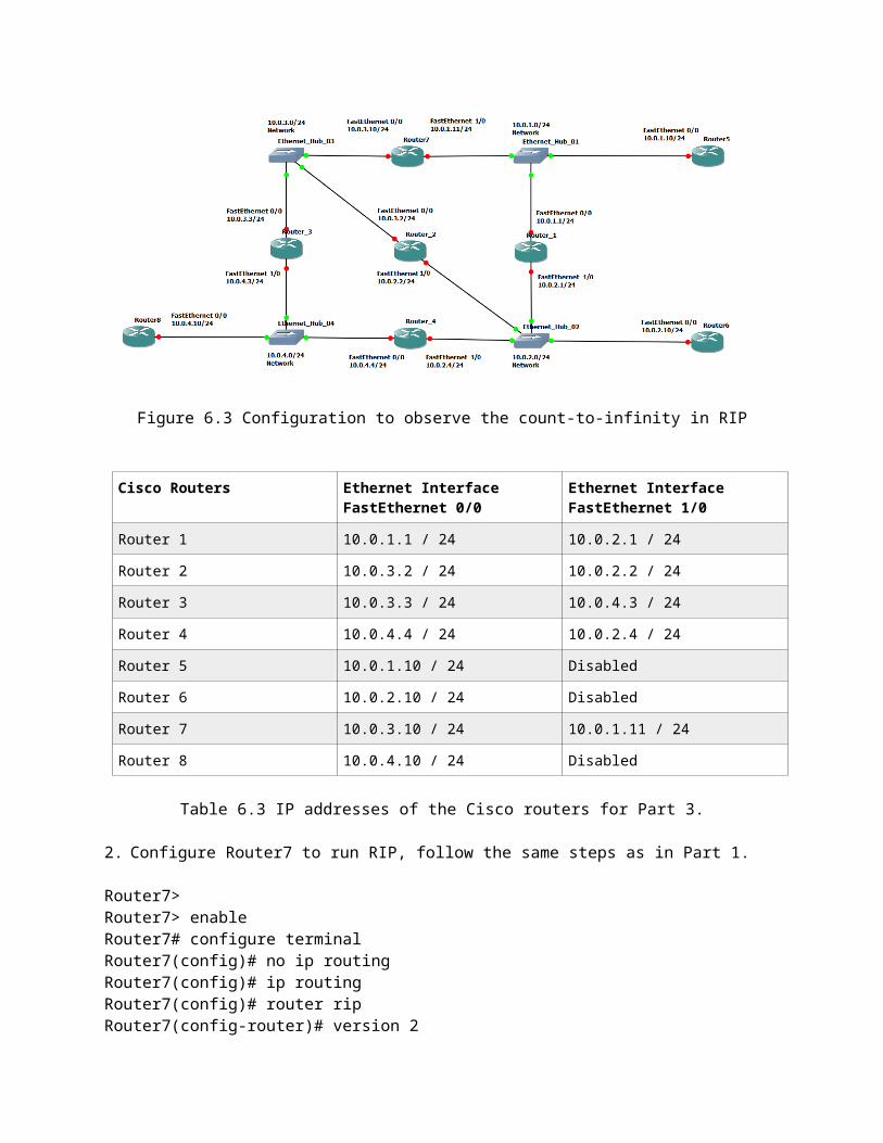
The network configuration is shown in Figure 6.3. Different from the network in Figure 6.2, Router7 is set up as an active RIP router between two hubs.
Exercise 3(A). Changing network configurationIn this exercise you will disconnect Router7 and reconnect as show in Fig. 6.3 below and once more configure as a RIP router. The steps to configure Router7 are the same as in Part1 except Router7 now has FastEthernet1/0 active.
1. Connect the interface FastEthernet1/0 of Router7 with an Ethernet cable to network 10.01.0 as shown in Figure 6.3. Assign an IP address to interface FastEthernet1/0 of Router7 as indicated in Table 6.3.
Figure 6.3 Configuration to observe the count-to-infinity in RIP
1 Not required, hard to observe.
Cisco Routers Ethernet Interface FastEthernet 0/0
Ethernet Interface FastEthernet 1/0
Router 1 10.0.1.1 / 24 10.0.2.1 / 24
Router 2 10.0.3.2 / 24 10.0.2.2 / 24
Router 3 10.0.3.3 / 24 10.0.4.3 / 24
Router 4 10.0.4.4 / 24 10.0.2.4 / 24
Router 5 10.0.1.10 / 24 Disabled
Router 6 10.0.2.10 / 24 Disabled
Router 7 10.0.3.10 / 24 10.0.1.11 / 24
Router 8 10.0.4.10 / 24 Disabled
Table 6.3 IP addresses of the Cisco routers for Part 3.
2. Configure Router7 to run RIP, follow the same steps as in Part 1.
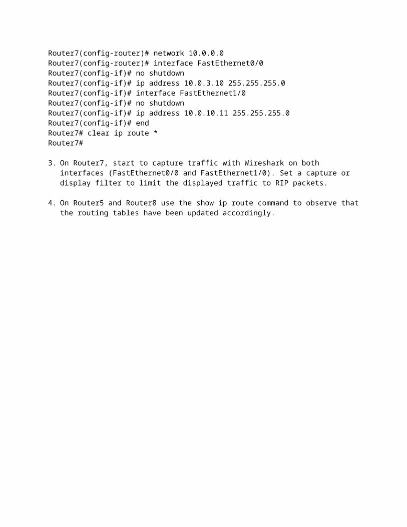
Router7>Router7> enableRouter7# configure terminalRouter7(config)# no ip routingRouter7(config)# ip routingRouter7(config)# router ripRouter7(config-router)# version 2Router7(config-router)# network 10.0.0.0Router7(config-router)# interface FastEthernet0/0Router7(config-if)# no shutdownRouter7(config-if)# ip address 10.0.3.10 255.255.255.0Router7(config-if)# interface FastEthernet1/0Router7(config-if)# no shutdownRouter7(config-if)# ip address 10.0.10.11 255.255.255.0Router7(config-if)# endRouter7# clear ip route *Router7#
3. On Router7, start to capture traffic with Wireshark on both interfaces (FastEthernet0/0 and FastEthernet1/0). Set a capture or display filter to limit the displayed traffic to RIP packets.
4. On Router5 and Router8 use the show ip route command to observe that the routing tables have been updated accordingly.
Exercise 3(B). The count-to-infinity problemThe goal of this exercise is to observe the effects of the count-to-infinity problem for routes to network 10.0.1.0/24. Note that in Figure 6.3, the traffic to network 10.0.1.0/24 passes through either Router7 or Router1. To conduct this exercise, you first ensure that traffic to network 10.0.1.0/24 always prefers the path through Router7. This is done by setting the link metric of the interface of Router1’s network 10.0.1.0/24 to a large value. Then you disable the FastEthernet1/0 interface of Router7. When the interface is disabled, the next update packet from Router7 will list the cost metric for network 10.0.1.0/24 as 16, which, in RIP, is interpreted as infinity. If this information is not distributed quickly, then the other routers in the network send RIP packets that assume that Router7 is still connected to network 10.0.1.0/24. For example, Router3 may still believe that it can reach network 10.0.1.0/24 in two hops. When such an update arrives at Router7, Router7 wrongly assumes that it can reach network 10.0.1.0/24 via Router3 in three hops. In this situation, it may take the hosts and routes a very long time before they realize that the best path to network 10.0.1.0/24 is through Router1. This slow convergence of the routing tales is the count-to-infinity problem.
RIP has several protocol feats that try to avoid the count-to-infinity problem. One of them, called triggered updates, forces a router to immediately issue a RIP update packet whenever the cost metric of a routing table entry changes. In the previous scenario, the link failure triggers an update message, which ensures that information about the link failure of Router 7 is quickly propagated to all systems in the network. This prevents routers from continuing to advertise routes that are based on incorrect information about the network topology. Another feature that avoids count-to-infinity is the hold-down mechanisms. When a router receives information that a route is unavailable (i.e., has cost metric 16), it puts the route in a hold-down state. In this state, the router ignores routing updates that advertise a better cost metric for a certain period of time (which is given by the hold-down timer).
To increase the likelihood of the count-to-infinity problem occurring, it is necessary to disable triggered updates and to set the hold-down timer to 0. Still, it may happen that the count-to-infinity problem does not manifest itself, since the problem is dependent on the timing of RIP update messages between the routers. Repeating the exercise several times will eventually exhibit the count-to-infinity problem.
If the hold-down timer is set to h, then the RIP process ignores information about an improved route for h seconds, after a RIP update packet has been received that states that this route is not available. Setting the hold-down timer to 0 means that the RIP process immediately accepts updates to a route. The command to set the hold-down timer to 0 seconds is
Router1(config-router)# timers basic 30 180 0 240
The triggered update feature is controlled by setting the value of the flash-update-threshold timer. Suppose the timer is set to h. Then, whenever the metric of a routing table changes, the router sends a RIP update packet only if the next round of (regularly scheduled) update messages is more than h seconds away. Triggered updates are disabled by setting the flash-update-threshold timer to the same value as the update timer. Assuming that the update timer is set to the default value of 30 seconds, then the command to disable triggered updates is
Router1(config-router)# flash-update-threshold 30
1. On all Cisco routers, set the hold-down timer to 0 and disable triggered updates. The configuration for Router2 follows.
Router2> enableRouter2# configure terminalRouter2(config)# ip routingRouter2(config)# router ripRouter2(config-router)# version 2Router2(config-router)# network 10.0.0.0Router2(config-router)# timers basic 30 180 0 240Router2(config-router)# flash-update-threshold 30Router2(config-router)# endRouter2# clear ip route *
2. Next, you make routes to and from network 10.0.1.0/24 through Router1 unattractive by increasing the cost metric of interfaces FastEthernet0/0 and FastEthernet1/0 at Router1 to 10. This simulates a situation in which the hop count from Router 1 to network 10.0.1.0/24 is 10 hops.
Router1# configure terminalRouter1(config)# router ripRouter1(config-router)# offset-list 0 out 10 FastEthernet0/0Router1(config-router)# offset-list 0 out 10 FastEthernet1/0Router1(config-router)# endRouter1# clear ip route *
3. Wait until the routing tables on all routers have converged. Since the cost of the interface on Router1 is set high, you should observe that the traffic from all hosts and routers to network 10.0.1.0/24 passes through Router7. This can be verified by issuing a trace to IP address 10.0.1.10.
4. Start to capture traffic with Wireshark on interface FastEthernet0/0 of Router 7. Set a display filter to display only RIP packets.
5. Issue a ping command from Router6 to Router5:
6. On Router3, enable the debugging mode of RIP. In this mode, the router displays all received RIP packets. This mode is enabled by typing:
Router3# debug ip rip
7. On Router7, disable (shutdown) interface FastEthernet1/0 to break the connection between Router7 and network 10.0.1.0. Router7 will send out a RIP packet indicating that the cost metric to network 10.0.1.0/24 is now infinity (16). When the interface is disabled, the pings from Router6 to Router5 will fail. The ping commands to Router5 are again successful, once the routing tables have converged.
8. You should observe the slow convergence of the routing tables due to the count-to-infinity problem, by observing the content of the RIP messages that are shown by Wireshark on Router7 and by observing the debugging output on Router3.
9. Save the debug messages on Router3. Disable RIP debugging on Router3 usung the command.
Router3# no debug ip rip
10. Save the RIP packets captured by Wireshark on Router7. You need to save only the packets you need to explain the count-to-infinity problem.
a) Use the saved RIP packets from Router3 and Router7 to describe the count-to-infinity problem in the preceding exercise. Include relevant fields from the saved RIP packets to illustrate your description.
Exercise 3(C). Avoiding the count-to-infinity problem.This exercise repeats Exercise 3(B), with the difference that triggered updates are enabled and the hold-down timer is set up a nonzero value. As a result, you observe that the count-to-infinity problem does not occur.
1. On Router1, enable triggered updates by setting the flash-update-threshold timer to 0, and by setting the hold-down timer to twice the value of the update timer. You can use the command show ip protocols to display the value of the update timer. If the update timer is set to the default value of 30 seconds, set the hold-down timer to 60 seconds. This is done with the following commands:
Router1# configure terminalRouter1(config)# router ripRouter1(config-router)# timers basic 30 180 60 240Router1(config-router)# flash-update-threshold 0Router1(config-router)# end
2. Repeat the previous commands on all Routers (Routers 2 - 8).
3. Now repeat Steps 3-10 from Exercise 3(B). You should observe that the count-to-infinity problem does not occur. In other words, if the connection between Router7 interface FastEthernet1/0 and network 10.0.1.0/24 is broken, you should observe that the routing tables converge much faster. Save the Wireshark output on Router7.
a) Use the output that you saved to show the differences between the outcomes of Exercise 3(B) and 3(C) with regard to the convergence of RIP.

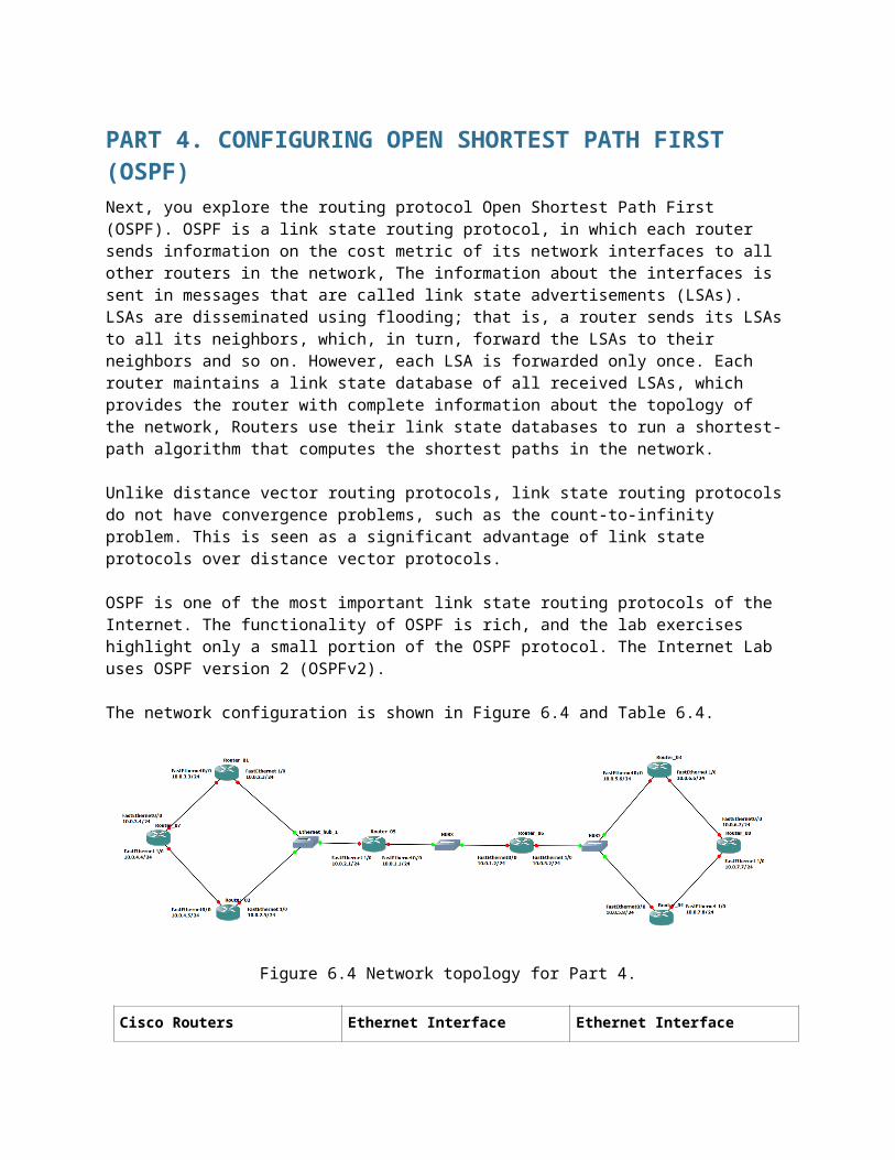
PART 4. CONFIGURING OPEN SHORTEST PATH FIRST (OSPF)Next, you explore the routing protocol Open Shortest Path First (OSPF). OSPF is a link state routing protocol, in which each router sends information on the cost metric of its network interfaces to all other routers in the network, The information about the interfaces is sent in messages that are called link state advertisements (LSAs). LSAs are disseminated using flooding; that is, a router sends its LSAs to all its neighbors, which, in turn, forward the LSAs to their neighbors and so on. However, each LSA is forwarded only once. Each router maintains a link state database of all received LSAs, which provides the router with complete information about the topology of the network, Routers use their link state databases to run a shortest-path algorithm that computes the shortest paths in the network.
Unlike distance vector routing protocols, link state routing protocols do not have convergence problems, such as the count-to-infinity problem. This is seen as a significant advantage of link state protocols over distance vector protocols.
OSPF is one of the most important link state routing protocols of the Internet. The functionality of OSPF is rich, and the lab exercises highlight only a small portion of the OSPF protocol. The Internet Lab uses OSPF version 2 (OSPFv2).
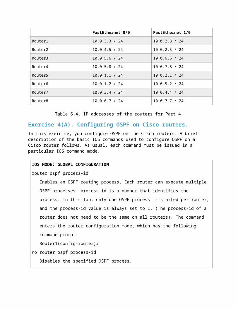
The network configuration is shown in Figure 6.4 and Table 6.4.
Figure 6.4 Network topology for Part 4.
Cisco Routers Ethernet Interface FastEthernet 0/0
Ethernet Interface FastEthernet 1/0
Router1 10.0.3.3 / 24 10.0.2.3 / 24
Router2 10.0.4.5 / 24 10.0.2.5 / 24
Router3 10.0.5.6 / 24 10.0.6.6 / 24
Router4 10.0.5.8 / 24 10.0.7.8 / 24
Router5 10.0.1.1 / 24 10.0.2.1 / 24
Router6 10.0.1.2 / 24 10.0.5.2 / 24
Router7 10.0.3.4 / 24 10.0.4.4 / 24
Router8 10.0.6.7 / 24 10.0.7.7 / 24
Table 6.4. IP addresses of the routers for Part 4.
Exercise 4(A). Configuring OSPF on Cisco routers.In this exercise, you configure OSPF on the Cisco routers. A brief description of the basic IOS commands used to configure OSPF on a Cisco router follows. As usual, each command must be issued in a particular IOS command mode.
IOS MODE: GLOBAL CONFIGURATIONrouter ospf process-id
Enables an OSPF routing process. Each router can execute multiple OSPF processes.
process-id is a number that identifies the process. In this lab, only one OSPF process is
started per router, and the process-id value is always set to 1. (The process-id of a router
does not need to be the same on all routers). The command enters the router
configuration mode, which has the following command prompt:
Router1(config-router)#
no router ospf process-id
Disables the specified OSPF process.
IOS MODE: PREVILEGED EXECshow ip ospf
Displays general information about the OSPF configuration
show ip ospf database
Displays the link state database.
show ip ospf border-routers
Displays the Area Border Router (ABR) and Autonomous System Boundary Router
(ASBR).
clear ip ospf process-id process
Resets the specified OSPF process.
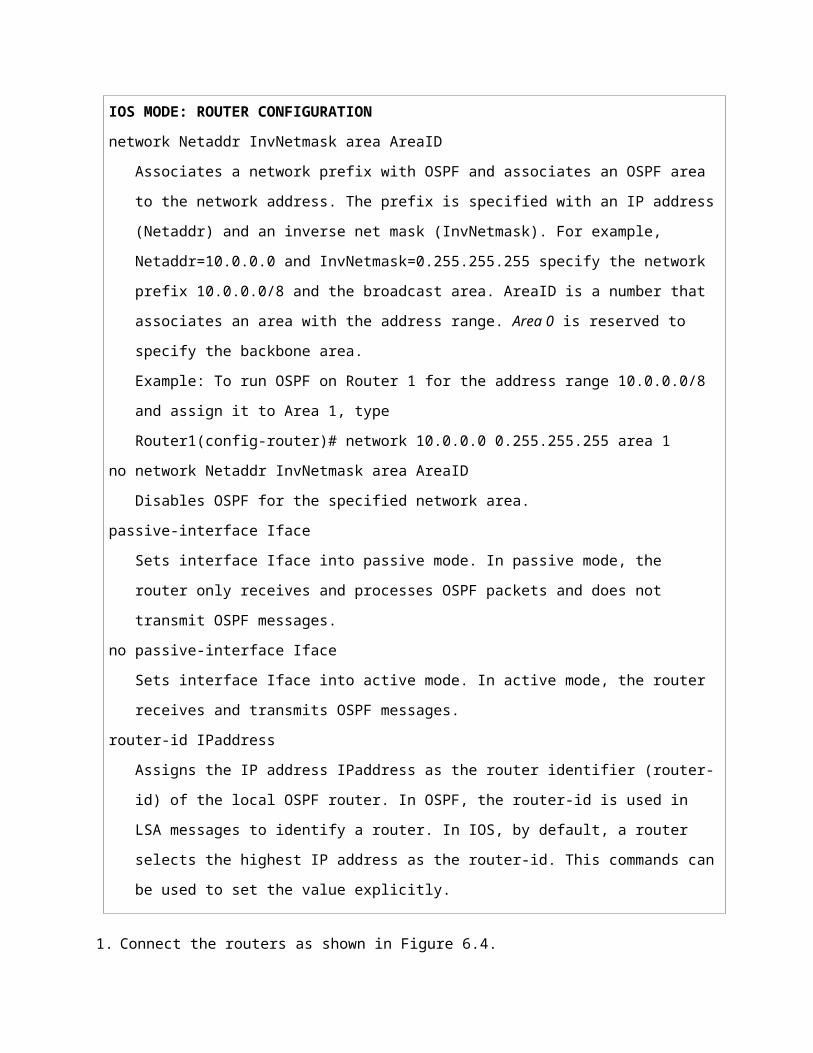
IOS MODE: ROUTER CONFIGURATIONnetwork Netaddr InvNetmask area AreaID

Associates a network prefix with OSPF and associates an OSPF area to the network
address. The prefix is specified with an IP address (Netaddr) and an inverse net mask
(InvNetmask). For example, Netaddr=10.0.0.0 and InvNetmask=0.255.255.255 specify the
network prefix 10.0.0.0/8 and the broadcast area. AreaID is a number that associates an
area with the address range. Area 0 is reserved to specify the backbone area.
Example: To run OSPF on Router 1 for the address range 10.0.0.0/8 and assign it to Area
1, type
Router1(config-router)# network 10.0.0.0 0.255.255.255 area 1
no network Netaddr InvNetmask area AreaID
Disables OSPF for the specified network area.
passive-interface Iface
Sets interface Iface into passive mode. In passive mode, the router only receives and
processes OSPF packets and does not transmit OSPF messages.
no passive-interface Iface
Sets interface Iface into active mode. In active mode, the router receives and transmits
OSPF messages.
router-id IPaddress
Assigns the IP address IPaddress as the router identifier (router-id) of the local OSPF
router. In OSPF, the router-id is used in LSA messages to identify a router. In IOS, by
default, a router selects the highest IP address as the router-id. This commands can be
used to set the value explicitly.
1. Connect the routers as shown in Figure 6.4.
2. Configure the Cisco routers to run OSPF. The following commands are used to configure Router1:
Router1> enableRouter1# configure terminalRouter1(config)# no ip routingRouter1(config)# ip routing Router1(config)# no router ripRouter1(config)# router ospf 1Router1(config-router)# network 10.0.0.0 0.255.255.255 area 1Router1(config-router)# interface FastEthernet0/0Router1(config-if)# no shutdownRouter1(config-if)# ip address 10.0.3.3 255.255.255.0Router1(config-if)# endRouter1# clear ip route *
These commands disable RIP, enable OSPF for Area 1 and network 10.0.0.0/8, and configure the IP addresses of the routers. Since no router-id is specified, the highest IP address of Router1, 10.0.3.3, is used as the router-id. The router-id can be verified by issuing the command show ip OSPF.
3. Repeat the configuration on the other routers. Refer to Figure 6.4 for the connections and to Table 6.4 for the IP addresses.
Exercise 4(B). Observing convergence of OSPF.In comparison to the distance vector protocol RIP, the link state routing protocol OSPF quickly adapts to changes in the network topology. In this exercise, you observe the interactions of OSPF after a change to the network topology.
1. On Router5, start to capture traffic with Wireshark on interface FastEthernet0/0. Set a filter to display only OSPF packets.
2. From Router7, run a trace command to Router8. Confirm from the output and Figure 6.4 whether the path from Router7 to Router8 includes Router3 or Router4.
3. Issue a ping command from Router7 to Router8 (10.0.7.7). Do not terminate the ping command until this exercise is completed.
4. If the path from Router7 to IP address 10.0.7.7 from Step 2 included Router3, then disconnect the Ethernet cable of FastEthernet1/0 interface of Router3. Otherwise, disconnect the Ethernet cable of FastEthernet1/0 interface of Router4.
When the Ethernet cable is disconnected, the ping command on Router7 will show that IP address 10.0.7.7 is not reachable.
5. Now OSPF updates the routing tables. Use the Wireshark window on Router5 to observe the transmitted OSPF messages:
• How quickly are OSPF messages sent after the cable is disconnected?• How many OSPF messages are sent?• Which type of OSPF packet is used for flooding link state information?• Describe the flooding of LSAs to all routers.• Which type of encapsulation is used for OSPF packets (TCP, UDP, or other)?• What is the destination address of OSPF packets?
6. Wait until the ping command is successful again, that is, ICMP Echo Reply messages arrive at Router7. This happens when the routing tables have been updated.
7. Stop the ping command and save the ping statics output.
• Count the number of lost packets and calculate the time it took OSPF to update the routing tables. (The ping command issues an ICMP Echo Request message approximately once every second.)
8. Issue another trace command from Router7 to IP address 10.0.7.7 By now, the output should show the new route to Router8.
9. On each router show the link state database with the command “show ip OSPF database”.
Save the output of the link state databases on all the routers.
• Can you confirm that the link state databases are identical?
10. Stop Wireshark on Router5 and save the different types of OSPF packets captured by Wireshark. Save one copy of each type of OSPF packet that you observed.
Pick a single link state advertisement packet captured by Wireshark, and describe how to interpret the information contained in the link state advertisement.
11. Stop the routers.
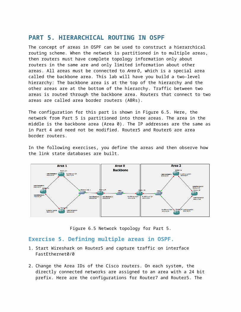
PART 5. HIERARCHICAL ROUTING IN OSPFThe concept of areas in OSPF can be used to construct a hierarchical routing scheme. When the network is partitioned in to multiple areas, then routers must have complete topology information only about routers in the same are and only limited information about other areas. All areas must be connected to Area 0, which is a special area called the backbone area. This lab will have you build a two-level hierarchy: The backbone area is at the top of the hierarchy and the other areas are at the bottom of the hierarchy. Traffic between two areas is routed through the backbone area. Routers that connect to two areas are called area border routers (ABRs).
The configuration for this part is shown in Figure 6.5. Here, the network from Part 5 is partitioned into three areas. The area in the middle is the backbone area (Area 0). The IP addresses are the same as in Part 4 and need not be modified. Router5 and Router6 are area border routers.
In the following exercises, you define the areas and then observe how the link state databases are built.
Figure 6.5 Network topology for Part 5.
Exercise 5. Defining multiple areas in OSPF.1. Start Wireshark on Router5 and capture traffic on interface FastEthernet0/0
2. Change the Area IDs of the Cisco routers. On each system, the directly connected networks are assigned to an area with a 24 bit prefix. Here are the configurations for Router7 and Router5. The other configurations are similar.
Router7, which belongs to only one area, is configured as follows:
Router7> enableRouter7# configure terminalRouter7(config)# no router ospf 1Router7(config)# router ospf 1Router7(config-router)# network 10.0.3.0/24 area 1Router7(config-router)# network 10.0.4.0/24 area 1Router7(config-router)# end

Router7# clear ip ospf 1 process
Router5 belongs to two areas and is configured as follows:
Router5> enableRouter5# configure terminalRouter5(config)# no router ospf 1Router5(config)# router ospf 1Router5(config-router)# network 10.0.2.0/24 area 1Router5(config-router)# network 10.0.1.0/24 area 0Router5(config-router)# endRouter5# clear ip ospf 1 process
3. Start Wireshark on Router5 and capture traffic on interface FastEthernet0/0.
4. Once the routing tables have converged, test the network configuration with the commands trace and ping on all routers. All routers should be able to communicate with one another.
5. Save the link state databases on all routers.
• Compare the link state databases to those saved in Part 4. What differences do you note?
• What information do routers in Area 1 have about Area 2? What information do they have about the backbone area (Area 0)?
• How much information do the routers in the backbone area (Area 0) have about the topology of Area 1 and Area 2?
• How do the routers in Area 1 know how to forward traffic to Area 2?
6. Display the area routers known to Router1 from Area 1, with the command
Router1# show ip ospf border-routers
Explain the output of the command show ip ospf border-routers.
7. From the Wireshark output of OSPF packet types, note the packet types that you did not see in Part 4.a)
PART 6. CONFIGURING THE BORDER GATEWAY PROTOCOL (BGP)The last part of this lab provides some exposure to the inter domain Border Gateway Protocol (BGP), which determines paths between autonomous systems on the Internet. The exercises in this lab cover only the basics of BGP. Essentially, you learn how to set up an autonomous system and observe BGP traffic between autonomous systems. BGP uses a path vector algorithm, where routers exchange full path information of a route. An important feature of BGP is that it can define routing policies, which can be used by a network to specify which type of traffic it is willing to process. The current version of BGP, which is also used in the following exercise, is BGP version 4 (BGP-4)
The network configuration for this part is shown in Figure 6.6, and the IP configuration information is given in table 6.5. the network has three autonomous systems with AS numbers 100, 200 and 300. One PC, PC4, is used to capture the BGP packets transmitted between the ASs.
Figure 6.6 Network topology for Part 6.
PC Ethernet Interface eth0 Default Gateway
PC1 10.0.1.10 / 24 10.0.1.1
PC2 10.0.2.10 / 24 10.0.2.2
PC3 10.0.3.10 / 24 10.0.3.3
PC4 10.0.4.10 / 24
Cisco Routers Ethernet Interface FastEthernet 0/0
Ethernet Interface FastEthernet 1/0
Router1 10.0.1.1 / 24 10.0.4.1 / 24
Router2 10.0.2.2 / 24 10.0.4.2 / 24
Router3 10.0.3.3 / 24 10.0.4.3 / 24
Table 6.5 IP addresses of the routers and PCs for Part 6.
Exercise 6(A). Basic BGP configuration.In this exercise you will configure the Cisco routers as BGP routers and assign routers to autonomous systems. The configuration is completed when you can issue ping commands between any two PCs. Below we summarize the Cisco IOS commands that are used to enable BGP.
IOS MODE: GLOBAL CONFIGURATIONrouter bgp ASnumber
Enables the BGP routing protocol and sets the autonomous system number to ASnumber.
The command enters the router configuration mode with the following prompt:
Router1(config-router)#
no router bgp ASnumber
Disables the BGP routing process.
IOS MODE: PREVILEGED EXECshow ip bgp
Displays the BGP routing table.
show ip bgp neighbors
Displays the neighbors, also called peers, of this BGP router.
show ip bgp paths
Displays the BGP path information in the local database.
clear ip bgp *
Deletes BGP routing information
IOS MODE: ROUTER CONFIGURATIONnetwork Netaddr
network Netaddr mask netmask
Specifies a network address that will be advertised by the local BGP process. A network
mask maybe added to denote the length of the network prefix.
neighbor IPaddress remote-as ASnumber
Adds a neighbor to the BGP neighbor table. IPaddress is the IP address and ASnumber is
the AS number of the neighbor.
timers bgp keepalive holdtime
Sets the values of the keep alive and hold time timers of the BGP process. BGP routers
exchange periodic messages to confirm that the connection between the routers is
maintained. The interval between these messages is keep alive seconds (default: 60
seconds). The number of seconds that a BGP router waits for any BGP message before it
decides that a connection is down is specified by the hold time (default: 180 seconds).
1. Disable all RIP or OSPF processes that are running on the Cisco routers. Use the following commands:
Router1# no router ospf 1Router1# no router rip
2. Assign the IP addresses to Ethernet interface eth0 of each PC as indicated in Table 6.5
3. Add a default gateway to PC1, PC2, and PC3 as shown in Table 6.5.
4. Start Wireshark on PC4 and set a display filter to capture only BGP packets.
5. Configure the Cisco routers to run BGP with the autonomous system numbers shown in Figure 6.6. The routers must know the AS number of their neighbors. Following is the configuration for Router2. Router2 is in AS 200 and neighbors are AS 100 and AS 300.
Router2> enableRouter2# configure terminalRouter2(config)# no ip routingRouter2(config)# ip routingRouter2(config)# interface FastEthernet0/0Router2(config-if)# no shutdownRouter2(config-if)# ip address 10.2.2 255.255.255.0Router2(config-if)# interface FastEthernet1/0Router2(config-if)# no shutdownRouter2(config-if)# ip address 10.0.4.2 255.255.255.240Router2(config-if)# router bgp 200Router2(config-router)# neighbor 10.0.4.1 remote-as 100Router2(config-router)# neighbor 10.0.4.3 remote-as 300Router2(config-router)# network 10.0.2.0 mask 255.255.255.0Router2(config-router)# endRouter2# clear ip bgp *
6. On PC1, issue a ping command to PC3. The command succeeds when BGP has converged.
7. Once the routing tables have converged, you should see all the other AS entries in the BGP routing table. On each Cisco router, save the output of the following commands (you will need this output to compare to results from Ex 6(B):
Router1# show ip routeRouter1# show ip bgpRouter1# show ip bgp paths
8. Stop the Wireshark traffic capture on PC4 and save the BGP packets captured by Wireshark.
• Describe the different types of BGP messages that you observe in the Wireshark window on PC4.
• Notice that BGP transmits messages over TCP connections. What is a reason that BGP uses TCP to transmit its messages?
• What is the IP address of the next-hop attribute for AS 100 on Router2?• What are the BGP peers in this topology?• Which BGP message(s) contain(s) the AS-PATH information? Use a BGP message to
illustrate your answer.• Use the saved output to provide a brief explanation of how the routers find the proper
path between the autonomous systems.
Exercise 6(B). BGP convergenceIn this exercise you will disconnect one of the links between two BGP peers and observe how the BGP protocol reconfigures the paths.
1. On PC4 start Wireshark and set a display filter for BGP.
2. On all routers, change the keepalive timer to 10 seconds and the holdtime timer to 30 seconds. This speeds up the convergence time by a factor of 6 as compared to the default values. The following are the commands for Router2:
Router2# configure terminalRouter2(config)# router bgp 200Router2(config-router)# timers bgp 10 30Router2(config-router)# endRouter2# clear ip bgp *
3. Disconnect the cable of interface FastEthernet1/0 on Router1.
• From the Wireshark output, observe how the BGP routers learn that a link is down. (Hint: Look at the BGP State field)
4. On PC1, issue a ping command to PC3. The command succeeds when BGP has converged.
5. Use the command show ip BGP neighbors on Router2 and Router3 to obtain the neighbor information. Compare to previous result from Ex 6(A).
6. Save the routing tables on Router2 and Router3.
What changes do you see?
7. Stop the Wireshark traffic captured on PC4 and save the Wireshark BGP packets.
Which BGP messages indicate that there is a link problem? Use a BGP message to answer the question.