Exercise 1 Pressure Switch · their state as a function of the measured process variable. ......
16
© Festo Didactic 86000-00 1 Learn the main functions of pressure switches and how to operate the pressure switch, Model 46926. The Discussion of this exercise covers the following points: Introduction Main functions of pressure switches Industrial applications Advantages and limitations Description of the supplied pressure switch Installing the pressure switch Commissioning the pressure switch Introduction In a plant, a lot of situations require the activation or deactivation of a device if a process variable is above or below a given set point. Of course, this kind of operation can be performed by a transmitter and a controller, but the cost may be prohibitive for such a simple task. To minimize expenses, this kind of task is frequently carried out by a switch. Switches are simple devices that can change their state as a function of the measured process variable. Pressure switches are very common in the industry; they come in various types and with various functionalities. This section describes the typical functionalities of pressure switches as well as those specific to the pressure switch, Model 46926. Main functions of pressure switches As its name indicates, the main function of a pressure switch is to open or close one (or more) contact(s) depending on a pressure reading. The electrical configuration of the contact(s) may vary from switch to switch, but the working principle almost always remains the same. One of the most common configurations for the contacts of a pressure switch is the single-pole double-throw (SPDT) configuration shown in Figure 1. With this type of configuration, the connection from one set of terminals (C-NC) change over to the other set of terminals (C-NO) when the switch is actuated. Pressure Switch Exercise 1 EXERCISE OBJECTIVE DISCUSSION OUTLINE DISCUSSION Instrument symbol Pressure switch
Transcript of Exercise 1 Pressure Switch · their state as a function of the measured process variable. ......

© Festo Didactic 86000-00 1
Learn the main functions of pressure switches and how to operate the pressure switch, Model 46926.
The Discussion of this exercise covers the following points:
Introduction
Main functions of pressure switches
Industrial applications
Advantages and limitations
Description of the supplied pressure switch
Installing the pressure switch
Commissioning the pressure switch
Introduction
In a plant, a lot of situations require the activation or deactivation of a device if a process variable is above or below a given set point. Of course, this kind of operation can be performed by a transmitter and a controller, but the cost may be prohibitive for such a simple task. To minimize expenses, this kind of task is frequently carried out by a switch. Switches are simple devices that can change their state as a function of the measured process variable.
Pressure switches are very common in the industry; they come in various types and with various functionalities. This section describes the typical functionalities of pressure switches as well as those specific to the pressure switch, Model 46926.
Main functions of pressure switches
As its name indicates, the main function of a pressure switch is to open or close one (or more) contact(s) depending on a pressure reading. The electrical configuration of the contact(s) may vary from switch to switch, but the working principle almost always remains the same.
One of the most common configurations for the contacts of a pressure switch is the single-pole double-throw (SPDT) configuration shown in Figure 1. With this type of configuration, the connection from one set of terminals (C-NC) change over to the other set of terminals (C-NO) when the switch is actuated.
Pressure Switch
Exercise 1
EXERCISE OBJECTIVE
DISCUSSION OUTLINE
DISCUSSION
Instrument symbol Pressure switch

Exercise 1 – Pressure Switch Discussion
2 © Festo Didactic 86000-00
Figure 1. Single-pole double-throw contact configuration.
Some types of pressure switches also use two-circuit double-make double-break (DMDB) or double-pole double-throw (DPDT) contacts. Both configurations are shown in Figure 2.
Figure 2. DMDB and DPDT configurations.
The type of contact configuration is selected as a function of the devices that the switch must actuate. Many types of switches allow the user to reconfigure the contacts according to the requirements of the process.
Hysteresis
Whatever the configuration of the contacts, the logic of pressure switches is almost always the same. This logic usually includes a set point and a hysteresis mode. When configuring a pressure switch, the user selects a pressure, the set point (SP), at which the switch will flip the states of the NC and NO contacts. He may also set a reactivation point (RSP), also known as the switch back point, which slightly changes the behavior of the switch. Figure 3 illustrates how a switch reacts when the process variable crosses the set point and the reactivation point. For the pressure switch, Model 46926, this mode is called the hysteresis function.
As shown on the upper graph of Figure 3, the switch is actuated when the pressure rises above the set point. As soon as the set point is crossed, the switch is actuated (i.e., the NO contact is set to the 1 state). When the pressure decreases and the set point is crossed again, the NO switch does not go back to the 0 state immediately. Instead, the switch remains in the 1 state as long as the reactivation set point is not crossed. This prevents the switch from switching from the 1 state to the 0 state continuously if the pressure oscillates around the set point. The states of the NO and NC contacts are shown in the lower part of Figure 3. These two contacts always have opposite states for an SPDT switch.
(a) DMDB (b) DPDT
C
NC
NO
C1
C2
NC1
NO1
NO2
NC2

Exercise 1 – Pressure Switch Discussion
© Festo Didactic 86000-00 3
Figure 3. Hysteresis function.
Window
Another type of function sometimes available on switches (such as pressure switch, Model 46926) allows monitoring if the pressure is within a range determined by the set point and the reactivation point. Figure 4 shows the states of the NO and NC contacts for a pressure curve identical to the curve of Figure 3.
SP
RSP
1
0
1
0
Time
Time
Pressure
NO contact state
NC contact state
Hysteresis zone

Exercise 1 – Pressure Switch Discussion
4 © Festo Didactic 86000-00
Figure 4. Window function.
Industrial applications
Pressure switches are found almost anywhere in the industry. They can be used to trigger alarms or as level switches. Their industrial applications are numerous and the electrical area classification of pressure switches plays an important role in the selection of a switch for a potential application. The classification of pressure switches ranges from general-purpose design to explosion-proof design. Of course, nobody wants to cause damage to a plant by selecting a general-purpose switch that is not certified for use in an environment with explosive gases, but paying extra money for a switch certified for use in a highly hazardous environment when you plan to use it only for general purposes is not wise either. For this reason, the electrical area classification of pressure switches is one of the most important factors to consider when selecting a switch for a particular application.
Advantages and limitations
The main advantages of pressure switches are that they are small, inexpensive, and relatively easy to use. On the other hand, the accuracy of most pressure switches is not very high and most of them give no or almost no feedback information other than the state(s) of the contact(s).
SP
RSP
1
0
1
0
Time
Time
Pressure
NO contact state
NC contact state
Exercise 1 – Pressure Switch Discussion
© Festo Didactic 86000-00 5
Description of the supplied pressure switch
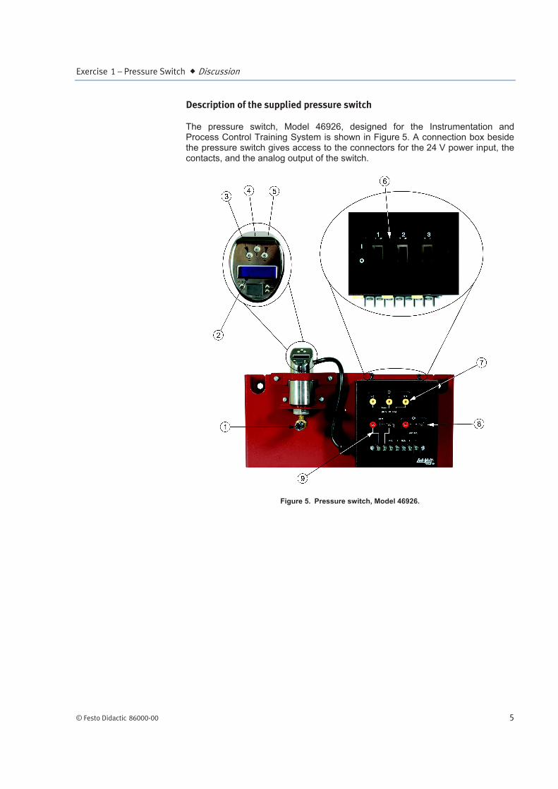
The pressure switch, Model 46926, designed for the Instrumentation and Process Control Training System is shown in Figure 5. A connection box beside the pressure switch gives access to the connectors for the 24 V power input, the contacts, and the analog output of the switch.
Figure 5. Pressure switch, Model 46926.

Exercise 1 – Pressure Switch Discussion
6 © Festo Didactic 86000-00
Table 1. Components of the pressure switch.
Component Description
Process connection Connect this port to your process to measure a pressure using the switch.
Digital display Displays the measured pressure and other information related to the operation of the pressure switch. Below the display, there is a status LED and two LEDs (S1 and S2) that give the status of the switch contacts.
– operating key Press this key to go backward in a menu or modify a value.
E operating key Press this key to select an item from a menu or store an entry. Pressing this key for at least 3 seconds gives access to or exits the operating menu.
+ operating key Press this key to go forward in a menu or modify a value.
Fault panel Contains three switches used to simulate faults with the apparatus.
Contacts connectors The connectors for the NC and NO contacts of the first switch of the device (S1).
Analog output Sends a 4-20 mA signal proportional to the measured pressure.
24 V dc input Power input for the switch. Used to energize the pressure switch with a 24 V dc signal.
Summary of technical specifications
Some technical specifications are summarized in this section. For details, please refer to the documentation provided with the system.
Device name Ceraphant T (PTC31)
Measured variables Pressure
Power supply 24 V dc
Measuring range 0 kPa to 1000 kPa (0 psi to 145 psi)
Pressure accuracy ±0.5%
Operating temperature of the sensor -40°C to 85°C (-40°F to 185°F)
Temperature of the process -40°C to 100°C (-40°F to 212°F)
Installing the pressure switch
Like other types of pressure detection devices, pressure switches may read the pressure inaccurately if the impulse line connecting the switch to the process is not filled correctly. For this reason, be sure to fill the impulse line with the process fluid. This is especially important if the process fluid is a liquid. This is the case if you measure the pressure at the bottom of the column of the Instrumentation and Process Control Training System.
In an industrial context, be careful to follow the manufacturer’s instructions when installing a pressure switch. The type of installation for pressure switches usually depends on whether it is connected to a liquid, steam, or gas process.
Exercise 1 – Pressure Switch Discussion
© Festo Didactic 86000-00 7
Commissioning the pressure switch
The pressure switch is powered using a 24 V dc source. The status LED turns green if the switch operates normally. A red status LED indicates an error, while a status LED blinking from red to green indicates a warning. Refer to Appendix C for a list of the error and warning codes.
The pressure switch can be configured using the three operation keys (+, –, and E). These keys can be pressed using the tip of a pen. To avoid damaging the operation keys, be sure not to use too sharp or too pointed an object to press them.
Menu structure of the pressure switch
To access the operating menu of the pressure switch, press the E key for at least 3 seconds. After three seconds, the first function group of the menu is displayed (i.e., Base). Use the + and – keys to navigate through the function groups and press the E key to select a function group. Table 2 gives the structure of the operating menu. The Procedure section details how to configure the pressure switch for use with the Instrumentation and Process Control Training System. For a complete description of the functions of the pressure switch, refer to Appendix B.

Exercise 1 – Pressure Switch Procedure Outline
8 © Festo Didactic 86000-00
Table 2. Operating menu structure.
Function group
Function Parameters
BASE
E
UNIT + BAR + PSI + K/MPA + %
-/+
ZERO + 0.0
GET.Z + 0.0
DISP + PV + PVRO + SP + SPRO + OFF + OFFR
TAU + 0.0
DESI + NO + YES
SAFC + NO + YES
SAFR + O
OUT
E
FUNC + HYNO + WINC + HYNC + WINO
-/+
SP + 0.0
RSP + 0.0
TSP + 0.0
TRSP + 0.0
OUT2
E
FNC2 + HYNO + WINC + HYNC + WINO + 4-20
-/+
SP2 + 0.0
RSP2 + 0.0
TSP2 + 0.0
TRSP + 0.0
4-20
E
SETL + 0.0
-/+
SETU + 0.0
GETL + 0.0
GETU + 0.0
FCUR + MIN + MAX + HOLD
SERV
E
LOCK + 0
-/+
CODE + 0
PRES + NO + YES
REV’C + 0
LST’A + 0
SIM + OFF + OPEN
SIM2 + OFF + OPEN
MAX’ + 0.0
MIN’ + 0.0
The Procedure is divided into the following sections:
Setup and connections
Commissioning the pressure switch
Setup and connections
1. Connect the equipment according to the piping and instrumentation diagram (P&ID) shown in Figure 6 and use Figure 7 to position the
PROCEDURE OUTLINE
PROCEDURE

Exercise 1 – Pressure Switch Procedure
© Festo Didactic 86000-00 9
equipment correctly on the frame of the training system. To set up your system for this exercise, start with the basic setup presented in the Familiarization with the Instrumentation and Process Control Training System manual and add the equipment listed in Table 3.
Table 3. Material to add to the basic setup for this exercise.
Name Model Identification
Pressure switch 46926 PIS 1
Electrical unit 46970
Pneumatic unit 46971
Color Paperless Recorder 46972 UR 1
Accessories 46993
Figure 6. P&ID.

Exercise 1 – Pressure Switch Procedure
10 © Festo Didactic 86000-00
Figure 7. Setup.
2. In this exercise, the pressure switch is used to measure the air pressure at the top of the column. Therefore, be sure that the impulse line connecting the switch to the top of the column is free of water.
3. Connect the control valve to the pneumatic unit. Details about the installation and operation of the control valve are available in the Familiarization with the Instrumentation and Process Control Training System manual.
4. Connect the pneumatic unit to a dry-air source with an output pressure of at least 700 kPa (100 psi).
Air from the pneumatic unit(140 kPa (20 psi))
Exercise 1 – Pressure Switch Procedure
© Festo Didactic 86000-00 11
5. Wire the emergency push-button so that you can cut power in case of emergency. The Familiarization with the Instrumentation and Process Control Training System manual covers the security issues related to the use of electricity with the system as well as the wiring of the emergency push-button.
6. Do not power up the instrumentation workstation yet. Do not turn the electrical panel on before your instructor has validated your setup—that is, not before step 11.
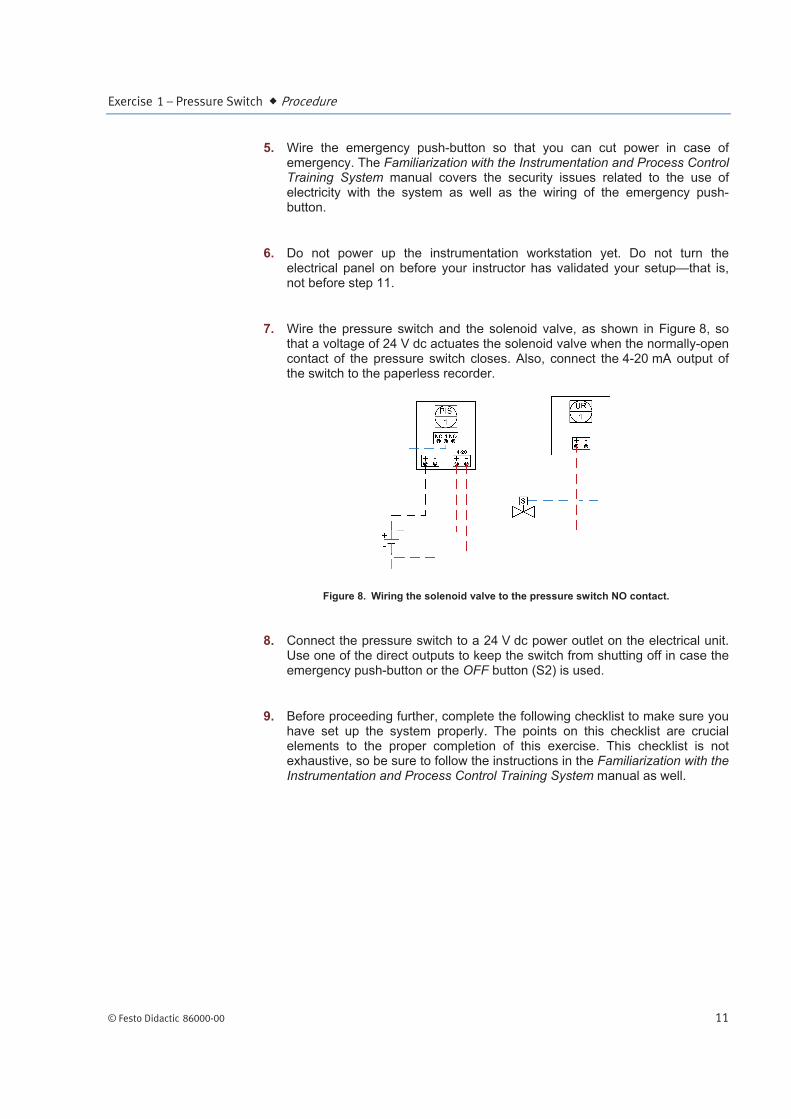
7. Wire the pressure switch and the solenoid valve, as shown in Figure 8, so that a voltage of 24 V dc actuates the solenoid valve when the normally-open contact of the pressure switch closes. Also, connect the 4-20 mA output of the switch to the paperless recorder.
Figure 8. Wiring the solenoid valve to the pressure switch NO contact.
8. Connect the pressure switch to a 24 V dc power outlet on the electrical unit. Use one of the direct outputs to keep the switch from shutting off in case the emergency push-button or the OFF button (S2) is used.
9. Before proceeding further, complete the following checklist to make sure you have set up the system properly. The points on this checklist are crucial elements to the proper completion of this exercise. This checklist is not exhaustive, so be sure to follow the instructions in the Familiarization with the Instrumentation and Process Control Training System manual as well.

Exercise 1 – Pressure Switch Procedure
12 © Festo Didactic 86000-00
f
All unused male adapters on the column are capped and the flange is
properly tightened.
The ball valves are in the positions shown in the P&ID.
The three-way valve at the suction of the pump (HV1) is set so that the flow
is directed toward the pump inlet.
The control valve is fully open.
The pneumatic connections are correct.
The solenoid valve is wired so that the valve opens when the NO contact of
the pressure switch closes.
The 4-20 mA output of the pressure switch is connected to a channel of the
paperless recorder.
10. Ask your instructor to check and approve your setup.
11. Make sure it is safe to energize the system for you and for the team working on the other side of the system, if any. When ready, turn on the main power. Do not press the S1 button yet.
12. The pressure switch initializes and the display turns on after a few seconds.
Commissioning the pressure switch
This section provides the steps for resetting the pressure switch to factory defaults and to configure it for use with the Instrumentation and Process Control Training System. Once you have successfully completed this section, you should be able to configure the pressure switch yourself.
Resetting the pressure switch to factory defaults
13. Once the switch is on, it displays the actual process pressure. However, it is probably not configured for your needs. Therefore, it is recommended that you reset the device in order to start with the factory settings. To do this, start by pressing the E key for at least 3 seconds to access the operating menu.
14. From the operating menu, use the + and – keys to select the SERV function group. Press the E key to access the functions of this group.
15. Use the E key to select the PRES function and press the + key two times to set this function to YES. Press the E key to confirm.
16. Press the E key for at least 3 seconds to display the SAVE function. Press the + key onceto select YES and then press the E key to confirm and save the changes to the switch memory. The status LED flashes from green to red

Exercise 1 – Pressure Switch Procedure
© Festo Didactic 86000-00 13
and a warning W210 message, indicating that the configuration has been changed, is displayed.
17. Resetting the switch sets the 4-20 mA output as output 2. If no load, such as a multimeter or a paperless recorder, is connected to the output, the status LED turns red and an error E042 message is displayed. Connecting a load to the analog output removes this error.
a If you do not want to connect a device to the 4-20 mA output, you can jump the output using a small wire to prevent the switch from displaying error E042.
Configuring the pressure switch
18. You may already be able to navigate through the menus of the pressure switch with a relative ease. Nevertheless, the key(s) used to navigate through the menus and their actions are summarized in Table 4 au-dessous.
Table 4. Navigating through the menus of the pressure switch.
Action Key(s) to press
Access the operating menu. E (hold at least 3 seconds)
Select a function group. + or –
Select a function within a function group. E
Change the parameter(s) of a function. + or –
Exit the parameter list of a function. E
Exit a function group and return to the operating menu.
E (several times)
Exit the operating menu and display the measured value.
E (hold at least 3 seconds)
Save the changes made in the configuration.
Use + or – to select Yes at the SAVE prompt (when exiting the operating menu) and press E for at least 3 seconds to confirm.
19. In the next step, you will set the switch zero. Open HV4 so that the column is at atmospheric pressure.

Exercise 1 – Pressure Switch Procedure
14 © Festo Didactic 86000-00
20. Use Table 2, Table 4, and the keys of the pressure switch to set the parameters of the switch functions as shown in Table 5
Table 5. Pressure switch parameters.
Function group
Function Parameter Description
BASE
UNIT KPA (PSI) Sets the units for the measurement of pressure.
GET.Z 0 Sets the zero of the switch to the actual pressure reading1. Make sure the column is not pressurized when you set the zero of the pressure switch (i.e., HV4 is open).
DISP PV Displays the pressure when not in the operating menu.
TAU 1.0 s Sets the damping value for the display and the output signal to 1.0 second.
DESI NO Turns off the DESINA connection option.
OUT
FUNC HYNO Enables the hysteresis function.
SP 70 kPa (10 psi) Sets the set point.
RSP 50 kPa (7 psi) Sets the reactivation point.
TSP 0.0 s Sets the switch point delay.
TRSP 0.0 s Sets the switch-back point delay.
OUT2 FNC2 4-20 Indicates that the second output is
the 4-20 mA analog output.
4-20
SETL 0 kPa (0 psi) Sets the pressure at which OUT2 produces a minimum signal of 4 mA.
SETU 250 kPa (35 psi) Sets the pressure at which OUT2 produces a maximum signal of 20 mA.
FCUR MAX Produces a signal of 21 mA in case of an error.
Press the E key for at least 3 seconds to display the SAVE function. Press once on the + key to select YES and then press the E key for at least 3 seconds to confirm and save the changes to the switch memory.
21. Be sure the column is ready to be pressurized. That is, close HV4 and check if all caps and hoses are in place.
22. Press the S1 button to power all the devices not already active on the station (i.e., the drive, the pneumatic devices, etc.).
23. Test your system for leaks. Use the drive to make the pump run at low speed to produce a small flow rate. Gradually increase the flow rate, up to 50% of the maximum flow rate that the pumping unit can deliver (i.e., set the drive speed to 30 Hz). Repair any leaks.
24. Stop the drive and let the column drain.
1 You can add an offset manually using the ZERO function in the BASE function group.

Exercise 1 – Pressure Switch Conclusion
© Festo Didactic 86000-00 15
25. Start the pump and set the flow rate to 75% of the maximum flow rate that the pumping unit can deliver (i.e., set the drive speed to 45 Hz).
26. Watch the pressure reading on the pressure switch increase.
27. What happens when the pressure reaches 70 kPa (10 psi)?
28. Describe what happens next?
29. Stop the pump, open HV4, and turn off the power to the system.
You should now be able to configure the pressure switch, Model 46926, to measure a pressure and close the NO contact when the set point is crossed. You have also learned what hysteresis is and how to configure the pressure switch to use the hysteresis function.
1. What is the contact configuration of pressure switch, Model 46926?
2. What does the hysteresis function of the pressure switch do?
CONCLUSION
REVIEW QUESTIONS
Exercise 1 – Pressure Switch Review Questions
16 © Festo Didactic 86000-00
3. What does the window function of the pressure switch do?
4. Name one advantage of pressure switches.
5. Name one disadvantage of pressure switches.