EXECUTIVE SUMMARY - Vertical Flight SocietyDisk loading 2.58 lbs/ft2 ENGINE RATING (ISA, S.L. 103°)...
21
1 EXECUTIVE SUMMARY 29 TH ANNUAL AHS INTERNATIONAL DESIGN COMPETITION UNDERGRADUATE CATEGORY Eliya Wing Juan Pablo Afman Michael Avera Michael Burn Christopher Cofelice Peter Johnson Robert Lee Ian Moore Travis Smith Gökçin Çınar Özge Sinem Özçakmak Yakut Cansev Küçükosman
Transcript of EXECUTIVE SUMMARY - Vertical Flight SocietyDisk loading 2.58 lbs/ft2 ENGINE RATING (ISA, S.L. 103°)...
1
EXECUTIVE SUMMARY
29TH ANNUAL AHS INTERNATIONAL DESIGN
COMPETITION
UNDERGRADUATE CATEGORY
Eliya Wing
Juan Pablo Afman Michael Avera Michael Burn
Christopher Cofelice Peter Johnson
Robert Lee Ian Moore
Travis Smith Gökçin Çınar
Özge Sinem Özçakmak Yakut Cansev Küçükosman

2
CONCEPT DESIGN SUMMARY
BADGER SPECIFICATIONS
WEIGHTS Units Value
Empty Weight lbs 2148
Max. Gross Weight lbs 2800
GTOW lbs 2500
Payload lbs 300
Max. Fuel Weight lbs 127
PERFORMANCE @ S.L. 103 F Units GW 2500 lbs GW 2800 lbs
Max. Cruise Speed kts 175.9 174.2
Speed at 90% MCP kts 165.7 164.1
Best Range Speed kts 119.8 123.6
Best Endurance Speed kts 68.6 73.1
Max. Sideward Flight Speed kts 65.5 37
Max Sustained Load Factor G 3.11
Course Time s 247.8
POWER PLANT Units Value
Number of Engines 1
MRP @2 min 103°F S.L hp 550
MCP @ 103°F S.L hp 424
GENERAL DIMENSIONS Units Value
Number of Blades (per rotor) 2
Main Rotor Diameter ft 24.8
Main Rotor Blade Chord ft 0.66
Main Rotor Disk Loading lbs/ft2 2.58
Tip Speed ft/s 670
Propeller Diameter ft 6
Flat Plate Area Forward Flight ft2 7
Flat Plate Area Sideward Flight ft2 41

3
A NEW TWIST ON INTERMESHING
This ain’t your mama’s “air mule”
Fact: The Badger is no simple “air mule”.
It has been designed to be a fast and
maneuverable pylon racing helicopter
ACKNOWLEDGEMENT OF REQUIREMENTS
•M
ISC
ELLA
NEO
US
•MIS
SIO
N
•PER
FOR
MA
NC
E Max start speed <100 kts
Max bank angle of 90°
Slung load capabilities
HOGE take off @S.L. 103°F , TOGW
Cruise at min of 125 kts @90 % MCP
60 kts SW flight @ S.L 103°F, TOGW
Time Estimates
Fuel burned throughout mission
η Function
One 225 lbs pilot
10 min warm up time
5 min to takeoff
15 min fuel reserve @VBR
15 ft safety zone
Minimum clearance of one rotor radius from moving components
MIL STD 850B visibility
Floatation/Fire protection for pilot
Accounted power installation factors
Inboard/outboard profiles of helicopter
Weight allocations for all components (MIL STD 1374)
Pilot feedback
Preliminary structural design
Avionics suite meeting min FAA req. for NY VFR corridor

4
DIMENSIONS
Length Overall 25.17 ft
Overall height 12.67 ft
Fuselage width 4.33 ft
Rotor diameter 24.8 ft
Disk loading 2.58 lbs/ft2
ENGINE RATING
(ISA, S.L. 103°)
Number of Engines 1
MCP 424 hp
MRP @ 2 min 550 hp
WEIGHT
Max. TOGW 2800 lbs
Empty 2148 lbs
Max. Fuel 127 lbs
Crew 225 lbs
Slung payload 300 lbs
PERFORMANCE
TOGW@ 2500 lbs (ISA, S.L. 103°)
Best endurance speed 68.4 kts
Best range speed VBR 119.8 kts
Max. speed 175.9 kts
Speed at 90% MCP 165.7 kts
Sideward Flight Speed 65.5 kts
5
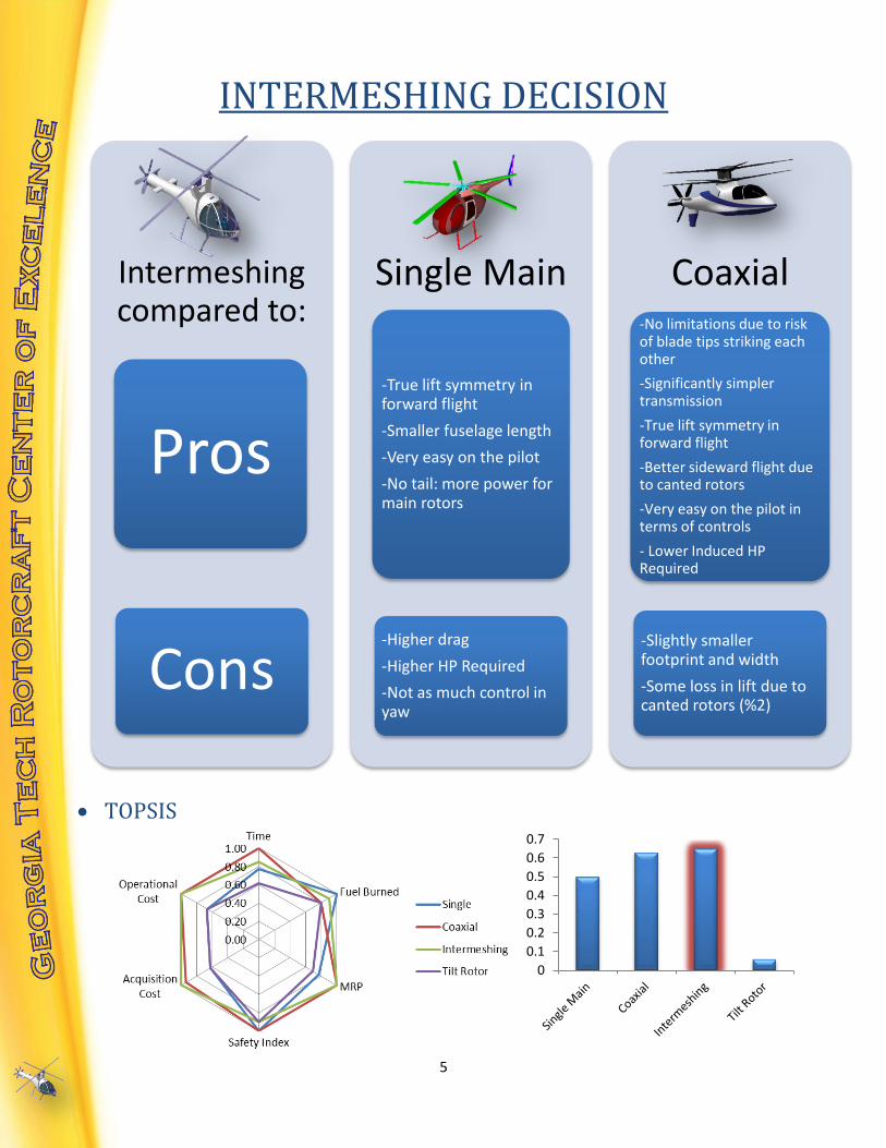
INTERMESHING DECISION
TOPSIS
Intermeshing compared to:
Pros
Cons
Single Main
-True lift symmetry in forward flight
-Smaller fuselage length
-Very easy on the pilot
-No tail: more power for main rotors
-Higher drag
-Higher HP Required
-Not as much control in yaw
Coaxial -No limitations due to risk of blade tips striking each other
-Significantly simpler transmission
-True lift symmetry in forward flight
-Better sideward flight due to canted rotors
-Very easy on the pilot in terms of controls
- Lower Induced HP Required
-Slightly smaller footprint and width
-Some loss in lift due to canted rotors (%2)
0
0.1
0.2
0.3
0.4
0.5
0.6
0.7
6
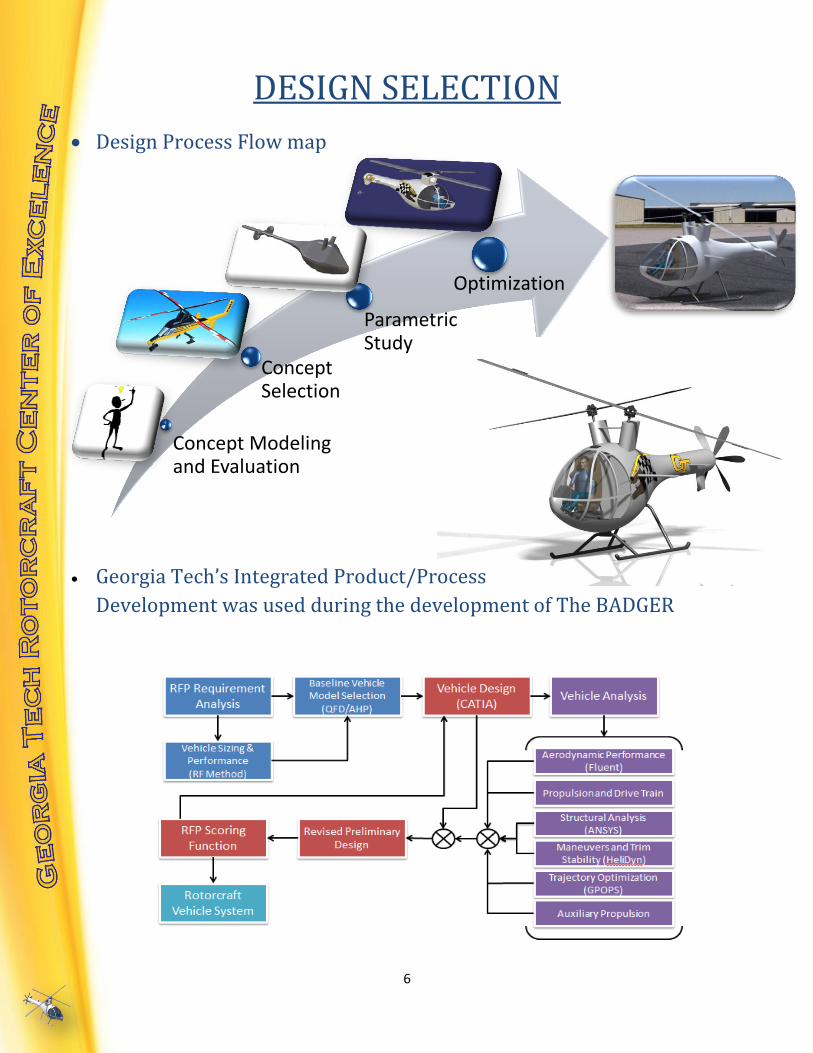
Concept Modeling and Evaluation
Concept Selection
Parametric Study
Optimization
DESIGN SELECTION
Design Process Flow map
Georgia Tech’s Integrated Product/Process
Development was used during the development of The BADGER

7
WEIGHT BREAKDOWN
Several trade studies were conducted with respect to material decisions.
The primary objective was to effectively choose technologically advanced
materials and manufacturing methods that would result in weight reduction
while keeping in mind the aircraft’s structural integrity, pilot safety and cost
effectiveness.
Main rotor blades, 176lbs
Main rotor hub, 175lbs
Empenage, 100lbs
Fuselage structure, 400lbs
Landing gear, 75lbs
Engine Nacelle, 35lbs
Engine installation, 55lbs
Engine, 141lbs
Drive system, 350lbs
Cockpit Controls, 40lbs
System Controls, 100lbs
Hydraulics, 50lbs
Electrical systems, 50lbs
Crew Weight, 225lbs
Avionics & Instruments, 150lbs
Furnishing, 25lbs
Aux Propulsion, 200lbs
Fuel system and tanks, 25lbs
Fuel Weight, 120 lbs

8
12%
10%
27%
8% 1% 1%
7%
7%
13%
14%
Fuselage
Nacelles
Main Rotor Hub
Landing Gear
Horizontal Tail
Vertical Tail
Interference
Exhaust
AuxiliaryPropellerMisc
DRAG BUILDUP
• Empirical drag build-up for forward
flight Flat Plate Area (EFPA) of 7.2 ft2
Computational Fluid Dynamics was used to determine sideward flight
Equivalent Flat Plate Area = 41 ft2. This allowed The BADGER team to
determine and overcome the thrust required to meet RFP requirement of
60kt sideward flight.
Component Parasite Drag (ft^2)
Fuselage 0.822
Nacelles 0.7263
Main Rotor Hub 1.9638
Landing Gear 0.6
Horizontal Tail 0.101
Vertical Tail 0.07
Interference 0.5
Exhaust 0.5
Auxiliary Propeller .912
Miscellaneous 1
Total Frontal 7.2

9
PERFORMANCE ANALYSIS
Successfully outperforms RFP performance
requirements with the use of auxiliary
propulsion in the form of a pusher propeller
for both increased acceleration and
deceleration properties.
Sized to a standard atmospheric temperature of 103 degrees Farenheight,
The BADGER’s performance characteristics allow it not only to perform,
but outperform the competition even in demanding weather conditions.
Parameter (103F) GW = 2500lbs GW = 2800lbs
Best range speed 119.8312 knots 123.5676 knots Best endurance speed 68.5893 knots 73.1264 knots
Maximum speed 175.8769 knots 174.2756 knots
Speed at 90% MCP 165.7353knots 164.134knots
0 50 100 150 200 2500
100
200
300
400
500
600
2500lb Gross Weight
Velocity (Knots)
Pow
er
(H
P)
MCP @ SL 103 F
90% MCP
Power Required @ SL 103 F
0 50 100 150 200 2500
100
200
300
400
500
600
2800lb Gross Weight
Velocity (Knots)
Pow
er
(H
P)
MCP @ SL 103 F
90% MCP
Power Required @ SL 103 F

10
Outstanding Lift to Drag Ratios
The BADGER is able to achieve a 4k ft/min maximum rate of climb
A plot of minimum turning radius
versus velocity was necessary to
ensure that our helicopter was
capable of performing certain
maneuvers expected in the race
such as the 300 ft 180 degree turn
in the beginning of the track.
0 50 100 150 200 250 3000
0.5
1
1.5
2
2.5
3
3.5
4Lift to Drag Ratio Vs Velocity @ 2500lbs, 80F
Velocity (Knots)
Lift
to D
rag R
atio,
L/D
0 20 40 60 80 100 120 140 160 180 2000
500
1000
1500
2000
2500
3000
3500
4000
4500
5000Maximum Rate of Climb Vs Velocity @ 2800lbs, 80F
Velocity (Knots)
Maxim
um
Rate
of
clim
b,
R/C
max (
ft/m
in)
0 20 40 60 80 100 120 140 160 180 2000
500
1000
1500
2000
2500
3000
3500
4000
4500
5000Maximum Rate of Climb Vs Velocity @ 2500lbs, 80F
Velocity (Knots)
Maxim
um
Rate
of
clim
b,
R/C
max (
ft/m
in)
0 20 40 60 80 100 120 140 160 180 2000
200
400
600
800
1000
1200
1400
1600
1800
2000
Velocity (Knots)
Min
imum
Turn
ing R
adiu
s (
ft)
0 20 40 60 80 100 120 140 160 180 2000
500
1000
1500
2000
2500
3000
3500
4000
4500
5000Maximum Rate of Climb Vs Velocity @ 2800lbs, 80F
Velocity (Knots)
Maxim
um
Rate
of
clim
b,
R/C
max (
ft/m
in)

11
CONTROLS AND HANDLING QUALITIES
Nonlinear synchropter model built in HeliDyn
Controller Design Includes: o SAS o Attitude Command Attitude
Hold o Rate Command Attitude Hold o Velocity Hold o Altitude hold
Fly by Light Architecture o Replaces mechanical linkages with electronic actuators o Reduces weight through use of fiber optic cable o Less susceptible to electromagnetic interference than fly by
wire systems o Electronic actuators allow for easy implementation of a flight
control system computer and quick response time which is crucial for a highly maneuverable and agile rotorcraft
Level 1 Handling Qualities

12
MAIN ROTOR DESIGN
Low Disk loading
o Better maneuverability
o Limited by RFP size Restrictions
High Aspect Ratio
o Decrease in Power Required
o Structural chord > .05ft
Highest tip speed possible
o Increased performance
o Increased maneuverability
o Based on VR7b airfoil data
Blade Element Momentum Theory (BEMT)
o Used to find optimum airfoil and blade twist
0.4 0.5 0.6 0.7 0.8 0.9 1 1.1 1.2 1.3400
450
500
550
600
650
700
750
800
850
900
Average Blade Chord (ft)
Vtip (
ft/s
)Tip Speed vs Average Blade Chord
N=2
N=3
Desired Chord
Desired Chord
Boundary Constraints

13
5 10 15 20 25 30 35
50
55
60
65
70
75
Effect of Mast Distance on Induced HP
Velocity (Knots)
Induced H
P
Rotor Distance=0
Rotor Distance=1ft
Rotor Distance=2ft
Rotor Distance=3ft
Rotor Distance=4ft
Rotor Distance=5ft
HUB DESIGN
Teetering hub with hub spring and
feathering bearing. Elastomeric hub
spring gives control power at <1 G
maneuvers
Servo – flap controls collective and cyclic pitch with the advantage of a
lower drag hub by removal of pitch links
Angle of mast of 13° with 1° precone angle
for max flapping angle clearance
Ideal mast separation allows Induced Horsepower to be lower than a
typical coaxial rotor configuration
0 5 10 15 20 251
1.05
1.1
1.15
1.2
1.25
1.3
1.35
1.4
1.45
Coaxial
BADGER
Single Main
X: 3
Y: 1.35
Effect on Density Changes Due to Temperature
Distance between rotors (ft)
Induced P
ow
er
Overlap C
orr
ection (
Kov)
Harris (1999)
Momentum Theory
14
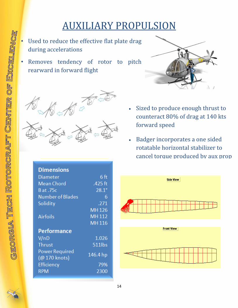
AUXILIARY PROPULSION
• Used to reduce the effective flat plate drag
during accelerations
• Removes tendency of rotor to pitch
rearward in forward flight
Sized to produce enough thrust to
counteract 80% of drag at 140 kts
forward speed
Badger incorporates a one sided
rotatable horizontal stabilizer to
cancel torque produced by aux prop

15
TRAJECTORY OPTIMIZATION
Optimal control theory combined with human-pilot based constraints
o GPOPS (General Pseudospectral OPtimal control Software)
Best time of 4 minutes and 8 seconds
TRANSMISSION DESIGN
Adequate transmission sizing was performed
-3000 -2000 -1000 0 1000 2000 3000 4000
0
1000
2000
3000
4000
5000
x-coord (ft)
y-c
oord
(ft
)
-3000 -2000 -1000 0 1000 2000 3000 4000
0
1000
2000
3000
4000
5000
x-coord (ft)
y-c
oord
(ft
)

16
ENGINE SIZING
Appropiate calibrations were performed on The BADGER’s engine to
comply with RFP regulations and requirements
SL/ISA SL/103°F 6K/95°F
HP SFC
(lb/hp*hr) HP SFC
(lb/hp*hr) HP SFC
(lb/hp*hr)
OEI 703.6 0.378 581.5 0.392 474.2 0.390
MRP 672.1 0.379 550.0 0.396 445.4 0.395
IRP 626.5 0.384 508.4 0.403 409.8 0.402
MCP 512.4 0.398 415.2 0.424 338.0 0.422
Part Power 336.0 0.448 275.0 0.490 222.7 0.486
Idle 134.1 0.706 110.0 0.824 89.2 0.816

17
STRUCTURAL AND INTERNAL LAYOUT
Lightweight aluminum airframe composed of I beams, box beams, and solid beams
Two primary bulkheads to carry crash loads and main aerodynamic loads
Nose plate used to connect bottom I beam two side box beam longerons
Advantageously placed internal systems to maintain a center of gravity along the auxillary propulsion
thrust vector
Internal systems attached to upper I beam and longerons as well as front bulkhead to optimize load paths
Load hook mounted on the bottom I beam to support 300 lb slung load
Aluminum hollow tube crashworthy landing gear
FEA landing gear and airframe test conductued using ANSYS static strucural toolbox
Crash loads approximated with a 2g load factor on landing gear supports and 4g on airframe

18
SAFETY CAPABILITIES
5 Point harness BAE S7000 crashworthy seat that
meets MIL – 58095A and MIL – STD -810 safety
requirements
Portable and compact fire extinguisher that
allows The BADGER to comply with the
requirements given by the 2012 RFP regarding
fire protection
Autorotative index of 22.5 for the
unfortunate case of an engine failure
during the race
0 2 4 6 8 10 12 14 160
20
40
60
80
100
120
140
160
180
200
Bell 206
AH-1
R22
CH-53E
AH-64
Bell 412
BADGER
Autorotative Indices for Several Helicopters
Rotor Disk Loading, DL - lb/ft2
Roto
r K
inetic E
nerg
y p
er
Unit G
ross W
eig
ht
AI = 5
AI = 10
AI = 20
Phantom 5 minute emergency oxygen tank
allowing pilot to survive underwater while
emergency personnel perform rescue mission
Small and light weight military designed
inflatable raft which allows The BADGER to
comply with the requirements given by the
2012 RFP regarding flotation for the pilot

19
COCKPIT DESIGN
High-visibility cockpit
design based on Marenco
Swisshelicopter concept.
Planes of vision meet
MILSTD-850B requirements
Dynon Skyview 7” Electronic Flight
Instrumentation System (EFIS )
Contains Primary Function Display (PFD),
Moving Map, and Engine Monitoring
Installed with “soft stop” alerting system
(EICAS) to alert pilot in event of critical engine
levels or approaching any helicopter limits
Heads-Up Display (HUD) projecting
optimized trajectory course onto windshield
for pilot aid during race
Quick release switch for cargo hook in
case of an unexpected emergency
landging is required

20
TOP TEN TRADE STUDIES
• Based off of the trade study results,
all technologies used are currently on the
market
• The Badger is a TRL of 7.5, this
places it in “The System Development
phase”
• Five Year Expected Production
COST ANALYSIS
Average production cost per helicopter: $1,689,926

21
GT – BADGER : WE’LL SEE YOU AT THE RACE LINE
The BADGER’s official η = 1380.6
All RFP requirements are 100% satisfied
The BADGER is a highly maneuverable unconventional
agile rotorcraft
Its unique intermeshing rotor configuration separates
it from conventional designs
The auxiliary propulsion system allows for incredible
acceleration and deceleration during the race