Executive Summary Phase I FDR TEXT.pdfExecutive Summary The United States Environmental Protection...
103
Transcript of Executive Summary Phase I FDR TEXT.pdfExecutive Summary The United States Environmental Protection...


Executive Summary The United States Environmental Protection Agency (EPA) issued a Superfund Record of Decision (ROD) on
February 1, 2002 (EPA, 2002a) calling for, among other things, the dredging and disposal of certain sediments
from the Upper Hudson River containing polychlorinated biphenyls, or PCBs. The remedy selected by EPA is
precedent setting in scope, and the design process has been extraordinarily complex. Plans and specifications
have been developed for the river-based activities such as dredging, backfilling/capping, and habitat
reconstruction as well as the construction and operation of the land-based sediment processing facility and
project rail yard. The dewatered sediment will be loaded into rail cars dedicated to the project, then transported
out of the Hudson River Valley for final disposal. The project was designed considering quality of life
concerns, cultural and archaeological resources, threatened and endangered species, and wetlands (in-river and
at the processing facility). Adaptive management protocols for habitat replacement and reconstruction have also
been developed.
The ROD states that dredging will occur in two distinct phases. Phase 1 is defined as the first year of dredging,
and is the focus of this report. Phase 1 also includes preparatory work, such as the construction of the land-
based sediment processing facility, as discussed below. Since an environmental dredging project of this scale
has never before been implemented in the United States, the division of the project into two phases is a critical
element of the overall design. During Phase 1, each component of the remedy will be tested to determine the
appropriateness and validity of the guiding assumptions incorporated into the design. Equipment and systems
will be operated and examined, production and processing rates will be assessed, and safety measures will be
evaluated and enhanced. In addition, water, sediments, and air will be monitored for a variety of parameters
throughout the project, and the results will be compared to the Engineering and Quality of Life Performance
Standards established by EPA.
Although considerable effort has gone into developing a remedial design capable of achieving the many goals of
the project, a number of assumptions had to be incorporated into the Phase 1 design. As a result, there is no
guarantee that these goals can be achieved at all times, either individually or in combination. At the end of
Phase 1, all the quantitative and qualitative information collected will be reviewed by EPA and the General
Electric Company (GE), and before moving into Phase 2 (which includes all subsequent years of dredging),
changes to the project, design, or performance standards may be necessary or appropriate.
BLASLAND, BOUCK & LEE, INC. engineers, scientists, economists 1

BLASLAND, BOUCK & LEE, INC. engineers, scientists, economists 2
Before dredging can begin, discussions related to finalizing plans for securing a full range of services, property,
and equipment have to be concluded. In addition, contractors will be hired to construct the land-based sediment
processing facility and rail yard in Fort Edward, as well as a marine support facility in Moreau. The areas in the
river targeted for sediment removal in Phase 1 are the northern portion of the Thompson Island Pool – a stretch
from the northern end of Rogers Island to a half mile south of Lock 7 – and an area in the vicinity of Griffin
Island.
The Phase 1 Final Design
On August 18, 2003, the GE and EPA entered into a formal agreement called the Administrative Order on
Consent for Hudson River Remedial Design and Cost Recovery (RD AOC) (Index No. CERCLA-02-2003-
2027) (EPA/GE, 2003), under which GE agreed to design the remedy outlined in the ROD. Since that time, GE
and its consultants have been developing the design for Phase 1 of the remedial action. This design also reflects
commitments contained in the Consent Decree (CD) signed by GE and EPA, which governs implementation of
the remedial action. The CD was filed in federal district court in October 2005 (EPA/GE, 2005) for the court’s
approval.
This Phase 1 Final Design Report (Phase 1 FDR) is the final step in the design of Phase 1. This report builds
upon the Preliminary Design Report (BBL, 2004a) and Phase 1 Intermediate Design Report (Phase 1 IDR)
(BBL, 2005a), both approved by EPA. The design is based on a comprehensive series of support activities,
including sediment sampling, geotechnical investigations, river bathymetry and geophysics, treatability studies,
cultural resources assessments, habitat evaluations, and baseline monitoring activities, and takes full account of
the performance standards developed by EPA.
Phase 1 of the project is designed for the dredging, dewatering, and disposal of 265,000 cubic yards (cy) of
sediment from areas of the river covering 94 acres. A series of inter-related project elements has been designed
to handle this sediment as safely and efficiently as possible. During dredging operations, targeted sediments
will be removed from the river using environmental clamshell dredging equipment, and then transported by
barge to the land-based sediment processing facility. At the processing facility, sediments will go through a
multi-stage dewatering process before being loaded into railcars for transport to a licensed landfill. After
sediment removal, dredged areas will be backfilled or capped with approximately 1 foot of clean material,
habitat replacement and reconstruction will be conducted, and disturbed shorelines will be stabilized and
restored.

BLASLAND, BOUCK & LEE, INC. engineers, scientists, economists 3
Construction of the Processing Facility and Rail Yard
A sediment processing facility and rail yard will be constructed at the 100+-acre Energy Park/Longe/New York
State Canal Corporation Site (Energy Park site) located between the Champlain Canal and Towpath Road in the
Town and Village of Fort Edward. These construction activities are expected to begin in the Fall of 2006. A
new 2-mile access road connecting the existing truck route on New York State Route 196 in the Town of
Kingsbury to the northern boundary of the site, will be built as the primary access for bringing labor, equipment,
and materials to the Energy Park site. The new access road will be built along the west bank of the Champlain
Canal and will allow access to the site without travel on Village of Fort Edward streets. A gate to the west of
Lock 8 will restrict access to the project site. The site plan, depicted on Figure 1-2 of the Phase 1 FDR, shows
the location and features of the processing facility, work support marina, site access road, and other aspects of
the project.
Site construction will include:
• Approximately 15,000 linear feet of fence and security gates;
• Approximately 20,000 linear feet of erosion control fencing;
• Approximately 90,000 cy of structural fill to be brought in to establish the necessary subgrades for the rail
yard and the stormwater collection system;
• Over 5 miles of railroad track, including onsite repair tracks, two controlled switches to the main rail line,
and inspection roads to allow for the safe staging and loading of rail cars (a switcher locomotive will be
dedicated to the project);
• Over 55,000 square yards of pavement for haul roads, parking, and work areas;
• A 41,000-square-foot, 40-foot high building to house 12 filter presses;
• A 25,000-square-foot building for a 2-million-gallon-per-day water treatment plant;
• Two lined enclosures for storage of up to 38,000 cy of processed fine sediments;
• Approximately 28,000 square feet of administrative space;
• A 1,500-foot barge unloading facility along the Champlain Canal, and a work/maintenance wharf, including
40,000 square feet of pavement;
• The widening of the Champlain Canal at the processing facility location by 65 feet; and
BLASLAND, BOUCK & LEE, INC. engineers, scientists, economists 4
• The installation of four mooring dolphins south of Lock 7 to allow for barge mooring while recreational
traffic on the river accesses the lock.
Construction, commissioning, and thorough testing of the processing facility equipment and procedures are
required before any dredged sediment can be brought to the facility.
To reduce the number of project vessels going through Lock 7, a marine staging area will be constructed on the
west shore of the river, on New York State-owned property accessible from West River Road in the Town of
Moreau. This facility will support the marine operations, and will provide parking for project personnel and
dockage for support vessels such as survey, sampling, and oversight boats. Dredged sediments will not be
transported to or processed at this marina. Large vessels (dredges, tugs, and barges) will not use this marina,
and access by the public will be restricted. This facility will include 550 feet of floating dock with
approximately 30 boat slips, administration trailers, and a parking area.
Dredging
Phase 1 dredging activities will begin in mid-May of the Phase 1 dredging season – weather and river flow
permitting – and continue into November. Approximately 265,000 cy of sediment from initial “inventory”
dredging are targeted for removal. To meet EPA’s Productivity Performance Standard, dredging is expected to
occur 24 hours a day, 6 days a week. The seventh day will be reserved for maintenance, make-up time for
unplanned project interruptions, and as a contingency to satisfy EPA’s productivity requirements.
As many as eight backhoe-mounted, hydraulically closing clamshell mechanical dredges will be used. Dredging
will begin in the northern end of the project area and will generally proceed downstream in such a way as to
maximize safety and efficiency while not unnecessarily hindering non-project navigation on the river. Dredging
in one area further south, near Griffin Island, will begin early in the program to gather valuable information on
sediment resuspension.
Sediment dredged from the river will be placed directly into one of approximately 14 barges. If there is limited
accessibility to the area being dredged, dredged sediment may be placed into a hopper and then transferred to a
barge. The barges, moved by tug boats, will transport dredged sediment and debris through Lock 7 on the
Champlain Canal, and up the canal to the unloading wharf at the processing facility. During peak operations,
there may be as many as 30 daily one-way barge trips through Lock 7, including barges that could potentially

BLASLAND, BOUCK & LEE, INC. engineers, scientists, economists 5
transport backfill to dredge areas. If barges hauling backfill come from the south, the number of daily trips
through Lock 7 will be reduced.
A computer-assisted numerical model was developed during the design process to evaluate the potential impacts
on water quality due to sediment resuspension. Based on the modeling results, controls (e.g., sheet piles, silt
curtains) are not necessary to maintain water quality standards. However, as a preventive and protective
measure, a rock dike, silt curtains, and/or steel sheet piles will be installed in the eastern channel of Rogers
Island and in an area east of Griffin Island. Control equipment (e.g., sheet piles) will also be available in two
other areas as a contingency, in the event that monitoring during project activities indicates they are necessary.
To allow limited passage of non-project vessels to and from the Fort Edward Yacht Basin, a gate will be
designed in the barrier placed at the southern end of the east channel of Rogers Island. Recreational vessels will
be able to travel through this gate each day during a ½-hour period between the hours of 7 am and 9 am, and
again during a ½-hour period between 3 pm and 5 pm. The specific ½-hour slot within these 2-hour time
periods will be determined by the dredging operations contractor.
Sediment Processing and Dewatering
The primary purpose of the sediment processing and dewatering facility is to separate river water from dredged
sediment in preparation for transport offsite. At the facility’s wharf, dredged sediment will be unloaded from
barges by either a crane or excavator, and large debris such as rocks and tree limbs or other bulky materials will
be sorted out. The remaining sediment will be processed through trommel screens and two banks of 10
hydrocyclones to sort out additional debris, gravel, and sand. This debris, gravel, and sand will be transferred
by dump truck to an onsite staging area near the rail loading area. The remaining fine sands and silt will be
mixed with polymers to enhance dewatering, and pumped through large filter presses. The “filter cake” removed
from the presses will be transferred by truck to onsite enclosed areas near the rail yard.
Water collected during the dewatering process, along with stormwater from any area at the site that might come
in contact with dredged sediment, will be collected for treatment. The onsite stormwater management system
was conservatively designed to manage a 100-year storm. The water treatment plant will be able to handle
approximately 2 million gallons of water a day. Once treated, water will be discharged to the Champlain Canal
and monitored to verify compliance with discharge limitations established by EPA.

BLASLAND, BOUCK & LEE, INC. engineers, scientists, economists 6
As with dredging, operations at the processing facility are expected to occur 24 hours a day, 6 days a week. The
seventh day will be reserved for maintenance, make-up time for unplanned interruptions, and as a contingency
to satisfy EPA’s productivity requirement.
Transportation for Disposal
Dewatered sediments will be staged in lined storage areas near the rail yard, and then loaded into lined rail cars.
A fleet of approximately 450 gondola rail cars will be procured and dedicated to the project. A switcher
locomotive will assemble 81-car unit trains and stage them on a departure track for pickup by Canadian Pacific
Railway (CPR). Multiple rail carriers will be required to transport trains to a landfill outside of the Hudson
River Valley. After unloading at the landfill, empty trains will return to the processing facility and be set by
CPR on a receiving track. On average, one full train will leave the processing facility and one empty train will
return about every 4 to 5 days. Participating rail carriers and the landfill will be identified once contract
discussions are completed.
Backfilling/Capping and Habitat Replacement and Reconstruction
After EPA and GE agree that dredging is completed in a particular area, either clean backfill will be placed, or
an engineered cap will be installed, to stabilize the sediment bed, support habitat replacement/reconstruction, or
(in the case of a cap) further isolate remaining sediments in place. Several backfill and cap configurations have
been developed, and the approach in each area will be based primarily on how fast the river flows. The type of
river bottom, residual PCB concentrations, and habitat goals will also be considered. The material used for
backfilling/capping will be acquired from local or regional quarries, and will be transported by barges and
tugboats to dredged areas. The quarries to be used will be selected by the dredging operations contractor.
After backfilling, a habitat replacement and reconstruction program will be conducted. Four different types of
habitat have been identified and mapped in the Phase 1 area. The aquatic vegetation, wetlands, and riverbank
habitats disturbed during dredging will be replaced or reconstructed. The primary goal of this program will be
to replace the functions and characteristics of impacted habitats so that they return to the range of functions and
characteristics found in similar areas of the river not impacted by dredging. Since dredging, backfilling, and
capping may not end until November, some planting activities may not occur until the following year’s planting
season. Approximately 120,000 plants, consisting of a variety of submerged aquatic and wetland species, will
be planted in dredged areas targeted for replacement/reconstruction, while other dredged areas will be allowed
to recover naturally. Details on the various habitat types and selection criteria used to determine which areas
would be planted are described in the Phase 1 Adaptive Management Plan (Attachment H of this document).
BLASLAND, BOUCK & LEE, INC. engineers, scientists, economists 7
Performance Standards
GE developed the Phase 1 Final Design to address the Engineering and Quality of Life Performance Standards
established by EPA for this project. Further, GE’s goal was to design Phase 1 of the remedy as it does all
projects: with an emphasis on worker and community safety. As a result, numerous features to prevent,
monitor, and control environmental and community impacts relative to several performance standards and other
regulatory-based requirements established by EPA were incorporated into the design.
For example, GE will implement several measures designed to mitigate levels of air emissions, odor, noise,
lighting, and navigation disruption. Modeling and other design analyses indicate that these standards can be met
for the vast majority of Phase 1 activities. One exception is the possible generation of noise above EPA’s
standard for brief periods of time at two locations along the river related to driving piles for resuspension control
structures and barge mooring dolphins. GE is continuing to evaluate this issue. Best management practices will
be followed, such as specifying that contractors use noise attenuation methods (particularly at the processing
facility), properly maintain diesel powered equipment to control noise and emissions, cover tanks and staging
areas that may be a significant source of PCB emissions to air, and control stormwater run-off and minimize
dust generation at the processing facility. For the water-based activities, specification of a project vessel
management system will reduce the potential for interference with non-project vessels, and specific procedures
are defined for communicating with mariners. Finally, a total suspended solids limit downstream of the dredge
that is much more restrictive than a corresponding provision in the EPA performance standard has been
specified. If monitoring results indicate unacceptable levels of air emissions, odor, noise, lighting, or navigation
interference, contractors will be required to implement appropriate contingency and mitigation measures to
address the source of the problem.
Monitoring Activities
To gauge the effectiveness of dredging, sediment processing, water treatment, and other aspects of the Phase 1
work relative to performance standards and water quality requirements, GE has designed an extensive
environmental monitoring program. The overall goal of the program is to provide GE and EPA with the data
and information needed to prevent conditions that could lead to an exceedance of a performance standard.
Monitoring data will also provide information on how the project is progressing, and when contingency or
mitigation actions may be warranted.

BLASLAND, BOUCK & LEE, INC. engineers, scientists, economists 8
A variety of monitoring activities will be carried out on land and on the river throughout the project, including
monitoring of water, sediments, air quality and odor, noise, lighting, and water discharged at the processing
facility. The Phase 1 Environmental Monitoring Plan (Appendix 7 of this document) and the Remedial Action
Community Health and Safety Plan (Appendix 8 of this document) provide details of all the monitoring
activities and associated contingency and mitigation plans for the performance standards and water quality
requirements.
Moving Toward Remedial Action
Much work remains before dredging can begin. First, GE will initiate a process to select contractors to perform
the Phase 1 work. GE must also conclude negotiations for a full range of services, property, and equipment. GE
will then work with the selected contractors to develop a series of Remedial Action Work Plans. In conjunction
with the Phase 1 FDR, these work plans will ultimately guide the construction and implementation of the first
phase of the Hudson River dredging project.
After these tasks are completed, construction of the processing facility and its associated rail yard will begin.
Once these facilities are built and the processing and transport systems are fully operational, the dredges, barges
and other support vessels can be mobilized to the site.

Table of Contents Section 1. Introduction ............................................................................................................... 1-1
1.1 Project Setting ................................................................................................................. 1-2 1.2 Summary of the Remedial Action Selected by EPA........................................................ 1-3 1.3 Purpose and Scope of the Phase 1 Final Design............................................................ 1-5 1.4 Description of the Phase 1 Project .................................................................................. 1-6
1.4.1 Initial Phase 1 Construction Activities ................................................................ 1-7 1.4.2 Dredging and Dredged Material Transport......................................................... 1-9 1.4.3 Resuspension Control ...................................................................................... 1-11 1.4.4 Sediment and Water Processing...................................................................... 1-12 1.4.5 Processed Sediment Transportation and Disposal .......................................... 1-14 1.4.6 Backfilling/Capping and Habitat Replacement Reconstruction ........................ 1-15
1.5 Phase 1 Final Design Report Organization ................................................................... 1-16
Section 2. Basis of Design and Supporting Information ......................................................... 2-1
2.1 Phase 1 Performance Requirements .............................................................................. 2-1 2.1.1 ROD Requirements ............................................................................................ 2-2 2.1.2 Engineering Performance Standards ................................................................. 2-3
2.1.2.1 Project-Related Resuspension ........................................................... 2-3 2.1.2.2 Dredging Residuals............................................................................. 2-4 2.1.2.3 Dredging Productivity.......................................................................... 2-4
2.1.3 Quality of Life Performance Standards .............................................................. 2-4 2.1.4 Water Quality Requirements .............................................................................. 2-5 2.1.5 Biological Assessment and Concurrence by Resource Agencies...................... 2-5
2.2 Final Design Support Activities........................................................................................ 2-7 2.2.1 Additional Treatability Studies ............................................................................ 2-8 2.2.2 Additional Year 2 Supplemental Engineering Data Collection (SEDC) Work .... 2-9 2.2.3 Additional Geotechnical Investigation Activities ............................................... 2-10 2.2.4 Habitat Delineation and Assessment (HDA) .................................................... 2-11 2.2.5 Wetland Mitigation ............................................................................................ 2-12 2.2.6 Cultural and Archaeological Resources Assessment (CARA) Update ............ 2-13
2.2.6.1 Updated Findings of Terrestrial Archaeological Survey ................... 2-14 2.2.6.2 Updated Findings of Underwater Archaeological Survey ................. 2-15
2.2.7 Permit Equivalency Analysis ............................................................................ 2-16 2.3 Final Design Analyses and Basis of Design.................................................................. 2-19
2.3.1 Design Optimization Modeling.......................................................................... 2-19 2.3.2 Dredging and Dredged Material Transport....................................................... 2-20 2.3.3 Archaeological Site Protection Measures......................................................... 2-25 2.3.4 Resuspension Control ...................................................................................... 2-26 2.3.5 Sediment and Water Processing...................................................................... 2-29
2.3.5.1 Estimated Quantities of Sediment Types.......................................... 2-29 2.3.5.2 Access Road Configuration .............................................................. 2-29 2.3.5.3 Rail Yard Site Plan............................................................................ 2-30 2.3.5.4 Slurry Force Main Sizing and Route ................................................. 2-30 2.3.5.5 Gravity Thickener Sizing and Selection ............................................ 2-31 2.3.5.6 Filter Press Sizing and Selection ...................................................... 2-31 2.3.5.7 Stormwater System Design .............................................................. 2-32 2.3.5.8 Site Work Cut and Fill Requirements................................................ 2-32
2.3.6 Processed Sediment Transportation and Disposal .......................................... 2-33 2.3.7 Backfilling/Capping and Habitat Replacement and Reconstruction................. 2-34
BLASLAND, BOUCK & LEE, INC. engineers, scientists, economists 1

BLASLAND, BOUCK & LEE, INC. engineers, scientists, economists 2
2.3.7.1 Backfilling.......................................................................................... 2-34 2.3.7.2 Capping............................................................................................. 2-35 2.3.7.3 Habitat Replacement and Reconstruction ........................................ 2-36
Section 3. Phase 1 Construction and Implementation Contract Summaries and Schedule 3-1
3.1 Phase 1 Remedial Action Contracts................................................................................ 3-2 3.1.1 Contract 1 – Facility Site Work Construction...................................................... 3-2 3.1.2 Contract 2 – Rail Yard Construction................................................................... 3-3 3.1.3 Contract 3 – Processing Facility Construction & Operations ............................. 3-4 3.1.4 Contract 4 – Dredging Operations...................................................................... 3-5 3.1.5 Contract 5 – Habitat Construction ...................................................................... 3-6 3.1.6 Contract 6 – Rail Yard Operations ..................................................................... 3-6
3.2 Phase 1 Schedule ........................................................................................................... 3-6
Section 4. Phase 1 Monitoring and Compliance with Performance Standards..................... 4-1
4.1 Phase 1 Environmental Monitoring Plan ......................................................................... 4-1 4.2 Other Compliance-Related Documents........................................................................... 4-1 4.3 Engineering Performance Standards .............................................................................. 4-2
4.3.1 Project-Related Resuspension........................................................................... 4-2 4.3.2 Dredging Residuals ............................................................................................ 4-3 4.3.3 Dredging Productivity ......................................................................................... 4-5
4.4 Design Analyses of Attaining Quality of Life Performance Standards ............................ 4-5 4.4.1 Air Quality ........................................................................................................... 4-6
4.4.1.1 PCBs in Ambient Air ........................................................................... 4-6 4.4.1.2 Opacity ................................................................................................ 4-9 4.4.1.3 NAAQS................................................................................................ 4-9
4.4.2 Odor.................................................................................................................. 4-10 4.4.3 Noise................................................................................................................. 4-11 4.4.4 Lighting ............................................................................................................. 4-16 4.4.5 Navigation......................................................................................................... 4-18
4.5 Summary ....................................................................................................................... 4-20
Section 5. References ................................................................................................................. 5-1
Section 6. Acronyms................................................................................................................... 6-1
Tables 1-1 Phase 1 FDR Organization (placed in text) 2-1 Phase 1 Inventory Dredge Schedule 2-2 Phase 1 Residual Dredge Schedule 2-3 Phase 1 Inventory Barge Schedule 2-4 Phase 1 Residual Barge Schedule 2-5 Phase 1 Backfill/Cap Schedule 2-6 Phase 1 Backfill/Cap Barge Schedule 2-7 Total Estimated Daily Vessel Traffic at Lock 7 2-8 Basis of Design for Dredging and Dredged Material Transport 2-9 Basis of Design for Resuspension Control
BLASLAND, BOUCK & LEE, INC. engineers, scientists, economists 3
2-10 Basis of Design for Sediment and Water Processing Facilities 2-11 Basis of Design for Processed Sediment Transportation and Disposal 2-12 Basis of Design for Backfilling/Capping and Habitat Restoration and Reconstruction 3-1 Phase 1 Schedule 3-2 Long Lead Equipment and Materials (placed in text) Figures 1-1 Upper Hudson River 1-2 Site Plan Overview 1-3 Phase 1 Dredge Areas 2-1 Habitat Decision Matrix Attachments A Addendum to Treatability Studies Report B Year 2 SEDC Data Summary Report C Geotechnical Investigation Summary Report D Logistics Model Summary E Dredge Prism Development / Pop-Through Analysis F Updated Resuspension Modeling Results G Water Quality Modeling Results H Phase 1 Adaptive Management Plan I Air Modeling Methodology and Results J Noise Assessment Report K CU Certification of Completion Checklist Appendices (Bound Separately) 1 Phase 1 Project Specifications and Contract Drawings for Contract 1 - Facility Site Work Construction 2 Phase 1 Project Specifications and Contract Drawings for Contract 2 - Rail Yard Construction 3 Phase 1 Project Specifications and Contract Drawings for Contract 3 - Processing Facility Construction
& Operations 4 Phase 1 Project Specifications and Contract Drawings for Contract 4 - Dredging Operations 5 Phase 1 Project Specifications and Contract Drawings for Contract 5 - Habitat Construction 6 Phase 1 Project Specifications and Contract Drawings for Contract 6 - Rail Yard Operations 7 Phase 1 Environmental Monitoring Plan 8 Remedial Action Community Health and Safety Plan
1. Introduction This Phase 1 Final Design Report (Phase 1 FDR) has been prepared on behalf of the General Electric Company
(GE) and presents the Final Design for Phase 1 of the remedy selected by the United States Environmental
Protection Agency (EPA) to address polychlorinated biphenyls (PCBs) in sediments of the Upper Hudson River,
located in New York State. This Phase 1 FDR was prepared pursuant to an Administrative Order on Consent for
Hudson River Remedial Design and Cost Recovery (RD AOC), effective August 18, 2003 (Index No.
CERCLA-02-2003-2027) (EPA/GE, 2003), consistent with the Superfund Record of Decision (ROD) issued by
EPA for the Site on February 1, 2002 (EPA 2002a). This Phase 1 FDR has been prepared in accordance with
the Remedial Design Work Plan (RD Work Plan) (Blasland, Bouck & Lee, Inc. [BBL], 2003a), and builds upon
the Preliminary Design Report (PDR) (BBL, 2004a), and the Phase 1 Intermediate Design Report (Phase 1
IDR) (BBL, 2005a), which was approved by EPA on November 1, 2005.
As set out in the RD Work Plan, the Phase 1 FDR is to take account of the information that has become
available after the Phase 1 IDR and will include the following information:
• Final Basis of Design;
• Final plans and specifications;
• Adaptive management protocols for habitat replacement and reconstruction;
• Summary of the Biological Opinions (if any) for the bald eagle and shortnose sturgeon or written
concurrence with a “not likely to adversely affect” determination in the Biological Assessment and any
related measures that EPA determines are necessary to be incorporated into the design;
• Wetland mitigation measures (if needed) related to the sediment processing/transfer facility(ies) and
associated terrestrial routes to the river; and
• Updated construction schedule.
This Phase 1 FDR also addresses EPA’s comments on the Phase 1 IDR that accompanied EPA’s November 1,
2005 approval of the Phase 1 IDR and that were assigned by EPA to be addressed in the Final Design. Other
comments were responded to in the Responses to USEPA Comments on the Phase 1 Intermediate Design Report
(GE, December 26, 2005).
BLASLAND, BOUCK & LEE, INC. engineers, scientists, economists 1-1
BLASLAND, BOUCK & LEE, INC. engineers, scientists, economists 1-2
In addition, this Phase 1 FDR was developed in a manner consistent with the following EPA guidance
documents:
• Guidance for Scoping the Remedial Design (EPA, 1995a);
• Remedial Design/Remedial Action Handbook (EPA, 1995b); and
• Guidance on EPA Oversight of Remedial Designs and Remedial Actions Performed by Potentially
Responsible Parties (EPA, 1990).
1.1 Project Setting
The Hudson River is located in eastern New York State and flows approximately 300 miles in a generally
southerly direction from its source, Lake Tear-of-the-Clouds in the Adirondack Mountains, to the Battery,
located in New York City at the tip of Manhattan Island. The ROD calls for, among other things, a remedial
action comprising the removal and disposal of PCB-contaminated sediments meeting certain mass per unit area
(MPA) and surface concentration or characteristic criteria from the Upper Hudson River (EPA, 2002a), i.e., the
section of river upstream of the Federal Dam at Troy, New York. The remedial action is to be conducted in two
distinct phases. This report addresses the design for Phase 1, which includes site development, processing
facility construction and operations, waterfront construction, rail yard construction, dredging, sediment
processing, transportation and offsite disposal of processed sediment, and habitat replacement and
reconstruction.
EPA defined three sections of the Upper Hudson River for the sediment remediation activities outlined in the
2002 ROD. The location of each river section is illustrated on Figure 1-1 and described below.
• River Section 1: Former location of Fort Edward Dam to Thompson Island Dam (TID) (from river mile
[RM] 194.8 to RM 188.5; approximately 6.3 river miles);
• River Section 2: TID to Northumberland Dam (from RM 188.5 to RM 183.4; approximately 5.1 river
miles); and
• River Section 3: Northumberland Dam to the Federal Dam at Troy (from RM 183.4 to RM 153.9;
approximately 29.5 river miles).
BLASLAND, BOUCK & LEE, INC. engineers, scientists, economists 1-3
Phase 1 of the project has been designed to occur entirely in River Section 1.
The environmental history of this site has been well documented in previous reports and is not repeated in this
introduction. This information, however, has been used in developing certain aspects of this Phase 1 design, and
the reports will be referenced in the relevant sections of this Phase 1 FDR.
1.2 Summary of the Remedial Action Selected by EPA
The remedy selected by EPA is described in the ROD. Additional descriptions of the remedial action can be
found in the PDR and RD Work Plan.
The ROD calls for the removal of sediment from the Upper Hudson River based on criteria that vary by river
section. In particular, the ROD specifies the following criteria:
• In River Section 1, sediment is to be removed based primarily on an MPA of 3 grams per square meter
(g/m2) of PCBs with three or more chlorine atoms (Tri+ PCBs) or greater;
• In River Section 2, sediment is to be removed based primarily on an MPA of 10 g/m2 Tri+ PCBs or greater;
and
• In River Section 3, sediments with concentrations of PCBs deemed high and potential for erosion deemed
high (New York State Department of Environmental Conservation [NYSDEC] Hot Spots 36, 37, and the
southern portion of 39) are to be removed.
The sediment removal criteria, including criteria based on surface sediment concentrations of Tri+ PCBs, were
further specified in EPA’s July 2004 decision in the dispute resolution proceeding on GE’s initial Phase 1
Dredge Area Delineation Report (Phase 1 DAD Report) (EPA, 2004d).
In the Feasibility Study for the Hudson River PCBs Superfund Site (FS) (EPA, 2000), using data available at the
time and using criteria discussed in the FS, EPA estimated that a total volume of 2.65 million cubic yards (cy) of
sediments would be removed from the Upper Hudson River. The ROD recognized that the actual volume to be
removed would be developed using data to be collected during remedial design. The ROD calls for the dredging
to be undertaken in two distinct phases. Phase 1, the subject of this design report, includes site development,

BLASLAND, BOUCK & LEE, INC. engineers, scientists, economists 1-4
processing facility construction, waterfront construction, rail yard construction and the first year of dredging, in
which sediment removal will be conducted at a reduced rate relative to the anticipated Phase 2 production (with
at least 1 month at full-scale production).
Since the ROD was issued in 2002, additional data and information have been collected and assessed, and the
volume of sediment targeted for removal has been refined during the remedial design process. The additional
data collection activities, conducted pursuant to the Administrative Order on Consent for Hudson River
Sediment Sampling (Sediment Sampling AOC), effective July 26, 2002 (Index No. CERCLA-02-2002-2023)
(EPA/GE, 2002), have been performed in all three river sections, including areas of the river to be addressed
during Phase 1. The data have been used to delineate dredge areas and volumes for Phase 1 dredging, as
described in the revised Phase 1 DAD Report, which was approved by EPA on March 30, 2005.
Phase 1 dredging will occur in the following areas:
• The northern portion of the Thompson Island Pool from the northern end of Rogers Island to approximately
one-half mile south of Lock 7, i.e., the area of the river between RM 194.6 and RM 193.0; and
• The area of the river in the vicinity of Griffin Island, between RM 190.4 and RM 189.9.
EPA has developed performance standards for both the engineering aspects of the project and quality of life
considerations. The Hudson River Engineering Performance Standards (Hudson EPS) cover productivity,
resuspension during dredging and other in-river activities, and concentrations of residual PCBs in surface
sediments after dredging for Phase 1 (EPA, 2004a). The Hudson River Quality of Life Performance Standards
(Hudson QoLPS) address project-related issues/impacts associated with air quality, odor, noise, lighting, and
river navigation for Phase 1 (EPA, 2004b).
An objective of the Phase 1 work is to test the effectiveness of the remedial activities relative to the performance
standards. The Hudson EPS and QoLPS are discussed as elements of the basis of design presented in Section 2
of this Phase 1 FDR. In addition, more detail on proposed methods to monitor compliance with the performance
standards during remediation activities is discussed in Section 4 and the Phase 1 Environmental Monitoring
Plan (Phase 1 EMP) appended to this Phase 1 FDR. The Phase 1 EMP is an updated version of the Remedial
Action Monitoring Scope (RA Monitoring Scope), which was included as Attachment B of Appendix B of the
Consent Decree for Hudson River Remedial Action (CD) (EPA/GE, 2005).
BLASLAND, BOUCK & LEE, INC. engineers, scientists, economists 1-5
Following submission of the Phase 1 IDR, the CD was executed by EPA and GE and lodged in the United States
District Court for the Northern District of New York. The CD includes a Statement of Work (SOW) for
Remedial Action and Operations, Maintenance and Monitoring and several attached documents that specify
requirements applicable to the design and implementation of Phase 1 of the remedial action. These documents
include the Critical Phase 1 Design Elements (CDE), the RA Monitoring Scope, the Performance Standards
Compliance Plan Scope (PSCP Scope), the Remedial Action Community Health and Safety Program Scope (RA
CHASP Scope), and the Operation, Maintenance, and Monitoring Scope (OM&M Scope). The Final Design
described in this Phase 1 FDR has been developed to be consistent with those documents.
1.3 Purpose and Scope of the Phase 1 Final Design
The primary objective of the remedial design for the Upper Hudson River is to develop plans and specifications
for implementing, in a safe and efficient manner, the EPA-selected remedy set out in the ROD, consistent with
the goal of achieving the performance standards.
Activities to accomplish the remedial design objectives are described in detail in the Phase 1 IDR, PDR and RD
Work Plan, and include the following:
• Develop remedial design deliverables to allow timely execution of the Phase 1 and Phase 2 dredging
programs;
• Collect and analyze data necessary to support the remedial design for the Upper Hudson River. This
activity has included sediment sampling, geophysical investigations, bathymetric surveys, and other tasks;
• Develop engineering and design specifications to support EPA efforts in identifying and evaluating land-
based sites necessary for project implementation, including the processing facilities;
• Design facilities to handle and process dredged sediment and prepare the sediment for transport and
disposal;
• Design a dredging program with a total target project duration of 6 years (1 year for Phase 1 and 5 years for
Phase 2), consistent with the Productivity Performance Standard provided in the Hudson EPS;
• Develop engineering and design information to support the identification and selection of the areas where
sediment will be removed during the Phase 1 dredging program;
BLASLAND, BOUCK & LEE, INC. engineers, scientists, economists 1-6
• Delineate sediment to be removed from the Upper Hudson River consistent with the criteria in the ROD, the
RD Work Plan, EPA’s decision in the Phase 1 DAD dispute resolution proceeding, and subsequent
agreements between GE and EPA;
• Develop design documents for the Phase 1 and Phase 2 dredging programs with the goal of achieving the
performance standards established by EPA;
• Develop an effective monitoring program, starting with implementation of a baseline monitoring program,
to allow an assessment of the results of remedy implementation relative to the performance standards and
remedial goals established by EPA; and
• Design the system by which: 1) the dredged and processed sediment will be efficiently and safely
transported by rail and/or barge from the processing facilities to the disposal facility(ies); and 2) the
backfill/cap material will be transported by rail and/or barge to the Upper Hudson River area prior to
placement in the river.
This Phase 1 FDR and the Phase 1 Project Specifications and Contract Drawings provide the approach for those
remedial design objectives that are applicable to Phase 1 of the project.
1.4 Description of the Phase 1 Project
This section briefly describes the Final Design of Phase 1 of the Hudson River dredging project. Each of the
primary project implementation elements is described below in a narrative format, and the goal of this section is
to provide an overall description of the Final Design for Phase 1, taking into account the additional design
analyses and basis of design completed since submittal of the Phase 1 IDR and discussed in Section 2. This
section is not intended to define the scope of work of the six Phase 1 contracts GE expects to award. The scope
of the work of each Contract is contained within the six Phase 1 Project Specifications and Contract Drawings
packages appended to this Phase 1 FDR:
• Phase 1 Project Specifications and Contract Drawings for Contract 1 – Facility Site Work Construction
(Appendix 1);
• Phase 1 Project Specifications and Contract Drawings for Contract 2 – Rail Yard Construction (Appendix
2);
BLASLAND, BOUCK & LEE, INC. engineers, scientists, economists 1-7
• Phase 1 Project Specifications and Contract Drawings for Contract 3 – Processing Facility Construction and
Operations (Appendix 3);
• Phase 1 Project Specifications and Contract Drawings for Contract 4 – Dredging Operations (Appendix 4);
• Phase 1 Project Specifications and Contract Drawings for Contract 5 – Habitat Construction (Appendix 5);
and
• Phase 1 Project Specifications and Contract Drawings for Contract 6 – Rail Yard Operations (Appendix 6).
A summary of the scope of work for each contract is provided in Section 3.
1.4.1 Initial Phase 1 Construction Activities
The initial Phase 1 construction activities will include the construction of the sediment processing facility, where
dredged sediment will be brought by barge for processing, and then loaded into rail cars and shipped to an
approved landfill outside New York State (NYS) for disposal. Based on the site selection process documented
in the Phase 1 IDR, EPA selected the Energy Park/Longe/New York State Canal Corporation (EP/L/NYSCC)
site (referred to as the Energy Park site) as the location of the proposed sediment processing facility. As shown
on Figure 1-2, the Energy Park site is situated along the shore of the Champlain Canal land cut between Locks 7
and 8.
Prior to initiation of in-river dredging, the Energy Park property must be transformed from its current condition
to a fully functional and secure sediment handling and processing facility. As discussed in Section 3.1 of this
Phase 1 FDR, the initial construction activities will include the following:
• Site Work, Roads, and Utilities – Contractors will perform initial site preparation activities including land
clearing and grubbing, installation of site perimeter security fencing and control gates, and construction of
an electrical substation to support the supply of power and the connection to primary utilities (water, sewer,
telephone). Up to 90,000 cy of select material will be brought in to the site to provide a structural sub-grade
for roads, tanks, buildings, wharfs, and rail beds. Nearly 4 miles of access and haul roadways will be built
to provide access to the site, and utilities, fences, gates, signs, and other infrastructure will be developed to
support operations. Stormwater collection and management systems will be developed to control all water
falling on all developed areas at the site, and methods to control stormwater run-on (drainage from
BLASLAND, BOUCK & LEE, INC. engineers, scientists, economists 1-8
neighboring sites) will also be constructed. Concrete paving will be installed in certain other locations, and
box culverts will be installed to allow construction of roads over Bond Creek and the Diversion Canal.
• Wharf Area Construction – A work wharf and unloading wharf along the Champlain Canal will be
constructed so that barges moored to them will be outside of the canal’s existing navigation channel. Work
will begin by performing earthwork including clearing, grubbing, and excavation. The contractor will
construct the wharves by installing pile, revetments, and rip-rap; building the structural steel superstructure
and framework; and installing the concrete deck and its rails. The unloading area will be paved with
concrete, the decontamination areas constructed, and primary utilities brought to the area.
• Processing Facility Construction – After the site work is sufficiently completed, contractors will construct
the sediment processing facility, including a coarse material separation area, a thickening and filter press
system, and water collection and treatment systems. Materials and equipment to be brought in as part of the
processing facility construction include curbing, conveyors, tanks, pumps, hydrocyclones, filter presses,
screens, piping, electrical systems, controls, clarifiers, filters, and related accessories.
• Buildings and Coverings – Initial construction activities will also include the erection of buildings and
coverings to house sediment dewatering (filter presses) and water treatment equipment to protect it from the
elements, and other processes requiring year-round operation (such as stormwater treatment) to provide
climate-controlled conditions. A maintenance shop will also be constructed in the rail yard area.
Temporary modular structures will be mobilized by contractors and set in the administration area for project
management functions, and for personal decontamination. Enclosures for processed fine sediments (filter
cake) will also be constructed to prevent addition of rainfall and to control potential volatilization of PCBs
during storage prior to loading onto rail cars.
• Processed Material Storage Area, Loadout Facilities, and Rail Yard – To facilitate efficient sequencing
and continuous loading of rail cars, processed material storage areas will be constructed alongside a rail
yard. These areas will be used to stockpile sediment material that has been separated into size classes of
debris, coarse material, and fine material. The rail yard itself will consist of approximately 31,000 feet of
track. Ballasted track and special work (e.g., crossings, other ancillary facilities and installations) will be
constructed, including the placement of ties, rail, and other track material. This work will also include the
construction of a rail maintenance building and a weigh-in-motion scale.
BLASLAND, BOUCK & LEE, INC. engineers, scientists, economists 1-9
• Material Delivery Areas – The processing facility includes a fuel depot to be used for refueling site
vehicles (trucks, loaders, excavators) during processing operations. A polymer transfer station will be
constructed in the sediment dewatering area. In addition, a rail spur will be constructed so the operations
contractor has the flexibility to use rail as a delivery means for other supplies.
• Work Support Marina Construction – The NYS property immediately north of the NYSDEC boat launch
property on West River Road will be used as a river access and support facility to reduce project marine
traffic passing through Lock 7 and at the processing facility wharf. This property will be upgraded
beginning with construction of access roads, earthwork to clear and grub the site, grading and preparation of
parking areas, and installation of trailers. Primary utilities will be brought to the site, and a dock system will
be constructed. The cultural and archeological resource and wetland assessments will be completed as part
of the acquisition process for this property. The results of these assessments may modify the layout of this
facility.
• River Mooring Installations – To facilitate barge movement, control, and staging, river moorings will be
installed near the downstream entrance of Lock 7, including one turning dolphin and four mooring dolphins.
1.4.2 Dredging and Dredged Material Transport
Upon completion of construction and testing of the processing facility and work support facility, dredging (the
first of several linked and mutually dependent project operational elements) can begin. As the initial project
operational element, the rate and process of dredging and dredged material transport affect the design and
operation of all subsequent project components.
A relatively small amount of navigational dredging will be required at the beginning of the dredging operations,
to allow sufficient depth for transport of fully loaded barges within the Champlain Canal between Locks 7 and
8.
In the Phase 1 IDR, the plan was to restrict access to the channel leading to the Fort Edward terminal wall to the
east of Rogers Island. The closure of the channel was proposed as a safety measure due to the large number of
project vessels in this area for most of Phase 1 and the presence of resuspension control barriers. After
consultation with the NYSCC during Final Design, this plan has been revised. Non-project vessels will be
allowed to travel to and from the terminal wall in Fort Edward during a ½-hour period between the hours of
BLASLAND, BOUCK & LEE, INC. engineers, scientists, economists 1-10
7:00am and 9:00 am, and again between 3:00 pm and 5:00 pm. The specific ½-hour slot in these 2-hour time
periods will be at the discretion of the dredging contractor. These windows will be reported in a Notice to
Mariners and the safe passage of recreational craft will be coordinated with the NYSCC. The gate in the
resuspension barrier will be designed to allow passage of recreational vessels.
During Phase 1, 265,000 cy of sediment have been targeted for removal in Northern Thompson Island Pool
(NTIP) and in the East Griffin Island Area (EGIA). The areas targeted for dredging cover approximately 94
acres of the river. These areas are shown on Figure 1-3, and the characteristics of each of these dredge areas are
summarized in Table 3-2 of the Phase 1 IDR. Graphical depictions of the final Phase 1 dredge areas are
presented on the dredge prisms (see Appendix 4, Drawings D-001 through D-020).
Dredging will be conducted using backhoe-mounted, hydraulically closing environmental clamshell mechanical
dredges. The selection of mechanical dredges was explained in the Phase 1 IDR. The dredging season is
planned to start in mid-May (or later if weather or river flow conditions prohibit the safe start-up of marine
operations) and continue through the end of October. Closure operations (backfilling, capping, and shoreline
restoration) may continue into November. To achieve EPA’s Productivity Performance Standard, the design is
based on up to eight dredges operating at any one time to complete the initial “inventory” dredging and any re-
dredging (the “residual” dredging) necessary in areas where PCB levels in residual sediment are not met in the
initial dredge pass. The criteria that will be used for deciding when dredging is done are described in Section
3.3.6 of the Phase 1 IDR, and operations are planned 24 hours a day, 6 days a week. The seventh day will be
reserved for maintenance, make up time for unplanned outages, or as a contingency to make up lost
productivity.
Dredging will begin in sub-area NTIP01, and work will generally proceed from upstream to downstream. The
only exception to this is that dredging in one area near East Griffin Island (EGIA01) will start approximately 2
weeks into the Phase 1 program. It is expected that valuable information about the need for and effectiveness of
resuspension controls (discussed further in Sections 1.4.3, 2.3.4, and 4.3.1 below) will be learned in EGIA01,
and this information may influence activities in other Phase 1 dredge areas. The residuals dredging – which is
any follow up dredging that may be necessary based on the residuals sampling results conducted to assess
attainment of EPA’s Residuals Performance Standard – will begin approximately 1 month after inventory
dredging, and will continue through the end of October. The ability to attain EPA’s Productivity Performance
Standard will also be evaluated during Phase 1 and the inventory dredge schedule includes the removal of
89,000 cy of inventory sediments during a 1-month period.

BLASLAND, BOUCK & LEE, INC. engineers, scientists, economists 1-11
Material dredged from the river will be placed directly into a barge, or if there is limited accessibility to the area
being dredged, the dredged material may be placed into a hopper and then pumped to a barge. The design is
based on a fleet of approximately 14 barges to transport dredged sediment and debris to the Energy Park
processing facility. Once loaded with dredged material from the river, transport barges will be moved by
tugboats and will proceed through Lock 7 to the processing facility. Barges will then be maneuvered and
moored to the wharf at the processing facility for unloading by a crane or excavator. Barge and tugboat traffic
will be monitored to optimize efficiency of the operations and to reduce impacts to other traffic on the canal.
Navigational lighting and other precautions will be used to maintain safety of the vessels, personnel, and all on-
water operations.
1.4.3 Resuspension Control
The various in-river activities that will be implemented during the Hudson River dredging project – removing
debris, dredging, backfilling, capping, moving and anchoring barges and work boats, installing/removing
resuspension controls – could resuspend sediments. Some of the fine sands, silt, and clay may remain in
suspension and move downstream, causing increases in concentrations of PCBs and/or total suspended solids
(TSS). Also, PCBs may desorb into the river when the sediment is mixed by dredging and related activities.
This Phase 1 design includes an assessment of the need for resuspension controls. Section 3.3 of the Phase 1
IDR included discussions of the various control options, the basis of the design of this element, as well as a
description of the model used to identify the activities most likely to resuspend sediments at levels that need to
be controlled, the timing of those activities, and locations where controls would be most effective. Updated
resuspension modeling results are provided in Section 2.3.4.
The modeling was performed assuming certain resuspension rates from the dredge, based on information
collected during dredging at other sites. Such data are very limited, but are the best information available to be
used in predicting the release of solids from dredging operations. Similar data are not available for other
dredging-related operations, such as debris removal, installing/removing resuspension controls, maneuvering
dredges/barges, and backfill/capping. Therefore, the model was run using a range of resuspension rates at the
dredge. Although the results indicate that no controls are necessary to comply with the Resuspension
Performance Standard, the design has included two general areas where resuspension containment will be
installed during Phase 1, either as part of contingency planning or as a test of the effectiveness of the controls:
BLASLAND, BOUCK & LEE, INC. engineers, scientists, economists 1-12
• As a contingency measure, a rock dike will be installed at the northern end of the eastern channel of Rogers
Island, and silt curtains will be installed at the southern end of Rogers Island. These control structures will
be installed during the first 2 to 4 weeks of the dredging season. The rock dike will reduce the flow of water
through this portion of the river and the silt curtain will reduce the downstream transport of resuspended
sediments, and also act to control access to this section of the river, for safety purposes.
• Due to the nature of the sediments in the area east of Griffin Island targeted for dredging during Phase 1
(EGIA01), dredging in this area is expected to provide valuable information on the effectiveness, reliability,
and operation of different resuspension control structures. Therefore, the dredge schedule in EGIA01 calls
for 2 weeks of dredging with no resuspension controls, 1 week of dredging within a sheet-piled enclosure,
and 2 weeks of dredging within an area enclosed by silt curtains.
Additional information on the design of resuspension controls is presented in Section 2.3.4 below, and Final
Design details are presented in the Phase 1 Project Specifications and Contract Drawings for Dredging
Operations, included as Appendix 4 to this Phase 1 FDR.
1.4.4 Sediment and Water Processing
This section briefly explains how dredged material travels from the river transport barges through a set of
process steps to remove water and make the sediment ready for transport by rail car for offsite disposal.
The primary objective of sediment and water processing is to effectively separate river water from sediment
solids so that the solids can be efficiently transported offsite while process water is collected, treated and
discharged to the Champlain Canal within applicable water quality requirements. Below is a brief overview of
the primary steps involved in this dewatering process as sediments are offloaded from barges, treated and
handled in controlled on-shore facilities, and then loaded onto rail cars for offsite transport (refer also to Figure
1-2 for a visual overview of the processing facilities site plan at the Energy Park site):
• Unloading at Waterfront Facilities – To keep pace with inventory and residuals dredging at a peak rate of
5,100 in situ cy per day, waterfront facilities at the Energy Park site will have the capacity to accommodate
the coming and going of up to 20 barges per day (this number does not include additional barges needed to
transport backfill and cap materials, which could add up to 10 additional barge trips per day through the
Champlain Canal if the source of these materials is north of the Energy Park site). The unloading wharf and
BLASLAND, BOUCK & LEE, INC. engineers, scientists, economists 1-13
the adjacent maintenance/staging work wharf will stretch approximately 1,500 feet along the shoreline, and
will provide direct access to the land-based sediment processing facilities. The surface of the wharf will be
sloped away from the Champlain Canal to collect runoff and help prevent material from entering the canal
during sediment unloading activities at the wharf. Also, a drip plate will be placed under the path of the
unloading bucket to cover the gap between the moored barge and the unloading wharf.
• Size Separation – At the waterfront, sediments will be separated for further processing. Debris and other
objects on the order of 2 feet in size or larger will be removed and transported to the debris storage area next
to the rail yard (all drainage water generated during debris management will be collected and treated).
Debris may be temporarily staged on the pad next to the unloading wharf.
A rotating trommel screen will be used to separate larger particles from offloaded sediment and to break up
larger clumps of sediment for further processing. Material ⅝-inch in diameter or greater will be removed
and placed in coarse solids stockpiles near the rail yard (drainage water will be captured and treated), while
smaller particles will be diverted to a sediment slurry tank capable of holding 25,000 gallons of material.
Up to 5,000 gallons per minute (gpm) of sediment slurry having a desired 25% solids content by weight will
be pumped into an array of twenty 10-inch diameter hydrocylones (including standby units) to further
separate solids into a “sand” portion and a slurry of fine sediment. The “sand” portion will be further
dewatered by vibratory dewatering screens and transported to the coarse material storage areas (drainage
water will be captured and treated). These coarse materials will be temporarily stockpiled on the pad next to
the unloading wharf before being transferred to the storage areas. Meanwhile, the remaining fine sediment
slurry will be piped to a gravity thickener near the center of the processing facility site.
• Sediment Dewatering and Thickening – The objective of this operation is to thicken the sediment slurry.
Up to 5,000 gpm of slurry will be pumped from the hydrocyclones in the separations area through nearly a
half-mile of 12-inch pipes to an 80-foot diameter gravity thickener where coagulants and flocculents
(polymers like those used in municipal wastewater treatment plants) will be added to the slurry to cause the
fine particles to bind together. As the fine particles clump together and grow heavier, they will settle into
the bottom of the gravity thickener, while the resulting clarified water is collected and treated in the onsite
water treatment facility. The settled material then will be pumped to the filter presses for dewatering.
BLASLAND, BOUCK & LEE, INC. engineers, scientists, economists 1-14
• Final Dewatering by Filter Presses – The final processing step before loading fine sediment material into
the fine material staging building is feeding the conditioned (high solids content) sediment from the
thickener through one of 12 plate-and-frame filter presses. Within the dewatering building, two rows of six
filter presses will occupy an area approximately 250 feet long and 165 feet wide. Exposed to 100 pounds
per square inch (psi) of pressure within the presses, water will be squeezed from the sediment to produce a
filter cake, with a goal of 55% solids content or higher. After inspection to determine if the filter cake is dry
enough for transport, it will be carried by truck in containers to fines storage buildings near the rail yard
where it will be placed to await shipment offsite. The materials will be subsequently loaded into lined
gondola rail cars that will be taken from the site by rail carriers for final disposal.
• Water Treatment Facility – All water from sediment processing and stormwater runoff from areas where
sediment is managed will be contained and controlled at all times. The facility is designed so that 2 million
gallons of water per day can be treated before discharge to the Champlain Canal. Multiple-stage treatment
components include flocculation tanks, clarifiers and filters to remove solids, and granular-activated carbon
(GAC) units to remove PCBs from the water. The treatment facility is designed to operate 24 hours a day, 7
days a week, and to accommodate all process flows from dewatering dredged sediment, as well as
stormwater that may be generated during weather events up to a 100-year storm. Water discharged to the
Champlain Canal will be monitored in accordance with the discharge monitoring requirements specified in
the water quality requirements (WQ requirements) provided by EPA to GE in January 2005 (EPA, 2005), as
described in the Phase 1 EMP (Appendix 7).
1.4.5 Processed Sediment Transportation and Disposal
The processed sediment transportation and disposal element of the project involves the transportation by
commercial rail carrier of processed sediment and other project waste material to a Toxic Substances Control
Act (TSCA) authorized landfill location for final disposal. The process employed to identify, evaluate and
select the mode of transportation and a short list of candidate landfills was explained in Sections 3.7 and 3.8 of
the Phase 1 IDR.
Transportation of processed sediment and other project waste material during Phase 1 will be by rail using unit
trains comprising 81 gondola rail cars (as described in the Phase 1 IDR, a unit train consists entirely of rail cars
traveling from the origin to the destination, instead of small groups of rail cars that are included in trains
carrying other commodities to different destinations). Each rail car will be weighed before leaving the site to
BLASLAND, BOUCK & LEE, INC. engineers, scientists, economists 1-15
verify that the load meets weight restrictions of the commercial carriers. Rail cars will be fitted with a
watertight liner system, a watertight lid, or a combination of both to meet applicable regulatory requirements.
The carrier serving the Energy Park site is the Delaware & Hudson Railway Company, Inc., a subsidiary of
Canadian Pacific Railway (CPR). While CPR owns and operates the rail line adjacent to the processing facility
site, and is therefore the origin carrier for purposes of the movement of project waste materials by rail, it must
“hand off” trains to an interconnected carrier for purposes of delivery to the final destination.
A fleet of approximately 450 rail cars (including an allowance for spare cars to accommodate routine and
unexpected maintenance needs) will be dedicated to the project during Phase 1. On average, one train of 81
loaded rail cars will depart from (and one train of 81 empty cars will arrive at) the rail yard at the processing
facility every 4 to 5 days during Phase 1, although once off the site, the actual frequency of train movements
will be controlled by the rail carriers.
During Phase 1, all waste materials destined for landfilling will be disposed of at a single TSCA authorized
landfill regardless of PCB concentration (this approach was referred to in the Phase 1 IDR as the “monofill”
scenario) at a location outside of NYS. Currently, GE is in final negotiations with the disposal site. The use of
a single TSCA-authorized landfill for all project waste materials eliminates the need to segregate material
according to PCB concentration at the processing facility, resulting in a more efficient design for storage,
sampling, loading and rail car management.
Upon arrival at the landfill, the cars will be unloaded, then set for the return trip to the processing facility. The
unloaded waste material will be conveyed to the active working area of the landfill, where it will be disposed of
by the landfill operator in accordance with the landfill’s operating permits and authorizations. Because the rail
cars will be dedicated and will only transport processed sediment and other project waste materials,
decontamination of the interior of the cars prior to leaving the landfill facility will not be required. Upon return
to the processing facility, rail cars will be kept in a secure area of the rail yard with restricted access prior to
their reuse. Prior to use for any other purpose (either at the end of Phase 1 or upon completion of Phase 2), rail
cars will be decontaminated in accordance with applicable regulations.
1.4.6 Backfilling/Capping and Habitat Replacement Reconstruction
Once inventory and residuals dredging are complete in a given portion of each dredge area (referred to as a
“certification unit,” or CU), the process of placing backfill or cap material can begin. The checklist that will be
BLASLAND, BOUCK & LEE, INC. engineers, scientists, economists 1-16
used to certify completion of dredging is included as Attachment K. The decision to place backfill or cap will
be based on the post-dredging distribution of PCB concentrations. There are three different types of backfill that
may be used primarily based on the surface water velocity regime for that portion of the river. Type 1 backfill
(medium sand) is designed for placement in low velocity portions of the river. Type 2 backfill (gravel) is
designed for areas of the river with moderate to high velocities. Type 3 backfill (medium sand amended with
organics) is targeted for low velocity areas where planting or recolonization of aquatic vegetation is planned to
occur. Placement of backfill of any type will not occur in the navigation channel unless the post-dredge water
depth is 15 feet or more.
For locations where a cap will be placed, several different options are available and the decision of which type
of cap is suitable for each given area is a function of the PCB concentrations that remain in the sediment after
dredging and the surface water velocities in that portion of the river. “Type A” caps will be used for situations
where the average Tri+ PCB concentration after dredging is less than or equal to 6 milligrams per kilogram
(mg/kg) and capping is necessary; and the “Type B” cap would be placed in a CU where the average Tri+ PCB
concentration is greater than 6 mg/kg after dredging. The decision to install this type of cap would be made
after GE and EPA have agreed that additional dredging is not required. There are two Type A cap designs, one
for low velocity areas and a second design for areas with moderate to high flow velocities. The Type B cap
design includes three options including low, moderate, and high velocity areas.
The replacement and reconstruction of habitat substrate will take place within a CU once dredging and
backfilling/capping operations are complete. A combination of natural re-colonization and planting has been
specified. Given the seasonality of planting, this may not be completed until the planting season following
Phase 1 dredging. The process for selection of habitats for a given area is discussed in Section 2.3.7.3 below.
1.5 Phase 1 Final Design Report Organization
This Phase 1 FDR builds upon the information presented in the PDR and Phase 1 IDR. Information in these
documents is referenced, as applicable. Design analyses that have been modified or advanced since the Phase 1
IDR are described in detail in this Phase 1 FDR.
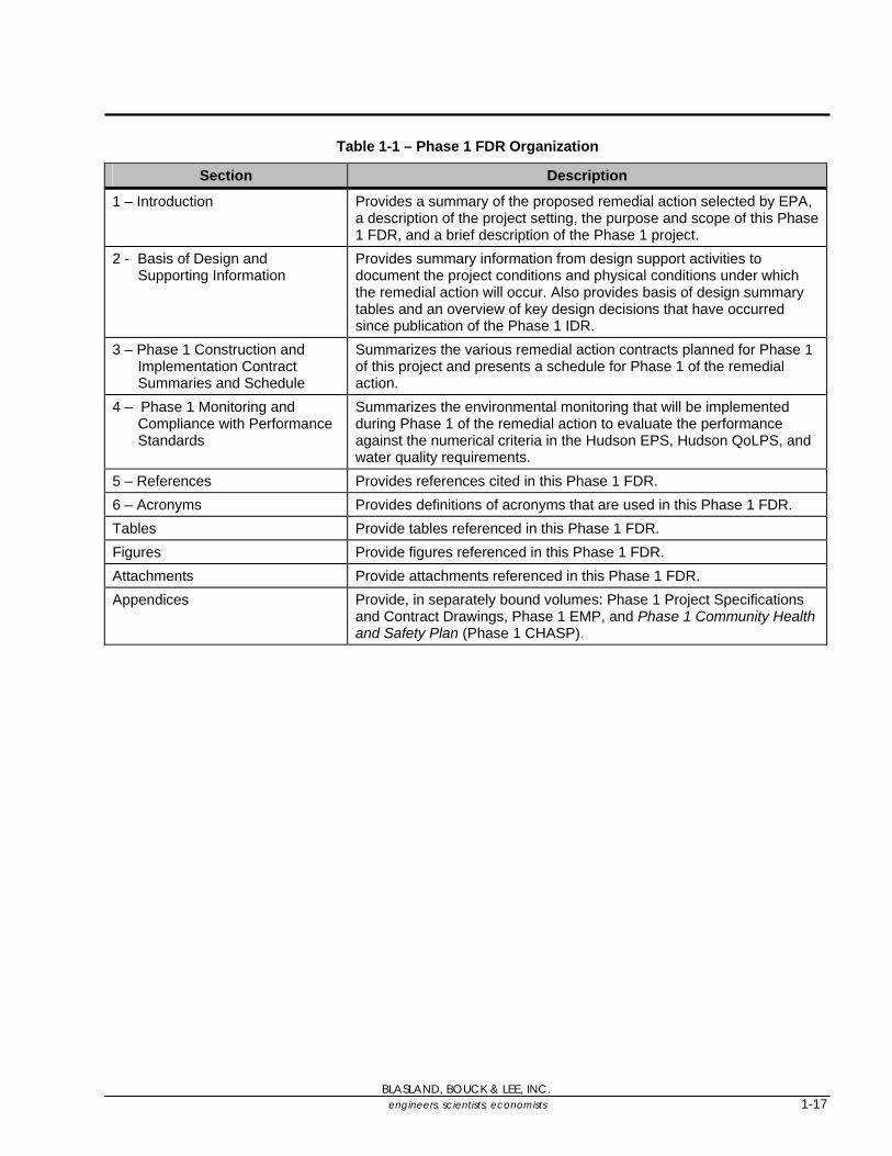
The Phase 1 FDR is organized into the sections shown in Table 1-1, below.
BLASLAND, BOUCK & LEE, INC. engineers, scientists, economists 1-17
Table 1-1 – Phase 1 FDR Organization
Section Description
1 – Introduction Provides a summary of the proposed remedial action selected by EPA, a description of the project setting, the purpose and scope of this Phase 1 FDR, and a brief description of the Phase 1 project.
2 - Basis of Design and Supporting Information
Provides summary information from design support activities to document the project conditions and physical conditions under which the remedial action will occur. Also provides basis of design summary tables and an overview of key design decisions that have occurred since publication of the Phase 1 IDR.
3 – Phase 1 Construction and Implementation Contract Summaries and Schedule
Summarizes the various remedial action contracts planned for Phase 1 of this project and presents a schedule for Phase 1 of the remedial action.
4 – Phase 1 Monitoring and Compliance with Performance Standards
Summarizes the environmental monitoring that will be implemented during Phase 1 of the remedial action to evaluate the performance against the numerical criteria in the Hudson EPS, Hudson QoLPS, and water quality requirements.
5 – References Provides references cited in this Phase 1 FDR. 6 – Acronyms Provides definitions of acronyms that are used in this Phase 1 FDR. Tables Provide tables referenced in this Phase 1 FDR. Figures Provide figures referenced in this Phase 1 FDR. Attachments Provide attachments referenced in this Phase 1 FDR. Appendices Provide, in separately bound volumes: Phase 1 Project Specifications
and Contract Drawings, Phase 1 EMP, and Phase 1 Community Health and Safety Plan (Phase 1 CHASP).
2. Basis of Design and Supporting Information This section summarizes the Phase 1 performance requirements; and the design support activities and analyses
completed since submittal of the Phase 1 IDR. The final basis of design for the Phase 1 project is presented in a
series of tables referenced in Section 2.3.
2.1 Phase 1 Performance Requirements
Performance requirements guide the design presented in this Phase 1 FDR. These requirements are derived
from the following:
• ROD (EPA, EPA, 2002a);
• Hudson EPS (EPA, 2004a);
• Hudson QoLPS (EPA, 2004b);
• Water quality requirements (WQ requirements) (EPA, 2005), which include the following: Substantive
Requirements Applicable to Releases of Constituents not Subject to Performance Standards; and Substantive
Requirements of State Pollutant Discharge Elimination System Permit for Potential Discharges to
Champlain Canal (land cut above Lock 7); and
• Hudson River PCBs Site Final Biological Assessment (Final BA) (E&E, 2006).
The Hudson EPS, the Hudson QoLPS, and the WQ requirements further develop details of the performance
requirements beyond those listed in the ROD. The actions that GE will perform to meet these requirements are
set forth in the following documents:
• Phase 1 EMP, appended to this Phase 1 FDR as Appendix 7, which is an updated version of the RA
Monitoring Scope attached to the CD, with additional details to be described in the Phase 1 Remedial Action
Monitoring Quality Assurance Project Plan (Phase 1 RAM QAPP) to be developed in accordance with the
SOW;
• PSCP Scope attached to the CD, with additional details to be specified in the Phase 1 Performance
Standards Compliance Plan (Phase 1 PSCP) to be developed in accordance with the SOW; and
BLASLAND, BOUCK & LEE, INC. engineers, scientists, economists 2-1

BLASLAND, BOUCK & LEE, INC. engineers, scientists, economists 2-2
• Phase 1 Remedial Action Community Health and Safety Plan (Phase 1 RA CHASP), appended to this Phase
1 FDR as Appendix 8, which includes the requirements specified in the RA CHASP Scope attached to the
CD.
2.1.1 ROD Requirements
The ROD sets out, in short form, the following elements of the project that have determined the Phase 1 Design:
• Removal of sediments based primarily on an MPA of 3 g/m2 Tri+ PCBs or greater from River Section 1 (all
Phase 1 areas are in River Section 1);
• Dredging of the navigation channel, as necessary, to implement the remedy and to avoid hindering canal
traffic during implementation;
• Removal of all PCB-contaminated sediments within areas targeted for remediation, with an anticipated
residual of approximately 1 mg/kg Tri+ PCBs (prior to backfilling);
• Design to achieve the Engineering and Quality of Life Performance Standards developed by EPA (discussed
below);
• Performance of the dredging in two phases whereby remedial dredging will occur at a reduced rate during
the first year of dredging (Phase 1);
• Backfill of dredged areas with approximately 1 foot of clean material to isolate residual PCB contamination
and to expedite habitat recovery, where appropriate;
• Use of rail and/or barge for transportation of clean backfill materials within the Upper Hudson River area;
• Use of environmental dredging techniques to minimize and control resuspension of sediments during
dredging;
• Transport of dredged sediments via barge or pipeline to sediment processing/transfer facilities for
dewatering and, as needed, stabilization; and
• Rail and/or barge transport of dewatered, stabilized sediments to an appropriate licensed offsite landfill(s)
for disposal.
BLASLAND, BOUCK & LEE, INC. engineers, scientists, economists 2-3
In the ROD, EPA identified as Applicable or Relevant and Appropriate Requirements (ARARs) a number of
federal and state environmental laws and regulations (see Tables 14-1 through 14-3 of the ROD). Sections 2.2.5
and 6 of the Phase 1 IDR provided more information on potentially applicable regulatory requirements. Section
2.2.7 of this Phase 1 FDR further discusses the incorporation of the substantive requirements of these potentially
applicable regulatory requirements into the Final Design documents.
2.1.2 Engineering Performance Standards
In 2003, EPA issued draft EPS for resuspension, residuals, and productivity (collectively referred to as the
Hudson EPS) for the remedy. A peer-review panel evaluated the draft standards, and the final Hudson EPS for
Phase 1 of the remedial action were issued in a five-volume report in 2004. These standards expand upon and
refine the requirements set forth in the ROD.
Specific activities that will be undertaken to address the Hudson EPS during Phase 1 are set forth in the Phase 1
EMP (appended to this Phase 1 FDR) and the PSCP Scope (attached to the CD), with additional details to be
specified in the Phase 1 RAM QAPP and Phase 1 PSCP to be developed in accordance with the SOW.
Summaries of the EPS, as they apply to the Phase 1 design, are briefly discussed in the following sections. The
analysis to assess the project’s ability to comply with the EPS is presented in Section 4.3.
2.1.2.1 Project-Related Resuspension
The Resuspension Performance Standard is a basis of design for dredging, backfilling, capping, and
resuspension controls. This standard specifies three action levels – Evaluation, Control, and Standard. These
action levels apply to PCBs and/or TSS in surface water at either near-field stations (located within 300 meters
[m] of the dredging activities) or far-field stations (located more than 1 mile downstream of dredging activities).
The Phase 1 EMP appended to this Phase 1 FDR sets out the scope of the routine monitoring, reporting
requirements, and action levels used to trigger additional monitoring during the remedial action, as well the
scope of that additional monitoring. The PSCP Scope describes the response actions that will be taken when the
resuspension action levels are exceeded (with additional details to be provided in the Phase 1 PSCP). More
details on how the Resuspension Performance Standard relates to the design, including a description of the
resuspension model used in the design analysis and the initial results, were presented in Section 2.2.2.1 of the
BLASLAND, BOUCK & LEE, INC. engineers, scientists, economists 2-4
Phase 1 IDR. Since that time, the resuspension modeling has been updated. A discussion of the updated results
is presented in Section 2.3.4.
2.1.2.2 Dredging Residuals
The Residuals Performance Standard is a component of the basis of design for dredging, backfilling, and
capping. This standard describes action levels for Tri+ PCBs in surface sediment that remains after dredging.
The action levels will be applied on a CU basis. CUs are described in Section 3.3 of the Phase 1 IDR, and are
initially identified on the dredge prism drawings included in the Phase 1 Contract Drawings for Dredging
Operations appended to this Phase 1 FDR. The Phase 1 EMP appended to this Phase 1 FDR provides an
overview of the routine monitoring, reporting requirements, and requirements for sediment sampling and
analysis under this performance standard; and the PSCP Scope describes the other actions that will be taken to
implement the Residuals Performance Standard (with additional details to be provided in the Phase 1 PSCP).
2.1.2.3 Dredging Productivity
The Productivity Performance Standard is a component of the basis of design for the dredging, dredged material
transport, sediment processing, and transportation and disposal elements of the remedial action. This standard
specifies the annual minimum and target volumes of sediment (inventory sediment volumes, excluding residuals
dredging volumes) to be removed, processed, and shipped offsite during Phase 1 (Hudson EPS, Volume 4, p.
27). The target removal volume for Phase 1 is defined as 265,000 cy of sediment, with a minimum required
removal volume of 200,000 cy. The productivity schedule for Phase 1 dredging is described in the appended
Phase 1 Project Specifications. Certain contingency actions will be implemented if productivity monitoring
indicates that productivity is behind schedule; monitoring thresholds and contingency actions are discussed in
the PSCP Scope and will be set forth in more detail in the Phase 1 PSCP.
2.1.3 Quality of Life Performance Standards
In May 2004, EPA issued the Hudson QoLPS. The Hudson QoLPS address air quality, odor, noise, lighting,
and river navigation during implementation of the remedial action. The Hudson QoLPS are a component of the
basis of design for all design elements except offsite transportation and disposal. The design analysis to assess
BLASLAND, BOUCK & LEE, INC. engineers, scientists, economists 2-5
the quality of life impacts of the project was described in Section 3.11 of the Phase 1 IDR and is further
discussed in Section 4.4 of this Phase 1 FDR.
The Phase 1 EMP appended to this Phase 1 FDR provides an overview of the routine monitoring, reporting
requirements, and action levels for additional monitoring under the QoLPS for air quality, odor, noise, and
lighting. Specific response actions to be taken to address the Hudson QoLPS are discussed in the Phase 1 RA
CHASP (appended to this Phase 1 FDR) and the PSCP Scope and will be set forth in more detail in the Phase 1
PSCP.
2.1.4 Water Quality Requirements
The WQ requirements contain numerical standards/limitations and monitoring requirements both for: 1) in-
water releases of constituents not subject to the Hudson EPS (notably, metals and physical parameters); and 2)
discharges of pollutants from the land-based facilities to the river. These requirements are a component of the
basis of design for dredging, backfilling, capping, resuspension controls, and sediment and water processing.
The monitoring requirements for releases during dredging activities and discharges from the sediment and water
processing operations, including the sample and analytical methods, contingency monitoring, and reporting
requirements are provided in the Phase 1 EMP, which is appended to this Phase 1 FDR. Specific response
actions to be taken to address the WQ requirements are discussed in the PSCP Scope and will be set forth in
more detail in the Phase 1 PSCP. The analysis to assess the design of the water treatment facilities with respect
to these requirements is presented in Section 3.6.4 and Attachment G of the Phase 1 IDR. In addition, the
completion of the Rapid Small-Scale Column Tests (RSSCTs), described in Section 2.2.1 of this Phase 1 FDR,
helped confirm the analysis presented in the Phase 1 IDR.
2.1.5 Biological Assessment and Concurrence by Resource Agencies
In January 2006, Ecology and Environment, Inc. completed the Final BA (E&E, 2006) on behalf of EPA. The
primary purpose of the Final BA (developed after a review of comments received on a May 2005 draft) was to
evaluate the potential direct, indirect, and cumulative impacts of the remedial action on two threatened and
endangered species identified in the project area – the bald eagle (Haliaeetus leucocephalus) and the shortnose
sturgeon (Acipenser brevirostrum) – and where deemed appropriate, to specify conservation measures designed

BLASLAND, BOUCK & LEE, INC. engineers, scientists, economists 2-6
to minimize impacts on those species. The overall conclusion of the Final BA was that the project “may affect,
but is not likely to adversely affect,” the bald eagle and the shortnose sturgeon.
The relevant resource agencies – i.e., the U.S. Fish and Wildlife Service (USFWS) with respect to bald eagles
and the National Oceanic and Atmospheric Administration (NOAA) Fisheries (formerly known as the National
Marine Fisheries Service) with respect to the shortnose sturgeon – issued letters to EPA concurring with the
Final BA’s conclusion that the remedial action is not likely to adversely affect either species. The USFWS letter
was dated January 20, 2006, and the NOAA Fisheries letter was dated December 23, 2005. The Final BA noted
that EPA will coordinate with those agencies (as well as with NYSDEC with respect to the bald eagle) as
necessary throughout the implementation of the project if there are any unexpected developments that may
affect either species.
As discussed in the Final BA, there are no known nesting pairs of bald eagle in the vicinity of the Phase 1
project area. Direct take (i.e., physical injury or death) of bald eagles is not expected as a result of the remedial
action, and dredging and construction are not anticipated to disrupt nesting, breeding, foraging, or roosting
activities. While there may be some loss of potential foraging or roosting trees and dredging may “flush out”
eagles in the short term, the eagles are expected to readily acclimate to the changes since suitable habitat beyond
the locations impacted by the project is widely available. The Final BA concludes that “potential impacts
discussed in this BA are considered to be either discountable or insignificant,” and that “[o]verall, the bald eagle
is expected to be positively affected by the proposed remedial action.” The Final BA also specifies that
although potential impacts of the remedial action on the bald eagle are expected to be minimal, a variety of
conservation measures should be incorporated into the project design to further minimize impacts throughout the
duration of the remedy. The conservation measures specified in the Final BA that are relevant to the Phase 1
design and are not covered elsewhere in this Phase 1 FDR include the following:
• EPA and the design team will coordinate with the USFWS and NYSDEC in late winter or early spring of
each dredging season to determine if a bald eagle nest has developed within 4,000 feet (1,200 m) of the
sediment processing facility site or areas targeted for dredging. Appropriate measures will be developed to
avoid/minimize disturbance to nesting eagles.
• EPA will work with the dredging contractor and GE to schedule dredging activities in the vicinity of the site
of any newly discovered nesting pairs after October 1 (or another date acceptable to the USFWS and
NYSDEC) to minimize disturbance to nesting pairs.
BLASLAND, BOUCK & LEE, INC. engineers, scientists, economists 2-7
• Operation of the processing facility and in-river dredging-related work will be implemented during periods
least likely to affect the bald eagle. The majority of construction activities, including any tree clearing, also
will be done outside of the bald eagle wintering period (defined as occurring from December through
March) and no tree cutting activities will proceed until the immediate area is clear of eagles.
• Power and utility lines serving the sediment processing facility will be designed in accordance with
prevailing state and local standards and requirements. Wires will be properly grounded to ensure that no
take of eagles occurs if there is contact between eagles and power lines. In addition, utility lines will be
placed to minimize the potential for eagle collisions and electrocutions.
• Site layout of the processing facility will be designed to minimize, to the extent practicable, disturbance to
suitable bald eagle perching/roosting trees.
• Potential perching or roosting trees within the NYS-classified bald eagle critical habitat areas will not be
removed during dredging activities. Preservation of potentially suitable perching, roosting, and nesting trees
throughout the study area will be a priority to ensure that tree removal does not directly or indirectly impact
eagles.
The USFWS recently reopened a public comment period on a proposal to remove the bald eagle from the federal
list of threatened and endangered species. The comment period ends on May 17, 2006. Even if the bald eagle is
removed from the federal list of threatened and endangered species, the conservation measures incorporated into
the design of the remedial action (listed above) will still be implemented.
The shortnose sturgeon is not present in any of the Phase 1 or Phase 2 dredge areas, and in fact, was only
retained in the Final BA because it occurs in proximity to the OG Real Estate site – one of the final two sites
considered for the processing facility. However, in June 2005, EPA announced that a single processing facility
located at the Energy Park site would be suitable for Phase 1. As a result, the Phase 1 project should not have
any impact on the shortnose sturgeon.
2.2 Final Design Support Activities
A comprehensive series of design support activities has been conducted to support the remedial design.
Information from the various design support activities that were implemented during the Preliminary and
Intermediate stages of the design was presented in Section 2 of the Phase 1 IDR, and is not repeated in this

BLASLAND, BOUCK & LEE, INC. engineers, scientists, economists 2-8
document. The objectives, methods, and results of these activities are reported in the following design support
documents:
• Phase 1 Target Area Identification Report (QEA, 2004a);
• Phase 1 Data Summary Report (QEA, 2004b);
• Year 2 SEDC Interim Data Summary Report (BBL, 2005c);
• Supplemental Delineation Sampling Program Data Summary Report (QEA, 2005b);
• Phase 1 Dredge Area Delineation Report (QEA, 2005a);
• Hudson River PCBs Superfund Site Final Facility Siting Report (EPA, 2004c);
• Habitat Delineation Report (HD Report) (BBL and Exponent, 2005a);
• Habitat Assessment Report for Candidate Phase 1 Areas (Phase 1 HA Report) (BBL and Exponent, 2005b);
• Archeological Resources Assessment Report for Phase 1 Dredge Areas (Phase 1 ARA Report) (URS, 2005);
• Terrestrial Archaeological Survey and Testing Report: Addendum I to the Archaeological Resources
Assessment Report for Phase 1 Dredge Areas (URS, 2006a);
• Underwater Archaeological Survey Report: Addendum II to the Archaeological Resources Assessment
Report for Phase 1 Dredge Areas (URS, 2006b);
• Baseline Monitoring Program – Quality Assurance Project Plan (QEA, 2003a); and
• River hydrodynamic analyses originally reported in Section 2.3.9 of the Phase 1 IDR.
In addition to the previous work, a limited number of supplemental Design Support Activities have been
completed as part of the development of the Final Design; findings from these activities are summarized below.
2.2.1 Additional Treatability Studies
Treatability studies were conducted between July 2004 and September 2005 to support the design of the
remedial action and to provide data to guide equipment selection and sizing during the remedial design. The
activities were described in the Treatability Studies Work Plan (TS Work Plan) (BBL, 2004b); changes to the
procedures outlined in the TS Work Plan were described in a series of eight Treatability Studies Corrective

BLASLAND, BOUCK & LEE, INC. engineers, scientists, economists 2-9
Action Memoranda (TS CAMs) submitted to EPA for review and approval, and related correspondence between
GE and EPA.
The treatability tests that were complete and the results that were available as of May 2005 were documented in
the Treatability Studies Report (TS Report) (BBL, 2005b). Treatability study testing continued through
September 2005, during the development of the Phase 1 Final Design. These additional treatability studies were
as follows:
• Primary Sedimentation Tests – conducted to examine the sedimentation of suspended solids under
flocculent settling conditions;
• Dewatering Polymer Tests – conducted to identify the preferred polymer conditioning to be used in the
mechanical dewatering of hydraulically processed sediments; and
• RSSCTs – conducted to estimate carbon consumption rates and removal efficiencies for the design of GAC
treatment systems.
These additional treatability studies and associated results are described in the Addendum to the Treatability
Studies Report, which is provided as Attachment A to this Phase 1 FDR. The results of these tests are a basis for
the design of the sediment dewatering and water treatment processes, as described in Section 2.3.5. The results
of the primary sedimentation tests and dewatering polymer tests were used to confirm the design of the
thickener and filter press dewatering system, while the results of the RSSCTs confirmed that the GAC system
specified for water treatment would provide adequate service life.
2.2.2 Additional Year 2 Supplemental Engineering Data Collection (SEDC) Work
Since submission of the Phase 1 IDR, a variety of work conducted as part of the SEDC Program has been
completed. The overall goal of the SEDC Program is to gather the engineering field data needed to support the
development of the remedial design, as described in the Supplemental Engineering Data Collection Work Plan
(SEDC Work Plan) (BBL, 2004c). SEDC results have been reported in various documents, which were
summarized in Section 2.3.6 of the Phase 1 IDR.

BLASLAND, BOUCK & LEE, INC. engineers, scientists, economists 2-10
Additional geotechnical needs were identified during Intermediate Design. These additional data needs were
addressed in two addenda to the SEDC Work Plan:
• Supplemental Engineering Data Collection Work Plan Addendum No. 1 – Year 2 (Year 2 SEDC Work Plan
Addendum No. 1) (BBL, 2005d) – submitted to and approved by EPA in June 2005. This addendum was
developed to define the processes to collect geophysical survey data, and outlined plans to conduct
multibeam bathymetry, sub-bottom profiling, and magnetometer surveys in the Phase 1 dredge areas. The
geophysical work was completed in August 2005, and raw data were submitted to EPA at that time.
• Supplemental Engineering Data Collection Work Plan Addendum No. 2 – Phase 1 (Phase 1 SEDC Work
Plan Addendum No. 2) (BBL, 2005e) – submitted to and approved by EPA in September 2005. The
primary objective of Addendum No. 2 was to describe the collection of additional geotechnical engineering
data to support the design of resuspension containment systems in portions of the Phase 1 dredge areas. The
work was specifically focused on gathering additional data to assess the in situ strength characteristics of the
sediments, and the depth to firm layers or bedrock in areas where sheet piling may be installed or where
previous field efforts did not fully satisfy the data needs of the remedial design. Conventional drilling was
supplemented by cone penetrometer tests (CPTs) to enhance the design team’s ability to correlate the
character of the sediments with in situ strength and mechanical properties. Field work started in mid-
October 2005 and was completed in early November 2005.
The results of the geophysical and geotechnical investigations conducted in accordance with the above addenda
are described in the Year 2 SEDC Data Summary Report, which is provided as Attachment B to this Phase 1
FDR. As discussed in that report, the results have been used in the design as follows: The multibeam
bathymetry data have been used to develop dredge prisms provided in Appendix 4 and to calculate dredged
material quantities. The sub-bottom profiling work was not useful and so has not been incorporated in the
design. The magnetometer data have been used to locate ferrous objects in the river. The additional
geotechnical testing results have been used in the design of the resuspension containment systems, by providing
data on the location of rock and the strength of underlying materials.
2.2.3 Additional Geotechnical Investigation Activities
Since submission of the Phase 1 IDR, new geotechnical information has been collected to support development
of this Final Design, as summarized below:
BLASLAND, BOUCK & LEE, INC. engineers, scientists, economists 2-11
• A general geotechnical evaluation was performed in September 2005 at the Energy Park site to support the
Final Design of the processing facility. Borings were advanced on the upland portion of the Energy Park
site and in the Champlain Canal to collect general geotechnical information on the geology, sediments, and
substrata in these areas; and rock cores were collected from borings advanced along the shore of the
Champlain Canal. Split-spoon samples were collected during the advancement of the borings and subjected
to a variety of physical tests to assess geotechnical parameters.
• During the development of the Phase 1 Final Design, the feasibility of constructing a potential mooring site
for barges and installing a potential snubbing post (turning point) for barges just south of Lock 7 was
assessed. In conjunction with the November 2005 field work conducted as described in the Phase 1 SEDC
Work Plan Addendum No. 2, borings were advanced in the river to gather the necessary geotechnical
information to support the feasibility assessment and design of these facilities.
• Geotechnical work was also completed between December 2005 and February 2006 to support the
assessment and design of a new two-mile access road to the processing facility from Route 196 along
NYSCC property. Split-spoon samples were collected during the advancement of borings and subjected to a
variety of physical tests to assess geotechnical parameters.
• In February 2006, more deep borings were advanced to locate the rock surface within the central portion of
the Energy Park site to provide a basis for building and tank foundation design.
The results of these additional geotechnical investigations are discussed in the Geotechnical Investigation
Summary Report provided in Attachment C. The geotechnical data from these investigations provide a basis for
the design of the mooring posts in the River, the new access road from Route 196, and the foundations at the
processing facility.
2.2.4 Habitat Delineation and Assessment (HDA)
The first step in the development of the habitat replacement and reconstruction component of the project was to
identify a range of representative areas to target for habitat assessment. As described in the Habitat Delineation
and Assessment Work Plan (HDA Work Plan) (BBL, 2003b), the Upper Hudson River was delineated into four
different habitat types – unconsolidated river bottom, aquatic vegetation bed, shoreline, and riverine fringing

BLASLAND, BOUCK & LEE, INC. engineers, scientists, economists 2-12
wetlands. Detailed information and habitat maps are included in the HD Report (BBL and Exponent, 2005a),
which will be revised and re-submitted based on comments received from EPA on February 10, 2006.
As part of the habitat assessment effort, data have been collected from each of the four habitats and used to
establish a baseline range of habitat-specific physical and biological variables that are related to the ecological
functions provided in the surveyed areas of the Upper Hudson River. Data were collected in both target areas
(locations that will be dredged) and reference areas (locations that will not be dredged) in 2003, 2004, and 2005.
Locations of target and reference stations in the river were identified in the Supplemental Habitat Assessment
Work Plan (SHAWP) (BBL and Exponent, 2005c), which was approved by EPA in November 2005. The
results of the 2003 and 2004 habitat assessment activities in Phase 1 areas were presented and discussed in the
Habitat Assessment Report for Candidate Phase 1 Areas (Phase 1 HA Report) (BBL and Exponent, 2005b),
which was approved by EPA in November 2005.
Data were collected in Phase 1 areas from all four habitat types and used to develop the habitat replacement and
reconstruction designs, the Adaptive Management Program (described in Attachment H), and the Functional
Capacity Index (FCI) models. FCI models were developed for each habitat type, and will be used to evaluate
whether and when functions of habitats directly impacted by dredging return to the range of functions found in
similar habitats that have not been impacted by dredging. The data collected during the 2005 field work in
Phase 1 dredge areas and associated reference stations are presented in Exhibit A to the Phase 1 Adaptive
Management Plan (Phase 1 AM Plan), which is Attachment H to this Phase 1 FDR, and updated FCI models for
the Phase 1 dredge areas and associated reference stations are discussed in Exhibit B to that Phase 1 AM Plan.
2.2.5 Wetland Mitigation
During the processing facility site selection process conducted by EPA, wetland areas on the Energy Park site
were delineated. As discussed in Section 2.3.5.1 below, the access road to the Energy Park site has been moved
from the location shown in the Phase 1 IDR, which necessitated the movement of the administration area to the
north side of the property. The revised site plan has been developed to avoid direct construction activities on the
delineated wetland areas and, as stated in Section 3.10.2.5 of the Phase 1 IDR, no additional wetland mitigation
measures are anticipated. However, because of seasonal constraints, a wetland investigation of the proposed
access road alignment has not yet been performed – this investigation will be completed prior to construction.
BLASLAND, BOUCK & LEE, INC. engineers, scientists, economists 2-13
2.2.6 Cultural and Archaeological Resources Assessment (CARA) Update
Since submittal of the Phase 1 IDR, additional field work has been completed to further characterize
archaeological resources that could be impacted by Phase 1 dredging activities. As described in Section 2.3.8 of
the Phase 1 IDR, the primary goal of the CARA program is to evaluate the potential effects of dredging,
backfilling/capping, and habitat replacement and reconstruction on cultural and historical resources within
portions of the Upper Hudson River that are targeted for remediation in Phase 1. Program efforts have focused
primarily on identifying, evaluating, and cataloging submerged and shoreline resources that could be disturbed
or rendered unstable by dredging activities. Where potentially significant resources were identified, program
efforts also included an assessment to determine the resource’s eligibility for listing on the National Register of
Historic Places (NRHP). In addition, EPA conducted a separate assessment of the Energy Park processing
facility site, which did not identify any cultural resources eligible for the NRHP (EPA, 2004c). An assessment
of the areas to be disturbed during the construction of the access road will be completed during the property
acquisition (NYSCC permit) process.
In April 2005, the Phase 1 ARA Report (URS, 2005) was submitted to EPA, NYSDEC, and the State Historic
Preservation Office (SHPO). That report, which addressed resources in the Phase 1 areas and was approved by
EPA in July 2005, indicated that additional field work was needed to refine characterizations of potentially
important submerged and shoreline resources. As a result, additional field work and analyses were conducted
throughout the remainder of 2005, and two addenda were submitted to EPA:
• Terrestrial Archaeological Survey and Testing Report: Addendum I to the Archaeological Resources
Assessment Report for Phase 1 Dredge Areas, submitted to EPA on February 7, 2006 (URS, 2006a). This
addendum was originally submitted to EPA on October 19, 2005 and subsequently revised to incorporate
additional data and to respond to EPA’s comments dated December 14, 2005. A subset of test areas
containing resources potentially eligible for the NRHP was investigated under a Phase II work plan
approved by EPA on November 10, 2005, and the results are included in the February 7, 2006 addendum.
• Underwater Archaeological Survey Report: Addendum II to the Archaeological Resources Assessment
Report for Phase 1 Dredge Areas, submitted to EPA on January 31, 2006 (URS, 2006b). This addendum
was originally submitted on October 31, 2005 and subsequently revised based on EPA’s comments dated
December 14, 2005.
BLASLAND, BOUCK & LEE, INC. engineers, scientists, economists 2-14
The major findings of these addenda as they relate to Final Design analyses are summarized below. Refer to the
addenda themselves for complete background and analyses of the studies.
2.2.6.1 Updated Findings of Terrestrial Archaeological Survey
Terrestrial archaeological studies in the Phase 1 dredge areas were completed during 2005. Eighteen terrestrial
survey areas (designated as Test Areas A through R) were investigated within the project area for the presence
of archaeological resources potentially eligible for the NRHP. Of particular interest were potentially sensitive
shoreline areas where dredging could destabilize or disturb intact resources.
Test Areas G, H, and L were found to have resources that may be eligible for listing on the NRHP. Further
assessment concluded that the potentially sensitive shoreline resources in Test Area G are not eligible for listing,
and that Areas H and L have resources either eligible or already listed on the NRHP. These three areas are
described further below.
• Test Area G is located on the eastern shore of the river, just south of the concrete terminal wall of the Fort
Edward Yacht Basin. Although artifact deposits and a stone foundation were found during the initial
survey, subsequent more detailed investigation indicates that the foundation is of early 20th century origins,
and associated deposits do not appear to reveal information important to the history of Fort Edward, making
this site ineligible for the NRHP. In any event, dredging is not expected to destabilize or disrupt resources
in Test Area G because the river bank where the dredge prism reaches the shoreline is protected by rock
riprap or a wooden retaining wall. This area is identified on the Phase 1 Contract Drawings for Dredging
Operations (Appendix 4).
• Test Area H is located on the eastern shore of the river, south of the railroad bridge in Fort Edward and
north of the mouth of Little Wood Creek. The area includes a previously recorded historic site that is
eligible for the NRHP (State Site A11542.0003 – the location of the 18th century fort for which Fort Edward
is named). Archaeological test excavations revealed some intact 18th century deposits, but they are
protected under 19th century fill or are located far enough from the river and dredge prisms as not to be
impacted by dredging activities. No intact archaeological deposits are likely to extend out into the riverbed
in the vicinity of this area. This area is identified on the Phase 1 Contract Drawings for Dredging
Operations (Appendix 4), and the specifications note that work is prohibited in this area.
BLASLAND, BOUCK & LEE, INC. engineers, scientists, economists 2-15
• Test Area L is located on the western shore of the river on the NYSDEC boat ramp property, just south of
Rogers Island. Initial CARA investigations identified a multi-component archaeological site (state site
#A09113.000072), including the presence of deeply buried prehistoric deposits and the cellar hole of an
historic building. Subsequent field testing uncovered the foundation of a 19th century outbuilding of the
historic Jones/Rogers estate and numerous prehistoric artifacts and features. Test Area L appears to be
eligible for the NRHP, but no intact archaeological deposits are likely to extend out into the riverbed in the
vicinity of this area. This area is identified on the Phase 1 Contract Drawings for Dredging Operations
(Appendix 4), and the specifications note that work is prohibited in this area.
In summary, based on the presence of a retaining wall along the shoreline of Test Area G, the position of
resources in Areas H and L away from the river/shoreline, the lack of intact deposits extending out into the
riverbed in these areas, and the implementation of appropriate shoreline protection measures during dredging,
Phase 1 dredging activities will not adversely impact any terrestrial archeological sites listed on or eligible for
the NRHP. Measures to protect these resources during nearby dredging are described in Section 2.3.3.
2.2.6.2 Updated Findings of Underwater Archaeological Survey
Underwater archaeological studies in the Phase 1 dredge areas were completed in September 2005. The
addendum reporting these studies identified 10 underwater resources (designated U-1 through U-10) as
potentially eligible for the NRHP, but noted that currently available data are insufficient to make a conclusive
determination of eligibility for any of these areas since the overlying sediments obscure the resources and make
it difficult to fully assess their physical integrity and structure. These resources included a number of vessels
such as work barges and canal boats that likely date to the 19th and early 20th centuries when the Champlain
Canal (completed in 1823) was a vital component of regional commerce and culture. They also include one
potential landing, one potential slipway, and one wharf.
The underwater resources addendum indicated that eight of the 10 identified resources are within areas
containing sediments targeted for removal and therefore may be impacted during dredging. These eight
resources are located within the following dredge areas (as identified in the Phase 1 IDR and discussed further in
Section 2.3.2 below): NTIP02B on the east side of Rogers Island; NTIP02E and NTIP02F near the western and
southern end of Rogers Island; and NTIP02G south of Rogers Island. The remaining two resources (U-8 and U-
9) are on the edge of or just east of dredge area NTIP02F.
BLASLAND, BOUCK & LEE, INC. engineers, scientists, economists 2-16
In comments on the October 31, 2005 submittal of the underwater resources addendum, EPA stated that
systematic avoidance of all the potentially NRHP-eligible submerged resources was not a viable option, as PCB-
containing sediments above targeted concentrations would be left behind, and the resources themselves would
become vulnerable to erosion.
After considering EPA’s comments, the following courses of action have been identified, as described further in
the underwater resources addendum, to address the 10 potentially eligible underwater resources:
• Resource U-1 in NTIP02B is a pile of ballast rock that may have been used in the 18th century as a landing.
The rocks are in stable condition and can feasibly be avoided during dredging, as discussed further in
Section 2.3.2. These resources are identified on the Contract Drawings, and a prohibition on work in this
area is provided in the specifications. Methods to protect these resources during nearby dredging are
described in Section 2.3.3.
• Resources U-8 and U-9 (barge and canal boat) can also be feasibly avoided during dredging, as discussed
further in Section 2.3.2. These resources are identified on the Contract Drawings and a prohibition on work
in the area of these resources is provided in the specifications. Methods to protect these resources during
nearby dredging are described in Section 2.3.3.
• The remaining seven potentially eligible resources are embedded in PCB-containing sediments identified for
dredging and cannot feasibly be avoided in the Phase 1 while dredging in a manner consistent with the
Productivity Performance Standard. As a result, these resources will be removed as in-river debris during
Phase 1 dredging activities. However, mitigation plans will be prepared and implemented for these
resources so that as much data as practicable can be documented before dredging occurs in these areas.
Under these plans, non-intrusive archaeological data recovery will be carried out prior to dredging,
including additional cartographic, photographic, and physical documentation of those portions of the
resources that are currently exposed and accessible.
2.2.7 Permit Equivalency Analysis
The remedy for the Upper Hudson River is being performed pursuant to the Comprehensive Environmental
Response, Compensation, and Liability Act (CERCLA). As a result, no federal, state, or local permit is required
for work being performed “onsite” [42 USC § 9621(e); 40 CFR § 300.400(e)]. EPA interprets these provisions
to exempt onsite activities from the permitting and procedural requirements of these laws and regulations.
BLASLAND, BOUCK & LEE, INC. engineers, scientists, economists 2-17
The CD provides that no permit will be required for Work conducted “on-site,” defined in the CD as “within the
areal extent of contamination or in very close proximity to the contamination and necessary for implementation
of the Work,” including the processing facilities. For purposes of the CERCLA permit exemption, onsite
activities include: 1) all on-river operations, including dredging, sediment transport, backfilling/capping,
monitoring, and habitat replacement and reconstruction; and 2) all near-river operations, including construction
and operation of the land-based facilities including: Marine Support Facility in the Town of Moreau for
supporting dredging and river monitoring operations, and the Energy Park site in Town and Village of Ft.
Edward for barge unloading, sediment processing, and the rail yard operations, as well as infrastructure
development needed to make the site functional (e.g., construction and operation of access roads, power-
transmission lines, utilities, and other related systems and facilities). It should be noted that this definition of
“onsite” applies specifically for purposes of the CERCLA permit exemption; the term “Site” has a different
meaning in the Contract Documents attached as Appendices 3 through 8 and other project design documents
from the use of that term in the CD and associated documents.
CERCLA exempts the need to get permits or implement administrative requirements under federal law (e.g.,
dredge and fill permits), state law (e.g., water discharge permits), and local law (e.g., building construction
permits relative to fire prevention, electrical, and other code requirements).
Notwithstanding the permit exemption, remedial action under CERCLA must comply with the substantive
requirements of federal, state and local laws and regulations if they are ARARs as identified in the ROD [42
USC § 9621(d); 40 C.F.R. § 300.430(f)]. Compliance with the substantive requirements of federal, state and
local laws is also referred to as “permit equivalency.”
In addition, certain activities being conducted as part of the remedial design, such as the HDA Program and the
CARA Program, are being performed so as to satisfy relevant statutory requirements. For example, the HDA
Program provides data to satisfy the substantive requirements of federal and state laws that mandate the
evaluation of potential impacts on wetlands from the dredging program or other aspects of the remedial action.
The CARA Program provides assurance that the project will comply with the substantive requirements of
federal laws governing the protection of cultural resources (e.g., the National Historic Preservation Act, 16 USC
§ 470 et seq.).
BLASLAND, BOUCK & LEE, INC. engineers, scientists, economists 2-18
The concept of permit equivalency is also addressed in the planning process to implement the Hudson EPS
(EPA, 2004a) and the Hudson QoLPS (EPA, 2004b) issued by EPA. Portions of the performance standards are
intended to take account of and satisfy the substantive requirements of other laws. For example, the
Resuspension Performance Standard is intended, in part, to ensure that drinking water drawn from the Hudson
River meets the drinking water standards for PCBs established under the Safe Drinking Water Act.
Accordingly, for purposes of this permit equivalency analysis, it is presumed that compliance with an EPS or
QoLPS will satisfy the relevant substantive requirements of federal or state laws and regulations that the
standards are intended to address (consistent with EPA’s authority under CERCLA). In addition, the QoLPS
address many of the same concerns that local ordinances and regulations address (e.g., noise, odor, and lighting
requirements).
CERCLA also exempts the need to obtain permits for onsite activities that would otherwise be required under
local laws and regulations. Further, to the extent that such local requirements conflict with, and present an
obstacle to, the performance of the remedy, they may be preempted by CERCLA. Nonetheless, to the extent
that such local laws are implicated, GE will attempt to address any substantive concerns.
The Phase 1 IDR (Section 6) described, in narrative form, how the substantive requirements of applicable
statutory and regulatory provisions would be incorporated into the Final Design. To the extent identified, those
substantive requirements have now been reflected in the individual Phase 1 Project Specifications and Contract
Drawings that contractors will be required to meet. GE will be seeking all requisite regulatory approvals to
implement the design for the coarse sediment containment area, as proposed. When implemented, the design
will meet all such requirements. Note also that in some instances, the substantive requirements of applicable
statutory and regulatory provisions will be the subject of future submissions. For example, requirements
applicable to closing and decommissioning the processing facility will be addressed in detailed plans developed
at that time.
Offsite activities will remain subject to all applicable statutory and regulatory requirements, including permits
and administrative requirements. For example, waste materials shipped for offsite disposal will be subject to
relevant manifesting requirements. Those requirements have also been incorporated into the relevant
specifications.
BLASLAND, BOUCK & LEE, INC. engineers, scientists, economists 2-19
2.3 Final Design Analyses and Basis of Design
The Phase 1 IDR presented a detailed “Phase 1 Design Analysis,” which described how the findings from the
Design Support Activities have been used in developing the design, including the rationale for engineering
decisions such as equipment sizing and selection, dredge selection, and others. The design of a number of
aspects of the project has been updated and/or brought to completion since submittal of the Phase 1 IDR,
including those that were modified in response to a Failure Mode Effects Analysis conducted to guide the
specification of redundant and/or contingent equipment and operations; and a constructability review to evaluate
alternatives for construction of the project that may improve efficiencies or reduce cost. This section of the
Phase 1 FDR summarizes these changes to the Phase 1 design. Where appropriate, more detailed design
analyses are included as attachments and referenced in this section.
Many aspects of the design have not changed since submittal of the Phase 1 IDR, other than by bringing the
design to completion. The design analyses for those items remain as presented in the Phase 1 IDR and are not
repeated in this Phase 1 FDR.
2.3.1 Design Optimization Modeling
A logistics model has been developed for the Hudson River project to simulate the movement of sediment from
the dredge areas to the disposal facility. The model allows a variety of conditions and constraints to be
simulated to assess potential bottlenecks in the material processing systems or sequencing of activities. In this
way, the computer-assisted numerical model can help with testing and optimizing systems for efficient
movement of equipment (e.g., barges, rail cars) and dredged material on the river, through the processing
facility, and into the hands of the railroads for their transport to the disposal site.
An overview of the model, how it was constructed and used, and the results and applicability of simulations are
provided in Section 3.12 of the Phase 1 IDR (BBL, 2005a) and Attachment D of this Phase 1 FDR. Highlights
from the modeling effort are briefly summarized below:
• The logistics model is a tool to evaluate scenarios such as the effect of adding or removing rail car sets,
barges and tugs; it is used for making minor adjustments to the proposed design.

BLASLAND, BOUCK & LEE, INC. engineers, scientists, economists 2-20
• The logistics model can also be used as a communication tool providing animation on a computer screen
showing items such as the movement of barges on the river, recreational traffic, interactions with locks,
accumulation of processed material, and rail movement to the disposal site.
• The model has been used during the Phase 1 Final Design to:
- Evaluate the dredging, barging, capping, and backfill schedules (described in Section 2.3.2); and
- Evaluate the effect of changing the number of rail car sets and locomotives on stockpile sizes (coarse
and fine grain materials) and project completion dates.
The contractors that will eventually develop proposals for the project will be allowed to determine the number
of tugs, barges, etc., that they believe will best support their overall operations.
2.3.2 Dredging and Dredged Material Transport
Since submittal of the Phase 1 IDR, the development of dredge prisms has been completed. The process by
which dredge prisms were to be developed during Final Design was set out in Section 3.3.3 of the Phase 1 IDR,
was finalized in the CDE (Attachment A to the SOW for the CD), and is not repeated here. This process was
followed in developing the dredge prisms. Dredge prism development has also necessitated amendment of the
dredge and barge schedules, to account for a slightly larger total dredge area than that anticipated during
development of the Phase 1 IDR. The design analyses supporting these design updates are summarized in this
section. Revised Phase 1 dredge and barge schedules are presented in Tables 2-1 through 2-7. As described
later in this section, these schedules were developed for various planning purposes, including logistics, analysis
of resuspension, and barge traffic. Actual dredge and barge plans will be developed by the contractors, within
design constraints.
To achieve the target inventory removal volume of 265,000 cy, the dredge prisms were developed for a subset of
the Phase 1 areas identified in the February 2005 Phase 1 DAD Report (QEA, 2005a). The areas targeted for
removal in Phase 1 are shown on Figure 1-3 and include parts of the Northern Thompson Island Pool (NTIP01,
NTIP02A through NTIP02G), and East Griffin Island Area (EGIA01).
A narrow strip of shoreline sediment in dredge area NTIP02A initially shown in the Phase 1 IDR has not been
carried forward into Final Design, because the material to be removed is primarily rock and cobble (four of five
sampling locations were abandoned and only 2 inches of sediment were collected in the one core); and the
BLASLAND, BOUCK & LEE, INC. engineers, scientists, economists 2-21
sediment in this area is a small quantity (10 cy) and contains low PCB mass. Additional justification for the
exclusion of this area was provided to EPA as part of the responses to comments on the Phase 1 IDR, and
included the following:
• The proximity of this area to the Ft. Edward Yacht Basin and low productivity due to the material type
would cause closure of the yacht basin for a longer period of time;
• The Village of Fort Edward water line is located in this area, and EPA has expressed concern about the
integrity of this line and damage that may occur during dredging;
• The abutments for the railroad and Route 197 bridge would obstruct work in this area;
• A neighborhood of private homes is located adjacent to this area that may be impacted by noise during
dredging operations; and
• Results of the terrestrial archaeological survey designate the shoreline in this area (Test Area H) as
“potentially significant.”
In conformance with the CDE, the following analyses were conducted to develop dredge prisms:
• The results of the 2005 data gap sampling (QEA, 2006) were integrated into the development of the depth of
contamination (DoC).
• The DoC surface was compared with the underlying DoC data to identify inconsistencies or instances in
which single point data values at variance with neighboring data caused local mounds or troughs in the
interpolated surface. This included cores that “popped through” the DoC surface and cores that fell short of
the DoC surface. The net effect of this analysis increased the sediment removal volume by approximately
440 cy. Details of this process are provided in Attachment E.
• Dredge prism boundaries were modified to avoid impacting certain cultural resources identified as being
potentially significant. As described in Section 2.2.6, these included Resource U-1 in dredge area
NTIP02B, which appears to be a pile of ballast rock that may have been used in the 18th century as a landing
(URS, 2006b). These rocks are shown on Drawing G-0004 of the Phase 1 Contract Drawings for Dredging
Operations (Appendix 4), and can feasibly be avoided during dredging provided that approximately 87 cy of
adjoining sediment and rock (that otherwise would be targeted for removal) are not dredged. Two
additional resources that are potentially significant have been identified along the western shore of Rogers

BLASLAND, BOUCK & LEE, INC. engineers, scientists, economists 2-22
Island in dredge area NTIP02F (URS, 2006b). These two resources are U-8 (a suspected barge) which is
located along the edge of NTIP02F, and U-9 (a suspected canal boat) which is located just outside of the
boundary of NTIP02F but could be destabilized by the nearby dredging (see Drawing G-0005 of the Phase 1
Contract Drawings for Dredging Operations [Appendix 4]). The estimated volume of target sediment that is
not being dredged to avoid destabilizing these two potentially significant resources is approximately 50 cy.
• The results of the geophysical analyses (high-resolution bathymetry data) were integrated into the
development of the final dredge prisms.
Following development of the dredge prisms, CUs were defined. CUs are described in Section 3.3 of the Phase
1 IDR, and are initially identified on the dredge prism drawings included in the Phase 1 Contract Drawings for
Dredging Operations (Appendix 4).
The resulting dredge prisms are shown on the Phase 1 Contract Drawings for Dredging Operations (Appendix
4). The plan view drawings with final cut-line design elevations are shown on Drawings D-002 through D-
0019. The associated cross-section drawings are presented on Drawings D-0100 through D-0121.
While the Phase 1 target volume of 265,000 cy has remained constant, the overall footprint of the Phase 1
dredge area has increased from the area presented in the Phase 1 IDR by approximately 14 acres to a total of
approximately 94 acres. The 80-acre dredge area presented in the Phase 1 IDR was derived using volumes that
were 115% of those indicated by the dredge area delineation in an attempt to account for yet-to-be-collected
data and the dredge prism steps described above. The area of removal presented in this Phase 1 FDR is based on
the final Phase 1 dredge prisms that were developed using a refined DoC surface based on newly collected high-
resolution bathymetric data and the results of the 2005 data gap sampling. This updated DoC surface was
further refined based on the evaluation conducted during the Phase 1 Intermediate Design, which excluded a
small portion of NTIP02A in the east channel of Rogers Island from dredging and adjusted the DoC surface
based on neighboring data. Engineering considerations, such as slope stability, were then included in the
development of dredge prisms for NTIP01, NTIP02A through NTIP02G, and EGIA. Finally, as discussed
above, the dredge prisms were adjusted to exclude dredging in two small areas due to the presence of
archaeological resources.
The dredge cut-line elevations shown on the Drawings D-002 through D-0019 of the Phase 1 Contract Drawings
for Dredging Operations (Appendix 4) are considered to define minimum removal volumes based on the
approach contained in the specifications. This approach includes the use of high-resolution bathymetry data to

BLASLAND, BOUCK & LEE, INC. engineers, scientists, economists 2-23
assess the post-dredge elevations, using the criteria that removal of inventory sediment will not be considered
complete unless: a) the elevation over a 1-acre area within the CU is on average equal to or lower than the
design elevation; and b) based on an analysis of the bathymetric data on a 10-foot by 10-foot grid basis, no
individual grid cell is more than 3 inches higher than the target elevation for that given cell. An analysis was
conducted that evaluated the tolerance around the target elevation assuming nearly 400 “bites” of the dredge
bucket per acre, and that 95% of the dredge “bites” will be within +/- 4 inches of the target elevation and that the
error will be normally distributed. If these assumptions hold, the resulting dredge surface will be on average
within 0.2 inch of the target elevation (based on a 95% confidence limit) and about 26 of the bites (6.7%) will be
short by 3 to 6 inches (requiring re-dredging by the dredging contractor to meet the requirement that no
individual grid cell be more than 3 inches higher than the target elevation).
After the initial inventory dredging is complete in a CU, the process for sampling for residuals, re-dredging (if
necessary), and backfilling/capping depending on the results of the residual sampling, will be implemented.
Drawings D-0250 through D-0254 present the geographic definitions of the CUs for Phase 1. These CUs are
considered preliminary and may be modified by the selected contractor.
Drawing D-0020 illustrates where approximately 1,500 cy of sediment will be removed for navigational
purposes between Lock 7 and the processing facility. These sediments will be removed to provide sufficient
water depth for fully loaded barges to be transported to the processing facility. This work will need to be
completed early in the project.
Several dredge, backfill and barge schedules initially developed during the Phase 1 Intermediate Design were
amended during the Phase 1 Final Design to reflect the final dredge prisms, including an increase in the surface
area of the Phase 1 project. These amended schedules consist of:
• Phase 1 Inventory Dredge Schedule (Table 2-1);
• Phase 1 Residual Dredge Schedule (Table 2-2);
• Phase 1 Inventory Barge Schedule (Table 2-3);
• Phase 1 Residual Barge Schedule (Table 2-4);
• Phase 1 Backfill/Cap Schedule (Table 2-5); and
• Phase 1 Backfill/Cap Barge Schedule (Table 2-6).
BLASLAND, BOUCK & LEE, INC. engineers, scientists, economists 2-24
These dredge and barge schedules represent one of many possible approaches to the project, and were developed
for the purpose of assessing feasibility of logistics and to provide an input into the resuspension analyses. The
selected dredging contractor will create its own Dredging Plan reflecting its specific equipment and approach.
Certain operational constraints are placed on the dredging contractor in the Phase 1 Project Specifications for
Dredging Operations, including conducting work for 2 weeks in NTIP01 before dredging in any other areas,
working upstream to downstream in the NTIP, completing work on both sides of Rogers Island before dredging
south of Lock 7 (with the exception of the test of resuspension in dredge area EGIA), and limiting the volume of
sediment delivered per day to the processing facility to 5,100 cy, as well as specific requirements derived from
the Hudson EPS and QoLPS.
The various schedules identified above were also used to develop a revised estimate of daily barge traffic at
Lock 7; they include an average of 11 one-way barge trips per day with a maximum of 30 one-way barge trips
on the busiest of days (including barges used to transport backfill material to dredged areas – if these barges do
not need to pass through Lock 7, the maximum number of daily barge trips would be 20). The results of this
analysis are presented in Table 2-7.
The ability of the Glens Falls Feeder Canal (which supplies water to the Champlain Canal upstream of Lock 8)
to meet the needs of the project in light of this predicted increase in traffic at Lock 7 was also evaluated during
Final Design. Because each lockage from the Champlain Canal through Lock 7 to the Hudson River results in
the loss of approximately 800,000 gallons of water, the feeder canal must be able to supply, on average,
approximately an additional 4.8 million gallons per day to the Champlain Canal to meet the demands of the
project. Based on a visual inspection of the canal and a review of existing information, it appears the required
water demand is within the canal’s existing capacity.
Another amendment to the dredged material transportation design made as part of Final Design is the addition of
a snubbing post (turning dolphin) at the south end of the east channel of Rogers Island, to ensure safe turning of
barges in the vicinity of Lock 7. Four mooring post clusters (mooring dolphins) have also been added to the
design to allow for barges to wait as recreational traffic uses Lock 7. These amendments to the design are
shown in the Phase 1 Project Specifications and Contract Drawings for Dredging Operations (Appendix 4).
The specific basis of design for dredging and dredged material transport is summarized in Table 2-8.
BLASLAND, BOUCK & LEE, INC. engineers, scientists, economists 2-25
2.3.3 Archaeological Site Protection Measures
During dredging adjacent to the onshore archaeological resources identified as Test Areas L and H, the
contractor will ensure that the shoreline remains stable during dredging and restoration. Measures to be
employed may include, but are not limited to, the following.
• Prior to dredging, any large trees that are overhanging the riverbank and obstructing the dredge equipment
will be trimmed or removed as needed. In these archaeologically sensitive zones, all tree removal will be by
hand with a chainsaw. Tree branches and trunks may be cut to the extent necessary to implement the work.
Root balls will not be removed to assist in keeping the bank stable.
• With the dredge equipment mounted on a barge, a vertical cut no more than 2 feet deep will be made at the
shoreline for dredge areas that come in contact with the shoreline (no dredge equipment will be operated
from the shore).
• Following completion of dredging activities, backfill or cap material will be placed into the dredged areas to
approximate the pre-dredge bottom contours, but no backfill will be placed on the river bank above the
shoreline adjacent to these archaeological sites.
• Sheet piling is not planned to be installed along the shoreline of archaeologically sensitive areas shown on
the G-series Drawings included in Appendix 4.
Impacts to underwater archaeological resources U-1, U-8, and U-9 will be avoided and the resources will be
protected by the following measures.
• These are marked on the drawings in Appendix 4 as “off-limit” sensitive resource locations where no
impacts are allowed. No debris removal, dredging, or mooring or anchoring of project vessels will be
allowed in these areas.
• The resource locations will be delineated in the river by distinctive buoys or other appropriate visual
markers.
• Sediment removal will be prohibited within 10 feet of the known edge of these resources.
In addition to measures described above, the areas in which project activities are occurring will be monitored for
previously unidentified and unanticipated potentially significant archaeological resources, such as shipwrecks,

BLASLAND, BOUCK & LEE, INC. engineers, scientists, economists 2-26
wooden structures, and large metallic objects. Small objects such as pottery jugs and glass bottles are likely to
be scattered throughout the in-river dredge areas and may be recovered by the dredge equipment – these do not
constitute potentially significant cultural resources. As described in the specifications provided in Appendix 4,
if potentially significant cultural resources are identified in areas where no resources were previously identified,
activities in the immediate area that may damage or alter such resources will be halted. EPA will be notified,
and the halted work activities will be resumed following notification from EPA.
In the event that human remains are discovered, work will be halted in the immediate area that may damage or
alter the human remains, and the local law enforcement agency and medical examiner will be notified. If
remains are found not to be of recent origin, EPA will be notified.
2.3.4 Resuspension Control
Design of resuspension controls in the Phase 1 Final Design have been updated from the design presented in the
Phase 1 IDR to reflect the following:
• Geotechnical data from the SEDC Work Plan Addendum No. 2 (BBL, 2005e);
• Final dredge areas shown on Drawings D-0002 through D-0019 of the Phase 1 Contract Drawings for
Dredging Operations (Appendix 4);
• Updated Phase 1 dredge schedule presented in Table 2-1 of this Phase 1 FDR;
• Results of updated PCB release modeling as described in Attachment F;
• Results of water quality modeling to assess the potential impacts of using a hydraulic control structure at the
northern end of Rogers Island to divert river flow from the east channel to the west channel as described in
Attachment G; and
• Operational changes that will allow non-project traffic to traverse the length of the east channel of Rogers
Island during certain time periods each day.
The Resuspension Performance Standard specifies three action levels – Evaluation, Control, and Standard – that
apply to concentrations of PCBs and/or TSS in surface water at either near-field stations (located within 300 m
of the dredging activities) or far-field stations (located more than 1 mile downstream of dredging activities). A
modeling effort to evaluate the fate and transport of sediment and associated PCBs resuspended during the
BLASLAND, BOUCK & LEE, INC. engineers, scientists, economists 2-27
dredging operation was conducted to assess the impacts of dredging in terms of compliance with the near-field
and far-field water quality requirements set forth in the Resuspension Performance Standard. Initial results of
the resuspension modeling were reported in Section 3.5 and Attachment E of the Phase 1 IDR. More recent
efforts are described in Attachment F to this Phase 1 FDR, and are briefly summarized below.
The initial resuspension modeling effort described in the Phase 1 IDR was conducted assuming no resuspension
controls and a design loss rate (%R) of 0.35. The %R is the percent of resuspendable sediment dredged that is
resuspended and assumed to be lost downstream. The 0.35 %R value was used by EPA in its assessment of
resuspension associated with dredging operations. In addition, resuspension modeling has also been completed
using a %R of 0.70 – twice the loss rate used by EPA – to be conservative. The results of modeling using a loss
rate of 0.35% indicate that suspended solids in the near and far field would be well below the numeric standards
and that PCB concentrations in the surface water would be below the Control Level, with a total Phase 1 PCB
load at TID well below the 65 kilograms (kg) established by EPA, and therefore resuspension control systems
would not be required. When a 0.70% resuspension loss rate is used, the results indicate more frequent
exceedances of the 600 grams per day (g/day) Control Level at TID, suggesting that resuspension controls
would need to be available as contingencies in areas that contribute to the potential exceedance.
The modeling results indicate that dredging in the east channel at Rogers Island and in EGIA contribute a
significant fraction of the PCBs lost to resuspension, indicating the need for contingent controls in these areas.
To avoid the potential schedule impacts if such controls become necessary during dredging, GE has decided to
install controls in these two areas as discussed below. This will also serve as a test of the effectiveness of the
resuspension controls. There are also two relatively small areas in the east and west channels of Rogers Island
where contingent controls will be available if necessary during dredging. Locations for contingent controls in
the east and west channels at Rogers Island are identified on Figure 3-26 of the Phase 1 IDR. Contingent
controls in these areas would only be included if the results of monitoring indicated that they were needed.
The first area in which resuspension controls will be employed is in the eastern channel of Rogers Island, where
a rock dike will be installed. (Based on the shallow depth to bedrock in the area north of Rogers Island, use of a
sheet pile wall to divert flow from the east channel to the west channel as discussed in the Phase 1 IDR was
deemed not to be practical.) In addition, silt curtains will be installed at the southern end of Rogers Island. The
rock dike is shown on Drawing D-0200 of the Phase 1 Contract Drawings for Dredging Operations (Appendix
4). The permeable nature of this rock structure is estimated to allow approximately 100 cubic feet per second
(cfs) of flow to enter the east channel with the remaining flow passing down the west channel at river flow

BLASLAND, BOUCK & LEE, INC. engineers, scientists, economists 2-28
conditions below 10,000 cfs as measured at United States Geological Survey (USGS) Gauging Station No.
01327750. At river flows above 10,000 cfs, on-river dredging operations will not be allowed and river water
will pass over the top of the rock dike. Maintaining a minimum flow of 100 cfs into the east channel is
necessary to prevent water quality parameters, including dissolved oxygen (DO) and ammonia within the
channel, from dropping below state standards. Details of the water quality modeling conducted to estimate the
flow necessary to maintain these conditions are provided in Attachment G.
In addition to the 100 cfs of river flow that will pass through the rock dike and enter the east channel, two 42-
inch corrugated metal pipe culverts will be installed in the rock dike to allow up to an additional 100 cfs of river
flow to enter the east channel, if needed to meet water quality standards in the channel. To assist in controlling
the amount of river flow that enters the east channel, gate valves will be installed in each of the 42-inch culverts
as shown on Drawing D-0204. Following completion of the remedial operations in the east channel of Rogers
Island, the culvert and gate valve structures will be removed and the rock materials used to construct the rock
dike will be distributed across the river bed in a layer that is approximately 6 to 12 inches thick. These rock
materials are generally consistent with substrate in this area and are considered as features that will support
appropriate habitat.
As stated in Section 1.4.3, a gate will be designed in the resuspension control barrier near the southern tip of
Rogers Island to allow passage of non-project vessels to and from the Terminal Wall in Fort Edward during a ½-
hour period between the hours of 7:00 am and 9:00 am, and again during a ½-hour period between 3:00 pm and
5:00 pm. The specific ½-hour slot within these 2-hour time periods will be at the discretion of the dredging
contractor.
The second area in which resuspension controls will be employed is in EGIA. Both rigid (e.g., sheet pile) and
flexible (e.g., silt curtain) containment systems will be installed in EGIA01 to reduce downstream transport of
PCBs and to test and evaluate the effectiveness, reliability, and operation of different resuspension control
structures. The assessment will include the degree to which the controls minimize the release of dissolved and
particulate PCBs, the potential impacts of the controls on residual PCB concentrations, and potential impacts
associated with the installation and removal of the control systems. Therefore, the dredge schedule in EGIA01
calls for 2 weeks of dredging with no resuspension controls, 1 week of dredging within a sheet-piled enclosure,
and 2 weeks of dredging within an area enclosed by silt curtains. The design analysis for this component of the
resuspension controls is discussed in the Phase 1 IDR.
BLASLAND, BOUCK & LEE, INC. engineers, scientists, economists 2-29
The specific basis of the resuspension control design is summarized in Table 2-9.
2.3.5 Sediment and Water Processing
Since submission of the Phase 1 IDR, several Final Design analyses have been completed for the sediment
processing facility infrastructure and equipment. These are summarized below and reflected in the Project
Specifications and Contract Drawings appended to this Phase 1 FDR. The results of these Final Design analyses
provide for the final basis of design, which is presented in Table 2-10.
2.3.5.1 Estimated Quantities of Sediment Types
The Phase 1 IDR described four sediment categories used for treatability testing and subsequent design of the
processing facility (S-1 through S-4), and reported the specific gravity, solids content, PCB concentration, and
total organic carbon (TOC) concentration for each type. During Final Design, an estimate of the quantities of
each sediment type making up the total inventory dredging target volume of 265,000 cy was developed, as
follows:
• Sediment Type S-1: 5,900 cy
• Sediment Type S-2: 210,400 cy
• Sediment Type S-3: 46,600 cy
• Sediment Type S-4: 2,100 cy
2.3.5.2 Access Road Configuration
As shown on the Phase 1 Contract Drawings for Facility Site Work Construction (Appendix 1), an update of the
design since submittal of the Phase 1 IDR is the relocation of the site access point from East Street to Route 196.
The new access road is approximately 2 miles in length, and will follow an existing, unpaved NYSCC service
road. The relocated access road will reduce the amount of construction traffic, noise, and vehicular loading on
local roads within the Town of Fort Edward. Trucks traveling to the processing facility would follow existing
truck routes to the Route 196 entrance to the access road. The new access road will follow the existing NYSCC
gravel service road that parallels the west side of the Champlain Canal (within land owned by the NYSCC). The
BLASLAND, BOUCK & LEE, INC. engineers, scientists, economists 2-30
existing surface road will be widened to 24 to 30 feet and reconstructed to support the vehicular loads expected
during the construction and operation of the processing facility.
In addition, the existing intersection at Route 196 will be shifted approximately 80 feet to the west to increase
sight distance and align the proposed facility entrance across from an existing drive. Due to substantial grade
differences, both the horizontal and vertical alignment of the access road approach to Route 196 will also be
modified. Property easements are necessary to modify this intersection.
The relocation of this access road resulted in the relocation of the administrative area to the north area of the
processing facility and reorientation of several roads within the processing facility. These changes are reflected
in the site plan shown on Figure 1-2. Design details for the access road will be provided in an Addendum to the
Phase 1 Project Specifications and Contract Drawings for Facility Site Work Construction.
2.3.5.3 Rail Yard Site Plan
As a result of more detailed analysis of the rail car loading and rail logistics requirements for Phase 1, the
number of tracks to be installed at the onsite rail yard has been slightly reduced compared with the layout
presented in the Phase 1 IDR. These modifications include the elimination of one of the two loading tracks and
one of the three receiving and departure (R&D) tracks shown in the Phase 1 IDR. The Phase 1 Final Design
allows for the addition of a second loading track and a third R&D track if necessary to support Phase 2
operations. The updated rail yard layout is presented in the Phase 1 Project Specifications and Contract
Drawings for Rail Yard Construction (Appendix 2).
2.3.5.4 Slurry Force Main Sizing and Route
Another amendment to the Phase 1 IDR is the routing for force main pipelines that convey sediment slurry from
the hydrocyclone overflow pump station located at the waterfront size separation area to the gravity thickener
system located at the thickening and dewatering facility. During Final Design, the final sizing necessary to
accommodate design flows and required flow velocities needed to keep sediment particles in suspension was
calculated. Based on these analyses, the selected force main system will consist of three, 12-inch diameter high-
density polyethylene (HDPE) force mains (two operating and one spare). The force main route will be located
adjacent to the main haul road within the Type 1 stormwater containment area. The pipelines will be installed

BLASLAND, BOUCK & LEE, INC. engineers, scientists, economists 2-31
above ground within the shoulder area along the main haul road, and protected from vehicular traffic by using
roadway barriers (e.g., Jersey barriers). This design is relatively simple to construct, inspect, maintain, and
repair; it controls potential leaks or spills by being located within the Type 1 containment area; and the system
can be expanded if necessary. Force main routes located outside of the Type 1 area will be constructed with
double-contained piping to prevent spills and leaks of sediments in “clean” areas.
The locations of the updated force main routes are shown on the Phase 1 Contract Drawings for Processing
Facility Construction & Operations (Appendix 3).
2.3.5.5 Gravity Thickener Sizing and Selection
Final Design engineering work that has continued since the submittal of the Phase 1 IDR includes the sizing and
selection of the processing facility’s proposed gravity thickener system. Gravity thickening units are needed to
increase the sediment slurry solids content of the hydrocyclone overflow to approximately 15% before the
material is sent to the filter presses for final dewatering. The Final Design sediment loading rate to the gravity
thickener system is based on the daily rate of sediments expected to be dredged during both inventory and
residuals dredging, with the peak rate occurring during the 1-month period when removal volumes are targeted
to achieve rates anticipated to be required during Phase 2 dredging. Final design selection and sizing of the
gravity thickener system must accommodate a hydraulic flow rate and a solids loading rate for anticipated
sediment types being offloaded at a rate of 5,100 cy per day. In addition, the primary sedimentation treatability
studies data (see Section 2.2.1 and Attachment A) were used in sizing the thickener system. A single 80-foot
diameter unit has been specified. To increase reliability, performance, and service life, the thickener will be
fitted with an upgraded drive and rake mechanism. The thickener design details are presented on the Phase 1
Contract Drawings for Processing Facility Construction & Operations (Appendix 3).
2.3.5.6 Filter Press Sizing and Selection
In addition to the sizing and selection of the gravity thickener system, Final Design activities included the sizing
and selection of the proposed filter presses. After the solids content of the sediment slurry is increased by the
gravity thickener, the array of filter presses provide the final dewatering step before filter cake will be
transported to the fines staging area for loading and offsite transport for final disposal. The Phase 1 Final
Design selection and sizing of filter presses must accommodate the solids generated from the gravity thickener
BLASLAND, BOUCK & LEE, INC. engineers, scientists, economists 2-32
at a peak sediment offloading rate of 5,100 cy per day. The dewatering polymer treatability studies data (see
Section 2.2.1 and Attachment A) was used in specifying the presses. Filter presses fitted with recessed chamber
plates have a proven track record for sediment applications. These Final Design analyses support selection of 12
filter presses fitted with 2-meter by 2-meter recessed chamber plates. To meet design capacity and flow rates,
these units are expected to operate 24 hours per day at 100-psi pressure, with an average cycle time of 3 hours to
fill, dewater, and unload filter cake. The filter cake is expected to have a solids content of approximately 55%.
2.3.5.7 Stormwater System Design
Since submittal of the Phase 1 IDR, the overall site stormwater management design has been revised. Three
above-ground stormwater storage tanks have been replaced with three stormwater basins to accommodate a
gravity drained system, thereby eliminating pumping of stormwater.
2.3.5.8 Site Work Cut and Fill Requirements
The cut and fill calculations for initial site work at the Energy Park site have been updated to reflect the Final
Design needs of the facilities to be constructed at the site. A number of amendments to the layout of the
processing facilities have been made as part of the Phase 1 Final Design (some described above), and the site
grading needs have been modified to reduce the requirements for general and select fill needed for site
development. These changes are summarized below.
• Site Access Road from Route 196 – As discussed above, the main site access road has been moved from
the location shown in the Phase 1 IDR. This aspect of the site work will result in a significant amount of cut
that may be suitable for use as fill during site work development, although the final quantities of material
have not been estimated as design of this road is still being completed.
• Waterfront Loading Platform – An additional 16-foot cut, back into the existing canal bank, and a
reduction in overall waterfront area design elevation were added to the design since submittal of the Phase 1
IDR. This additional cut will result in fill material that may be suitable for use as both general and select
fill.
• Administration/Support Area – As shown on the Phase 1 Contract Drawings for Facility Site Work
Construction (Appendix 1), the location of the administration/support area has been moved from the south

BLASLAND, BOUCK & LEE, INC. engineers, scientists, economists 2-33
side of the site to the north side to accommodate the relocated site access road. This modification resulted
in a net increase of the amount of fill required, because the terrain to the north is generally at a lower
elevation than the terrain to the south.
• Stormwater System Design – The changes to the stormwater system design discussed above resulted in the
generation of more material being available for use as general fill during facility development.
Based on the final grading contours, roadway layout, rail yard layout, and other design needs as depicted in the
Phase 1 Final Design, balancing the cut and fill volumes results in the need for approximately 90,000 cy or less
of select fill material to be delivered to the site. The actual volume of material to be delivered will depend upon
how much of the material excavated during site development meets the gradation specifications for the various
types of select fill for specialty uses such as foundation sub-grade material, utility trench backfill, and road sub-
base. Some of this fill, in particular the ballast materials to be used in the construction of the rail yard, may be
delivered to the site by rail. The construction contractors will procure the fill materials specified, therefore, the
source of these materials will be selected by the contractors. The delivery method for all of the fill types will be
established by the selected contractors.
2.3.6 Processed Sediment Transportation and Disposal
In the Phase 1 IDR, the design of the processed sediment transportation and disposal element of Phase 1 had
been advanced to the point of selecting the mode of transportation (rail), and identifying a “short list” of
candidate disposal facilities (landfills) for the project. During the development of the Phase 1 Final Design, a
TSCA authorized landfill at a location outside of NYS has been selected, pending the completion of contracts
with the landfill and rail carriers. Currently, GE is in final negotiations with the disposal site, as well as with the
specific rail carriers that will provide transportation from the processing facility to the destination. The use of a
single TSCA-authorized landfill for all project waste materials eliminates the need to segregate material
according to PCB concentration at the processing facility, resulting in a more efficient design for storage,
sampling, loading and rail car management. The specific basis for the transportation element design is
summarized in Table 2-11.
BLASLAND, BOUCK & LEE, INC. engineers, scientists, economists 2-34
2.3.7 Backfilling/Capping and Habitat Replacement and Reconstruction
Since submission of the Phase 1 IDR, additional Final Design analyses have been completed for the backfilling
and capping elements, as well as the habitat replacement and reconstruction elements of the project. These are
summarized below and are reflected in the detailed Phase 1 Project Specifications and Contract Drawings
appended to this Phase 1 FDR. The results of these Final Design analyses provide for the final basis of design,
which is presented in Table 2-12.
2.3.7.1 Backfilling
The design for backfill presented in the Phase 1 IDR has been updated during the Phase 1 Final Design to reflect
the final Phase 1 dredge prisms, the integration of high-resolution bathymetry data, and updated modeling of
surface water velocities. Consistent with the Phase 1 IDR, Type 1 (medium sand) and Type 2 (gravel) backfill
materials will be placed in areas where flow velocities are estimated to be below and above 1.5 feet per second
(ft/s) for a 2-year flow event, respectively. Locations where Type 1 and 2 backfill would be applied are shown
on Drawings B-0002 through B-0019 of the Phase 1 Contract Drawings for Dredging Operations (Appendix 4).
Locations for a third type of backfill developed during Final Design (Type 3), has been included for specific
habitat situations, are also shown on these drawings where applicable. Type 3 backfill comprises a combination
of Type 1 backfill and topsoil resulting in a pre-placement TOC content of 2%. The drawings also depict areas
where additional backfill is included to raise the post-dredging elevation to the photic zone to allow for planting
and/or recolonization of submerged aquatic vegetation (SAV). Type 3 backfill and locations where backfill is to
be raised into the photic zone are further discussed in Section 2.3.7.3, below.
Representative cross section details for backfill are shown on Drawing B-0020 and cover river, shoreline, and
in-channel situations. The backfilling element also includes a requirement in the Phase 1 Project Specifications
for Dredging Operations (Appendix 4) that areas of the navigation channel dredged to depths of 15 feet or
greater will include backfill. Type 2 backfill is planned for all locations in the navigation channel.
As part of Final Design, the transport and placement of backfill/cap materials were re-evaluated and are presented in
the Phase 1 Backfill/Cap Schedule and Phase 1 Backfill/Cap Barge Schedule (Tables 2-5 and 2-6, respectively).
These tables demonstrate that while placement of the backfill/cap materials can be accomplished within the Phase 1
construction season, there is little time available in November for additional work. As was discussed in the Phase 1
IDR, it is impossible to predict exactly how much of the post-dredging river bottom will be suitable for backfilling
BLASLAND, BOUCK & LEE, INC. engineers, scientists, economists 2-35
versus how much will require capping to address residuals. While the backfill/cap placement table uses a blended
rate that reflects the placement of 50% backfill and 50% cap materials over the entire Phase 1 dredge areas, it is not
anticipated that cap will be placed 50% of the time. This assumption was used only for the purpose of ensuring that
more than enough equipment and materials will be available in the event that the Residuals Performance Standard is
not met. This conservative assumption, used only for logistics planning, is not and was not intended to be a
prediction of the amount of residuals capping that will be necessary. The precise amount of capping will not be
known until after both inventory and residuals dredging have been completed and post-dredging sediment samples
are collected. The contractor will procure backfill and cap materials. Therefore, the source of these materials will be
selected by the contractor. Changes in the ratio of backfill to cap materials will not affect the schedule as the rate-
limiting step for placement of backfill or cap materials is the completion of the dredging in a CU in advance of the
placement. In other words, the analysis presented in Tables 2-5 and 2-6 demonstrate that the materials required for
placement prior to the close out of all of the CUs in Phase 1 can be completed regardless of whether they need to be
backfilled or capped.
2.3.7.2 Capping
Similar to backfill, the cap design presented in the Phase 1 IDR has been amended in the Phase 1 Final Design
to reflect the final Phase 1 dredge prisms, the integration of high-resolution bathymetry data, and updated
modeling of surface water velocities. Capping will occur only after the PCB inventory has been dredged and, if
necessary, residual sediments have been removed in accordance with residual standard provisions in the PSCP
Scope. In the event that a small amount of PCB residual is left after dredging, the cap or backfill will be placed
consistent with the Residuals Performance Standard. The decision on when to cap will also be made on the
basis of the Residuals Performance Standard, as defined in the PSCP.
Consistent with the Phase 1 IDR, Isolation Cap Type A will be placed in a CU where the average Tri+ PCB
concentration after dredging is less than or equal to 6 mg/kg and capping is necessary; and Isolation Cap Type B
will be placed in a CU where the average Tri+ PCB concentration is greater than 6 mg/kg after dredging, and
after GE and EPA have determined that additional dredging is not required. The Phase 1 Contract Drawings for
Dredging Operations (Appendix 4) include plan view drawings showing where both Cap Type A and Cap Type
B would be placed, should capping be necessary. The decision to install a Cap Type A or Cap Type B will be
made after GE and EPA have agreed that additional dredging is not required in a particular area. Actual
locations of each cap type (if capping is necessary) cannot be determined until dredging is completed and will be
based on the results of the residual sampling.

BLASLAND, BOUCK & LEE, INC. engineers, scientists, economists 2-36
Plan view locations of Cap Type A are shown on Drawings C-0002 through C-0019. These drawings identify
locations where the cap is designed for surface water velocities above and below 1.5 ft/s based on a 10-year flow
event (i.e., low and medium to high velocity areas). Typical cross section views for these two variants of the
Type A cap are shown on Drawings C-0038 and C-0039. Integration of the different cap types with backfill are
shown on Drawing C-0038. Placement of the various cap types in the shoreline areas is shown on Drawing C-
0039. Design of Cap Type B includes three velocity regimes (i.e., low, medium and high) based on surface flow
velocities for the 100-year flow event equal to or below 1.5 ft/s, above 1.5 ft/s and less than or equal to 3.5 ft/s,
and above 3.5 ft/s. Plan view locations for these three variations of the Cap Type B are shown on Drawings C-
20 through C-37. Typical cross section details of a Cap Type B are shown on Drawings C-0038 and C-0039.
2.3.7.3 Habitat Replacement and Reconstruction
The design for habitat replacement and reconstruction presented in the Phase 1 IDR has also been revised during
Final Design to reflect the habitat assessment data for 2005 that are presented in Exhibit A of the Phase 1 AM
Plan, which is included as Attachment H to this Phase 1 FDR. The decision matrix for using these data to
develop the habitat design is shown on Figure 2-1 and explained in detail in Section 3 of the Phase 1 AM Plan.
As discussed there, the habitat design for each area to be backfilled is based on river velocity, water depth,
presence of vegetation prior to dredging, presence of riverine fringing wetlands, and the results of an aquatic
vegetation model that evaluates whether suitable conditions in which aquatic vegetation habitat can develop are
present.
A final element of the habitat design process included identifying locations where aquatic vegetation beds exist
(pre-dredging) in areas that are currently less than 8 feet deep (based on long term average summer flow
conditions) but will be greater than 8 feet deep following dredging. At these locations, additional backfill
material may be used to return the area to within the photic zone (defined as 8 feet deep for the design) to
facilitate the recolonization or planting of aquatic vegetation. This approach implements the provision in the
CDE (Attachment A to the SOW for the CD) that additional backfill, up to 15% of the total estimated during
design to be placed as part of the entire project (1 foot over all dredge areas), will be allocated for creation of
SAV beds in dredged areas where such additional backfill is necessary to support SAV.
For illustrative purposes in this Phase 1 FDR, the decision criteria were used to develop base maps to indicate
the locations where the habitat-specific designs would be implemented. These maps are provided as Figures 3-2

BLASLAND, BOUCK & LEE, INC. engineers, scientists, economists 2-37
and 3-3 in the Phase 1 AM Plan. Condition-specific “aggregation” criteria were included in the development of
these maps to reduce the number of small, isolated areas that would be difficult to construct and/or manage. The
base maps and details regarding the aggregation process are provided in the Phase 1 AM Plan.
The resulting plans for habitat replacement and reconstruction are shown on Drawings H-0002 through H-0019
(Appendix 5). Typical details for planting SAV are shown on Drawing H-0020, typical planting details for a
riverine fringing wetland are shown on Drawing H-0021, and typical shoreline details are included on Drawings
H-0022 through H-0024. Typical shoreline details are provided for moderate and low energy shoreline
environments based on surface water velocity profiles (above and below 1.5 ft/s, respectively). Typical
shoreline details are also provided for low energy shoreline areas behind planned riverine fringing wetlands
(called lowest energy shorelines). Shoreline construction approaches are presented as “typical” because the
dredging contractor will be responsible for not disturbing shoreline areas above an elevation of 119 feet, the
shoreward extent of dredging.
Representative details of the material to be used at the shoreline to provide short-term stability (during dredging
to keep the dredge cut intact and prevent disturbance to the bank above the cut line) and long-term stability (to
prevent bank erosion) are shown on Drawings H-0022 and H-0023. In moderate energy areas, a rock wedge
consisting of 6- to 9-inch rocks would provide short- and long-term stability. A geotextile layer may also be
used under the rock wedge to provide a stable base. Water levels adjacent to the river bank are usually lower
than 119 feet during the summer months, and the area is subject to potential erosion from boat wakes and wind
driven waves that require the use of the stone for stabilization. In low energy areas, topsoil material will be
placed within interstitial spaces of the rock wedge along with live stakes of non-invasive species to provide
vegetative cover. Short-term stability in these low energy areas would be provided by a silt fence, wood
sheathing, or similar structural support. In lowest energy areas, short-term bank stability will be accomplished
using coir fiber logs (or similar devices). The area behind the fiber log will be planted and the log will
eventually be integrated into the shoreline by the roots of the vegetation to provide long-term stability.

3. Phase 1 Construction and Implementation Contract Summaries and Schedule
The construction and implementation stage of Phase 1 of the Hudson River remedial action involves contractor
selection and development of RA Work Plans, followed by site work and construction of land-based facilities
and implementation of dredging and processing operations. Upon submittal of this Phase 1 FDR to EPA, GE
will initiate the final contractor selection process to fulfill the six onsite work contracts that are summarized in
this section. Contracting for offsite rail transport and disposal has already been initiated and is not described
further in this section. GE is also working directly with utilities (water, sewer, electric, and communications) to
have services brought to the site. After contractor selection, GE will work with the contractors to develop and
submit to EPA three RA Work Plans:
• RA Work Plan for Phase 1 Facility Site Work Construction;
• RA Work Plan for Phase 1 Processing Equipment Installation; and
• RA Work Plan for Phase 1 Dredging and Facility Operations.
The contractor selection process and details regarding the planned contents of each RA Work Plan are described
in the SOW, which is Appendix B to the CD. Although the SOW specified three general categories of contracts
for Phase 1 (facility site work construction, processing equipment installation and remaining site work, and
dredging and facility operations), these categories have been further subdivided into six contracts to facilitate
contracting. Section 3.1 below summarizes the work for each of the six contracts that will be tendered to
implement Phase 1 of the Upper Hudson River remedial action, and Section 3.2 summarizes the Phase 1
construction schedule. Section 3.2 also describes the relationship between the three general categories in the
SOW and the six contracts discussed in this section.
This section is not intended to define the scope of work of the six Phase 1 contracts that GE expects to award.
The scope of the work of each Contract is contained within the appended Phase 1 Project Specifications and
Contract Drawings.
BLASLAND, BOUCK & LEE, INC. engineers, scientists, economists 3-1
BLASLAND, BOUCK & LEE, INC. engineers, scientists, economists 3-2
3.1 Phase 1 Remedial Action Contracts
The remedial action for Phase 1 has been organized into the following six contracts, based on the nature of work
to be accomplished under each (the number of each Phase 1 FDR appendix containing the corresponding Phase
1 Project Specifications and Contract Drawings is noted in parentheses):
• Contract 1 – Facility Site Work Construction (see Section 3.1.1 and Appendix 1);
• Contract 2 – Rail Yard Construction (see Section 3.1.2 and Appendix 2);
• Contract 3 – Processing Facility Construction & Operations (see Section 3.1.3 and Appendix 3);
• Contract 4 – Dredging Operations (see Section 3.1.4 and Appendix 4);
• Contract 5 – Habitat Construction (see Section 3.1.6 and Appendix 5); and
• Contract 6 – Rail Yard Operations (see Section 3.1.5 and Appendix 6).
The following subsections provide general overviews of work to be conducted under each contract. Refer to
each corresponding Phase 1 Project Specifications and Contract Drawings appendix for additional detail.
3.1.1 Contract 1 – Facility Site Work Construction
As described in Appendix 1, the Facility Site Work Construction work will consist of activities to develop the
Energy Park property to be used for the processing facility, including general civil work, wharf area
construction, and river mooring installations. This contract will also govern work needed to develop the Work
Support Marina that will be used to provide river access and staging for support vessels.
• General Civil Work – Prior to initiation of in-river dredging, the Energy Park property must be
transformed from its current condition to a fully functional and secure sediment handling and processing
facility. First, the contractor will perform initial site preparation activities including land clearing and
grubbing, installation of site perimeter security fencing and control gates, and construction of an electrical
substation to support the supply of power and the extension of primary utilities (water, sewer, telephone)
from nearby main line locations. Earthwork activities will include cut and fill operations, installation of rail
yard drainage layers, and installation of the stormwater collection and drainage systems. Site access roads,

BLASLAND, BOUCK & LEE, INC. engineers, scientists, economists 3-3
storage areas, and decontamination pads will be constructed and paved. Box culverts will be installed to
allow construction of roads over Bond Creek and the Diversion Canal.
• Wharf Area Construction – The work wharf and unloading wharf along the Champlain Canal must be
constructed so that barges moored to them will not interfere with the canal’s existing navigation channel.
Work will begin by performing earthwork including clearing, grubbing, and excavation. The Contractor
will construct the wharves by installing pile, revetments, and rip-rap; building a structural steel
superstructure and framework; and installing a concrete deck and rails. The unloading area will be paved
with concrete, the decontamination areas constructed, and primary utilities brought to the area.
• Work Support Marina Construction – The NYS property immediately north of the NYSDEC boat launch
property is proposed for river access during dredging operations by others. This property will be upgraded;
work will include earthwork, grading and preparation of parking areas, and construction of access roads.
Primary utilities will also be brought to the site, and a dock will be constructed.
• River Mooring Installations – To facilitate barge movement, control, and staging, river moorings will be
installed near the downstream entrance of Lock 7, including one turning dolphin (i.e., snubbing post) and
four mooring dolphins.
3.1.2 Contract 2 – Rail Yard Construction
As described in Appendix 2, the Rail Yard Construction work will consist of activities to develop the rail yard
where dewatered sediments will be loaded onto rail cars for transport to the offsite disposal facility. Rail yard
track and facilities will be constructed on both the Energy Park site and CPR properties. Rail yard operation
services will be governed by a separate contract (see Section 3.1.6 and Appendix 6).
• Rail Yard Construction on Energy Park Property – Construction will be performed on the sub-grade or
sub-ballast placed as part of the work performed under Contract 1, and will include installation of ballasted
track and special work (e.g., crossings, other ancillary facilities and installations). Ties, rail, and other track
material required to construct ballasted jointed or relay welded rail track and special work will be installed
and top ballasted, aligned, and stabilized. Low density at-grade crossings will be constructed where site
roadways cross tracks.
BLASLAND, BOUCK & LEE, INC. engineers, scientists, economists 3-4
• Rail Yard Construction on CPR Property – For rail yard construction activities on CPR property, the
Contractor will provide personnel and superintendence qualified under 49 CFR Part 214, Railroad
Workplace Safety, and CPR rules. The Contractor will install ballast for all track and special work, and will
install all ties, new rail, and other new track material required to construct ballasted welded rail track and
special work. All track and special work will be top ballasted, aligned, and stabilized. Any closure welds
required in track and special work will be provided.
• Rail Yard Facilities Work – On the Energy Park property, the Contractor will construct the rail support
building, repair track facility, and weigh-in-motion scale. The Contractor will also construct a yard air
system.
3.1.3 Contract 3 – Processing Facility Construction & Operations
As described in Appendix 3, the Processing Facility Construction & Operations work will consist of activities to
supply and install the sediment processing equipment, including the construction and installation of foundations,
equipment pads, enclosures, remaining pavement, and containment structures, along with procurement and
installation of process equipment, piping, mechanical, electrical, and instrumentation. Also included under this
contract will be activities for the processing facility start-up, commissioning and operation, including sediment
offloading, dewatering, stockpiling, and loading processed sediments and debris into rail cars for transport to the
landfill; collecting and treating residual water and stormwater; and performing general operation and
maintenance activities. The work of this contract will be broken into two parts.
• Processing Facility Construction – After the Energy Park property is prepared under the Facility Site
Work Construction contract, the Contractor will construct the processing facility, including the sediment
unloading area and coarse material separation area, the thickening and filter press system, and the
stormwater collection and treatment systems. Foundations and buildings will be constructed to house the
filter presses and water treatment system.
• Processing Facility Operations – After the facilities are constructed and have been started up and
commissioned, the Contractor will operate and maintain the processing facility system. Operations will
include barge offloading, coarse material separation, sediment dewatering, water treatment (process and
stormwater), stormwater management, staging area management and maintenance, and loadout of sediment
into rail cars. In the off season or non-dredge period, the Contractor will winterize the processing facility

BLASLAND, BOUCK & LEE, INC. engineers, scientists, economists 3-5
and operate and maintain the stormwater collection and treatment system. To support dredging operations
and maintain schedule, the Contractor must be prepared to maintain processing operation services 24 hours
a day, 7 days a week.
3.1.4 Contract 4 – Dredging Operations
As described in Appendix 4, the Dredging Operations work will consist of activities related to the dredging and
barge transport of materials on the river. These activities include resuspension containment system installation,
debris removal and sediment dredging, barge operations, capping/backfilling, and where necessary, shoreline
restoration. The dredging contractor will have personnel, equipment, and materials available 24 hours a day, 6
days a week, during the canal season to complete these activities with the seventh day reserved for equipment
maintenance and additional dredging, if needed to make up for lost productivity during the prior 6 days.
• Resuspension Containment System Installation and Removal – To control resuspension of sediments,
the dredging contractor will install and maintain resuspension containment systems on the east side of
Rogers Island and in the East Griffin Island area. After dredging is complete, or as appropriate, the
contractor will remove the resuspension containment systems.
• Dredging – Prior to sediment removal in dredge areas, the dredging contractor will remove debris from the
riverbed and clear the shoreline of overhanging vegetation. The contractor will then perform systematic
inventory and residuals dredging in accordance with a Dredging Plan developed by the contractor. Dredged
material will be transported to the processing facility wharf. Also included in this contract is the operation
and maintenance of the Work Support Marina.
• Positioning and Vessel Traffic Control System – To manage river traffic the dredging contractor will
provide and operate a digital global positioning system (DGPS), fathometer, water level gages, and
transponders. These services will be operated from a central dispatch to control all of the contractor’s water
traffic and river navigation. The contractor will coordinate vessel management around Lock 7 with the
NYSCC.
• Backfilling, Capping, and Shoreline Restoration – After dredging is completed in an area, the contractor
will procure, transport and place appropriate backfill, cap or shoreline restoration structures. The contractor
will transport these materials from supply location(s) to each in-river placement area.
BLASLAND, BOUCK & LEE, INC. engineers, scientists, economists 3-6
3.1.5 Contract 5 – Habitat Construction
As described in Appendix 5, the Habitat Construction work will consist of all activities related to planting and
seeding vegetation. After riverbed and shoreline substrate is placed during capping/backfilling operations
(under the Dredging Operations contract), the habitat construction contractor will supply and plant specified
vegetation. Due to the limited growing season, vegetation planting activities may wait until the spring season
following completion of Phase 1 dredging. The contractor will then monitor and replace vegetation to the extent
described in the Phase 1 Project Specifications and Contract Drawings for Habitat Construction (Appendix 5).
3.1.6 Contract 6 – Rail Yard Operations
As described in Appendix 6, the Rail Yard Operations work will consist of activities required to set up outbound
loaded trains and receive inbound empty trains. The railroad (CPR) will drop a set of empty rail cars on one of
the R&D tracks. The Rail Yard Operator will use a yard engine dedicated to the project to break down the train
set and switch the cars to the loading track. When the cars are loaded, the rail yard operator will move the
loaded cars to a vacant R&D track and continue to set empty cars on the loading track. The loaded cars will be
assembled into a unit train of 81 cars, which will be set on the R&D track for pick-up by CPR.
The Rail Yard Operator will inspect, maintain, and operate both an onsite rail support building and a repair-in-
place (RIP) track facility. The Rail Yard Operator will also inspect, operate, and maintain the rail yard and set
rail cars for loading by the Processing Facility Operator. The Rail Yard Operator will be responsible for
providing the necessary labor, equipment, and materials to support and coordinate these tasks to meet the
requirements of the specifications. The rail yard hours of operations are not restricted. The Rail Yard Operator
will perform the above services to meet a regular service agreement with the rail carriers.
3.2 Phase 1 Schedule
The schedule for Phase 1 construction activities is provided in Table 3-1, and presents important milestones for
implementing Phase 1 RA activities. The milestones presented in the updated schedule include activities
identified in Table 1 of the SOW and major interim construction and operation activities.
BLASLAND, BOUCK & LEE, INC. engineers, scientists, economists 3-7
The updated schedule format is similar to that used in Table 1 of the SOW, and is organized as summarized
below. The relationship between the three RA Work Plans and the six contracts described in Section 3.1 is also
summarized below.
• RA Work Plans for Phase 1;
• Phase 1 Facility Site Work Construction – these activities are covered under the following contracts:
- Contract 1 – Facility Site Work Construction; and
- Contract 2 – Rail Yard Construction.
• Phase 1 Processing Equipment Installation and Remaining Site Work – these activities are covered under the
following contract:
- Contract 3 – Processing Facility Construction & Operations – only the construction activities associated
with this contract.
• Phase 1 Dredging and Facility Operation Activities - these activities are covered under the following
contracts:
- Contract 3 – Processing Facility Construction & Operations – only the operations activities associated
with this contract;
- Contract 4 – Dredging Operations;
- Contract 5 – Habitat Construction; and
- Contract 6 – Rail Yard Operations.
• Operation Maintenance and Monitoring (OM&M); and
• Progress Meetings, Inspections, Completion Process, and Reports.
Two points should be noted, in particular, about the schedule provided in Table 3-1.
First, for each of the six contracts, the schedule includes a deadline for issuing a Notice to Proceed in
accordance with the schedule in Table 1 of the SOW. This Notice to Proceed will authorize the selected
contractor to begin work on a limited basis, including, but not limited to, preparing shop drawings for long lead
time equipment and materials (see Table 3-2 below for a list of long lead time equipment and materials). In
addition to the Notice to Proceed, following EPA approval of the relevant RA Work Plan, GE would issue to the
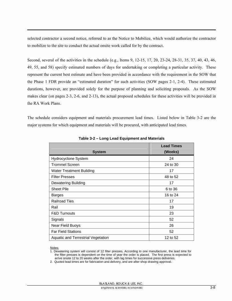
BLASLAND, BOUCK & LEE, INC. engineers, scientists, economists 3-8
selected contractor a second notice, referred to as the Notice to Mobilize, which would authorize the contractor
to mobilize to the site to conduct the actual onsite work called for by the contract.
Second, several of the activities in the schedule (e.g., Items 9, 12-15, 17, 20, 23-24, 28-31, 35, 37, 40, 43, 46,
49, 55, and 58) specify estimated numbers of days for undertaking or completing a particular activity. These
represent the current best estimate and have been provided in accordance with the requirement in the SOW that
the Phase 1 FDR provide an “estimated duration” for such activities (SOW pages 2-1, 2-4). These estimated
durations, however, are provided solely for the purpose of planning and soliciting proposals. As the SOW
makes clear (on pages 2-3, 2-6, and 2-13), the actual proposed schedules for these activities will be provided in
the RA Work Plans.
The schedule considers equipment and materials procurement lead times. Listed below in Table 3-2 are the
major systems for which equipment and materials will be procured, with anticipated lead times.
Table 3-2 – Long Lead Equipment and Materials
System Lead Times
(Weeks)
Hydrocyclone System 24 Trommel Screen 24 to 30 Water Treatment Building 17 Filter Presses 48 to 52 Dewatering Building 17 Sheet Pile 6 to 36 Barges 16 to 24 Railroad Ties 17 Rail 19 F&D Turnouts 23 Signals 52 Near Field Buoys 26 Far Field Stations 52 Aquatic and Terrestrial Vegetation 12 to 52
Notes: 1. Dewatering system will consist of 12 filter presses. According to one manufacturer, the lead time for
the filter presses is dependent on the time of year the order is placed. The first press is expected to arrive onsite 12 to 20 weeks after the order, with lag times for successive press deliveries.
2. Quoted lead times are for fabrication and delivery, and are after shop drawing approval.

4. Phase 1 Monitoring and Compliance with Performance Standards
This section summarizes the monitoring program to be conducted during Phase 1 to assess the performance of
the remedial action against the EPS, QoLPS, and WQ requirements. This section then summarizes how Phase 1
has been designed to meet the numeric standards presented in the Hudson EPS and QoLPS. Compliance with
the processing facility discharge limitations specified in the WQ requirements was discussed in detail in Section
3.6.4.2 of the Phase 1 IDR; the refinements to the water treatment components during the Phase 1 Final Design
have not altered the conclusion that the effluent is expected to meet the WQ discharge limitations for suspended
solids, PCBs, cadmium, chromium, copper, lead, and mercury.
4.1 Phase 1 Environmental Monitoring Plan
An environmental monitoring program will be carried out during Phase 1 to evaluate the project performance
with respect to the EPS, QoLPS, and WQ requirements. The Phase 1 EMP (which is an updated version of the
RA Monitoring Scope that was Attachment B to the SOW, with relatively minor changes to correct
inconsistencies and editorial deficiencies, and to make the document consistent with the Phase 1 Final Design) is
provided in Appendix 7 to this Phase 1 FDR. The Phase 1 EMP describes monitoring of surface water, fish,
sediment residuals, air quality, odor, noise, lighting, and water discharge, as well as special studies that will be
implemented.
The activities described in the Phase 1 EMP will be supplemented and supported by Phase 1 RAM QAPP,
which will be developed in accordance with the SOW. The Phase 1 RAM QAPP will include specific sampling
and analytical protocols, quality assurance/quality control (QA/QC) requirements, and other details necessary
for the implementation of the Phase 1 environmental monitoring program.
4.2 Other Compliance-Related Documents
The Phase 1 RA CHASP included as Appendix 8 to this Phase 1 FDR describes the prevention, response, and
mitigation measures and other activities that will be carried out to address potential hazards to the public and
other impacts that may occur within the vicinity of the Upper Hudson Work Area (as defined in the CD) and are
BLASLAND, BOUCK & LEE, INC. engineers, scientists, economists 4-1

BLASLAND, BOUCK & LEE, INC. engineers, scientists, economists 4-2
associated with the remedial action. The Phase 1 RA CHASP also presents the contingent and mitigative steps
that, when warranted, will be taken during the remedial action to address the QoLPS.
In addition, a Phase 1 PSCP will be developed as part of the RA Work Plan for Phase 1 Dredging and Facility
Operations. This plan will provide guidance on complying with the performance standards and associated
requirements and will provide the basis for certain remedial action plans. It will be based on and consistent with
the PSCP Scope that is Attachment C to the SOW.
4.3 Engineering Performance Standards
In 2003, EPA issued draft EPS for resuspension, PCB residuals, and productivity for the remedial action. A
peer-review panel evaluated the draft standards, after which the final EPS for Phase 1 were issued in April 2004
(EPA, 2004a). One objective of Phase 1 is to test the effectiveness of the remedial design relative to the
performance standards. Although considerable effort has gone into developing a remedial design capable of
achieving the EPS, a number of assumptions had to be incorporated into the design. As a result, there is no
guarantee that the performance standards can be met individually or in combination, and the actual experience in
Phase 1 will provide valuable information on the feasibility of achieving the performance standards. Results
and experience from Phase 1 will be evaluated prior to the start of Phase 2 by GE, EPA, and an independent
peer-review panel; and based on these reviews, changes to the project, design, or performance standards may be
necessary.
This Phase 1 FDR documents that the Hudson EPS have been incorporated into the basis of design for the
remedial action. Specific activities that will be undertaken to address the Hudson EPS during Phase 1 are
described throughout the Phase 1 IDR, this Phase 1 FDR, the Phase 1 EMP, the Phase 1 RA CHASP, and the
PSCP Scope, and will be further described in the Phase 1 RAM QAPP and the Phase 1 PSCP. Where
appropriate and informative, the following summaries provide specific reference to applicable design documents
such as attachments and appendices to this Phase 1 FDR and the associated design documents listed above.
4.3.1 Project-Related Resuspension
As discussed in Section 2.3.4 above, the results of the updated resuspension modeling (Attachment F) using a
%R of 0.35 indicate that suspended solids in the near and far field would be well below the numeric standards

BLASLAND, BOUCK & LEE, INC. engineers, scientists, economists 4-3
and that PCB concentrations in the surface water would be below the control level, with a total Phase 1 PCB
load at TID well below the 65 kg criterion established by EPA for Phase 1. When a 0.70% resuspension loss
rate is used, most of the results are below EPA’s numeric standards, except for the following parameters:
• The 7-day average net PCB flux at TID is predicted to exceed the 600 g/day Control Level; and
• One brief incidence of exceedance of the 300 m near-field TSS standard is predicted.
The installation and operation of the resuspension control systems described in Section 2.3.4 above are predicted
to result in an estimated annual PCB load below the Resuspension Performance Standard criterion (65 kg total
for Phase 1), using both the 0.35 value and the 0.70 value for %R. The model results also indicate that with %R
values of 0.35 and 0.70, the PCB concentration at TID will be below the Control Level of 350 nanograms per
liter (ng/l). The model results show that there is no anticipated need for additional contingent controls other
than those provided for in the west and east channels of Rogers Island, as shown on Figure 3-26 of the Phase 1
IDR, and described in the Phase 1 Project Specifications for Dredging Operations (see Appendix 4, Section
13805).
4.3.2 Dredging Residuals
The Residuals Performance Standard forms the basis of design primarily for dredging, backfilling, and capping.
This standard describes how concentrations of Tri+ PCBs in surface sediment that remain after inventory
dredging will determine when dredging is complete and when backfilling or capping may be implemented. The
action levels will be applied on a CU basis; this process was described in Section 3.3.6 of the Phase 1 IDR. The
influence of the Residuals Performance Standard on the development of the backfilling/capping element,
including the selection of backfill materials and design of engineered cap types, was described in Section 2.3.7
of this Phase 1 FDR.
The final decision regarding the appropriate backfill or cap type that will be placed in each dredged area will be
made after inventory and (if necessary) residuals dredging is complete and residuals concentrations are known.
The primary consideration when selecting the type of backfill material to be placed will be water velocity, which
controls the ability of the selected backfill material to provide a stable substrate to support the habitat
reconstruction and replacement goals for the area. Backfill will not be placed in the navigation channel, if the
finished grade after dredging results in a water depth of less than 15 feet, or in sections of the river where the

BLASLAND, BOUCK & LEE, INC. engineers, scientists, economists 4-4
resultant water depth (following remediation) is desired for habitat purposes. Backfill will not be placed in areas
where post-dredged surficial Tri+ PCB concentrations are less than 0.25 mg/kg, unless necessary to meet
specific habitat goals, as these areas would already meet the substantive requirements of the ROD and the EPS.
Specific areas to be capped will be determined in accordance with the procedures described in the PSCP Scope.
Site-specific cap design is subject to EPA approval as part of the CU completion process. As discussed in
Section 2.3.7.2, two cap types have been developed to act as physical barriers and provide both isolation and
stabilization (see Section 3.9.2.2 of the Phase 1 IDR and the Phase 1 Contract Drawings in Appendix 4 for
details). The two cap types are: 1) Isolation Cap Type A, to be placed in a CU where the average Tri+ PCB
concentration after dredging is less than or equal to 6 mg/kg and capping is necessary; and 2) Isolation Cap
Type B, to be placed in a CU where the average Tri+ PCB concentration is greater than 6 mg/kg after dredging,
and after GE and EPA have determined that additional dredging is not required.
The final cap design and eventual application will be based on practical limitations and efficiency of the
dredging and capping operations, and will account for factors such as cap placement success in previously
capped CU areas, consolidation, and slope stability.
Selection of the appropriate cap type will be made in the field by the Construction Manager, in consultation with
the Design Engineer, and subject to approval by EPA’s field representative. Selection will be based on the
particular river conditions (velocity, habitat, etc.) and the Tri+ PCB concentration in the areas targeted for
capping. Caps will be placed over sampling nodes in the CU such that the arithmetic average Tri+ PCB
concentration of the uncapped nodes is 1 mg/kg or less, and no individual uncapped node has a Tri+ PCB
concentration at or above 15 mg/kg.
The Phase 1 EMP provides an overview of the routine monitoring, reporting requirements, and requirements for
sediment sampling and analysis associated with this performance standard; and the Phase 1 PSCP will describe
the other actions to implement the Residuals Performance Standard. The process for evaluating data, defining
response actions, certifying closure of CUs, and reporting was presented in Section 3.3 of the Phase 1 IDR. CU
checklists have been developed for dredging (inventory and residual), backfill, capping, and habitat
construction. The checklists are provided in Attachment K.

BLASLAND, BOUCK & LEE, INC. engineers, scientists, economists 4-5
4.3.3 Dredging Productivity
The Productivity Performance Standard forms the basis of design primarily for the dredging, dredged material
transport, sediment processing and storage, and transportation and disposal elements of the remedial action.
This standard specifies the annual minimum and target volumes of sediment (in situ volumes, excluding re-
dredging volumes) to be removed, processed, and shipped offsite during Phase 1 (Hudson EPS, Volume 4, p.
27). The dredge schedule designed to meet the Productivity Performance Standard during Phase 1 is discussed
in Section 2.3.2, and all subsequent elements of the Phase 1 Final Design were developed based on the rate of
dredging necessary to achieve the Productivity Performance Standard. Certain contingency actions will be
implemented if specific productivity monitoring thresholds are exceeded; these monitoring thresholds and
contingency actions are described in the PSCP Scope and will be further developed in the Phase 1 PSCP.
4.4 Design Analyses of Attaining Quality of Life Performance Standards
The Final Design of Phase 1 has been developed with the objective of achieving the criteria set forth in the
QoLPS for air quality, odor, noise, lighting and navigation. This subsection summarizes how Phase 1 has been
designed to meet that objective. Detailed descriptions of the QoLPS criteria, associated monitoring,
contingency actions, reporting requirements, and complaint management are provided in the Phase 1 EMP, the
Phase 1 RA CHASP, and/or the PSCP Scope, and are therefore not repeated here. Where appropriate and
informative, the following summaries provide specific reference to applicable design documents such as
attachments and appendices to this Phase 1 FDR and the associated design documents listed above.
Additional design analyses (modeling) relating to attainment of the QoLPS for air quality and noise have been
performed since submittal of the Phase 1 IDR, and are discussed below and in Attachments H and I,
respectively. Analyses relating to attainment of the QoLPS for odor and lighting are based primarily on
information presented in the Phase 1 IDR and are summarized below. Finally, a discussion is presented as to
how the Final Design will comply with the QoLPS for navigation, taking into account the logistical modeling
presented in Attachment D.

BLASLAND, BOUCK & LEE, INC. engineers, scientists, economists 4-6
4.4.1 Air Quality
The QoLPS for air quality contains three components – relating to PCBs in ambient air, opacity, and the
National Ambient Air Quality Standards (NAAQS). Each of these components is discussed below.
4.4.1.1 PCBs in Ambient Air
Although dredged sediments will be exposed to the atmosphere after their removal from the riverbed and thus
could produce PCB emissions to the air, the Phase 1 Final Design has been developed to prevent or mitigate
against unacceptable emissions of PCBs. The numerical criteria in the QoLPS that relate to PCBs consist of a
Concern Level of 0.08 microgram per cubic meter (µg/m3) and a Standard Level of 0.11 µg/m3 (both as 24-hour
average concentrations) in residential areas and a Concern Level 0.21 µg/m3 and a Standard Level of 0.26 µg/m3
(both as 24-hour average concentrations) in commercial/industrial areas. These criteria apply at the locations of
residential or commercial/industrial receptors. To assess attainment of these criteria, air quality modeling has
been conducted for project activities that could produce PCB emissions to the air. The details of this modeling,
including input parameters, methodologies, and results, are provided in Attachment I. The results are
summarized below (by specific project activities), along with a description of preventive and contingency
measures included in the design to meet the PCB criteria for air. This modeling does not include the general site
work and construction of the processing facility, because no PCB-containing materials will be used or
encountered during that work and hence it is not expected that there will be PCB emissions to the air.
Dredging Operations
As discussed in Attachment I, air quality modeling was performed to assess the impacts from dredging
operations, including emissions from the water column during dredging (with and without resuspension
controls) and emissions from open barges filled with sediments at the dredging location. The water column
emissions were modeled using the resuspension model that was presented in Appendix E of the Phase 1 IDR.
The emissions from sediments in the barges were initially modeled using a very conservative emissions model
(the Equilibrium Partitioning Model); and the ambient air concentrations were predicted using an EPA-approved
dispersion model (the Industrial Source Complex [ISC] Model). If this model predicted PCB concentrations at
assessment points to be less than or equal to the applicable control level, then no further modeling was done and
the results were documented. If the Equilibrium Partitioning Model predicted an emission factor that, after
running the ISC model, resulted in a PCB concentration (in air) above the applicable Control Level, then a more

BLASLAND, BOUCK & LEE, INC. engineers, scientists, economists 4-7
complex Transport Limited Model was run to develop a more representative (less conservative) emission factor.
The Equilibrium Partitioning Model and Transport Limited Model are described in Attachment I.
Emissions from barges and the water column were predicted for the entire dredge schedule. The emission
factors are a strong function of PCB concentration in the sediment and meteorological conditions. It was
assumed that barges will be moored at the dredging location for 8 hours while the mechanical dredge loads the
barge. The Equilibrium Partitioning Model predicted that emissions from dredging operations would result in
exceedances of the applicable PCB Concern and Standard Levels at certain nearby residences and commercial
establishments. The contribution of volatilization from the river itself caused by resuspension was negligible;
the exceedances were driven by predicted emissions of PCBs from the open barges. Further, these exceedances
were predicted to occur only when the open barges contain sediments with average PCB concentrations greater
than 200 mg/kg (of which there are predicted to be about 33 during Phase 1) and only during sustained high-
wind conditions, which would promote the volatilization of the PCBs in the sediments. It should also be noted
that additional conservatism was introduced into the modeling by the assumption that the wind across the
surface of the water containing the sediments in the barge would not be reduced by the freeboard of the barge
when it is being filled, which in fact will serve as a wind screen.
The Transport Limited Model, which uses a more realistic representation of emission rates, was then applied to
the barge emissions to further assess emissions rates under the worst-case conditions noted above. This model
indicates that emission rates would be considerably lower than predicted by the Equilibrium Partitioning Model
(less than ¼ in the later stages of filling a barge). Applying these results to the ambient air PCB concentrations
predicted in the initial modeling indicates that the PCB concentrations would not exceed the applicable
residential concern levels or standards at any residential or commercial assessment points.
Since validation of the input conditions and model predictions will not be possible until dredging operations
begin, GE has included in the Final Design a contingency requirement to address the potential that PCB
emissions from the open barges would produce an exceedance of an applicable Concern or Standard Level at an
assessment point. Specifically, the specifications include a requirement that, if the air monitoring indicates such
an exceedance, wind screens will be fitted on the barges that contain sediments with PCB concentrations equal
to or greater than the sediment contained in the barge that was the source of the exceedance. The use of 5-foot
wind screens around the perimeter of such barges would reduce wind speeds across the surface of the water in
the barges by up to 70%; and even the conservative Equilibrium Partitioning Model predicts that, with such
BLASLAND, BOUCK & LEE, INC. engineers, scientists, economists 4-8
wind screens in place, there would be no exceedances of the Concern or Standard Level at any residential or
commercial assessment point.
In these circumstances, the contractor will be directed to have such wind screens available at the work area and
to use them on the barges if monitoring indicates an exceedance of a Control or Standard Level at an assessment
point. The contractor will also be allowed to propose alternative engineering or operational controls if they can
be shown to be effective to meet the QoLPS for PCBs in air.
Barging Operations at Lock 7 and at Sediment Processing Facility Wharf
The model was also run for PCB emissions from barges lined up at Lock 7 (up to three at a time) and from
barges tied up at the sediment processing facility wharf (also up to three at a time). The modeling, using the
Equilibrium Partitioning Model to estimate the emission factors for these cases, predicts no exceedances of
either the residential or the commercial/industrial Concern or Standard Levels. As a result, no mitigation is
necessary.
Processing Facility Operations
At the processing facility, including the waterfront unloading wharf, size separation staging areas, dewatering
and thickening facilities, filter press facility, and material staging and rail yard load-out areas, PCB-containing
materials will at times be exposed to the atmosphere and could therefore become a potential source of PCB
emissions. For uncontrolled emissions from the processing facility operations, the model (assuming emission
rates based on Equilibrium Partitioning Model) predicts exceedances of the applicable Concern and Standard
Levels at both residential and commercial assessment points. A review of the contributing sources indicates that
the two fine-sediment storage areas would be responsible for a large portion of the elevated emissions, with
secondary contributions from the gravity thickener and process water recycle tank.
Several preventive measures have been integrated into the Phase 1 Final Design to control these sources of PCB
emissions during processing operations. Specifically, the Phase 1 Final Design specifies enclosures and
ventilation systems to capture and treat potential PCB emissions from the fine-sediments storage piles (i.e., filter
cake) near the rail yard. The design provides for the ventilation system to control air flow and PCB emissions
by creating negative air pressure within the enclosures to prevent uncontrolled loss of air from the enclosures.
The system includes large fans designed to capture interior air and direct the air flow into GAC units that will
BLASLAND, BOUCK & LEE, INC. engineers, scientists, economists 4-9
remove PCBs before the air is discharged. This system will be used as needed based on monitoring results. The
specifications also call for covers over the gravity thickener and recycle water storage tanks to reduce PCB
emissions. The modeling presented in Attachment I indicates that, with these controls in place, there would be
no predicted exceedances of the applicable PCB Concern or Standard Levels at either residential or
commercial/industrial assessment points. Air quality monitoring as described in the Phase 1 EMP and PSCP
Scope will be conducted during operations to confirm model predictions and, in the event of an exceedance of
air quality Concern or Standard Levels, the contingency monitoring and applicable response actions described in
the Phase 1 EMP and RA CHASP will be implemented.
4.4.1.2 Opacity
Opacity issues may result from vessel, vehicular, or equipment emissions. However, routine maintenance of
diesel engines, generators, and other equipment is expected to achieve the QoLPS for opacity. The Contractors
will maintain and operate vessels and vehicles properly to prevent opacity problems. As discussed in the Phase
1 EMP and Phase 1 RA CHASP, opacity will be monitored by a certified visual observer at the beginning of use
of each piece of equipment or if an opacity complaint is received. If such monitoring shows an exceedance of
the opacity standard, appropriate repairs or other measures will be taken to prevent further exceedances of that
standard.
4.4.1.3 NAAQS
The QoLPS for air quality requires a modeling assessment, during design, of the project’s ability to achieve the
NAAQS for several pollutants subject to those standards (known as “criteria pollutants”). The pollutants for
which such an assessment was required are: respirable particulate matter with a diameter less than 10
micrometers (PM10), fine particulate matter with a diameter less than 2.5 micrometers (PM2.5), carbon monoxide
(CO), sulfur dioxide (SO2), nitrogen oxides (NOx), and ozone (O3) (to be evaluated using its precursors, NOx
and volatile organic compounds [VOCs]). This assessment was required to consist of repeating the assessment
conducted by EPA and reported in EPA’s White Paper – Air Quality Evaluation (2002) (which was included in
the Responsiveness Summary accompanying the ROD), using project-specific design data. If this assessment
validates EPA’s conclusions in that document that the project activities will not exceed the NAAQS, no
additional monitoring or controls for these pollutants are required.

BLASLAND, BOUCK & LEE, INC. engineers, scientists, economists 4-10
Such a modeling assessment has been conducted for the above-listed criteria pollutants. Such modeling has
been conducted for emissions of these pollutants (as relevant) from: a) construction of the processing facility; b)
dredging operations; and c) operation of the processing facility. The details of this modeling, including input
parameters, methodologies, and results, are included in Attachment I to this Phase 1 FDR. The results of this
modeling confirm that the emissions of the criteria pollutants from any of these activities are not predicted to
cause exceedances of the NAAQS. As a result, no provisions for monitoring or contingency actions for the
criteria pollutants are necessary during implementation of this project.
Nevertheless, preventive or contingency measures have been included in the specifications to prevent the
generation of dust during construction of the processing facility. These measures include:
• The contractor must prepare and submit a Site-Specific Dust Prevention and Control Plan that details the
methods to be used to prevent and control onsite dust generation and migration from the site during
construction of the processing facility.
• During site construction, soil piles and open excavations will be wetted down with water, as needed to
prevent dust generation.
• During site construction, haul roads will be wetted down, as needed, to minimize dust generation, and
appropriate covers will be used on trucks hauling fine or dusty material.
• During operations, the contractor shall be required to prevent and mitigate spills of sediment on haul roads.
• The contractor must prepare and submit a Start-up and Testing Plan that describes how each major piece of
equipment will be tested against applicable criteria before operations begin at the processing facility. The
contractor must also prepare and submit an Operations & Maintenance Plan to describe how the facility
will be operated and maintained within specifications.
4.4.2 Odor
River sediments may contain organic matter that, during decomposition, can emit offensive odors from the
natural byproducts of decay, such as hydrogen sulfide (H2S). Because thousands of cubic yards of Hudson
River sediments and debris will be brought to the surface and transported on the waterway and managed at the
processing facility, the QoLPS for odor has been developed to prevent or mitigate unreasonable odors that may
affect community members or others on or near the river and project area. The quantitative QoLPS for odor is

BLASLAND, BOUCK & LEE, INC. engineers, scientists, economists 4-11
0.01 part per million (ppm) (14 μg/m3) of H2S over a 1-hour period, and the qualitative standard is that
complaints are to be investigated and, if appropriate, mitigated.
The Final Design presented in this Phase 1 FDR is expected to comply with the QoLPS for odor. As discussed
in Section 3.11.2.2 of the Phase 1 IDR, sediment cores previously collected from the river for physical and
chemical analyses and treatability studies generally did not have offensive odors. Nevertheless, to minimize
odors and prevent complaints, debris from dredging operations, which may contain wood, vegetation, shellfish,
and other types of organic material, will be screened out and temporarily staged in the size separation area. The
monitoring and contingency requirements that will be implemented under the QoLPS for odor, as well as the
procedures and criteria for responding to an odor compliant, are described in the Phase 1 RA CHASP.
4.4.3 Noise
Noise will inevitably be generated during construction and operation of the processing facility, and during
dredging, backfilling/capping, and sediment transfer operations. The QoLPS for noise specify a number of
numerical criteria, which vary depending on the type of receptor and whether the operations are occurring in the
daytime or nighttime. They are as follows:
• Short-Term Criteria (applicable to facility construction, dredging, and backfilling activities):
─ Residential Control Level (maximum hourly average)
Daytime = 75 decibels (dBA)
─ Residential Standard (maximum hourly average)
Daytime = 80 dBA
Nighttime (10:00 pm – 7:00 am) = 65 dBA
─ Commercial/Industrial Standard (maximum hourly average)
Daytime and nighttime = 80 dBA
• Long-Term Criteria (applicable to sediment processing facility and transfer operations):
─ Residential Standard (24-hour average)
Day-night average = 65 dBA (after addition of 10 dBA penalty to night levels from 10:00 p.m.. to 7:00
a.m.)

BLASLAND, BOUCK & LEE, INC. engineers, scientists, economists 4-12
─ Commercial/Industrial Standard (maximum hourly average)
Daytime and nighttime = 72 dBA
Final design analyses and predictive modeling have been updated since submittal of the Phase 1 IDR. Initially,
the noise modeling was conducted for various sources in the absence of any acoustic controls. The results for
each short-term activity (i.e., facility construction, dredging operations, backfilling, resuspension control
installation) and for long-term continuous activity (i.e., processing facility operations) are discussed below,
along with preventive and/or contingency mitigation measures, where necessary. Details of the noise modeling
analyses, including input parameters, methodologies, and results, are provided in Attachment J.
Processing Facility Site Work and Construction
Construction of the processing facility will involve general earthwork, access road construction, utility
installation, wharf construction, rail yard development, and installation of processing facility equipment. Based
on an assessment of the construction activities with the potential worst-case noise levels, five specific
construction activities were modeled at representative areas: 1) general site construction at the fines staging
area; 2) wharf construction; 3) pile driving to construct the turning and mooring dolphins downstream of Lock
7; 4) construction of the access road north of the processing facility; and 5) earthwork trucks transporting fill
along the access road for processing facility construction. All of these activities are expected to occur only
during the daytime. As discussed in Attachment J, the noise modeling predicts that noise levels resulting from
all of these activities except one will be below the applicable control level (where applicable) and noise standard
at all offsite assessment points. The one exception is the pile driving, using impact hammering, for installation
of the dolphins downstream of Lock 7, which is expected to last approximately 2 weeks. For this activity, the
model predicts that sound levels will exceed the daytime control level of 75 dBA at 11 residences, with four of
those residences also exceeding the daytime residential standard of 80 dBA.
In these circumstances, no mitigation measures are expected to be necessary for noise generated by general site
construction work, wharf construction, access road construction, or earthwork truck traffic on the access road.
However, during construction, surplus general fill (if available) will be used to construct an earthen berm near
the south end of the property, which will help reduce noise from the facility.
For the pile driving of the turning and mooring dolphins downstream of Lock 7, several control/mitigation
options have been considered to reduce these noise levels. However, they all have limitations associated with
BLASLAND, BOUCK & LEE, INC. engineers, scientists, economists 4-13
their implementation and/or uncertainties regarding their effectiveness, as discussed in Attachment J and
summarized below.
• Installation of a sound barrier wall (about 20+ feet high) between the pile driving and the residences should
allow achievement of the applicable criteria, but the installation of that wall would: a) itself generate
considerable noise; b) require design/implementation details to be developed; c) require property access
agreements and easements; and d) may have secondary quality of life issues associated with the architecture
of the wall. In these circumstances, installation of a 20+ foot high wall for temporary noise control for a 2-
week period does not appear to be a practicable approach.
• Another possible option would be to use a temporary barge-mounted sound barrier along the shore.
However, the height of this wall would need to be on the order of 40 feet, which is likely to be impractical
due to structural requirements for wind forces. Again, this approach does not appear to be practicable
• Another potential mitigation option would be to use sound-dampening blankets around the pile-driving
hammerhead. However, actual project data demonstrating the noise-reduction effectiveness of such
blankets have not been identified, and hence it cannot be determined whether such blankets would be
effective in reducing noise levels to achieve the standards.
Given the practical limitations and uncertainties of these options, the design team has not to date identified
control or mitigation options that can practicably and reliably be implemented to reduce the noise levels from
this short-term pile-driving activity to levels below the applicable daytime criteria. The design team is
continuing to investigate potential means to reduce noise levels associated with the pile driving, and will also
seek input from the selected contractor on additional potential techniques. GE will provide an update on this
issue in the RA Work Plan for Phase 1 Facility Site Work Construction.
Dredging and Barging Operations
In-river dredging and barging operations (which include backfilling) require the use of engine-driven dredges,
tugboats, and other equipment that unavoidably generate noise. As discussed in Attachment J, the model
predicts that these operations would meet the daytime residential and commercial/industrial standards of 80dBA
at a distance of approximately 35 feet or more, the daytime residential control level of 75 dBA at a distance of
60 feet or more, and the nighttime residential standard of 65 dBA at a distance of 200 feet or more. These
model results, in conjunction with the locations of assessment points, indicate that noise from dredging and

BLASLAND, BOUCK & LEE, INC. engineers, scientists, economists 4-14
barging operations would produce predicted exceedances of the applicable noise criteria only when these
operations are within 200 feet of residences and only at night.
As discussed in the Phase 1 EMP, a noise study will be conducted at the commencement of dredging to confirm
the equipment sound levels and assumptions used in the modeling. If this study confirms the model predictions,
the dredging contractor will be instructed to reduce noise levels if and when it is necessary to perform dredging
within 200 feet of residences at night. There are a number of measures that the contractor could take to reduce
the noise levels at night. These include use of temporary portable noise shrouds around pumps, use of smaller
work boats instead of tugs to move barges, and/or other operational adjustments on a temporary and as needed
basis.
Sheet Pile Installation
Sheet piling will be used as a resuspension control measure in the EGIA, as discussed in Section 2.3.4 above.
Although sheet pile installation is not a sustained long-term process, driving sheeting with a vibratory hammer
generates noise. Moreover, based on an evaluation of the geotechnical characteristics of the sediment in this
area during Final Design, it has been determined that certain pile-based support structures (batter piles and king
piles) will need to be driven into the bedrock below the sediments to provide a stable and safe sheet pile
resuspension structure. While much of the sheet piling can be installed with a vibratory hammer, an impact
hammer will be needed for driving king piles into the rock. Sheet pile installation will be conducted only in the
daytime and would be expected to last approximately 1 to 2 weeks. It is estimated that this work will include
vibratory hammering approximately 80% of the time and impact hammering for the remaining 20% of the time.
The noise model predicts that the noise levels resulting from vibratory hammering would exceed the daytime
residential and commercial/industrial standard of 80 dBA at a distance of approximately 180 feet and would
exceed the daytime residential control level of 75 dBA at a distance of approximately 325 feet. It also predicts
that the noise levels from impact hammering would exceed the 80 dBA standard at a distance of approximately
325 feet and the 75 dBA residential control level at a distance of approximately 575 feet. If sheet piling is
installed in a portion of EGIA01B as planned, the model predicts that: 1) the noise levels from vibratory
hammering would exceed the daytime residential control level at three nearby residences and the daytime
residential standard at one of those residences; and 2) the noise levels from impact hammering would exceed the
daytime residential Control and Standard Level at the same three residences and the daytime
commercial/industrial standard at one non-residential location.

BLASLAND, BOUCK & LEE, INC. engineers, scientists, economists 4-15
Similar to measures to address the noise impacts of pile driving near Lock 7, several noise control/mitigation
options have been considered for sheet piling in the EGIA, as discussed in Attachment J and summarized below.
• One potential option is the installation of a sound barrier wall along the shoreline between the sheet pile
installation and the residences. However, this option does not appear to be a practical approach for short-
term (1 to 2 weeks) noise control for the same reasons discussed for this option in connection with the
dolphin installation downstream of Lock 7.
• Another possible option would be the use of a temporary barge-mounted sound barrier along the shore
(estimated height of about 30 feet), but this option would not appear to be practical for the same reasons
discussed above and, in any event, would not be feasible when driving sheets adjacent to the shoreline.
• A further potential option is the use of sound-dampening blankets around the pile-driving hammerhead.
However, as noted above, project data demonstrating the noise-reduction effectiveness of such blankets
have not been identified.
In light of these considerations, the design team has not to date identified control or mitigation options that can
practicably and reliably be implemented to reduce the noise levels from the sheet pile installation to levels
below the applicable daytime criteria. Here again, the design team is continuing to investigate potential noise
control or mitigation options for this activity, and will seek input from the selected contractor. GE will provide
an update on this issue in the RA Work Plan for Phase 1 Dredging and Facility Operations.
Processing Facility and Rail Yard Operations
The dewatering and handling of dredged sediments at the processing facility will generate noise as the material
is unloaded at the wharf, processed through a variety of pumps and mechanical equipment, and then transported
by truck to the stockpiles for loading and offsite transport/disposal. Rail yard operations also will generate noise
as locomotives maneuver rail cars and unit trains on and off the property. As discussed in Attachment J, the
noise modeling results indicate that the noise levels from processing facility operations would meet the
applicable long-term noise standards at all commercial/industrial and residential locations around the facility,
except one. The one exception is a residence located on the west side of East Street across the canal from the
unloading wharf and size separation area, where the noise level may exceed the long-term day-night 24-hour
average residential standard level of 65 dBA.

BLASLAND, BOUCK & LEE, INC. engineers, scientists, economists 4-16
To address this predicted exceedance, the specifications require the facility operations contractor to select
equipment that will meet the QoLPS for noise at that assessment point through use of appropriate sizing and best
achievable control technology (BACT) for sound suppression (e.g., mufflers, shrouds, covers). For example, as
explained in Attachment J, the top two sources of noise at the processing facility are the rotary trommel screen
and unloading crane, both located near the waterfront. Trommel screens equipped with sound-dampening
shrouds have been required in the equipment specifications. The contractor will also be required to furnish
sediment unloading equipment rated for a maximum specification of 73 dB at a distance of 100 feet, and
maintain all equipment and vehicles in good working order at all times. These measures should allow
achievement of the noise criteria. Further, if needed based on monitoring, other equipment may be shrouded or
insulated to reduce noise generation, and small sources of noise (e.g., pumps and motors) may be shielded by
placement of small portable sound barriers or other objects to block or reduce sound propagation.
4.4.4 Lighting
To meet the EPA’s Productivity Performance Standard, in-river dredging and onshore processing is expected to
be performed 24 hours a day, 6 days a week, which will unavoidably require nighttime lighting of work areas to
protect worker safety and sufficiently illuminate equipment, transport routes, and operational areas. Because
safety is of paramount importance, lighting requirements for worker safety, navigational safety, and vehicular
safety under the Occupational Safety and Health Administration (OSHA), U.S. Coast Guard (USCG), and other
applicable regulations supersede the QoLPS for lighting. However, design analyses and predictive modeling
indicate that the Final Design presented in this Phase 1 FDR is expected to meet the numerical criteria specified
in the QoLPS for lighting – namely, 0.2 footcandle in rural and suburban residential areas, 0.5 footcandle in
urban residential areas, and 1 footcandle in commercial/industrial areas.
Section 3.11.2.4 of the Phase 1 IDR presented a modeling analysis of lighting impacts from: 1) nighttime on-
water operations (dredging, barge transport, etc.); and 2) nighttime processing facility operations. The modeling
analysis was updated during Final Design to evaluate the potential impacts of light sources from the revised
processing facility layout, and indicates that the design would attain the relevant lighting standards. The results
of this modeling, as well as a description of relevant Phase 1 Project Specifications and Contract Drawings
relating to lighting, are summarized below.

BLASLAND, BOUCK & LEE, INC. engineers, scientists, economists 4-17
On-Water Operations (Dredging, Backfilling/Capping, and Barge Transport)
The modeling described in the Phase 1 IDR indicated that the area in which light from the dredging (or
backfilling/capping) work areas, including the dredge deck and adjacent barge to be loaded, would be above 0.2
footcandle would extend to only about 50 feet from the edge of the lit dredge barge. Thus, there should be no
exceedances of the residential standard of 0.2 footcandle for rural/suburban areas (or of the 0.5 footcandle
residential standard for urban areas, or the 1 footcandle commercial/industrial standard). Note also that light
may be further attenuated by vegetation and other obstructions along shorelines.
Although this modeling indicates that no light mitigation from on-water operations is needed, the applicable
Phase 1 Project Specifications provide lighting requirements that the dredging contractor must follow to prevent,
or mitigate if necessary, exceedances of lighting standards. The contractor must prepare and submit a Lighting
Control Plan that details how lights will be used during on-water operations, including contingencies if
monitoring indicates an exceedance. Further, the contractor is directed to meet applicable QoLPS criteria,
comply with state and federal navigation lighting requirements, and reduce light impacts through use of proper
positioning, shielding, and directing of lights toward work areas and away from potential receptors. If barge-
mounted lighting is employed, such lights will be turned off during transport, although all required navigational
lighting will remain on for safety purposes.
Processing Facility Operations
The nearest receptor potentially affected by nighttime lighting at the sediment processing facility is the golf
course (a commercial facility) located across the Champlain Canal from the waterfront unloading wharf. The
modeling analysis presented in the Phase 1 IDR indicated that the assumed lighting necessary to sufficiently
(i.e., safely) illuminate the unloading wharf would be well below the commercial/industrial standard, and in fact
achieves a level of 0.2 footcandle within the canal itself. In other areas of the processing facility, operations-
specific lighting is to be directed towards specific work areas, equipment, and facilities.
Although these results indicate no need for light mitigation at the processing facility, the applicable Phase 1
Project Specifications provide lighting requirements that the processing facility operations contractor must
follow to prevent, or mitigate if necessary, exceedance of lighting standards. The contractor must prepare and
submit a Lighting Control Plan that details how lights will be used during facility operations, including
contingencies if monitoring indicates an exceedance. Further, the contractor is directed to meet applicable

BLASLAND, BOUCK & LEE, INC. engineers, scientists, economists 4-18
QoLPS criteria, comply with current OSHA standards to allow for safe working conditions, and reduce light
impacts through use of proper positioning, shielding, and directing of lights toward work areas and away from
potential receptors. In addition, the use of low-mast lights and shielding will be required to limit offsite glare.
Moreover, although not required to meet lighting standards, the Final Design optimizes onsite general lighting,
without reducing safety or security, by specifying streetlights for all facility roadway intersections but not
necessarily along all roadways. In addition, care has been taken during design to minimize the number of trees
removed during facility construction, which will further help reduce overall light impacts to surrounding areas.
4.4.5 Navigation
The Upper Hudson River and Champlain Canal are navigable waterways used for recreation and commerce. To
a varying degree by location, season, and time of day, these waterways will be affected during active periods of
the Phase 1 dredging and barge transport activities within designated project areas of the river. Execution of the
project will add marine traffic to the project area waterways in the form of sediment transport barges, tugboats,
and several types of support vessels carrying out vital monitoring, oversight, safety, and other tasks. The
QoLPS for navigation was developed to regulate project-related vessel movement on the river. It requires that
project vessels comply with the applicable provisions of federal and state navigation laws, rules, and regulations.
In addition, it contains a number of other requirements designed to avoid unnecessary interference with non-
project-related vessels while at the same time allowing efficient performance of the project. These requirements
include: restricting access to work areas; providing safe access around those areas in the navigation channel to
the extent practical; notifying the NYSCC of in-river project activities; providing information to the NYSCC
and USCG to allow them to issue Notices to Mariners; providing the public with a schedule of anticipated
project activities; scheduling project-related river traffic so that non-project-related traffic is not unnecessarily
hindered while allowing efficient performance of the project; coordinating lock usage with the NYSCC and its
lock operators; and establishing temporary aids to navigation, such as lighting, signs, and buoys, to maintain
safe and efficient vessel movement.
The Phase 1 Final Design incorporates certain accommodations, preventive control systems, notification
protocols, contingencies, and mitigation measures to maximize safety and productivity and to avoid unnecessary
disruption of non-project-related navigation while allowing efficient performance of the project. Based on Final
Design analyses and results of predictive logistical modeling conducted since submittal of the Phase 1 IDR (see
Attachment D), the Final Design presented in this Phase 1 FDR, including Phase 1 Project Specifications and

BLASLAND, BOUCK & LEE, INC. engineers, scientists, economists 4-19
Contract Drawings and applicable contingencies and mitigation measures, is expected to meet the QoLPS for
navigation.
To meet the QoLPS for navigation, the Phase 1 Final Design includes the requirements outlined below (which
will be specified as requirements in the contract documents where applicable). Additional discussion of the
scope of navigation monitoring, notification, contingencies, mitigation, and complaint management is provided
in Section 3.11.2.5 of the Phase 1 IDR, Section 6 of the Phase 1 PSCP Scope, and Section 4.6 of the Phase 1 RA
CHASP.
• Prohibition on obstructing navigation – To the extent practicable and consistent with meeting other goals
and performance standards, project-related vessels will not be tied or anchored in navigable channels in a
manner that would prevent or obstruct passage of other vessels.
• Vessel lighting and signals – Project-related vessels will comply with applicable federal and state
regulations regarding proper lighting and signaling for safe and orderly navigation, day and night.
• Piloting – Project-related vessels will comply with applicable federal and state regulations regarding
piloting by qualified and properly trained personnel.
• Restricting access – Non-project-related access to active work areas will be restricted in coordination with
the NYSCC. For example, installation of the silt curtain in the east channel of Rogers Island will be
coordinated with the NYSCC, public and mariner notification and signage will be utilized, and buffer zones
will be established to allow safe passage of non-project-related traffic. Although access by non-project
vessels to the Terminal Wall in Fort Edward via the east channel of Rogers Island will be restricted for
safety reasons, the Final Design provides for two ½-hour periods each day – one between 7 am and 9 am,
and another between 3 pm and 5 pm – in which local boat traffic will be allowed into and out of this area.
This access, and the specific timing of the ½-hour window each day, will be at the sole discretion of the
dredging contractor.
• Marine traffic control – Project vessels will be tracked via radio dispatch to schedule and control traffic to
optimize productivity while minimizing interference with non-project-related vessels.
• Use of lock – Use of Lock 7 on the Champlain Canal will be coordinated with the NYSCC and will be
reduced by staging and routing project support vessels (i.e., vessels other than barges and associated tugs)
from the Work Support Marina.
BLASLAND, BOUCK & LEE, INC. engineers, scientists, economists 4-20
• Temporary aids to navigation – Safe and efficient navigation near active project areas will be facilitated
by use of buffer zones and temporary aids to navigation, including lighting, signs, buoys, and other aids
specified by the NYSCC and USCG.
• Routine notices – The NYSCC and USCG will be provided verbal and written routine notices regarding
project schedules, which will allow those agencies to issue Notices to Mariners regarding anticipated access
restrictions, project vessel scheduling, lock scheduling, contingencies, or other information. The general
public will also be provided a schedule of anticipated project activities that may affect navigation, as
discussed in more detail in Sections 4.6.2 and 10.1.1.9 of the RA CHASP.
• Monitoring, notifications, and reporting – Marine traffic will be routinely monitored after dredging
operations begin. This routine monitoring will involve the recording in daily logs of information about river
navigation activities in the vicinity of in-river project operations, along with any resulting navigation issues.
A monthly navigation report will be submitted by GE to EPA and NYSCC, summarizing (in tabular format)
navigation activities for the previous month, including daily records, as well as a log of navigation
compliance and follow up actions. It will also identify any in-river project activities that may significantly
affect navigation by commercial and recreational vessels and that were not previously identified.
• Deviations from navigation requirements and complaint management – If on-river operations deviate
from applicable federal and state navigation regulations listed in the QoLPS for navigation or from the
design plans relating to navigation, the procedures specified in the PSCP Scope and RA CHASP for
reporting and taking contingency actions will be followed. Complaints from the public relating to
navigation will be handled as described in the RA CHASP.
4.5 Summary
As stated above in preceding parts of this section, Phase 1 of the remedial action has been designed to achieve
the Hudson EPS, the WQ requirements, and (with the possible exception of the noise standard in two specific
locations) the QoLPS. However, because each aspect of the design is based on modeling, assumptions, and best
available information, actual monitoring will be needed during the Phase 1 test to determine the ability of the
design to comply with the EPS and QoLPS. Moreover, as discussed in Section 3.11.3 of the Phase 1 IDR, there
are interactions among the standards; certain aspects of compliance with the EPS could counteract efforts to
comply with the QoLPS (or vice versa). For example (in addition to the examples given in the Phase 1 IDR), as
discussed in Section 4.4.3 above, efforts to comply with the navigation standard by installing mooring dolphins
BLASLAND, BOUCK & LEE, INC. engineers, scientists, economists 4-21
and efforts to comply with the resuspension standard by installing sheet piling in the EGIA may impede the
ability to achieve the noise standard for short periods of time.
Given these limitations and potential interactions, it is uncertain as to whether the project will be able to meet all
the EPS and QoLPS simultaneously. During Phase 1, GE will conduct monitoring to determine whether the
various performance standards are being met, and to what extent interactions among performance standards are
causing conflicts and project disruptions or inefficiencies. During implementation of Phase 1, in the event that
there is an exceedance of a performance standard, appropriate contingency actions will be implemented as set
forth in the Phase 1 RA CHASP and other design documents, as well as the Phase 1 PSCP to be developed as
part of the RA Work Plans. Such activities may include equipment repair, operational changes, equipment or
process modifications, additions of equipment, or, in extreme cases, a temporary shutdown of certain operations
– all depending on the circumstances.
5. References BBL. 2005a. Phase 1 Intermediate Design Report (Phase 1 IDR). Hudson River PCBs Superfund Site. Prepared
for General Electric Company, Albany, NY.
BBL. 2005b. Treatability Studies Report (TS Report). Hudson River PCBs Superfund Site. Prepared for
General Electric Company, Albany, NY.
BBL. 2005c. Year 2 SEDC Interim Data Summary Report (Year 2 IDSR). Hudson River PCBs Superfund Site.
Prepared for General Electric Company, Albany, NY.
BBL. 2005d. Supplemental Engineering Data Collection Work Plan Addendum No. 1 (SEDC Work Plan
Addendum No. 1). Hudson River PCBs Superfund Site. Prepared for General Electric Company, Albany, NY.
BBL. 2005e. Supplemental Engineering Data Collection Work Plan Addendum No. 2 (SEDC Work Plan
Addendum No. 2). Hudson River PCBs Superfund Site. Prepared for General Electric Company, Albany, NY.
BBL. 2004a. Preliminary Design Report (PDR). Hudson River PCBs Superfund Site. Prepared for General
Electric Company, Albany, NY.
BBL. 2004b. Treatability Studies Work Plan (TS Work Plan). Hudson River PCBs Superfund Site. Prepared
for General Electric Company, Albany, NY.
BBL. 2004c. Supplemental Engineering Data Collection Work Plan (SEDC Work Plan). Hudson River PCBs
Superfund Site. Prepared for General Electric Company, Albany, NY.
BBL. 2003a. Remedial Design Work Plan (RD Work Plan). Hudson River PCBs Superfund Site. Prepared for
General Electric Company, Albany, NY.
BBL. 2003b. Habitat Delineation and Assessment Work Plan (HDA Work Plan). Hudson River PCBs
Superfund Site. Prepared for General Electric Company, Albany, NY.
BLASLAND, BOUCK & LEE, INC. engineers, scientists, economists 5-1
BLASLAND, BOUCK & LEE, INC. engineers, scientists, economists 5-2
BBL and Exponent. 2005a. Habitat Delineation Report (HD Report). Hudson River PCBs Superfund Site.
Prepared for General Electric Company, Albany, NY.
BBL and Exponent. 2005b. Habitat Assessment Report Phase 1 Areas (Phase 1 HA Report). Hudson River
PCBs Superfund Site. Prepared for General Electric Company, Albany, NY.
BBL and Exponent. 2005c. Supplemental Habitat Assessment Work Plan (SHAWP). Hudson River PCBs
Superfund Site. Prepared for General Electric Company, Albany, NY.
E&E. 2006. Hudson River PCBs Superfund Site Final Biological Assessment (Final BA). Prepared for EPA
(January).
EPA. 2005. Substantive Requirements of State Pollutant Discharge Elimination System Permit for Potential
Discharges to Champlain Canal (land cut above Lock 7) and Substantive Requirements of State Pollutant
Discharge Elimination System Permit for Potential Discharge to the Hudson River.
EPA. 2004a. Final Engineering Performance Standards for Hudson River PCBs Superfund Site (Hudson EPS).
EPA. 2004b. Final Quality of Life Performance Standards for Hudson River PCBs Superfund Site (Hudson
QoLPS).
EPA. 2004c. Hudson River PCBs Superfund Site Final Facility Siting Report (Final Facility Siting Report).
New York, NY. December, 2004.
EPA. 2004d. Final Decision Regarding General Electric Company’s Disputes on Draft Phase 1 Dredge Area
Delineation Report and Draft Phase 1 Target Area Identification Report. July 22, 2004.
EPA. 2002a. Hudson River PCBs Site - Record of Decision and Responsiveness Summary (ROD). New York,
NY.
EPA. 2000. Hudson River PCBs Reassessment RI/FS Phase 3 Report: Feasibility Study (FS). New York, NY.
(December 2000).
BLASLAND, BOUCK & LEE, INC. engineers, scientists, economists 5-3
EPA. 1995a. Guidance for Scoping the Remedial Design. EPA 540/R-95/025. Washington, DC.
EPA. 1995b. Remedial Design/Remedial Action Handbook. EPA 540/R-95/059. Washington, DC.
EPA. 1990. Guidance on EPA Oversight of Remedial Designs and Remedial Actions Performed by Potentially
Responsible Parties. EPA 540/G-90/001. Washington, DC.
EPA/GE. 2005. Consent Decree in United States v. General Electric Company, Civil Action No. 05-cv-1270,
lodged in United States District Court for the Northern District of New York, October 6, 2005.
EPA/GE. 2003. Administrative Order on Consent for Hudson River Remedial Design and Cost Recovery (RD
AOC) (Index No. CERCLA-02-2003-2027). Effective Date August 18, 2003.
EPA/GE. 2002. Administrative Order on Consent for Hudson River Sediment Sampling (Sediment Sampling
AOC) (Index No. CERCLA-02-2002-2023). Effective Date July 26, 2002.
QEA. 2005a. Phase 1 Dredge Area Delineation Report (Phase 1 DAD Report). Hudson River PCBs Superfund
Site. Prepared for General Electric Company, Albany, NY.
QEA. 2005b. Supplemental Delineation Sampling Program Data Summary Report (2004 DSR). Hudson River
PCBs Superfund Site. Prepared for General Electric Company, Albany, NY.
QEA. 2004a. Phase 1 Target Area Identification Report (Phase 1 TAI Report). Hudson River PCBs Superfund
Site. Prepared for General Electric Company, Albany, NY.
QEA. 2004b. Phase 1 Data Summary Report (Phase 1 DSR). Hudson River PCBs Superfund Site. Prepared for
General Electric Company, Albany, NY
QEA. 2003a. Baseline Monitoring Program – Quality Assurance Project Plan (BMP-QAPP). Hudson River
PCBs Superfund Site. Prepared for General Electric Company, Albany, NY.
BLASLAND, BOUCK & LEE, INC. engineers, scientists, economists 5-4
URS. 2006a. Terrestrial Archaeological Survey and Testing Report: Addendum I to the Archaeological
Resources Assessment Report for Phase 1 Dredge Areas. Hudson River PCBs Superfund Site. Prepared for
General Electric Company, Albany, NY.
URS. 2006b. Underwater Archaeological Survey Report: Addendum II to the Archaeological Resources
Assessment Report for Phase 1 Dredge Areas. Hudson River PCBs Superfund Site. Prepared for General
Electric Company, Albany, NY.
URS. 2005. Archaeological Resources Assessment Report for Phase 1 Dredge Areas (Phase 1 ARA Report).
Hudson River PCBs Superfund Site. Prepared for General Electric Company, Albany, NY.
6. Acronyms µg/m3 = micrograms per cubic meter
AOC = Administrative Order on Consent
ARARs = applicable or relevant and appropriate requirements
BA = Biological Assessment
BACT = best achievable control technology
BBL = Blasland, Bouck & Lee, Inc.
BMP = Baseline Monitoring Program
BO = Biological Opinion
CARA = Cultural and Archaeological Resources Assessment
CD = Consent Decree
CDE = Critical Phase 1 Design Elements
CERCLA = Comprehensive Environmental Response, Compensation and Liability Act
cfs = cubic feet per second
CO = carbon monoxide
CPR = Canadian Pacific Railway
CPT = Cone Penetrometer Testing
CU = certification unit
cy = cubic yards
dBA = A-weighted decibels
DGPS = digital global positioning system
DO = Dissolved Oxygen
DoC = depth of contamination
DSR = Data Summary Report
E&E = Ecology and Environment, Inc.
EGIA = East Griffin Island Area
Energy Park = Energy Park/Longe/New York State Canal Corporation
EPA = United States Environmental Protection Agency
EPS = Engineering Performance Standards
FCI = Functional Capacity Index
FS = Feasibility Study
ft/s = feet per second
BLASLAND, BOUCK & LEE, INC. engineers, scientists, economists 6-1

BLASLAND, BOUCK & LEE, INC. engineers, scientists, economists 6-2
g/day = grams per day
g/m2 = grams per square meter
GAC = granular-activated carbon
GE = General Electric Company
gpm = gallons per minute
H2S = hydrogen sulfide
HD Report = Habitat Delineation Report
HDA = Habitat Delineation and Assessment
HDA Work Plan = Habitat Delineation and Assessment Work Plan
HDPE = high-density polyethylene
ISC = Industrial Source Complex
kg = kilogram
m = meter
mg/kg = milligrams per kilogram
MPA = mass per unit area
NAAQS = National Ambient Air Quality Standards
ng/L = nanograms per liter
NOAA = National Oceanic and Atmospheric Administration
NOx = nitrogen oxides
NRHP = National Register of Historic Places
NTIP = Northern Thompson Island Pool
NYS = New York State
NYSCC = New York State Canal Corporation
NYSDEC = New York State Department of Environmental Conservation
O3 = ozone
OM&M = Operation, Maintenance, and Monitoring
OSHA = Occupational Safety and Health Administration
PCBs = polychlorinated biphenyls
PDR = Preliminary Design Report
Phase 1 ARA Report = Archaeological Resources Assessment Report for Phase 1 Dredge Areas
Phase 1 DAD Report = Phase 1 Dredge Area Delineation Report
Phase 1 DSR = Phase 1 Data Summary Report
Phase 1 EMP = Phase 1 Environmental Monitoring Plan

BLASLAND, BOUCK & LEE, INC. engineers, scientists, economists 6-3
Phase 1 FDR = Phase 1 Final Design Report
Phase 1 HA Report = Habitat Assessment Report for Candidate Phase 1 Areas
Phase 1 IDR = Phase 1 Intermediate Design Report
Phase 1 RA CHASP = Phase 1 Remedial Action Community Health and Safety Plan
Phase 1 RAM QAPP = Phase 1 Intermediate Design Remedial Action Monitoring Quality Assurance Project
Plan
PM10 = particulate matter with a diameter less than 10 micrometers
PM2.5 = particulate matter with a diameter less than 2.5 micrometers
ppm = part per million
processing facilities = sediment processing/transfer facilities
PSCP = Performance Standards Compliance Plan
psi = pounds per square inch
QA/QC = quality assurance/quality control
QEA = Quantitative Environmental Analysis, LLC
QoLPS = Quality of Life Performance Standards
R&D = receiving and departure
RA CHASP = Remedial Action Community Health and Safety Plan
RD AOC = Administrative Order on Consent for Hudson River Remedial Design and Cost Recovery
RD Work Plan = Remedial Design Work Plan
RIP = repair in place
RM = river mile
ROD = Record of Decision
RSSCTs = Rapid Small-Scale Column Tests
SAV = submerged aquatic vegetation
SEDC = Supplemental Engineering Data Collection
SEDC Work Plan = Supplemental Engineering Data Collection Work Plan
Sediment Sampling AOC = Administrative Order on Consent for Hudson River Sediment Sampling
SHAWP = Supplemental Habitat Assessment Work Plan
SHPO = State Historic Preservation Office
SO2 = sulfur dioxide
SOW = Statement of Work
SSAP = Sediment Sampling and Analysis Program
TID = Thompson Island Dam

BLASLAND, BOUCK & LEE, INC. engineers, scientists, economists 6-4
TOC = total organic carbon
TS Report = Treatability Studies Report
TS Work Plan = Treatability Studies Work Plan
TSCA = Toxic Substances Control Act
TSS = total suspended solids
URS = URS Corporation
USACE = United States Army Corps of Engineers
USCG = United States Coast Guard
USFWS = U.S. Fish and Wildlife Service
USGS = United States Geological Survey
VOC = volatile organic compound
Year 2 SEDC IDSR = Year 2 SEDC Interim Data Summary Report