Executive Summary Phase 3
33
2019-12-11 | Page 1 Executive Summary Phase 3 Ericsson AG 11th December 2019
Transcript of Executive Summary Phase 3

2019-12-11 | Page 1
Executive Summary Phase 3
Ericsson AG 11th December 2019

2019-12-11 | Page 2
35gAgenda
ObjectiveTurn around to reach profit by 2020
2
4
ObjectiveTurn around to reach profit by 2020
5
Our customers’ priorities Digital engagements, automated operations, programmable networks
End to End Architecture and Benefits
Our customers’ priorities Digital engagements, automated operations, programmable networks
Radio Dimensioning Process and Results
Our customers’ priorities Digital engagements, automated operations, programmable networks
Radio Planning Validation
Our customers’ priorities Digital engagements, automated operations, programmable networks
Radio Redundancy Configurations
Our customers’ priorities Digital engagements, automated operations, programmable networks
Wrap Up6
1 Our customers’ priorities Digital engagements, automated operations, programmable networks
Moving from 4G to 5G

2019-12-11 | Page 3
35gAgenda
ObjectiveTurn around to reach profit by 2020
2
4
ObjectiveTurn around to reach profit by 2020
5
Our customers’ priorities Digital engagements, automated operations, programmable networks
End to End Architecture and Benefits
Our customers’ priorities Digital engagements, automated operations, programmable networks
Radio Dimensioning Process and Results
Our customers’ priorities Digital engagements, automated operations, programmable networks
Radio Planning Validation
Our customers’ priorities Digital engagements, automated operations, programmable networks
Radio Redundancy Configurations
Our customers’ priorities Digital engagements, automated operations, programmable networks
Wrap Up6
1 Our customers’ priorities Digital engagements, automated operations, programmable networks
Moving from 4G to 5G

2019-12-11 | Page 4
Standardization & Industry: moving from 4G to 5GBenefits of 5G and NR (New Radio)
Enhanced Network Slicing support
— E2E network slice identifier (NSSAI)
— Improved network slice isolation (NSSF)
— Multiple network slices per device
Service Based Architecture for agility
— IT architecture principles
— Allows fast new service creation
— Extensibility and reuse
Less complex RAN and UE architecture
— Reduced signaling
— Lower control-plane latency
— Less complex RAN and UE architecture
Target architecture for new use cases and innovation
— Industry eco-system focus on 5GC and NR
— One Core for all access type (including fixed, Wi-Fi)
EPC*+5GCDual Mode Core
EPC* - is 5G enabled LTE Core
Ericsson View

2019-12-11 | Page 5
35gAgenda
ObjectiveTurn around to reach profit by 2020
2
4
ObjectiveTurn around to reach profit by 2020
5
Our customers’ priorities Digital engagements, automated operations, programmable networks
End to End Architecture and Benefits
Our customers’ priorities Digital engagements, automated operations, programmable networks
Radio Dimensioning Process and Results
Our customers’ priorities Digital engagements, automated operations, programmable networks
Radio Planning Validation
Our customers’ priorities Digital engagements, automated operations, programmable networks
Radio Redundancy Configurations
Our customers’ priorities Digital engagements, automated operations, programmable networks
Wrap Up6
1 Our customers’ priorities Digital engagements, automated operations, programmable networks
Moving from 4G to 5G

2019-12-11 | Page 6
Network Sharing
How?Where?
Station
SBB MNO

2019-12-11 | Page 7
User Part
Cell
PDN GW, User Database & apps
Control Part
NR RU + BB
Operator A’s HW/SW and spectrum
Operator B’s HW/SW and spectrum
Shared HW and Frequency when on Cell level
Site Sharing
User plane only
Control plane and User plane
Multi OperatorCore Network
(MOCN)
Multi-Operator RAN
(MORAN)
GeographicalSplit Networks
(Nationalroaming)
Lower control & differentiation - Shared spectrum
Defined by 3GPP
If network sharing, these are the options
Multi-Operator RAN
(MORAN)
Multi-Operator RAN
(MORAN)
Shared Baseband enabling mechanisms in
3GPP
No need of 3GPP
specifications
Higher control & differentiation (non Shared Spectrum)

2019-12-11 | Page 8
Sharing
SBB Network Scenarios
NR
2
Option 2
SBB own NW
gNB
5GCN 5GCN
NR BB
RU
gNB
Multi Operator Core Network (MOCN)
5GCN 5GCN
gNB
Multi Operator RAN(MORAN)
- Combined Spectrum of SBB & MNO
- Separate Core Networks
- Optional common radio hardware
- SBB own spectrum
- Separate Core Networks
- Common radio hardware
NR BB
RU
Shared HW
SBB MNO
MNO(End to End Slicing)
- MNO Spectrum
- Service access through MNO slice
gNB
MNO HW
5GCN
NR BB
RU
5GCN
- SBB own Spectrum

2019-12-11 | Page 9
Nominal dimensioning example:
— Frequency 1900 MHz
— Bandwidth 10 MHz
— EIRP 40dBm
— TDD 50:50
— UL Cell Edge Thrp. 5Mbps
— Redundancy*
— ISD 2.41km (h=16m) / 2.76km (h=22m)
— Start with LTE POC (Option 1 in 3GPP) and reuse the current available UE ecosystem
— Migrate to final target with full NR radio network and 5GC core when NR UE ecosystem is ready
— SW migration from LTE to 5G with:
— Dual-mode Core
— SW upgrade on radio side
— Full Independence from MNO
— For non critical services, a MNO slice can be still used
SBB own Network Scenario
LTE NR
2
Dual-mode Core(EPG,5GC)
Option 1 Option 2
Migration
Full SBB NW
1
Device EcosystemLTE NR
eNB gNB
*Redundancy: The redundant layer is in Standby
mode and is prepared to go ON AIR on demand
eNB
POC

2019-12-11 | Page 10
— A MOCN scenario requires close cooperation and governance with MNO.
— Radio network components should come from the same vendor to benefit from:
— Carrier aggregation
— Features that rely on lower protocol levels (eg. CoMP)
— A common deployment needs to be agreed with MNO and SW level compliance between Radio and Core needs verification
— Radio dimensioning results (Intercell distance) for an SBB owned network can be considered as an upper bound
Multi Operator Core Network (MOCN) Scenario
5GCN 5GCN
NR BB
RU
SA MOCN
(Option 2)
NR BB RU
gNBgNB
NR BB
RU

2019-12-11 | Page 11
— A MORAN scenario creates a dependancy on MNO:
— Same coverage area
— Same SW level required (may be hard to match the align SBB and MNO requirements)
— Infrastructure management
— Independent Radio spectrum
— This scenario provides mainly CAPEX saving without radio performance benefits
Multi Operator Radio Access Network (MORAN)
5GCN 5GCN
gNB
NR BB
RU

2019-12-11 | Page 12
35gAgenda
ObjectiveTurn around to reach profit by 2020
2
4
ObjectiveTurn around to reach profit by 2020
5
Our customers’ priorities Digital engagements, automated operations, programmable networks
End to End Architecture and Benefits
Our customers’ priorities Digital engagements, automated operations, programmable networks
Radio Dimensioning Process and Results
Our customers’ priorities Digital engagements, automated operations, programmable networks
Radio Planning Validation
Our customers’ priorities Digital engagements, automated operations, programmable networks
Radio Redundancy Configurations
Our customers’ priorities Digital engagements, automated operations, programmable networks
Wrap Up6
1 Our customers’ priorities Digital engagements, automated operations, programmable networks
Moving from 4G to 5G

2019-12-11 | Page 13
SBB Own spectrum and maximum power optionsPowers based on PT1 draft
900MHz coexistence and Blocking B8 Band
Scenario selection and max EIRP evaluation
1900MHz coexistence and Blocking B1 Band
𝟐𝟕. 𝟖 𝒅𝑩𝒎 𝟏𝟗. 𝟓 𝒅𝑩𝒎 𝟐𝟏. 𝟕 𝒅𝑩𝒎 𝟒𝟑𝒅𝑩𝒎 𝟑𝟎𝒅𝑩𝒎EIRP
1900 1920 1925
Sunrise 3G
B1
19051910 1915
92
0.7
92
5
91
9.3
FRMCS
300KHz
GSM-R
92
1 92
5
91
8
FRMCS GSM-R
92
3
92
5
91
8
FRMCS GSM-R
92
0
92
5
91
8
FRMCS
1.4 𝑀𝐻𝑧 3 𝑀𝐻𝑧 5 𝑀𝐻𝑧 5 𝑀𝐻𝑧
𝟓𝟗. 𝟕 𝒅𝑩𝒎
𝟒𝟎𝒅𝑩𝒎
𝟑𝟑𝒅𝑩𝒎

2019-12-11 | Page 14
5G RF Simulation Methodology for SBB Spectrum
Methodology similar as in SBB Phase 2:
— Set link budget parameters— Power, antenna gains, losses, margins etc.
— Set target Uplink (UL) Cell Edge Throughput targets— 1,3,5, [10] Mbps
— Solve for maximum propagation loss to achieve the target UL throughput:— Allow limiting by Downlink control channel coverage
— From maximum propagation loss:— Set nominal antenna height and propagation model— Calculate inter-cell distances for different antenna heights
— The powers (EIRP) used are based on last PT1 draft report — 1900MHz, MCL based on 100m site spacing (worst case
scenario)— as per TS.137.104, Table 6.6.2.1-1
Intercell distance
Cell edge throughput

2019-12-11 | Page 15
Maximum Intercell Distance High Utilization, Suburban, 16m BS height
1900MHz/10 MHz TDD 50:50
— Intercell distance ~3.1 km
— 3 Mbps cell edge UL, 1.7 Mbps DL
900 MHz/5MHz FDD
— Intercell distance ~7 km for (3 Mbps cell edge UL)
— Not limited by DL control channels with increased DL power (59.7 dBm)
NR900 / 5MHz
59.7 dBm
NR1900/5MHz
30 dBm
NR1900/5MHz
43 dBm
NR1900/10 MHz
40 dBm
*
- Downlink control channel limited scenarios shown with *
- UL/DL bitrates shown as labels
- Power is EIRP

2019-12-11 | Page 16
Maximum Intercell Distance –different TDD patternHigh Utilization, Suburban, 16m BS height
Different TDD pattern
• 80% of TDD slots are used for Uplink
NR900 / 5MHz
59.7 dBm
NR1900/5MHz
30 dBm
NR1900/5MHz
43 dBm
NR1900/10 MHz
40 dBm
- Downlink control channel limited scenarios shown with *
- UL/DL bitrates shown as labels
- Power is EIRP
**
*
1900MHZ/10 MHz TDD 20:80• Intercell distance increases from
3.1 km to 3.8 km • 3 Mbps cell edge UL bitrate• DL bitrates reduced (0.4 Mbps)

2019-12-11 | Page 17
Intercell Distance vs TDD Patterns1900 MHz. 16 m BS antenna height, High Loading
— Using a 20:80 pattern can increase uplink bitrates
— at the expense of downlink cell edge bitrates
* * *
- Downlink control channel limited scenarios shown with *
- UL/DL bitrates shown as labels
- Power is EIRP
5MHz / 30 dBm 5MHz / 43 dBm 10 MHz / 40 dBm
*

2019-12-11 | Page 18
Impact of using different antennas4T4R and 8T8R Radios
Larger antennas and more feeders are needed for 4T4R and 8T8R
— 4T4R and 8T8R radio configurations can provide uplink and downlink performance improvements
— Downlink beamforming gains of approximately 3 dB and 6 dB
— However downlink powers must be reduced to keep EIRP constant
— Limits DL throughput gains
— Potential to increase uplink coverage by approximately:
— 3 dB (4T4R)
— 6 dB (8T8R)
— 5G Multi User-MIMO is not applicable for general railway track coverage
— Could be used for main stations and shunting yards for higher capacity
2T2R 4T4R 8T8R
Radio (2T2R)
Radio (4T4R)
Radio (8T8R)
2019-12-11 | Page 19
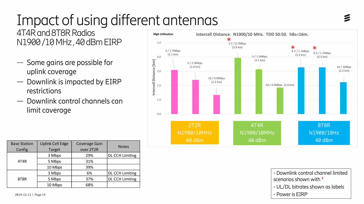
Impact of using different antennas 4T4R and 8T8R RadiosN1900 /10 MHz , 40 dBm EIRP
2T2R
N1900/10MHz
40 dBm
4T4R
N1900/10MHz
40 dBm
8T8R
N1900/10Hz
40 dBm
**
*— Some gains are possible for
uplink coverage
— Downlink is impacted by EIRP restrictions
— Downlink control channels can limit coverage
Base Station
Config
Uplink Cell Edge
Target
Coverage Gain
over 2T2RNotes
3 Mbps 29% DL CCH Limiting
4T4R 5 Mbps 31%
10 Mbps 39%
3 Mbps 6% DL CCH Limiting
8T8R 5 Mbps 37% DL CCH Limiting
10 Mbps 68%
- Downlink control channel limited scenarios shown with *
- UL/DL bitrates shown as labels
- Power is EIRP

2019-12-11 | Page 20
Antenna Height Impact on Intercell distance22m vs 16m, TDD 50:50
— Using a 22m antenna height can result in a larger cell spacing for the same uplink cell edge bitrate
— ~ 16% larger Intercell distance for NR 1900 MHz is possible for 3Mbps UL cell edge throughput
NR1900/5MHz
30 dBm EIRP
NR1900/5MHz
43 dBm EIRP
NR1900/10 MHz
40 dBm EIRP
NR900 / 5MHz
59.7 dBm EIRP
Non Line of Sight propagation model is assumed

2019-12-11 | Page 21
Summary 5G radio dimensioning
— NR at 1900MHz (50:50 TDD) with 10 MHz bandwidth can be used to achieve:
— ~3 km site spacing for a 3 Mbps uplink cell edge bitrate
— A different TDD pattern (20:80) can be used to increase uplink throughput and coverage
— At the expense of downlink throughput
— 4T4R and 8T8R can be used to increase uplink performance
— Downlink performance gains not achieved due to EIRP limitations
— Larger antennas will be required
— Simulations results are derived using a proven conservative approach:
— Maximum allowable downlink powers are based on a 100m distance to adjacent spectrum systems (CEPT & PT1).
— Suburban propagation model used with 98% probability cell edge performance.
— Used link performance curves based on system simulator.

2019-12-11 | Page 22
35gAgenda
ObjectiveTurn around to reach profit by 2020
2
4
ObjectiveTurn around to reach profit by 2020
5
Our customers’ priorities Digital engagements, automated operations, programmable networks
End to End Architecture and Benefits
Our customers’ priorities Digital engagements, automated operations, programmable networks
Radio Dimensioning Process and Results
Our customers’ priorities Digital engagements, automated operations, programmable networks
Radio Planning Validation
Our customers’ priorities Digital engagements, automated operations, programmable networks
Radio Redundancy Configurations
Our customers’ priorities Digital engagements, automated operations, programmable networks
Wrap Up6
1 Our customers’ priorities Digital engagements, automated operations, programmable networks
Moving from 4G to 5G

PA1 | 2019-10-16 | Ericsson Confidential | Page 23
Planet Inputs and service level requirements

2019-12-11 | Page 24
Planet Mentum ValidationRSRP Coverage Whole Track
Inputs Planning Tool
for selected scenario
• Rolle-Villeneuve 72km
• Green Field Planning
• 1900 MHz TDD Band (50:50)
• 10 MHz bandwidth (1900–1910)
• 22m Antenna height
• EIRP (Max TX PWR + Ag) = 40dBm
• 50% downlink loading
• 2dB uplink interference margin
• 98% Coverage Probability Factor
• SS-RSRP Threshold -124 dBm
• UL Throughput Threshold 5Mbps
• Resulting Intercell Distance ~2.2km

2019-12-11 | Page 25
Planet Mentum ValidationRSRP Coverage Example
Conclusion
• Spacing between sites should not be assumed
as a general network planning rule in Switzerland,
especially on selected track Rolle-Villeneuve due
to different environments such as rural, sub-
urban, urban, tunnels and mountainous.
• In the detailed document are presented the
RSRP, SINR, DL&UL Average Throughputs
Simulations which corresponds to theoretical
predictions, but are very dependent on the end
selected scenario.

2019-12-11 | Page 26
35gAgenda
ObjectiveTurn around to reach profit by 2020
2
4
ObjectiveTurn around to reach profit by 2020
5
Our customers’ priorities Digital engagements, automated operations, programmable networks
End to End Architecture and Benefits
Our customers’ priorities Digital engagements, automated operations, programmable networks
Radio Dimensioning Process and Results
Our customers’ priorities Digital engagements, automated operations, programmable networks
Radio Planning Validation
Our customers’ priorities Digital engagements, automated operations, programmable networks
Radio Redundancy Configurations
Our customers’ priorities Digital engagements, automated operations, programmable networks
Wrap Up6
1 Our customers’ priorities Digital engagements, automated operations, programmable networks
Moving from 4G to 5G

2019-12-11 | Page 27
Radio Redundancy concepts
— The redundant layer is in Standby mode and is prepared to go ON AIR on demand.
— This scenario is independent from any other spectrum asset.
— Redundancy cannot be assured if one site fails (e.g. tower collapse).
— This scenario mitigates with one offset site broadcasting cells on different band when the spectrum would be become available.
— The additional redundant bandwidth can be used as a carrier aggregation layer to increase the performance in normal operation.

2019-12-11 | Page 28
Baseband Redundancy Concept
— In order to achieve baseband hardware redundancy two inter-frequency overlapped cells on two basebands covering the same area needs to be configured.
— Two frequency bands are required.
— Dual Connectivity (or Carrier Aggregation) can be used to split traffic over two cells. In case of BaseBand (BB) or Radio Unit failure system works with reduced bandwidth
— Due to bandwidth split over two overlapping cells, load sharing between the cells will be required to minimize performance degradation.
Radio
Baseband

2019-12-11 | Page 29
Baseband and Radio Unit Redundancy concept
— Radio Unit redundancy can be obtained with Combined cell option where two radio units are configured as one combined cell, if one radio fails, the cell is still enabled with one sector-carrier to provide service.
— With Combined Cell, several radio units operating different sectors can be part of the same cell (same PCI).
— By combining BB and RU redundancy full redundancy can be achieved i.e. each combined cell is severed by 2 radio units with mixed mode radio capability.
— If either radio unit fails, the two cells are still enabled with another radio; if any Baseband unit fails, one cell is lost while the remaining cell will still have combined cell functionality with two radios.

2019-12-11 | Page 30
35gAgenda
ObjectiveTurn around to reach profit by 2020
2
4
ObjectiveTurn around to reach profit by 2020
5
Our customers’ priorities Digital engagements, automated operations, programmable networks
End to End Architecture and Benefits
Our customers’ priorities Digital engagements, automated operations, programmable networks
Radio Dimensioning Process and Results
Our customers’ priorities Digital engagements, automated operations, programmable networks
Radio Planning Validation
Our customers’ priorities Digital engagements, automated operations, programmable networks
Radio Redundancy Configurations
Our customers’ priorities Digital engagements, automated operations, programmable networks
Wrap Up6
1 Our customers’ priorities Digital engagements, automated operations, programmable networks
Moving from 4G to 5G

2019-12-11 | Page 31
Sharing/Slicing options have an operator dependency. Cooperation/agreement is needed to secure the critical communication requirements in terms of availability and reliability.
SBB Network Scenarios
NR
2
Option 2
Own SBB NW
gNB
5GCN 5GCN
NR BB
RU
gNB
Multi Operator Core Network (MOCN)
5GCN 5GCN
gNB
Multi Operator RAN(MORAN)
- Shared/combined Spectrum of SBB & MNO
- Separate Core Networks
- Optional common radio hardware
- SBB own spectrum
- Separate Core Networks
- Common radio hardware
- Mainly CAPEX savings
NR BB
RU
Shared HW
SBB MNO
MNO(End to End Slicing)
- MNO Spectrum
- Service access through MNO slice
gNB
MNO HW
5GCN
NR BB
RU
5GCN
- SBB own Spectrum

2019-12-11 | Page 32
Wrap-UpCoverage Conclusions for the potential railway spectrum
— 1900MHz/10MHz is a viable solution for critical rail communications*
— 3 km intercell distance can be achieved for a 3 Mbps uplink cell edge bitrate
— Multi array antennas like 4T4R/8T8R and advanced features are options to increase the uplink performance.
— Using 5G instead of 4G slightly increases the throughput.
— By increasing the mast height from 16m to 22m the inter cell distance can be increase by approx. 16% by keeping same cell edge throughput.
— A different TDD pattern (20:80) can be used to increase uplink throughput and coverage:
— At the expense of downlink throughput
* Final service level requirements for railway communications are still to be confirmed.