ExEcutivE Summary - Intel · PDF fileExEcutivE Summary Developers today are ... both container...
28
EXECUTIVE SUMMARY Developers today are driving businesses toward adopting containerized applications as a way to accelerate software delivery. Containers help developers quickly iterate applications through development cycles and improve business competitiveness by enabling a quicker time to market for new services. However, for businesses to put these quickly developed applications into production, the applications need to meet advanced security requirements that containers do not inherently meet on their own. Traditional applications that are hosted in virtual machines (VMs), on the other hand, do provide a higher level of security through operating system (OS)-level isolation and the reduced attack surface of a hypervisor. This situation presents a problem: how can businesses provide the same level of security offered by hypervisor-based workloads while also offering the advantages of container-based applications in the development cycle? And how can a single environment support both types of workloads in a simple way? VMware Cloud Foundation™, based on VMware vSphere®, provides a cloud platform that meets advanced security needs for VM-based workloads. By adding VMware vSphere® Integrated Containers™ to this environment, businesses can deploy containers, too, on the same hypervisor. This strategy extends the advanced security features of VM-based workloads—such as role-based access control, identity management, and OS-level isolation—to containerized applications. This reference architecture presents configuration details for building a unified cloud solution through which an organization can build and run applications hosted on both VMs and containers in a more secure way. From a software perspective, the solution consists of VMware Cloud Foundation with vSphere Integrated Containers installed as an add-on component. The hardware for the solution consists of a single rack of Dell EMC™ PowerEdge™ servers with Intel® processors, Intel® Solid-State Drives (SSDs), and Intel® Ethernet Network Adapters, along with switches from Cisco and Dell. BUILDING A UNIFIED CLOUD PLATFORM FOR VMS AND CONTAINERS Container technologies, such as Docker*, are popular among developers today for their ability to help speed application delivery and ensure the portability of applications from one environment to another. The advantages offered by containers are especially useful for applications developed as a set of microservices—a robust architectural model that many consider to be the future standard in global-scale applications. A Secure, Unified Cloud Platform to Host Both VM-based and Container-based Applications Intel® Builders Enterprise Data Center Authors Krzysztof Ciepłucha, Cloud Solutions Architect, DCG, DSG, ESS, Intel Patryk Wolsza, SDI Solutions Architect and Engineer, DCG, DSG, ESS, Intel Łukasz Redynk, Cloud Solutions Engineer, DCG, DSG, ESS, Intel Jennifer Lankford, Intel Joe Carvalho, Director, Ecosystem Technology Strategy, RSD, Intel T. Sridhar, Principal Engineer & Chief Ecosystem Technologist, VMware Kris Applegate, Solution Architect, Customer Solution Centers, Dell EMC REFERENCE ARCHITECTURE
-
Upload
trinhnguyet -
Category
Documents
-
view
219 -
download
0
Transcript of ExEcutivE Summary - Intel · PDF fileExEcutivE Summary Developers today are ... both container...

ExEcutivE SummaryDevelopers today are driving businesses toward adopting containerized applications as a way to accelerate software delivery. Containers help developers quickly iterate applications through development cycles and improve business competitiveness by enabling a quicker time to market for new services.
However, for businesses to put these quickly developed applications into production, the applications need to meet advanced security requirements that containers do not inherently meet on their own. Traditional applications that are hosted in virtual machines (VMs), on the other hand, do provide a higher level of security through operating system (OS)-level isolation and the reduced attack surface of a hypervisor. This situation presents a problem: how can businesses provide the same level of security offered by hypervisor-based workloads while also offering the advantages of container-based applications in the development cycle? And how can a single environment support both types of workloads in a simple way?
VMware Cloud Foundation™, based on VMware vSphere®, provides a cloud platform that meets advanced security needs for VM-based workloads. By adding VMware vSphere® Integrated Containers™ to this environment, businesses can deploy containers, too, on the same hypervisor. This strategy extends the advanced security features of VM-based workloads—such as role-based access control, identity management, and OS-level isolation—to containerized applications.
This reference architecture presents configuration details for building a unified cloud solution through which an organization can build and run applications hosted on both VMs and containers in a more secure way. From a software perspective, the solution consists of VMware Cloud Foundation with vSphere Integrated Containers installed as an add-on component. The hardware for the solution consists of a single rack of Dell EMC™ PowerEdge™ servers with Intel® processors, Intel® Solid-State Drives (SSDs), and Intel® Ethernet Network Adapters, along with switches from Cisco and Dell.
Building a unifiEd cloud Platform for vmS and containErSContainer technologies, such as Docker*, are popular among developers today for their ability to help speed application delivery and ensure the portability of applications from one environment to another. The advantages offered by containers are especially useful for applications developed as a set of microservices—a robust architectural model that many consider to be the future standard in global-scale applications.
A Secure, Unified Cloud Platform to Host Both VM-based and Container-based Applications
Intel® BuildersEnterprise Data Center
AuthorsKrzysztof Ciepłucha, Cloud
Solutions Architect, DCG, DSG, ESS, Intel
Patryk Wolsza, SDI Solutions Architect and Engineer, DCG, DSG,
ESS, Intel
Łukasz Redynk, Cloud Solutions Engineer, DCG, DSG, ESS, Intel
Jennifer Lankford, Intel
Joe Carvalho, Director, Ecosystem Technology Strategy, RSD, Intel
T. Sridhar, Principal Engineer & Chief Ecosystem Technologist, VMware
Kris Applegate, Solution Architect, Customer Solution Centers, Dell EMC
RefeRence ARchitectuRe

However, a challenge arises for many DevOps engineers and IT ops teams as containers continue to grow in popularity among developers: how can today’s software-defined data centers (SDDCs) add support for containers in the most frictionless way possible while also taking into consideration the security, compliance, and monitoring that enterprise applications need?
VMware Cloud Foundation deployed with vSphere Integrated Containers offers a simple and compelling solution for securing and supporting containers within existing environments that already support VMs based on VMware ESXi™, without requiring any retooling or rearchitecting of the network. Cloud Foundation with vSphere Integrated Containers provides a unified, seamless platform for managing both VMs and Docker containers in a way that builds on a company’s existing VMware® security infrastructure and administrators’ familiarity with vSphere.
What Is VMware Cloud Foundation™?VMware Cloud Foundation is a suite of services, built on the vSphere cloud computing platform, whose components work together to provide a managed, hyper-converged, and highly secure cloud-software infrastructure for VM-based workloads. The main components in the VMware Cloud Foundation suite are vSphere, VMware NSX®, VMware vSAN™, and VMware SDDC Manager™.
What Is VMware vSphere® Integrated Containers™?vSphere Integrated Containers is a Docker-compatible container engine that can be installed on top of vSphere to extend the hosting and management capabilities of that platform to include containers. Once vSphere Integrated Containers is installed, both developers and administrators can provision and manage containers through the VMware Cloud Foundation management tools and a command prompt. vSphere Integrated Containers also extends the management functionality of VMware Cloud Foundation by allowing developers to securely store and manage both container images and running instances of containerized apps.
This document describes a specific do-it-yourself (DIY)-type implementation of this cloud platform and provides details about the specific hardware and software needed for deployment. The particular implementation described in this reference architecture runs on qualified Dell EMC™ and Intel hardware and has been validated as a fully functional solution by a team of Intel engineers.
Figure 1. The validated solution described in this paper consists of VMware vSphere Integrated Containers and VMware Cloud Foundation running on Dell EMC PowerEdge servers with Intel® SSDs
Reference Architecture | A Secure, Unified Cloud Platform to Host Both VM-based and Container-based Applications
Contents
Executive Summary . . . . . . . . . . . . . . . . . . . . .1
Building a Unified Cloud Platform for VMs and Containers . . . . . . . . . . . . . . . . . . . . . . . . . .1
What Is VMware Cloud Foundation™? . . .2
What Is VMware vSphere® Integrated Containers™? . . . . . . . . . . . . . . . . . . . . . . . . .2
Solution Architecture . . . . . . . . . . . . . . . . . . . .3
Overview . . . . . . . . . . . . . . . . . . . . . . . . . . . . .3
Solution Architecture: Software . . . . . . .3
Solution Architecture: Hardware . . . . . . .4
Configuration Guidance . . . . . . . . . . . . . . . . . .6
Overview of the Configuration Steps . . .6
Installing and Configuring VMware Cloud Foundation . . . . . . . . . . . . . . . . . . . . .6
Installing and Configuring vSphere Integrated Containers . . . . . . . . . . . . . . . . .9
Understanding the vSphere Integrated Containers Workflow . . . . . . . . . . . . . . . . 11
Understanding Virtual Container Hosts . 11
Walkthrough: Containerizing and Deploying an Application in vSphere Integrated Containers . . . . . . . . . . . . . . . . . 15
Overview of the Deployment Procedure . . . . . . . . . . . . . . . . . . . . . . . . . . 16
Configuring Load Balancing and Microsegmentation in VMware NSX . . 23
Configuring Microsegmentation . . . . . . 25
Summary . . . . . . . . . . . . . . . . . . . . . . . . . . . . . 28
Appendix/Additional Resources . . . . . . . . 28
2

Solution architEcturEOverviewThe solution described in this reference architecture consists of a single rack composed of a specific set of software and hardware components. The following sections review the software components that make up the unified VMware Cloud Foundation and vSphere Integrated Containers solution, followed by the specific hardware components in the rack. Finally, the document proceeds to describe the steps needed to configure the solution out of the hardware and software components.
Solution Architecture: SoftwareThe software inventory of the solution includes VMware Cloud Foundation, vSphere Integrated Containers, and some optional software components that can extend the functionality of the solution.
The following software components are described in this section:
• VMware Cloud Foundation• VMware vSphere• VMware NSX• VMware vSAN• VMware SDDC Manager
• vSphere Integrated Containers• vSphere Integrated Containers Engine• vSphere Integrated Containers Registry• vSphere Integrated Containers Management Portal
• Optional components• VMware Horizon® Suite• VMware vRealize® Suite
VMware Cloud FoundationVMware Cloud Foundation is a unified SDDC platform for both private and public clouds. VMware Cloud Foundation brings together a hypervisor platform, software-defined storage, and network virtualization into an integrated stack whose resources are managed through a single administrative tool.
Private cloud Public cloud
VMware SDDC Manager™
VMware vSphere® VMware vSAN™ VMware NSX®
VMware Cloud Foundation™
Figure 2. VMware Cloud Foundation is a cloud solution managed through VMware SDDC Manager and built on VMware vSphere, VMware vSAN, and VMware NSX
VMware Cloud Foundation provides this unified management interface across switches, servers, and server-based storage. It presents an abstracted view of physical resources (CPU, memory, storage, and network) as resource pools for operations management, event reporting, and auditing. VMware Cloud Foundation also introduces a new abstraction, workload domains, for creating logical pools of combined compute, storage, and networking resources.
Figure 3. Workload domains allow admins to allocate CPU, memory, and storage resources to workloads and projects
VMware vSphere®vSphere is VMware’s cloud computing platform, consisting of a type-1 hypervisor (ESXi), a virtual management server (VMware vCenter Server®) for each workload or management domain, and an administration interface (vSphere Web Client) to manage VMs and other virtualized components in the SDDC. vSphere also includes Platform Services Controller™—a service that handles network-wide security functions such as single sign-on (SSO), licensing, and certificate management.
VMware NSX®VMware NSX is VMware’s network virtualization software. VMware NSX allows you to define network connectivity among virtualized elements running on vSphere and to harden network security through microsegmentation rules. Virtual network functions (VNFs) defined by VMware NSX include switching, routing, firewalling, load balancing, and VPNs (IPsec and Secure Sockets Layer [SSL]).
VMware vSAN™VMware vSAN provides high-performance, hyper-converged storage for VMs in the vSphere environment. It serves as a key building block of the hyper-converged infrastructure that is integrated with vCenter Server. Through vSAN, flash storage is pooled from multiple hosts, and virtual disks are provisioned as needed from the available space.
VMware SDDC Manager™SDDC Manager is the administration tool native to VMware Cloud Foundation through which you can provision, manage, and monitor both the logical and physical resources of a VMware Cloud Foundation deployment. SDDC Manager helps admins perform tasks in the following areas:
• Infrastructure services: Manage physical resources by adding and removing racks or by adding and removing hosts and switches on a rack.
Reference Architecture | A Secure, Unified Cloud Platform to Host Both VM-based and Container-based Applications
3

• Workload domain management: Consolidate the physical resources of an SDDC into one or more logical entities. Orchestrate the shutdown and boot of logical software and management components within a VMware Cloud Foundation deployment.
• Lifecycle management: Configure automatic upgrades and patching.
Figure 4. VMware SDDC Manager allows administrators to manage physical resources and divide capacity into logical workload domains
vSphere Integrated ContainersvSphere Integrated Containers is a runtime environment for Docker containers in vSphere. A software extension to vSphere, vSphere Integrated Containers allows administrators to provision Docker containers in vSphere and manage them in the same way as VMs.
vSphere Integrated Containers includes the vSphere Integrated Containers Engine, the vSphere Integrated Containers Registry, and the vSphere Integrated Containers Management Portal.
vSphere Integrated Containers EngineThe vSphere Integrated Containers Engine is a Docker remote API-compatible engine that runs container images in vSphere as VMs.
vSphere Integrated Containers Registry (“Harbor”)The vSphere Integrated Containers registry, nicknamed “Harbor,” is a private registry for Docker images. It acts as a private, secure alternative to the public Docker Hub*. The vSphere Integrated Containers registry is intended to be hosted on a private, internal network and, unlike Docker Hub, it includes features and functionalities that are usually required by private enterprises, such as security, identity, and management capabilities.
vSphere Integrated Containers Management Portal (“Admiral”)The web-administration interface, nicknamed “Admiral,” is a management portal that provides development teams with a way to manage container registries, images, hosts, and running instances.
Figure 5. The VMware vSphere Integrated Containers management portal, or “Admiral,” presents a view of the containers and container images available on the network
Optional ComponentsTwo optional components, VMware Horizon Suite and VMware vRealize Suite, can be added to extend the functionality and management scope of a VMware Cloud Foundation deployment. When these applications suites are added, their functionality is fully integrated into VMware Cloud Foundation management tools. They both require additional licensing fees.
VMware Horizon® SuiteThis optional software suite, which includes the components VMware Horizon 7 and VMware App Volumes™, provides support for the management of a virtual desktop infrastructure (VDI) within VMware Cloud Foundation.
For more information about VMware Horizon Suite, visit vmware.com/products/desktop-virtualization.html.
VMware vRealize® SuiteThe VMware vRealize Suite includes VMware vRealize® Operations™, VMware vRealize® Automation™, VMware vRealize® Business™, and VMware vRealize® Log Insight™. Including this suite as part of a VMware Cloud Foundation deployment can extend the automation, monitoring, management, and analytics capabilities of your cloud infrastructure.
For more information on vRealize Suite, visit vmware.com/products/vrealize-suite.html.
Solution Architecture: HardwareThe hardware used to build this particular solution includes 12 servers and 4 switches in a single rack. (One switch was used only for imaging and is not required by the solution. See Table 2 for more information.)
What’s in the Rack? Servers and Server ComponentsThis reference architecture uses the server components shown in Table 1.
Note that the network adapter includes two 10 Gb ports, both of which are used. Note also that two different types of Intel SSDs are used: the higher-performing SSDs are reserved for the caching tier, whereas the lower-cost SSDs are used for the data tier.
Reference Architecture | A Secure, Unified Cloud Platform to Host Both VM-based and Container-based Applications
4
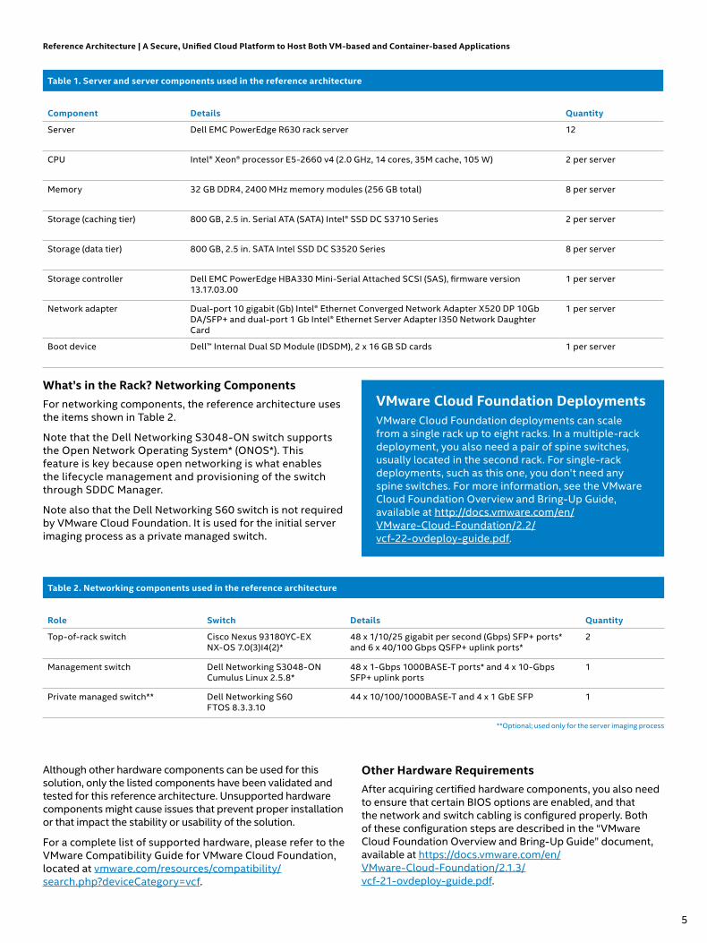
What’s in the Rack? Networking ComponentsFor networking components, the reference architecture uses the items shown in Table 2.
Note that the Dell Networking S3048-ON switch supports the Open Network Operating System* (ONOS*). This feature is key because open networking is what enables the lifecycle management and provisioning of the switch through SDDC Manager.
Note also that the Dell Networking S60 switch is not required by VMware Cloud Foundation. It is used for the initial server imaging process as a private managed switch.
VMware Cloud Foundation DeploymentsVMware Cloud Foundation deployments can scale from a single rack up to eight racks. In a multiple-rack deployment, you also need a pair of spine switches, usually located in the second rack. For single-rack deployments, such as this one, you don’t need any spine switches. For more information, see the VMware Cloud Foundation Overview and Bring-Up Guide, available at http://docs.vmware.com/en/ VMware-Cloud-Foundation/2.2/ vcf-22-ovdeploy-guide.pdf.
Reference Architecture | A Secure, Unified Cloud Platform to Host Both VM-based and Container-based Applications
Table 1. Server and server components used in the reference architecture
Component Details Quantity
Server Dell EMC PowerEdge R630 rack server 12
CPU Intel® Xeon® processor E5-2660 v4 (2.0 GHz, 14 cores, 35M cache, 105 W) 2 per server
Memory 32 GB DDR4, 2400 MHz memory modules (256 GB total) 8 per server
Storage (caching tier) 800 GB, 2.5 in. Serial ATA (SATA) Intel® SSD DC S3710 Series 2 per server
Storage (data tier) 800 GB, 2.5 in. SATA Intel SSD DC S3520 Series 8 per server
Storage controller Dell EMC PowerEdge HBA330 Mini-Serial Attached SCSI (SAS), firmware version 13.17.03.00
1 per server
Network adapter Dual-port 10 gigabit (Gb) Intel® Ethernet Converged Network Adapter X520 DP 10Gb DA/SFP+ and dual-port 1 Gb Intel® Ethernet Server Adapter I350 Network Daughter Card
1 per server
Boot device Dell™ Internal Dual SD Module (IDSDM), 2 x 16 GB SD cards 1 per server
Table 2. Networking components used in the reference architecture
Role Switch Details Quantity
Top-of-rack switch Cisco Nexus 93180YC-EX NX-OS 7.0(3)I4(2)*
48 x 1/10/25 gigabit per second (Gbps) SFP+ ports* and 6 x 40/100 Gbps QSFP+ uplink ports*
2
Management switch Dell Networking S3048-ON Cumulus Linux 2.5.8*
48 x 1-Gbps 1000BASE-T ports* and 4 x 10-Gbps SFP+ uplink ports
1
Private managed switch** Dell Networking S60 FTOS 8.3.3.10
44 x 10/100/1000BASE-T and 4 x 1 GbE SFP 1
**Optional; used only for the server imaging process
Although other hardware components can be used for this solution, only the listed components have been validated and tested for this reference architecture. Unsupported hardware components might cause issues that prevent proper installation or that impact the stability or usability of the solution.
For a complete list of supported hardware, please refer to the VMware Compatibility Guide for VMware Cloud Foundation, located at vmware.com/resources/compatibility/ search.php?deviceCategory=vcf.
Other Hardware RequirementsAfter acquiring certified hardware components, you also need to ensure that certain BIOS options are enabled, and that the network and switch cabling is configured properly. Both of these configuration steps are described in the “VMware Cloud Foundation Overview and Bring-Up Guide” document, available at https://docs.vmware.com/en/ VMware-Cloud-Foundation/2.1.3/ vcf-21-ovdeploy-guide.pdf.
5

Rack DiagramFigure 6 illustrates the placement in the rack of the hardware components that are required for this reference architecture.
configuration guidancEThe following sections describe the steps you need to take in order to build the solution after you have assembled the proper hardware in the rack, configured the cabling, and configured all required BIOS settings. Additionally, all disks should be empty and should not contain any partitions or user data.
Overview of the Configuration StepsThe configuration and deployment of the software stack involves three steps:
1. Installing and configuring VMware Cloud Foundation (including the workload domains)
2. Installing and configuring vSphere Integrated Containers
3. Containerizing applications
Installing and Configuring VMware Cloud FoundationTwo steps are required to install and configure VMware Cloud Foundation:
1. Image the hardware through the VMware Cloud Foundation imaging appliance (VIA). During this step, the appropriate software components and their initial configuration settings are loaded onto each server and switch, and a complete inventory of the hardware is built and saved.
2. Perform the bring-up process for VMware Cloud Foundation. During this step, the system is initialized, configured, and connected to the existing data center network.
Imaging the Hardware through the VMware Cloud Foundation Imaging Appliance (VIA)To complete this step, read the preparatory steps below, and then follow the instructions described in the “VIA User’s Guide” document, which you can find at https://docs.vmware.com/en/VMware-Cloud-Foundation/ 2.1.3/via-21-guide.pdf. As the document indicates, it is recommended that you install VIA on a desktop or laptop when you want to image a single rack.
To prepare for the procedure, ensure that the first network interface in each server has PXE support enabled. The boot sequence should also be configured in a way that the server first tries to boot from PXE, then from local SD card (IDSDM). The management switch must be in Open Network Install Environment* (ONIE*) install mode, ready for installation of the Cumulus Linux* operating system. The Cisco switches should contain no configuration and should be in the PowerOn Auto Provisioning (POAP) mode. Finally, all SD cards and SSDs should be empty. If the servers were previously used, these drives should be cleared of all data, because it could interfere with the imaging process.
During the imaging process, you can observe the progress of imaging each component and view detailed logs through the same web interface. In case of failure, you can restart the whole process for any specific device. Properly imaged devices will be marked with a green check mark.
Reference Architecture | A Secure, Unified Cloud Platform to Host Both VM-based and Container-based Applications
1 x Dell EMC Networking S3048-ON—Management Switch
2 x Cisco Nexus 93180YC-EX—Top-of-Rack Switches
12 x Dell EMC PowerEdge R630 (10x 2.5” SFF Hot-Plug Disks)—Compute Resources
• 2 x 14-core Intel® Xeon® processor E5-2660 v4, 2.0 GHz• 256 GB RAM (8 x 32 GB DIMMs)• Dell EMC PowerEdge RAID Controller HBA330• 2 x Intel® SSD DC S3710 Series (Cache)• 8 x Intel SSD DC S3520 Series (Capacity)• Dual-port 10 gigabit Ethernet (GbE) Intel® Ethernet Converged
Network Adapter X520 + 1 GbE Intel® Ethernet Server Adapter I350 Network Daughter Card (1 x 10 GbE in use)
• Dual-port 10 GbE Intel Ethernet Converged Network Adapter X520 PCIe* Networking Card (1 x 10 GbE in use)
• Dual redundant SD modules with 2 x 16 GB SD card (hypervisor)• Integrated Dell™ Remote Access Controller (iDRAC) Enterprise• Dell EMC™ OpenManage™ Essentials Server Configuration Management• Dual Redundant Hot-Plug Power Supplies (1+1) 750 W
Figure 6. A physical view of the components that make up the solution
6

Reference Architecture | A Secure, Unified Cloud Platform to Host both VM-based and Container-based Applications
Figure 7. The imaging process after completion
When the imaging process completes, VIA performs additional verification and uploads to the appropriate servers Secure Shell (SSH) keys, certificates, and the inventory database built during the imaging process.
The last step in the imaging process is to obtain the bootstrap passwords, including the password for the SDDC Manager VM (also called the VRM virtual machine), which will be needed later on during the bring-up process. The passwords are provided by VIA under the URL http://192.168.100.2:8080/via/ipsecThumbprint/runId, where runId is the run number. (VIA can be used for imaging multiple racks, in which case each imaging process is a separate run. You can find the run number or run ID in the top-left corner of Figure 7.)
Bring Up VMware Cloud FoundationOnce the imaging process is complete, you can move on to the second phase—bringing up VMware Cloud Foundation. The bring-up process is handled by SDDC Manager. A detailed explanation of this procedure is described in the “VMware Cloud Foundation Overview and Bring-Up Guide” document available at https://docs.vmware.com/en/ VMware-Cloud-Foundation/2.1.3/vcf-21-ovdeploy-guide.pdf. As with the VIA appliance, SDDC Manager is accessed through a standard web browser.
Before you start the bring-up process, first collect all the information needed to configure network connectivity, including a list of VLANs, network addresses, and uplinks.
When you access the SDDC Manager interface for the first time, the system automatically sets the proper time and time zone on all components. It also performs several basic checks to verify that all components are accessible and in the expected state.
Figure 8. A running log of the bring-up process
The next step of the bring-up process is to supply a new account name and password for the administrator account, in addition to some general information like a physical rack name, a root Domain Name System (DNS) domain name, the VMware Cloud Foundation subdomain, the SSO domain, and finally the VMware Cloud Foundation license key.
Figure 9. Entering basic information as part of the bring-up process
Reference Architecture | A Secure, Unified Cloud Platform to Host Both VM-based and Container-based Applications
7

Next is network configuration, where you provide VLAN and IP addresses for management, VMware vSphere® vMotion®, vSAN, a Virtual Extensible LAN (VXLAN) overlay, an external data center network, and data center uplinks.
Finally, there is a short summary page that displays all the information you have provided. This is followed by the Component IP Allocation page, which shows the names and IP addresses assigned to specific components.
Figure 10. Important IP address assignments are displayed at the end of the bring-up process
The Component IP Allocation page is important. Be sure to record the names and IP addresses listed for “vCenter” and “VRM VIP,” where SDDC Manager is running. These are the two main interfaces that you will use to manage the whole infrastructure.
The VRM VM also hosts the DNS server for the VMware Cloud Foundation sub-domain provided in an earlier step (in this example, vcf.example.com), so you should configure your enterprise DNS servers to forward all queries for that domain to the VRM VIP IP address.
After you click Confirm, SDDC Manager begins the configuration and bring-up process. This process can take up to an hour or two, depending on the number and configuration of servers. You can follow the progress of the bring-up process by using the same web interface.
One of the last steps in the bring-up process is to generate new passwords for all the components. To perform this step, you have to use SSH to connect to the VRM VM, and then run the following command: /home/vrack/bin/ vrm-cli.sh rotate-all. Next, use the same tool with the lookup-passwords argument to retrieve the newly generated passwords. This step will retrieve the passwords for all physical and logical components, including switches, servers, vCenter Server, and VMware NSX.
Creating Workload DomainsWhen the bring-up process completes, the infrastructure is ready for the creation of workload domains. In the current version of VMware Cloud Foundation, the first four
nodes are reserved for management purposes, and they contain all the components needed to manage the whole infrastructure. You should not deploy any user applications on this management cluster. Instead, you should create one or more workload domains that comprise a separate vSphere cluster with vSAN and VMware NSX pre-installed and configured along with a dedicated instance of vCenter Server for management purposes.
In addition to management domains, there are two other types of workload domains that can be created in SDDC Manager:
• Virtual infrastructure (VI): General purpose domain
• VDI: Dedicated to virtual desktop environments. These workload domains rely on VMware Horizon Suite, which is not part of this reference architecture.
The VI workload domain type represents a cluster of resources that can contain up to 64 servers with its own vCenter Server appliance, integrated vSAN, and VMware NSX. A VI workload domain can span multiple racks, so if you later add more racks to this single-rack implementation, you can scale any existing VI workload domains to the additional racks as needed.
All the tasks related to the workload domains are performed using the SDDC Manager web interface. This includes the creation, expansion, and deletion of workload domains, along with physical infrastructure monitoring and management.
Figure 11. SDDC Manager allows you to assign CPU, memory, and storage resources into workload domains
Creating a new workload domain is simple. After you provide the name, you need only to specify the required performance (low, balanced, or high), the desired availability level (none, normal, or high), and the minimum resources needed (for CPU, memory, and storage space). These settings are shown in Figure 12.
Reference Architecture | A Secure, Unified Cloud Platform to Host Both VM-based and Container-based Applications
8
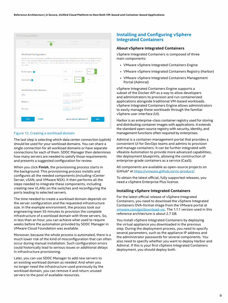
Figure 12. Creating a workload domain
The last step is selecting which data center connection (uplink) should be used for your workload domains. You can share a single connection for all workload domains or have separate connections for each of them. SDDC Manager then determines how many servers are needed to satisfy those requirements and presents a suggested configuration for review.
When you click Finish, the provisioning process starts in the background. This provisioning process installs and configures all the needed components (including vCenter Server, vSAN, and VMware NSX). It then performs all the steps needed to integrate these components, including creating new VLANs on the switches and reconfiguring the ports leading to selected servers.
The time needed to create a workload domain depends on the server configuration and the requested infrastructure size. In the example environment, the process took our engineering team 55 minutes to provision the complete infrastructure of a workload domain with three servers. So, in less than an hour, you can achieve what used to require weeks before the automation provided by SDDC Manager in VMware Cloud Foundation was available.
Moreover, because the whole process is automated, there is a much lower risk of the kind of misconfiguration that can often occur during manual installation. Such configuration errors could historically lead to serious issues or additional delays in infrastructure provisioning.
Later, you can use SDDC Manager to add new servers to an existing workload domain as needed. And when you no longer need the infrastructure used previously by the workload domain, you can remove it and return unused servers to the pool of available resources.
Installing and Configuring vSphere Integrated Containers
About vSphere Integrated ContainersvSphere Integrated Containers is composed of three main components:
• VMware vSphere Integrated Containers Engine
• VMware vSphere Integrated Containers Registry (Harbor)
• VMware vSphere Integrated Containers Management Portal (Admiral)
vSphere Integrated Containers Engine supports a subset of the Docker API as a way to allow developers and administrators to provision and run containerized applications alongside traditional VM-based workloads. vSphere Integrated Containers Engine allows administrators to easily manage these workloads through the familiar vSphere user interface (UI).
Harbor is an enterprise-class container registry used for storing and distributing container images with applications. It extends the standard open-source registry with security, identity, and management functions often required by enterprises.
Admiral is a container-management portal that provides a convenient UI for DevOps teams and admins to provision and manage containers. It can be further integrated with vRealize Automation to provide more advanced capabilities, like deployment blueprints, allowing the construction of enterprise-grade containers as a service (CaaS).
All components are available as open-source projects on GitHub* at https://vmware.github.io/vic-product/.
To obtain the latest official, fully supported releases, you need a vSphere Enterprise Plus license.
Installing vSphere Integrated ContainersFor the latest official release of vSphere Integrated Containers, you need to download the vSphere Integrated Containers OVA-format image from the VMware portal at vmware.com/go/download-vic. The 1.1.1 version used in this reference architecture is about 2.7 GB.
You install vSphere Integrated Containers by deploying the virtual appliance you downloaded in the previous step. During the deployment process, you need to specify several parameters, such as the appliance IP address and the administrator passwords for several components. You also need to specify whether you want to deploy Harbor and Admiral. If this is your first vSphere Integrated Containers deployment, you should deploy both.
Reference Architecture | A Secure, Unified Cloud Platform to Host Both VM-based and Container-based Applications
9

Figure 13. Configuration options for installing vSphere Integrated Containers
To complete the procedure for installing vSphere Integrated Containers, follow the detailed instructions found in the product documentation at the following address: https://vmware.github.io/vic-product/assets/files/html/1.1/
Because vSphere Integrated Containers is tightly coupled with vCenter Server, you need to deploy the appliance to the same workload domain where you want to run your workloads. Note that it doesn’t have to be a workload domain dedicated entirely to vSphere Integrated Containers; you can run traditional VMs and containers in the same workload domain next to each other with dedicated resources assigned to them.
This is a key feature of vSphere Integrated Containers: to enable admins and developers to create and manage containers in a way that is fully integrated into their VM infrastructure. Running both workloads together, in fact, allows deployment of hybrid multi-tier applications where some components run as VMs and others run in easily scalable containers.
Unpacking vSphere Integrated Containers BinariesThe next step in installing vSphere Integrated Containers is to download and unpack the vSphere Integrated Containers Engine binaries from https://vic_appliance_address:9443 to an administrator’s workstation. This package contains the vic-machine utility, which is used to deploy virtual container hosts (VCHs). You can also use the vSphere Web Client Integration Plugin to enable unified management of containers and vSphere resources, including VMs.
To unpack the vSphere Integrated Containers Engine binaries, enter the command on the first line to the right (which is followed by output):
Reference Architecture | A Secure, Unified Cloud Platform to Host Both VM-based and Container-based Applications
(continued on next page)
admin@localhost ~ $ curl -O -k https://172.16.0.100:9443/vic _ 1.1.1.tar.gz % Total % Received % Xferd Average Speed Time Time Time Current Dload Upload Total Spent Left Speed100 223M 100 223M 0 0 193M 0 0:00:01 0:00:01 --:--:-- 193M
admin@localhost ~ $ ls -ltotal 229076-rw-r--r--. 1 admin admin 234566550 Aug 8 13:48 vic _ 1.1.1.tar.gz
admin@localhost ~ $ tar zxvf vic _ 1.1.1.tar.gzvic/vic/vic-machine-windows.exevic/vic-ui-darwinvic/appliance.isovic/READMEvic/bootstrap.isovic/vic-machine-darwinvic/vic-ui-linuxvic/ui/vic/ui/plugin-manifestvic/ui/VCSA/vic/ui/VCSA/configsvic/ui/VCSA/install.shvic/ui/VCSA/upgrade.shvic/ui/VCSA/uninstall.shvic/ui/plugin-packages/vic/ui/plugin-packages/com.vmware.vic-v1.1.1.zipvic/ui/plugin-packages/com.vmware.vic-v1.1.1/vic/ui/plugin-packages/com.vmware.vic-v1.1.1/plugins/vic/ui/plugin-packages/com.vmware.vic-v1.1.1/plugins/vlsiCore.jarvic/ui/plugin-packages/com.vmware.vic-v1.1.1/plugins/vim25.jarvic/ui/plugin-packages/com.vmware.vic-v1.1.1/plugins/gson-2.3.1.jarvic/ui/plugin-packages/com.vmware.vic-v1.1.1/plugins/vic-service.jarvic/ui/plugin-packages/com.vmware.vic-v1.1.1/plugins/vic.warvic/ui/plugin-packages/com.vmware.vic-v1.1.1/plugin-package.xmlvic/ui/vCenterForWindows/
10

Understanding the vSphere Integrated Containers WorkflowvSphere Integrated Containers Engine is an enterprise deployment target for portable Docker containers. The following steps make up the typical workflow for using vSphere Integrated Containers:
1. Developers build containers in their development environments by using either a local Docker host or a remote Docker endpoint provided by vSphere Integrated Containers.
2. A built container image is then pushed to the private enterprise registry, provided by Harbor.
3. The application can be deployed from the registry to test separate environments.
4. Finally, the application is deployed from the registry to a production environment that is also running vSphere Integrated Containers Engine on top of vSphere.
Understanding Virtual Container HostsA VCH is a resource pool that is mapped to an endpoint VM and that acts as a Docker host in vSphere Integrated Containers. From a management perspective, a VCH looks very similar to a VM that hosts Docker containers, and containers
appear to run within specific VCHs. More specifically, a VCH is deployed as a virtual application (vApp) in a vSphere cluster, and all VMs running containers are represented as children of a specific VCH in the user interface.
From a technical perspective, however, VCHs do not truly host containers by providing a shared kernel or OS upon which containers run. Instead, an endpoint VM representing a VCH runs side by side with containers, which all run within their own VMs called “container VMs.” Each container VM—and the endpoint VM itself—runs a minimal, quick-booting OS, called Photon OS™.
The Docker API endpoint that runs in the VCH translates Docker commands to the vSphere environment. For example, when the Docker endpoint receives Docker commands such as “run” and “build,” the VCH instructs the vCenter Server to create a VM running the Photon OS kernel and to unpack the Docker image into that VM. Other commands are translated and executed against the containers of the VCH.
A VCH is easy to scale as a resource pool. To do so, just add an ESXi host to the workload vSphere cluster to increase the capacity without disrupting the existing containers. You can also deploy multiple VCHs in the same cluster. Doing so allows you to easily provide fully separated and secure environments for multiple tenants sharing the same underlying infrastructure.
To create and configure a VCH, use the vic-machine command-line utility.
Reference Architecture | A Secure, Unified Cloud Platform to Host Both VM-based and Container-based Applications
vic/ui/vCenterForWindows/upgrade.batvic/ui/vCenterForWindows/uninstall.batvic/ui/vCenterForWindows/configsvic/ui/vCenterForWindows/install.batvic/ui/vsphere-client-serenity/vic/ui/vsphere-client-serenity/com.vmware.vic.ui-v1.1.1.zipvic/ui/vsphere-client-serenity/com.vmware.vic.ui-v1.1.1/vic/ui/vsphere-client-serenity/com.vmware.vic.ui-v1.1.1/plugins/vic/ui/vsphere-client-serenity/com.vmware.vic.ui-v1.1.1/plugins/vic-ui-service.jarvic/ui/vsphere-client-serenity/com.vmware.vic.ui-v1.1.1/plugins/vim25.jarvic/ui/vsphere-client-serenity/com.vmware.vic.ui-v1.1.1/plugins/vic-ui-war.warvic/ui/vsphere-client-serenity/com.vmware.vic.ui-v1.1.1/plugin-package.xmlvic/LICENSEvic/vic-machine-linuxvic/vic-ui-windows.exe
admin@localhost ~ $ cd vicadmin@localhost ~/vic $ ln vic-machine-linux vic-machine
admin@localhost ~/vic ./vic-machineNAME: vic-machine - Create and manage Virtual Container Hosts
USAGE: vic-machine [global options] command [command options] [arguments...]
VERSION: v1.1.1-10711-56a309f
COMMANDS: create Deploy VCH delete Delete VCH and associated resources ls List VCHs inspect Inspect VCH upgrade Upgrade VCH to latest version version Show VIC version information debug Debug VCH update Modify configuration help, h Shows a list of commands or help for one command
GLOBAL OPTIONS: --help, -h show help --version, -v print the version
11

Figure 14 depicts the relationship between the various vSphere Integrated Containers components. In the figure, A1 and A2 represent Docker endpoints, and C1, C2, and C3 represent container VMs.
VMware vCenter®
A1 C1 C3 C2
C1 A2
VIC Appliance
VMware ESXi™ VMware ESXi™ VMware ESXi™
ManagesContainers Manages VCHs
To VMware vCenter® SDK
AdminMonitoring
Docker*Client
VICMachine
VMware vCenter®
Client
Browser Docker*Client
VICAdmin(logs, debug)
Dockerpersonality
Port Layer Services(exec, net, storage, event, interact)
Figure 14. Relationship between VMware vSphere Integrated Containers Engine components1
Network TypesThe vSphere Integrated Containers Engine uses different network types for different purposes:
1. Management network: This network is dedicated to communication between the VCH, vCenter Server, and ESXi hosts. You define the management network by using the --management-network option when you create the VCH with vic-machine create.
2. Public network: This network, which is mandatory, connects containers to the Internet. You specify the public network with the --public-network option.
3. Client network: This network connects Docker clients to Docker endpoints and isolates the endpoints from the public network. You define the Docker management endpoint network by setting the --client-network option.
4. Bridge network: This network allows the containers and the VCH to communicate with each other. Each VCH requires a unique bridge network. To specify the bridge network, use the --bridge-network option when you run vic-machine create.
5. Container network: This type of network is used to connect containers directly to vSphere networks without routing through the VCH endpoint VM using NAT.
Figure 15 illustrates the roles of these different network types.
VCH vApp
PublicNetwork
BridgeNetwork
ContainerNetwork
User
Developer
VMware vSphere®/VMware ESXi™
Container-VM
Container-VM
Container-VM
ManagementPortal Registry
VMware vSphere® Integrated Containers™ Appliance
ClientNetwork
ManagementNetwork VCH
EndpointVM
Figure 15. Network types and roles1
When you define a network for vSphere Integrated Containers, you must specify a port group to associate with the networks you define. Most of the needed port groups for the VMware Cloud Foundation networks that we will define in this reference architecture have been created as part of the imaging process.
For this reference architecture, we will specify a management, public, bridge, and container network when we create the VCH, but we will not define any client networks. (When no client networks are defined, the default network used for this purpose is the same as the public network.)
For more information about virtual networks used with vSphere Integrated Containers, visit https://vmware.github.io/vic-product/assets/files/html/1.1/vic_vsphere_admin/networks.html .
Preparing for VCH DeploymentBefore we create the VCH by using the vic-machine utility, we need to perform some preparatory steps, such as creating a logical switch in VMware NSX for the bridge network and modifying firewall rules.
Creating a Logical Switch for the Bridge NetworkThe four networks we define when we create the VCH must all be assigned port groups. Of the port groups we will assign, only the port group for the bridge network has not yet been created. (The vRack-DPortGroup-External and vRack-DPortGroup-Mgmt port groups are created and configured automatically during workload domain creation by SDDC Manager.)
However, instead of creating that new port group in vSphere, we will create a logical switch in VMware NSX to assign to the bridge network. We specifically use the Logical Switch feature of VMware NSX (instead of vSphere port groups) in order to take advantage of overlay networking and avoid having to configure any VLANs on the physical switches.
Reference Architecture | A Secure, Unified Cloud Platform to Host Both VM-based and Container-based Applications
12

To create the new logical switch in the vSphere Web Client interface, navigate to Networking & Security, and then Logical Switches. To begin the process of creating a new logical switch, click the green plus (+) icon. This step opens the New Logical Switch window shown in Figure 16.
Figure 16. Creating a new logical switch
From the vSphere perspective, the new logical switch “VCH1-BRIDGE,” created in VMware NSX, is visible as a distributed port group with a name like vxw-dvs-9-virtualwire-2-10001-VCH1-BRIDGE. For simplicity, you might prefer to rename the port group to the name used for the associated logical switch in VMware NSX (as shown in Figure 17).
Although we have now created the port group to assign to the bridge network, we will create that bridge network later, when we create the VCH. At that time we will specify this port group by its new name, VCH1-BRIDGE.
Figure 17. Renaming the port group in VMware vSphere to match the VMware NSX logical switch name (optional)
Determining VCH Storage and Compute ResourcesWhen you use the vic-machine utility to create the VCH, you will need to specify a volume store, image store, and compute resource. For the volume store, we will use vsanDatastore/vic-containers:default. For the image store, we will specify vsanDatastore/vic-images. The compute resource can be a host, cluster, or resource pool. In our case, we will specify the compute resource as VCH.
Setting Up the PKIIn production environments, you should deploy valid public-key infrastructure (PKI) certificates to infrastructure components. (For instructions on how to perform this step, use the documentation accompanying your chosen PKI solution.) As a workaround, you can skip certificate validation by using the --no-tlsverify and --force options. In this case, however, you must specify the Secure Hash Algorithm 1 (SHA-1) thumbprint of the vCenter Server certificate with the --thumbprint option. (This thumbprint can be obtained by inspecting the certificate in a web browser or by first attempting to run the command without the --thumbprint option. Failing to provide this option will generate an error message that includes the retrieved thumbprint of your vCenter Server).
For other, more advanced deployment scenarios, please refer to vSphere Integrated Containers documentation at https://vmware.github.io/vic-product/assets/files/html/1.1/.
Modifying Firewall RulesThe next step required is modifying firewall rules on all ESXi hosts in the cluster to enable outgoing traffic from each host to the VCH. To perform this step, run the following command (which appears on the first three lines below, followed by output), substituting the SHA-1 thumbprint of your own vCenter Server certificate:
Reference Architecture | A Secure, Unified Cloud Platform to Host Both VM-based and Container-based Applications
admin@localhost ~/vic $ ./vic-machine update firewall --allow --target rack-1-vc-2.vcf.example.com \ --user [email protected] --password P@ssw0rd \ --thumbprint 59:73:5A:C7:BB:B6:02:57:35:D9:4A:9A:6B:9F:51:68:DD:A8:31:BCAug 9 2017 14:18:34.000Z INFO ### Updating Firewall ####Aug 9 2017 14:18:34.112Z INFO Validating targetAug 9 2017 14:18:34.112Z INFO Validating compute resourceAug 9 2017 14:18:34.112Z INFOAug 9 2017 14:18:34.112Z WARN ### WARNING ###Aug 9 2017 14:18:34.112Z WARN This command modifies the host firewall on the target machine or clusterAug 9 2017 14:18:34.112Z WARN The ruleset “vSPC” will be enabledAug 9 2017 14:18:34.112Z WARN This allows all outbound TCP traffic from the targetAug 9 2017 14:18:34.112Z WARN To undo this modification use --denyAug 9 2017 14:18:34.112Z INFOAug 9 2017 14:18:34.151Z INFO Ruleset “vSPC” enabled on host “HostSystem:host-20 @ /vRack-Datacenter/host/WD1-0-cluster/172.17.0.25”Aug 9 2017 14:18:34.185Z INFO Ruleset “vSPC” enabled on host “HostSystem:host-26 @ /vRack-Datacenter/host/WD1-0-cluster/172.17.0.26”Aug 9 2017 14:18:34.217Z INFO Ruleset “vSPC” enabled on host “HostSystem:host-30 @ /vRack-Datacenter/host/WD1-0-cluster/172.17.0.27”Aug 9 2017 14:18:34.248Z INFO Ruleset “vSPC” enabled on host “HostSystem:host-72 @ /vRack-Datacenter/host/WD1-0-cluster/172.17.0.42”Aug 9 2017 14:18:34.248Z INFOAug 9 2017 14:18:34.248Z INFO Firewall changes completeAug 9 2017 14:18:34.249Z INFO Command completed successfully
13

In addition, because we are going to secure the internal container registry (Harbor), we need to obtain the certificate authority (CA) certificate used to sign the default self-signed certificate used by Harbor and then provide it as a parameter to the VCH. To complete this step, enter the command on the first line below (which appears followed by output):
admin@localhost ~/vic $ scp [email protected]:/data/
harbor/cert/ca.crt ca.crt
The authenticity of host ‘vic.example.com (172.16.0.100)’
can’t be established.
ECDSA key fingerprint is SHA256:CRG5YlPQVu9UVwD8IOxrWFOniUA
QJh6BRjXIeFKCMR0.
Are you sure you want to continue connecting (yes/no)?
yes
Warning: Permanently added ‘vic.example.com,172.16.0.100’
(ECDSA) to the list of known hosts.
Password:
ca.crt
Increasing the Memory Reserved for the VCHThe current version (1.1.1) of vSphere Integrated Containers has a particular limitation: in the process of pulling container images from the registry, a service on the VCH extracts its contents to a temporary file system held in memory (tmpfs). For large containers, this process might fail if there is not enough free space. To handle large images properly in version 1.1.1, we need to increase the memory reservation for VCH by adding special parameter --endpoint-memory 8192 to the vic-machine create command.
Creating a VCHFinally, you can deploy a new VCH by using the vic-machine create command. Remember, in production environments you should deploy valid PKI certificates to infrastructure components. Again, as a workaround, you can skip certificate validation by using the --no-tlsverify and --force options and specifying a thumbprint instead with the --thumbprint option.
Run the following command (which appears on the first 15 lines below, followed by output) to create the VCH:
Reference Architecture | A Secure, Unified Cloud Platform to Host Both VM-based and Container-based Applications
(continued on next page)
admin@localhost ~/vic $ ./vic-machine create --target rack-1-vc-2.vcf.example.com \--user [email protected] --password P@ssw0rd \--thumbprint 59:73:5A:C7:BB:B6:02:57:35:D9:4A:9A:6B:9F:51:68:DD:A8:31:BC --name VCH1 \--compute-resource VCH --image-store vsanDatastore/vic-images \--volume-store vsanDatastore/vic-containers:default --bridge-network VCH1-BRIDGE \--bridge-network-range 192.168.0.0/16 --public-network vRack-DPortGroup-External \--management-network vRack-DPortGroup-Mgmt --container-network vRack-DPortGroup-External \--registry-ca=ca.crt --no-tlsverify --force --endpoint-memory 8192 Aug 9 2017 15:07:21.055Z INFO ### Installing VCH ####Aug 9 2017 15:07:21.055Z WARN Using administrative user for VCH operation - use --ops-user to improve security (see -x for advanced help)Aug 9 2017 15:07:21.057Z INFO Loaded server certificate VCH1/server-cert.pemAug 9 2017 15:07:21.057Z WARN Configuring without TLS verify - certificate-based authentication disabledAug 9 2017 15:07:21.057Z INFO Loaded registry CA from ca.crtAug 9 2017 15:07:21.155Z INFO Validating supplied configurationAug 9 2017 15:07:21.260Z INFO vDS configuration OK on “VCH1-BRIDGE”Aug 9 2017 15:07:21.266Z INFO vDS configuration OK on “vRack-DPortGroup-External”Aug 9 2017 15:07:21.292Z INFO Firewall status: ENABLED on “/vRack-Datacenter/host/WD1-0-cluster/172.17.0.25”Aug 9 2017 15:07:21.309Z INFO Firewall status: ENABLED on “/vRack-Datacenter/host/WD1-0-cluster/172.17.0.26”Aug 9 2017 15:07:21.327Z INFO Firewall status: ENABLED on “/vRack-Datacenter/host/WD1-0-cluster/172.17.0.27”Aug 9 2017 15:07:21.344Z INFO Firewall status: ENABLED on “/vRack-Datacenter/host/WD1-0-cluster/172.17.0.42”Aug 9 2017 15:07:21.352Z INFO Firewall configuration OK on hosts:Aug 9 2017 15:07:21.352Z INFO “/vRack-Datacenter/host/WD1-0-cluster/172.17.0.25”Aug 9 2017 15:07:21.352Z INFO “/vRack-Datacenter/host/WD1-0-cluster/172.17.0.26”Aug 9 2017 15:07:21.352Z INFO “/vRack-Datacenter/host/WD1-0-cluster/172.17.0.27”Aug 9 2017 15:07:21.352Z INFO “/vRack-Datacenter/host/WD1-0-cluster/172.17.0.42”Aug 9 2017 15:07:21.403Z INFO License check OK on hosts:Aug 9 2017 15:07:21.403Z INFO “/vRack-Datacenter/host/WD1-0-cluster/172.17.0.25”Aug 9 2017 15:07:21.403Z INFO “/vRack-Datacenter/host/WD1-0-cluster/172.17.0.26”Aug 9 2017 15:07:21.403Z INFO “/vRack-Datacenter/host/WD1-0-cluster/172.17.0.27”Aug 9 2017 15:07:21.403Z INFO “/vRack-Datacenter/host/WD1-0-cluster/172.17.0.42”Aug 9 2017 15:07:21.421Z INFO DRS check OK on:Aug 9 2017 15:07:21.421Z INFO “/vRack-Datacenter/host/WD1-0-cluster”Aug 9 2017 15:07:21.454Z INFOAug 9 2017 15:07:21.593Z INFO Creating virtual app “VCH1”Aug 9 2017 15:07:21.635Z INFO Creating directory [vsanDatastore] vic-containersAug 9 2017 15:07:21.726Z INFO Datastore path is [vsanDatastore] vic-containersAug 9 2017 15:07:21.726Z INFO Creating appliance on targetAug 9 2017 15:07:21.731Z INFO Network role “client” is sharing NIC with “public”Aug 9 2017 15:07:25.922Z INFO Uploading images for containerAug 9 2017 15:07:25.922Z INFO “bootstrap.iso”Aug 9 2017 15:07:25.922Z INFO “appliance.iso”Aug 9 2017 15:07:31.422Z INFO Waiting for IP informationAug 9 2017 15:07:46.594Z INFO Waiting for major appliance components to launchAug 9 2017 15:07:46.635Z INFO Obtained IP address for client interface: “172.16.50.28”Aug 9 2017 15:07:46.635Z INFO Checking VCH connectivity with vSphere targetAug 9 2017 15:07:46.731Z INFO vSphere API Test: https://rack-1-vc-2.vcf.example.com vSphere API target responds as expectedAug 9 2017 15:07:48.751Z INFO Initialization of appliance successfulAug 9 2017 15:07:48.751Z INFOAug 9 2017 15:07:48.751Z INFO VCH Admin Portal:
14
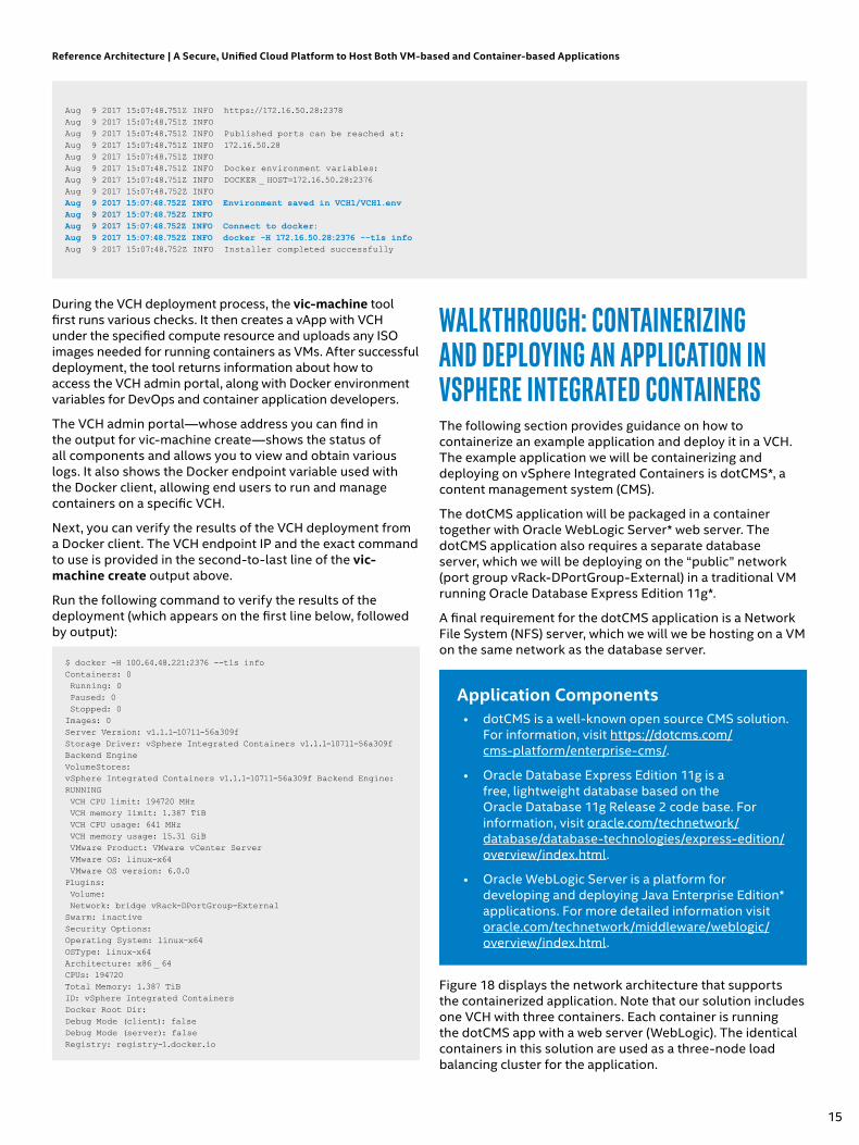
During the VCH deployment process, the vic-machine tool first runs various checks. It then creates a vApp with VCH under the specified compute resource and uploads any ISO images needed for running containers as VMs. After successful deployment, the tool returns information about how to access the VCH admin portal, along with Docker environment variables for DevOps and container application developers.
The VCH admin portal—whose address you can find in the output for vic-machine create—shows the status of all components and allows you to view and obtain various logs. It also shows the Docker endpoint variable used with the Docker client, allowing end users to run and manage containers on a specific VCH.
Next, you can verify the results of the VCH deployment from a Docker client. The VCH endpoint IP and the exact command to use is provided in the second-to-last line of the vic-machine create output above.
Run the following command to verify the results of the deployment (which appears on the first line below, followed by output):
$ docker -H 100.64.48.221:2376 --tls infoContainers: 0 Running: 0 Paused: 0 Stopped: 0Images: 0Server Version: v1.1.1-10711-56a309fStorage Driver: vSphere Integrated Containers v1.1.1-10711-56a309f Backend EngineVolumeStores:vSphere Integrated Containers v1.1.1-10711-56a309f Backend Engine: RUNNING VCH CPU limit: 194720 MHz VCH memory limit: 1.387 TiB VCH CPU usage: 641 MHz VCH memory usage: 15.31 GiB VMware Product: VMware vCenter Server VMware OS: linux-x64 VMware OS version: 6.0.0Plugins: Volume: Network: bridge vRack-DPortGroup-ExternalSwarm: inactiveSecurity Options:Operating System: linux-x64OSType: linux-x64Architecture: x86 _ 64CPUs: 194720Total Memory: 1.387 TiBID: vSphere Integrated ContainersDocker Root Dir:Debug Mode (client): falseDebug Mode (server): falseRegistry: registry-1.docker.io
Walkthrough: containErizing and dEPloying an aPPlication in vSPhErE intEgratEd containErSThe following section provides guidance on how to containerize an example application and deploy it in a VCH. The example application we will be containerizing and deploying on vSphere Integrated Containers is dotCMS*, a content management system (CMS).
The dotCMS application will be packaged in a container together with Oracle WebLogic Server* web server. The dotCMS application also requires a separate database server, which we will be deploying on the “public” network (port group vRack-DPortGroup-External) in a traditional VM running Oracle Database Express Edition 11g*.
A final requirement for the dotCMS application is a Network File System (NFS) server, which we will we be hosting on a VM on the same network as the database server.
Application Components• dotCMS is a well-known open source CMS solution.
For information, visit https://dotcms.com/ cms-platform/enterprise-cms/.
• Oracle Database Express Edition 11g is a free, lightweight database based on the Oracle Database 11g Release 2 code base. For information, visit oracle.com/technetwork/database/database-technologies/express-edition/overview/index.html.
• Oracle WebLogic Server is a platform for developing and deploying Java Enterprise Edition* applications. For more detailed information visit oracle.com/technetwork/middleware/weblogic/overview/index.html.
Figure 18 displays the network architecture that supports the containerized application. Note that our solution includes one VCH with three containers. Each container is running the dotCMS app with a web server (WebLogic). The identical containers in this solution are used as a three-node load balancing cluster for the application.
Reference Architecture | A Secure, Unified Cloud Platform to Host Both VM-based and Container-based Applications
Aug 9 2017 15:07:48.751Z INFO https://172.16.50.28:2378Aug 9 2017 15:07:48.751Z INFOAug 9 2017 15:07:48.751Z INFO Published ports can be reached at:Aug 9 2017 15:07:48.751Z INFO 172.16.50.28Aug 9 2017 15:07:48.751Z INFOAug 9 2017 15:07:48.751Z INFO Docker environment variables:Aug 9 2017 15:07:48.751Z INFO DOCKER _ HOST=172.16.50.28:2376Aug 9 2017 15:07:48.752Z INFOAug 9 2017 15:07:48.752Z INFO Environment saved in VCH1/VCH1.envAug 9 2017 15:07:48.752Z INFOAug 9 2017 15:07:48.752Z INFO Connect to docker:Aug 9 2017 15:07:48.752Z INFO docker -H 172.16.50.28:2376 --tls infoAug 9 2017 15:07:48.752Z INFO Installer completed successfully
15
http://www.oracle.com/technetwork/database/database-technologies/express-edition/overview/index.html
http://www.oracle.com/technetwork/database/database-technologies/express-edition/overview/index.html

Load Balancer( VMware NSX® Edge™)
External networkwith internet access
NFSServer(VM)
Database(VM)
Distributed firewall–microsegmentation (VMware NSX®)
vRack-DPortGroup-External
DHCP(external)
DNS(external)
VCH1
APP and Oracle
WebLogic Server*
APP and Oracle
WebLogic Server*
APP and Oracle
WebLogic Server*
Figure 18. The network architecture supporting the containerized application
Outside of the VCH, a database server and an NFS server, which are both needed by dotCMS, are running separately on their own VMs. The solution also includes a load balancer (VMware NSX® Edge™) to split requests among all three container-VMs hosting dotCMS. Finally, a distributed firewall is deployed through NSX.
Overview of the Deployment ProcedureTo deploy the containerized application, we will first deploy the supporting database and NFS servers on the network. Next, we’ll build and upload the container image. Finally, we’ll deploy the dotCMS cluster and configure the dotCMS application.
The deployment procedure can be divided into the following steps:
1. Deploy and configure the database server.2. Set up the NFS server for the application.3. Build the WebLogic and dotCMS container image.4. Upload the image to the container registry.5. Deploy the dotCMS cluster.6. Configure the dotCMS application.
To perform the deployment steps described below, you need access to an Internet-connected GNU/Linux workstation with a Bash* shell. In addition, you need to make the following applications available on your Linux workstation before you begin:
• Git* for downloading Oracle’s GitHub* repository• Docker for building Docker images and for
communication with VIC• Java Development Kit* (JDK*) for building dotCMS• A text editor
The following conventions are used in our presentation of command-line commands:
$: Run the command as an unprivileged user in Bash#: Run the command as the user “root” in Bash>: Run the command as the user “system” in SQL*Plus*
Deploy and Configure the Database Server1. Create a new VM on VMware Cloud Foundation and
install a Red Hat* Enterprise Linux 7.x* OS. You should assign the VM at least two virtual CPUs, 4 GB RAM, and 200 GB of hard-disk space, as shown in Figure 19. For more detailed information about the requirements for the database server, refer to the official Oracle documentation at http://docs.oracle.com/cd/E17781_01/install.112/e18802/toc.htm#XEINL102
Figure 19. Creating a new VM in vSphere Web Client
2. Assign a static IP address to the VM and provide a full DNS name. For example, we set the IP address to 172.16.200.200 and the full DNS name to oracledb1.example.com. After setting the DNS name, we also need to configure a hostname in the VM: # echo oracledb1.example.com > /etc/hostname
3. Restart the VM.
4. Download Oracle Database Express Edition 11g from oracle.com/technetwork/database/database-technologies/express-edition/downloads/index.html. Note that you will have to create an Oracle account first.
5. Install the Oracle Database dependencies: $ sudo yum install -y bc libaio
6. Unpack and install the rpm file: $ sudo rpm -i Disk1/oracle-xe-11.2.0-1.0.x86 _ 64.rpm
7. Configure the database instance: $ sudo /etc/init.d/oracle-xe configure You will be asked about database-related options. Default values will suffice. You need to set only the administrator’s password.
8. Export environment variables for use with database management tools: $ . /u01/app/oracle/product/11.2.0/xe/bin/ oracle _ env.sh
9. Once the database instance has started successfully, run following commands in terminal: $ sqlplus system After you type the password chosen in step 7, the SQL console should be available.
Reference Architecture | A Secure, Unified Cloud Platform to Host Both VM-based and Container-based Applications
16

10. (Optional) Enter the following commands to configure web interface:
$ cd /u01/app/oracle/product/11.2.0/xe/apex$ sqlplus system> @apxconf> alter user anonymous account unlock;
Running the “@apxconf” script will result in a query for the web interface parameters. The default values are sufficient; only the “ADMIN” password needs to be set explicitly. After completing these steps, the web interface will be available over HTTP at the VM’s static IP address at port 8080, followed by “/apex.” For example, the web interface address for the IP address of 172.16.200.200 is http://172.16.200.200:8080/apex.
Figure 20. The database server web administration interface
11. Create a new user and give the user appropriate permissions for dotCMS. In sqlplus, type the following (where “XXXXXXXX” is the password in quotations you want to set for new user):
CREATE USER “DOTCMS _ SENDER” PROFILE “DEFAULT” IDENTIFIED BY “XXXXXXXX” ACCOUNT UNLOCK;GRANT “CONNECT” TO “DOTCMS _ SENDER”;GRANT “EXP _ FULL _ DATABASE” TO “DOTCMS _ SENDER”;GRANT “GATHER _ SYSTEM _ STATISTICS” TO “DOTCMS _SENDER”;GRANT “IMP _ FULL _ DATABASE” TO “DOTCMS _ SENDER”;GRANT “OEM _ ADVISOR” TO “DOTCMS _ SENDER”;GRANT “OEM _ MONITOR” TO “DOTCMS _ SENDER”;GRANT “RESOURCE” TO “DOTCMS _ SENDER”;ALTER USER “DOTCMS _ SENDER” DEFAULT ROLE ALL;EXIT
12. Open ports on the firewall:
$ sudo firewall-cmd --get-active-zonespublic interfaces: ens192$ sudo firewall-cmd --zone=public --add-port=1521/tcp --add-port=8080/tcp \--permanentsuccess$ sudo firewall-cmd --reloadsuccess$ sudo firewall-cmd --list-ports1521/tcp 8080/tcp
For more information on installing Oracle Database Express Edition 11g and configuring an account for dotCMS, please refer to official documentation at the following addresses:
• http://docs.oracle.com/cd/E17781_01/index.htm
• https://dotcms.com/docs/latest/ database-configuration#Oracle
Setting Up the NFS ServerOur dotCMS implementation consists of a cluster of three containers. Clustering dotCMS requires a network share external to the cluster that shares out the contents of the asset directory to all container nodes. The easiest way to provide such a network share is to set up an NFS server instance, export one directory, and then mount that directory in each container running dotCMS.
For our NFS server, we are using a VM running CoreOS Container Linux*, but you can use any Linux distribution of your choice, and then follow the documentation describing the process for setting up an NFS server.
At this point, we will proceed under the assumption that you have already deployed CoreOS in a VM and that it already has network connectivity properly configured (either using Dynamic Host Configuration Protocol [DHCP] or a static IP address assignment). You should also register your server in DNS so you can use a domain name instead of an IP address in a container image. In our environment, we will assign our NFS server an IP address of 172.16.255.99 and a domain name of nfs.example.com.
To set up an NFS server on CoreOS Container Linux, you need to create a new directory named nfs, modify the /etc/exports file to export that directory to the 172.16.0.0/16 network with read-write permission, and finally enable and start the nfsd daemon.
You perform those steps with the following commands:
core@nfs ~ $ sudo -infs ~ # mkdir /nfsnfs ~ # echo ”/nfs 172.16.0.0/16(rw)” >> /etc/exportsnfs ~ # systemctl enable nfsdnfs ~ # systemctl start nfsd
You can verify the status of the daemon using the systemctl status nfsd command, and you can list exported directories using the exportfs -v command.
nfs ~ # exportfs -v/nfs 172.16.0.0/16(rw,wdelay,root _ squash,no _subtree _ check,sec=sys,rw,secure,root _ squash,no _ all _squash)
After the NFS server is running, you will later mount the exported directory on the client by specifying the following network path: nfs.example.com:/nfs
Reference Architecture | A Secure, Unified Cloud Platform to Host Both VM-based and Container-based Applications
17

Building an Oracle WebLogic Server and dotCMS* Container Image1. Get the Oracle Docker images from GitHub:
$ git clone https://github.com/oracle/docker-images oracle-docker-images$ git checkout 7db020b25ea9d603b2fa97ed850ef4b372c1821e
We are checking out a specific revision (available at the time of this writing) to ensure that the following steps are reproducible.
2. From oracle.com/technetwork/java/javase/downloads/index-jsp-138363.html, download the latest Oracle Server JRE* for GNU/Linux x64 to oracle-docker-images/OracleJava/java-8/.
3. In the directory oracle-docker-images/OracleJava/java-8 build an image with Server JRE: $ ./build.sh
4. Change the active directory to oracle-docker-images/OracleWebLogic/dockerfiles/12.2.1.2.
5. Download fmw_12.2.1.2.0_wls_quick_Disk1_1of1.zip from oracle.com/technetwork/middleware/weblogic/downloads/wls-for-dev-1703574.html, and then put the file into the directory oracle-docker-images/OracleWebLogic/dockerfiles/12.2.1.2.
6. Build the base WebLogic image. In the directory oracle-docker-images/OracleWebLogic/dockerfiles/, run the following command: $ ./buildDockerImage.sh -v 12.2.1.2 -g
7. From the address https://dotcms.com/download/, download the dotCMS package.
8. Decompress dotCMS*.tar.gz into a separate folder and build the application:
$ cd$ mkdir dotCMS && cd dotCMS$ tar xf ~/<download location>/dotCMS*tar.gz$ bin/buildwar.sh
9. Create the directory that will hold installation scripts and the Docker file.
$ cd $ mkdir wl _ dotCMS
10. Unpack dotCMS.war to wl_dotCMS:
$ unzip $HOME/dotCMS/WAR/dotcms.war -d wl _ dotCMS/dotcms.war
11. At the end of the file wl_dotCMS/dotcms.war/WEB-INF/classes/dotmarketing-config.properties, add the following line:
QUARTZ _ DRIVER _ CLASS=org.quartz.impl.jdbcjobstore.oracle.weblogic.WebLogicOracleDelegate
This line enables support for WebLogic in dotCMS. It is not required, but it is recommended by dotCMS developers.
12. In the file wl_dotCMS/dotcms.war/WEB-INF/classes/dotcms-config-cluster.properties, change line 132 from “es.discovery.zen.fd.ping_timeout=600s” to “es.discovery.zen.fd.ping_timeout=10s”. This change will reduce the time that dotCMS instances will wait for each other in the cluster in case one of the dotCMS hosts fails. Next, we will use sample scripts prepared by Oracle in our deployment process. They provide a good base for deployment and, with only a few modifications, will perfectly suit our needs.
13. Copy the files from the directory oracle-docker-images/OracleWebLogic/samples/12212-domain/container-scripts to wl_dotCMS/container-scripts and the file oracle-docker-images/OracleWebLogic/samples/1221-appdeploy/container-scripts/app-deploy.py to wl_dotCMS/container-scripts/. The scripts from 12212-domain will simplify the process of creating the domain, data source, and mail session. The file app-deploy.py will be used to register the application in WebLogic server and configure it so that it starts automatically with the server.
14. Create Dockerfile in wl_dotCMS with the following content:
Reference Architecture | A Secure, Unified Cloud Platform to Host Both VM-based and Container-based Applications
FROM oracle/weblogic:12.2.1.2-generic
# WLS Configuration (editable during build time)ARG ADMIN _ PASSWORDARG DOMAIN _ NAMEARG ADMIN _ PORTARG CLUSTER _ NAMEARG DEBUG _ FLAGARG PRODUCTION _ MODE
# WLS Configuration (editable during runtime)ENV ADMIN _ HOST=”wlsadmin” \ NM _ PORT=”5556” \ MS _ PORT=”7001” \ DEBUG _ PORT=”8453” \
(continued on next page)
18

Reference Architecture | A Secure, Unified Cloud Platform to Host Both VM-based and Container-based Applications
CONFIG _ JVM _ ARGS=”-Dweblogic.security.SSL.ignoreHostnameVerification=true”
# Specifies the ports to be used by the dotCMS application for caching and elastic search servicesENV CACHE _ PORT=”5701” \ ES _ PORT=”9309”
# WLS Configuration (persisted. do not change during runtime)ENV DOMAIN _ NAME=”${DOMAIN _ NAME:-base _ domain}” \ DOMAIN _ HOME=/u01/oracle/user _ projects/domains/${DOMAIN _ NAME:-base _ domain} \ ADMIN _ PORT=”${ADMIN _ PORT:-7001}” \ CLUSTER _ NAME=”${CLUSTER _ NAME:-DockerCluster}” \ debugFlag=”${DEBUG _ FLAG:-false}” \ PRODUCTION _ MODE=”${PRODUCTION _ MODE:-prod}” \ PATH=$PATH:/u01/oracle/oracle _ common/common/bin:/u01/oracle/wlserver/common/bin:/u01/oracle/user _ projects/domains/${DOMAIN _ NAME:-base _ domain}/bin:/u01/oracle
# Add files required to build this imageUSER oracleCOPY container-scripts/* /u01/oracle/
# Configuration of WLS DomainRUN /u01/oracle/wlst /u01/oracle/create-wls-domain.py /u01/oracle/ds.properties && \ mkdir -p /u01/oracle/user _ projects/domains/$DOMAIN _ NAME/servers/AdminServer/security && \ echo “username=weblogic” > /u01/oracle/user _ projects/domains/$DOMAIN _ NAME/servers/AdminServer/security/boot.properties && \ echo “password=$ADMIN _ PASSWORD” >> /u01/oracle/user _ projects/domains/$DOMAIN _ NAME/servers/AdminServer/security/boot.properties && \ echo “. /u01/oracle/user _ projects/domains/$DOMAIN _ NAME/bin/setDomainEnv.sh” >> /u01/oracle/.bashrc
# Install nfs-utils for sharing directory with assests in clusterUSER rootRUN yum install -y nfs-utils sudo && \ sed -i “100i %oracle ALL=(ALL) NOPASSWD :ALL” /etc/sudoers
# Copy and extract dotCMSCOPY dotcms.war /u01/oracle/dotcms.warRUN chown -R oracle:oracle /u01/oracle/dotcms.warUSER oracleRUN mkdir /u01/oracle/user _ projects/domains/$DOMAIN _ NAME/servers/AdminServer/deploy && \ mv /u01/oracle/dotcms.war /u01/oracle/user _ projects/domains/$DOMAIN _ NAME/servers/AdminServer/deploy/dotcms.war && \ mkdir /u01/oracle/user _ projects/domains/$DOMAIN _ NAME/servers/AdminServer/deploy/dotcms.war/assets && \ mv /u01/oracle/weblogic.xml /u01/oracle/user _ projects/domains/$DOMAIN _ NAME/servers/AdminServer/deploy/dotcms.war/WEB-INF/ && \ sed -i “111i JAVA _ OPTIONS=\”\$JAVA _ OPTIONS -javaagent:/u01/oracle/user _ projects/domains/$DOMAIN _ NAME/servers/AdminServer/deploy/dotcms.war/WEB-INF/lib/dot.jamm-0.2.5 _ 2.jar\”” /u01/oracle/user _ projects/domains/$DOMAIN _ NAME/bin/startWebLogic.sh && \ /u01/oracle/wlst /u01/oracle/app-deploy.py && \ mv /u01/oracle/entrypoint.sh $DOMAIN _ HOME/bin
# Expose Node Manager default port, and other default portsEXPOSE $NM _ PORT $ADMIN _ PORT $MS _ PORT $DEBUG _ PORT $CACHE _ PORT $ES _ PORT
WORKDIR $DOMAIN _ HOME
# Define default command to start bash.CMD [“entrypoint.sh”]
15. This Dockerfile packs our workload (dotCMS) with the application server (WebLogic), sets options required for proper operation of WebLogic (ports, passwords, and paths), runs the script create-wls-domain.py (which creates WebLogic domain and workload requirements), and lastly calls app-deploy.py (which prepares dotCMS to be available from server start).
16. In the directory container-scripts, use a text editor such as vi* to create the following files with the following contents:
• ds.properties with the connection details required to set up a data source pointing to our database:
ds.name=JDBC Oracle DSds.jndi.name=jdbc/dotCMSPoolds.url=jdbc:oracle:thin:\@oracledb1.example.com:1521/XEds.driver=oracle.jdbc.xa.client.OracleXADataSourceds.username=DOTCMS _ SENDERds.password=<DOTCMS _ SENDER password>
19

• entrypoint.sh, which sets a shared NFS volume for application data (needed for clustering) and starts the WebLogic server with the web application. (Substitute nfs.example.com with the full DNS name of your NFS server.)
#!/bin/bashDOTCMS _ DIR=”/u01/oracle/user _ projects/domains/$DOMAIN _ NAME/servers/AdminServer/deploy/dotcms.war”echo “Mount NFS share”sudo mount -t nfs nfs.example.com:/nfs $DOTCMS _DIR/assetsecho “Start WebLogic”startWebLogic.sh
• weblogic.xml, which configures the application root URL; without it, the application would start on address <IP>:7001/dotcms/, which would cause troubles within the application engine:
<?xml version=”1.0” encoding=”UTF-8”?><weblogic-web-app xmlns=”http://xmlns.oracle.com/weblogic/weblogic-web-app” xmlns:xsi=”http://www.w3.org/2001/XMLSchema-instance” xsi:schemaLocation=”http://java.sun.com/xml/ns/javaee http://java.sun.com/xml/ns/javaee/web-app _ 2 _ 5.xsd http://xmlns.oracle.com/weblogic/weblogic-web-app http://xmlns.oracle.com/weblogic/weblogic-web-app/1.8/weblogic-web-app.xsd”> <jsp-descriptor> <keepgenerated>true</keepgenerated> </jsp-descriptor> <context-root>/</context-root></weblogic-web-app>
17. In container-scripts, use a text editor to modify the file create-wls-domain.py. Below the line cmo.setClusterMessagingMode(‘unicast’), paste following lines. Here we are setting up the mail session and data source. We are also enabling them by default, making them available at server start.
# Configure Mail Session# ======================cd(‘/’)create(‘dotcmsMailSession’, ‘MailSession’)cd(‘MailSession/dotcmsMailSession’)set(‘JNDIName’, ‘mail/MailSession’)
# Configure Data Source# =====================from java.io import FileInputStream
inputStream = FileInputStream(sys.argv[1])config = Properties()config.load(inputStream)
dsName=config.get(“ds.name”)dsJNDIName=config.get(“ds.jndi.name”)dsURL=config.get(“ds.url”)dsDriver=config.get(“ds.driver”)dsUsername=config.get(“ds.username”)dsPassword=config.get(“ds.password”)dsTargetType=config.get(“ds.target.type”)dsTargetName=config.get(“ds.target.name”)
print ‘dsName=’, dsNameprint ‘dsJNDIName=’, dsJNDINameprint ‘dsURL=’, dsURLprint ‘dsDriver=’, dsDriverprint ‘dsUsername=’, dsUsername
cd(‘/’)create(dsName, ‘JDBCSystemResource’)cd(‘JDBCSystemResources/’ + dsName + ‘/JdbcResource/’ + dsName)create(‘myJdbcDriverParams’,’JDBCDriverParams’)cd(‘JDBCDriverParams/NO _ NAME _ 0’)set(‘DriverName’,dsDriver)set(‘URL’, dsURL)
set(‘PasswordEncrypted’, dsPassword)set(‘UseXADataSourceInterface’, ‘false’)create(‘myProps’,’Properties’)cd(‘Properties/NO _ NAME _ 0’)create(‘user’, ‘Property’)cd(‘Property/user’)cmo.setValue(dsUsername)
cd(‘/’)cd(‘JDBCSystemResources/’ + dsName + ‘/JdbcResource/’ + dsName)create(‘myJdbcDataSourceParams’,’JDBCDataSourceParams’)cd(‘JDBCDataSourceParams/NO _ NAME _ 0’)set(‘JNDIName’, dsJNDIName)
cd(‘/’)cd(‘JDBCSystemResources/’ + dsName + ‘/JdbcResource/’ + dsName)create(‘myJdbcConnectionPoolParams’,’JDBCConnectionPoolParams’)cd(‘JDBCConnectionPoolParams/NO _ NAME _ 0’)set(‘TestTableName’,’SQL ISVALID’)
cd(‘/’)assignAll(‘Services’, ‘Target’, ‘AdminServer’)
18. In the directory container-scripts, use a text editor to modify the file app-deply.py. Change the lines related to application placement:
appname = os.environ.get(‘APP _ NAME’, ‘dotcms’)apppkg = os.environ.get(‘APP _ PKG _ FILE’, ‘dotcms.war’)appdir = domain _ home + ‘/servers/’ + admin _ name + ‘/deploy/’
19. After all those changes, directory wl_dotCMS should have following structure:
├── container-scripts│ ├── add-machine.py│ ├── add-server.py│ ├── app-deploy.py│ ├── commonfuncs.py│ ├── createMachine.sh│ ├── createServer.sh│ ├── create-wls-domain.py│ ├── ds.properties│ ├── entrypoint.sh│ ├── waitForAdminServer.sh│ ├── weblogic.xml│ └── wlst├── Dockerfile└── dotcms.war
Reference Architecture | A Secure, Unified Cloud Platform to Host Both VM-based and Container-based Applications
20

20. Build the container with WebLogic and dotCMS in the directory wl_dotCMS, substituting the appropriate domain name for example.com in vic.example.com:
$ docker build --build-arg ADMIN _ PASSWORD=<password for WebLogic administrator account> -t vic.example.com/library/weblogic _ dotcms:latest
Note that the option and parameter -t vic.example.com/library/weblogic_dotcms:latest sets the image tag to <repository>/<path>/<application>:<version>. When the build finishes, we will use this name to upload the image to the registry.
Uploading the Image to the RegistryTo upload the image to the registry, you first have to log on to the vSphere Integrated Containers container image repository on your workstation, substituting the name of your domain for example.com in the commands below: $ docker login vic.example.com
Upload the image to the registry: $ docker push vic.example.com/library/weblogic_dotcms:latest
Now the application is ready to be deployed on VCH.
Deploying the dotCMS ClusterThe final step in this container deployment scenario is the deployment of the application cluster. In this scenario, we will deploy three instances of the containerized dotCMS application, which will all be connected in a single cluster. Afterwards, we will verify the configuration and finally enter licensing information.
Deploying Three Instances of dotCMSThe deployment process involves setting the environment variable DOCKER_HOST to point to our VCH instance by using the export command. Then we will deploy the three containers by using the docker command.
Note the following options and parameters are used with the docker command:
• The -net option is used to connect the container to the external cluster network (vRack-DPortGroup-External).
• The -m 8g option and parameter are used to assign 8 GB of RAM to the container (a dotCMS requirement).
• The -d option is used to run the application in detached mode.
• The -name option is used to set the container name. We will need these three names when we create VMware NSX rules that will automatically assign security groups to containers. Make sure you correctly record the three names specified (dotcms1, dotcms2, and dotcms3).
To deploy the dotCMS cluster, enter the following commands, substituting the IP address of your VCH for <VCH IP> and substituting your domain name for example.com:
$ export DOCKER _ HOST=<VCH IP>:2376$ docker --tls run -d --name dotcms1 --net vRack-DPortGroup-External -m 8g vic.example.com/library/weblogic _ dotcms:latest$ docker --tls run -d --name dotcms2 --net vRack-DPortGroup-External -m 8g vic.example.com/library/weblogic _ dotcms:latest$ docker --tls run -d --name dotcms3 --net vRack-DPortGroup-External -m 8g vic.example.com/library/weblogic _ dotcms:latest
Verify the ConfigurationNow, enter the command on the following line to verify that three containers are returned in the output, and that the status for all three is “Up,” as shown below:
[admin@localhost ~]$ docker --tls ps | grep dotcmsdf5bb8c67158 vic.example.com/library/weblogic _dotcms:latest “entrypoint.sh” seconds ago Up 23 hours dotcms347aca7378bdf vic.example.com/library/weblogic _dotcms:latest “entrypoint.sh” seconds ago Up 23 hours dotcms29f8ae1a951bf vic.example.com/library/weblogic _dotcms:latest “entrypoint.sh” seconds ago Up 23 hoursdotcms1
Next, use the docker command to verify the IP addresses assigned to your containers:
[admin@localhost ~]$ docker --tls inspect dotcms1 | grep IPAddress “SecondaryIPAddresses”: null, “IPAddress”: “”, “IPAddress”: “172.16.50.100”,[admin@localhost ~]$ docker --tls inspect dotcms2 | grep IPAddress “SecondaryIPAddresses”: null, “IPAddress”: “”, “IPAddress”: “172.16.50.101”,[admin@localhost ~]$ docker --tls inspect dotcms3 | grep IPAddress “SecondaryIPAddresses”: null, “IPAddress”: “”, “IPAddress”: “172.16.50.102”,
The output above reveals that the application is available at the addresses 172.16.50.100, 172.16.50.101, and 172.16.50.102.
Entering Licensing InformationTo enter licensing information for your dotCMS deployment, you will need to connect to the web administration interface for dotCMS. In a web browser, navigate to the web address for the first container, 172.16.50.100:7001/dotAdmin. (Substitute your first container address for 172.16.50.100 if its address is different.)
Reference Architecture | A Secure, Unified Cloud Platform to Host Both VM-based and Container-based Applications
21

Figure 21. The dotCMS web administration interface
Log on with the default user name and password for the administrator account:
• Email address: [email protected] • Password: admin
After logging on, you will see the main dotCMS administration screen and a warning about licensing.
Figure 22. The main dotCMS administration screen
At this point, you will need to enter a dotCMS license to be able to use dotCMS with WebLogic and Oracle Database. In the left pane, click System and then Configuration.
Figure 23. System configuration settings for dotCMS
Click the Licensing tab.
Figure 24. dotCMS licensing settings
For testing purposes, you can use a trial license. Doing so allows testing of enterprise features for 30 days. To begin the process of acquiring a trial license, click the Request a Trial License button. This step will open a new browser tab with a request form for a trial license. After you enter some basic information, a link to the license key will be sent via email to the address you entered in the request form.
Reference Architecture | A Secure, Unified Cloud Platform to Host Both VM-based and Container-based Applications
Figure 25. A view of all three nodes in the dotCMS cluster after licensing information has been entered
22

In the Licensing tab, copy the license to the text box at the bottom of the screen (in Figure 24), and then click Apply License. Complete the same procedure for the two remaining containers. After entering the licensing information for all three containers, you can see that your cluster is up and running on the Network tab, as shown in Figure 25.
Configuring Load Balancing and Microsegmentation in VMware NSXWe have just demonstrated how to containerize and deploy a sample enterprise application by using both traditional VMs and containers on shared infrastructure. Because dotCMS supports clustering, we deployed three instances from the same previously prepared container image. The simplicity of deploying multiple instances shows how easily you can scale your application.
The last two pieces we need to configure are the load balancer and the security policy.
Configuring Load BalancingLoad balancing is a critical component of many enterprise applications. Load balancing enables scalability and high availability by redirecting incoming connections from clients to any one node in a pool of servers. Traditionally, enterprises have had to use external third-party hardware network devices, which can be expensive and difficult to integrate with dynamic virtualized environments. Now, however, VMware NSX provides virtual load balancer functionality through its VMware NSX Edge services gateway functionality. Through tight integration with vSphere, VMware NSX Edge services gateway has full visibility into your environment and allows for a flexible definition of resources to load-balance, such as VM names, security tags, and other logical objects. Containers built using vSphere Integrated Containers function as special VMs, so the same functionality and load-balancing rules can apply to them.
Load Balancing with VMware NSX® Edge™ Services GatewayThe load balancer can be deployed in two different implementations: “in-line” (acting as a default gateway for the backing server pool) and “one-arm” (parallel to the application servers). Each mode has its own requirements and ramifications. For simplicity, we will utilize one-arm mode in our scenario.
Incoming connections are forwarded from the load balancer to one of the backing servers in a manner based on the configured algorithm. The algorithm choices include Round Robin, Weighted Round Robin, Least Connections, Weighted Least Connections, and computational hashes. VMware NSX also supports various persistence (or “stickiness”) methods that ensure connections from the same client are always forwarded to the same server. Health checks, server maintenance mode, and other advanced services are supported as well.
Deploying VMware NSX Edge Services GatewayTo deploy a new VMware NSX Edge services gateway for load balancing, navigate to Networking & Security in the vSphere Web Client interface. Next, click NSX Edges, and then select the NSX Manager for the workload domain where your application is deployed. In our case, this is rack-1-nsxmanager-2-WD1, with IP address 172.17.0.28.
When you click the green plus (+) icon, the New NSX Edge wizard appears; in this wizard, you can configure options such as install type, name, description, or whether you want to enable high availability for VMware NSX Edge itself. We are going to deploy simple load balancing to demonstrate basic functionality, but more advanced scenarios are possible as well. For more details, please refer to the official documentation at https://docs.vmware.com/en/ VMware-NSX-for-vSphere/.
Figure 26. The Name and description page of the New NSX Edge wizard
Stepping through the New NSX Edge Wizard• Name and description: After you specify a Name and a
Hostname for your load balancing server, select Deploy NSX Edge, and then click Next.
• Settings: Provide a username and password for the VMware NSX Edge command-line interface. Optionally, you can enable SSH access to the VMware NSX Edge appliance. You also can choose a logging level.
• Configure deployment: Specify an appliance size; the larger size you select, the more connections and users it will be able to handle, but at a cost of more cluster resources reserved. The largest size is capable of handling millions of concurrent sessions, a high throughput, and a high new-connection rate. For small deployments, you can choose the Compact appliance.
• On the same page, you can also select a cluster or resource pool where the appliance will be deployed (in our case: WD1-0-cluster), in addition to a data store (vsanDatastore). Optionally, you can also designate a specific host or put the appliance in an existing VM folder.
Reference Architecture | A Secure, Unified Cloud Platform to Host Both VM-based and Container-based Applications
23

• Configure interfaces: You need to configure the network interfaces used by the VMware NSX Edge appliance. In one-arm scenarios like ours, you only need to define a single interface of type Uplink and connect it to the port group with external network connectivity: vRack-DPortGroup-External. You also have to provide a Primary IP Address and a subnet prefix length, and optionally a list of secondary IP addresses. For our purposes, we assigned IP address 172.16.255.50 /16. We want to access our application using domain name, so we also registered that IP address in an external DNS server as dotcms.example.com.
• Default gateway settings: Configure default gateway for the VMware NSX Edge appliance.
• Firewall and HA: Configure the firewall default policy and logging. If you selected the Enable High Availability option on the Name and description page, you also have to choose which interface will be used for synchronization between the VMware NSX Edge instances and then provide the management IP addresses. (Consult the documentation for more details.)
• We want to strictly control the traffic that can pass through our VMware NSX Edge gateway, so we set the default firewall policy to Deny and enabled logging.
• Ready to complete: This page presents a summary of all the chosen options. Verify that everything looks correct, and then click Finish to initiate the VMware NSX Edge deployment process.
Creating the VMware NSX Security Group for the ApplicationYou can create security rules in VMware NSX that apply to security groups. These security groups can be based on dynamic membership criteria. We will use this mechanism to build a security group named dotCMS-Servers that contains all the VMs and containers whose names start with “dotcms” and that belongs to our vApp VCH1. This security group will therefore represent all containers running on our virtual Docker host VCH1.
To create the security group:
1. Navigate to the Service Composer section under Networking & Security in vSphere Web Client.
2. Click the icon with a green plus (+) sign to create a new security group.
3. Use the New Security Group wizard to assign a group name of dotCMS-Servers and an optional description.
4. In the Membership criteria 1 section, specify the following Membership criteria, as shown in Figure 27:
• Set match to All, so all criteria must be fulfilled to qualify object membership.
• Select VM Name, Starts with, and then enter dotcms.
• Select Entity, Belongs to, and then enter VCH1 (use the entity selection icon on the right, change type to vApp, and then select VCH1).
Figure 27. Creating a new security group for the container VMs hosting dotCMS
5. Because we don’t need to manually include or exclude any other object, you can click Finish.
6. On the Service Composer summary screen, you should see the new security group with two VM members. Those members should be the containers that contain our dotCMS app. If you wish, you can click on the number 2 in the Virtual Machines column to see a list of security group members.
Configuring the Load BalancerNow that you have you deployed VMware NSX Edge services gateway, the next step is the configuration of the load balancer. In vSphere Web Client, double-click on the newly created VMware NSX Edge in the NSX Edges section under Network & Security. Then, change the view to the Manage tab and finally the Load Balancer sub-tab. In the Global Configuration section, you need to enable Load Balancer functionality and enable logging for easier troubleshooting. Then, you have to configure an application profile describing the type of the application (TCP, HTTP, HTTPS, or UDP), persistence mode, and optional SSL offload.
For our application, we created a simple HTTP profile named dotCMS with persistence configured to Source IP mode. You can also use Cookies mode and watch for a specific cookie containing session information (like JSESSIONID).
You also need to define a backing servers pool. You can name it dotCMS-Servers and use the default setting of Round Robin as the connection-selection algorithm. You can select default_http_monitor as the mechanism used for monitoring whether the server is alive. You can also configure more advanced custom monitors in the Service Monitoring section if needed.
The last thing to configure is members, where you can specify which servers will handle the traffic directed to your application. Because you have already created a dynamic security group named dotCMS-Servers, you can choose that group as your pool member. The dotCMS application listens on TCP port 7001, so you also have to provide that port number in the member definition. Optionally, you can also configure the minimum and maximum number of connections.
Reference Architecture | A Secure, Unified Cloud Platform to Host Both VM-based and Container-based Applications
24

Configuring the Virtual ServerNext, you have to configure a virtual server, which maps the previously configured application profile to the backing servers pool. Switch to the Virtual Servers section in vSphere Web Client, and then click the green plus (+) icon.
In the New Virtual Server window, select the dotCMS application profile. Give it a name of dotCMS, and select one of the IP addresses assigned to the VMware NSX Edge services gateway, such as 172.16.255.50. Then choose HTTP protocol and port 80 and change Default Pool to dotCMS-Servers.
Configuring the Rule on the FirewallThe final step is to configure a proper rule on the VMware NSX Edge firewall. We have previously decided to set the default rule to Deny, so no traffic will be allowed unless we explicitly allow it. To configure the rule, click the Firewall sub-tab, and then click the green plus (+) icon. A new empty rule should now appear before the last default deny rule. You need to change the name of the rule, provide an IP address for the virtual server in the Destination field, and specify HTTP in the Service field. The action should be set to Allow. When you finish configuration, you need to apply the new rules by clicking Publish Changes.
VMware NSX Edge firewall rules apply only to the traffic passed through the VMware NSX Edge appliance (in our case, traffic from end-users to the load balancer that presents our application to the outside world). These firewall rules are unrelated to microsegmentation rules, which secure communication among VMs and container-VMs. These functions are handled by the distributed firewall.
Configuring MicrosegmentationOne of the most important features of VMware NSX is the ability to control and filter traffic on a granular level among all VMs on the network (including container VMs). This level of security is not practically possible in traditional network security appliances, which can only control traffic between separate network segments.
We are going to configure only a minimal security policy to demonstrate how one can protect an example application composed of VMs of any type, traditional or container-based. We will filter only the incoming traffic to the VM hosting the database server and the container VMs hosting our application. For simplicity, outgoing traffic will not be filtered. A complete security policy should, however, control outgoing traffic along with incoming traffic. It should also secure any other workloads deployed on the same workload domain and any workloads deployed throughout the infrastructure. Finally, a complete security policy must implement all the rules and regulations that are in place in your particular enterprise.
To begin configuring microsegmentation rules, we need to define network services that are used by our application. Most of the standard services like HTTP (TCP/80) or Oracle Database (TCP/1521) are pre-defined, but we also need a couple of non-standard services. You can create a new service on-the-fly during policy rule creation, or you can prepare them in advance.
Creating New Services for Microsegmentation RulesWe will create the new services in advance. In vSphere Web Client, navigate to Network & Security, then NSX Managers, and then select the Manager for your workload domain—in our case it’s 172.17.0.28. Click the Manage tab, then the Grouping Objects sub-tab, and then finally select the Service section.
To create a new service, click the green plus (+) icon, provide a service name, select the TCP protocol, and provide destination ports (you can provide multiple ports and port ranges for single service).
For the dotCMS application, create the following three services:
• dotCMS-cache: Use TCP protocol and destination port 5701.
• dotCMS-ElasticSearch: Use TCP protocol and destination port range 9300-9310.
• TCP/7001: Use TCP protocol and port 7001.
Now that these services are ready, you can configure the firewall security policy.
Creating New Firewall RulesIn the vSphere Web Client, navigate to Network & Security, and then Firewall. Select the Configuration tab and the appropriate VMware NSX manager (172.17.0.28), and then click the General sub-tab.
You should see three predefined rules: one explicitly allowing NDP (IPv6 Neighbor Discovery Protocol), another allowing DHCP traffic, and the Default Rule allowing all traffic. All rules are evaluated sequentially from top to bottom, so to restrict communication to our application, we need to create new rules above the existing ones. To create the security policy for this implementation, you will add five new rules above the three predefined rules.
To create a new rule, click the green plus (+) icon. This step will create an empty rule allowing all traffic. You can move that rule up and down to a specific place in the policy by using move rule up/down icons. When you click a specific field in the rule, there will be a small edit icon in the top-right corner of the field allowing you to edit that field. In some fields, there is also second icon named IP allowing you to manually enter an IP address instead of selecting objects like VM or Security Group.
The first rule you create should allow traffic from our application containers represented by the dotCMS-Servers security group to the database server. You can specify the VM hosting the database server by its IP address. We will allow only the Oracle service, which is one of the predefined services.
The second rule you create should be moved directly below the first. This rule will block all other traffic directed to the database server.
You should then create a third rule allowing traffic between dotCMS servers for two services you have created previously—dotCMS-cache and dotCMS-ElasticSearch.
Reference Architecture | A Secure, Unified Cloud Platform to Host Both VM-based and Container-based Applications
25

You also need to create a fourth rule to allow incoming traffic from external clients (any) to your application server running on port TCP/7001.
For the fifth and final rule, you should block all other traffic directed to the dotCMS-Servers security group.
Your security policy should look like the one in Figure 28 when complete.
Publishing Rule ChangesWhen you add new rules or modify security policies, you need to activate those changes by clicking Publish Changes. You can also revert those changes or save a modified policy and activate it later. When you publish a policy, it is also automatically saved. You can access previously saved configuration in the Saved Configurations tab.
Testing the PolicyTo demonstrate the effects of our policy, we will run couple of simple tests from our NFS server running as a VM on the same cluster.
First, we try to ping the database server and then try to connect to the Oracle server running on TCP port 1521.
admin@nfs ~ $ ping -c3 oracledb1.example.comPING oracledb1.example.com (172.16.200.200) 56(84) bytes of data.
--- oracledb1.example.com ping statistics ---3 packets transmitted, 0 received, 100% packet loss, time 2030ms
admin@nfs ~ $ ncat oracledb1.example.com 1521Ncat: Connection timed out.admin@nfs ~ $
As you can see, both tests fail.
Now we will try to connect to our application running on port TCP/7001. To find the IP address of the container running our application, we can use the Docker inspect command. Next, we will use the curl -I command to connect to the app and grab the HTTP header from the server response. We also know our application servers are running a caching service on TCP port 5701, so we will try to connect to that port using the ncat command.
Reference Architecture | A Secure, Unified Cloud Platform to Host Both VM-based and Container-based Applications
Figure 28. The order of firewall rules that define the security policy for this deployment
admin@nfs ~ $ docker --tls -H 172.16.50.38:2376 inspect dotcms1 | grep IPAddress “SecondaryIPAddresses”: null, “IPAddress”: “”, “IPAddress”: “172.16.50.100”,
admin@nfs ~ $ curl -I http://172.16.50.100:7001HTTP/1.1 200 OKDate: Wed, 23 Aug 2017 09:57:05 GMTTransfer-Encoding: chunkedContent-Type: text/html;charset=UTF-8Set-Cookie: JSESSIONID=RxkOhiUtl9RXZMH3CHnVpIhvi2oYFYdBntelvOmpf _ EJ9q6e6fpQ!726453550; path=/; HttpOnlySet-Cookie: opvc=2802296e-d493-4b30-b173-dddf2b9d6372; path=/Set-Cookie: sitevisitscookie=1; expires=Fri, 08-Jul-2022 09:57:05 GMT; path=/Set-Cookie: dmid=2cbdda98-70a6-4536-a134-b03cae6ad122; expires=Fri, 08-Jul-2022 09:57:05 GMT; path=/
admin@nfs ~ $ ncat 172.16.50.100 5701Ncat: Connection timed out.
26

Connection to the port 7001 should succeed because it is permitted in the security policy. However, connectivity to port 5701 is blocked. We have allowed connections to this port only among members of our dotCMS-Servers security group, which consists of only the container VMs hosting our application, not the NFS server from which we are conducting our tests. Please keep in mind that we aren’t filtering any outgoing traffic here, so our application containers can successfully mount and access the NFS share running on the same NFS server used for the above tests. The application can also access DNS servers and public services on the Internet.
Monitoring Security PoliciesVMware NSX also provides a set of tools that can be used to monitor and troubleshoot network traffic and security policies. One of these tools is Flow Monitoring, which can be used to display all previously allowed and blocked flows (network connections) in a specific time interval. Please keep in mind that it presents historical data, so we need to wait couple of minutes before new data will be available. To access this tool, navigate to Network & Security > Flow Monitoring. Next, select the Details By Service tab, and then select the proper NSX Manager (172.17.0.28).
Under the Blocked Flows sub-tab, we can see our blocked ping and connections to the Oracle service (TCP/1521) and TCP port 5701. When you click a specific flow, you can see detailed information about source and destination, number of blocked packets, and the rule number that blocked that specific traffic.
Figure 29. Observing connections blocked as a result of security policies
In the Allowed Flows sub-tab, we can see that the traffic between containers with the dotCMS application using port TCP/5701 was allowed, as was the the traffic from the application containers to the database server using the Oracle service.
The Live Flow tab in the same tool is used to monitor all incoming and outgoing traffic on a specific virtualized network interface card (vNIC) of a particular VM or container VM. You can also use the Live Flow tool to discover which services are exposed and used by particular application components.
Final Test of the ConfigurationAs a final test of the containerized application, we will try to connect to our application from an external client web browser. In your external web browser, connect to the URL http://dotcms.example.com, the address that leads to our load balancer.
Figure 30. Connecting to the dotCMS application through a load balancer
If you wish, you can experiment with the deployment by also performing additional tests such as stopping and starting containers or adding new containers to the application cluster. You should find that the application works as expected by providing high availability and by distributing requests to different application servers running in containers.
Solution Components with Identifying CodesUse Table 3 to identify the components used in the solution.
Reference Architecture | A Secure, Unified Cloud Platform to Host Both VM-based and Container-based Applications
Table 3. Hardware components used in the reference architecture
Function Details Identifying Code
Server Dell EMC PowerEdge R630 rack server Dell EMC SKU: 340-AKPR
CPU Intel® Xeon® processor E5-2660 v4 (2.0 GHz, 14 cores, 35M cache, 105 W)
Intel ordering code: CM8066002031201 Dell EMC SKU for CPU1/CPU2: 338-BJCW/338-BJDQ
Memory 32 GB DDR4, 2,400 MHz memory modules (256 GB total) N/A
Storage (caching tier) 800 GB, 2.5 in. SATA Intel® SSD DC S3710 Series Intel ordering code: SSDSC2BA800G401
Storage (data tier) 800 GB, 2.5 in. SATA Intel SSD DC S3520 Series Intel ordering code: SSDSC2BB800G701
Storage controller Dell EMC PowerEdge HBA330 Mini-Serial Attached SCSI (SAS), firmware version 13.17.03.00
Dell EMC SKU: 405-AAJU
Network adapter Dual-port 10 gigabit (Gb) Intel® Ethernet Converged Network Adapter X520 DA/SFP+ and dual-port 1 Gb Intel® Ethernet Server Adapter I350 Network Daughter Card
Manufacturer part #: 67XRW Available through Dell EMC. Dell SKU: 540-BBHJ
Boot device Dell Internal Dual SD Module (IDSDM), 2 x 16 GB SD cards Provided by Dell with the “Internal Dual SD Module with 2 x 16 GB Cards” configuration option
Top-of-rack switch Cisco Nexus 93180YC-EX NX-OS 7.0(3)I4(2)*
Cisco product ID: N9K-C93180YC-EX
Management switch Dell Networking S3048-ON Cumulus Linux 2.5.8*
Dell SKU: 210-AEDM
27
SummaryThis reference architecture describes an integrated cloud solution through which VMs and containers run side by side. This solution allows an organization to securely develop, host, and manage applications of all types, whether they are hosted on VMs or containers. The reference architecture demonstrates that businesses can deploy containerized applications in their cloud environments as securely as traditional applications deployed through VMs.
The software stack for the solution is based on VMware Cloud Foundation, with vSphere Integrated Containers installed on top as an extra feature. The hardware solution consists of a single rack of 12 servers, 3 switches, and SSD storage. Together, these components enable administrators to manage containerized applications along with VMs in a unified way and to subject these containers to the same security policies that can be applied to traditional VMs. These security policies can include microsegmentation rules in VMware NSX, which can control and filter traffic on a granular level among all VMs on the network. The solution also provides containerized applications with the same level of security isolation enjoyed by applications in other VMs.
Reference Architecture | A Secure, Unified Cloud Platform to Host Both VM-based and Container-based Applications
1 Source: VMware vSphere Integrated Containers product documentation at https://vmware.github.io/vic-product/assets/files/html/0.8/vic_installation/introduction.html.
Results have been estimated or simulated using internal Intel analysis or architecture simulation or modeling, and provided to you for informational purposes. Any differences in your system hardware, software or configuration may affect your actual performance.
Cost reduction scenarios described are intended as examples of how a given Intel- based product, in the specified circumstances and configurations, may affect future costs and provide cost savings. Circumstances will vary. Intel does not guarantee any costs or cost reduction.
Intel does not control or audit third-party benchmark data or the web sites referenced in this document. You should visit the referenced web site and confirm whether referenced data are accurate.
Intel technologies’ features and benefits depend on system configuration and may require enabled hardware, software or service activation. Performance varies depending on system configuration. No computer system can be absolutely secure. Check with your system manufacturer or retailer or learn more at intel.com.
Intel disclaims all express and implied warranties, including without limitation, the implied warranties of merchantability, fitness for a particular purpose, and non-infringement, as well as any warranty arising from course of performance, course of dealing, or usage in trade.
Intel, the Intel logo, Intel Atom, and Xeon are registered trademarks of Intel Corporation or its subsidiaries in the United States and other countries.
VMware, the VMware logo, Photon OS, Platform Services Controller, VMware App Volumes, VMware Cloud Foundation, VMware ESXi, VMware Horizon, VMware NSX, VMware NSX Edge, VMware SDDC Manager, VMware vCenter Server, VMware vRealize, VMware vRealize Automation, VMware vRealize Business, VMware vRealize Log Insight, VMware vRealize Operations, VMware vSAN, VMware vSphere, VMware vSphere Integrated Containers, and VMware vSphere vMotion are registered trademarks or trademarks of VMware, Inc. in the United States and other jurisdictions.
Dell, Dell EMC, the Dell EMC logo, PowerEdge, and VxRack are trademarks of Dell, Inc. or its subsidiaries.
*Other names and brands may be claimed as the property of others.
© 2017 Intel Corporation.
Printed in USA 0917/JM/PRW/PDF Please Recycle 336522-001US
Appendix/Additional Resources• The Solutions Library on the Intel® Builders home
page can help you find reference architectures, white papers, and solution briefs like this one that can help you build and enhance your data center infrastructure.
• Follow us on Twitter: #IntelBuilders
• Learn more about the Intel Xeon processor family, the Intel SSD Data Center Family, and the Intel Ethernet Converged Network Adapter X520 on intel.com.
• Visit the VMware web site for more information on VMware Cloud Foundation and vSphere Integrated Containers and to learn more about joint Dell and VMware optimized solutions.
• Visit the Dell EMC web site for more information on Dell EMC™ VxRack™ hyper-converged appliances.
• Dell EMC Customer Solution Centers are a global network of connected labs that allow Dell to help customers architect, validate, and build solutions.
• GitHub* repository with Oracle’s Docker images
• Information on Oracle WebLogic Server on Docker Containers
• Information on Oracle Database Express Edition Documentation 11g Release 2 (11.2)
• Information on Oracle Database software and hardware requirements
• Information on deploying dotCMS on WebLogic
• Information on Oracle Database configuration for dotCMS
Solution Provided By:
28