EXCITER® - images.static-thomann.de · The Aural Exciter adds harmonics, restoring natural...
24
OWNER’S MANUAL LEGENDARY PROFESSIONAL AUDIO ENHANCEMENT EXCITER® AURAL EXCITER® & OPTICAL BIG BOTTOM®
Transcript of EXCITER® - images.static-thomann.de · The Aural Exciter adds harmonics, restoring natural...
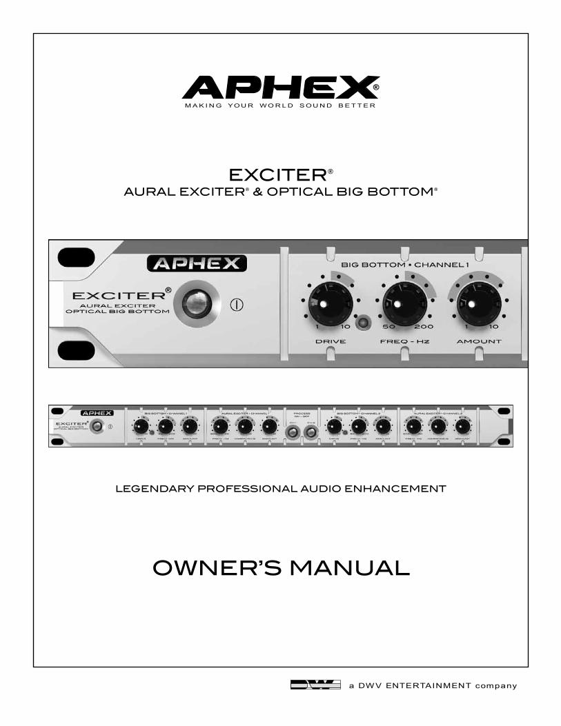
OWNER’S MANUAL
LEGENDARY PROFESSIONAL AUDIO ENHANCEMENT
EXCITER®AURAL EXCITER® & OPTICAL BIG BOTTOM®
Page 2
Exciter
CAUTION: For continued protection against risk of fire, replace only with the same type and rating of fuse.
ATTENTION: pour une protection continue contre les risques d’incendie, ne remplacer qu’avec la même valeur et même type de fusible.
WARNING: Do not place objects containing liquid on this unit as it is not designed to protect against spillage. Do not expose this unit to dripping or splashing of liquids as the unit is not designed to protect against these occur-ances.
WARNING: This unit must be connected to a mains socket outlet with a protective earthing connection.
WARNING: The Exciter has been tested and meets the FCC, CE and European Union rules, regulations, and guid-lines for use. Do not attempt to modify or change the Exciter, as this could void the regulatory compliance, which would place you at risk of losing your authority to operate the Exciter.
WARNING: Do not place objects on top of this unit if they weigh more than 10 pounds.
This equipment has been tested and found to comply with the limits for a Class B digital device, pursuant to part 15 of the FCC rules. These limits are designed to provide reasonable protection against harmful interference in a residential installation. This equipment generates, uses and can radiate radio frequency energy and, if not installed and used in accordance with the instructions, may cause harmful interference to radio communications. However, there is no guarantee that interference will not occur in a particular installation. If this equipment does cause harmful interference to radio or television reception, which can be determined by turning the equipment off and on, the user is encouraged to try to correct the interference by one or more of the following measures. 1. Reorient or relocate the receiving antenna.2. Increase the separation between the equipment and receiver.3. Connect the equipment into an outlet on a circuit different from that to which the receiver is connected.4. Consult the dealer or an experienced radio/TV technician for help.
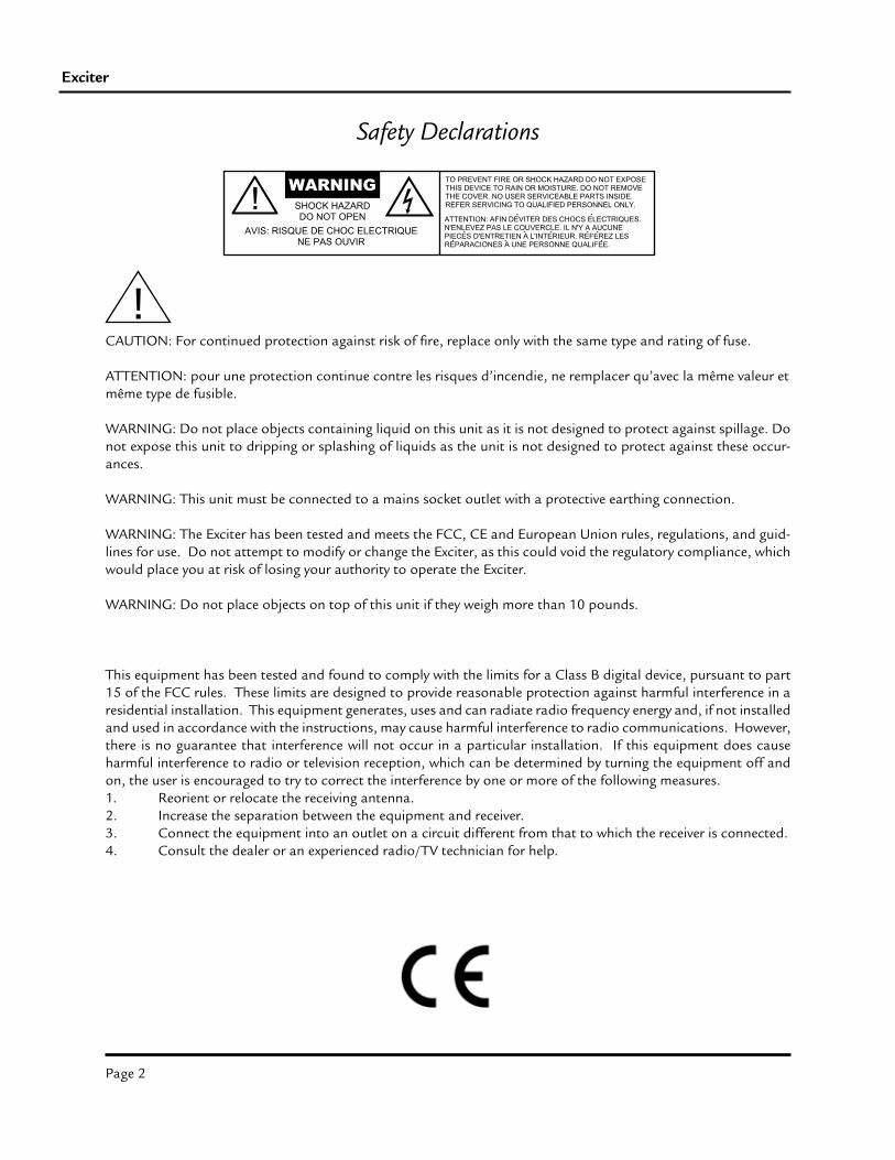
Safety Declarations
Page 3
Owner’s Manual
ATTENTION
This instruction manual is intended to be a complete reference on the Exciter, and we encourage you to read it thoroughly. At the very least, please look over the Table of Contents to familiarize yourself with the scope of infor-mation available to you.
In order to help you get maximum use and satisfaction from your new Exciter, we have tried our best to anticipate most of the questions and problems users are likely to encounter. You may find its various sections on wiring and connecting especially helpful.
Page 4
Exciter
1.0 QUICK START 1.1 Unpacking and Inspecting 5 1.2 Simple Setup 5 1.3 Suggested Control Settings 6
2.0 INTRODUCTION 2.1 The Aural Exciter and Big Bottom Technologies Explained 8 2.2 Simplified Block Diagram 9
3.0 INSTALLATION AND INTERFACING 3.1 Installation 10 3.2 Rear Panel View 10 3.3 AC Line Connector 10 3.4 Input Connectors 10 3.5 Output Connections 10 3.6 Operating Level Selector Switch 10 3.7 Grounding Lug 10 3.8 Wiring Diagrams 11
4.0 CONTROLS AND INDICATORS 4.1 Front Panel View 12 4.2 Big Bottom Frequency Control 12 4.3 Big Bottom Drive Control & Indicator 12 4.4 Big Bottom Amount Control 12 4.5 Aural Exciter Frequency Control 13 4.6 Aural Exciter Harmonics Control 13 4.7 Aural Exciter Amount Control 13 4.8 Process On/Off Buttons 13
5.0 OPERATION AND APPLICATIONS 5.1 In-Line Patches 14 5.2 Console Insert Patches 14 5.3 Effects Loop Patches 15 5.4 Optimizing Aural Exciter Effects 16 5.5 Optimizing Big Bottom Effects 17 5.6 Recording: Tracking and Mixing 17 5.7 Live Concerts and Sound Reinforcement 18 5.8 Stage Monitors 18 5.9 Guitar, Bass and Keyboard Rigs 19 5.10 Nightclubs and Discos 19 5.11 Karaoke and Stereo Systems 20 5.12 Tape Duplicating 20 5.12 Frequency Chart 216.0 WARRANTY AND SERVICE 6.1 Limited Warranty 22 6.2 Service Information 227.0 SPECIFICATIONS 7.0 Specifications 23
Table of Contents
Page 5
Owner’s Manual
1.1 UNPACKING AND INSPECTING
Your Aphex product was carefully inspected and packaged at the factory prior to shipment. The carton and its internal packing materials are designed to protect the unit from most rough handling than can occur during transport and handling. However, you should thoroughly inspect the carton and its contents for signs of physical damage before attempting to use this device. It is your responsibility to immediately report any damage to your dealer or the freight company so that a damage claim can be appropriately filed. Shipping claims are always the responsibility of the consignee (that’s you).
We also encourage you to save all of the original packing materials in the event that this unit should ever have to be returned to the dealer or factory for repair.
1.2 SIMPLE SETUP
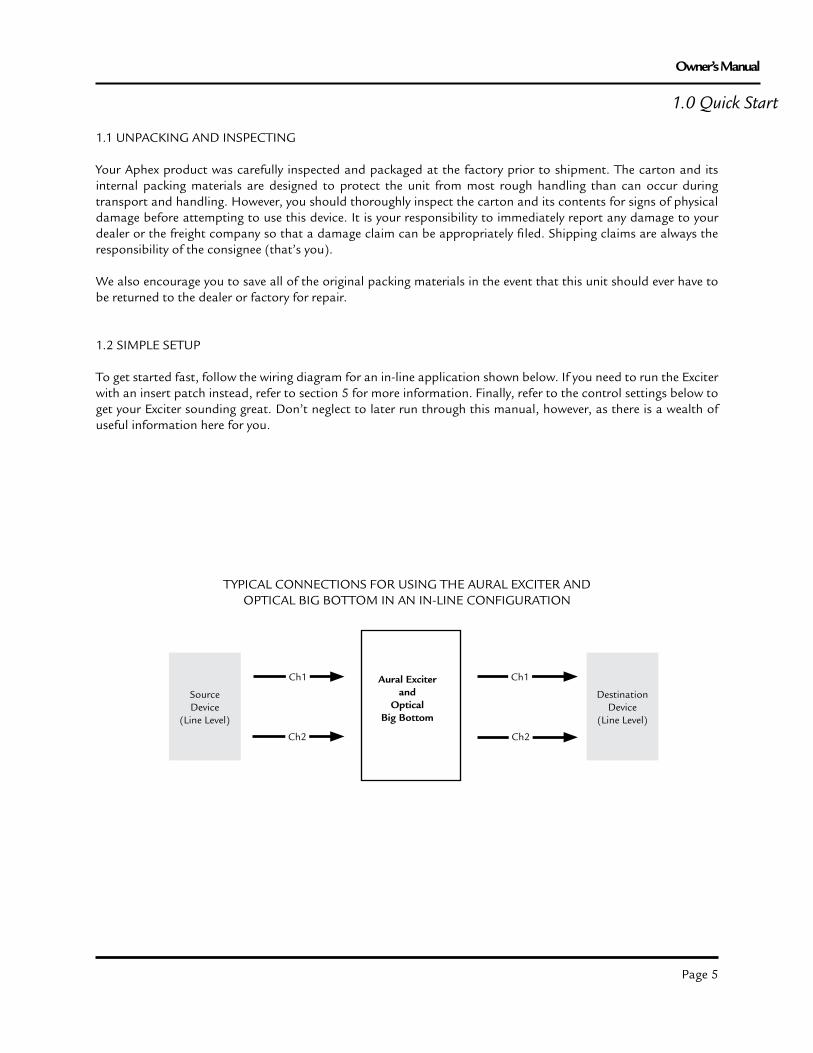
To get started fast, follow the wiring diagram for an in-line application shown below. If you need to run the Exciter with an insert patch instead, refer to section 5 for more information. Finally, refer to the control settings below to get your Exciter sounding great. Don’t neglect to later run through this manual, however, as there is a wealth of useful information here for you.
1.0 Quick Start
SourceDevice
(Line Level)A
DestinationDevice
(Line Level)
Ch1
Ch2
Ch1
Ch2
TYPICAL CONNECTIONS FOR USING THE AURAL EXCITER ANDOPTICAL BIG BOTTOM IN AN IN-LINE CONFIGURATION
Aural Exciterand
Optical Big Bottom
Page 6
Exciter
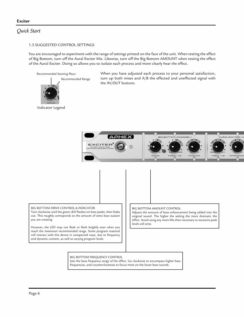
Recommended Starting Place
Recommended Range
Indicator Legend
BIG BOTTOM DRIVE CONTROL & INDICATORTurn clockwise until the green LED flashes on bass peaks, then fades out. This roughly corresponds to the amount of extra bass sustain you are creating.
However, the LED may not flash or flash brightly even when you reach the maximum recommended range. Some program material will interact with this device in unexpected ways, due to frequency and dynamic content, as well as varying program levels.
BIG BOTTOM FREQUENCY CONTROLSets the bass frequency range of the effect. Go clockwise to encompass higher bass frequencies, and counterclockwise to focus more on the lower bass sounds.
BIG BOTTOM AMOUNT CONTROLAdjusts the amount of bass enhancement being added into the original sound. The higher the setting the more dramatic the effect. Avoid using any more Mix than necessary or excessive peak levels will arise.
You are encouraged to experiment with the range of settings printed on the face of the unit. When testing the effect of Big Bottom, turn off the Aural Exciter Mix. Likewise, turn off the Big Bottom AMOUNT when testing the effect of the Aural Exciter. Doing so allows you to isolate each process and more clearly hear the effect.
Quick Start
1.3 SUGGESTED CONTROL SETTINGS
When you have adjusted each process to your personal satisfaction, turn up both mixes and A/B the effected and uneffected signal with the IN/OUT buttons.
Page 7
Owner’s Manual
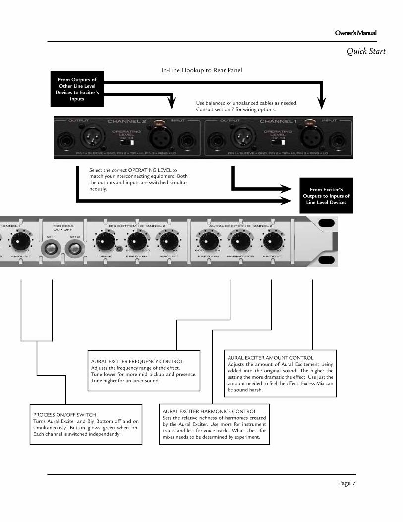
From Exciter’S Outputs to Inputs of
Line Level Devices
Quick Start
From Outputs of Other Line Level
Devices to Exciter’s Inputs
In-Line Hookup to Rear Panel
Select the correct OPERATING LEVEL to match your interconnecting equipment. Both the outputs and inputs are switched simulta-neously.
Use balanced or unbalanced cables as needed. Consult section 7 for wiring options.
AURAL EXCITER HARMONICS CONTROLSets the relative richness of harmonics created by the Aural Exciter. Use more for instrument tracks and less for voice tracks. What’s best for mixes needs to be determined by experiment.
PROCESS ON/OFF SWITCHTurns Aural Exciter and Big Bottom off and on simultaneously. Button glows green when on. Each channel is switched independently.
AURAL EXCITER FREQUENCY CONTROLAdjusts the frequency range of the effect. Tune lower for more mid pickup and presence. Tune higher for an airier sound.
AURAL EXCITER AMOUNT CONTROLAdjusts the amount of Aural Excitement being added into the original sound. The higher the setting the more dramatic the effect. Use just the amount needed to feel the effect. Excess Mix can be sound harsh.
Page 8
Exciter
2.1 THE AURAL EXCITER AND BIG BOTTOM TECHNOLOGIES EXPLAINED
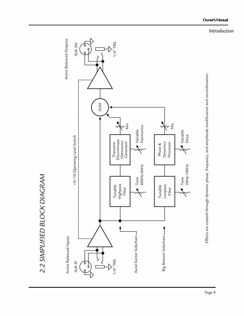
The AURAL EXCITER is an audio processor that recreates and restores missing harmonics. Harmonics are musi-cally and dynamically related to the original sound, revealing the fine differences between voices and various instru-ments. Reproduced sound is audibly different than the original live sound because of the loss in harmonic detail, often sounding dull and lifeless. The Aural Exciter adds harmonics, restoring natural brightness, clarity, and pres-ence, effectively improving detail and intelligibility. Using the Aural Exciter on specific instruments or in the final mix brings life back to the recording.
The original Aural Exciter patent disclosed a method for generating sonic harmonics which was amplitude depen-dent. In nature, generally speaking, the higher the amplitude, the higher the amount of harmonics. However, there are instances where there are high level sinusoidal waveforms, most of which should not have harmonics added, and other instances where there are waveforms which have low level transients, which could be enhanced by addi-tional harmonics. Our latest patent, the Transient Discriminate Harmonics Generator, can recognize transients (transient discriminate) over a wide dynamic range and generate harmonics on them. The result is a more predict-able and natural sounding enhancement over a wider range of inputs.
The Aural Exciter extends the high frequencies, unlike EQ’s and other brightness enhancers which only boost the high frequencies and often alter the overall tonal balance. The stereo image is enhanced with the Aural Exciter, resulting in a greater perceived loudness without an introduction of noise into the audio path. It should be pointed out that the Aural Exciter is a “single-ended” process that can be inserted at any point within the audio chain. “Single-ended” means that the unit will receive the incoming audio signal, process the program material through Aphex’s patented Aural Exciter/Big Bottom technology, then output the effected signal with no further processing required to achieve the desired aural qualities.
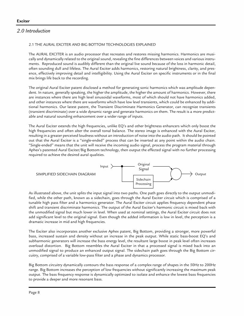
As illustrated above, the unit splits the input signal into two paths. One path goes directly to the output unmodi-fied, while the other path, known as a sidechain, goes through the Aural Exciter circuit which is comprised of a tunable high pass filter and a harmonics generator. The Aural Exciter circuit applies frequency dependent phase shift and transient discriminate harmonics. The output of the Aural Exciter’s harmonic circuit is mixed back with the unmodified signal but much lower in level. When used at nominal settings, the Aural Exciter circuit does not add significant level to the original signal. Even though the added information is low in level, the perception is a dramatic increase in mid and high frequencies.
The Exciter also incorporates another exclusive Aphex patent, Big Bottom, providing a stronger, more powerful bass, increased sustain and density without an increase in the peak output. While static bass-boost EQ’s and subharmonic generators will increase the bass energy level, the resultant large boost in peak level often increases overload distortion. Big Bottom resembles the Aural Exciter in that a processed signal is mixed back into an unmodified signal to produce an enhanced output signal. The sidechain path goes through the Big Bottom cir-cuitry, comprised of a variable low-pass filter and a phase and dynamics processor.
Big Bottom circuitry dynamically contours the bass response of a complex range of shapes in the 50Hz to 200Hz range. Big Bottom increases the perception of low frequencies without significantly increasing the maximum peak output. The bass frequency response is dynamically optimized to isolate and enhance the lowest bass frequencies to provide a deeper and more resonant bass.
2.0 Introduction
Input
SidechainProcessing
OriginalSignal
OutputSIMPLIFIED SIDECHAIN DIAGRAM
Page 9
Owner’s Manual
2.2
SIM
PLIF
IED
BLO
CK
DIA
GR
AM
Act
ive
Bal
ance
d In
puts
XLR
-3F
1/4”
TR
S
+4/-
10 O
pera
ting
Leve
l Sw
itch
Tuna
ble
Hig
hpas
sFi
lter
Tran
sien
tD
iscr
imin
ate
Har
mon
ics
Gen
erat
or
Tuna
ble
Low
pass
Filt
er
Phas
e &
Dyn
amic
sPr
oces
sorVa
riabl
eH
arm
onic
sTu
ne80
0Hz-
6kH
z
Mix
Mix
SUM
Act
ive
Bal
ance
d O
utpu
ts
XLR
-3M
1/4”
TR
S
Varia
ble
Driv
eTu
ne50
Hz-
190H
z
Aur
al E
xcit
er S
idec
hain
Big
Bot
tom
Sid
echa
in
Effe
cts
are
crea
ted
thro
ugh
dyna
mic
pha
se, f
requ
ency
, and
am
plitu
de m
odifi
catio
n an
d re
com
bina
tion.
Introduction
Page 10
Exciter
3.0 Installation & Interfacing
3.3 AC LINE CONNECTORUse only a power cord that carries approvals for use in your location. The Exciter’s internal power supply is designed to operate on nominal power sources from 100 to 240 volts a.c. at 50/60Hz without requiring the user to change any settings. In the event of failure, do not attempt to change the internal fuse because it will never blow unless the power supply fails catasrophically. When this occurs, the power supply will need to be serviced by a competent service technician.
3.4 INPUT CONNECTORS
The input connectors are located on the rear panel. There are two input connectors per channel, one 1/4” TRS phone type and one XLR-3F type. All inputs are fully balanced at all operating levels. Either of the input jacks can be used unbalanced whenever necessary (consult the wiring diagrams, next page). You can take advantage of the true balanced inputs by using a “pseudo-balanced” wiring scheme from any unbalanced outboard gear. NOTE: The TRS and XLR input jacks are wired directly together, and will severely load each other down if equip-ment is plugged into both inputs. Use only one or the other.
3.5 OUTPUT CONNECTORS
The output connectors are located on the rear panel. There are two output connectors per channel, one 1/4” TRS phone type and one XLR-3M type.
3.6 OPERATING LEVEL SWITCH
Between the input and output jacks are located the Operating Level switches. These switches set the nominal oper-ating level for all of the input and output jacks simultaneously to either -10dBV or +4dBu. You should select the position that most closely matches your signal level.
3.7 GROUNDING LUG
Sometimes it just comes down to brute force grounding. Providing such heavy, low resistance, ground current paths that little current is left to flow through your audio grounds. You can use 12 gauge, copper wire from chassis to chassis. The grounding lug is provided for just such an occasion. Equipment in rack shelves can have their chas-sis grounded to the metal rack frame and the frame itself can act as a brute force ground.
3.1 INSTALLATION
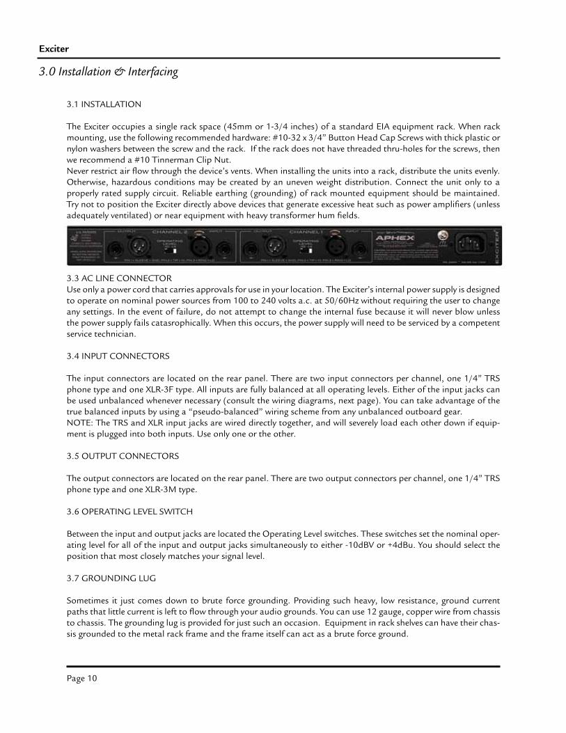
The Exciter occupies a single rack space (45mm or 1-3/4 inches) of a standard EIA equipment rack. When rack mounting, use the following recommended hardware: #10-32 x 3/4” Button Head Cap Screws with thick plastic or nylon washers between the screw and the rack. If the rack does not have threaded thru-holes for the screws, then we recommend a #10 Tinnerman Clip Nut.Never restrict air flow through the device’s vents. When installing the units into a rack, distribute the units evenly. Otherwise, hazardous conditions may be created by an uneven weight distribution. Connect the unit only to a properly rated supply circuit. Reliable earthing (grounding) of rack mounted equipment should be maintained. Try not to position the Exciter directly above devices that generate excessive heat such as power amplifiers (unless adequately ventilated) or near equipment with heavy transformer hum fields.
Page 11
Owner’s Manual
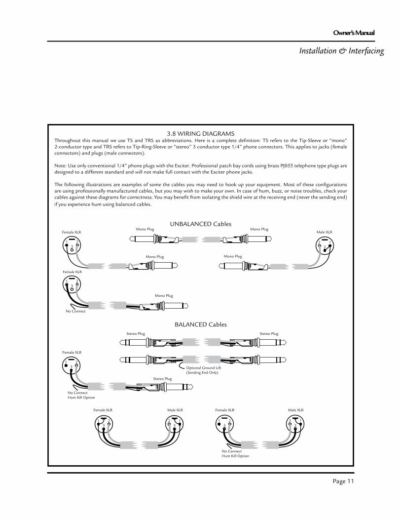
3.8 WIRING DIAGRAMSThroughout this manual we use TS and TRS as abbreviations. Here is a complete definition: TS refers to the Tip-Sleeve or “mono” 2-conductor type and TRS refers to Tip-Ring-Sleeve or “stereo” 3 conductor type 1/4” phone connectors. This applies to jacks (female connectors) and plugs (male connectors).
Note: Use only conventional 1/4” phone plugs with the Exciter. Professional patch bay cords using brass PJ055 telephone type plugs are designed to a different standard and will not make full contact with the Exciter phone jacks.
The following illustrations are examples of some the cables you may need to hook up your equipment. Most of these configurations are using professionally manufactured cables, but you may wish to make your own. In case of hum, buzz, or noise troubles, check your cables against these diagrams for correctness. You may benefit from isolating the shield wire at the receiving end (never the sending end) if you experience hum using balanced cables.
Mono Plug
Male XLR
Installation & Interfacing
UNBALANCED Cables
Stereo Plug Stereo Plug
BALANCED Cables
Optional Ground Lift(Sending End Only)
Mono Plug
Female XLRMono Plug Mono Plug
Female XLR
Mono Plug
No Connect
Female XLR
Stereo Plug
No ConnectHum Kill Option
Female XLR Female XLRMale XLR Male XLR
No ConnectHum Kill Option

Page 12
Exciter
4.0 Controls & Indicators
4.1 FRONT PANEL VIEW
4.2 BIG BOTTOM FREQUENCY CONTROL
This control lets you optimize the bass enhancement frequency band. The Exciter’s controls have typical range settings printed on the front panel. Where this is set depends upon your sound system and the type of music being played. Typically, 12:00 is a universal position. However, you may want to experiment with other settings. The range is from 50Hz to 200Hz. At center, you are tuned to about 80Hz.
4.3 BIG BOTTOM DRIVE CONTROL & INDICATOR
This control allows you to adjust the input signal to optimum levels required for Big Bottom to work effectively. To find the optimum level, turn the control clockwise until the green LED at the right of the Drive control pulses on the bass peaks. Longer and brighter pulsation means a longer bass sustain is being created. You will find a range of settings that yields very musical and powerful bass.
Please note there are valid reasons for why the green LED may not pulse by the time this control reaches 2 o’clock. The Exciter’s Operating Level switch may be set to +4dBu though you have a -10dBV input signal. On the other hand, if the green LED is pulsing strongly at settings as
low as 9 or 10 o’clock, you probably have the Operating Level switched to -10dBV though you have a +4dBu input signal. This can cause overload distortion.
Additionally, the LED may not pulse when the incoming audio has low program levels.
4.4 BIG BOTTOM AMOUNT CONTROL
This control adjusts the amount of Big Bottom enhancement being added to the original signal. The lower the setting, the subtler the effect until there is no effect at all. The higher the setting, the more dramatic the effect.
One of the benefits of the Big Bottom is that it can increase the bass power without greatly increasing the peak output level. That means that loudspeakers and amplifiers will not be overdriven even though the bass has been extended and increased in power. Extreme settings of the Big Bottom Mix control, however, will increase the peak output level significantly, so we recommend staying within some reasonable limits.
Generally, the best results are found between the 9 and 2 o’clock settings. Try working the Big Bass Tune, Drive, and Mix controls when maximizing the bass enhancement.
Page 13
Owner’s Manual
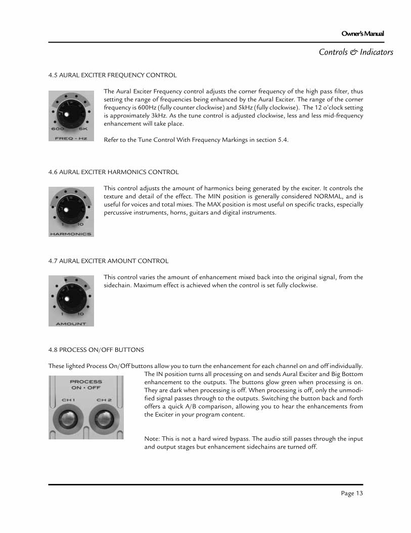
4.5 AURAL EXCITER FREQUENCY CONTROL
The Aural Exciter Frequency control adjusts the corner frequency of the high pass filter, thus setting the range of frequencies being enhanced by the Aural Exciter. The range of the corner frequency is 600Hz (fully counter clockwise) and 5kHz (fully clockwise). The 12 o’clock setting is approximately 3kHz. As the tune control is adjusted clockwise, less and less mid-frequency enhancement will take place.
Refer to the Tune Control With Frequency Markings in section 5.4.
4.6 AURAL EXCITER HARMONICS CONTROL
This control adjusts the amount of harmonics being generated by the exciter. It controls the texture and detail of the effect. The MIN position is generally considered NORMAL, and is useful for voices and total mixes. The MAX position is most useful on specific tracks, especially percussive instruments, horns, guitars and digital instruments.
4.7 AURAL EXCITER AMOUNT CONTROL
This control varies the amount of enhancement mixed back into the original signal, from the sidechain. Maximum effect is achieved when the control is set fully clockwise.
4.8 PROCESS ON/OFF BUTTONS
These lighted Process On/Off buttons allow you to turn the enhancement for each channel on and off individually. The IN position turns all processing on and sends Aural Exciter and Big Bottom enhancement to the outputs. The buttons glow green when processing is on. They are dark when processing is off. When processing is off, only the unmodi-fied signal passes through to the outputs. Switching the button back and forth offers a quick A/B comparison, allowing you to hear the enhancements from the Exciter in your program content.
Note: This is not a hard wired bypass. The audio still passes through the input and output stages but enhancement sidechains are turned off.
Controls & Indicators
Page 14
Exciter
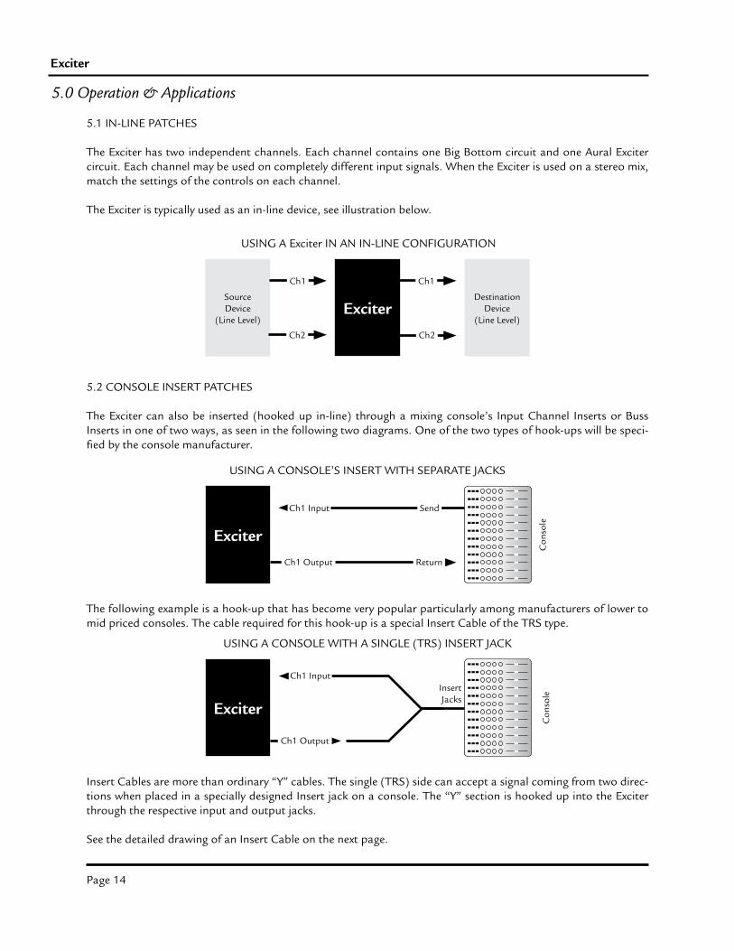
5.1 IN-LINE PATCHES
The Exciter has two independent channels. Each channel contains one Big Bottom circuit and one Aural Exciter circuit. Each channel may be used on completely different input signals. When the Exciter is used on a stereo mix, match the settings of the controls on each channel.
The Exciter is typically used as an in-line device, see illustration below.
5.2 CONSOLE INSERT PATCHES
The Exciter can also be inserted (hooked up in-line) through a mixing console’s Input Channel Inserts or Buss Inserts in one of two ways, as seen in the following two diagrams. One of the two types of hook-ups will be speci-fied by the console manufacturer.
The following example is a hook-up that has become very popular particularly among manufacturers of lower to mid priced consoles. The cable required for this hook-up is a special Insert Cable of the TRS type.
Insert Cables are more than ordinary “Y” cables. The single (TRS) side can accept a signal coming from two direc-tions when placed in a specially designed Insert jack on a console. The “Y” section is hooked up into the Exciter through the respective input and output jacks.
See the detailed drawing of an Insert Cable on the next page.
5.0 Operation & Applications
SourceDevice
(Line Level)Exciter
DestinationDevice
(Line Level)
Ch1
Ch2
Ch1
Ch2
USING A Exciter IN AN IN-LINE CONFIGURATION
USING A CONSOLE WITH A SINGLE (TRS) INSERT JACK
Exciter
Ch1 Input
Ch1 Output
USING A CONSOLE’S INSERT WITH SEPARATE JACKS
Send
Return
Exciter
Ch1 Output
Ch1 InputInsertJacks
Con
sole
Con
sole

Page 15
Owner’s Manual
WIRING A TRS INSERT CABLE
Note: Some manufacturers reverse the Tip and Sleeve connections, where the Tip is Return and the Sleeve is Send. This would mean that IN becomes OUT and OUT becomes IN when referring to the previous drawing. Be sure to check the owner’s manual of your console.
5.3 EFFECTS LOOP PATCHES
As we stated early on, the Exciter was primarily designed as an in-line device. However, if you choose to use it with a post fader aux send, keep in mind that the Exciter has two independant processers labeled channel one and chan-nel two. A cable would be patched from the aux send output to the channel one input and another cable would be patched from the channel one output to a mono effect return or input channel on the mixer. Another aux send could be used with channel two of the Exciter the same way. Also, the signal being returned back into the console is not a 100% wet effect signal. The return is a mix of effects and the original sound. Because of this we recommend that you set the mix controls of both the Aural Exciter and the Big Bottom to the maximum setting (fully clockwise) when using the Exciter in this way. Because very little Aural Excitement goes a long way, it is possible to get very good results from this type of set-up.
Exciter
USING A Exciter IN AN EFFECTS LOOP
Post Fader AUX Send
AUX Return
Con
sole
Ring(Return)
Tip(Send)
Tip
Sleeve(Ground)
Sleeve
Ring
Tip
Tip
Sleeve
Sleeve
Con
sole
Inse
rt Ja
ck
Excit
er
IN
OUT
Operation & Applications
Page 16
Exciter
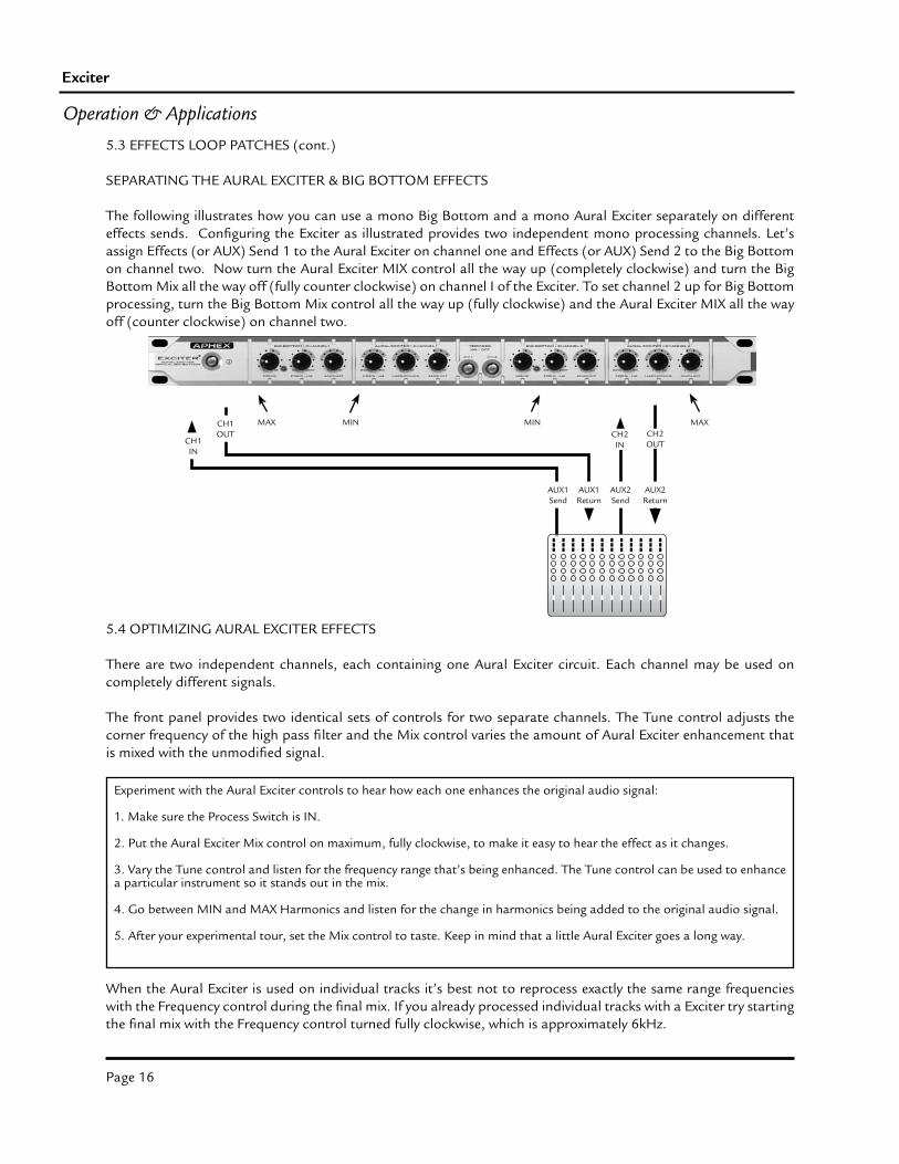
5.3 EFFECTS LOOP PATCHES (cont.)
SEPARATING THE AURAL EXCITER & BIG BOTTOM EFFECTS
The following illustrates how you can use a mono Big Bottom and a mono Aural Exciter separately on different effects sends. Configuring the Exciter as illustrated provides two independent mono processing channels. Let’s assign Effects (or AUX) Send 1 to the Aural Exciter on channel one and Effects (or AUX) Send 2 to the Big Bottom on channel two. Now turn the Aural Exciter MIX control all the way up (completely clockwise) and turn the Big Bottom Mix all the way off (fully counter clockwise) on channel I of the Exciter. To set channel 2 up for Big Bottom processing, turn the Big Bottom Mix control all the way up (fully clockwise) and the Aural Exciter MIX all the way off (counter clockwise) on channel two.
5.4 OPTIMIZING AURAL EXCITER EFFECTS
There are two independent channels, each containing one Aural Exciter circuit. Each channel may be used on completely different signals.
The front panel provides two identical sets of controls for two separate channels. The Tune control adjusts the corner frequency of the high pass filter and the Mix control varies the amount of Aural Exciter enhancement that is mixed with the unmodified signal.
When the Aural Exciter is used on individual tracks it’s best not to reprocess exactly the same range frequencies with the Frequency control during the final mix. If you already processed individual tracks with a Exciter try starting the final mix with the Frequency control turned fully clockwise, which is approximately 6kHz.
Operation & Applications
Experiment with the Aural Exciter controls to hear how each one enhances the original audio signal:
1. Make sure the Process Switch is IN.
2. Put the Aural Exciter Mix control on maximum, fully clockwise, to make it easy to hear the effect as it changes.
3. Vary the Tune control and listen for the frequency range that’s being enhanced. The Tune control can be used to enhance a particular instrument so it stands out in the mix.
4. Go between MIN and MAX Harmonics and listen for the change in harmonics being added to the original audio signal.
5. After your experimental tour, set the Mix control to taste. Keep in mind that a little Aural Exciter goes a long way.
MAX MINCH2OUT
CH2IN
MIN MAX
AUX1Send
AUX1Return
AUX2Send
AUX2Return
CH1IN
CH1OUT
Page 17
Owner’s Manual
5.5 OPTIMIZING BIG BOTTOM EFFECTS
There are two independent channels, each containing one Big Bottom circuit. Each channel may be use on com-pletely different signals. Two identical sets of controls are provided.
The Drive control needs to be set at a point where the processor receives the optimum level required for Big Bottom to work effectively. The Amount control adjusts the amount of Big Bottom enhancement being added to the unmodified signal. The Frequency control sets the frequency below which the bass enhancement effects are generated.
Next to the Drive control is a green LED indicator. When the Operating Level (+4/-10) switch on the rear panel is set correctly and the program material has enough content to drive the Big Bottom circuit, this LED should illu-minate on bass peaks.
5.6 RECORDING: TRACKING AND MIXING
The Aural Exciter restores presence and clarity, improving transient response of individual tracks or whole mixes. Increased harmonic detail enables specific instruments to stand out in the mix, offering a more “live” or spacious sound. Imaging is improved with an open “airy” quality.
Any instrument, such as a guitar, processed through the Aural Exciter circuit will have greater penetration, crisp-ness and clarity. Specific instruments pop out in the mix, giving the instrument its own sonic identity without rais-ing the volume of the instrument in the mix.Using Big Bottom on bass instruments tightens the sound, allowing individual notes to be more articulated and recognizable. Big Bottom provides more feeling, resembling a “live” sound.
In the recording studio, post production suite or similar environment, post processing of previously recorded sound tracks can restore lost vibrancy and realism, even to the extent of saving dialog or sound effects which were thought to be unusable. Instruments and vocals can be made to stand out in the mix without substantially increas-ing the mix levels or using equalization.
The Aural Exciter is especially useful in creating the perception of high frequencies and greater dynamics with pre-processing, bringing more presence and clarity to the final product.
The Exciter should be hooked up between a compressor like the Aphex 208 Easyrider Automatic Compressor and any equalization. Use the Aural Exciter in place of equalization whenever possible, as shown below.
Operation & Applications
BIG BOTTOM EXPERIMENTING
1. Make sure the Process Switch is IN.
2. Set the Tune and Mix controls to 12:00.
3. Vary the Drive control and listen to how the bass can be made to hang over, or sustain, longer. Start by adjusting the Drive control until the green LED just flashes on bass peaks, then advance the Drive incrementally.
4. Vary the Mix control and listen for how subtle or dramatic you can make the effect.
Page 18
Exciter
5.7 LIVE CONCERTS & SOUND REINFORCEMENT
The Aural Exciter adds intelligibility without increasing levels, even with speaker systems that have reduced band-width. It does this through higher harmonics generation which improves vocal articulation through a sound system. Audio that is processed by the Aural Exciter will more easily penetrate noisy and reverberant environments by adding brightness and clarity through the addition of harmonics rather than increasing gain of frequency funda-mentals which may lead to feedback. Any voice or instrument individually processed with the Aural Exciter circuit will have greater crispness and clarity allowing them to pop out in the mix with its own sonic identity.
Big Bottom inexpensively increases the bass capacity of any sound system. It is as though you’ve added subwoofers to the system. If you already have subwoofers you’ll think the number of subs in the system was increased.
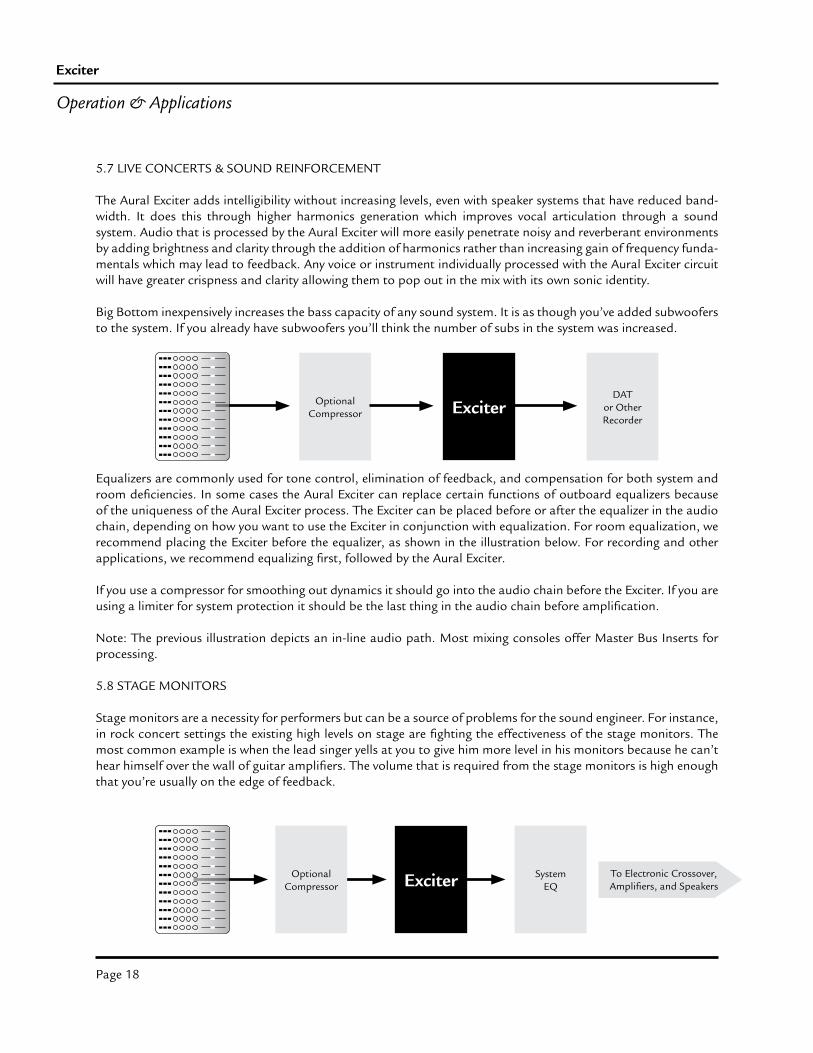
Equalizers are commonly used for tone control, elimination of feedback, and compensation for both system and room deficiencies. In some cases the Aural Exciter can replace certain functions of outboard equalizers because of the uniqueness of the Aural Exciter process. The Exciter can be placed before or after the equalizer in the audio chain, depending on how you want to use the Exciter in conjunction with equalization. For room equalization, we recommend placing the Exciter before the equalizer, as shown in the illustration below. For recording and other applications, we recommend equalizing first, followed by the Aural Exciter.
If you use a compressor for smoothing out dynamics it should go into the audio chain before the Exciter. If you are using a limiter for system protection it should be the last thing in the audio chain before amplification.
Note: The previous illustration depicts an in-line audio path. Most mixing consoles offer Master Bus Inserts for processing.
5.8 STAGE MONITORS
Stage monitors are a necessity for performers but can be a source of problems for the sound engineer. For instance, in rock concert settings the existing high levels on stage are fighting the effectiveness of the stage monitors. The most common example is when the lead singer yells at you to give him more level in his monitors because he can’t hear himself over the wall of guitar amplifiers. The volume that is required from the stage monitors is high enough that you’re usually on the edge of feedback.
Operation & Applications
OptionalCompressor Exciter
DATor OtherRecorder
SystemEQ
To Electronic Crossover,Amplifiers, and Speakers
OptionalCompressor Exciter
Page 19
Owner’s Manual
Another situation is acoustic music performances such as folk or bluegrass. In this instance there is no problem with a high stage level. However, you have instruments that by nature have a low acoustical output that require high amounts of gain to reproduce them through PA and stage monitor systems. In this situation, you’re typically on the edge of feedback especially as the number of mics increase.
In both of these examples your are trying to get more gain out of the stage monitors than the limiting factor of feedback will allow. The Aural Exciter will give you a perceived increase in volume without putting your system into feedback. Put an Aural Exciter in line when the system is stable yet close to the point of feedback. The Aural Exciter may be the most viable option under these conditions.
There are two types of monitor systems in use. The simplest and least expensive method is a foldback monitor system. Only one console is used for mixing both the “front of house” P.A. and the stage monitors. To use a Exciter in a foldback monitor system, patch directly into the Exciter from the line level monitor output on the console. The Exciter should always come before equalization and then on to the amplifier and speakers.
The other method is known as on-stage monitor mixing. In this scenario, a separate mixing console is placed on stage to mix the stage monitors. This is prevalent in larger, more sophisticated performance settings where there is typically many monitor mixes. Since we are dealing with a separate console, in most cases you’ll have a choice of using a buss insert or patching “in-line”.
5.9 GUITAR, BASS & KEYBOARD RIGS
The sampling rates of digital devices such as synthesizers, drum machines, samplers etc. limit the instruments bandwidth and resolution. They have no high end beyond a fixed point and can sound lifeless. Use of the Aural Exciter dramatically improves their overall sound by creating additional overtones, literally doubling the band-width.
Any instrument, such as a guitar, processed through the Aural Exciter circuit gives the instrument its own sonic identity without raising the volume of the instrument in the mix. Musicians can include the Exciter into their instru-ment rigs and process the sound they want before it reaches the sound mixer.
5.10 NIGHTCLUBS AND DISCOS
The Exciter is great for smaller sound systems with a limited dynamic range and frequency response. You’ll be sur-prised how much more bottom end you’ll have without adding more speakers and amplifiers. No matter how good the sound system is, adding the Exciter will improve clarity and intelligibility without increasing levels.
Big Bottom inexpensively increases the bass capacity of any sound system. It is as though you’ve added subwoofers to the system. If you already have subwoofers you’ll think the number of subs in the system was increased.
It’s also important to remember that when EQ’s are introduced into the playback system they can cause ear fatigue and speaker damage. The overuse of EQ in nightclub and disco applications is commonplace. Use the Aural Exciter in place of an EQ in these applications and music seems louder and clearer, even at low levels, saving both your ears and speakers from harm.
Operation & Applications
Page 20
Exciter
Operation & Applications
5.11 KARAOKE & STEREO SYSTEMS
The Exciter is a perfect complement to Karaoke systems. In a small club situation, often the sound system and the microphones have a limited dynamic range and frequency response. Big Bottom will help tighten and increase bass. Aural Exciter helps overdubbed vocals become more intelligible and clearer in the mix. The Exciter can give Karaoke performers that big “recording studio” sound that audiences want to hear.
The two channels in most Karaoke and consumer grade equipment are marked left (L) and right (R), rather than one (1) and two (2). Regardless of these markings, the Exciter can be used as a stereo component. Just make sure to match the settings of the controls on each channel for best results.
You can replace outboard EQ’s in home stereo systems with the Exciter. Big Bottom increases the “punch” of the bass and the Aural Exciter “pops” vocals, guitars and keyboards out front in the mix.
5.12 TAPE DUPLICATING
Tape copies actually sound better and brighter than the original if they are first processed by the Aural Exciter. Moreover, there is no generation loss! Chances of tape saturation are minimized as there is little high end boost, which is common in other enhancers.
The Exciter may be used to “pre-process” recording to anticipate the audio degradation in the medium or during subsequent reproduction. Much of the detail added by the Exciter’s Aural Exciter will survive filtering and distor-tion of the reproduction equipment, and provide a better quality audio playback.
Bit-rate reduced (data compressed) digital audio tracks sound flat and lifeless in comparison to the original. The Exciter will bring these tracks back to life without unmasking the compression artifacts.
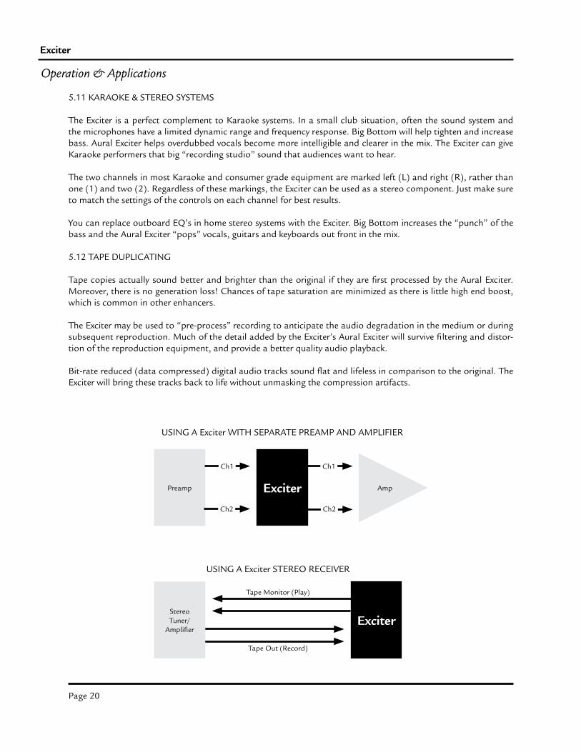
Preamp Exciter
Ch1
Ch2
Ch1
Ch2
Amp
USING A Exciter WITH SEPARATE PREAMP AND AMPLIFIER
Tape Out (Record)
Tape Monitor (Play)
StereoTuner/
AmplifierExciter
USING A Exciter STEREO RECEIVER
Page 21
Owner’s Manual
Operation & Applications
Aud
ible
Har
mon
ics
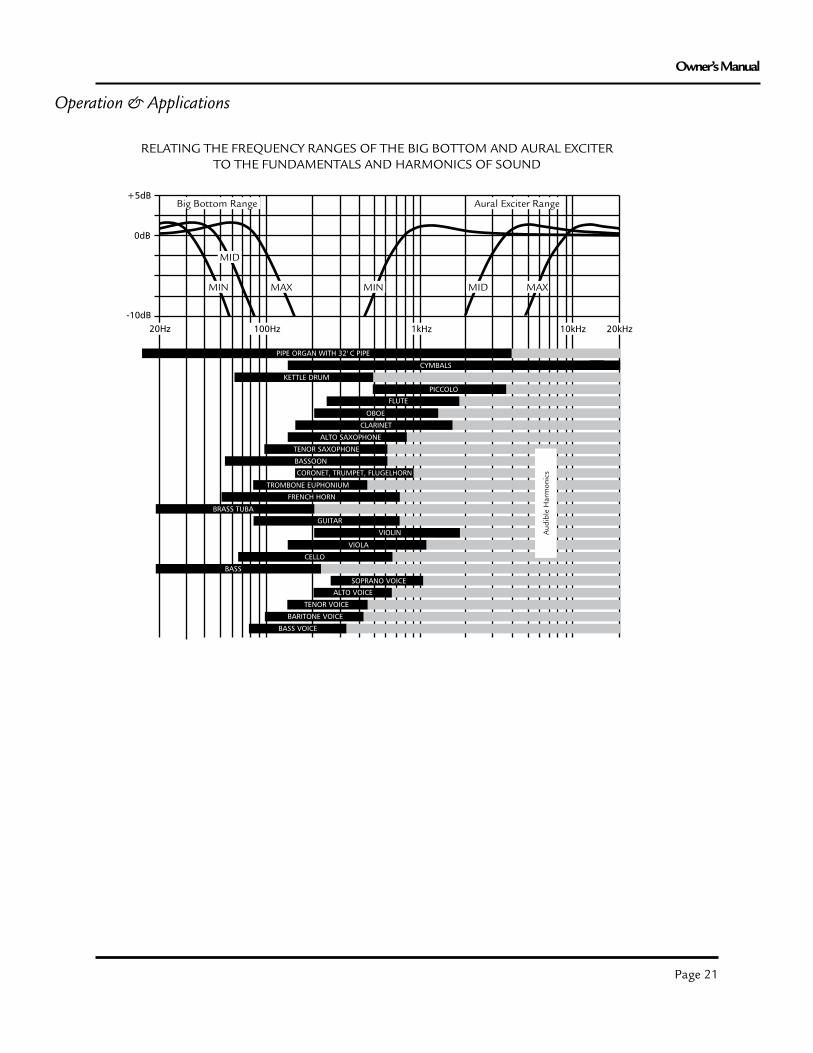
RELATING THE FREQUENCY RANGES OF THE BIG BOTTOM AND AURAL EXCITERTO THE FUNDAMENTALS AND HARMONICS OF SOUND
Big Bottom Range Aural Exciter Range
MIN
MID
MAX MIN MID MAX
Page 22
Exciter
6.2 SERVICE INFORMATION
If it becomes necessary to return this unit for repair, you must first contact Aphex for a Return Authorization (RMA number), which will need to be included with your shipment for proper identification. If available, repack this unit in its original carton and packing material. Otherwise, pack the equipment in a strong carton containing at least 2 inches of padding on all sides. Be sure the unit cannot shift around inside the carton. Include a letter explaining the symptoms and/or defect(s). Be sure to reference the RMA number in your letter and mark the RMA number on the outside of the carton. If you believe the problem should be covered under the terms of the warranty, you must also include proof of purchase. Insure your shipment and send it to:
Aphex3500 N San Fernando Blvd
Burbank, CA 91505PH: (818) 767-2929 FAX: (818) 767 -2641
6.0 Warranty & Service
6.1 Limited Warranty
PERIODOne year from date of purchase
SCOPEAll defects in workmanship and materials. The following are not covered:a. Voltage conversionsb. Units on which the serial number has been defaced, modified, or removedc. Damage or deterioration: 1. Resulting from installation and/or removal of the unit. 2. Resulting from accident, misuse, abuse, neglect, unauthorized product modification or failure to follow instructions contained in the User’s Manual. 3. Resulting from repair or attempted repair by anyone not authorized by Aphex Systems. 4. Occurring from shipping (claims must be presented to shipper).
WHO IS PROTECTEDThis warranty will be enforceable by the original purchaser and by any subsequent owner(s) during the warranty period, so long as a copy of the original Bill of Sale is submitted whenever warranty service is required.
WHAT WE WILL PAY FORWe will pay for all labor and material expenses for covered items. We will pay return shipping charges if the repairs are covered by the warranty.
LIMITATION OF WARRANTYNo warranty is made, either expressed or implied, as to the merchantability and fitness for any particular purpose. Any and all warranties are limited to the duration of the warranty stated above.
EXCLUSION OF CERTAIN DAMAGESAphex Systems’ liability for any defective unit is limited to the repair or replacement of said unit, at our option, and shall not include damages of any other kind, whether incidental, consequential, or otherwise.
Some States do not allow limitations on how long an implied warranty lasts and/or do not allow the exclusion or limitation of incidental or consequential damages, so the above limitations and exclusions may not apply to you.
This warranty gives you specific legal rights, and you may also have other rights which vary from State to State.
Page 23
Owner’s Manual
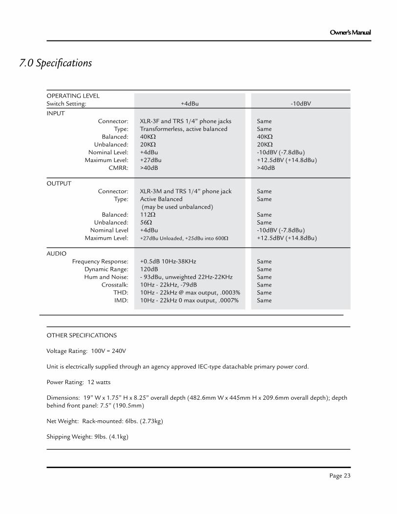
7.0 Specifications
INPUTConnector:
Type:Balanced:
Unbalanced:Nominal Level:
Maximum Level:CMRR:
OUTPUTConnector:
Type:
Balanced: Unbalanced:
Nominal LevelMaximum Level:
AUDIOFrequency Response:
Dynamic Range: Hum and Noise:
Crosstalk:THD:IMD:
OPERATING LEVELSwitch Setting: +4dBu -10dBV
XLR-3F and TRS 1/4” phone jacksTransformerless, active balanced40KΩ20KΩ+4dBu+27dBu>40dB
XLR-3M and TRS 1/4” phone jackActive Balanced (may be used unbalanced)112Ω56Ω+4dBu+27dBu Unloaded, +25dBu into 600Ω
+0.5dB 10Hz-38KHz120dB- 93dBu, unweighted 22Hz-22KHz10Hz - 22kHz, -79dB10Hz - 22kHz @ max output, .0003%10Hz - 22kHz 0 max output, .0007%
SameSame40KΩ20KΩ-10dBV (-7.8dBu)+12.5dBV (+14.8dBu)>40dB
SameSame
SameSame-10dBV (-7.8dBu)+12.5dBV (+14.8dBu)
SameSameSameSameSameSame
OTHER SPECIFICATIONS
Voltage Rating: 100V = 240V
Unit is electrically supplied through an agency approved IEC-type datachable primary power cord.
Power Rating: 12 watts
Dimensions: 19” W x 1.75” H x 8.25” overall depth (482.6mm W x 445mm H x 209.6mm overall depth); depth behind front panel: 7.5” (190.5mm)
Net Weight: Rack-mounted: 6lbs. (2.73kg)
Shipping Weight: 9lbs. (4.1kg)
Page 24
Exciter
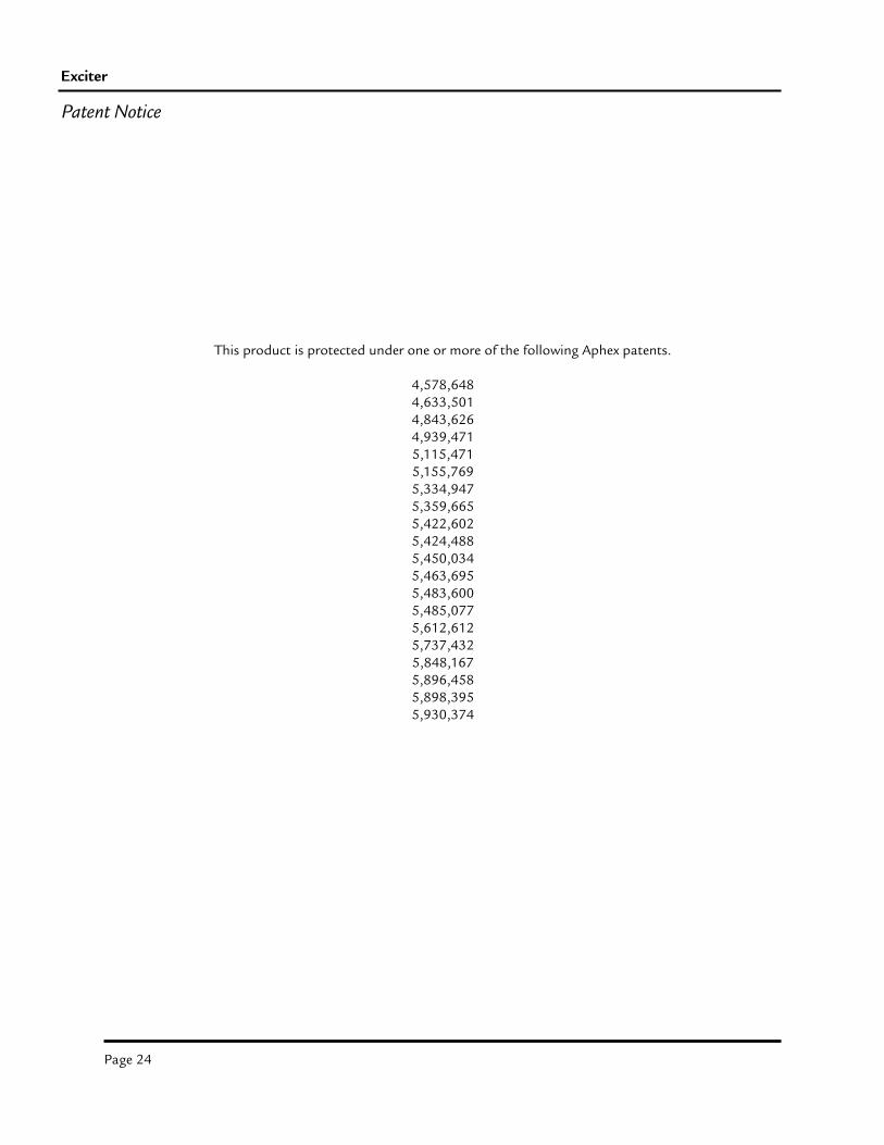
This product is protected under one or more of the following Aphex patents.
4,578,6484,633,5014,843,6264,939,4715,115,4715,155,7695,334,9475,359,6655,422,6025,424,4885,450,0345,463,6955,483,6005,485,0775,612,6125,737,4325,848,1675,896,4585,898,3955,930,374
Patent Notice