Excel 3000 Booth Installation - Nordsonemanuals.nordson.com/finishing/files/Powder/1095481a.pdf ·...
36
Excel 3000 Series Powder Coating Booth Installation Customer Product Manual Part 1095481A Issued 2/10 NORDSON CORPORATION • AMHERST, OHIO • USA For parts and technical support, call the Finishing Customer Support Center at (800) 433-9319. This document is subject to change without notice. Check http://emanuals.nordson.com for the latest version.
Transcript of Excel 3000 Booth Installation - Nordsonemanuals.nordson.com/finishing/files/Powder/1095481a.pdf ·...

Excel 3000 SeriesPowder Coating Booth Installation
Customer Product ManualPart 1095481A
Issued 2/10
NORDSON CORPORATION • AMHERST, OHIO • USA
For parts and technical support, call the Finishing Customer Support Center at (800) 433-9319.
This document is subject to change without notice.Check http://emanuals.nordson.com for the latest version.
Part 1095481A � 2010 Nordson Corporation
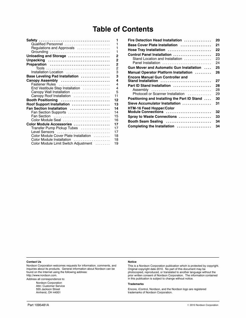
Table of ContentsSafety 1. . . . . . . . . . . . . . . . . . . . . . . . . . . . . . . . . . . . . . .
Qualified Personnel 1. . . . . . . . . . . . . . . . . . . . . . . . .Regulations and Approvals 1. . . . . . . . . . . . . . . . . .Grounding 1. . . . . . . . . . . . . . . . . . . . . . . . . . . . . . . . .
Unloading and Storage 2. . . . . . . . . . . . . . . . . . . . . . .Unpacking 2. . . . . . . . . . . . . . . . . . . . . . . . . . . . . . . . . .Preparation 2. . . . . . . . . . . . . . . . . . . . . . . . . . . . . . . . .
Tools 2. . . . . . . . . . . . . . . . . . . . . . . . . . . . . . . . . . .Installation Location 3. . . . . . . . . . . . . . . . . . . . . . . .
Base Leveling Pad Installation 3. . . . . . . . . . . . . . . .Canopy Assembly 4. . . . . . . . . . . . . . . . . . . . . . . . . . .
Fastener Rules 4. . . . . . . . . . . . . . . . . . . . . . . . . . . .End Vestibule Step Installation 4. . . . . . . . . . . . . . .Canopy Wall Installation 5. . . . . . . . . . . . . . . . . . . . .Canopy Roof Installation 11. . . . . . . . . . . . . . . . . . . .
Booth Positioning 12. . . . . . . . . . . . . . . . . . . . . . . . . . .Roof Support Installation 13. . . . . . . . . . . . . . . . . . . . .Fan Section Installation 14. . . . . . . . . . . . . . . . . . . . . .
Fan Section Supports 14. . . . . . . . . . . . . . . . . . . . . . .Fan Section 15. . . . . . . . . . . . . . . . . . . . . . . . . . . . . . .Color Module Seal 16. . . . . . . . . . . . . . . . . . . . . . . . . .
Color Module Accessories 17. . . . . . . . . . . . . . . . . . . .Transfer Pump Pickup Tubes 17. . . . . . . . . . . . . . . .Level Sensors 17. . . . . . . . . . . . . . . . . . . . . . . . . . . . .Color Module Cover Plate Installation 18. . . . . . . . .Color Module Installation 18. . . . . . . . . . . . . . . . . . . .Color Module Limit Switch Adjustment 19. . . . . . . .
Fire Detection Head Installation 20. . . . . . . . . . . . . . .Base Cover Plate Installation 21. . . . . . . . . . . . . . . . .Hose Tray Installation 22. . . . . . . . . . . . . . . . . . . . . . . .Control Panel Installation 23. . . . . . . . . . . . . . . . . . . . .
Stand Location and Installation 23. . . . . . . . . . . . . . .Panel Installation 24. . . . . . . . . . . . . . . . . . . . . . . . . . .
Gun Mover and Automatic Gun Installation 25. . . .Manual Operator Platform Installation 26. . . . . . . . .Encore Manual Gun Controller and Stand Installation 27. . . . . . . . . . . . . . . . . . . . . . . . . . . .Part ID Stand Installation 28. . . . . . . . . . . . . . . . . . . . .
Assembly 28. . . . . . . . . . . . . . . . . . . . . . . . . . . . . . . . .Photocell or Scanner Installation 29. . . . . . . . . . . . .
Positioning and Installing the Part ID Stand 30. . . .Sieve Accumulator Installation 31. . . . . . . . . . . . . . . .HTM-16 Feed Hopper/Color Module Connections 32. . . . . . . . . . . . . . . . . . . . . . . . .Spray to Waste Connections 33. . . . . . . . . . . . . . . . . .Booth Seam Sealing 34. . . . . . . . . . . . . . . . . . . . . . . . .Completing the Installation 34. . . . . . . . . . . . . . . . . . .
Contact UsNordson Corporation welcomes requests for information, comments, andinquiries about its products. General information about Nordson can befound on the Internet using the following address:http://www.nordson.com.Address all correspondence to:
Nordson CorporationAttn: Customer Service555 Jackson StreetAmherst, OH 44001
NoticeThis is a Nordson Corporation publication which is protected by copyright.Original copyright date 2010. No part of this document may bephotocopied, reproduced, or translated to another language without theprior written consent of Nordson Corporation. The information containedin this publication is subject to change without notice.
Trademarks
Encore, iControl, Nordson, and the Nordson logo are registeredtrademarks of Nordson Corporation.

Excel� 3000 Series Booth Installation 1
Part 1095481A� 2010 Nordson Corporation
Excel� 3000 Series Booth InstallationThis manual provides instructions and guidelines for the installation of atypical Excel 3000 Series powder coating booth. All systems are different;refer to your system drawings.
Once the booth is erected and all components are positioned and installed,your Nordson representatives will help you complete the system installation,start up the system, and train you how to operate it properly.
Safety
Qualified Personnel Equipment owners are responsible for making sure that Nordson equipmentis installed by qualified personnel. Qualified personnel are those employeesor contractors who are trained to safely perform their assigned tasks. Theyare familiar with all relevant safety rules and regulations and are physicallycapable of performing their assigned tasks.
Regulations and Approvals Before installing any system equipment, make sure it is rated and approvedfor the environment in which it will be used. Any approvals obtained forNordson equipment will be voided if instructions for installation, operation,and service are not followed.
All phases of equipment installation must comply with all federal, state, andlocal codes. Refer to the National Fire Protection Association publicationNFPA 33 for standards on installation and operation of powder spraysystems.
Grounding Grounding inside and around the booth openings must comply with NFPArequirements for Class II Division 1 or 2 Hazardous Locations. Refer toNFPA 33, NFPA 70 (NEC articles 500, 502, and 516), and NFPA 77, latestconditions.
Equipment to be grounded includes, but is not limited to, the floor of thespray area, booth base, operator platforms, hoppers, feed center, gunpositioners, fixed gun stands, and afterfilter. Refer to the groundinginstructions in the Nordson equipment manuals for more information.

Excel� 3000 Series Booth Installation2
Part 1095481A � 2010 Nordson Corporation
Unloading and Storage The Excel 3000 booth is shipped partially assembled, wired and plumbed.The degree of pre-assembly depends on the size of the booth. You will needforklift trucks and other rigging equipment to unload the system from thecarrier.
WARNING: Do not attempt to lift equipment using covers, doors, panels, orcable and hose connections. Always balance the load when lifting. Neverput stress on flat panel sheets.
Move all equipment to an indoor storage area, close to the installation site.
NOTE: Equipment stored outside and not protected from the elementscould be damaged, voiding any warranty.
Unpacking Locate the system electrical control panel. The control panel contains theshipping documents, listing the skids and boxes and their designations. Aseparate enclosed Packing Checklist lists the items on each skid and ineach box.
When the shipment is unloaded, inventory and inspect each skid and box.If you discover damage or an inventory discrepancy, report it to yourNordson representative immediately. Report any damages or discrepanciesto the carrier and keep a copy of the report for your Nordson representative.
Preparation
Tools Installation of the ColorMax powder coating booth and its components willbe easier and faster if the proper tools are available. Have the followingtools on hand:
� Rigging equipment, including a forklift
� C-clamps or welder’s clamps
� Chalk line
� Plumb-bob and line
� Multimeter
� Electrician’s tools
� Mechanic’s tools, including pipe wrenches
� Portable power drills and wrenches
� Razor knife
� Levels and squares
� Tubing cutter

Excel� 3000 Series Booth Installation 3
Part 1095481A� 2010 Nordson Corporation
Installation Location No special foundation is required. The floor should be smooth and level.The spray room must be large enough to provide working clearances forboth installation and operation. Refer to your system drawings for planviews and layouts.
The conveyor should already be installed, since the booth is located off theconveyor line.
Base Leveling Pad Installation 1. Roll the base to the installation area. Lift the base and remove the
shipping casters.
2. See Figure 1, Detail A. Thread one locking nut onto each leveling pad.
3. Install the leveling pads into the holes in the cross beams, then threadanother locking nut onto each leveling pad.
4. Use the bottom locking nut to adjust the leveling pad up or down to levelthe base. See Detail B. The typical base-to-floor dimension is 12inches, though this can vary depending on the floor and the customerrequirements.
Cross Beam
12.00 in.(typical)
Hole
A
B
Detail ADetail B
Locking Nut
Locking Nut
Leveling Pad
Figure 1 Leveling Pad Installation

Excel� 3000 Series Booth Installation4
Part 1095481A � 2010 Nordson Corporation
Canopy Assembly
Fastener Rules � Metal Panel to Metal Panel: Use metal fasteners.
� Metal Panel to Plastic Panel: Use metal fasteners.
� Plastic Panel to Plastic Panel: Use plastic fasteners.
End Vestibule Step Installation 1. See Figure 2. Fasten the bottom panel to the base with 5/16-18 hex
head bolts and hex nuts.
2. Fasten the step panel to the bottom panel with 5/16-18 button headbolts and hex nuts.
Button Head Bolts
Step Panel
Hex Nuts
Bottom Panel
Hex Nuts
Hex Head Bolts
Figure 2 End Vestibule Step Installation

Excel� 3000 Series Booth Installation 5
Part 1095481A� 2010 Nordson Corporation
Canopy Wall Installation 1. See Figure 3. Attach a side panel to an end panel with 5/16-18 hex
head bolts and hex nuts to create a corner assembly.
2. Move the corner assembly to the corner of the base as shown. Line upthe bottom inside corner of the assembly with the corner of the floor.
3. Mark the positions of the holes on the booth base flange on the canopypanel flanges. Drill holes in the canopy flanges with a 3/8 in. drill bit.
4. Secure the corner assembly to the base with 5/16-18 hex head boltsand hex nuts.
Side PanelEnd Panel
A
Detail A
Base Flange
FloorCorner
PanelFlanges
Figure 3 Corner Assembly

Excel� 3000 Series Booth Installation6
Part 1095481A � 2010 Nordson Corporation
Canopy Wall Installation (contd)
5. See Figure 4. Line up the collector mouth flange with the side panelflange so that the mount and panel are flush on the inside of the booth.
6. Clamp the flanges together with 5 flange brackets, spacing the bracketsevenly. Tighten the bracket bolts to clamp the flanges together.
A
Mouth Flange
Side PanelFlange
Detail A
Collector Mouth
Brackets
Side Panel
Figure 4 Securing Side Panels to Collector Mouth

Excel� 3000 Series Booth Installation 7
Part 1095481A� 2010 Nordson Corporation
7. See Figure 5. Align the mouth top panel flange holes with the holes inthe side panel and collector mouth flanges.
8. Fasten the plastic side and top panels together with plastic 5/16-18 hexhead bolts and hex nuts.
9. Fasten the top panel and the collector mouth together with 5/16-18button head bolts and hex nuts. Insert the button head bolts up throughthe collector mouth flange and top panel flange.
Collector Mouth
Top Panel
Side Panel
Button Head Bolts
Figure 5 Securing Top Panels to Collector Mouth and Side Panels

Excel� 3000 Series Booth Installation8
Part 1095481A � 2010 Nordson Corporation
Canopy Wall Installation (contd)
10. See Figure 6. Build a second corner panel assembly as shown, using5/16-18 hex head bolts and hex nuts.
11. Attach this corner panel assembly to the booth base as shown inFigure 3.
12. Attach the corner panel assembly to the top panel and collector mouthas shown in Figure 4.
Side Panel
End Panel
Collector Mouth
Top Panel
Figure 6 Corner Panel Assembly

Excel� 3000 Series Booth Installation 9
Part 1095481A� 2010 Nordson Corporation
13. See Figure 7. Build corner assemblies for the other side of the booth asshown, using 5/16-18 hex head bolts and hex nuts.
14. Position the corner assemblies on the base so that the inside corners ofthe assemblies align with the corners of the floor.
15. Fasten the side panels together with 5/16-18 hex head bolts and hexnuts.
16. Align the panel flanges with the base and mark the positions of the holesin the base on the panel bottom flanges. Drill holes in the panel flangeswith a 3/8 in. drill bit.
17. Fasten the panels to the base with 5/16-18 hex head bolts and hexnuts.
End Panel
End Panel
Drill Holes
Side Panels
Figure 7 Assembling Opposite Side of Canopy

Excel� 3000 Series Booth Installation10
Part 1095481A � 2010 Nordson Corporation
Canopy Wall Installation (contd)
18. See Figure 9, Detail A. Align the holes in the top vestibule panel withthe holes in the side panels and end panels. Fasten the top panels tothe side and end panels with 5/16-18 hex head bolts and hex nuts.
19. See Detail B. Fasten the end panels to the vestibule bottom and steppanels with 5/16-18 hex head bolts and hex nuts.
A
Detail A
Top VestibulePanels
End Panels
Side Panels
B
Detail B
End Panels
Step Panel
Figure 8 Top Vestibule Panel Installation

Excel� 3000 Series Booth Installation 11
Part 1095481A� 2010 Nordson Corporation
Canopy Roof Installation NOTE: Start the roof installation by installing one roof panel on one side.At least 2 people are required to install the roof panels.
1. See Figure 9. Attach the roof panels to the top vestibule panels, sidepanels, and other roof panels with 5/16-18 hex head bolts and hex nuts.
Roof Panels
Figure 9 Roof Installation
2. See Figure 10. Place the conveyor shrouds flush against the roof panelflange and secure them with 5/16-18 flat head bolts and hex nuts.Install the blots from the conveyor slot side, so that the heads go into thecountersunk holes in the shrouds.
ConveyorShroud
Flat Head Bolts
Counter-SunkHoles
Figure 10 Conveyor Shroud Installation
Excel� 3000 Series Booth Installation12
Part 1095481A � 2010 Nordson Corporation
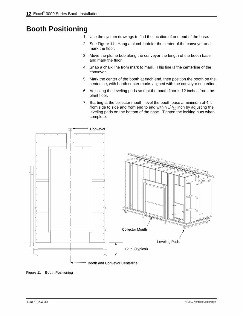
Booth Positioning 1. Use the system drawings to find the location of one end of the base.
2. See Figure 11. Hang a plumb bob for the center of the conveyor andmark the floor.
3. Move the plumb bob along the conveyor the length of the booth baseand mark the floor.
4. Snap a chalk line from mark to mark. This line is the centerline of theconveyor.
5. Mark the center of the booth at each end, then position the booth on thecenterline, with booth center marks aligned with the conveyor centerline.
6. Adjusting the leveling pads so that the booth floor is 12 inches from theplant floor.
7. Starting at the collector mouth, level the booth base a minimum of 4 ftfrom side to side and from end to end within ±1/16 inch by adjusting theleveling pads on the bottom of the base. Tighten the locking nuts whencomplete.
Conveyor
Booth and Conveyor Centerline
12 in. (Typical)
Collector Mouth
Leveling Pads
Figure 11 Booth Positioning
Excel� 3000 Series Booth Installation 13
Part 1095481A� 2010 Nordson Corporation
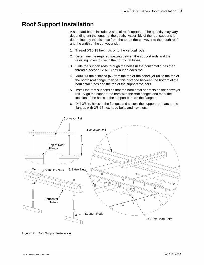
Roof Support Installation A standard booth includes 3 sets of roof supports. The quantity may varydepending ont the length of the booth. Assembly of the roof supports isdetermined by the distance from the top of the conveyor to the booth roofand the width of the conveyor slot.
1. Thread 5/16-18 hex nuts onto the vertical rods.
2. Determine the required spacing betwen the support rods and theresulting holes to use in the horizontal tubes.
3. Slide the support rods through the holes in the horizontal tubes thenthread a second 5/16-18 hex nut on each rod.
4. Measure the distance (N) from the top of the conveyor rail to the top ofthe booth roof flange, then set this distance between the bottom of thehorizontal tubes and the top of the support rod bars.
5. Install the roof supports so that the horizontal bar rests on the conveyorrail. Align the support rod bars with the roof flanges and mark thelocation of the holes in the support bars on the flanges.
6. Drill 3/8 in. holes in the flanges and secure the support rod bars to theflanges with 3/8-16 hex head bolts and hex nuts.
N
HorizontalTubes
5/16 Hex Nuts
Support Rods
Conveyor Rail
Top of RoofFlange
Conveyor Rail
3/8 Hex Nuts
3/8 Hex Head Bolts
Figure 12 Roof Support Installation

Excel� 3000 Series Booth Installation14
Part 1095481A � 2010 Nordson Corporation
Fan Section Installation
Fan Section Supports 1. See Detail A. Thread a locking nut onto each leveling pad, then install
the leveling pads into the holes in the fan section supports.
2. Thread a second locking nut onto each leveling pad. Do not tightenthese locking nuts.
3. Align the fan section supports with the collector mouth, using the bottomlocking nuts on the leveling pads to align the bolt holes in the supportflanges with the holes in the collector mouth and level the supports.
4. See Detail B. Secure the supports to the collector mount with 3/8-16hex head bolts.
5. Install the fan support brackets on the fan supports with 3/8-16 hexhead bolts.
A
Detail A
Detail B
B
Leveling Pads
Fan Section Supports
Locking Nuts
Hex Head Bolts
Detail C
Fan Support Brackets
Hex Head Bolts
C
Weld Nuts
Weld Nuts
Figure 13 Fan Section Support Installation
Excel� 3000 Series Booth Installation 15
Part 1095481A� 2010 Nordson Corporation
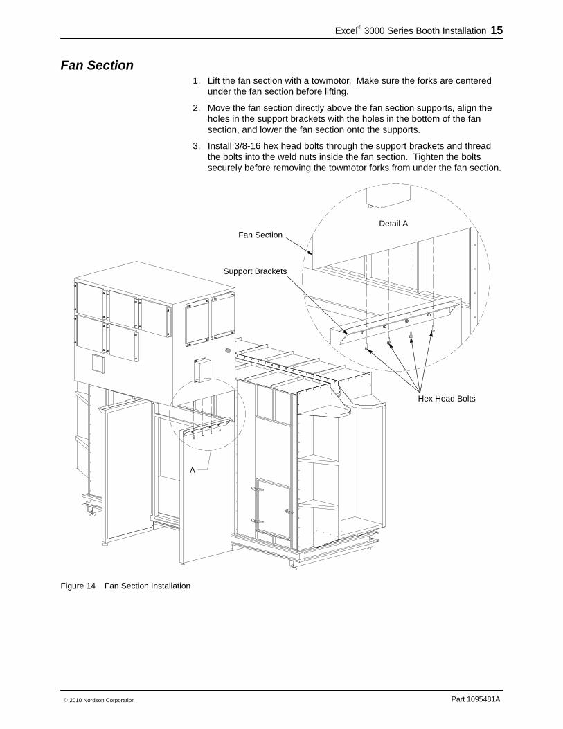
Fan Section 1. Lift the fan section with a towmotor. Make sure the forks are centered
under the fan section before lifting.
2. Move the fan section directly above the fan section supports, align theholes in the support brackets with the holes in the bottom of the fansection, and lower the fan section onto the supports.
3. Install 3/8-16 hex head bolts through the support brackets and threadthe bolts into the weld nuts inside the fan section. Tighten the boltssecurely before removing the towmotor forks from under the fan section.
A
Detail A
Hex Head Bolts
Fan Section
Support Brackets
Figure 14 Fan Section Installation

Excel� 3000 Series Booth Installation16
Part 1095481A � 2010 Nordson Corporation
Color Module Seal 1. Locate the valve stem track section, which has a 3/8 in. hole in the
center of the section.
2. Align the valve stem hole and screw holes in the track section with theholes in the bottom of the fan section.
3. Fasten the track section to the fan section with #10 flat head screws, flatwashers, lock washers, and nuts.
4. Fasten the rest of the track sections to the fan section, working aroundthe fan opening.
5. Locate the valve stem on the color module seal. Insert the valve steminto the hole in the valve stem track section, then install the seal into thetrack.
Valve StemTrack Section
Valve StemFlat Head Screws
Flat WashersLock WashersNuts
Track Sections
Seal
Figure 15 Color Module Seal Installation

Excel� 3000 Series Booth Installation 17
Part 1095481A� 2010 Nordson Corporation
Color Module Accessories NOTE: Accessories shown in this section are optional. Your system maybe different.
Cover plates should be installed last so that the inside of the color modulecan be accessed to install other accessories.
Transfer Pump Pickup Tubes 1. See Figure 16, Detail A. Slide the tube holder gasket onto the tube
holder, then install the tube holder into the tube well. Secure the tubeholder to the well by reaching inside the module and threading thelocking nut onto the holder. Tighten the nut securely.
2. Slide the pickup tube into the tube holder.
3. Plug the unused pickup tube wells with the plugs shipped with thesystem.
Level Sensors 1. See Figure 16, Detail B. Slide the level sensor gasket onto the sensor
well, then install the sensor well into the sensor hole.
2. Secure the sensor well by reaching inside the module and threading thewell nut onto the sensor well. Tighten the nut securely.
3. Plug any unused sensor well holes with the plugs shipped with thesystem.
Detail A
Detail BA
B
Pickup Tube
Tube Holder
Gasket
Locking Nut
Tube Well
Sensor Well
Gasket
Well Nut
Figure 16 Color Module Transfer Pump Pickup Tube and Level Sensor Well Installation

Excel� 3000 Series Booth Installation18
Part 1095481A � 2010 Nordson Corporation
Color Module Cover Plate Installation If needed, install cover plates on the color module with 5/16-18 hex headbolts. The cover plates are configured for your application. The uppercover plate can be either blank or a direct vent plate. The lower plate canaccomodate up to four vent stub plates that connect feed hopper vent hosesto the color module. Blank plates cover the unused openings.
Blank Plate Over Direct Vent Opening Remote Vent Cover Plates
Vent Plate
BlankPlate
Vent StubPlate
Figure 17 Color Module Cover Plate Installation
Color Module Installation Roll the color module under the fan section. Hook the clamps onto theclamp brackets on both sides of the color module, then crank the strapratchets to tighten the color module snugly against the collector mouth.
A
Clamp Bracket
Clamp
StrapRatchet
Fan SupportColor Module
Figure 18 Color Module Installation

Excel� 3000 Series Booth Installation 19
Part 1095481A� 2010 Nordson Corporation
Color Module Limit Switch Adjustment The color module limit switch is a safety feature that prevents the exhaustfan from running unless a color module is installed under the fan section. Ifthe limit switch is not closed when the color module is clamped to the booth,the following adjustments can be made:
� Rotate the limit switch arm by loosening the allen screw shown inView 1.
� Extend the limit switch arm by loosening the allen screw shown inView 2.
A
Detail A
View 1
View 2
Allen Screw
Allen Screw
Figure 19 Color Module Limit Switch Adjustment

Excel� 3000 Series Booth Installation20
Part 1095481A � 2010 Nordson Corporation
Fire Detection Head Installation 1. Align the holes in the top bracket with the holes in the back of the
detector head. Secure the bracket to the head with 1/4-20 hex headbolts, washers, and nuts.
2. Align the end holes in the bottom bracket with the end holes in the topbracket.
3. Fasten the brackets together with 3/8-16 hex head bolts, washers, andnuts.
4. Determine the desired location for the detector head, so it can seediagonally across the booth. Most effective location is on the vestiblefloor, or on the outside edge of the floor.
5. Drill a hole in the desired detector head mounting location with a 3/8 in.bit. Fasten the detector head to the booth with a 3/8-16 hex head bolt,washers, and nut. Point the detector head toward the opposite top endof the the booth.
1
2
3
Fan Support
Flat Washers1/4 Bolts
Flat Washers
Lock Washers
Nuts
3/8 Bolts
Flat Washers
Flat Washers
Lock Washers
Nuts
3/8 Bolt
AlternateLocation
Nut
Lock Washer
Flat Washer
Figure 20 Fire Detection Head Installation

Excel� 3000 Series Booth Installation 21
Part 1095481A� 2010 Nordson Corporation
Base Cover Plate Installation 1. Locate the base side and end covers. The side covers are longer than
the end covers.
2. Starting on one end of the booth, align the holes in the covers with thepre-drilled holes in the base.
3. Use 5/16-18 hex head self-tapping screws to fasten the covers to thebase. Work around the booth until the base is completely covered.
5/16 Self-Tapping Screws
CoversSide Covers
End Covers
Figure 21 Base Cover Plate Installation
Excel� 3000 Series Booth Installation22
Part 1095481A � 2010 Nordson Corporation
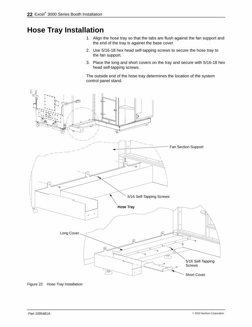
Hose Tray Installation 1. Align the hose tray so that the tabs are flush against the fan support and
the end of the tray is againet the base cover.
2. Use 5/16-18 hex head self-tapping screws to secure the hose tray tothe fan support.
3. Place the long and short covers on the tray and secure with 5/16-18 hexhead self-tapping screws.
The outside end of the hose tray determines the location of the systemcontrol panel stand.
Hose Tray
Fan Section Support
Hose Tray
5/16 Self-Tapping Screws
Long Cover
Short Cover
5/16 Self-TappingScrews
Figure 22 Hose Tray Installation
Excel� 3000 Series Booth Installation 23
Part 1095481A� 2010 Nordson Corporation
Control Panel Installation
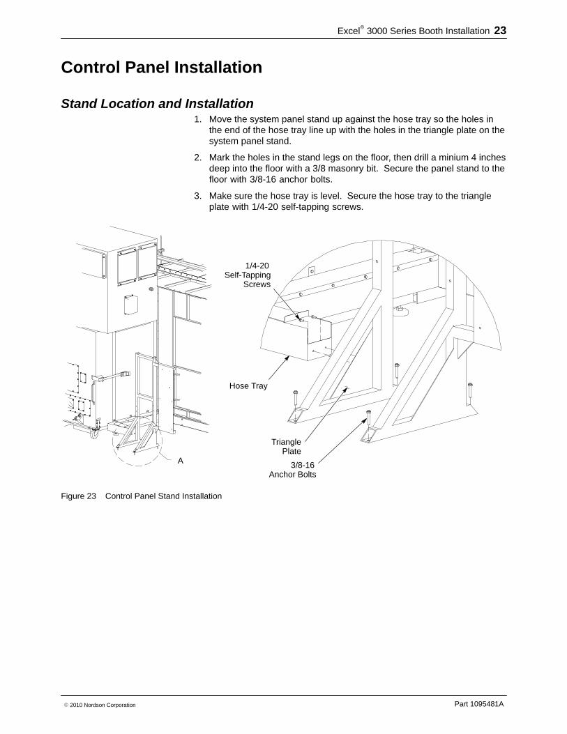
Stand Location and Installation 1. Move the system panel stand up against the hose tray so the holes in
the end of the hose tray line up with the holes in the triangle plate on thesystem panel stand.
2. Mark the holes in the stand legs on the floor, then drill a minium 4 inchesdeep into the floor with a 3/8 masonry bit. Secure the panel stand to thefloor with 3/8-16 anchor bolts.
3. Make sure the hose tray is level. Secure the hose tray to the triangleplate with 1/4-20 self-tapping screws.
A
1/4-20Self-Tapping
Screws
TrianglePlate
3/8-16Anchor Bolts
Hose Tray
Figure 23 Control Panel Stand Installation

Excel� 3000 Series Booth Installation24
Part 1095481A � 2010 Nordson Corporation
Panel Installation Install the control panels as shown in Figure 24 with 5/16-18 hex head boltsand hex nuts.
System Electrical Panel
System Pneumatic Panel
Fire Detection Panel
VFD Panel(Exhaust Fan)
Figure 24 Control Installation
Excel� 3000 Series Booth Installation 25
Part 1095481A� 2010 Nordson Corporation
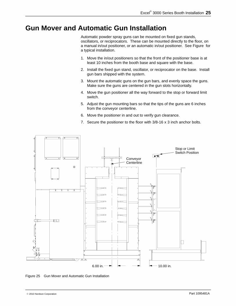
Gun Mover and Automatic Gun Installation Automatic powder spray guns can be mounted on fixed gun stands,oscillators, or reciprocators. These can be mounted directly to the floor, ona manual in/out positioner, or an automatic in/out positioner. See Figure fora typical installation.
1. Move the in/out positioners so that the front of the positioner base is atleast 10 inches from the booth base and square with the base.
2. Install the fixed gun stand, oscillator, or reciprocator on the base. Installgun bars shipped with the system.
3. Mount the automatic guns on the gun bars, and evenly space the guns.Make sure the guns are centered in the gun slots horizontally.
4. Move the gun positioner all the way forward to the stop or forward limitswitch.
5. Adjust the gun mounting bars so that the tips of the guns are 6 inchesfrom the conveyor centerline.
6. Move the positioner in and out to verify gun clearance.
7. Secure the positioner to the floor with 3/8-16 x 3 inch anchor bolts.
6.00 in. 10.00 in.
ConveyorCenterline
Stop or LimitSwitch Position
Figure 25 Gun Mover and Automatic Gun Installation

Excel� 3000 Series Booth Installation26
Part 1095481A � 2010 Nordson Corporation
Manual Operator Platform Installation Place the manual operator platforms in front of the operator openings in thecanopy. Use the platform leveling pads to adjust the platform height andlevel the platforms. The platforms should be level with the top of the boothfloor.
Leveling Pads
OperatorPlatform
OperatorOpening
BoothFloor
Figure 26 Operator Platform Installation

Excel� 3000 Series Booth Installation 27
Part 1095481A� 2010 Nordson Corporation
Encore Manual Gun Controller and Stand Installation 1. Locate the manual gun controller stand next to the operator platform so
that the operator can easily access it. Secure the stand to the floor with5/16-18 x 3 inch anchor bolts.
2. Secure the power unit bracket to the stand with 1/4-20 x .75 inchself-tapping screws.
3. Secure the power unit to the bracket with 1/4-20 x .75 inch pan headscrews.
4. Attach the Encore interface panel to the top bracket 1/4-20 x .75 panhead screws.
1/4-20 x 0.75Pan Head
Screws
Interface Panel
Power Unit
Power UnitBracket1/4-20 x 0.75
Self-TappingScrews
1/4-20 x .0.75Pan HeadScrews
5/16-18Anchor Bolts
Top Bracket
Figure 27 Manual Gun Controller and Stand Installation

Excel� 3000 Series Booth Installation28
Part 1095481A � 2010 Nordson Corporation
Part ID Stand Installation
Assembly Assemble the part ID stand by installing the crossbars on the left and rightbracket assemblies with the nuts and bolts taped to the stand. Mountingchannels are installed at the factory.
NOTE: Assemble stand in front of booth, so that top crossbar can beinstalled over the conveyor.
AA
Bolts
Crossbar
Mounting Channels
Nuts
Crossbar
Crossbar
Conveyor
Figure 28 Part ID Stand Assembly
Excel� 3000 Series Booth Installation 29
Part 1095481A� 2010 Nordson Corporation
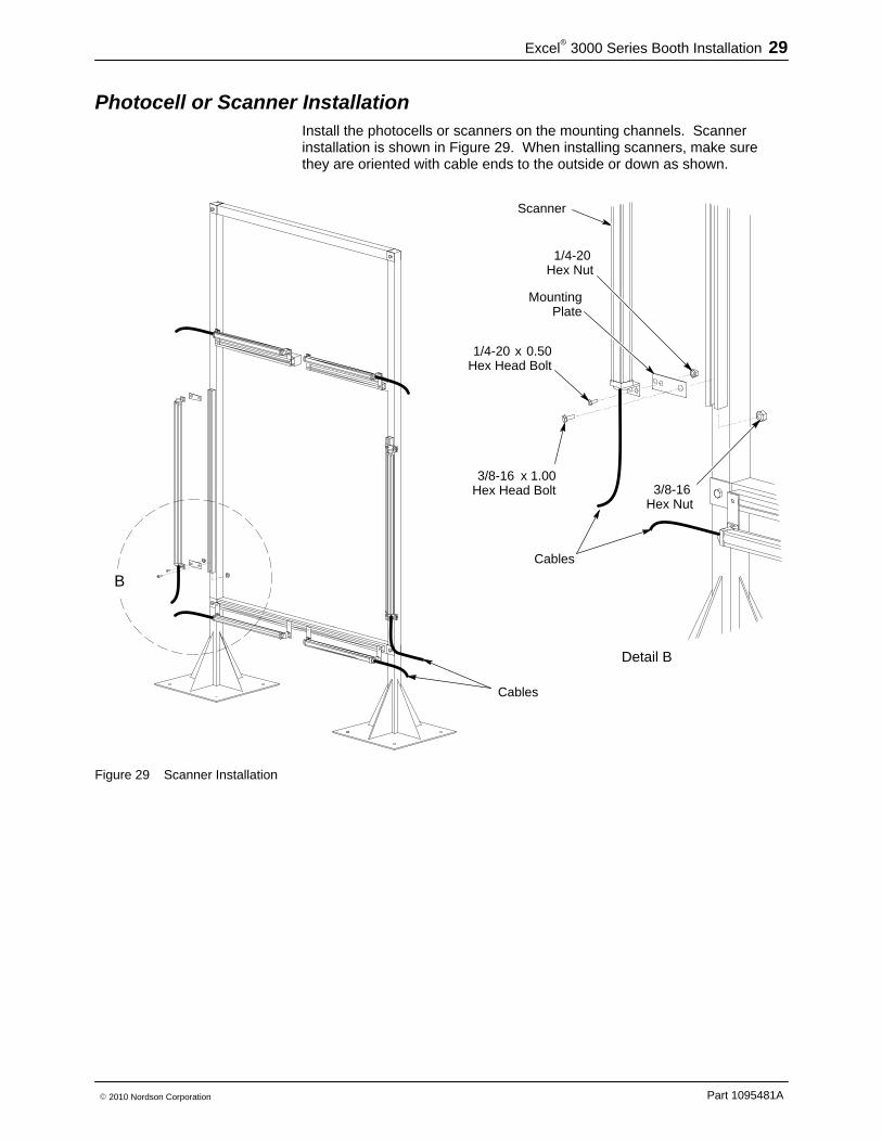
Photocell or Scanner Installation Install the photocells or scanners on the mounting channels. Scannerinstallation is shown in Figure 29. When installing scanners, make surethey are oriented with cable ends to the outside or down as shown.
B
Detail B
3/8-16 x 1.00Hex Head Bolt
Scanner
1/4-20 x 0.50Hex Head Bolt
1/4-20Hex Nut
3/8-16Hex Nut
MountingPlate
Cables
Cables
Figure 29 Scanner Installation

Excel� 3000 Series Booth Installation30
Part 1095481A � 2010 Nordson Corporation
Positioning and Installing the Part ID Stand 1. Refer to your system plan view drawings for the distance away from the
booth entrance to locate the stand.
2. Align the center of the stand with the center of the conveyor and thecenter of the booth so that part hangers will clear the upper scannerbrackets.
3. Secure the stand to the floor with 3/8-16 x 3 inch anchor bolts.
Detail A
A
3/8-16Anchor Bolts
Figure 30 Positioning and Installing Part ID Stand

Excel� 3000 Series Booth Installation 31
Part 1095481A� 2010 Nordson Corporation
Sieve Accumulator Installation Install the sieve accumulator on the sieve. For AZO sieves, use 5/16-18 x1.50 hex head bolts and hex nuts.
Bolts
AZO Sieve
Accumulator
Powder Inlets
Vent Tube
Vent Assist Air Connection
Figure 31 Installing the Sieve Accumulator

Excel� 3000 Series Booth Installation32
Part 1095481A � 2010 Nordson Corporation
HTM-16 Feed Hopper/Color Module Connections See Figure 32. This hopper is used when reclaiming powder.
1. Install the color module cover plates and vent stubs included with thesystem with 5/16-18 hex head bolts.
2. If supplied with your system, install the angled hopper vent on theHTM-16 feed hopper.
3. Move the hopper in front of the color module and connect the hoppervent to the vent cover with 5/16-18 hex head bolts.
4. Connect one end of the 3 in. vent hose to the vent stub plate and theother end to the accumulator vent tube. Secure the vent hose with theincluded hose clamps.
5. Install the transfer pumps and connect transfer hose from the pumps tothe sieve accumulator powder inlets.
6. Connect air tubing for vent assist, hopper fluidizing, and sieve aircontrols. Air is normally supplied from the system pneumatic panel.
Transfer Hoses
Vent Stub Plate
Vent Cover Plate
Vent Hose
Vent Assist
SieveAir
Con-trols
Vent Tube
Hopper Vent
Cover Plate
Transfer Pumps
Figure 32 HTM-16 Feed Hopper Connections to Color Module

Excel� 3000 Series Booth Installation 33
Part 1095481A� 2010 Nordson Corporation
Spray to Waste Connections Figure 33 shows the typical connections for a spray to waste system.
1
2
3
4
5
6
5
1
2
7
8
9
10
11
12
4
118
Figure 33 Spray to Waste Connections
1. Vent hoses2. Hose clamps3. Waste container4. Ground cable and clamp
5. Transfer hoses6. Feed pumps7. Atomizing air (to gun controller)8. Flow-rate air (to gun controller)
9. Feed hose (to spray gun)10. Feed hopper11. Fluidizing air12. Transfer pumps

Excel� 3000 Series Booth Installation34
Part 1095481A � 2010 Nordson Corporation
Booth Seam Sealing NOTE: This procedure should only be done under the direction of aNordson representative.
1. Clean and vacuum the inside corners and seams of the canopy panelsand stainless steel floor. Leave the plastic film on the stainless steel toprotect it while sealing the seams.
2. Apply blue masking tape to both sides of all vertical, horizontal, and floorseams, maintaining a 1/8 inch gap on either side of the seam.
3. Apply two-component Pro-Set sealer to all seams, making sure none ofthe sealer gets on the canopy panels or stainless steel surfaces.
4. Remove excess sealer from the seams before it sets up.
5. Remove the blue masking tape from the seams after the sealer sets up.
6. Let the sealer stand for 24 hours before preparing the booth forproduction.
Completing the Installation 1. Position the iControl console as shown in your system plan view
drawings. The typical location is to one side of the booth entrance.
2. Install pneumatic and electrical drops as shown on your systemdrawings. Make the remaining pneumatic connections shown on thesystem drawings, using the tubing provided.
3. Install the remaining electrical panels, control panels, and junction boxesas shown on the drawings.
NOTE: Make the electrical connections shown on the system drawings,using the cables provided. Plug and Spray Wiring Diagrams and electricalpanels are included in the Excel 3000 Powder Coating System manual(p/n 1095480A). All field wiring must be done by a qualified electricianaccording to code.
Your Nordson installer and field engineers will help you complete the rest ofthe system installation and startup the system.


![(5) C n & Excel Excel 7 v) Excel Excel 7 )Þ77 Excel Excel ... · (5) C n & Excel Excel 7 v) Excel Excel 7 )Þ77 Excel Excel Excel 3 97 l) 70 1900 r-kž 1937 (filllß)_] 136.8cm 136.8cm](https://static.fdocuments.us/doc/165x107/5f71a890b98d435cfa116d55/5-c-n-excel-excel-7-v-excel-excel-7-77-excel-excel-5-c-n-.jpg)