EXAMPLES SEE ALSO HISTORY - LinuxCNC · Aofthe GS2 manual). It disables deceleration over-voltage...
364
LinuxCNC(1) The Enhanced Machine Controller LinuxCNC(1) NAME linuxcnc - LinuxCNC (The Enhanced Machine Controller) SYNOPSIS linuxcnc [-v][-d][INIFILE] DESCRIPTION linuxcnc is used to start LinuxCNC (The Enhanced Machine Controller). It starts the realtime system and then initializes a number of LinuxCNC components (IO, Motion, GUI, HAL, etc). The most important parameter is INIFILE, which specifies the configuration name you would like to run. If INIFILE is not specified, the linuxcnc script presents a graphical wizard to let you choose one. OPTIONS -v Be a little bit verbose. This causes the script to print information as it works. -d Print lots of debug information. All executed commands are echoed to the screen. This mode is useful when something is not working as it should. INIFILE The ini file is the main piece of an LinuxCNC configuration. It is not the entire configuration; there are various other files that go with it (NML files, HAL files, TBL files, VAR files). It is, how- ever, the most important one, because it is the file that holds the configuration together. It can adjust a lot of parameters itself, but it also tells linuxcnc which other files to load and use. There are several ways to specify which config to use: Specify the absolute path to an ini, e.g. linuxcnc /usr/local/linuxcnc/configs/sim/sim.ini Specify a relative path from the current directory, e.g. linuxcnc configs/sim/sim.ini Otherwise, in the case where the INIFILE is not specified, the behavior will depend on whether you configured linuxcnc with --enable-run-in-place. If so, the linuxcnc config chooser will search only the configs directory in your source tree. If not (or if you are using a packaged version of linuxcnc), it may search several directories. The config chooser is currently set to search the path: ˜/linuxcnc/configs:/home/buildslave/emc2-buildbot/wheezy-amd64-clang/docs/build/configs EXAMPLES linuxcnc linuxcnc configs/sim/sim.ini linuxcnc /etc/linuxcnc/sample-configs/stepper/stepper_mm.ini SEE ALSO halcmd(1) Much more information about LinuxCNC and HAL is available in the LinuxCNC and HAL User Manuals, found at /usr/share/doc/linuxcnc/. HISTORY LinuxCNC Documentation 2006-02-20 1
Transcript of EXAMPLES SEE ALSO HISTORY - LinuxCNC · Aofthe GS2 manual). It disables deceleration over-voltage...

LinuxCNC(1) TheEnhanced Machine Controller LinuxCNC(1)
NAMElinuxcnc − LinuxCNC (The Enhanced Machine Controller)
SYNOPSISlinuxcnc [-v] [ -d] [ INIFILE]
DESCRIPTIONlinuxcnc is used to start LinuxCNC (The Enhanced Machine Controller). It starts the realtime system andthen initializes a number of LinuxCNC components (IO, Motion, GUI, HAL, etc). The most importantparameter isINIFILE, which specifies the configuration name you would like to run. If INIFILE is notspecified, thelinuxcnc script presents a graphical wizard to let you choose one.
OPTIONS−v Be a little bit verbose. This causes the script to print information as it works.
−d Print lots of debug information. All executed commands are echoed to the screen. This mode isuseful when something is not working as it should.
INIFILEThe ini file is the main piece of an LinuxCNC configuration. It is not the entire configuration;there are various other files that go with it (NML files, HAL files, TBL files, VAR files). It is, how-ev er, the most important one, because it is the file that holds the configuration together. It canadjust a lot of parameters itself, but it also tellslinuxcnc which other files to load and use.
There are several ways to specify which config to use:
Specify the absolute path to an ini, e.g.linuxcnc /usr/local/linuxcnc/configs/sim/sim.ini
Specify a relative path from the current directory, e.g.linuxcnc configs/sim/sim.ini
Otherwise, in the case where theINIFILE is not specified, the behavior will depend on whetheryou configured linuxcnc with--enable-run-in-place. If so, the linuxcnc config chooser willsearch only the configs directory in your source tree.If not (or if you are using a packaged versionof linuxcnc), it may search several directories. The config chooser is currently set to search thepath:
˜/linuxcnc/configs:/home/buildslave/emc2-buildbot/wheezy-amd64-clang/docs/build/configs
EXAMPLESlinuxcnc
linuxcnc configs/sim/sim.ini
linuxcnc /etc/linuxcnc/sample-configs/stepper/stepper_mm.ini
SEE ALSOhalcmd(1)
Much more information about LinuxCNC and HAL is available in the LinuxCNC and HAL User Manuals,found at /usr/share/doc/linuxcnc/.
HISTORY
LinuxCNC Documentation 2006-02-20 1

LinuxCNC(1) TheEnhanced Machine Controller LinuxCNC(1)
BUGSNone known at this time.
AUTHORThis man page written by Alex Joni, as part of the LinuxCNC Enhanced Machine Controller project.
REPORTING BUGSReport bugs to alex_joni AT users DOT sourceforge DOT net
COPYRIGHTCopyright © 2006 Alex Joni.This is free software; see the source for copying conditions.There is NO warranty; not even for MER-CHANTABILITY or FITNESS FOR A PARTICULAR PURPOSE.
2 2006-02-20 LinuxCNCDocumentation

axis-remote(1) TheEnhanced Machine Controller axis-remote(1)
NAMEaxis−remote − AXIS Remote Interface
SYNOPSISaxis−remoteOPTIONS|FILENAME
DESCRIPTIONaxis−remote is a small script that triggers commands in a running AXIS GUI.Useaxis−remote −−helpfor further information.
OPTIONS−−ping, −p
Check whether AXIS is running.
−−reload, −rMake AXIS reload the currently loaded file.
−−clear, −cMake AXIS clear the backplot.
−−quit, −qMake AXIS quit.
−−help, −h, −?Display a list of valid parameters foraxis−remote.
−−mdi COMMAND , −m COMMANDRun the MDI commandCOMMAND .
FILENAMELoad the G-code fileFILENAME .
SEE ALSOaxis(1)
Much more information about LinuxCNC and HAL is available in the LinuxCNC and HAL User Manuals,found at /usr/share/doc/linuxcnc/.
HISTORYBUGS
None known at this time.
AUTHORThis man page written by Alex Joni, as part of the LinuxCNC project.
REPORTING BUGSReport bugs to alex_joni AT users DOT sourceforge DOT net
COPYRIGHTCopyright © 2007 Alex Joni.This is free software; see the source for copying conditions. There is NO warranty; not even for MER-CHANTABILITY or FITNESS FOR A PARTICULAR PURPOSE.
LinuxCNC Documentation 2007-04-01 3

AXIS(1) TheEnhanced Machine Controller AXIS(1)
NAMEaxis − AXIS LinuxCNC Graphical User Interface
SYNOPSISaxis−ini INIFILE
DESCRIPTIONaxis is one of the Graphical User Interfaces (GUI) for LinuxCNC It gets run by the runscript usually.
OPTIONSINIFILE
The ini file is the main piece of an LinuxCNC configuration. It is not the entire configuration;there are various other files that go with it (NML files, HAL files, TBL files, VAR files). It is, how-ev er, the most important one, because it is the file that holds the configuration together. It canadjust a lot of parameters itself, but it also tellsLinuxCNC which other files to load and use.
SEE ALSOLinuxCNC(1)
Much more information about LinuxCNC and HAL is available in the LinuxCNC and HAL User Manuals,found at /usr/share/doc/LinuxCNC/.
HISTORYBUGS
None known at this time.
AUTHORThis man page written by Alex Joni, as part of the LinuxCNC project.
REPORTING BUGSReport bugs to alex_joni AT users DOT sourceforge DOT net
COPYRIGHTCopyright © 2007 Alex Joni.This is free software; see the source for copying conditions.There is NO warranty; not even for MER-CHANTABILITY or FITNESS FOR A PARTICULAR PURPOSE.
4 2007-04-01 LinuxCNCDocumentation

LinuxCNC(1) LinuxCNC(1)
NAMEelbpcom − Communicate with Mesa ethernet cards
SYNOPSISCommon options:
elbpcom [−−ip=IP] [−−port=PORT] [−−timeout=TIMEOUT]
Reading data:elbpcom [common options] −−space=SPACE [−−info] −−address=ADDRESS−−read=LENGTH
Writing data:elbpcom [common options] −−space=SPACE −−address=ADDRESS−−write=HEXDATA
Sending arbitrary packets:elbpcom [common options] HEXDATA
DESCRIPTIONRead or write data from a Mesa ethernet card that uses the LBP16 protocol, such as the 7i80. This can beuseful for performing certain low-level tasks.
For more information about the meaning of each address space, see the card documentation. Incorrect useof this utility can have neg ative effects such as changing the board’s IP address or even corrupting theFPGA bitfile in the eeprom.For some tasks, such as updating FPGA bitfiles and setting IP addresses,mesaflash(1) is a more appropriate tool.
If not specified, the default values are−−ip=192.168.1.121−−port=27181−−timeout=.2
This example demonstrates reading the HOSTMOT2 identifying string from the IDROM in space 0:$ elbpcom −−space 0 −−address 0x104 −−read 8> 82420401< 484f53544d4f5432
HOSTMOT2First the request is shown in hex. Thenthe response (if any) is shown in hex. Finally, the response isshown in ASCII, with "." replacing any non-ASCII characters. This is similar to the following invocationsof mesaflash:
$ ./mesaflash −−device 7i80 −−rpo 0x10454534F48$ ./mesaflash −−device 7i80 −−rpo 0x10832544F4D
but notice its different treatment of byte order.
SEE ALSOmesaflash(1), hostmot2(9), hm2_eth(9), Mesa’s documentation for the Anything I/O boards⟨http://www.mesanet.com⟩.
LinuxCNC Documentation 2015-04-18 5

GLADEVCP(1) TheEnhanced Machine Controller GLADEVCP(1)
NAMEgladevcp − Virtual Control Panel for LinuxCNC based on Glade, Gtk and HAL widgets
SYNOPSISgladevcp[−g WxH+X+Y] [−c component-name] [−u handler] [−U useroption] [−H halfile] [−d] myfile.ui
OPTIONS−g WxH+X+Y
This sets the initial geometry of the root window. Use ’WxH’ for just size, ’+X+Y’ for just posi-tion, or ’WxH+X+Y’ for both. Size / position use pixel units. Position is referenced from top left.
−c component-nameUsecomponent-nameas the HAL component name. If the component name is not specified, thebasename of the ui file is used.
−u handlerInstructs gladevcp to inspect the Python scripthandlerfor event handlers, and connect them to sig-nals in the ui file.
−U useroptiongladevcp collects alluseroptionstrings and passes them to the handler init() method as a list ofstrings without further inspection.
−x XID Reparent gladevcp into an existing windowXID instead of creating a new top level window.
−H halfilegladevcp runshalfile - a list of HAL commands - by executinghalcmd −c halfileafter the HALcomponent is finalized.
−d enable debug output.
−R gtkrcfileexplicitly load a gtkrc file.
−t THEMEset gtk theme. Default issystemtheme. Different panels can have different themes.
−m MAXIMUMforce panel window to maxumize. Together with the−g geometryoption one can move the panelto a second monitor and force it to use all of the screen
−R explicitly deactivate workaround for a gtk bug which makes matches of widget and widget_classmatches in gtk theme and gtkrc files fail. Normally not needed.
SEE ALSOGladeVCPin the LinuxCNC documentation for a description of gladevcp’s capabilities and the associatedHAL widget set, along with examples
6 2010-12-20 LinuxCNCDocumentation

gs2_vfd(1) LinuxCNC Documentation gs2_vfd(1)
NAMEgs2_vfd− HAL userspace component for Automation Direct GS2 VFD’s
SYNOPSISgs2_vfd[OPTIONS]
DESCRIPTIONThis manual page explains thegs2_vfdcomponent. This component reads and writes to the GS2 via a mod-bus connection.
gs2_vfdis for use with LinuxCNC
OPTIONS−b, −−bits <n>
(default 8) Set number of data bits to <n>, where n must be from 5 to 8 inclusive
−d, −−device <path>(default /dev/ttyS0) Set the name of the serial device node to use.
−v, −−verboseTurn on verbose mode.
−g, −−debugTurn on debug messages. Note that if there are serial errors, this may become annoying. Debugmode will cause all modbus messages to be printed in hex on the terminal.
−n, −−name <string>(default gs2_vfd) Set the name of the HAL module. The HAL comp name will be set to <string>,and all pin and parameter names will begin with <string>.
−p, −−parity [even,odd,none](default odd) Set serial parity to even, odd, or none.
−r, −−rate <n>(default 38400) Set baud rate to <n>. It is an error if the rate is not one of the following: 110, 300,600, 1200, 2400, 4800, 9600, 19200, 38400, 57600, 115200
−s, −−stopbits [1,2](default 1) Set serial stop bits to 1 or 2
−t, −−target <n>(default 1) Set MODBUS target (slave) number. This must match the device number you set on theGS2.
−A, −−accel−seconds <n>(default 10.0) Seconds to accelerate the spindle from 0 to Max RPM.
−D, −−decel−seconds <n>(default 0.0) Seconds to decelerate the spindle from Max RPM to 0. If set to 0.0 the spindle willbe allowed to coast to a stop without controlled deceleration.
−R, −−braking−resistorThis argument should be used when a braking resistor is installed on the GS2 VFD (see AppendixA of the GS2 manual). It disables deceleration over-voltage stall prevention (see GS2 modbusParameter 6.05), allowing the VFD to keep braking even in situations where the motor is regener-ating high voltage. Theregenerated voltage gets safely dumped into the braking resistor.
PINS
GS2 VFD January 1, 2009 7

gs2_vfd(1) LinuxCNC Documentation gs2_vfd(1)
<name>.DC−bus−volts (float, out)from the VFD
<name>.at−speed (bit, out)when drive is at commanded speed
<name>.err−reset (bit, in)reset errors sent to VFD
<name>.firmware−revision (s32, out)from the VFD
<name>.frequency−command (float, out)from the VFD
<name>.frequency−out (float, out)from the VFD
<name>.is−stopped (bit, out)when the VFD reports 0 Hz output
<name>.load−percentage (float, out)from the VFD
<name>.motor−RPM (float, out)from the VFD
<name>.output−current (float, out)from the VFD
<name>.output−voltage (float, out)from the VFD
<name>.power−factor (float, out)from the VFD
<name>.scale−frequency (float, out)from the VFD
<name>.speed−command (float, in)speed sent to VFD in RPM It is an error to send a speed faster than the Motor Max RPM as set inthe VFD
<name>.spindle−fwd (bit, in)1 for FWD and 0 for REV sent to VFD
<name>.spindle−on (bit, in)1 for ON and 0 for OFF sent to VFD, only on when running
<name>.spindle−rev (bit, in)1 for ON and 0 for OFF, only on when running
<name>.status−1 (s32, out)Drive Status of the VFD (see the GS2 manual)
<name>.status−2 (s32, out)Drive Status of the VFD (see the GS2 manual) Note that the value is a sum of all the bits that areon. So a 163 which means the drive is in the run mode is the sum of 3 (run) + 32 (freq set byserial) + 128 (operation set by serial).
PARAMETERS<name>.error−count (s32, RW)
8 January 1, 2009 GS2 VFD

gs2_vfd(1) LinuxCNC Documentation gs2_vfd(1)
<name>.loop−time (float, RW)how often the modbus is polled (default 0.1)
<name>.nameplate−HZ (float, RW)Nameplate Hz of motor (default 60)
<name>.nameplate−RPM (float, RW)Nameplate RPM of motor (default 1730)
<name>.retval (s32, RW)the return value of an error in HAL
<name>.tolerance (float, RW)speed tolerance (default 0.01)
<name>.ack−delay (s32, RW)number of read/write cycles before checking at−speed (default 2)
SEE ALSOGS2 Driverin the LinuxCNC documentation for a full description of theGS2syntax
GS2 Examplesin the LinuxCNC documentation for examples using theGS2component
BUGSAUTHOR
John Thornton
LICENSEGPL
GS2 VFD January 1, 2009 9

HAL_INPUT(1) HAL User’s Manual HAL_INPUT(1)
NAMEhal_input − control HAL pins with any Linux input device, including USB HID devices
SYNOPSISloadusrhal_input [−KRAL] inputspec ...
DESCRIPTIONhal_input is an interface between HAL and any Linux input device, including USB HID devices. For eachdevice named,hal_input creates pins corresponding to its keys, absolute axes, and LEDs. At a fixed rate ofapproximately 10ms, it synchronizes the device and the HAL pins.
INPUT SPECIFICATIONThe inputspecmay be in one of several forms:
A string SA substring or shell-style pattern match will be tested against the "name" of the device, the "phys"(which gives information about how it is connected), and the "id", which is a string of the form"Bus=... Vendor=... Product=...Version=...". You can view the name, phys, and id of attacheddevices by executing less /proc/bus/input/devices. Examples:
SpaceBall"Vendor=001f Product=0001"serio*/input0
A numberNThis opens/dev/input/eventN. Except for devices that are always attached to the system, thisnumber may change over reboots or when the device is removed. For this reason, using an integeris not recommended.
When several devices are identified by the same string, add ":N" whereN is the index of the desired device.For example, ifMousematchesinput3 andinput10, thenMouseandMouse:0selectinput3. Specifyingmouse:1selects input10.
For devices that appear as multiple entries in /dev/input, these indices are likely to stay the same every time.For multiple identical devices, these indices are likely to depend on the insertion order, but stay the sameacross reboots as long as the devices are not moved to different ports or unplugged while the machine isbooted.
If the first character of theinputspecis a "+", thenhal_input requests exclusive access to the device. Thefirst device matching aninputspecis used. Any number ofinputspecs may be used.
A subset option may precede each inputspec. The subset option begins with a dash. Each letter in the sub-set option specifies a device feature toinclude. Features that are not specified are excluded. For instance,to export keyboard LEDs to HAL without exporting keys, use
hal_input −Lkeyboard...
DEVICE FEATURES SUPPORTED• EV_KEY (buttons and keys). Subset−K
• EV_ABS (absolute analog inputs). Subset −A
• EV_REL (relative analog inputs). Subset −R
• EV_LED (LED outputs). Subset −L
HAL PINS AND PARAMETERSFor buttons
input.N.btn−namebit outinput.N.btn−name−not bit out
Created for each button on the device.
10 2007-02-25 LinuxCNC Documentation

HAL_INPUT(1) HAL User’s Manual HAL_INPUT(1)
For k eysinput.N.key−nameinput.N.key−name−not
Created for each key on the device.
For absolute axesinput.N.abs−name−countss32 outinput.N.abs−name−position float outinput.N.abs−name−scaleparameter float rwinput.N.abs−name−offsetparameter float rwinput.N.abs−name−fuzz parameter s32 rwinput.N.abs−name−flat parameter s32 rwinput.N.abs−name−min parameter s32 rinput.N.abs−name−max parameter s32 r
Created for each absolute axis on the device. Device positions closer thanflat to offsetarereported asoffset in counts, andcountsdoes not change until the device position changes by atleastfuzz. The position is computed asposition = (counts− offset) / scale. The default value ofscaleandoffsetmap the range of the axis reported by the operating system to [−1,1]. The defaultvalues offuzz andflat are those reported by the operating system. The values ofmin andmax arethose reported by the operating system.
For r elative axesinput.N.rel−name−countss32 outinput.N.rel−name−position float outinput.N.rel−name−resetbit ininput.N.rel−name−scaleparameter float rwinput.N.rel−name−absoluteparameter s32 rwinput.N.rel−name−precisionparameter s32 rwinput.N.rel−name−last parameter s32 rw
Created for each relative axis on the device. Aslong asreset is true,counts is reset to zeroregardless of any past or current axis movement. Otherwise,counts increases or decreases accord-ing to the motion of the axis.counts is divided by position−scale to giveposition. The defaultvalue ofposition is 1. There are some devices, notably scroll wheels, which return signed valueswith less resolution than 32 bits. The default value ofprecision is 32. precisioncan be set to 8for a device that returns signed 8 bit values, or any other value from 1 to 32.absolute, when settrue, ignores duplicate events with the same value. Thisallows for devices that repeat events with-out any user action to work correctly.last shows the most recent count value returned by thedevice, and is used in the implementation ofabsolute.
For L EDsinput.N.led−namebit outinput.N.led−name−invert parameter bit rw
Created for each LED on the device.
PERMISSIONS AND UDEVBy default, the input devices may not be accessible to regular users--hal_input requires read-write access,ev en if the device has no outputs.
Different versions of udev hav eslightly different, incompatible syntaxes. For this reason, it is not possiblefor this manual page to give an accurate example. Theudev(7)manual page documents the syntax used onyour Linux distribution. To view it in a terminal, the command isman 7 udev.
BUGSThe initial state of keys, buttons, and absolute axes are erroneously reported as FALSE or 0 until an event isreceived for that key, button, or axis.
LinuxCNC Documentation 2007-02-25 11

HAL_INPUT(1) HAL User’s Manual HAL_INPUT(1)
SEE ALSOudev(8), udev(7)
12 2007-02-25 LinuxCNC Documentation

hal_manualtoolchange(1) HALUserspace Component hal_manualtoolchange(1)
NAMEhal_manualtoolchange − HAL userspace component to enable manual tool changes.
SYNOPSISloadusr hal_manualtoolchange
DESCRIPTIONhal_manualtoolchange is a LinuxCNC userspace component that allows users with machines lacking auto-matic tool changers to make manual tool changes. In use when a M6 tool change is encountered, themotion component will stop the spindle and pause the program. The hal_manualtoolchange componentwill then receive a signal from the motion component causing it to display a tool change window promptingthe user which tool number to load based on the last T− number programmed. The dialog will stay activeuntil the "continue" button is pressed. When the "continue" button is pressed, hal_manualtoolchange willthen signal the motion component that the tool change is complete thus allowing motion to turn the spindleback on and resume program execution.
Additionally, The hal_manualtoolchange component includes a hal pin for a button that can be connected toa physical button to complete the tool change and remove the window prompt (hal_manual-toolchange.change_button).
hal_manualtoolchange can be used even when AXIS is not used as the GUI. This component is most usefulif you have presettable tools and you use the tool table.
PINShal_manualtoolchange.numbers32 in
Receives last programmed T− number.
hal_manualtoolchange.changebit inReceives signal to do tool change.
hal_manualtoolchange.changedbit outSignifies that the tool change is complete.
hal_manualtoolchange.change_buttonbit inPin to allow an external switch to signify that the tool change is complete.
USAGENormal usage is to load the component in your HAL file and net the appropriate pins from themotionandio components. Thefollowing lines are typical in a HAL file when using the hal_manualtoolchangeuserspace component.
loadusr −W hal_manualtoolchangeThis will load the hal_manualtoolchange userspace component waiting for the component to beready before continuing.
net tool−change iocontrol.0.tool−change => hal_manualtoolchange.changeWhen an M6 code is run, motion setsiocontrol.0.tool−changeto high indicating a tool change.This pin should be netted tohal_manualtoolchange.change. This causes the Tool change dialogto be displayed on screen and wait for the user to either click the continue button on the dialog orpress an externally connected button.
net tool−changed iocontrol.0.tool−changed <= hal_manualtoolchange.changedWhen the Tool change dialog’s continue button is pressed, it will set thehal_manual-toolchange.changedpin to high, this should be netted to theiocontrol.0.tool−changedpin, indicat-ing to the motion controller that the tool change has been completed and can continue with theexecution of the G-code program.
net tool−number iocontrol.0.tool−prep−number => hal_manualtoolchange.numberWhen a T− command is executed in a G-code program, the tool number will held in theiocon-trol.0.tool−prep−number. This pin should be netted tohal_manualtoolchange.number. The valueof this pin, the tool number is displayed in the Tool change dialog to let the user know which toolshould be loaded.
LinuxCNC Documentation 04 APR 2017 13

hal_manualtoolchange(1) HALUserspace Component hal_manualtoolchange(1)
net tool−prepare−loopback iocontrol.0.tool−prepare => iocontrol.0.tool−preparedThe iocontrol.0.tool−preparepin will go true when a Tn tool prepare is requested. Since there isnot automated tool changer this pin should be netted toiocontrol.0.tool−preparedto indocate thatthe tool has been prepared.
If you wish to use an external button to signal the hal_manualtoolchange component that the tool change iscomplete simply bring the button into HAL (via a parport input pin or a hostmot2 gpio input or similar),and wire it directly to thehal_manualtoolchange.change_buttonpin. For Example:
net tool−changed−btn hal_manualtoolchange.change_button <= parport.0.pin−15−in
SEE ALSOmotion(1) iocontrol(1) halcmd(1)
14 04APR 2017 LinuxCNC Documentation

hal_parport(1) HALRealtime Component hal_parport(1)
NAMEhal_parport − Realtime HAL component to communicate with one or more pc parallel ports.
SYNOPSISloadrt hal_parport cfg=" port_addr[type] [ [port_addr[type] ...]"
DESCRIPTIONThe hal_parport component is a realtime component that provides connections from HAL via halpins to thephysical pins of one or more parallel ports. It provides a read and write function to send and receive data tothe attached parallel port(s).
The hal_parport component supports up to8 physical parallel ports.
OPTIONScfg="port_addr [type] [[port_addr [type] ...]"
The cfg string tells hal_parport the address(es) of the parallel port(s) and whether the port(s) is/areused as an input or output port(s). Up to eight parallel ports are supported by the component.
Theport_addr parameter of the configuration string may be either the physical base address of aparallel port or specified as the detected parallel port via Linux parport_pc driver. In which case, aport_addr of 0 is the first parallel port detected on the system,1 is the next, and so on.
Thetype parameter of the configuration string determines how the I/O bits of the port are used.There are four possible options and if none is specified will default to out.
in − Sets the 8 bits of the data port to input. In this mode the parallel port has a total of 13 inputpins and 4 output pins.
out− Sets the 8 bits of the data port to output. In this mode the parallel port has a total of 5 inputpins and 12 output pins.
epp− This option is the same as setting to out, but can cause the computer to change the electricalcharacteristics of the port. (See USAGE below.)
x − The option allows ports with open collectorts on the control group pins to be configured asinputs resulting in 8 output pins and 9 input pins. (See USAGE below.)
PINSThe pins created by the hal_parport component depends on how it is configured in thecfg="" string passedto it. (See OPTIONS.)
parport.<p>.pin−<n>−out (bit) Drives a physical output pin.
parport.<p>.pin−<n>−in (bit) Tracks a physical input pin.
parport.<p>.pin−<n>−in−not (bit) Tracks a physical input pin, but inverted.
For each pin created,<p> is the port number, and<n> is the physical pin number in the 25 pinD−shell connector.
For each physical output pin, the driver creates a single HAL pin, for example:par-port.0.pin−14−out.
For each physical input pin, the driver creates two HAL pins, for example:parport.0.pin−12−inandparport.0.pin−12−in−not.
LinuxCNC Documentation 12 APR 2017 15

hal_parport(1) HALRealtime Component hal_parport(1)
The−in HAL pin is TRUE if the physical pin is high, and FALSE if the physical pin is low. The−in−not HAL pin is inverted and is FALSE if the physical pin is high.
The following lists the input and output pins by the type setting used in the cfg="" string.
in: Pins 2,3,4,5,6,7,8,9,10,11,12,13,15 are input pins and pins 1,14,16 and 17 are output pins.
out/epp: Pins 10,11,12,13 and 15 are input pins and pins 1,2,3,4,5,6,7,8,9,14,16 and 17 are outputpins.
x: Pins 1,10,11,12,13,14,15,16 and 17 are input pins and pins 2,3,4,5,6,7,8,9 are output pins. (SeeUSAGE section.)
PARAMETERSparport.<p>.pin−<n>−out−invert (bit)
Inverts an output pin.
parport.<p>.pin−<n>−out−reset (bit)(only for out pins) TRUE if this pin should be reset when the .reset function is executed.
parport.<p>.reset−time’ (U32)The time (in nanoseconds) between a pin is set by write and reset by the reset function if it isenabled.
FUNCTIONSparport.<p>.read(funct)
Reads physical input pins of port <portnum> and updates HAL −in and −in−not pins.
parport.read−all (funct)Reads physical input pins of all ports and updates HAL −in and −in−not pins.
parport.<p>.write (funct)Reads HAL −out pins of port <p> and updates that portâs physical output pins.
parport.write−all (funct)Reads HAL −out pins of all ports and updates all physical output pins.
parport.<p>.reset (funct)Waits until reset−timehas elapsed since the associated write, then resets pins to values indicatedby −out−resetand−out−invert settings. reset must be later in the same thread as write. ’If’−out−resetis TRUE, then the reset function will set the pin to the value of−out−invert. This canbe used in conjunction with stepgenâs doublefreq to produce one step per period. The stepgenstepspace for that pin must be set to 0 to enable doublefreq.
USAGEThe hal_parport component is a driver for the traditional PC parallel port. The port has a total of 25 physi-cal pins of which 17 are used for signals. The original parallel port divided those pins into three groups:data, control, and status. The data group consists of 8 output pins, the control group consists of 4 outputpins, and the status group consists of 5 input pins.
In the early 1990âs, the bidirectional parallel port was introduced, which allows the data group to be usedfor output or input. The HAL driver supports the bidirectional port, and allows the user to set the data groupas either input or output. If configured asout, a port provides a total of 12 outputs and 5 inputs. If config-ured asin, it provides 4 outputs and 13 inputs.
In some parallel ports, the control group pins are open collectors, which may also be driven low by anexternal gate. On a board with open collector control pins, if configured asx, it provides 8 outputs, and 9inputs.
In some parallel ports, the control group has push-pull drivers and cannot be used as an input.
16 12APR 2017 LinuxCNC Documentation
hal_parport(1) HALRealtime Component hal_parport(1)
Note: HAL and Open CollectorsHAL cannot automatically determine if the x mode bidirectional pins are actually open collectors(OC). If they are not, they cannot be used as inputs, and attempting to drive them LOW from anexternal source can damage the hardware.
To determine whether your port has open collector pins, load hal_parport in x mode. With nodevice attached, HAL should read the pin as TRUE. Next, insert a 470 ohm resistor from one ofthe control pins to GND. If the resulting voltage on the control pin is close to 0V, and HAL nowreads the pin as FALSE, then you have an OC port. If the resulting voltage is far from 0V, or HALdoes not read the pin as FALSE, then your port cannot be used in x mode.
The external hardware that drives the control pins should also use open collector gates (e.g.,74LS05).
On some computers, BIOS settings may affect whether x mode can be used. SPP mode is mostlikely to work.
No other combinations are supported, and a port cannot be changed from input to output once the driver isinstalled.
The parport driver can control up to 8 ports (defined by MAX_PORTS in hal_parport.c). The ports arenumbered starting at zero.
Loading the hal_parport component
The hal_parport driver is a real time component so it must be loaded into the real time thread withloadrt. The configuration string describes the parallel ports to be used, and (optionally) their types.If the configuration string does not describe at least one port, it is an error.
loadrt hal_parport cfg="port [type] [port [type] ...]"
Specifying the Port
Numbers below 16 refer to parallel ports detected by the system. This is the simplest way to con-figure the hal_parport driver, and cooperates with the Linux parport_pc driver if it is l oaded. A portof 0 is the first parallel port detected on the system, 1 is the next, and so on.
Basic configuration
This will use the first parallel port Linux detects:
loadrt hal_parport cfg="0"
Using the Port Address
Instead, the port address may be specified using the hex notation 0x then the address.
loadrt hal_parport cfg="0x378"
Specifying a port Type
For each parallel port handled by the hal_parport driver, a type can optionally be specified. Thetype is one of in, out, epp, or x.
If the type is not specified, the default is out.
A type of epp is the same as out, but the hal_parport driver requests that the port switch into EPPmode. The hal_parport driver does not use the EPP bus protocol, but on some systems EPP mode
LinuxCNC Documentation 12 APR 2017 17

hal_parport(1) HALRealtime Component hal_parport(1)
changes the electrical characteristics of the port in a way that may make some marginal hardwarework better. The Gecko G540âs charge pump is known to require this on some parallel ports.
See the Note above about mode x.
Example with two parallel ports
This will enable two system-detected parallel ports, the first in output mode and the second ininput mode:
loadrt hal_parport cfg="0 out 1 in"
Functions single port
You must also direct LinuxCNC to run the read and write functions.
addf parport.read−all base−threadaddf parport.write−all base−thread
Functions multiple ports
You can direct LinuxCNC to ruin the read and write functions for all the attached ports.
addf parport.0.read base−threadaddf parport.0.write base−thread
The individual functions are provided for situations where one port needs to be updated in a veryfast thread, but other ports can be updated in a slower thread to save CPU time. It is probably not agood idea to use both an −all function and an individual function at the same time.
SEE ALSOParallel Port Driver (Hardware Drivers Section of LinuxCNC Docs) PCI Parallel Port Example (HardwareExamples Section of LinuxCNC Docs)
AUTHORThis man page written by Joe Hildreth as part of the LinuxCNC project. Most of this information was takenfrom the parallel-port docs located in the Hardware Drivers section of the documentation.To the best ofmy knowledge that documentation was written by Sebastian Kuzminsky and Chris Radek.
18 12APR 2017 LinuxCNC Documentation

HALCMD(1) HAL User’s Manual HALCMD(1)
NAMEhalcmd − manipulate the LinuxCNC HAL from the command line
SYNOPSIShalcmd [OPTIONS] [COMMAND[ARG]]
DESCRIPTIONhalcmd is used to manipulate the HAL (Hardware Abstraction Layer) from the command line.halcmd canoptionally read commands from a file, allowing complex HAL configurations to be set up with a singlecommand.
If the readline library is available when LinuxCNC is compiled, thenhalcmd offers commandline editingand completion when running interactively. Use the up arrow to recall previous commands, and press tab tocomplete the names of items such as pins and signals.
OPTIONS−I Before tearing down the realtime environment, run an interactive halcmd. halrun only. If −I is
used, it must precede all other commandline arguments.
\-f [file] Ignore commands on command line, take input fromfile instead. Iffile is not specified, take inputfrom stdin.
−i inifileUse variables frominifile for substitutions. SeeSUBSTITUTION below.
\-k Keep going after failed command(s). The default is to stop and return failure if any commandfails.
\-q display errors only (default)
\-Q display nothing, execute commands silently
\-s Script-friendly mode. In this mode,showwill not output titles for the items shown. Also,modulenames will be printed instead of ID codes in pin, param, and funct listings. Threads are printed ona single line, with the thread period, FP usage and name first, followed by all of the functions inthe thread, in execution order. Signals are printed on a single line, with the type, value, and signalname first, followed by a list of pins connected to the signal, showing both the direction and thepin name.
−R Release the HAL mutex. Thisis useful for recovering when a HAL component has crashed whileholding the HAL mutex.
\-v display results of each command
\-V display lots of debugging junk
\-h [command]display a help screen and exit, displays extended help oncommandif specified
COMMANDSCommands tellhalcmd what to do. Normallyhalcmd reads a single command from the command line andexecutes it. If the ’−f’ option is used to read commands from a file,halcmd reads each line of the file as anew command. Anything following ’#’ on a line is a comment.
loadrt modname(load realtime module) Loads a realtime HAL module calledmodname. halcmd looks for themodule in a directory specified at compile time.
In systems with realtime,halcmd calls thelinuxcnc_module_helperto load realtime modules.linuxcnc_module_helperis a setuid program and is compiled with a whitelist of modules it isallowed to load. This is currently just a list ofLinuxCNC -related modules. Thelinuxcnc_mod-ule_helperexecs insmod, so return codes and error messages are those from insmod. Administra-tors who wish to restrict which users can load theseLinuxCNC -related kernel modules can do this
LinuxCNC Documentation 2003-12-18 19

HALCMD(1) HAL User’s Manual HALCMD(1)
by setting the permissions and group onlinuxcnc_module_helperappropriately.
In systems without realtimehalcmd calls thertapi_app which creates the simulated realtimeenvironment if it did not yet exist, and then loads the requested component with a call todlopen(3).
unloadrt modname(unload realtime module) Unloads a realtime HAL module calledmodname. If modnameis "all",it will unload all currently loaded realtime HAL modules.unloadrt also works by execing linux-cnc_module_helperor rtapi_app, just likeloadrt .
loadusr [flags] unix-command(load Userspace component) Executes the given unix-command, usually to load a userspace com-ponent. [flags] may be one or more of:
• −W to wait for the component to become ready. The component is assumed to have the samename as the first argument of the command.
• −Wn name to wait for the component, which will have the given name.
• −w to wait for the program to exit
• −i to ignore the program return value (with −w)
waitusr name(wait for Userspace component) Waits for user space componentnameto disconnect from HAL(usually on exit). Thecomponent must already be loaded. Useful near the end of a HAL file towait until the user closes some user interface component before cleaning up and exiting.
unloadusr compname(unload Userspace component) Unloads a userspace component calledcompname. If compnameis "all", it will unload all userspace components.unloadusr works by sending SIGTERM to alluserspace components.
unload compnameUnloads a userspace component or realtime module. Ifcompnameis "all", it will unload alluserspace components and realtime modules.
newsigsigname type(OBSOLETE - usenet instead) (new signal) Creates a new HAL signal calledsignamethat maylater be used to connect two or more HAL component pins.typeis the data type of the new signal,and must be one of "bit ", "s32", "u32", or "float". Fails if a signal of the same name alreadyexists.
delsigsigname(deletesignal) DeletesHAL signalsigname. Any pins currently linked to the signal will beunlinked. Fails if signamedoes not exist.
setssigname value(set signal) Setsthe value of signalsignameto value. Fails if signamedoes not exist, if it alreadyhas a writer, or if valueis not a legal value. Legal values depend on the signals’s type.
stypename(signal type) Gets the type of signalname. Fails if namedoes not exist as a signal.
getssigname(get signal) Getsthe value of signalsigname. Fails if signamedoes not exist.
linkps pinname[arrow] signame(OBSOLETE - usenet instead) (link pin to signal) Establishs a link between a HAL componentpin pinnameand a HAL signalsigname. Any previous link topinnamewill be broken.arrow canbe "=>", "<=", "<=>", or omitted. halcmd ignores arrows, but they can be useful in commandfiles to document the direction of data flow. Arrows should not be used on the command line since
20 2003-12-18 LinuxCNC Documentation

HALCMD(1) HAL User’s Manual HALCMD(1)
the shell might try to interpret them.Fails if eitherpinnameor signamedoes not exist, or if theyare not the same type type.
linksp signame[arrow] pinname(OBSOLETE - usenet instead) (link signal topin) Works likelinkps but rev erses the order of thearguments.halcmd treats both link commands exactly the same. Use whichever you prefer.
linkpp pinname1[arrow] pinname2(OBSOLETE - usenet instead) (link pin to pin) Shortcut forlinkps that creates the signal (namedlike the first pin), then links them both to that signal.halcmd treats this just as if it were:
halcmd newsigpinname1halcmd linksp pinname1 pinname1halcmd linksp pinname1 pinname2
net signame pinname ...Createsignnameto match the type ofpinnameif it does not yet exist. Then,link signameto eachpinnamein turn. Arrows may be used as inlinkps. When linking a pin to a signal for the firsttime, the signal value will inherit the pin’s default value.
unlinkp pinname(unlink pin) Breaksany previous link topinname. Fails if pinnamedoes not exist. An unlinkedpin will retain the last value of the signal it was linked to.
setpname value(set parameter orpin) Setsthe value of parameter or pinnameto value. Fails if namedoes notexist as a pin or parameter, if it is a parameter that is not writable, if it is a pin that is an output, ifit is a pin that is already attached to a signal, or ifvalueis not a legal value. Legal values dependon the type of the pin or parameter. If a pin and a parameter both exist with the given name, theparameter is acted on.
paramname= value
pinname= valueIdentical tosetp. This alternate form of the command may be more convenient and readable whenused in a file.
ptype name(parameter orpin type) Gets the type of parameter or pinname. Fails if namedoes not exist as apin or parameter. If a pin and a parameter both exist with the given name, the parameter is actedon.
getpname(get parameter orpin) Getsthe value of parameter or pinname. Fails if namedoes not exist as apin or parameter. If a pin and a parameter both exist with the given name, the parameter is actedon.
addf functname threadname(add function) Addsfunctionfunctnameto realtime threadthreadname. functnamewill run afterany functions that were previously added to the thread.Fails if eitherfunctnameor threadnamedoes not exist, or if they are incompatible.
delf functname threadname(deletefunction) Removes functionfunctnamefrom realtime threadthreadname. Fails if eitherfunctnameor threadnamedoes not exist, or iffunctnameis not currently part ofthreadname.
start Starts execution of realtime threads. Each thread periodically calls all of the functions that wereadded to it with theaddf command, in the order in which they were added.
stop Stops execution of realtime threads. The threads will no longer call their functions.
LinuxCNC Documentation 2003-12-18 21

HALCMD(1) HAL User’s Manual HALCMD(1)
show[item]Prints HAL items tostdoutin human readable format.itemcan be one of "comp" (components),"pin", "sig" (signals), "param" (parameters), "funct" (functions), "thread", or "alias". Thetype"all" can be used to show matching items of all the preceding types. Ifitem is omitted,showwillprint everything.
item This is equivalent toshow all [item] .
save [item]Prints HAL items tostdoutin the form of HAL commands. These commands can be redirected toa file and later executed usinghalcmd −f to restore the saved configuration. itemcan be one of thefollowing:
"comp" generates aloadrt command for realtime component.
"alias" generates analiascommand for each pin or parameter alias pairing
"sig" (or "signal") generates anewsigcommand for each signal, and "sigu" generates anewsigcommand for each unlinked signal (for use withnetl andnetla).
"link " and "linka " both generatelinkps commands for each link. (linka includes arrows, whilelink does not.)
"net" and "neta" both generate onenewsigcommand for each signal, followed bylinksp com-mands for each pin linked to that signal. (neta includes arrows.)
"netl" generates onenet command for each linked signal, and "netla" (or "netal") generates a sim-ilar command using arrows.
"param" (or "parameter) "generates onesetpcommand for each parameter.
"thread" generates oneaddf command for each function in each realtime thread.
If item is omitted (orall), savedoes the equivalent ofcomp, alias, sigu, netla, param, andthread.
source filename.halExecute the commands fromfilename.hal.
alias type name aliasAssigns "alias" as a second name for the pin or parameter "name".For most operations, an aliasprovides a second name that can be used to refer to a pin or parameter, both the original name andthe alias will work.
"type" must bepin or param."name" must be an existing name oraliasof the specified type.
unalias type aliasRemoves any alias from the pin or parameter alias."type" must bepin or param"alias" must be an existing name oraliasof the specified type.
list type[pattern]Prints the names of HAL items of the specified type.’type’ is ’comp’, ’ pin’, ’ sig’, ’ param’, ’ funct’, or’ thread’. If ’pattern’ is specified it prints onlythose names that match the pattern, which may be a
22 2003-12-18 LinuxCNC Documentation

HALCMD(1) HAL User’s Manual HALCMD(1)
’shell glob’.For ’sig’, ’ pin’ and ’param’, the first pattern may be−tdatatypewhere datatype is the data type (e.g., ’float’)in this case, the listed pins, signals, or parametersare restricted to the given data typeNames are printed on a single line, space separated.
lock [all|tune|none]Locks HAL to some degree.none - no locking done.tune - some tuning is possible (setp& such).all - HAL completely locked.
unlock [all|tune]Unlocks HAL to some degree.tune - some tuning is possible (setp& such).all - HAL completely unlocked.
status[type]Prints status info about HAL.’type’ is ’lock’, ’ mem’, or ’all’.If ’type’ is omitted, it assumes ’all’.
help [command]Give help information for command.If ’command’ is omitted, list command and brief description
SUBSTITUTIONAfter a command is read but before it is executed, several types of variable substitution take place.
Environment VariablesEnvironment variables have the following formats:
$ENVVAR followed by end-of-line or whitespace
$(ENVVAR)
Inifile VariablesInifile variables are available only when an inifile was specified with the halcmd−i flag. They hav ethe fol-lowing formats:
[SECTION]VAR followed by end-of-line or whitespace
[SECTION](VAR)
EXAMPLESHISTORYBUGS
None known at this time.
AUTHOROriginal version by John Kasunich, as part of the LinuxCNC project. Now includes major contributions byseveral members of the project.
REPORTING BUGSReport bugs to theLinuxCNC bug tracker⟨http://sf.net/p/emc/bugs/ ⟩.
COPYRIGHTCopyright © 2003 John Kasunich.This is free software; see the source for copying conditions.There is NO warranty; not even for MER-CHANTABILITY or FITNESS FOR A PARTICULAR PURPOSE.
LinuxCNC Documentation 2003-12-18 23

HALCMD(1) HAL User’s Manual HALCMD(1)
SEE ALSOhalrun(1) -- a convenience script to start a realtime environment, process a .hal or a .tcl file, and optionallystart an interactive command session usinghalcmd (described here) orhaltcl(1).
24 2003-12-18 LinuxCNC Documentation

halcompile(1) TheEnhanced Machine Controller halcompile(1)
NAMEhalcompile − Build, compile and install LinuxCNC HAL components
SYNOPSIShalcompile [−−compile|−−preprocess|−−document|−−view−doc] compfile...
sudohalcompile [−−install|−−install−doc] compfile...halcompile −−compile −−userspacecfile...
sudohalcompile −−install −−userspacecfile...sudohalcompile −−install −−userspacepyfile...
DESCRIPTIONhalcompileperforms many different functions:
• Compile.compand.c files into.soor .ko HAL realtime components (the−−compileflag)
• Compile.compand.c files into HAL userspace components (the−−compile −−userspaceflag)
• Preprocess.compfiles into.c files (the−−preprocessflag)
• Extract documentation from.compfiles into.9 manpage files (the−−documentflag)
• Display documentation from.compfiles onscreen (the−−view−docflag)
• Compile and install.comp and .c files into the proper directory for HAL realtime components (the−−install flag), which may requiresudoto write to system directories.
• Install .c and .py files into the proper directory for HAL userspace components (the−−install−−userspaceflag), which may requiresudoto write to system directories.
• Extract documentation from.comp files into .9 manpage files in the proper system directory (the−−install flag), which may requiresudoto write to system directories.
• Preprocess.compfiles into.c files (the−−preprocessflag)
SEE ALSOHalcompile HAL Component Generator in the LinuxCNC documentation for a full description of the.compsyntax, along with examples
pydoc hal andCreating Userspace Python Componentsin the LinuxCNC documentation for documenta-tion on the Python interface to HAL components
LinuxCNC Documentation 2007-10-17 25

HALMETER(1) HAL User’s Manual HALMETER(1)
NAMEhalmeter − observe HAL pins, signals, and parameters
SYNOPSIShalmeter [−s] [pin|sig|param name] [−g X-positon Y-position [Width]]
DESCRIPTIONhalmeter is used to observe HAL (Hardware Abstraction Layer) pins, signals, or parameters. It serves thesame purpose as a multimeter does when working on physical systems.
OPTIONSpin name
display the HAL pinname.
signamedisplay the HAL signalname.
param namedisplay the HAL parametername.
If neitherpin, sig, or param are specified, thewindow starts out blank and the user must select an item to observe.
\-s small window. Non-interactive, must be used withpin, sig, or param to select the item to display.The item name is displayed in the title bar instead of the window, and there are no "Select" or"Exit" buttons. Handywhen you want a lot of meters in a small space.
\-g geometry position.allows one to specify the initial starting position and optionally the width ofthe meter. Referenced from top left of screen in pixel units. Handy when you want to load a lot ofmeters in a script with out them displaying on top of each other.
USAGEUnless\-s is specified, there are two buttons, "Select" and "Exit". "Select" opens a dialog box to select theitem (pin, signal, or parameter) to be observed. "Exit"does what you expect.
The selection dialog has "OK" "Apply", and "Cancel" buttons. OKdisplays the selected item and closesthe dialog. "Apply" displays the selected item but keeps the selection dialog open. "Cancel" closes the dia-log without changing the displayed item.
EXAMPLEShalmeter
Opens a meter window, with nothing initially displayed. Use the "Select" button to choose an itemto observe. Doesnot return until the window is closed.
halmeter &Open a meter window, with nothing initially displayed. Use the "Select" button to choose an item.Runs in the background leaving the shell free for other commands.
halmeter pin parport.0.pin−03−out&Open a meter window, initially displaying HAL pinparport.0.pin−03−out. The "Select" buttoncan be used to display other items. Runs in background.
halmeter −s pinparport.0.pin−03−out&Open a small meter window, displaying HAL pinparport.0.pin−03−out. The displayed item can-not be changed. Runs in background.
halmeter −s pinparport.0.pin−03−out−g 100 500&Open a small meter window, displaying HAL pinparport.0.pin−03−out. places it 100 pixels tothe left and 500 pixels down from top of screen. The displayed item cannot be changed.Runs inbackground.
26 2006-03-13 LinuxCNC Documentation

HALMETER(1) HAL User’s Manual HALMETER(1)
halmeter −s pinparport.0.pin−03−out−g 100 500 400&Open a small meter window, displaying HAL pinparport.0.pin−03−out. places it 100 pixels tothe left and 500 pixels down from top of screen.The width will be 400 pixels (270 is default) Thedisplayed item cannot be changed. Runs in background.
SEE ALSOHISTORYBUGSAUTHOR
Original version by John Kasunich, as part of the LinuxCNC project.Improvements by several other mem-bers of the LinuxCNC development team.
REPORTING BUGSReport bugs to jmkasunich AT users DOT sourceforge DOT net
COPYRIGHTCopyright © 2003 John Kasunich.This is free software; see the source for copying conditions.There is NO warranty; not even for MER-CHANTABILITY or FITNESS FOR A PARTICULAR PURPOSE.
LinuxCNC Documentation 2006-03-13 27

HALRUN(1) HAL User’s Manual HALRUN(1)
NAMEhalrun − manipulate the LinuxCNC HAL from the command line
SYNOPSIShalrun −h
halrun [−I ] [halcmd_opts] [filename[.hal|.tcl]]
halrun −T [halcmd_opts] [filename[.hal|.tcl]]
halrun −U
DESCRIPTIONhalrun is a convenience script used to manipulate the HAL (Hardware Abstraction Layer) from the com-mand line. When invoked, halrun :
Sets up the realtime environment.Executes a command interpreter (halcmd or haltcl).(Optionally) runs an interactive session.Tears down the realtime environment.
If no filename is specified, an interactive session is started.The session will usehalcmd(1) unless −T is specified inwhich casehaltcl(1) will be used.
If a filename is specified and neither the −I nor the −T optionis included, the filename will be processed by the commandinterpreter corresponding to the filename extension (halcmdor haltcl). After processing, the realtime environmentwill be torn down.
If a filename is specified and the −I or −T option is included,the file is processed by the appropriate command interpreter andthen an interactive session is started forhalcmd orhaltcl according to the −I or −T option.
OPTIONShalcmd_opts
When a .hal file is specified, thehalcmd_optsare passed tohalcmd. See the man page forhal-cmd(1). Whena .tcl file is specified, the only valid options are:
−i inifile−f filename[.tcl|.hal] (alternate means of specifying a file)
−I Run an interactivehalcmd session
−T Run an interactivehaltcl session.
−U Forcibly cause the realtime environment to exit. It releases the HAL mutex, requests that all HALcomponents unload, and stops the realtime system.−U must be the only commandline argument.
\-h display a brief help screen and exit
EXAMPLESHISTORYBUGS
None known at this time.
AUTHOROriginal version by John Kasunich, as part of the LinuxCNC Enhanced Machine Controller project.Nowincludes major contributions by several members of the project.
28 2012-01-31 LinuxCNC Documentation

HALRUN(1) HAL User’s Manual HALRUN(1)
REPORTING BUGSReport bugs to the LinuxCNC bug tracker⟨URL: http://sf.net/p/emc/bugs/⟩.
COPYRIGHTCopyright © 2003 John Kasunich.This is free software; see the source for copying conditions. There is NO warranty; not even for MER-CHANTABILITY or FITNESS FOR A PARTICULAR PURPOSE.
SEE ALSOhalcmd(1), haltcl(1)
LinuxCNC Documentation 2012-01-31 29

HALSAMPLER(1) HAL User’s Manual HALSAMPLER(1)
NAMEhalsampler − sample data from HAL in realtime
SYNOPSIShalsampler [options]
DESCRIPTIONsampler(9) andhalsampler are used together to sample HAL data in real time and store it in a file.sam-pler is a realtime HAL component that exports HAL pins and creates a FIFO in shared memory. It thenbegins sampling data from the HAL and storing it to the FIFO.halsampler is a user space program thatcopies data from the FIFO to stdout, where it can be redirected to a file or piped to some other program.
OPTIONS−c CHAN
instructshalsampler to read from FIFOCHAN. FIFOs are numbered from zero, and the defaultvalue is zero, so this option is not needed unless multiple FIFOs have been created.
−n COUNTinstructshalsampler to readCOUNT samples from the FIFO, then exit. If −n is not specified,halsamplerwill read continuously until it is killed.
−t instructshalsampler to tag each line by printing the sample number in the first column.
FILENAMEinstructshalsampler to write toFILENAME instead of to stdout.
USAGEA FIFO must first be created by loadingsampler(9) with halcmd loadrt or aloadrt command in a .hal file.Thenhalsamplercan be invoked to begin printing data from the FIFO to stdout.
Data is printed one line per sample.If −t was specified, the sample number is printed first. The data fol-lows, in the order that the pins were defined in the config string.For example, if thesampler config stringwas "ffbs" then a typical line of output (without−t) would look like:
123.55 33.4 0 −12
halsampler prints data as fast as possible until the FIFO is empty, then it retries at regular intervals, until itis either killed or has printedCOUNT samples as requested by−n. Usually, but not always, data printed byhalsamplerwill be redirected to a file or piped to some other program.
The FIFO size should be chosen to absorb samples captured during any momentary disruptions in the flowof data, such as disk seeks, terminal scrolling, or the processing limitations of subsequent program in apipeline. If the FIFO gets full andsampler is forced to overwrite old data,halsampler will print ’overrun’on a line by itself to mark each gap in the sampled data.If −t was specified, gaps in the sequential samplenumbers in the first column can be used to determine exactly how many samples were lost.
The data format forhalsampler output is the same as forhalstreamer(1) input, so ’wav eforms’ capturedwith halsamplercan be replayed usinghalstreamer. The−t option should not be used in this case.
EXIT STATUSIf a problem is encountered during initialization,halsamplerprints a message to stderr and returns failure.
Upon printingCOUNT samples (if−n was specified) it will shut down and return success. If it is termi-nated before printing the specified number of samples, it returns failure. Thismeans that when−n is notspecified, it will always return failure when terminated.
SEE ALSOsampler(9) streamer(9) halstreamer(1)
30 2006-11-18 LinuxCNC Documentation

HALSAMPLER(1) HAL User’s Manual HALSAMPLER(1)
HISTORYBUGSAUTHOR
Original version by John Kasunich, as part of the LinuxCNC project.Improvements by several other mem-bers of the LinuxCNC development team.
REPORTING BUGSReport bugs to jmkasunich AT users DOT sourceforge DOT net
COPYRIGHTCopyright © 2006 John Kasunich.This is free software; see the source for copying conditions.There is NO warranty; not even for MER-CHANTABILITY or FITNESS FOR A PARTICULAR PURPOSE.
LinuxCNC Documentation 2006-11-18 31

HALSTREAMER(1) HAL User’s Manual HALSTREAMER(1)
NAMEhalstreamer − stream file data into HAL in real time
SYNOPSIShalstreamer [options]
DESCRIPTIONstreamer(9) andhalstreamer are used together to stream data from a file into the HAL in real time.streamer is a realtime HAL component that exports HAL pins and creates a FIFO in shared memory.hal_streamer is a user space program that copies data from stdin into the FIFO, so thatstreamer can writeit to the HAL pins.
OPTIONS−c CHAN
instructshalstreamer to write to FIFOCHAN. FIFOs are numbered from zero, and the defaultvalue is zero, so this option is not needed unless multiple FIFOs have been created.
FILENAMEinstructshalsampler to read fromFILENAME instead of from stdin.
USAGEA FIFO must first be created by loadingstreamer(9) with halcmd loadrt or a loadrt command in a .halfile. Thenhalstreamercan be invoked to begin writing data into the FIFO.
Data is read from stdin, and is almost always either redirected from a file or piped from some other pro-gram, since keyboard input would be unable to keep up with even slow streaming rates.
Each line of input must match the pins that are attached to the FIFO, for example, if thestreamer configstring was "ffbs" then each line of input must consist of two floats, a bit, and a signed integer, in that orderand separated by whitespace.Floats must be formatted as required bystrtod(3), signed and unsigned inte-gers must be formatted as required bystrtol (3) andstrtoul (3), and bits must be either ’0’ or ’1’.
halstreamer transfers data to the FIFO as fast as possible until the FIFO is full, then it retries at regularintervals, until it is either killed or readsEOF from stdin. Data can be redirected from a file or piped fromsome other program.
The FIFO size should be chosen to ride through any momentary disruptions in the flow of data, such as diskseeks. Ifthe FIFO is big enough,halstreamer can be restarted with the same or a new file before the FIFOempties, resulting in a continuous stream of data.
The data format forhalstreamer input is the same as forhalsampler(1) output, so ’wav eforms’ capturedwith halsamplercan be replayed usinghalstreamer.
EXIT STATUSIf a problem is encountered during initialization,halstreamerprints a message to stderr and returns failure.
If a badly formatted line is encountered while writing to the FIFO, it prints a message to stderr, skips theline, and continues (this behavior may be revised in the future).
Upon readingEOF from the input, it returns success. If it is terminated before the input ends, it returnsfailure.
SEE ALSOstreamer(9) sampler(9) halsampler(1)
HISTORY
32 2006-11-18 LinuxCNC Documentation

HALSTREAMER(1) HAL User’s Manual HALSTREAMER(1)
BUGSAUTHOR
Original version by John Kasunich, as part of the LinuxCNC project.Improvements by several other mem-bers of the LinuxCNC development team.
REPORTING BUGSReport bugs to jmkasunich AT users DOT sourceforge DOT net
COPYRIGHTCopyright © 2006 John Kasunich.This is free software; see the source for copying conditions.There is NO warranty; not even for MER-CHANTABILITY or FITNESS FOR A PARTICULAR PURPOSE.
LinuxCNC Documentation 2006-11-18 33
HALTCL(1) HAL User’s Manual HALTCL(1)
NAMEhaltcl − manipulate the LinuxCNC HAL from the command line using a tcl interpreter.
SYNOPSIShaltcl [−i inifile ] [filename]
DESCRIPTIONhaltcl is used to manipulate the HAL (Hardware Abstraction Layer) from the command line using a tclinterpreter.haltcl can optionally read commands from a file (filename), allowing complex HAL configura-tions to be set up with a single command.
OPTIONS−i inifile
If specified, the inifile is read and used to create tcl global variable arrays. An array is created foreach SECTION of the inifile with elements for each ITEM in the section.
For example, if the inifile contains:[SECTION_A]ITEM_1 = 1[SECTION_A]ITEM_2 = 2[SECTION_B]ITEM_1 = 10
The corresponding tcl variables are:SECTION_A(ITEM_1) = 1SECTION_A(ITEM_2) = 2SECTION_B(ITEM_1) = 10
−ini inifile -- declining usage, use−i inifile
filenameIf specified, the tcl commands offilename are executed. Ifno filename is specified, haltcl opensan interactive session.
COMMANDShaltcl includes the commands of a tcl interpreter augmented with commands for the hal language asdescribed forhalcmd(1). Theaugmented commands can be listed with the command:
haltcl: hal −−commands
addf alias delf delsig getp gets ptype stype help linkpp linkps linksp list loadrt loadusr lock net newsigsave setexact_for_test_suite_only setp sets show source start status stop unalias unlinkp unload unloadrtunloadusr unlock waitusr
Tw o of the augmented commands, ’list’ and ’gets’, require special treatment to avoid conflict with tcl built-in commands having the same names.To use these commands, precede them with the keyword ’hal’:
hal listhal gets
REPORTING BUGSReport bugs to the LinuxCNC bug tracker⟨URL: http://sf.net/p/emc/bugs/⟩.
COPYRIGHTThis is free software; see the source for copying conditions. There is NO warranty; not even for MER-CHANTABILITY or FITNESS FOR A PARTICULAR PURPOSE.
34 2012-01-31 LinuxCNC Documentation

HALTCL(1) HAL User’s Manual HALTCL(1)
SEE ALSOhalcmd(1), halrun (1)
LinuxCNC Documentation 2012-01-31 35

HALUI(1) HAL User Interface HALUI(1)
NAMEhalui − observe HAL pins and command LinuxCNC through NML
SYNOPSIShalui [−ini <path-to-ini> ]
DESCRIPTIONhalui is used to build a User Interface using hardware knobs and switches. It exports a big number of pins,and acts accordingly when these change.
OPTIONS−ini name
use thenameas the configuration file. Note: halui must find the nml file specified in the ini, usu-ally that file is in the same folder as the ini, so it makes sense to run halui from that folder.
USAGEWhen run,halui will export a large number of pins. A user can connect those to his physical knobs &switches & leds, and when a change is noticed halui triggers an appropriate event.
halui expects the signals to be debounced, so if needed (bad knob contact) connect the physical button to aHAL debounce filter first.
PINSabort
halui.abort bit inpin for clearing most errors
toolhalui.tool.length−offset.afloat out
current applied tool length offset for the A axis
halui.tool.length−offset.bfloat outcurrent applied tool length offset for the B axis
halui.tool.length−offset.cfloat outcurrent applied tool length offset for the C axis
halui.tool.length−offset.ufloat outcurrent applied tool length offset for the U axis
halui.tool.length−offset.vfloat outcurrent applied tool length offset for the V axis
halui.tool.length−offset.wfloat outcurrent applied tool length offset for the W axis
halui.tool.length−offset.xfloat outcurrent applied tool length offset for the X axis
halui.tool.length−offset.yfloat outcurrent applied tool length offset for the Y axis
halui.tool.length−offset.zfloat outcurrent applied tool length offset for the Z axis
halui.tool.number u32 outcurrent selected tool
spindle
36 2006-07-22 LinuxCNC Documentation

HALUI(1) HAL User Interface HALUI(1)
halui.spindle.brake−is−onbit outstatus pin that tells us if brake is on
halui.spindle.brake−off bit inpin for deactivating the spindle brake
halui.spindle.brake−onbit inpin for activating the spindle brake
halui.spindle.decreasebit ina rising edge on this pin decreases the current spindle speed by 100
halui.spindle.forward bit ina rising edge on this pin makes the spindle go forward
halui.spindle.increasebit ina rising edge on this pin increases the current spindle speed by 100
halui.spindle.is−onbit outstatus pin telling if the spindle is on
halui.spindle.rev ersebit ina rising edge on this pin makes the spindle go reverse
halui.spindle.runs−backwardbit outstatus pin telling if the spindle is running backward
halui.spindle.runs−forward bit outstatus pin telling if the spindle is running forward
halui.spindle.start bit ina rising edge on this pin starts the spindle
halui.spindle.stopbit ina rising edge on this pin stops the spindle
spindle overridehalui.spindle−override.count−enablebit in (default:TRUE)
When TRUE, modify spindle override when counts changes.
halui.spindle−override.counts s32 incounts X scale = spindle override percentage
halui.spindle−override.decreasebit inpin for decreasing the SO (−=scale)
halui.spindle−override.direct−value bit inpin to enable direct spindle override value input
halui.spindle−override.increasebit inpin for increasing the SO (+=scale)
halui.spindle−override.scalefloat inpin for setting the scale of counts for SO
halui.spindle−override.value float outcurrent FO value
programhalui.program.block−delete.is−onbit out
status pin telling that block delete is on
LinuxCNC Documentation 2006-07-22 37

HALUI(1) HAL User Interface HALUI(1)
halui.program.block−delete.offbit inpin for requesting that block delete is off
halui.program.block−delete.onbit inpin for requesting that block delete is on
halui.program.is−idle bit outstatus pin telling that no program is running
halui.program.is−pausedbit outstatus pin telling that a program is paused
halui.program.is−running bit outstatus pin telling that a program is running
halui.program.optional−stop.is−onbit outstatus pin telling that the optional stop is on
halui.program.optional−stop.off bit inpin requesting that the optional stop is off
halui.program.optional−stop.onbit inpin requesting that the optional stop is on
halui.program.pausebit inpin for pausing a program
halui.program.resumebit inpin for resuming a program
halui.program.run bit inpin for running a program
halui.program.stepbit inpin for stepping in a program
halui.program.stop bit inpin for stopping a program (note: this pin does the same thing as halui.abort)
modehalui.mode.autobit in
pin for requesting auto mode
halui.mode.is−autobit outpin for auto mode is on
halui.mode.is−joint bit outpin showing joint by joint jog mode is on
halui.mode.is−manualbit outpin for manual mode is on
halui.mode.is−mdibit outpin for mdi mode is on
halui.mode.is−teleopbit outpin showing coordinated jog mode is on
halui.mode.joint bit inpin for requesting joint by joint jog mode
halui.mode.manualbit inpin for requesting manual mode
38 2006-07-22 LinuxCNC Documentation

HALUI(1) HAL User Interface HALUI(1)
halui.mode.mdibit inpin for requesting mdi mode
halui.mode.teleopbit inpin for requesting coordinated jog mode
mdi (optional)halui.mdi−command−XX bit in
halui looks for ini variables named [HALUI]MDI_COMMAND, and exports a pin for each com-mand it finds. When the pin is driven TRUE, halui runs the specified MDI command. XX is atwo digit number starting at 00. If no [HALUI]MDI_COMMAND variables are set in the ini file,no halui.mdi−command−XX pins will be exported by halui.
misthalui.mist.is−onbit out
pin for mist is on
halui.mist.off bit inpin for stopping mist
halui.mist.on bit inpin for starting mist
max−velocityhalui.max−velocity.count−enablebit in (default:TRUE)
When True, modify max velocity when halui.max−velocity.counts changes.
halui.max−velocity.countss32 inWhen .count−enable is True, halui changes the max velocity in response to changes to this pin.It’s usually connected to an MPG encoder on an operator’s panel or jog pendant.When.count−enable is False, halui ignores this pin.
halui.max−velocity.direct−valuebit inWhen this pin is True, halui commands the max velocity directly to (.counts * .scale). When thispin is False, halui commands the max velocity in a relative way: change max velocity by anamount equal to (change in .counts * .scale).
halui.max−velocity.increasebit inA positive edge (a False to True transition) on this pin increases the max velocity by the value ofthe .scale pin. (Note that halui always responds to this pin, independent of the .count−enable pin.)
halui.max−velocity.decreasebit inA positive edge (a False to True transition) on this pin decreases the max velocity by the value ofthe .scale pin. (Note that halui always responds to this pin, independent of the .count−enable pin.)
halui.max−velocity.scalefloat inThis pin controls the scale of changes to the max velocity. Each unit change in .counts, and eachpositive edge on .increase and .decrease, changes the max velocity by .scale. The units of the.scale pin are machine−units per second.
halui.max−velocity.valuefloat outCurrent value for maximum velocity, in machine−units per second.
machinehalui.machine.is−onbit out
pin for machine is On/Off
LinuxCNC Documentation 2006-07-22 39

HALUI(1) HAL User Interface HALUI(1)
halui.machine.offbit inpin for setting machine Off
halui.machine.onbit inpin for setting machine On
lubehalui.lube.is−onbit out
pin for lube is on
halui.lube.off bit inpin for stopping lube
halui.lube.onbit inpin for starting lube
jointhalui.joint.N.has−fault bit out
status pin telling that joint N has a fault
halui.joint.N.home bit inpin for homing joint N
halui.joint.N.is−homed bit outstatus pin telling that joint N is homed
halui.joint.N.is−selectedbit outstatus pin that joint N is selected
halui.joint.N.on−hard−max−limit bit outstatus pin telling that joint N is on the positive hardware limit
halui.joint.N.on−hard−min−limit bit outstatus pin telling that joint N is on the negative hardware limit
halui.joint.N.on−soft−max−limit bit outstatus pin telling that joint N is on the positive software limit
halui.joint.N.on−soft−min−limit bit outstatus pin telling that joint N is on the negative software limit
halui.joint.N.selectbit inA rising edge on this pin selects joint N. The joint remains selected until a rising edge on a differ-ent halui.joint.N.select pin selects a different joint. By default, joint 0 is the initially selected jointat startup.
halui.joint.N.unhome bit inpin for unhoming joint N
halui.joint.selectedu32 outThe number of the currently selected joint (default: joint 0).
halui.joint.selected.has−faultbit outstatus pin selected joint is faulted
halui.joint.selected.homebit inpin for homing the selected joint
halui.joint.selected.is−homedbit outstatus pin telling that the selected joint is homed
halui.joint.selected.on−hard−max−limitbit outstatus pin telling that the selected joint is on the positive hardware limit
40 2006-07-22 LinuxCNC Documentation

HALUI(1) HAL User Interface HALUI(1)
halui.joint.selected.on−hard−min−limit bit outstatus pin telling that the selected joint is on the negative hardware limit
halui.joint.selected.on−soft−max−limitbit outstatus pin telling that the selected joint is on the positive software limit
halui.joint.selected.on−soft−min−limitbit outstatus pin telling that the selected joint is on the negative software limit
halui.joint.selected.unhomebit inpin for unhoming the selected joint
joghalui.jog.deadbandfloat in
pin for setting jog analog deadband (jog analog inputs smaller/slower than this are ignored)
halui.jog−speedfloat inpin for setting jog speed for plus/minus jogging.
halui.jog.N.analogfloat inpin for jogging the axis N using an float value (e.g. joystick)
halui.jog.N.increment float inpin for setting the jog increment for axis N when using increment−plus/minus
halui.jog.N.increment−minusbit ina rising edge will will make axis N jog in the negative direction by the increment amount
halui.jog.N.increment−plusbit ina rising edge will will make axis N jog in the positive direction by the increment amount
halui.jog.N.minus bit inpin for jogging axis N in negative direction at the halui.jog−speed velocity
halui.jog.N.plus bit inpin for jogging axis N in positive direction at the halui.jog−speed velocity
halui.jog.selected.incrementfloat inpin for setting the jog increment for the selected axis when using increment−plus/minus
halui.jog.selected.increment−minusbit ina rising edge will will make the selected axis jog in the negative direction by the increment amount
halui.jog.selected.increment−plusbit ina rising edge will will make the selected axis jog in the positive direction by the increment amount
halui.jog.selected.minusbit inpin for jogging the selected axis in negative direction at the halui.jog−speed velocity
halui.jog.selected.pluspin for jogging the selected axis bit in in positive direction at the halui.jog−speed velocity
floodhalui.flood.is−onbit out
pin for flood is on
halui.flood.off bit inpin for stopping flood
halui.flood.onbit inpin for starting flood
LinuxCNC Documentation 2006-07-22 41

HALUI(1) HAL User Interface HALUI(1)
feed overridehalui.feed−override.count−enablebit in (default:TRUE)
When TRUE, modify feed override when counts changes.
halui.feed−override.counts s32 incounts X scale = feed override percentage
halui.feed−override.decreasebit inpin for decreasing the FO (−=scale)
halui.feed−override.direct−value bit inpin to enable direct value feed override input
halui.feed−override.increasebit inpin for increasing the FO (+=scale)
halui.feed−override.scalefloat inpin for setting the scale on changing the FO
halui.feed−override.value float outcurrent Feed Override value
rapid overridehalui.rapid−override.count−enablebit in (default:TRUE)
When TRUE, modify Rapid Override when counts changes.
halui.rapid−override.counts s32 incounts X scale = Rapid Override percentage
halui.rapid−override.decreasebit inpin for decreasing the Rapid Override (−=scale)
halui.rapid−override.direct−value bit inpin to enable direct value Rapid Override input
halui.rapid−override.increasebit inpin for increasing the Rapid Override (+=scale)
halui.rapid−override.scalefloat inpin for setting the scale on changing the Rapid Override
halui.rapid−override.value float outcurrent Rapid Override value
estophalui.estop.activate bit in
pin for setting Estop (LinuxCNC internal) On
halui.estop.is−activated bit outpin for displaying Estop state (LinuxCNC internal) On/Off
halui.estop.resetbit inpin for resetting Estop (LinuxCNC internal) Off
axishalui.axis.N.pos−commandedfloat out float out
Commanded axis position in machine coordinates
halui.axis.N.pos−feedbackfloat out float outFeedback axis position in machine coordinates
42 2006-07-22 LinuxCNC Documentation

HALUI(1) HAL User Interface HALUI(1)
halui.axis.N.pos−relativefloat out float outCommanded axis position in relative coordinates
homehalui.home−all bit in
pin for requesting home−all (only available when a valid homing sequence is specified)
SEE ALSOHISTORYBUGS
none known at this time.
AUTHORWritten by Alex Joni, as part of the LinuxCNC project. Updated by John Thornton
REPORTING BUGSReport bugs to alex_joni AT users DOT sourceforge DOT net
COPYRIGHTCopyright © 2006 Alex Joni.This is free software; see the source for copying conditions. There is NO warranty; not even for MER-CHANTABILITY or FITNESS FOR A PARTICULAR PURPOSE.
LinuxCNC Documentation 2006-07-22 43
HY_GT_VFD(1) LinuxCNC Documentation HY_GT_VFD(1)
NAMEhy_gt_vfd − HAL userspace component for Huanyang GT−series VFDs
SYNOPSIShy_gt_vfd [OPTIONS]
DESCRIPTIONThe hy_gt_vfd component interfaces a Huanyang GT−series VFD to the LinuxCNC HAL. The VFD isconnected via RS−485 serial to the LinuxCNC computer.
HARDWARE SETUPAt least some Huanyang GT VFDs must be physically modified to enable Modbus communication.
The circuit board location marked "SW1" is identified in the manual as "Switch of terminal resistor forRS485 communication". On the only VFD I have experience with, the circuit board contained no switch atthat location, instead holding a pair of crossed jumper wires (top−left pad connected to bottom−right pad,top−right to bottom−left). In this configuration, no Modbus communication is possible. We had to desolderthe two crossed jumper wires and re−solder them parallel to each other (top−left to bottom−left, top−rightto bottom−right).
FIRMWARE SETUPThe Huanyang GT VFD must be configure via the faceplate to talk Modbus with LinuxCNC. Consult theOperation section of the Huanyang GT−series Inverter Manual for details. Set the following parameters:
P0.01 = 2Set Run Command Source to Modbus serial port.
P0.03Set Maximum Frequency to the maximum frequency you want the VFD to output, in Hz.
P0.04Set Upper Frequence Limit to the maximum frequency you want the VFD to output, in Hz. Thisshould be the same as the value in P0.03.
P0.05Set Lower Frequency Limit to the minimum frequency you want the VFD to output, in Hz.
P0.07 = 7Set Frequency A Command Source to Modbus serial port.
P2.01 = ???Set Motor Rated Power to the motor’s power rating in kW.
P2.02 = ???Set Motor Rated Frequency to the motor’s max frequency in Hz.
P2.03 = ???Set Motor Rated Speed to the motor’s speed in RPM at its rated maximum frequence.
P2.04 = ???Set Motor Rated Voltage to the motor’s maximum voltage, in Volts.
P2.05 = ???Set Motor Rated Current to the motor’s maximum current, in Amps.
PC.00 = 1Set Local Address to 1. This matches the default in the hy_gt_vfd driver, change this if your setup hasspecial needs.
PC.01 = 5Set Baud Rate Selection to 5 (38400 bps). This matches the default in the hy_gt_vfd driver, changethis if your setup has special needs.
0 = 1200
44 12/20/2019 LinuxCNC

HY_GT_VFD(1) LinuxCNC Documentation HY_GT_VFD(1)
1 = 24002 = 48003 = 96004 = 192005 = 38400
PC.02 = 0Set Data Format (8n1 RTU). This matches the default in the hy_gt_vfd driver, change this if your setuphas special needs.
PC.03 = 1Set Communication Delay Time to 1 ms. This is expected by the hy_gt_vfd driver.
OPTIONS−b, −−bits N
(default 8) For Modbus communication. Set number of data bits toN. N must be between 5 and 8inclusive.
−p, −−parity [Even,Odd,None]
(default None) For Modbus communication. Set serial parity to Even,Odd, or None.
−r , −−rate N(default 38400) For Modbus communication. Set baud rate toN. It is an error if the rate is not one ofthe following: 1200, 2400, 4800, 9600, 19200, 38400
−s, −−stopbits [1,2](default 1) For Modbus communication. Set serial stop bits to 1 or 2.
−t, −−target N(default 1) For Modbus communication. Set Modbus target (slave) number. This must match thedevice number you set on the Huanyang GT VFD.
−d, −−devicePA TH(default /dev/ttyS0) For Modbus communication. Set the name of the serial device node to use.
−v, −−verboseTurn on verbose mode.
−S, −−motor−max−speedRPMThe motor’s max speed in RPM. This must match the motor speed value configured in VFD registerP2.03.
−F, −−max−frequencyHZThis is the maximum output frequency of the VFD in Hz. It should correspond to the motor’s ratedmax frequency, and to the maximum and upper limit output frequency configured in VFD registerP0.03 and P0.04.
−f, −−min−frequency HZThis is the minimum output frequency of the VFD in Hz. It should correspond to the minimum outputfrequency configured in VFD register P0.05.
PINShy_gt_vfd.period (float, in)
The period for the driver’s update cycle, in seconds. This is how frequently the driver will wake up,check its HAL pins, and communicate with the VFD. Must be between 0.001 and 2.000 seconds.Default: 0.1 seconds.
hy_gt_vfd.speed−cmd(float, in)The requested motor speed, in RPM.
hy_gt_vfd.speed−fb(float, out)
LinuxCNC 12/20/2019 45
HY_GT_VFD(1) LinuxCNC Documentation HY_GT_VFD(1)
The motor’s current speed, in RPM, reported by the VFD.
hy_gt_vfd.at−speed(bit, out)True when the drive is on and at the commanded speed (within 2%), False otherwise.
hy_gt_vfd.freq−cmd (float, out)The requested output frequency, in Hz. This is set from the .speed−cmd value, and is just shown fordebugging purposes.
hy_gt_vfd.freq−fb (float, out)The current output frequency of the VFD, in Hz. This is reported from the VFD to the driver.
hy_gt_vfd.spindle−on(bit, in)Set this pin True to command the spindle on, at the speed requested on the .speed−cmd pin. Set thispin False to command the spindle off.
hy_gt_vfd.output−voltage(float, out)The voltage that the VFD is current providing to the motor, in Volts.
hy_gt_vfd.output−current (float, out)The current that the motor is currently drawing from the VFD, in Amperes.
hy_gt_vfd.output−power (float, out)The power that the motor is currently drawing from the VFD, in Watts.
hy_gt_vfd.dc−bus−volts(float, out)The current voltage of the VFD’s internal DC power supply, in Volts.
hy_gt_vfd.modbus−errors(u32, out)A count of the number of modbus communication errors between the driver and the VFD. The driveris resilient against communication errors, but a large or growing number here indicates a problem thatshould be investigated.
hy_gt_vfd.input−terminal (float, out)The VFD’s input terminal register.
hy_gt_vfd.output−terminal (float, out)The VFD’s output terminal register.
hy_gt_vfd.AI1 (float, out)The VFD’s AI1 register.
hy_gt_vfd.AI2 (float, out)The VFD’s AI2 register.
hy_gt_vfd.HDI−frequency (float, out)The VFD’s HDI−frequency register.
hy_gt_vfd.external−counter(float, out)The VFD’s external counter register.
hy_gt_vfd.fault−info (float, out)The VFD’s fault info register.
ISSUESThe VFD produces the output frequency that it sends to the motor by adding a manually specified offset tothe frequency command it gets over modbus.
The manual offset is controlled by pressing the Up/Down arrows on the faceplate while the VFD is turningthe motor.
If you command a speed on the .speed−cmd pin and get a different speed reported on the .speed−fb pin,first verify that the VFD registers listed in the FIRMWARE SETUP section above and the driver’scommand−line arguments all agree with the info on the motor’s name plate. If you still aren’t getting thespeed you expect, zero the VFD’s frequency offset by starting the motor running, then pressing the
46 12/20/2019 LinuxCNC

HY_GT_VFD(1) LinuxCNC Documentation HY_GT_VFD(1)
Up/Down buttons to zero the offset.
LinuxCNC 12/20/2019 47

hy_vfd(1) LinuxCNC Documentation hy_vfd(1)
NAMEhy_vfd − HAL userspace component for Huanyang VFDs
SYNOPSIShy_vfd [OPTIONS]
DESCRIPTIONThis component connects the Huanyang VFD to the LinuxCNC HAL via a serial (RS-485) connection.
The Huanyang VFD must be configured via the face plate user interface to accept serial communications:
PD001 = 2Set register PD001 (source of run commands) to 2 (communication port).
PD002 = 2Set register PD002 (source of operating frequency) to 2 (communication port).
PD004Set register PD004 (Base Frequency) according to motor specs. This is the rated frequency of themotor from the motor’s name plate, in Hz.
PD005Set register PD005 (max frequency) according to motor specs. This is the maximum frequency ofthe motor’s power supply, in Hz.
PD011Set register PD011 (min frequency) according to motor specs. This is the minimum frequency ofthe motor’s power supply, in Hz.
PD141Set register PD141 (rated motor voltage) according to motor name plate. This is the motor’smaximum voltage, in Volts.
PD142Set register PD142 (rated motor current) according to motor name plate. This is the motor’smaximum current, in Amps.
PD143Set register PD143 (Number of Motor Poles) according to motor name plate.
PD144Set register PD144 (rated motor revolutions) according to motor name plate. This is the motor’sspeed in RPM at 50 Hz. Note: This is not the motor’s max speed (unless the max motor frequencyhappens to be 50 Hz)!
PD163 = 1Set register PD163 (communication address) to 1. This matches the default in the hy_vfd driver,change this if your setup has special needs.
PD164 = 2Set register PD164 (baud rate) to 2 (19200 bps). This matches the default in the hy_vfd driver,change this if your setup has special needs.
PD165 = 3Set register PD165 (communication data method) to 3 (8n1 RTU). Thismatches the default in thehy_vfd driver, change this if your setup has special needs. Note that the hy_vfd driver onlysupports RTU communication, not ASCII.
Consult the Huanyang instruction manual for details on using the face plate to program the VFDs registers,and alternative values for the above registers.
48 April 25, 2015 Huanyang VFD

hy_vfd(1) LinuxCNC Documentation hy_vfd(1)
OPTIONS−d, −−device <path>
(default /dev/ttyS0) Set the name of the serial device node to use.
−g, −−debugTurn on debug messages. Note that if there are serial errors, this may become annoying. Debugmode will cause all serial communication messages to be printed in hex on the terminal.
−n, −−name <string>(default hy_vfd) Set the name of the HAL module. The HAL comp name will be set to <string>,and all pin and parameter names will begin with <string>.
−b, −−bits <n>(default 8) Set number of data bits to <n>, where n must be from 5 to 8 inclusive. This mustmatch the setting in register PD165 of the Huanyang VFD.
−p, −−parity [even,odd,none](default odd) Set serial parity to even, odd, or none. This must match the setting in register PD165of the Huanyang VFD.
−r, −−rate <n>(default 38400) Set baud rate to <n>. It is an error if the rate is not one of the following: 110, 300,600, 1200, 2400, 4800, 9600, 19200, 38400, 57600, 115200. This must match the setting inregister PD164 of the Huanyang VFD.
−s, −−stopbits [1,2](default 1) Set serial stop bits to 1 or 2. This must match the setting in register PD165 of theHuanyangVFD.
−t, −−target <n>(default 1) Set HYCOMM target (slave) number. This must match the device number you set onthe Hyanyang VFD in register PD163.
−F, −−max−frequency <n>(default: read from VFD) If specified, program register PD005 of the VFD with the specified maxfrequency of <n> Hz (and use the same max frequency in the hy_vfd driver). If not specified, readthe max frequency to use from register PD005 of the VFD.
−f, −−min−frequency <n>(default: read from VFD) If specified, program register PD011 of the VFD with the specifiedminimum frequency of <n> Hz (and use the same minimum frequency in the hy_vfd driver). Ifnot specified, read the minimum frequency to use from register PD011 of the VFD.
−V, −−motor−voltage <n>(default: read from VFD) If specified, program register PD141 of the VFD with the specified maxmotor voltage of <n> Volts. If not specified, read the max motor voltage from register PD141 ofthe VFD.
−I, −−motor−current <n>(default: read from VFD) If specified, program register PD142 of the VFD with the specified maxmotor current of <n> Amps. If not specified, read the max motor current from register PD142 ofthe VFD.
−S, −−motor−speed <n>(default: compute from value read from VFD P144) This command-line argument is the motor’smax speed. If specified, compute the motor’s speed at 50 Hz from this argument and from themotor’s max frequency (from the −−max−frequency argument or from P011 if −−max−frequencyis not specified) and program register PD144 of the VFD. If not specified, read the motor’s speedat 50 Hz from register P144 of the VFD, and use that and the max frequency to compute themotor’s max speed.
Huanyang VFD April 25, 2015 49

hy_vfd(1) LinuxCNC Documentation hy_vfd(1)
−P, −−motor−poles <n>(default: read value from VFD P143) This command-line argument is the number of poles in themotor. If specified, this value is sent to the VFD’s register PD143. If not specified, the value isread from PD143 and reported on the corresponding HAL pin.
PINS<name>.enable
(bit, in) Enable communication from the hy_vfd driver to the VFD.
<name>.SetF(float, out)
<name>.OutF(float, out)
<name>.OutA(float, out)
<name>.Rott(float, out)
<name>.DCV(float, out)
<name>.ACV(float, out)
<name>.Cont(float, out)
<name>.Tmp(float, out)
<name>.spindle−forward(bit, in)
<name>.spindle−rev erse(bin, in)
<name>.spindle−on(bin, in)
<name>.CNTR(float, out)
<name>.CNST(float, out)
<name>.CNST−run(bit, out)
<name>.CNST−jog(bit, out)
<name>.CNST−command−rf(bit, out)
<name>.CNST−running(bit, out)
<name>.CNST−jogging(bit, out)
<name>.CNST−running−rf(bit, out)
50 April 25, 2015 Huanyang VFD

hy_vfd(1) LinuxCNC Documentation hy_vfd(1)
<name>.CNST−bracking(bit, out)
<name>.CNST−track−start(bit, out)
<name>.speed−command(float, in)
<name>.spindle−speed−fb(float, out) Current spindle speed as reported by Huanyang VFD.
<name>.spindle−at−speed−tolerance(float, in) Spindle speed error tolerance. If the actual spindle speed is within.spindle−at−speed−tolerance of the commanded speed, then the .spindle−at−speed pin will goTrue. Thedefault .spindle−at−speed−tolerance is 0.02, which means the actual speed must bewithin 2% of the commanded spindle speed.
<name>.spindle−at−speed(bit, out) True when the current spindle speed is within .spindle−at−speed−tolerance of thecommanded speed.
<name>.frequency−command(float, out)
<name>.max−freq(float, out)
<name>.base−freq(float, out)
<name>.freq−lower−limit(float, out)
<name>.rated−motor−voltage(float, out)
<name>.rated−motor−current(float, out)
<name>.rated−motor−rev(float, out)
<name>.motor−poles(u32, out)
<name>.hycomm−ok(bit, out)
PARAMETERS<name>.error−count
(s32, RW)
<name>.retval(float, RW)
AUTHORSebastian Kuzminsky
LICENSEGPL
Huanyang VFD April 25, 2015 51

IOCONTROL(1) HAL Component IOCONTROL(1)
NAMEiocontrol − accepts NML I/O commands, interacts with HAL in userspace
SYNOPSISloadusr io [−ini inifile]
DESCRIPTIONThese pins are created by the userspace IO controller, usually found in $LINUXCNC_HOME/bin/io
The signals are turned on and off in userspace - if you have strict timing requirements or simply need morei/o, consider using the realtime synchronized i/o provided bymotion(9) instead.
The inifile is searched for in the directory from which halcmd was run, unless an absolute path is specified.
PINSiocontrol.0.coolant−flood
(Bit, Out) TRUE when flood coolant is requested
iocontrol.0.coolant−mist(Bit, Out) TRUE when mist coolant is requested
iocontrol.0.emc−enable−in(Bit, In) Should be driven FALSE when an external estop condition exists.
iocontrol.0.lube(Bit, Out) TRUE when lube is requested. This pin gets driven True when the controller comes outof E-stop, and when the "Lube On" command gets sent to the controller. It gets driven False whenthe controller goes into E-stop, and when the "Lube Off" command gets sent to the controller.
iocontrol.0.lube_level(Bit, In) Should be driven FALSE when lubrication tank is empty.
iocontrol.0.tool−change(Bit, Out) TRUE when a tool change is requested
iocontrol.0.tool−changed(Bit, In) Should be driven TRUE when a tool change is completed.
iocontrol.0.tool−number(s32, Out) Current tool number
iocontrol.0.tool−prep−number(s32, Out) The number of the next tool, from the RS274NGC T-word
iocontrol.0.tool−prep−pocket(s32, Out) This is the pocket number (location in the tool storage mechanism) of the tool requestedby the most recent T-word.
52 2007-08-25 LinuxCNC Documentation

IOCONTROL(1) HAL Component IOCONTROL(1)
iocontrol.0.tool−prepare(Bit, Out) TRUE when a Tn tool prepare is requested
iocontrol.0.tool−prepared(Bit, In) Should be driven TRUE when a tool prepare is completed.
iocontrol.0.user−enable−out(Bit, Out) FALSE when an internal estop condition exists
iocontrol.0.user−request−enable(Bit, Out) TRUE when the user has requested that estop be cleared
PARAMETERSiocontrol.0.tool−prep−index
(s32, RO) IO’s internal array index of the prepped tool requested by the most recent T-word. 0ifno tool is prepped. On Random toolchanger machines this is tool’s pocket number (ie, the same asthe tool−prep−pocket pin), on Non-random toolchanger machines this is a small integercorresponding to the tool’s location in the internal representation of the tool table. This parameterreturns to 0 after a successful tool change (M6).
SEE ALSOmotion(9)
LinuxCNC Documentation 2007-08-25 53

linuxcncrsh(1) TheEnhanced Machine Controller linuxcncrsh(1)
NAMElinuxcncrsh − text-mode interface for commanding LinuxCNC over the network
SYNOPSISlinuxcncrsh [OPTIONS] [−− LINUXCNC_OPTIONS]
DESCRIPTIONlinuxcncrsh is a user interface for LinuxCNC. Instead of popping up a GUI window like axis(1) andtouchy(1) do, it processes text-mode commands that it receives via the network. A human (or a program)can interface withlinuxcncrsh using telnet(1) or nc(1) or similar programs.
All features of LinuxCNC are available via thelinuxcncrsh interface.
OPTIONS−p,−−port PORT_NUMBER
Specify the port for linuxcncrsh to listen on. Defaults to 5007 if omitted.
−n,−−name SERVER_NAMESets the server name that linuxcncrsh will use to identify itself during handshaking with a newclient. Defaults to EMCNETSVR if omitted.
−w,−−connectpw PASSWORDSpecify the connection password to use during handshaking with a new client. Notethat thepassword is sent in the clear, so it can be read by anyone who can read packets on the networkbetween the server and the client. Defaults to EMC if omitted.
−e,−−enablepw PASSWORDSpecify the password required to enable LinuxCNC via linuxcncrsh. Note that the password issent in the clear, so it can be read by anyone who can read packets on the network between theserver and the client. Defaults to EMCTOO if omitted.
−s,−−sessions MAX_SESSIONSSpecify the maximum number of simultaneous connections. Defaults to −1 (no limit) if notspecified.
In addition to the options listed above, linuxcncrsh accepts an optional special LINUXCNC_OPTION atthe end:
−ini LINUXCNC_INI_FILELinuxCNC .ini file to use. The −ini optionmust be preceded by two dashes: "−−". Defaults toemc.ini if omitted.
Starting linuxcncrshTo use linuxcncrsh instead of a normal LinuxCNC GUI like axis or touch, specify it in your .ini file likethis:
[DISPLAY]
DISPLAY=linuxcncrsh
To use linuxcncrsh in addition to a normal GUI, you can either start it at the end of your .hal file, or run itby hand in a terminal window.
To start it from hal, add a line like this to the end of your .hal file:
loadusr linuxcncrsh [OPTIONS] [−− LINUXCNC_OPTIONS]
To start it from the terminal, run linuxcncrsh manually like this:
linuxcncrsh [OPTIONS] [−− LINUXCNC_OPTIONS]
ConnectingOnce LinuxCNC is up and linuxcncrsh is running, you can connect to it usingtelnet or nc or similar:
telnet HOST PORTHOST is the hostname or IP address of the computer running linuxcncrsh, and PORT is
54 May31, 2011

linuxcncrsh(1) TheEnhanced Machine Controller linuxcncrsh(1)
the port it’s listening on (5007 if you did not give linuxcncrsh the −−port option).
Network protocollinuxcncrsh accepts TCP connections on the port specified by the −−port option, or 5007 if not specified.
The client sends requests, and the linuxcncrsh server returns replies. Requests consist of a command wordfollowed by optional command-specific parameters. Requests and most request parameters are caseinsensitive. The exceptions are passwords, file paths and text strings.
Requests to linuxcncrsh are terminated with line endings, any combination of one or more ’\r’ and ’\n’characters. Repliesfrom linuxcncrsh are terminated with the sequence ´\r\n´.
The supported commands are as follows:
hello <password> <client> <version><password> must match linuxcncrsh’s connect password, or "EMC" if no −−connectpw wassupplied. Thethree arguments may not contain whitespace. If a valid password was entered theserver will respond with:
HELLO ACK <ServerName> <ServerVersion>
If an invalid password or any other syntax error occurs then the server responds with:HELLO NAK
get <subcommand> [<parameters>]The get command takes one of the LinuxCNC sub-commands (described in the sectionLinuxCNC Subcommands, below) and zero or more additional subcommand-specificparameters.
set <subcommand> <parameters>The set command takes one of the LinuxCNC sub-commands (described in the sectionLinuxCNC Subcommands, below) and one or more additional parameters.
quitThe quit command disconnects the associated socket connection.
shutdownThe shutdown command tells LinuxCNC to shutdown and disconnect the session. This commandmay only be issued if the Hello has been successfully negotiated and the connection has control ofthe CNC (seeenablesubcommand in theLinuxCNC Subcommandssection, below).
helpThe help command will return help information in text format over the connection. If noparameters are specified, it will itemize the available commands. If a command is specified, it willprovide usage information for the specified command. Help will respond regardless of whether a"Hello" has been successsfully negotiated.
LinuxCNC SubcommandsSubcommands forgetandsetare:
echo {on|off}With get, any on/off parameter is ignored and the current echo state is returned.With set, sets theecho state as specified. Echo defaults to on when the connection is first established. When echo ison, all commands will be echoed upon receipt. This state is local to each connection.
verbose {on|off}With get, any on/off parameter is ignored and the current verbose state is returned.With set, setsthe verbose state as specified. When verbose mode is on, all set commands return positiveacknowledgement in the form SET <COMMAND> ACK, and text error messages will be issued(FIXME: I don’t know what this means). The verbose state is local to each connection, and startsout OFF on new connections.
enable {<passwd>|off}The session’s enable state indicates whether the current connection is enabled to perform control
May 31, 2011 55

linuxcncrsh(1) TheEnhanced Machine Controller linuxcncrsh(1)
functions. With get, any parameter is ignored, and the current enable state is returned.With setand a valid password matching linuxcncrsh’s −−enablepw (EMCTOO if not specified), the currentconnection is enabled for control functions. "OFF" may not be used as a password and disablescontrol functions for this connection.
config [TBD]Unused, ignore for now.
comm_mode {ascii|binary}With get, any parameter is ignored and the current communications mode is returned.With set,will set the communications mode to the specified mode. The ascii mode is the text request/replymode, the binary protocol is not currently designed or implemented.
comm_prot <version>With get, any parameter is ignored and the current protocol version used by the server is returned.With set, sets the server to use the specified protocol version, provided it is lower than or equal tothe highest version number supported by the server implementation.
inifileNot currently implemented!With get, returns the string "emc.ini". Should return the full path andfile name of the current configuration inifile. Setting this does nothing.
platWith get, returns the string "Linux".
ini <var> <section>Not currently implemented, do not use! Should return the string value of <var> in section<section> of the ini file.
debug <value>With get, any parameter is ignored and the current integer value of EMC_DEBUG is returned.Note that the value of EMC_DEBUG returned is the from the UI’s ini file, which may be differentthan emc’s ini file. With set, sends a command to the EMC to set the new debug level, and sets theEMC_DEBUG global here to the same value. This will make the two values the same, since theyreally ought to be the same.
set_wait {received|done}The set_wait setting controls the wait after receiving a command. It can be "received" (after thecommand was sent and received) or "done" (after the command was done).With get, anyparameter is ignored and the current set_wait setting is returned.With set, set the set_wait settingto the specified value.
wait {received|done}With set, force a wait for the previous command to be received, or done.
set_timeout <timeout>With set, set the timeout for commands to return to <timeout> seconds. Timeout is a real number.If it’ s <= 0.0, it means wait forever. Default is 0.0, wait forever.
update {none|auto}The update mode controls whether to return fresh or stale values for "get" requests. When theupdate mode is "none" it returns stale values, when it’s "auto" it returns fresh values. Defaults to"auto" for new connections. Setthis to "none" if you like to be confused.
errorWith get, returns the current error string, or "ok" if no error.
operator_displayWith get, returns the current operator display string, or "ok" if none.
operator_textWith get, returns the current operator text string, or "ok" if none.
56 May31, 2011

linuxcncrsh(1) TheEnhanced Machine Controller linuxcncrsh(1)
timeWith get, returns the time, in seconds, from the start of the epoch. This starting time depends onthe platform.
estop {on|off}With get, ignores any parameters and returns the current estop setting as "on" or "off". With set,sets the estop as specified. Estop "on" means the machine is in the estop state and won’t run.
machine {on|off}With get, ignores any parameters and returns the current machine power setting as "on" or "off".With set, sets the machine on or off as specified.
mode {manual|auto|mdi}With get, ignores any parameters and returns the current machine mode.With set, sets themachine mode as specified.
mist {on|off}With get, ignores any parameters and returns the current mist coolant setting.With set, sets themist setting as specified.
flood {on|off}With get, ignores any parameters and returns the current flood coolant setting.With set, sets theflood setting as specified.
lube {on|off}With get, ignores any parameters and returns the current lube pump setting.With set, sets the lubepump setting as specified.
lube_levelWith get, returns the lubricant level sensor reading as "ok" or "low". With set, mocks you forwishful thinking.
spindle {forward|r ev erse|increase|decrease|constant|off}With get, any parameter is ignored and the current spindle state is returned as "forward", "reverse","increase", "decrease", or "off". With set, sets the spindle as specified. Note that "increase" and"decrease" will cause a speed change in the corresponding direction until a "constant" command issent.
brake {on|off}With get, any parameter is ignored and the current brake setting is returned.With set, the brake isset as specified.
toolWith get, returns the id of the currently loaded tool.
tool_offsetWith get, returns the currently applied tool length offset.
load_tool_table <file>With set, loads the tool table specified by <file>.
home {0|1|2|...}With set, homes the indicated axis.
jog_stop {0|1|2|...}With set, stop any in-progress jog on the specified axis.
jog {0|1|2|...} <speed>With set, jog the specified axis at <speed>; sign of speed is direction.
jog_incr {0|1|2|...} <speed> <incr>With set, jog the indicated axis by increment <incr> at the <speed>; sign of speed is direction.
feed_override <percent>With get, any parameter is ignored and the current feed override is returns (as a percentage of
May 31, 2011 57

linuxcncrsh(1) TheEnhanced Machine Controller linuxcncrsh(1)
commanded feed).With set, sets the feed override as specified.
spindle_override <percent>With get, any parameter is ignored and the current spindle override is returned (as a percentage ofcommanded speed).With set, sets the spindle override as specified.
abs_cmd_pos [{0|1|...}]With get, returns the specified axis’ commanded position in absolute coordinates. If no axis isspecified, returns all axes’ commanded absolute position.
abs_act_pos [{0|1|...}]With get, returns the specified axis’ actual position in absolute coordinates. If no axis is specified,returns all axes’ actual absolute position.
rel_cmd_pos [{0|1|...}]With get, returns the specified axis’ commanded position in relative coordinates, including toollength offset. If no axis is specified, returns all axes’ commanded relative position.
rel_act_pos [{0|1|...}]With get, returns the specified axis’ actual position in relative coordinates, including tool lengthoffset. If no axis is specified, returns all axes’ actual relative position.
joint_pos [{0|1|...}]With get, returns the specified joint’s actual position in absolute coordinates, excluding tool lengthoffset. If no joint is specified, returns all joints’ actual absolute position.
pos_offset [{X|Y|Z|R|P|W}]With get, returns the position offset associated with the world coordinate provided.
joint_limit [{0|1|...}]With get, returns limit status of the specified joint as "ok", "minsoft", "minhard", "maxsoft", or"maxhard". Ifno joint number is specified, returns the limit status of all joints.
joint_fault [{0|1|...}]With get, returns the fault status of the specified joint as "ok" or "fault". If no joint number isspecified, returns the fault status of all joints.
joint_homed [{0|1|...}]With get, returns the homed status of the specified joint as "homed" or "not". If no joint number isspecified, returns the homed status of all joints.
mdi <string>With set, sends <string> as an MDI command.
task_plan_initWith set, initializes the program interpreter.
open <filename>With set, opens the named file. The <filename> is opened by linuxcnc, so it should either be anabsolute path or a relative path starting in the linuxcnc working directory (the directory of theactive .ini file).
run [<StartLine>]With set, runs the opened program. If no StartLine is specified, runs from the beginning. If aStartLine is specified, start line, runs from that line. A start line of −1 runs in verify mode.
pauseWith set, pause program execution.
resumeWith set, resume program execution.
abortWith set, abort program or MDI execution.
58 May31, 2011

linuxcncrsh(1) TheEnhanced Machine Controller linuxcncrsh(1)
stepWith set, step the program one line.
programWith get, returns the name of the currently opened program, or "none".
program_lineWith get, returns the currently executing line of the program.
program_statusWith get, returns "idle", "running", or "paused".
program_codesWith get, returns the string for the currently active program codes.
joint_type [<joint>]With get, returns "linear", "angular", or "custom" for the type of the specified joint (or for all jointsif none is specified).
joint_units [<joint>]With get, returns "inch", "mm", "cm", or "deg", "rad", "grad", or "custom", for the correspondingnative units of the specified joint (or for all joints if none is specified). The type of the axis (linearor angular) is used to resolve which type of units are returned. The units are obtained heuristically,based on the EMC_AXIS_STAT ::units numerical value of user units per mm or deg. For linearjoints, something close to 0.03937 is deemed "inch", 1.000 is "mm", 0.1 is "cm", otherwise it’s"custom". For angular joints, something close to 1.000 is deemed "deg", PI/180 is "rad", 100/90 is"grad", otherwise it’s "custom".
program_unitsSynonym for program_linear_units.
program_linear_unitsWith get, returns "inch", "mm", "cm", or "none", for the corresponding linear units that are activein the program interpreter.
program_angular_unitsWith get, returns "deg", "rad", "grad", or "none" for the corresponding angular units that are activein the program interpreter.
user_linear_unitsWith get, returns "inch", "mm", "cm", or "custom", for the corresponding native user linear unitsof the LinuxCNC trajectory level. This is obtained heuristically, based on theEMC_TRAJ_STAT ::linearUnits numerical value of user units per mm. Something close to0.03937 is deemed "inch", 1.000 is "mm", 0.1 is "cm", otherwise it’s "custom".
user_angular_unitsReturns "deg", "rad", "grad", or "custom" for the corresponding native user angular units of theLinuxCNC trajectory level. Like with linear units, this is obtained heuristically.
display_linear_unitsWith get, returns "inch", "mm", "cm", or "custom", for the linear units that are active in thedisplay. This is effectively the value of linearUnitConversion.
display_angular_unitsWith get, returns "deg", "rad", "grad", or "custom", for the angular units that are active in thedisplay. This is effectively the value of angularUnitConversion.
linear_unit_conversion {inch|mm|cm|auto}With get, any parameter is ignored and the active unit conversion is returned.With set, sets theunit to be displayed. If it’s "auto", the units to be displayed match the program units.
angular_unit_conversion {deg|rad|grad|auto}With get, any parameter is ignored and the active unit conversion is returned.With set, sets theunits to be displayed. If it’s "auto", the units to be displayed match the program units.
May 31, 2011 59
linuxcncrsh(1) TheEnhanced Machine Controller linuxcncrsh(1)
probe_clearWith set, clear the probe tripped flag.
probe_trippedWith get, return the probe state - has the probe tripped since the last clear?
probe_valueWith get, return the current value of the probe signal.
probeWith set, move tow ard a certain location. If the probe is tripped on the way stop motion, record theposition and raise the probe tripped flag.
teleop_enable [on|off]With get, any parameter is ignored and the current teleop mode is returned.With set, sets theteleop mode as specified.
kinematics_typeWith get, returns the type of kinematics functions used (identity=1, serial=2, parallel=3,custom=4).
override_limits {on|off}With get, any parameter is ignored and the override_limits setting is returned.With set, theoverride_limits parameter is set as specified. If override_limits is on, disables end of travelhardware limits to allow jogging off of a limit. If parameters is off, then hardware limits areenabled.
optional_stop {0|1}With get, any parameter is ignored and the current "optional stop on M1" setting is returned.Withset, the setting is set as specified.
Example SessionThis section shows an example session. Bold items are typed by you, non-bold is machine output.
The user connects to linuxcncrsh, handshakes with the server (hello), enables machine commanding fromthis session (set enable), brings the machine out of estop (set estop off) and turns it on (set machine on),homes all the axes, switches the machine to mdi mode, sends an MDI g-code command, then disconnectsand shuts down LinuxCNC.
> telnet localhost 5007Trying 127.0.0.1...Connected to 127.0.0.1Escape character is ’ˆ]’.hello EMC user−typing−at−telnet 1.0HELLO ACK EMCNETSVR 1.1set enable EMCTOOset enable EMCTOOset mode manualset mode manualset estop offset estop offset machine onset machine onset home 0set home 0set home 1set home 1set home 2set home 2set mode mdi
60 May31, 2011

linuxcncrsh(1) TheEnhanced Machine Controller linuxcncrsh(1)
set mode mdiset mdi g0x1set mdi g0x1shutdownshutdownConnection closed by foreign host.
May 31, 2011 61

mb2hal(1) LinuxCNC Documentation mb2hal(1)
NAMEmb2hal - HAL userspace component for Modbus
SYNOPSISmb2hal [OPTIONS]
DESCRIPTIONMB2HAL is a generic userspace HAL component to communicate with one or more Modbus devices.
See the Documents for more information on mb2hal
AUTHORJohn Thornton
LICENSEGPL
62 January1, 2016 Modbus to HAL

milltask(1) TheEnhanced Machine Controller milltask(1)
NAMEmilltask − Userspace task controller for LinuxCNC
DESCRIPTIONmilltask is an internal process of LinuxCNC. It is generally not invoked directly but by an inifile setting:[TASK]TASK=milltask . Themilltask process creates theini.* hal pins listed below and owned by theinihal user component. These pins may be modified while LinuxCnC is running to alter values that aretypically specified in an inifile.
The inihal pins are sampled in every task cycle, however, commands affected by their values typically usethe value present at the time when the command is processed. Such commands include all codes handledby the interpreter (Gcodeprograms andMDI commands) and NMLjogging commands issued by a GUI(includinghalui). Wheel joggingis implemented in the realtime motion module soinihal pin changes(e.g., ini.*.max_velocity, ini.*.max_acceleration) may be honored as soon as altered values are propagatedto the motion module.
PINSPer-axis pins
ini.#.backlashAllows adjustment of[AXIS_#]BACKLASH
ini.#.max_accelerationAllows adjustment of[AXIS_#]MAX_ACCELERATION
ini.#.max_velocityAllows adjustment of[AXIS_#]MAX_VELOCITY
ini.#.max_limitAllows adjustment of[AXIS_#]MAX_LIMIT
ini.#.min_limitAllows adjustment of[AXIS_#]MIN_LIMIT
ini.#.ferrorAllows adjustment of[AXIS_#]FERROR
ini.#.min_ferrorAllows adjustment of[AXIS_#]MIN_FERROR
Global pinsini.traj_default_acceleration
Allows adjustment of[TRAJ]DEFAULT _ACCELERATION
ini.traj_default_velocityAllows adjustment of[TRAJ]DEFAULT _VELOCITY
ini.traj_max_accelerationAllows adjustment of[TRAJ]MAX_ACCELERATION
ini.traj_max_velocityAllows adjustment of[TRAJ]MAX_VELOCITY
Global pins (arc_blend trajectory planner)ini.traj_arc_blend_enable
Allows adjustment of[TRAJ]ARC_BLEND_ENABLE
ini.traj_arc_blend_fallback_enableAllows adjustment of[TRAJ]ARC_BLEND_FALLB ACK_ENABLE
September 30, 2014 63

milltask(1) TheEnhanced Machine Controller milltask(1)
ini.traj_arc_blend_gap_cyclesAllows adjustment of[TRAJ]ARC_OPTIMIZATION_DEPTH
ini.traj_arc_blend_optimization_depthAllows adjustment of[TRAJ]ARC_BLEND_GAP_CYCLES
ini.traj_arc_blend_ramp_freqAllows adjustment of[TRAJ]ARC_BLEND_RAMP_FREQ
NOTESThe inihal pins cannot be linked or set in a halfile that is specified by an inifile[HAL]HALFILE itembecause they are not created untilmilltask is started. Theinihal pin values can be altered by independenthalcmd programs specified by[APPLICATION]APP items or by GUIs that support a[HAL]POSTGUI_HALFILE .
The inifile is not automatically updated with values altered byinihal pin settingsbut can be updated usingthe calibration program (emccalib.tcl) when using a[HAL]POSTGUI_HALFILE .
64 September30, 2014

moveoff_gui(1) LinuxCNC moveoff_gui(1)
NAMEmoveoff_gui − a gui for the moveoff component
SYNOPSISmoveoff_gui [−−help | −− −h | −?]
moveoff_gui [options]
DESCRIPTIONMoveoff_gui is a sample graphical user interface (GUI) for controlling a Hal moveoff component toimplement Hal-only offsets. Seethe manpage (man moveoff) for IMPORTANT limitations andwarnings.
OPTIONS−−help | −? | −− −h
Show options and exit
−mode onpause| alwaysonpause: popup gui to control offsets when program pausedalways: show gui to control offsets alwaysDefault:onpause
−axesaxisnamesLetters from set of {x y z a b c u v w}Examples: −axes x, −axes xyz, −axes xz (no spaces)Default:xyz
−inc incrementvalueSpecify one increment value per −inc (up to 4)Defaults: 0.001 0.01 0.10 1.0
−sizeintegerOverall gui size is based on font size, typically 8 - 20Default:14
−loc center | +x+yInitial location on screenExamples: −loc center, −loc +20+100Default:center
−autoresumeResume program when move-enable deassertedDefault: notused
−delaydelay secsDelay for autoresume (allow time to restore spindle speed etc) Default:5
OTHER OPTIONSThese options are available for special cases:
LinuxCNC Documentation 2014-12-18 65

moveoff_gui(1) LinuxCNC moveoff_gui(1)
−noentryDisables creation of entry widgetsDefault: notused
−no_resume_inhibitDisable use of resume−inhibit to controlling guiDefault: notused
−no_pause_requirementDisable check for halui.program.is−pausedDefault: notused
−no_cancel_autoresumeUseful for retracting offsets with simple external controlsDefault: notused
−no_displayUse when both external controls and and external displays are in useDefault: notused
NOTESLinuxCNC must be running.
Halui must be loaded, typical ini file setting:[HAL]HALUI = halui .
The moveoff component must be loaded with the name ’mv’ as:loadrt moveoff names=mv personality=number_of_axes
If the pin mv.motion−enable isnot connected when moveoff_gui is started,controls will be provided toenable offsets and set offset values. Ifthe pinis connected,only a displayof offsets is shown and controlmust be made byexternal Hal connections.
If a pin named *.resume−inhibit exists and is not connected, it will be set while offsets are applied. Thispin may be provided by the controlling linuxcnc gui in use. Use of the pin may be disabled with the option−no_resume_inhibit.
The −autoresume option uses halui.program.resume to automatically resume program execution when themove−enable pin is deactivated and all offsets are removed. Theresume pin is not activated until anadditional interval (−delay delay_secs) elapses. This delay interval may be useful for restarting relatedequipment (a spindle motor for example) Whiletiming the delay, a popup is offered to cancel theautomatic program resumption.
USAGEThe ini file in the configuration directory must provide HALFILEs to loadrt the moveoff component,connect its pins, and addf its read and write functions in the proper order. These steps can be done atruntime using an existing configuration ini file and specifying a system library HALFILEhookup_moveoff.tcl as illustrated below:
[HAL]HALUI = haluiHALFILE = user_halfile_1etc ...HALFILE = user_halfile_nHALFILE = LIB:hookup_mo veoff.tcl
66 2014-12-18 LinuxCNC Documentation

moveoff_gui(1) LinuxCNC moveoff_gui(1)
Thehookup_moveoff.tcl halfile will use ini file settings for the moveoff component control pins:
[OFFSET]EPSILON =WA YPOINT_SAMPLE_SECS =WA YPOINT_THRESHOLD =BACKTRACK_ENABLE =
Thehookup_moveoff.tcl will use ini file settings for the moveoff per-axis limits:
[AXIS_m]OFFSET_MAX_VELOCITY =OFFSET_MAX_ACCELERATION =OFFSET_MAX_LIMIT =OFFSET_MIN_LIMIT =
The moveoff_gui program should be specified in the APPLICATIONS stanza of the ini file, for example:
[APPLICATIONS]DELAY = delay_in_secs_to_allow_hal_connectionsAPP = moveoff_gui −option1 −option2 ...
SEE ALSOSimulation configurations that demonstrate the moveoff_gui and the moveoff component are located in:
configs/sim/axis/moveoff (axis-ui)configs/sim/touchy/ngcgui (touchy-ui)
man page for the moveoff component:moveoff(9)
LinuxCNC Documentation 2014-12-18 67

PYVCP(1) TheEnhanced Machine Controller PYVCP(1)
NAMEpyvcp − Virtual Control Panel for LinuxCNC
SYNOPSISpyvcp [−g WxH+X+Y] [−c component−name] myfile.xml
OPTIONS−g WxH+X+Y
This sets the initial geometry of the root window. Use ’WxH’ for just size, ’+X+Y’ for justposition, or ’WxH+X+Y’ for both. Size / position use pixel units. Position is referenced from topleft.
−c component-nameUsecomponent-nameas the HAL component name. If the component name is not specified, thebasename of the xml file is used.
SEE ALSOPython Virtual Control Panelin the LinuxCNC documentation for a description of the xml syntax, alongwith examples
68 2007-04-01 LinuxCNC Documentation

SHUTTLEXPRESS(1) HALUser’s Manual SHUTTLEXPRESS(1)
NAMEshuttlexpress − control HAL pins with the ShuttleXpress device made by Contour Design
SYNOPSISloadusrshuttlexpress[DEVICE ...]
DESCRIPTIONshuttlexpress is a non-realtime HAL component that interfaces Contour Design’s ShuttleXpress device withLinuxCNC’s HAL.
If the driver is started without command-line arguments, it will probe all /dev/hidraw* device files forShuttleXpress devices, and use all devices found. If it is started with command-line arguments, it will onlyprobe the devices specified.
The ShuttleXpress has five momentary buttons, a 10 counts/revolution jog wheel with detents, and a15-position spring-loaded outer wheel that returns to center when released.
UDEVThe shuttlexpress module needs read permission to the ShuttleXpress /dev/hidraw* device files. This canbe accomplished by adding a file/etc/udev/rules.d/99−shuttlexpress.rules, with the following contents:
SUBSYSTEM=="hidraw", ATTRS{idVendor}=="0b33", ATTRS{idProduct}=="0020", MODE="0444"
The LinuxCNC Debian package installs an appropriate udev file automatically, but if you are buildingLinuxCNC from source and are not using the Debian packaging you’ll need to install this file by hand.
A warning about the Jog WheelThe ShuttleXpress device has an internal 8-bit counter for the current jog-wheel position. The shuttlexpressdriver can not know this value until the ShuttleXpress device sends its first event. Whenthe first eventcomes into the driver, the driver uses the device’s reported jog-wheel position to initialize counts to 0.
This means that if the first event is generated by a jog-wheel move, that first move will be lost.
Any user interaction with the ShuttleXpress device will generate an event, informing the driver of the jog-wheel position. So if you (for example) push one of the buttons at startup, the jog-wheel will work fine andnotice the first click.
Pins(bit out)shuttlexpress.0.button−0
(bit out)shuttlexpress.0.button−0−not
(bit out)shuttlexpress.0.button−1
(bit out)shuttlexpress.0.button−1−not
(bit out)shuttlexpress.0.button−2
(bit out)shuttlexpress.0.button−2−not
(bit out)shuttlexpress.0.button−3
(bit out)shuttlexpress.0.button−3−not
(bit out)shuttlexpress.0.button−4
(bit out)shuttlexpress.0.button−4−not
The five buttons around the outside, starting with the
LinuxCNC Documentation 2011-01-13 69

SHUTTLEXPRESS(1) HALUser’s Manual SHUTTLEXPRESS(1)
counter-clockwise-most one.
(s32 out)shuttlexpress.0.counts
Accumulated counts from the jog wheel (the inner wheel).
(s32 out)shuttlexpress.0.spring−wheel−s32
The current deflection of the spring-wheel (the outer wheel).It’s 0 at rest, and ranges from −7 at the counter-clockwiseextreme to +7 at the clockwise extreme.
(float out)shuttlexpress.0.spring−wheel−f
The current deflection of the spring-wheel (the outer wheel).It’s 0.0 at rest, −1.0 at the counter-clockwise extreme, and +1.0at the clockwise extreme. (TheShuttleXpress device reports thespring-wheel position as an integer from −7 to +7, so this pinreports only 15 discrete values in its range.)
70 2011-01-13 LinuxCNC Documentation

sim_pin(1) LinuxCNC sim_pin(1)
NAMEsim_pin − gui for displaying and setting multiple Hal inputs
SYNOPSISsim_pin name1[name2 [name3 ...]]
DESCRIPTIONIf the named input is anumerical type, the gui displays:
Entry Entry widget for new valueSet Button to set new value from Entry (or use <RETURN>)Reset Button to reset to the value present on initiation
If the input is abit type, the gui shows a single pushbutton that is controlled by the radio-button selectors:
OnePulse Pulse input to 1 for each pushbutton pressToggleValue Toggle input for each pushbutton press1 WhilePressedSet input to 1 while pushbutton pressed
NOTELinuxCNC must be running
A named item can specify apin, param, or signal. The named item must be writable:
pin IN or I/O (and not connected to a signal with a writer)param RWsignal connected to a writable pin
USAGEsim_pin can be used interactively from a shell command line or started automatically from a configurationini file.
EXAMPLEExample for ini file usage:
[APPLICATIONS]DELAY = 5APP =sim_pin \
halui.machine.off \ini.traj_arc_blend_enable \motion−command−handler−tmax
LinuxCNC Documentation 2014-12-18 71

vfdb_vfd(1) LinuxCNC Documentation vfdb_vfd(1)
NAMEvfdb_vfd - HAL userspace component for Delta VFD-B Variable Frequency Drives
SYNOPSISvfdb_vfd [OPTIONS]
DESCRIPTIONThis manual page explains thevfdb_vfd component. This component reads and writes to the VFD-Bdevice via a Modbus connection.
vfdb_vfd is for use with LinuxCNC.
QUICK STARTThe VFD-B ships in a configuration that can not talk to this driver. The VFD-B must be reconfigured viathe face plate by the integrator before it will work. Thissection gives a brief description of what changesneed to be made, consult your Delta VFD-B manual for more details.
Switch the VFD-B to Modbus RTU frame format:Switch parameter 09-04 from the factory default of 0 (Ascii framing) to 3, 4, or 5 (RTUframing). Thesetting you choose will determine several serial parameters in addition tothe Modbus framing protocol.
Set the frequency control source to be Modbus, not the keypad:Switch parameter 02-00 from factory default of 00 (keypad control) to 5 (control fromRS-485).
Set the run/stop control source to be Modbus, not the keypad:Switch parameter 02-01 from the factory default of 0 (control from keypad) to 3 (controlfrom Modbus, with Stop enabled on the keypad).
OPTIONS−n −−name <halname>
set the HAL component name
−d −−debugTurn on debugging messages. Also toggled by sending a USR1 signal to the vfdb_vfd process.
−m −−modbus−debugTurn on Modbus debugging messages. This will cause all Modbus messages to be printed in hexon the terminal. Also toggled by sending a USR2 signal to the vfdb_vfd process.
−I −−ini <inifilename>take configuration from this ini file. Defaults to environment variable INI_FILE_NAME. Mostvfdb_vfd configuration comes from the ini file, not from command-line arguments.
−S −−section <section name>take configuration from this section in the ini file. Defaults to ’VFD-B’.
−r −−report−devicereport device propertiers on console at startup
INI CONFIG VARIABLESDEBUG
Set to a non-zero value to enable general debug output from the VFD-B driver. Optional.
MODBUS_DEBUGSet to a non-zero value to enable modbus debug output from the VFD-B driver. Optional.
72 September19, 2009 VFD-B VFD

vfdb_vfd(1) LinuxCNC Documentation vfdb_vfd(1)
DEVICESerial port device file to use for Modbus communication with the VFD-B. Defaults to’/dev/ttyS0’.
BAUD Modbus baud rate. Defaults to 19200.
BITS Modbus data bits. Defaults to 8.
PARITYModbus parity. Defaults to Even. Accepts’Even’, ’Odd’, or ’None’.
STOPBITSModbus stop bits. Defaults to 1.
TARGETModbus target number of the VFD-B to speak to. Defaults to 1.
POLLCYCLESOnly read the less important variables from the VFD-B once in this many poll cycles. Defaults to10.
RECONNECT_DELAYIf the connection to the VFD-B is broken, wait this many seconds before reconnecting. Defaultsto 1.
MOTOR_HZ, MOTOR_RPMThe frequency of the motor (in Hz) and the corresponding speed of the motor (in RPM). Thisinformation is provided by the motor manufacturer, and is generally printed on the motor’s nameplate.
PINS<name>.at−speed (bit, out)
True when drive is at commanded speed (seespeed−tolerancebelow)
<name>.enable (bit, in)Enable the VFD. If False, all operating parameters are still read but control is released and panelcontrol is enabled (subject to VFD setup).
<name>.frequency−command (float, out)Current target frequency in HZ as set through speed−command (which is in RPM), from the VFD.
<name>.frequency−out (float, out)Current output frequency of the VFD.
<name>.inverter−load−percentage (float, out)Current load report from VFD.
<name>.is−e−stopped (bit, out)The VFD is in emergency stop status (blinking "E" on panel).
<name>.is−stopped (bit, out)True when the VFD reports 0 Hz output.
<name>.jog−mode (bit, in)1 for ON and 0 for OFF, enables the VFD-B ’jog mode’. Speed control is disabled. This might beuseful for spindle orientation.
<name>.max−rpm (float, out)Actual RPM limit based on maximum frequency the VFD may generate, and the motorsnameplate values. For instance, ifnameplate−HZis 50, andnameplate−RPMis 1410, but theVFD may generate up to 80Hz, thenmax−rpmwould read as 2256 (80*1410/50). The frequencylimit is read from the VFD at startup.To increase the upper frequency limit, the UL and FHparameters must be changed on the panel. See the VFD-B manual for instructions how to set themaximum frequency.
VFD-B VFD September 19, 2009 73

vfdb_vfd(1) LinuxCNC Documentation vfdb_vfd(1)
<name>.modbus−ok (bit, out)True when the Modbus session is successfully established and the last 10 transactions returnedwithout error.
<name>.motor−RPM (float, out)Estimated current RPM value, from the VFD.
<name>.motor−RPS (float, out)Estimated current RPS value, from the VFD.
<name>.output−voltage (float, out)From the VFD.
<name>.output−current (float, out)From the VFD.
<name>.speed−command (float, in)Speed sent to VFD in RPM. It is an error to send a speed faster than the Motor Max RPM as set inthe VFD.
<name>.spindle−on (bit, in)1 for ON and 0 for OFF sent to VFD, only on when running.
<name>.max−speed (bit, in)Ignore the loop-time parameter and run Modbus at maximum speed, at the expense of higher CPUusage. Suggested use during spindle positioning.
<name>.status (s32, out)Drive Status of the VFD (see the VFD manual). A bitmap.
<name>.error−count (s32, out)Total number of transactions returning a Modbus error.
<name>.error−code (s32, out)Most recent Error Code from VFD.
<name>.frequency−limit (float, out)Upper limit read from VFD setup.
PARAMETERS<name>.loop−time (float, RW)
How often the Modbus is polled (default interval 0.1 seconds).
<name>.nameplate−HZ (float, RW)Nameplate Hz of motor (default 50). Used to calculate target frequency (together withnameplate−RPM) for a target RPM value as given by speed−command.
<name>.nameplate−RPM (float, RW)Nameplate RPM of motor (default 1410)
<name>.rpm−limit (float, RW)Do-not-exceed soft limit for motor RPM (defaults tonameplate−RPM).
<name>.tolerance (float, RW)Speed tolerance (default 0.01) for determining wether spindle is at speed (0.01 meaning: outputfrequency is within 1% of target frequency).
USAGEThe vfdb_vfd driver takes precedence over panel control while it is enabled (see.enablepin), effectivelydisabling the panel. Clearing the.enablepin re-enables the panel. Pins and parameters can still be set, butwill not be written to the VFD untile the .enable pin is set. Operating parameters are still read while buscontrol is disabled.
74 September19, 2009 VFD-B VFD

vfdb_vfd(1) LinuxCNC Documentation vfdb_vfd(1)
Exiting the vfdb_vfd driver in a controlled way will release the VFD from the bus and restore panel control.
See the LinuxCNC Integrators Manual for more information. For a detailed register description of the DeltaVFD-B, see the VFD manual.
AUTHORYishin Li; based on vfd11_vfd by Michael Haberler.
LICENSEGPL
VFD-B VFD September 19, 2009 75

vfs11_vfd(1) LinuxCNC Documentation vfs11_vfd(1)
NAMEvfs11_vfd- HAL userspace component for Toshiba-Schneider VF-S11 Variable Frequency Drives
SYNOPSISvfs11_vfd[OPTIONS]
DESCRIPTIONThis manual page explains thevfs11_vfdcomponent. This component reads and writes to the vfs11 via aModbus connection.
vfs11_vfd is for use with LinuxCNC.
OPTIONS−n −−name <halname>
set the HAL component name
−d −−debugTurn on debugging messages. Also toggled by sending a USR1 signal to the vfs11_vfd process.
−m −−modbus−debugTurn on Modbus debugging messages. This will cause all Modbus messages to be printed in hexon the terminal. Also toggled by sending a USR2 signal to the vfs11_vfd process.
−I −−ini <inifilename>take configuration from this ini file. Defaults to environment variable INI_FILE_NAME.
−S −−section <section name>take configuration from this section in the ini file. Defaults to ’VFS11’.
−r −−report−devicereport device propertiers on console at startup
PINS<name>.acceleration−pattern (bit, in)
when true, set acceleration and deceleration times as defined in registers F500 and F501respecitvely. Used in PID loops to choose shorter ramp times to avoid oscillation.
<name>.alarm−code (s32, out)non-zero if drive is in alarmed state. Bitmap describing alarm information (see register FC91description). Useerr−reset (see below) to clear the alarm.
<name>.at−speed (bit, out)when drive is at commanded speed (seespeed−tolerancebelow)
<name>.current−load−percentage (float, out)reported from the VFD
<name>.dc−brake (bit, in)engage the DC brake. Also turns off spindle−on.
<name>.enable (bit, in)enable the VFD. If false, all operating parameters are still read but control is released and panelcontrol is enabled (subject to VFD setup).
<name>.err−reset (bit, in)reset errors (alarms a.k.a Trip and e-stop status). Resetting the VFD may cause a 2-second delayuntil it’s rebooted and Modbus is up again.
<name>.estop (bit, in)put the VFD into emergency-stopped status. No operation possible until cleared witherr−resetorpowercycling.
76 September19, 2009 vfs11 VFD
vfs11_vfd(1) LinuxCNC Documentation vfs11_vfd(1)
<name>.frequency−command (float, out)current target frequency in HZ as set through speed−command (which is in RPM), from the VFD
<name>.frequency−out (float, out)current output frequency of the VFD
<name>.inverter−load−percentage (float, out)current load report from VFD
<name>.is−e−stopped (bit, out)the VFD is in emergency stop status (blinking "E" on panel). Useerr−resetto reboot the VFD andclear the e−stop status.
<name>.is−stopped (bit, out)true when the VFD reports 0 Hz output
<name>.jog−mode (bit, in)1 for ON and 0 for OFF, enables the VF-S11 ’jog mode’. Speed control is disabled, and the outputfrequency is determined by register F262 (preset to 5Hz). This might be useful for spindleorientation.
<name>.max−rpm (float, R)actual RPM limit based on maximum frequency the VFD may generate, and the motors nameplatevalues. For instance, ifnameplate−HZis 50, andnameplate−RPM_is 1410, but the VFD maygenerate up to 80Hz, thenmax−rpmwould read as 2256 (80*1410/50). The frequency limit isread from the VFD at startup.To increase the upper frequency limit, the UL and FH parametersmust be changed on the panel. See the VF−S11 manual for instructions how to set the maximumfrequency.
<name>.modbus−ok (bit, out)true when the Modbus session is successfully established and the last 10 transactions returnedwithout error.
<name>.motor−RPM (float, out)estimated current RPM value, from the VFD
<name>.output−current−percentage (float, out)from the VFD
<name>.output−voltage−percentage (float, out)from the VFD
<name>.output−voltage (float, out)from the VFD
<name>.speed−command (float, in)speed sent to VFD in RPM. It is an error to send a speed faster than the Motor Max RPM as set inthe VFD
<name>.spindle−fwd (bit, in)1 for FWD and 0 for REV, sent to VFD
<name>.spindle−on (bit, in)1 for ON and 0 for OFF sent to VFD, only on when running
<name>.spindle−rev (bit, in)1 for ON and 0 for OFF, only on when running
<name>.max−speed (bit, in)ignore the loop−time parameter and run Modbus at maximum speed, at the expense of higher CPUusage. Suggested use during spindle positioning.
vfs11 VFD September 19, 2009 77

vfs11_vfd(1) LinuxCNC Documentation vfs11_vfd(1)
<name>.status (s32, out)Drive Status of the VFD (see the TOSVERT VF-S11 Communications Function InstructionManual, register FD01). A bitmap.
<name>.trip−code (s32, out)trip code if VF-S11 is in tripped state.
<name>.error−count (s32, RW)total number of transactions returning a Modbus error
PARAMETERS<name>.frequency−limit (float, RO)
upper limit read from VFD setup.
<name>.loop−time (float, RW)how often the Modbus is polled (default interval 0.1 seconds)
<name>.nameplate−HZ (float, RW)Nameplate Hz of motor (default 50). Used to calculate target frequency (together withnameplate−RPM) for a target RPM value as given by speed−command.
<name>.nameplate−RPM (float, RW)Nameplate RPM of motor (default 1410)
<name>.rpm−limit (float, RW)do-not-exceed soft limit for motor RPM (defaults tonameplate−RPM).
<name>.tolerance (float, RW)speed tolerance (default 0.01) for determining wether spindle is at speed (0.01 meaning: outputfrequency is within 1% of target frequency)
USAGEThe vfs11_vfd driver takes precedence over panel control while it is enabled (see.enablepin), effectivelydisabling the panel. Clearing the.enablepin re-enableds the panel. Pins and parameters can still be set, butwill not be written to the VFD untile the .enable pin is set. Operating parameters are still read while buscontrol is disabled.
Exiting the vfs11_vfd driver in a controlled will release the VFD from the bus and restore panel control.
See the LinuxCNC Integrators Manual for more information. For a detailed register description of theToshiba VFD’s, see the "TOSVERT VF-S11 Communications Function Instruction Manual" (Toshibadocument number E6581222) and the "TOSVERT VF-S11 Instruction manual" (Toshiba document numberE6581158).
AUTHORMichael Haberler; based on gs2_vfd by Steve Padnos and John Thornton.
LICENSEGPL
78 September19, 2009 vfs11 VFD

XHC-HB04(1) HAL User’s Manual XHC-HB04(1)
NAMExhc−hb04 − User-space HAL component for the xhc-hb04 pendant.
DESCRIPTIONThe xhc-hb04 component supports a common USB pendant that provides a number of pushbuttons, amanual pulse generator (mpg or jog wheel), and a selector switch for the wheel.
There are at least two hardware versions -- one with 16 buttons and a more common one with 18 buttons.The information herein is based on the 18 button device with a USB Vendor:Product code of 10CE:EB70.
In addition to buttons, the pendant provides an LCD display for the current stepsize multiplier (from a setof available integer values), position (absolute and relative, labeled MC and WC respectively), feedrate(override percent and value in units per minute), and spindle speed (override percent and value inrevolutions per minute (RPM)). The display is managed by a rotary switch that selects one of four axes forwheel positioning, feed override, spindle override, or OFF.
The pendant display, its rotary selector switch, and the component pin names use designators x,y,z,a. Whilethis arrangement presumes a machine configured as XYZA, the pins can be assigned independently asrequired in a HAL configuration.
UDEVThe xhc−hb04 executable needs permission for reading the pendant’s USB device. Debianpackage installs(debs) handle this automatically but Run-In-Place (RIP) builds may need a udev rules file. This file shouldbe created (using sudo and a text editor) as:
/etc/udev/rules.d/99−xhc−hb04.ruleswith the single line:
ATTR{idProduct}=="eb70", ATTR{idVendor}=="10ce", MODE="0666", OWNER="root", GROUP="plugdev"
Standalone UsageThe xhc-hb04 program can be run from the command line without LinuxCNC to test a pendant in asimulation mode. This standalone mode is used to identify the button codes produced for each button pressand to verify proper counting of the jog wheel. The identified button codes can be used to create abutton−cfg−file. When abutton−cfg−file exists, pendant operation can be verified using the −I option tospecify the file.
Usage:
$ xhc−hb04 [options]
Options−h list command line options and exit
−I button−cfg−file (see below for file format)
−H run in real-time HAL mode (simulation mode is default)
−x wait for pendant detection before creating HAL pins.
−s n n is one of the following stepsize sequences
1: 1,10,100,1000 (default)2: 1,5,10,203: 1,10,1004: 1,5,10,20,50,1005: 1,10,50,100,1000The stepsize selected is always multiplied by 0.001
LinuxCNC Documentation 2015-03-06 79

XHC-HB04(1) HAL User’s Manual XHC-HB04(1)
button−cfg−file formatStandard configuration files are provided in the distribution for known button configurations:
/usr/share/linuxcnc/hallib/xhc−hb04−layout1.cfg/usr/share/linuxcnc/hallib/xhc−hb04−layout2.cfg
or for a RIP build:rip_base_dir/lib/hallib/xhc−hb04−layout1.cfgrip_base_dir/lib/hallib/xhc−hb04−layout2.cfg
layout1 describes the 16 button pendant, layout2 describes the more common 18 button pendant.
The button configuration file follows the same format as ini files but should use a file suffix of .cfg.
File format:[XHC−HB04]BUTTON=X1:button−thename1BUTTON=X2:button−thename2BUTTON=X3:button−thename3etc.
XN is the code reported for a button press and button−thenameN is the name to be assigned to the pincreated for the button.
Hal UsageUse the −H option to specify HAL mode and other options as required:
loadusr −W xhc−hb04−H [Options]
Example:loadusr −W xhc−hb04−H −I path_to_cfg_file −s 2
Input Pins (Control)(bit in) xhc−hb04.stepsize−upA 1 pulse on this pin changes the
stepsize to the next higher stepsize in the stepsize sequence specified in the xhc−hb04 (loadusr)command.
(bit in) xhc−hb04.stepsize−downA 1 pulse on this pin changes thestepsize to the next lower stepsize in the stepsize sequence specified in the xhc−hb04 (loadusr)command.
Input Pins (to the pendant LCD display)(float in)xhc−hb04.[xyza].pos−absoluteAbsolule position display.
(typically connect to: halui.axis.N.pos−feedback). The LCD display for pos−absolute is fixedformat with a sign, 4 number digits and 3 fraction digits (+XXXX.XXX), require: −9999.999 <=value <= 9999.999.
(float in)xhc−hb04.[xyza].pos−relativeRelative position display.(typically connect to: halui.axis.N.pos−relative). The LCD display for pos−relative is fixed formatwith a sign, 4 number digits and 3 fraction digits (+XXXX.XXX), require: −9999.999 <= value <=9999.999.
(float in)xhc−hb04.feed−overrideFeed−override value.The float value is converted to a 16 bit integer and multiplied by 100 in order to display as percent,require: 0 <= pinvalue <= 655 (typically connect to: halui.feed−override.value)
80 2015-03-06 LinuxCNC Documentation

XHC-HB04(1) HAL User’s Manual XHC-HB04(1)
(float in)xhc−hb04.feed−valueCurrent Feed-value (units/sec).The float value is converted to a 16 bit integer and multiplied by 60 in order to display as units-per-minute, require: 0 <= pinvalue <= 1092 (65520 units-per-minute) (typically connect to:motion.current−vel)
(float in)xhc−hb04.spindle−overrideSpindle−override value.The float value is converted to a 16 bit integer and multiplied by 100 in order to display as percent,require: 0 <= pinvalue <= 655) (typically connect to: halui.spindle−override.value)
(float in)xhc−hb04.spindle−rpsSpindle speed in rps.(revolutions per second). The float value is converted to a 16 bit integer and multiplied by 60 inorder to display as RPMs, require: 0 <= pinvalue <= 1092 (65520 RPM) (typically connect to:motion.spindle−speed−out−rps−abs)
(bit in) xhc−hb04.inch−iconUse inch icon (default is mm)
Output Pins (Status)(bit out)xhc−hb04.sleepingTrue when the driver receives a pendant
inactive (sleeping) message.
(bit out)xhc−hb04.jog.enable−offTrue when the pendant rotaryselector switch is in the OFF position or when the pendant is sleeping.
(bit out)xhc−hb04.enable−[xyza]True when the pendant rotaryselector switch is in the [xyza] position and not sleeping.
(bit out)xhc−hb04.enable−spindle−overrideTrue when the pendantrotary selector switch is in the Spindle position and not sleeping. (typically connect to:halui.spindle−override−count−enable)
(bit out)xhc−hb04.enable−feed−overrideTrue when the pendant rotaryselector switch is in the Feed position and not sleeping. (typically connect to:halui.feed−override−count−enable)
(bit out)xhc−hb04.connectedTrue when connection to the pendantis established over the USB interface.
(bit out)xhc−hb04.require_pendantTrue if driver started withthe −x option.
(s32 out)xhc−hb04.stepsizeCurrent stepsize in the stepsize sequenceas controlled by the stepsize−up and/or stepsize−down pins.
Output Pins (for jogging using axis.N.jog−counts)(s32 out)xhc−hb04.jog.countsNumber of counts of the wheel since
start−up (50 counts per wheel revolution). (typicallyconnect to axis.N.jog−counts (lowpassfiltering may be helpful))
(s32 out)xhc−hb04.jog.counts−negThe value of thexhc−hb04.jog.counts multipled by −1.
(float out)xhc−hb04.jog.scale Value is the current stepsizemultipled by 0.001. (typically connect to axis.N.jog−scale)
Experimental: Pins for halui plus/minus joggingThese pins provide some support for non−trivkins, world mode jogging.
(float in)xhc−hb04.jog.max−velocityConnect to halui.max−velocity.value
LinuxCNC Documentation 2015-03-06 81

XHC-HB04(1) HAL User’s Manual XHC-HB04(1)
(float out)xhc−hb04.jog.velocityConnect to halui.jog−speed
(bit out)xhc−hb04.jog.plus−[xyza]Connect to halui.jog.N.plus
(bit out)xhc−hb04.jog.minus−[xyza]Connect to halui.jog.N.minus
(float out)xhc−hb04.jog.incrementDebug pin -- abs(delta_pos)
Button output pins (for the 18 button, layout2 pendant)The output bit type pins are TRUE when the button is pressed.
RO W1(bit out) xhc−hb04.button−reset(bit out) xhc−hb04.button−stop
RO W2(bit out) xhc−hb04.button−goto−zero(bit out) xhc−hb04.button−rewind(bit out) xhc−hb04.button−start−pause(bit out) xhc−hb04.button−probe−z
RO W3(bit out) xhc−hb04.button−spindle(bit out) xhc−hb04.button−half(bit out) xhc−hb04.button−zero(bit out) xhc−hb04.button−safe−z
RO W4(bit out) xhc−hb04.button−home(bit out) xhc−hb04.button−macro−1(bit out) xhc−hb04.button−macro−2(bit out) xhc−hb04.button−macro−3
RO W5(bit out) xhc−hb04.button−step(bit out) xhc−hb04.button−mode(bit out) xhc−hb04.button−macro−6(bit out) xhc−hb04.button−macro−7
Synthesized button pinsAdditional buttons are synthesized for buttons namedzero, goto−zero, andhalf. These synthesizedbuttons are active when the button is pressed AND the selector−switch is set to the corresponding axis[xyza].
(bit out) xhc−hb04.button−zero−[xyza](bit out) xhc−hb04.button−goto−zero−[xyza](bit out) xhc−hb04.button−half−[xyza]
DEBUGGINGFor debugging USB activity, use environmental variable LIBUSB_DEBUG:
export LIBUSB_DEBUG=[2 | 3 | 4]; xhc−hb04 [options]2:warning, 3:info, 4:debug
82 2015-03-06 LinuxCNC Documentation

XHC-HB04(1) HAL User’s Manual XHC-HB04(1)
Sim ConfigsThe distribution includes several simulation configurations in the directory:
/usr/share/doc/linuxcnc/examples/sample−configs/sim/axis/xhc−hb04/or for a RIP build:
rip_base_dir/configs/sim/axis/xhc−hb04/
These configurations use a distribution-provided script (xhc−hb04.tcl) to configure the pendant and makenecessary HAL connections according to a number of ini file settings. The script uses an additional HALcomponent (xhc_hb04_util) to provide common functionality and includes support for a standard methodfor the start-pause button.
The settings available include:1) specify button−cfg−file for standard layout1 or layout22) select axes (up to 4 axes from set of x y z a b c u v w)3) implement per-axis filtering coeficients4) implement per-axis acceleration for mpg jogging5) implement per-axis scale settings6) select normal or velocity based jog modes7) select stepsize sequence8) option to initialize pin for inch or mm display icon9) option to require pendant on startup
The sim configs illustrate button connections that:1) connect pendant stepsize−up button to the step input pin.2) connect buttons to halui.* pins3) connect buttons to motion.* pins
Another script is included to monitor the pendant and report loss of USB connectivity. See the READMEand .txt files in the above directory for usage.
Note: The sim configs use the axis gui but the scripts are available with any HAL configuration or gui. Thesame scripts can be used to adapt the xhc−hb04 to existing configurations provided that the halui, motion,and axis.N pins needed are not otherwise claimed. Instructions are included in README file in thedirectory named above.
Use halcmd to display the pins and signals used by the xhc−hb04.tcl script:halcmd show pin xhc−hb04 (show all xhc−hb04 pins)halcmd show pin pendant_util (show all pendant_util pins)halcmd show sig pendant: (show all pendant signals)
AuthorFrederick Rible ([email protected])
LinuxCNC Documentation 2015-03-06 83

intro(3hal) HAL intro(3hal)
NAMEhal − Introduction to the HAL API
DESCRIPTIONHAL stands for Hardware Abstraction Layer, and is used by LinuxCNC to transfer realtime data to andfrom I/O devices and other low-level modules.
hal.h defines the API and data structures used by the HAL. This file is included in both realtime and non-realtime HAL components. HAL uses the RTPAI real time interface, and the #define symbols RTAPI andULAPI are used to distinguish between realtime and non-realtime code. The API defined in this file isimplemented in hal_lib.c and can be compiled for linking to either realtime or user space HAL components.
The HAL is a very modular approach to the low lev el parts of a motion control system. The goal of theHAL is to allow a systems integrator to connect a group of software components together to meet whateverI/O requirements he (or she) needs. This includes realtime and non-realtime I/O, as well as basic motorcontrol up to and including a PID position loop. What these functions have in common is that they allprocess signals. In general, a signal is a data item that is updated at regular intervals. For example, a PIDloop gets position command and feedback signals, and produces a velocity command signal.
HAL is based on the approach used to design electronic circuits. In electronics, off-the-shelf componentslike integrated circuits are placed on a circuit board and their pins are interconnected to build whateveroverall function is needed. The individual components may be as simple as an op-amp, or as complex as adigital signal processor. Each component can be individually tested, to make sure it works as designed.After the components are placed in a larger circuit, the signals connecting them can still be monitored fortesting and troubleshooting.
Like electronic components, HAL components have pins, and the pins can be interconnected by signals.
In the HAL, asignalcontains the actual data value that passes from one pin to another. When a signal iscreated, space is allocated for the data value. Apin on the other hand, is a pointer, not a data value. Whena pin is connected to a signal, the pin’s pointer is set to point at the signal’s data value. Thisallows thecomponent to access the signal with very little run-time overhead. (Ifa pin is not linked to any signal, thepointer points to a dummy location, so the realtime code doesn’t hav eto deal with null pointers or treatunlinked variables as a special case in any way.)
There are three approaches to writing a HAL component. Those that do not require hard realtimeperformance can be written as a single user mode process. Components that need hard realtimeperformance but have simple configuration and init requirements can be done as a single kernel module,using either pre-defined init info, or insmod-time parameters. Finally, complex components may use both akernel module for the realtime part, and a user space process to handle ini file access, user interface(possibly including GUI features), and other details.
HAL uses the RTAPI/ULAPI interface. IfRTAPI is #defined hal_lib.c would generate a kernel modulehal_lib.o that is insmoded and provides the functions for all kernel module based components. The samesource file compiled with the ULAPI #define would make a user space hal_lib.o that is staticlly linked touser space code to make user space executables. Thevariable lists and link information are stored in ablock of shared memory and protected with mutexes, so that kernel modules and any of sev eral user modeprograms can access the data.
REALTIME CONSIDERATIONSFor an explanation of realtime considerations, seeintro(3rtapi) .
84 2006-10-12 LinuxCNC Documentation

intro(3hal) HAL intro(3hal)
HAL STATUS CODESExcept as noted in specific manual pages, HAL returns negative errno values for errors, and nonnegativevalues for success.
SEE ALSOintro(3rtapi)
LinuxCNC Documentation 2006-10-12 85

hal_add_funct_to_thread(3hal) HAL hal_add_funct_to_thread(3hal)
NAMEhal_add_funct_to_thread − cause a function to be executed at regular intervals
SYNTAXint hal_add_funct_to_thread(const char *funct_name, const char *thread_name,
int position)
int hal_del_funct_from_thread(const char *funct_name, const char *thread_name)
ARGUMENTSfunct_name
The name of the function
thread_nameThe name of the thread
positionThe desired location within the thread. This determines when the function will run, in relation toother functions in the thread.A positive number indicates the desired location as measured fromthe beginning of the thread, and a negative is measured from the end. So +1 means this functionwill become the first one to run, +5 means it will be the fifth one to run, −2 means it will be next tolast, and −1 means it will be last. Zero is illegal.
DESCRIPTIONhal_add_funct_to_threadadds a function exported by a realtime HAL component to a realtime thread.This determines how often and in what order functions are executed.
hal_del_funct_from_thread removes a function from a thread.
RETURN VALUEReturns a HAL status code.
REALTIME CONSIDERATIONSCall only from realtime init code, not from user space or realtime code.
SEE ALSOhal_thread_new(3hal), hal_export_funct(3hal)
86 2006-10-12 LinuxCNC Documentation

hal_create_thread(3hal) HAL hal_create_thread(3hal)
NAMEhal_create_thread − Create a HAL thread
SYNTAXint hal_create_thread(const char *name, unsigned longperiod, int uses_fp)
int hal_thread_delete(const char *name)
ARGUMENTSname The name of the thread
period The interval, in nanoseconds, between iterations of the thread
uses_fpMust be nonzero if a function which uses floating-point will be attached to this thread.
DESCRIPTIONhal_create_threadestablishes a realtime thread that will execute one or more HAL functions periodically.
All thread periods are rounded to integer multiples of the hardware timer period, and the timer period isbased on the first thread created. Threads must be created in order, from the fastest to the slowest. HALassigns decreasing priorities to threads that are created later, so creating them from fastest to slowest resultsin rate monotonic priority scheduling.
hal_delete_threaddeletes a previously created thread.
REALTIME CONSIDERATIONSCall only from realtime init code, not from user space or realtime code.
RETURN VALUEReturns a HAL status code.
SEE ALSOhal_export_funct(3hal)
LinuxCNC Documentation 2006-10-12 87

hal_exit(3hal) HAL hal_exit(3hal)
NAMEhal_exit − Shut down HAL
SYNTAXint hal_exit(intcomp_id)
ARGUMENTScomp_id
A HAL component identifier returned by an earlier call tohal_init .
DESCRIPTIONhal_exit shuts down and cleans up HAL and RTAPI. It must be called prior to exit by any module thatcalledhal_init .
REALTIME CONSIDERATIONSCall only from within user or init/cleanup code, not from realtime tasks.
RETURN VALUEReturns a HAL status code.
88 2006-10-12 LinuxCNC Documentation

hal_export_funct(3hal) HAL hal_export_funct(3hal)
NAMEhal_export_funct − create a realtime function callable from a thread
SYNTAXtypedef void(*hal_funct_t)(void *arg, longperiod)
int hal_export_funct(const char *name, hal_funct_tfunct, void *arg, int uses_fp, int reentrant, int comp_id)
ARGUMENTSname The name of the function.
funct The pointer to the function
arg The argument to be passed as the first parameter offunct
uses_fpNonzero if the function uses floating-point operations, including assignment of floating pointvalues with "=".
reentrantIf reentrant is non-zero, the function may be preempted and called again before the first callcompletes. Otherwise,it may only be added to one thread.
comp_idA HAL component identifier returned by an earlier call tohal_init .
DESCRIPTIONhal_export_funct makes a realtime function provided by a component available to the system. Asubsequent call tohal_add_funct_to_threadcan be used to schedule the execution of the function asneeded by the system.
When this function is placed on a HAL thread, and HAL threads are started,funct is called repeatedly withtwo arguments:void *arg is the same value that was given to hal_export_funct, and long periodis theinterval between calls in nanoseconds.
Each call to the function should do a small amount of work and return.
RETURN VALUEReturns a HAL status code.
SEE ALSOhal_create_thread(3hal), hal_add_funct_to_thread(3hal)
LinuxCNC Documentation 2006-10-12 89

hal_init(3hal) HAL hal_init(3hal)
NAMEhal_init − Sets up HAL and RTAPI
SYNTAX
int hal_init(const char *modname)
ARGUMENTSmodname
The name of this hal module
DESCRIPTIONhal_init sets up HAL and RTAPI. It must be called by any module that intends to use the API, before anyother RTAPI calls.
modnamemust point to a string that identifies the module. The string may be no longer thanHAL_NAME_LEN characters.
REALTIME CONSIDERATIONSCall only from within user or init/cleanup code, not from relatime tasks.
RETURN VALUEOn success, returns a positive integer module ID, which is used for subsequent calls to hal and rtapi APIs.On failure, returns a HAL error code.
90 2006-10-12 LinuxCNC Documentation

hal_malloc(3hal) HAL hal_malloc(3hal)
NAMEhal_malloc − Allocate space in the HAL shared memory area
SYNTAX
void *hal_malloc(long intsize)
ARGUMENTSsize Gives the size, in bytes, of the block
DESCRIPTIONhal_mallocallocates a block of memory from the main HAL shared memory area. It should be used by allcomponents to allocate memory for HAL pins and parameters. It allocates ‘size’ bytes, and returns apointer to the allocated space, or NULL (0) on error. The returned pointer will be properly aligned for anytype HAL supports.A component should allocate during initialization all the memory it needs.
The allocator is very simple, and there is no ‘free’. The entire HAL shared memory area is freed when thelast component callshal_exit. This means that if you continuously install and remove one componentwhile other components are present, you eventually will fill up the shared memory and an install will fail.Removing all components completely clears memory and you start fresh.
RETURN VALUEA pointer to the allocated space, which is properly aligned for any variable HAL supports. Returns NULLon error.
LinuxCNC Documentation 2006-10-12 91

hal_param_alias(3hal) HAL hal_param_alias(3hal)
NAMEhal_param_alias − create an alternate name for a param
SYNTAXint hal_param_alias(const char *original_name, const char *alias);
ARGUMENTSoriginal_name
The original name of the param
alias The alternate name that may be used to refer to the param, or NULL to remove any alternatename.
DESCRIPTIONA param may have two names: the original name (the one that was passed to ahal_param_newfunction)and an alias.
Usually, aliases are for the convenience of users and should be created and destroyed via halcmd. However,in some cases it is sensible to create aliases directly in a component. These cases include the case where aparam is renamed, to preserve compatibility with old versions.
RETURN VALUEReturns a HAL status code.
SEE ALSOhal_pin_alias(3)
92 2006-10-12 LinuxCNC Documentation

hal_param_new(3hal) HAL hal_param_new(3hal)
NAMEhal_param_new − Create a HAL parameter
SYNTAX
int hal_param_bit_new(const char *name, hal_param_dir_tdir, hal_bit_t * data_addr, intcomp_id)
int hal_param_float_new(const char *name, hal_param_dir_tdir, hal_float_t *data_addr, intcomp_id)
int hal_param_u32_new(const char *name, hal_param_dir_tdir, hal_u32_t *data_addr, intcomp_id)
int hal_param_s32_new(const char *name, hal_param_dir_tdir, hal_s32_t *data_addr, intcomp_id)
int hal_param_bit_newf(hal_param_dir_tdir, hal_bit_t * data_addr, int comp_id, const char *fmt,...)
int hal_param_float_newf(hal_param_dir_tdir, hal_float_t *data_addr, int comp_id, const char* fmt, ...)
int hal_param_u32_newf(hal_param_dir_tdir, hal_u32_t *data_addr, int comp_id, const char* fmt, ...)
int hal_param_s32_newf(hal_param_dir_tdir, hal_s32_t *data_addr, int comp_id, const char* fmt, ...)
int hal_param_new(const char *name, hal_type_ttype, hal_param_dir_tdir, void *data_addr, intcomp_id)
ARGUMENTSname The name to give to the created parameter
dir The direction of the parameter, from the viewpoint of the component. It may be one ofHAL_RO ,or HAL_RW A component may assign a value to any parameter, but other programs (such ashalcmd) may only assign a value to a parameter that isHAL_RW .
data_addrThe address of the data, which must lie within memory allocated byhal_malloc.
LinuxCNC Documentation 2006-10-12 93

hal_param_new(3hal) HAL hal_param_new(3hal)
comp_idA HAL component identifier returned by an earlier call tohal_init .
fmt, ... A printf-style format string and arguments
type The type of the parameter, as specified inhal_type_t(3hal).
DESCRIPTIONThehal_param_newfamily of functions create a newparamobject.
There are functions for each of the data types that the HAL supports. Pins may only be linked to signals ofthe same type.
RETURN VALUEReturns a HAL status code.
SEE ALSOhal_type_t(3hal)
94 2006-10-12 LinuxCNC Documentation

parport(3hal) HAL parport(3hal)
NAMEhal_parport − portable access to PC-style parallel ports
SYNTAX#include "hal_parport.h"
int hal_parport_get(int comp_id, hal_parport_t *port, unsigned shortbase, unsigned shortbase_hi,unsigned intmodes)
void hal_parport_release(hal_parport_t *port)
ARGUMENTScomp_id
A HAL component identifier returned by an earlier call tohal_init .
port A pointer to a hal_parport_t structure
base The base address of the port (if port >= 16) or the linux port number of the port (if port < 16)
base_hiThe "high" address of the port (location of the ECP registers), 0 to use a probed high address, or−1 to disable the high address
modes Advise the driver of the desired port modes, from <linux/parport.h>. If a linux-detected port doesnot provide the requested modes, a warning is printed with rtapi_print_msg. This does not makethe port request fail, because unfortunately, many systems that have working EPP parports are notdetected as such by Linux.
DESCRIPTIONhal_parport_get allocates a parallel port for exclusive use of the named hal component. The port must bereleased withhal_parport_releasebefore the component exits withhal_exit.
HIGH ADDRESS PROBINGIf the port is a parallel port known to Linux, and Linux detected a high I/O address, this value is used.Otherwise, if base+0x400 is not registered to any device, it is used. Otherwise, no address is used. If nohigh address is detected, port−>base_hi is 0.
PARPORT STRUCTUREtypedef struct{
unsigned short base;unsigned short base_hi;.... // and further unspecified fields
} hal_parport_t;
RETURN VALUEhal_parport_get returns a HAL status code. On success,port is filled out with information about theallocated port. On failure, the contents ofport are undefined except that it is safe (but not required) to passthis port tohal_parport_release.
hal_parport_releasedoes not return a value. Italways succeeds.
NOTESIn new code, prefer use of rtapi_parport to hal_parport.
LinuxCNC Documentation 2006-10-12 95

hal_pin_alias(3hal) HAL hal_pin_alias(3hal)
NAMEhal_pin_alias − create an alternate name for a pin
SYNTAXint hal_pin_alias(const char *original_name, const char *alias);
ARGUMENTSoriginal_name
The original name of the pin
alias The alternate name that may be used to refer to the pin, or NULL to remove any alternate name.
DESCRIPTIONA pin may have two names: the original name (the one that was passed to ahal_pin_newfunction) and analias.
Usually, aliases are for the convenience of users and should be created and destroyed via halcmd. However,in some cases it is sensible to create aliases directly in a component. These cases include the case where apin is renamed, to preserve compatibility with old versions.
RETURN VALUEReturns a HAL status code.
SEE ALSOhal_param_alias(3)
96 2006-10-12 LinuxCNC Documentation

hal_pin_new(3hal) HAL hal_pin_new(3hal)
NAMEhal_pin_new − Create a HAL pin
SYNTAX
int hal_pin_bit_new(const char *name, hal_pin_dir_tdir, hal_bit_t ** data_ptr_addr, intcomp_id)
int hal_pin_float_new(const char *name, hal_pin_dir_tdir, hal_float_t ** data_ptr_addr, intcomp_id)
int hal_pin_u32_new(const char *name, hal_pin_dir_tdir, hal_u32_t **data_ptr_addr, intcomp_id)
int hal_pin_s32_new(const char *name, hal_pin_dir_tdir, hal_s32_t **data_ptr_addr, intcomp_id)
int hal_pin_bit_newf(hal_pin_dir_tdir, hal_bit_t ** data_ptr_addr, int comp_id, const char *fmt,...)
int hal_pin_float_newf(hal_pin_dir_tdir, hal_float_t ** data_ptr_addr, int comp_id, const char* fmt, ...)
int hal_pin_u32_newf(hal_pin_dir_tdir, hal_u32_t **data_ptr_addr, int comp_id, const char* fmt, ...)
int hal_pin_s32_newf(hal_pin_dir_tdir, hal_s32_t **data_ptr_addr, int comp_id, const char* fmt, ...)
int hal_pin_new(const char *name, hal_type_ttype, hal_pin_dir_tdir, void **data_ptr_addr, intcomp_id)
ARGUMENTSname The name of the pin
dir
The direction of the pin, from the viewpoint of the component. It may be one ofHAL_IN ,HAL_OUT , or HAL_IO . Any number ofHAL_IN or HAL_IO pins may be connected to thesame signal, but at most oneHAL_OUT pin is permitted.A component may assign a value to apin that isHAL_OUT or HAL_IO , but may not assign a value to a pin that isHAL_IN .
LinuxCNC Documentation 2006-10-12 97

hal_pin_new(3hal) HAL hal_pin_new(3hal)
data_ptr_addrThe address of the pointer-to-data, which must lie within memory allocated byhal_malloc.
comp_idA HAL component identifier returned by an earlier call tohal_init .
fmt,A printf-style format string and arguments
typeThe type of the param, as specified inhal_type_t(3hal).
DESCRIPTIONThehal_pin_newfamily of functions create a newpin object. Oncea pin has been created, it can be linkedto a signal object usinghal_link . A pin contains a pointer, and the component that owns the pin candereference the pointer to access whatever signal is linked to the pin. (If no signal is linked, it points to adummy signal.)
There are functions for each of the data types that the HAL supports. Pins may only be linked to signals ofthe same type.
RETURN VALUEReturns 0 on success, or a negative errno value on failure.
SEE ALSOhal_type_t(3hal), hal_link(3hal)
98 2006-10-12 LinuxCNC Documentation

funct(3hal) HAL funct(3hal)
NAMEhal_ready − indicates that this component is ready
SYNTAX
hal_ready(intcomp_id)
ARGUMENTScomp_id
A HAL component identifier returned by an earlier call tohal_init .
DESCRIPTIONhal_ready indicates that this component is ready (has created all its pins, parameters, and functions). Thismust be called in any realtime HAL component before itsrtapi_app_init exits, and in any userspacecomponent before it enters its main loop.
RETURN VALUEReturns a HAL status code.
LinuxCNC Documentation 2006-10-12 99

hal_set_constructor(3hal) HAL hal_set_constructor(3hal)
NAMEhal_set_constructor − Set the constructor function for this component
SYNTAXtypedef int (*hal_constructor_t)(const char *prefix, const char *arg); int hal_set_constructor(intcomp_id,
hal_constructor_tconstructor)
ARGUMENTScomp_idA HAL component identifier returned by an earlier call tohal_init .
prefixThe prefix to be given to the pins, parameters, and functions in the new instance
arg An argument that may be used by the component to customize this istance.
DESCRIPTIONAs an experimental feature in HAL 2.1, components may beconstructable. Such a component may createpins and parameters not only at the time the module is loaded, but it may create additional pins andparameters, and functions on demand.
RETURN VALUEReturns a HAL status code.
SEE ALSOhalcmd(1)
100 2006-10-12 LinuxCNC Documentation

hal_set_lock(3hal) HAL hal_set_lock(3hal)
NAMEhal_set_lock, hal_get_lock − Set or get the HAL lock level
SYNTAXint hal_set_lock(unsigned charlock_type)
int hal_get_lock()
ARGUMENTSlock_type
The desired lock type, which may be a bitwise combination of:HAL_LOCK_LOAD ,HAL_LOCK_CONFIG , HAL_LOCK_PARAMS , or HAL_LOCK_PARAMS .HAL_LOCK_NONE or 0 locks nothing, andHAL_LOCK_ALL locks e verything.
DESCRIPTIONRETURN VALUE
hal_set_lockReturns a HAL status code.hal_get_lockreturns the current HAL lock level or a HAL statuscode.
LinuxCNC Documentation 2006-10-12 101

hal_signal_new(3hal) HAL hal_signal_new(3hal)
NAMEhal_signal_new, hal_signal_delete, hal_link, hal_unlink − Manipulate HAL signals
SYNTAXint hal_signal_new(const char *signal_name, hal_type_ttype)
int hal_signal_delete(const char *signal_name)
int hal_link(const char *pin_name, const char *signal_name)
int hal_unlink(const char *pin_name)
ARGUMENTSsignal_name
The name of the signal
pin_nameThe name of the pin
type The type of the signal, as specified inhal_type_t(3hal).
DESCRIPTIONhal_signal_newcreates a new signal object. Once a signal has been created, pins can be linked to it withhal_link . The signal object contains the actual storage for the signal data. Pin objects linked to the signalhave pointers that point to the data. ’name’ is the name of the new signal. Itmay be no longer thanHAL_NAME_LEN characters. If there is already a signal with the same name the call will fail.
hal_link links a pin to a signal. If the pin is already linked to the desired signal, the command succeeds. Ifthe pin is already linked to some other signal, it is an error. In either case, the existing connection is notmodified. (Use’hal_unlink’ to break an existing connection.) If the signal already has other pins linked toit, they are unaffected - one signal can be linked to many pins, but a pin can be linked to only one signal.
hal_unlink unlinks any signal from the specified pin.
hal_signal_deletedeletes a signal object. Any pins linked to the object are unlinked.
RETURN VALUEReturns a HAL status code.
SEE ALSOhal_type_t(3hal)
102 2006-10-12 LinuxCNC Documentation

hal_start_threads(3hal) HAL hal_start_threads(3hal)
NAMEhal_start_threads − Allow HAL threads to begin executing
SYNTAXint hal_start_threads()
int hal_stop_threads()
ARGUMENTSDESCRIPTION
hal_start_threadsstarts all threads that have been created. This is the point at which realtime functionsstart being called.
hal_stop_threadsstops all threads that were previously started byhal_start_threads. It should be calledbefore any component that is part of a system exits.
RETURN VALUEReturns a HAL status code.
SEE ALSOhal_export_funct(3hal), hal_create_thread(3hal), hal_add_funct_to_thread(3hal)
LinuxCNC Documentation 2006-10-12 103

hal_type_t(3hal) HAL hal_type_t(3hal)
NAMEhal_type_t − typedefs for HAL datatypes
DESRCIPTIONtypedef ...hal_bool;
A type which may have a value of 0 or nonzero.
typedef ...hal_bit_t;A volatile type which may have a value of 0 or nonzero.
typedef ...hal_s32_t;A volatile type which may have a value from −2147483648 to 2147483647.
typedef ...hal_u32_t;A volatile type which may have a value from 0 to 4294967295.
typedef ...hal_float_t;A volatile floating-point type, which typically has the same precision and range as the C typedouble.
typedef ...real_t;A nonvolatile floating-point type with at least as much precision ashal_float_t.
typedef ...ireal_t;A nonvolatile unsigned integral type the same size ashal_float_t.
typedef enumhal_type_t;
HAL_BITCorresponds to the typehal_bit_t.
HAL_FLO ATCorresponds to the typehal_float_t.
HAL_S32Corresponds to the typehal_s32_t.
HAL_U32Corresponds to the typehal_u32_t.
NOTEShal_bit_t is typically a typedef to an integer type whose range is larger than just 0 and 1. When testing thevalue of ahal_bit_t, nev er compare it to 1. Prefer one of the following:
• if(b)
• if(b != 0)
It is often useful to refer to a type that can represent all the values as a hal type, but without the volatilequalifier. The following types correspond with the hal types:
hal_bit_t int
hal_s32_t __s32
hal_u32_t __u32
hal_float_t hal_real_t
Take care not to use the typess32andu32. These will compile in kernel modules but not in userspace, andnot for "realtime components" when using simulated (userspace) realtime.
104 2006-10-12 LinuxCNC Documentation

hal_type_t(3hal) HAL hal_type_t(3hal)
SEE ALSOhal_pin_new(3hal), hal_param_new(3hal)
LinuxCNC Documentation 2006-10-12 105

undocumented(3hal) HAL undocumented(3hal)
NAMEundocumented − undocumented functions in HAL
SEE ALSOThe header filehal.h. Most hal functions have documentation in that file.
106 2006-10-12 LinuxCNC Documentation

intro(3rtapi) RTAPI intro(3rtapi)
NAMErtapi − Introduction to the RTAPI API
DESCRIPTIONRTAPI is a library providing a uniform API for several real time operating systems. As of LinuxCNC 2.7,POSIX threads and RTAI are supported.
HEADER FILESrtapi.h
The filertapi.h defines the RTAPI for both realtime and non-realtime code. This is a change from Rev 2,where the non-realtime (user space) API was defined in ulapi.h and used different function names. Thesymbols RTAPI and ULAPI are used to determine which mode is being compiled, RTAPI for realtime andULAPI for non-realtime.
rtapi_math.hThe file rtapi_math.h defines floating-point functions and constants. It should be used instead of <math.h>in rtapi real-time components.
rtapi_string.hThe file rtapi_string.h defines string-related functions. It should be used instead of <string.h> in rtapi real-time components.
rtapi_byteorder.hThis file defines the preprocessor macros RTAPI_BIG_ENDIAN, RTAPI_LITTLE_ENDIAN, andRTAPI_FLOAT_BIG_ENDIAN as true or false depending on the characteristics of the target system. Itshould be used instead of<endian.h>(userspace) or<linux/byteorder.h> (kernel space).
rtapi_limits.hThis file defines the minimum and maximum value of some fundamental integral types, such as INT_MINand INT_MAX. This should be used instead of<limits.h> because that header file is not available tokernel modules.
REALTIME CONSIDERATIONSUserspace code
Certain functions are not available in userspace code. This includes functions that perform direct deviceaccess such asrtapi_inb(3) .
Init/cleanup codeCertain functions may only be called from realtime init/cleanup code. This includes functions that performmemory allocation, such asrtapi_shmem_new(3).
Realtime codeOnly a few functions may be called from realtime code. This includes functions that perform direct deviceaccess such asrtapi_inb(3) . It excludes most Linux kernel APIs such as do_gettimeofday(3) and manyrtapi APIs such as rtapi_shmem_new(3).
SimulatorFor an RTAPI module to be buildable in the "sim" environment (fake realtime system without specialprivileges), it must not useany linux kernel APIs, and must not use the RTAPI APIs for direct device
LinuxCNC Documentation 2006-10-02 107

intro(3rtapi) RTAPI intro(3rtapi)
access such asrtapi_inb(3) . This automatically includes any hardware device drivers, and also deviceswhich use Linux kernel APIs to do things like create special devices or entries in the/proc filesystem.
RTAPI STATUS CODESExcept as noted in specific manual pages, RTAPI returns negative errno values for errors, and nonnegativevalues for success.
108 2006-10-02 LinuxCNC Documentation

rtapi_app_exit(3rtapi) HAL rtapi_app_exit(3rtapi)
NAMErtapi_app_exit − User-provided function to shut down a component
SYNTAX#include <rtapi_app.h>
void rtapi_app_exit(void) {...}
ARGUMENTSNone
DESCRIPTIONThe body ofrtapi_app_exit, which is provided by the component author, generally consists of a call tortapi_exit or hal_exit, preceded by other component-specific shutdown code.
This code is called when unloading a component which successfully initialized (i.e., returned zero from itsrtapi_app_main). It is not called when the component did not successfully initialize.
RETURN CODENone.
REALTIME CONSIDERATIONSCalled automatically by the rtapi infrastructure in an initialization (not realtime) context.
SEE ALSOrtapi_app_main(3rtapi) , rtapi_exit(3rtapi) , hal_exit(3hal)
LinuxCNC Documentation 2008-05-26 109

rtapi_app_main(3rtapi) HAL rtapi_app_main(3rtapi)
NAMErtapi_app_main − User-provided function to initialize a component
SYNTAX#include <rtapi_app.h>
int rtapi_app_main(void) { ...}
ARGUMENTSNone
DESCRIPTIONThe body ofrtapi_app_main, which is provided by the component author, generally consists of a call tortapi_init or hal_init, followed by other component-specific initialization code.
RETURN VALUEReturn 0 for success. Return a negative errno value (e.g., −EINVAL) on error. Existing code also returnsRTAPI or HAL error values, but using negative errno values gives better diagnostics from insmod.
REALTIME CONSIDERATIONSCalled automatically by the rtapi infrastructure in an initialization (not realtime) context.
SEE ALSOrtapi_app_exit(3rtapi) , rtapi_init(3rtapi) , hal_init(3hal)
110 2008-05-26 LinuxCNC Documentation

funct(3rtapi) RTAPI funct(3rtapi)
NAMErtapi_atomic − subset of C11 <stdatomic.h>
SYNTAX#include <rtapi_atomic.h>
enum memory_order { ... };
#define atomic_store(obj, desired)...
#define atomic_store_explicit(obj, desired, order)...
#define atomic_load(obj)...
#define atomic_load_explicit(obj, order)...
ARGUMENTSvolatile A* obj
A pointer to a volatile object that is the destination of the store or the source of the load. Thepointer must have an appropriate type and alignment such that the underlying store or loadoperation itself is atomic; at a minimum, a properly aligned "int" may be assumed to be such atype. Impropersize or alignment are undiagnosed errors.
C desiredThe value to be stored in the object. "*obj = desired" must be well-formed.
memory_order orderThe required memory ordering semantic.
DESCRIPTIONThis header provides at least the subset of C11’s <stdatomic.h> given above. When there is an orderingrequirement for multiple values read or written in RTAPI shared memory areas by other threads ofexecution, including the values of HAL pins and parameters, these functions (or function-like macros) arethe only way to ensure the ordering requirement is obeyed. Otherwise,according to architecture-specificrules, loads and stores may be reordered from their normal source code order.
For example, to leave a message in a shared memory area from one thread and retrieve it from another, thewriter must use an atomic store for the "message is complete" variable, and the reader must use an atomicload when checking that variable:
// producer*message = 42;atomic_store_explicit(message_ready, 1, memory_order_release);
// consumerwhile(atomic_load_explicit(message_ready, memory_order_acquire) == 0) sched_yield();printf("message was %d\n", *message); // must print 42
REALTIME CONSIDERATIONSMay be called from any code.
RETURN VALUEatomic_loadandatomic_load_explicitreturn the value pointed to by theobj argument.
atomic_storeandatomic_store_explicithave no return value.
LinuxCNC Documentation 2006-10-12 111

funct(3rtapi) RTAPI funct(3rtapi)
SEE ALSO<stdatomic.h>(C11),<rtapi_bitops.h> (for other atomic memory operations supported by rtapi)
112 2006-10-12 LinuxCNC Documentation

funct(3rtapi) RTAPI funct(3rtapi)
NAMErtapi_bool.h − RTAPI wrappers for linux kernel functionality
SYNTAX#include <rtapi_bool.h>
DESCRIPTIONIncludes either <stdbool.h> or <linux/types.h> as appropriate, to obtain suitable declarations of "bool","true" and "false".
REALTIME CONSIDERATIONSNone.
NOTESAlso permitted in C++ programs, where including it has no effect.
LinuxCNC Documentation 2014-06-28 113

funct(3rtapi) RTAPI funct(3rtapi)
NAMErtapi_byteorder.h − RTAPI wrappers for linux kernel functionality
SYNTAX#include <rtapi_byteorder.h>
RTAPI_BIG_ENDIANDefined to 1 if the platform is big-endian, 0 otherwise
RTAPI_LITTLE_ENDIANDefined to 1 if the platform is little-endian, 0 otherwise
RTAPI_FLOAT_BIG_ENDIANDefined to 1 if the platform double-precision value is big-endian, 0 otherwise.
DESCRIPTIONIn kernel space, each rtapi_xxx or RTAPI_XXX identifier is mapped to the underlying kernel functionality,if available.
In userspace, or in kernels where the underlying functionality is not provided by a kernel, generally anotherimplementation--possibly with reduced functionality--is provided. (For example, the userspace implemen-tation for rtapi_byteorder_register always succeeds)
REALTIME CONSIDERATIONSMay be used at any time.
RETURN VALUEAs in Linux.
SEE ALSO
114 2014-06-28 LinuxCNC Documentation

rtapi_clock_set_period(3rtapi) RTAPI rtapi_clock_set_period(3rtapi)
NAMErtapi_clock_set_period − set the basic time interval for realtime tasks
SYNTAX
rtapi_clock_set_period(long intnsec)
ARGUMENTSnsec The desired basic time interval for realtime tasks.
DESCRIPTIONrtapi_clock_set_periodsets the basic time interval for realtime tasks. All periodic tasks will run at aninteger multiple of this period. The first call tortapi_clock_set_periodwith nsecgreater than zero willstart the clock, usingnsecas the clock period in nano-seconds. Due to hardware and RTOS limitations, theactual period may not be exactly what was requested. On success, the function will return the actual clockperiod if it is available, otherwise it returns the requested period. If the requested period is outside the lim-its imposed by the hardware or RTOS, it returns−EINVAL and does not start the clock. Once the clock isstarted, subsequent calls with non-zeronsecreturn−EINVAL and have no effect. Callingrtapi_clock_set_periodwith nsecset to zero queries the clock, returning the current clock period, or zeroif the clock has not yet been started.
REALTIME CONSIDERATIONSCall only from within init/cleanup code, not from realtime tasks. This function is not available from user(non-realtime) code.
RETURN VALUEThe actual period provided by the RTOS, which may be different than the requested period, or a RTAPI sta-tus code.
LinuxCNC Documentation 2006-10-12 115

rtapi_delay(3rtapi) RTAPI rtapi_delay(3rtapi)
NAMErtapi_delay − Busy-loop for short delays
SYNTAXvoid rtapi_delay(long intnsec)
void rtapi_delay_max()
ARGUMENTSnsec The desired delay length in nanoseconds
DESCRIPTIONrtapi_delay is a simple delay. It is intended only for short delays, since it simply loops, wasting CPUcycles.
rtapi_delay_max returns the max delay permitted (usually approximately 1/4 of the clock period). Anycall to rtapi_delay requesting a delay longer than the max will delay for the max time only.
rtapi_delay_maxshould be called before usingrtapi_delay to make sure the required delays can beachieved. Theactual resolution of the delay may be as good as one nano-second, or as bad as a severalmicroseconds.
REALTIME CONSIDERATIONSMay be called from init/cleanup code, and from within realtime tasks.
RETURN VALUErtapi_delay_max returns the maximum delay permitted.
SEE ALSOrtapi_clock_set_period(3rtapi)
116 2006-10-12 LinuxCNC Documentation

funct(3rtapi) RTAPI funct(3rtapi)
NAMErtapi_device.h − RTAPI wrappers for linux kernel functionality
SYNTAX#include <rtapi_device.h>
struct rtapi_device;
int rtapi_dev_set_name(struct rtapi_device *dev, const char *name, ...);
int rtapi_device_register(struct rtapi_device *dev);
int rtapi_device_unregister(struct rtapi_device *dev);
DESCRIPTIONIn kernel space, each rtapi_xxx or RTAPI_XXX identifier is mapped to the underlying kernel functionality,if available.
In userspace, or in kernels where the underlying functionality is not provided by a kernel, generally anotherimplementation--possibly with reduced functionality--is provided. (For example, the userspace implemen-tation for rtapi_device_register always succeeds)
REALTIME CONSIDERATIONSTypically, these functions may be called from realtime init/cleanup code.
RETURN VALUEAs in Linux.
SEE ALSO
LinuxCNC Documentation 2014-06-28 117

rtapi_div_u64(3rtapi) RTAPI rtapi_div_u64(3rtapi)
NAMErtapi_div_u64 − unsigned division of a 64-bit number by a 32-bit number
SYNTAX__u64 rtapi_div_u64_rem(__u64dividend, __u32divisor, __u32 *remainder)
__u64 rtapi_div_u64(__u64dividend, __u32divisor)
__s64 rtapi_div_s64(__s64dividend, __s32divisor)
__s64 rtapi_div_s64_rem(__s64dividend, __s32divisor, __s32 *remainder)
ARGUMENTSdividend
The value to be divided
divisor The value to divide by
remainderPointer to the location to store the remainder. This may not be a NULL pointer. If the remainderis not desired, callrtapi_div_u64 or rtapi_div_s64.
DESCRIPTIONPerform integer division (and optionally compute the remainder) with a 64-bit dividend and 32-bit divisor.
RETURN VALUEThe result of integer division ofdividend / divisor. In versions with theremainderargument, the remainderis stored in the pointed-to location.
NOTESIf the result of the division does not fit in the return type, the result is undefined.
This function exists because in kernel space the use of the division operator on a 64-bit type can lead to anundefined symbol such as __umoddi3 when the module is loaded.
REALTIME CONSIDERATIONSMay be called from init/cleanup code and from within realtime tasks.Av ailable in userspace components.
118 2006-10-12 LinuxCNC Documentation

rtapi_exit(3rtapi) RTAPI rtapi_exit(3rtapi)
NAMErtapi_exit − Shut down RTAPI
SYNTAX
int rtapi_exit(intmodule_id)
ARGUMENTSmodule_id
An rtapi module identifier returned by an earlier call tortapi_init .
DESCRIPTIONrtapi_exit shuts down and cleans up the RTAPI. It must be called prior to exit by any module that calledrtapi_init .
REALTIME CONSIDERATIONSCall only from within user or init/cleanup code, not from relatime tasks.
RETURN VALUEReturns a RTAPI status code.
LinuxCNC Documentation 2006-10-12 119

funct(3rtapi) RTAPI funct(3rtapi)
NAMErtapi_firmware.h − RTAPI wrappers for linux kernel functionality
SYNTAX#include <rtapi_firmware.h>
struct rtapi_firmware;
int rtapi_request_firmware(const struct rtapi_firmware **fw,const char *name, struct rtapi_device *device);
void rtapi_release_firmware(const struct rtapi_firmware *fw);
DESCRIPTIONIn kernel space, each rtapi_xxx or RTAPI_XXX identifier is mapped to the underlying kernel functionality,if available.
In userspace, or in kernels where the underlying functionality is not provided by a kernel, generally anotherimplementation--possibly with reduced functionality--is provided. (For example, the userspace implemen-tation for rtapi_device_register always succeeds)
REALTIME CONSIDERATIONSTypically, these functions may be called from realtime init/cleanup code.
RETURN VALUEAs in Linux.
SEE ALSO
120 2014-06-28 LinuxCNC Documentation
rtapi_get_time(3rtapi) HAL rtapi_get_time(3rtapi)
NAMErtapi_get_time − get the current time
SYNTAXlong long rtapi_get_time()
long long rtapi_get_clocks()
DESCRIPTIONrtapi_get_time returns the current time in nanoseconds. Depending on the RTOS, this may be time sinceboot, or time since the clock period was set, or some other time. Its absolute value means nothing, but it ismonotonically increasing and can be used to schedule future events, or to time the duration of some activ-ity. Returns a 64 bit value. Theresolution of the returned value may be as good as one nano-second, or aspoor as several microseconds. May be called from init/cleanup code, and from within realtime tasks.
rtapi_get_clocksreturns the current time in CPU clocks. It is fast, since it just reads the TSC in the CPUinstead of calling a kernel or RTOS function. Ofcourse, times measured in CPU clocks are not as conve-nient, but for relative measurements this works fine. Its absolute value means nothing, but it is monotoni-cally increasing and can be used to schedule future events, or to time the duration of some activity. (onSMP machines, the two TSC’s may get out of sync, so if a task reads the TSC, gets swapped to the otherCPU, and reads again, the value may decrease.RTAPI tries to force all RT tasks to run on one CPU.)Returns a 64 bit value. Theresolution of the returned value is one CPU clock, which is usually a fewnanoseconds to a fraction of a nanosecond.
Note thatlong longmath may be poorly supported on some platforms, especially in kernel space. Also notethat rtapi_print() will NOT print long longs. Mosttime measurements are relative, and should be done likethis:
deltat = (long int)(end_time − start_time);where end_time and start_time are longlong values returned from rtapi_get_time, and deltat is an ordinarylong int (32 bits). This will work for times up to a second or so, depending on the CPU clock frequency. Itis best used for millisecond and microsecond scale measurements though.
RETURN VALUEReturns the current time in nanoseconds or CPU clocks.
NOTESCertain versions of the Linux kernel provide a global variablecpu_khz. Computing
deltat = (end_clocks − start_clocks) / cpu_khz:gives the duration measured in milliseconds. Computing
deltat = (end_clocks − start_clocks) * 1000000 / cpu_khz:gives the duration measured in nanoseconds for deltas less than about 9 trillion clocks (e.g., 3000 secondsat 3GHz).
REALTIME CONSIDERATIONSMay be called from init/cleanup code and from within realtime tasks. Not available in userspace compo-nents.
LinuxCNC Documentation 2006-10-12 121

funct(3rtapi) RTAPI funct(3rtapi)
NAMErtapi_gfp.h − RTAPI wrappers for linux kernel functionality
SYNTAX#include <rtapi_gfp.h>
enum rtapi_gfp_e;
RTAPI_GFP_xxx
typedef ... rtapi_gfp_t;
DESCRIPTIONIn kernel space, each rtapi_xxx or RTAPI_XXX identifier is mapped to the underlying kernel functionality,if available.
In userspace, or in kernels where the underlying functionality is not provided by a kernel, generally anotherimplementation--possibly with reduced functionality--is provided. (For example, the userspace implemen-tation for rtapi_device_register always succeeds)
REALTIME CONSIDERATIONSTypically, these functions may be called from realtime init/cleanup code.
RETURN VALUEAs in Linux.
SEE ALSO
122 2014-06-28 LinuxCNC Documentation

rtapi_init(3rtapi) RTAPI rtapi_init(3rtapi)
NAMErtapi_init − Sets up RTAPI
SYNTAX
int rtapi_init(const char *modname)
ARGUMENTSmodname
The name of this rtapi module
DESCRIPTIONrtapi_init sets up the RTAPI. It must be called by any module that intends to use the API, before any otherRTAPI calls.
modnamecan optionally point to a string that identifies the module. The string will be truncated atRTAPI_NAME_LEN characters. Ifmodnameis NULL , the system will assign a name.
REALTIME CONSIDERATIONSCall only from within user or init/cleanup code, not from relatime tasks.
RETURN VALUEOn success, returns a positive integer module ID, which is used for subsequent calls to rtapi_xxx_new,rtapi_xxx_delete, and rtapi_exit. On failure, returns an RTAPI error code.
LinuxCNC Documentation 2006-10-12 123

funct(3rtapi) RTAPI funct(3rtapi)
NAMErtapi_io.h − RTAPI wrappers for linux kernel functionality
SYNTAX#include <rtapi_io.h>
unsigned char rtapi_inb(unsigned short int port);
unsigned short rtapi_inw(unsigned short int port);
unsigned int rtapi_inl(unsigned short int port);
unsigned void rtapi_inb(unsigned char value, unsigned short int port);
unsigned void rtapi_inw(unsigned short value, unsigned short int port);
unsigned void rtapi_inl(unsigned int value, unsigned short int port);
DESCRIPTIONIn kernel space, each rtapi_xxx or RTAPI_XXX identifier is mapped to the underlying kernel functionality,if available.
In userspace, or in kernels where the underlying functionality is not provided by a kernel, generally anotherimplementation--possibly with reduced functionality--is provided. (For example, the userspace implemen-tation for rtapi_device_register always succeeds)
REALTIME CONSIDERATIONSCall from init/cleanup code and from realtime tasks. These functions will cause illegal instruction excep-tions in userspace components, as well as in uspace rtapi_app when it is not setuid root.
RETURN VALUEAs in Linux.
SEE ALSO
124 2014-06-28 LinuxCNC Documentation

rtapi_is(3rtapi) RTAPI rtapi_is(3rtapi)
NAMErtapi_is − details of rtapi configuration
SYNTAXint rtapi_is_kernelspace()
int rtapi_is_realtime()
DESCRIPTIONrtapi_is_kernelspace()returns nonzero when rtapi modules run in kernel space (e.g., under rtai) and zerowhen they run in userpace (e.g., under uspace).
rtapi_is_realtime() returns nonzero when capable of running with realtime guarantees.For rtai, thisalways returns nonzero (but actually loading realtime modules will fail if not running under the appropriatekernel). For uspace, this returns nonzero when the running kernel indicates it is capable of realtime perfor-mance. Ifrtapi_app is not setuid root, this returns nonzero even thoughrtapi_app will not be able toobtain realtime scheduling or hardware access, so e.g., attempting toloadrt a hardware driver will fail.
REALTIME CONSIDERATIONSMay be called from userspace or from realtime setup code.rtapi_is_realtime() may perform filesystemI/O.
RETURN VALUEZero for false, nonzero for true.
LinuxCNC Documentation 2006-10-12 125

funct(3rtapi) RTAPI funct(3rtapi)
NAMErtapi_list.h − RTAPI wrappers for linux kernel functionality
SYNTAX#include <rtapi_list.h>
struct rtapi_list_head;
void rtapi_list_add(struct rtapi_list_head *new_, struct rtapi_list_head *head);
void rtapi_list_add_tail(struct rtapi_list_head *new_, struct rtapi_list_head *head);
void rtapi_list_del(struct rtapi_list_head *entry);
void RTAPI_INIT_LIST_HEAD(struct rtapi_list_head *entry);
rtapi_list_for_each(pos, head) { ... }
rtapi_list_entry(ptr, type, member)
DESCRIPTIONIn kernel space, each rtapi_xxx or RTAPI_XXX identifier is mapped to the underlying kernel functionality,if available.
In userspace, or in kernels where the underlying functionality is not provided by a kernel, generally anotherimplementation--possibly with reduced functionality--is provided. (For example, the userspace implemen-tation for rtapi_device_register always succeeds)
REALTIME CONSIDERATIONSCall from init/cleanup code and from realtime tasks. These functions will cause illegal instruction excep-tions in userspace components, as well as in uspace rtapi_app when it is not setuid root.
RETURN VALUEAs in Linux.
SEE ALSO
126 2014-06-28 LinuxCNC Documentation

rtapi_module_param(3rtapi) RTAPI rtapi_module_param(3rtapi)
NAMErtapi_module_param − Specifying module parameters
SYNTAXRTAPI_MP_INT(var, description)
RTAPI_MP_LONG(var, description)
RTAPI_MP_STRING(var, description)
RTAPI_MP_ARRAY_INT(var, num, description)
RTAPI_MP_ARRAY_LONG(var, num, description)
RTAPI_MP_ARRAY_STRING(var, num, description)
MODULE_LICENSE(license)
MODULE_AUTHOR(author)
MODULE_DESCRIPTION(description)
EXPORT_FUNCTION(function)
ARGUMENTSvar The variable where the parameter should be stored
descriptionA short description of the parameter or module
num The maximum number of values for an array parameter
license The license of the module, for instance "GPL"
author The author of the module
functionThe pointer to the function to be exported
DESCRIPTIONThese macros are portable ways to declare kernel module parameters. They must be used in the globalscope, and are not followed by a terminating semicolon. They must be used after the associated variable orfunction has been defined.
NOTESEXPORT_FUNCTION makes a symbol available for use by a subsequently loaded component. It is unre-lated to hal functions, which are described in hal_export_funct(3hal)
Interpretation of license stringsMODULE_LICENSE follows the kernel’s definition of license strings. Notably, "GPL" indicates "GNUGeneral Public License v2or later". (emphasisours).
LinuxCNC Documentation 2006-10-12 127

rtapi_module_param(3rtapi) RTAPI rtapi_module_param(3rtapi)
"GPL"GNU General Public License v2 or later
"GPL v2"GNU General Public License v2
"GPL and additional rights"GNU General Public License v2 rights and more
"Dual BSD/GPL"GNU General Public License v2 or BSD license choice
"Dual MIT/GPL"GNU General Public License v2 or MIT license choice
"Dual MPL/GPL"GNU General Public License v2 or Mozilla license choice
"Proprietary"Non-free products
It is still good practice to include a license block which indicates the author, copyright date, and disclaimerof warranty as recommended by the GNU GPL.
REALTIME CONSIDERATIONSNot available in userspace code.
128 2006-10-12 LinuxCNC Documentation

rtapi_mutex(3rtapi) RTAPI rtapi_mutex(3rtapi)
NAMErtapi_mutex − Mutex-related functions
SYNTAX
int rtapi_mutex_try(unsigned long *mutex)
void rtapi_mutex_get(unsigned long *mutex)
void rtapi_mutex_give(unsigned long *mutex)
ARGUMENTSmutex A pointer to the mutex.
DESCRIPTIONrtapi_mutex_try makes a non-blocking attempt to get the mutex. If the mutex is available, it returns 0,and the mutex is no longer available. Otherwise,it returns a nonzero value.
rtapi_mutex_getblocks until the mutex is available.
rtapi_mutex_give releases a mutex acquired byrtapi_mutex_try or rtapi_mutex_get.
REALTIME CONSIDERATIONSrtapi_mutex_giveandrtapi_mutex_try may be used from user, init/cleanup, and realtime code.
rtapi_mutex_getmay not be used from realtime code.
RETURN VALUErtapi_mutex_try returns 0 for if the mutex was claimed, and nonzero otherwise.
rtapi_mutex_getandrtapi_mutex_gif have no return value.
LinuxCNC Documentation 2006-10-12 129

rtapi_outb(3rtapi) RTAPI rtapi_outb(3rtapi)
NAMErtapi_outb, rtapi_inb − Perform hardware I/O
SYNTAXvoid rtapi_outb(unsigned charbyte, unsigned intport)
unsigned char rtapi_inb(unsigned intport)
ARGUMENTSport The address of the I/O port
byte The byte to be written to the port
DESCRIPTIONrtapi_outb writes a byte to a hardware I/O port.rtapi_inb reads a byte from a hardware I/O port.
REALTIME CONSIDERATIONSMay be called from init/cleanup code and from within realtime tasks. Not available in userspace compo-nents.
RETURN VALUErtapi_inb returns the byte read from the given I/O port
NOTESThe I/O address should be within a region previously allocated byrtapi_request_region. Otherwise,another real-time module or the Linux kernel might attempt to access the I/O region at the same time.
SEE ALSOrtapi_region(3rtapi)
130 2006-10-12 LinuxCNC Documentation

parport(3rtapi) RTAPI parport(3rtapi)
NAMErtapi_parport − portable access to PC-style parallel ports
SYNTAX#include "rtapi_parport.h"
int rtapi_parport_get (const char *module_name, rtapi_parport_t *port, unsigned shortbase, unsignedshortbase_hi, unsigned intmodes)
void rtapi_parport_release(rtapi_parport_t *port)
ARGUMENTSmodule_name
By convention, the name of the RTAPI module or HAL component using the parport.
port A pointer to a rtapi_parport_t structure
base The base address of the port (if port >= 16) or the linux port number of the port (if port < 16)
base_hiThe "high" address of the port (location of the ECP registers), 0 to use a probed high address, or−1 to disable the high address
modes Advise the driver of the desired port modes, from <linux/parport.h>. If a linux-detected port doesnot provide the requested modes, a warning is printed with rtapi_print_msg. This does not makethe port request fail, because unfortunately, many systems that have working EPP parports are notdetected as such by Linux.
DESCRIPTIONrtapi_parport_get allocates a parallel port for exclusive use of the named hal component. If successful,access the port with I/O calls such as rtapi_inb at address based at thebaseor base_hiaddresses. Theportmust be released withrtapi_parport_releasebefore the component exits withrtapi_exit .
HIGH ADDRESS PROBINGIf the port is a parallel port known to Linux, and Linux detected a high I/O address, this value is used. Oth-erwise, if base+0x400 is not registered to any device, it is used. Otherwise, no address is used. If no highaddress is detected, port−>base_hi is 0.
PARPORT STRUCTUREtypedef struct{
unsigned short base;unsigned short base_hi;.... // and further unspecified fields
} r tapi_parport_t;
RETURN VALUErtapi_parport_get returns a HAL status code. On success,port is filled out with information about theallocated port. On failure, the contents ofport are undefined except that it is safe (but not required) to passthis port tortapi_parport_release.
rtapi_parport_releasedoes not return a value. Italways succeeds.
NOTESIn new code, prefer use of rtapi_parport to rtapi_parport.
LinuxCNC Documentation 2006-10-12 131
funct(3rtapi) RTAPI funct(3rtapi)
NAMErtapi_pci.h − RTAPI wrappers for linux kernel functionality
SYNTAX#include <rtapi_pci.h>
struct rtapi_pci_device_id { ... };
struct rtapi_pci_resource { ... };
struct rtapi_pci_dev { . .. };
struct rtapi_pci_driver { . .. };
const char *rtapi_pci_name(const struct rtapi_pci_dev *pdev);
int rtapi_pci_enable_device(struct rtapi_pci_dev *dev);
void rtapi__iomem *rtapi_pci_ioremap_bar(struct rtapi_pci_dev *pdev, int bar);
int rtapi_pci_register_driver(struct rtapi_pci_driver *driver);
void rtapi_pci_unregister_driver(struct rtapi_pci_driver *driver);
int rtapi_pci_enable_device(struct rtapi_pci_dev *dev);
int rtapi_pci_disable_device(struct rtapi_pci_dev *dev);
#define rtapi_pci_resource_start(dev, bar) ...
#define rtapi_pci_resource_end(dev, bar) ...
#define rtapi_pci_resource_flags(dev, bar) ...
#define rtapi_pci_resource_len(dev,bar) ....
void rtapi_pci_set_drvdata(struct rtapi_pci_dev *pdev, void *data)
void rtapi_pci_set_drvdata(struct rtapi_pci_dev *pdev, void *data)
void rtapi_iounmap(volatile void *addr);
struct rtapi_pci;
DESCRIPTIONIn kernel space, each rtapi_xxx or RTAPI_XXX identifier is mapped to the underlying kernel functionality,if available.
In userspace, or in kernels where the underlying functionality is not provided by a kernel, generally anotherimplementation--possibly with reduced functionality--is provided. (For example, the userspace implemen-tation for rtapi_pci_register always succeeds)
REALTIME CONSIDERATIONSTypically, these functions may be called from realtime init/cleanup code.
RETURN VALUEAs in Linux.
SEE ALSO
132 2014-06-28 LinuxCNC Documentation

rtapi_print(3rtapi) RTAPI rtapi_print(3rtapi)
NAMErtapi_print, rtapi_print_msg − print diagnostic messages
SYNTAX
void rtapi_print(const char *fmt, ...)
void rtapi_print_msg(int level, const char *fmt, ...)
typedef void(*rtapi_msg_handler_t)(msg_level_t level, const char *msg);
void rtapi_set_msg_handler(rtapi_msg_handler_thandler);
rtapi_msg_handler_trtapi_set_msg_handler(void);
ARGUMENTSlevel A message level: One ofRTAPI_MSG_ERR, RTAPI_MSG_WARN , RTAPI_MSG_INFO , or
RTAPI_MSG_DBG.
handlerA function to call fromrtapi_print or rtapi_print_msg to actually output the message.
fmt
... Other arguments are as forprintf(3).
DESCRIPTIONrtapi_print andrtapi_print_msg work like the standard C printf functions, except that a reduced set offormatting operations are supported.
Depending on the RTOS, the default may be to print the message to stdout, stderr, a kernel log, etc. InRTAPI code, the action may be changed by a call tortapi_set_msg_handler. A NULL argument tortapi_set_msg_handlerrestores the default handler.rtapi_msg_get_handlerreturns the current handler.When the message came fromrtapi_print , level is RTAPI_MSG_ALL.
rtapi_print_msg works like rtapi_print but only prints iflevel is less than or equal to the current messagelevel.
REALTIME CONSIDERATIONSrtapi_print andrtapi_print_msg May be called from user, init/cleanup, and realtime code.rtapi_get_msg_handlerandrtapi_set_msg_handlermay be called from realtime init/cleanup code. Amessage handler passed tortapi_set_msg_handlermay only call functions that can be called from real-time code.
RETURN VALUENone.
LinuxCNC Documentation 2006-10-12 133

rtapi_print(3rtapi) RTAPI rtapi_print(3rtapi)
SEE ALSOrtapi_set_msg_level(3rtapi) , rtapi_get_msg_level(3rtapi) , printf(3)
134 2006-10-12 LinuxCNC Documentation

rtapi_prio(3rtapi) RTAPI rtapi_prio(3rtapi)
NAMErtapi_prio − thread priority functions
SYNTAXint rtapi_prio_highest()
int rtapi_prio_lowest()
int rtapi_prio_next_higher(intprio)
int rtapi_prio_next_lower(intprio)
ARGUMENTSprio A value returned by a priorrtapi_prio_xxx call
DESCRIPTIONThertapi_prio_xxxx functions provide a portable way to set task priority. The mapping of actual priorityto priority number depends on the RTOS. Prioritiesrange fromrtapi_prio_lowest to rtapi_prio_highest,inclusive. To use this API, use one of two methods:
1) Set your lowest priority task tortapi_prio_lowest, and for each task of the next lowest priority, settheir priorities tortapi_prio_next_higher(pr evious).
2) Set your highest priority task tortapi_prio_highest, and for each task of the next highest priority,set their priorities tortapi_prio_next_lower(pr evious).
N.B. A high priority task will pre-empt or interrupt a lower priority task. Linux is always the lowest prior-ity!
REALTIME CONSIDERATIONSCall these functions only from within init/cleanup code, not from realtime tasks.
RETURN VALUEReturns an opaque real-time priority number.
SEE ALSOrtapi_task_new(3rtapi)
LinuxCNC Documentation 2006-10-12 135

rtapi_region(3rtapi) RTAPI rtapi_region(3rtapi)
NAMErtapi_region − functions to manage I/O memory regions
SYNTAX
void *rtapi_request_region(unsigned longbase, unsigned long intsize, const char *name)
void rtapi_release_region(unsigned longbase, unsigned long intsize)
ARGUMENTSbase The base address of the I/O region
size The size of the I/O region
name The name to be shown in /proc/ioports
DESCRIPTIONrtapi_request_regionreserves I/O memory starting atbaseand going forsizebytes.
REALTIME CONSIDERATIONSMay be called from realtime init/cleanup code only.
RETURN VALUErtapi_request_regionreturns NULL if the allocation fails, and a non-NULL value otherwise.
rtapi_release_regionhas no return value.
136 2006-10-12 LinuxCNC Documentation

rtapi_set_msg_level(3rtapi) RTAPI rtapi_set_msg_level(3rtapi)
NAMErtapi_get_msg_level, rtapi_set_msg_level − Get or set the logging level
SYNTAX
int rtapi_set_msg_level(int level)
int rtapi_get_msg_level()
ARGUMENTSlevel The desired logging level
DESCRIPTIONGet or set the RTAPI message level used byrtapi_print_msg . Depending on the RTOS, this level mayapply to a single RTAPI module, or it may apply to a group of modules.
REALTIME CONSIDERATIONSMay be called from user, init/cleanup, and realtime code.
RETURN VALUErtapi_set_msg_level returns a status code, andrtapi_get_msg_level returns the current level.
SEE ALSOrtapi_print_msg(3rtapi)
LinuxCNC Documentation 2006-10-12 137

rtapi_shmem(3rtapi) RTAPI rtapi_shmem(3rtapi)
NAMErtapi_shmem − Functions for managing shared memory blocks
SYNTAX
int rtapi_shmem_new(intkey, int module_id, unsigned long intsize)
int rtapi_shmem_delete(intshmem_id, int module_id)
int rtapi_shmem_getptr(intshmem_id, void ** ptr)
ARGUMENTSkey Identifies the memory block.Ke y must be nonzero. All modules wishing to use the same memory
must use the same key.
module_idModule identifier returned by a prior call tortapi_init .
size The desired size of the shared memory block, in bytes
ptr The pointer to the shared memory block. Note that the block may be mapped at a differentaddress for different modules.
DESCRIPTIONrtapi_shmem_newallocates a block of shared memory.key identifies the memory block, and must be non-zero. Allmodules wishing to access the same memory must use the same key. module_idis the ID of themodule that is making the call (see rtapi_init). The block will be at leastsizebytes, and may be roundedup. Allocatingmany small blocks may be very wasteful. Whena particular block is allocated for the firsttime, the first 4 bytes are zeroed. Subsequent allocations of the same block by other modules or processeswill not touch the contents of the block. Applications can use those bytes to see if they need to initializethe block, or if another module already did so. On success, it returns a positive integer ID, which is usedfor all subsequent calls dealing with the block. On failure it returns a negative error code.
rtapi_shmem_deletefrees the shared memory block associated withshmem_id. module_idis the ID of thecalling module. Returns a status code.
rtapi_shmem_getptrsets*ptr to point to shared memory block associated withshmem_id.
REALTIME CONSIDERATIONSrtapi_shmem_getptrmay be called from user code, init/cleanup code, or realtime tasks.
rtapi_shmem_newandrtapi_shmem_detemay not be called from realtime tasks.
RETURN VALUE
138 2006-10-12 LinuxCNC Documentation

funct(3rtapi) RTAPI funct(3rtapi)
NAMErtapi_slab.h − RTAPI wrappers for linux kernel functionality
SYNTAX#include <rtapi_slab.h>
void *rtapi_kmalloc(size_t size, gfp_t g);
void *rtapi_kzalloc(size_t size, gfp_t g);
void *rtapi_krealloc(size_t size, gfp_t g);
void rtapi_kfree(void *);
DESCRIPTIONIn kernel space, each rtapi_xxx or RTAPI_XXX identifier is mapped to the underlying kernel functionality,if available.
In userspace, or in kernels where the underlying functionality is not provided by a kernel, generally anotherimplementation--possibly with reduced functionality--is provided. (For example, the userspace implemen-tation for rtapi_device_register always succeeds)
REALTIME CONSIDERATIONSCall only from within init/cleanup code, not from realtime tasks. This function is not available from user(non-realtime) code.
RETURN VALUEAs in Linux.
SEE ALSO
LinuxCNC Documentation 2014-06-28 139

rtapi_snprintf(3rtapi) RTAPI rtapi_snprintf(3rtapi)
NAMErtapi_snprintf, rtapi_vsnprintf − Perform snprintf-like string formatting
SYNTAX
int rtapi_snprintf(char *buf, unsigned long intsize, const char *fmt, ...)
int rtapi_vsnprintf(char *buf, unsigned long intsize, const char *fmt, va_listapfB)
ARGUMENTSAs for snprintf(3)or vsnprintf(3).
DESCRIPTIONThese functions work like the standard C printf functions, except that a reduced set of formatting operationsare supported.
In particular: formatting of long long values is not supported.Formatting of floating-point values is done asthough with %A even when other formats like %f are specified.
REALTIME CONSIDERATIONSMay be called from user, init/cleanup, and realtime code.
RETURN VALUEThe number of characters written tobuf.
SEE ALSOprintf(3)
140 2006-10-12 LinuxCNC Documentation

funct(3rtapi) RTAPI funct(3rtapi)
NAMErtapi_stdint.h − RTAPI wrappers for linux kernel functionality
SYNTAX#include <rtapi_stdint.h>
typedef ... rtapi_s8;
typedef ... rtapi_s16;
typedef ... rtapi_s32;
typedef ... rtapi_s64;
typedef ... rtapi_u8;
typedef ... rtapi_u16;
typedef ... rtapi_u32;
typedef ... rtapi_u64;
DESCRIPTIONIn kernel space, each rtapi_xxx or RTAPI_XXX identifier is mapped to the underlying kernel functionality,if available.
In userspace, or in kernels where the underlying functionality is not provided by a kernel, generally anotherimplementation--possibly with reduced functionality--is provided. (For example, the userspace implemen-tation for rtapi_device_register always succeeds)
REALTIME CONSIDERATIONSNone.
RETURN VALUEAs in Linux.
SEE ALSO
LinuxCNC Documentation 2014-06-28 141

funct(3rtapi) RTAPI funct(3rtapi)
NAMErtapi_string.h − RTAPI wrappers for linux kernel functionality
SYNTAX#include <rtapi_string.h>
char **rtapi_argv_split(rtapi_gfp_t g, const char *argstr, int *argc);
void rtapi_argv_free(char **argv);
char *rtapi_kstrdup(const char *s, rtapi_gfp_t t);
DESCRIPTIONIn kernel space, each rtapi_xxx or RTAPI_XXX identifier is mapped to the underlying kernel functionality,if available.
In userspace, or in kernels where the underlying functionality is not provided by a kernel, generally anotherimplementation--possibly with reduced functionality--is provided. (For example, the userspace implemen-tation for rtapi_device_register always succeeds)
REALTIME CONSIDERATIONSCall only from within init/cleanup code, not from realtime tasks. This function is not available from user(non-realtime) code.
RETURN VALUEAs in Linux.
SEE ALSO
142 2014-06-28 LinuxCNC Documentation

rtapi_task_new(3rtapi) RTAPI rtapi_task_new(3rtapi)
NAMErtapi_task_new − create a realtime task
SYNTAXint rtapi_task_new(void (*taskcode)(void*), void *arg, int prio, unsigned longstacksize, int
uses_fp)
int rtapi_task_delete(inttask_id)
ARGUMENTStaskcode
A pointer to the function to be called when the task is started
arg An argument to be passed to thetaskcodefunction when the task is started
prio A task priority value returned byrtapi_prio_xxxx
uses_fpA flag that tells the OS whether the task uses floating point or not.
task_id A task ID returned by a previous call tortapi_task_new
DESCRIPTIONrtapi_task_newcreates but does not start a realtime task. The task is created in the "paused" state.Tostart it, call eitherrtapi_task_start for periodic tasks, orrtapi_task_resumefor free-running tasks.
REALTIME CONSIDERATIONSCall only from within init/cleanup code, not from realtime tasks.
RETURN VALUEOn success, returns a positive integer task ID. This ID is used for all subsequent calls that need to act onthe task. On failure, returns an RTAPI status code.
SEE ALSOrtapi_prio(3rtapi) , rtapi_task_start(3rtapi) , rtapi_task_wait(3rtapi) , rtapi_task_resume(3rtapi)
LinuxCNC Documentation 2006-10-12 143

rtapi_task_pause(3rtapi) RTAPI rtapi_task_pause(3rtapi)
NAMErtapi_task_pause, rtapi_task_resume − pause and resume real-time tasks
SYNTAXvoid rtapi_task_pause(inttask_id)
void rtapi_task_resume(inttask_id)
ARGUMENTStask_id An RTAPI task identifier returned by an earlier call tortapi_task_new.
DESCRIPTIONrtapi_task_resumestarts a task in free-running mode. The task must be in the "paused" state.
A f ree running task runs continuously until either:
1) It is prempted by a higher priority task. It will resume as soon as the higher priority task releasesthe CPU.
2) It calls a blocking function, likertapi_sem_take. It will resume when the function unblocks.
3) It is returned to the "paused" state byrtapi_task_pause. May be called from init/cleanup code,and from within realtime tasks.
rtapi_task_pausecauses a task to stop execution and change to the "paused" state. The task canbe free-running or periodic. Note thatrtapi_task_pausemay called from any task, or from init orcleanup code, not just from the task that is to be paused. The task will resume execution wheneitherrtapi_task_resumeor rtapi_task_start (depending on whether this is a free-running orperiodic task) is called.
REALTIME CONSIDERATIONSMay be called from init/cleanup code, and from within realtime tasks.
RETURN VALUEAn RTAPI status code.
SEE ALSOrtapi_task_new(3rtapi), rtapi_task_start(3rtapi)
144 2006-10-12 LinuxCNC Documentation

rtapi_task_self(3rtapi) RTAPI rtapi_task_self(3rtapi)
NAMErtapi_task_self − Retrieve ID of current task
SYNTAXvoid rtapi_task_self()
DESCRIPTIONrtapi_task_self retrieves the current task, or −EINVAL if not in a realtime task (e.g., in startup or shutdowncode).
REALTIME CONSIDERATIONSMay be called from init/cleanup code, and from within realtime tasks.
RETURN VALUEThe task number previously returned byrtapi_task_newor −EINVAL.
SEE ALSOrtapi_task_new(3rtapi)
LinuxCNC Documentation 2015-04-18 145

rtapi_task_start(3rtapi) RTAPI rtapi_task_start(3rtapi)
NAMErtapi_task_start − start a realtime task in periodic mode
SYNTAXint rtapi_task_start(inttask_id, unsigned longperiod_nsec)
ARGUMENTStask_id A task ID returned by a previous call tortapi_task_new
period_nsecThe clock period in nanoseconds between iterations of a periodic task
DESCRIPTIONrtapi_task_start starts a task in periodic mode. The task must be in thepausedstate.
REALTIME CONSIDERATIONSCall only from within init/cleanup code, not from realtime tasks.
RETURN VALUEReturns an RTAPI status code.
SEE ALSOrtapi_task_new(3rtapi), rtapi_task_pause(3rtapi), rtapi_task_resume(3rtapi)
146 2006-10-12 LinuxCNC Documentation

rtapi_task_wait(3rtapi) RTAPI rtapi_task_wait(3rtapi)
NAMErtapi_task_wait − suspend execution of this periodic task
SYNTAXvoid rtapi_task_wait()
DESCRIPTIONrtapi_task_wait suspends execution of the current task until the next period. The task must be periodic. Ifnot, the result is undefined.
REALTIME CONSIDERATIONSCall only from within a periodic realtime task
RETURN VALUENone
SEE ALSOrtapi_task_start(3rtapi) , rtapi_task_pause(3rtapi)
LinuxCNC Documentation 2006-10-12 147

undocumented(3rtapi) RTAPI undocumented(3rtapi)
NAMEundocumented − undocumented functions in RTAPI
SEE ALSOThe header filertapi.h. Most rtapi functions have documentation in that file.
148 2006-10-12 LinuxCNC Documentation

ABS(9) HAL Component ABS(9)
NAMEabs − Compute the absolute value and sign of the input signal
SYNOPSISloadrt abs [count=N|names=name1[,name2...]]
FUNCTIONSabs.N (requires a floating-point thread)
PINSabs.N.in float in
Analog input value
abs.N.out float outAnalog output value, always positive
abs.N.signbit outSign of input, false for positive, true for negative
abs.N.is-positivebit outTRUE if input is positive, FALSE if input is 0 or negative
abs.N.is-negativebit outTRUE if input is negative, FALSE if input is 0 or positive
LICENSEGPL
LinuxCNC Documentation 2019-12-20 149

ABS_S32(9) HAL Component ABS_S32(9)
NAMEabs_s32 − Compute the absolute value and sign of the input signal
SYNOPSISloadrt abs_s32 [count=N|names=name1[,name2...]]
FUNCTIONSabs-s32.N
PINSabs-s32.N.in s32 in
input value
abs-s32.N.out s32 outoutput value, always non-negative
abs-s32.N.signbit outSign of input, false for positive, true for negative
abs-s32.N.is-positivebit outTRUE if input is positive, FALSE if input is 0 or negative
abs-s32.N.is-negativebit outTRUE if input is negative, FALSE if input is 0 or positive
LICENSEGPL
150 2019-12-20 LinuxCNC Documentation

AND2(9) HAL Component AND2(9)
NAMEand2 − Two-input AND gate
SYNOPSISloadrt and2 [count=N|names=name1[,name2...]]
FUNCTIONSand2.N
PINSand2.N.in0 bit inand2.N.in1 bit inand2.N.out bit out
out is computed from the value ofin0 andin1 according to the following rule:
in0=TRUE in1=TRUEout=TRUE
Otherwise,out=FALSE
LICENSEGPL
LinuxCNC Documentation 2019-12-20 151

AT_PID(9) HAL Component AT_PID(9)
NAMEat_pid − proportional/integral/derivative controller with auto tuning
SYNOPSISloadrt at_pid [num_chan=num| names=name1[,name2...]]
DESCRIPTIONat_pid is a classic Proportional/Integral/Derivative controller, used to control position or speed feedbackloops for servo motors and other closed-loop applications.
at_pid supports a maximum of sixteen controllers. The number that are actually loaded is set by thenum_chanargument when the module is loaded. Alternatively, specifynames=and unique names sepa-rated by commas.
Thenum_chan=andnames=specifiers are mutually exclusive. If neithernum_chan=nornames=arespecified, the default value is three.
If debug is set to 1 (the default is 0), some additional HAL parameters will be exported, which might beuseful for tuning, but are otherwise unnecessary.
at_pid has a built in auto tune mode. It works by setting up a limit cycle to characterize the process. Fromthis,Pgain/Igain/Dgainor Pgain/Igain/FF1can be determined using Ziegler-Nichols. When usingFF1,scaling must be set so thatoutput is in user units per second.
During auto tuning, thecommand input should not change. The limit cycle is setup around the commandedposition. No initial tuning values are required to start auto tuning. Onlytune−cycles, tune−effort andtune−modeneed be set before starting auto tuning. When auto tuning completes, the tuning parameterswill be set. If running from LinuxCNC, the FERROR setting for the axis being tuned may need to be loos-ened up as it must be larger than the limit cycle amplitude in order to avoid a following error.
To perform auto tuning, take the following steps. Move the axis to be tuned, to somewhere near the centerof it’s travel. Settune−cycles(the default value should be fine in most cases) andtune−mode. Settune−effort to a small value. Setenableto true. Settune−modeto true. Settune−start to true. If no oscil-lation occurs, or the oscillation is too small, slowly increasetune−effort. Auto tuning can be aborted atany time by settingenableor tune−modeto false.
NAMINGThe names for pins, parameters, and functions are prefixed as:pid.N. for N=0,1,...,num−1 when usingnum_chan=numnameN.for nameN=name1,name2,... when usingnames=name1,name2,...
Thepid.N. format is shown in the following descriptions.
FUNCTIONSpid.N.do−pid−calcs(uses floating-point)
Does the PID calculations for control loopN.
PINSpid.N.commandfloat in
The desired (commanded) value for the control loop.
pid.N.feedbackfloat inThe actual (feedback) value, from some sensor such as an encoder.
152 2007-05-12 LinuxCNC Documentation

AT_PID(9) HAL Component AT_PID(9)
pid.N.error float outThe difference between command and feedback.
pid.N.output float outThe output of the PID loop, which goes to some actuator such as a motor.
pid.N.enablebit inWhen true, enables the PID calculations. When false,output is zero, and all internal integrators,etc, are reset.
pid.N.tune−modebit inWhen true, enables auto tune mode. When false, normal PID calculations are performed.
pid.N.tune−start bit ioWhen set to true, starts auto tuning. Cleared when the auto tuning completes.
PARAMETERSpid.N.Pgainfloat rw
Proportional gain. Resultsin a contribution to the output that is the error multiplied byPgain.
pid.N.Igain float rwIntegral gain. Resultsin a contribution to the output that is the integral of the error multiplied byIgain. For example an error of 0.02 that lasted 10 seconds would result in an integrated error(errorI ) of 0.2, and ifIgain is 20, the integral term would add 4.0 to the output.
pid.N.Dgain float rwDerivative gain. Resultsin a contribution to the output that is the rate of change (derivative) of theerror multiplied byDgain. For example an error that changed from 0.02 to 0.03 over 0.2 secondswould result in an error derivative (errorD ) of of 0.05, and ifDgain is 5, the derivative term wouldadd 0.25 to the output.
pid.N.biasfloat rwbias is a constant amount that is added to the output. In most cases it should be left at zero. How-ev er, it can sometimes be useful to compensate for offsets in servo amplifiers, or to balance theweight of an object that moves vertically.bias is turned off when the PID loop is disabled, just likeall other components of the output. If a non-zero output is needed even when the PID loop is dis-abled, it should be added with an external HAL sum2 block.
pid.N.FF0 float rwZero order feed-forward term. Produces a contribution to the output that isFF0 multiplied by thecommanded value. For position loops, it should usually be left at zero.For velocity loops,FF0can compensate for friction or motor counter-EMF and may permit better tuning if used properly.
pid.N.FF1 float rwFirst order feed-forward term. Produces a contribution to the output thatFF1 multiplied by thederivative of the commanded value. For position loops, the contribution is proportional to speed,and can be used to compensate for friction or motor CEMF. For velocity loops, it is proportionalto acceleration and can compensate for inertia. In both cases, it can result in better tuning if usedproperly.
pid.N.FF2 float rwSecond order feed-forward term. Produces a contribution to the output that isFF2 multiplied bythe second derivative of the commanded value. For position loops, the contribution is proportionalto acceleration, and can be used to compensate for inertia.For velocity loops, it should usually beleft at zero.
pid.N.deadbandfloat rwDefines a range of "acceptable" error. If the absolute value oferror is less thandeadband, it willbe treated as if the error is zero. When using feedback devices such as encoders that are inherentlyquantized, the deadband should be set slightly more than one-half count, to prevent the controlloop from hunting back and forth if the command is between two adjacent encoder values. When
LinuxCNC Documentation 2007-05-12 153

AT_PID(9) HAL Component AT_PID(9)
the absolute value of the error is greater than the deadband, the deadband value is subtracted fromthe error before performing the loop calculations, to prevent a step in the transfer function at theedge of the deadband. (SeeBUGS.)
pid.N.maxoutput float rwOutput limit. The absolute value of the output will not be permitted to exceedmaxoutput, unlessmaxoutput is zero. When the output is limited, the error integrator will hold instead of integrat-ing, to prevent windup and overshoot.
pid.N.maxerror float rwLimit on the internal error variable used for P, I, and D. Can be used to prevent highPgainvaluesfrom generating large outputs under conditions when the error is large (for example, when thecommand makes a step change). Not normally needed, but can be useful when tuning non-linearsystems.
pid.N.maxerrorD float rwLimit on the error derivative. The rate of change of error used by theDgain term will be limited tothis value, unless the value is zero. Can be used to limit the effect ofDgain and prevent large out-put spikes due to steps on the command and/or feedback. Not normally needed.
pid.N.maxerrorI float rwLimit on error integrator. The error integrator used by theIgain term will be limited to this value,unless it is zero. Can be used to prevent integrator windup and the resulting overshoot during/aftersustained errors. Not normally needed.
pid.N.maxcmdDfloat rwLimit on command derivative. The command derivative used byFF1 will be limited to this value,unless the value is zero. Can be used to prevent FF1 from producing large output spikes if there isa step change on the command. Not normally needed.
pid.N.maxcmdDDfloat rwLimit on command second derivative. The command second derivative used byFF2 will be lim-ited to this value, unless the value is zero. Can be used to prevent FF2 from producing large out-put spikes if there is a step change on the command. Not normally needed.
pid.N.tune−typeu32 rwWhen set to 0,Pgain/Igain/Dgainare caclulated. When set to 1,Pgain/Igain/FF1are calculated.
pid.N.tune−cyclesu32 rwDetermines the number of cycles to run to characterize the process.tune−cyclesactually sets thenumber of half cycles. More cycles results in a more accurate characterization as the average of allcycles is used.
pid.N.tune−effort float rwDetermines the effor used in setting up the limit cycle in the process.tune−effort should be set toa positive value less thanmaxoutput. Start with something small and work up to a value thatresults in a good portion of the maximum motor current being used. The smaller the value, thesmaller the amplitude of the limit cycle.
pid.N.errorI float ro (only if debug=1)Integral of error. This is the value that is multiplied byIgain to produce the Integral term of theoutput.
pid.N.errorD float ro (only if debug=1)Derivative of error. This is the value that is multiplied byDgain to produce the Derivative term ofthe output.
pid.N.commandDfloat ro (only if debug=1)Derivative of command. Thisis the value that is multiplied byFF1 to produce the first order feed-forward term of the output.
154 2007-05-12 LinuxCNC Documentation

AT_PID(9) HAL Component AT_PID(9)
pid.N.commandDDfloat ro (only if debug=1)Second derivative of command. Thisis the value that is multiplied byFF2 to produce the secondorder feed-forward term of the output.
pid.N.ultimate−gain float ro (only if debug=1)Determined from process characterization.ultimate−gain is the ratio oftune−effort to the limitcycle amplitude multipled by 4.0 divided by Pi.pid.N.ultimate−period float ro (only if debug=1)Determined from process characterization.ultimate−period is the period of the limit cycle.
BUGSSome people would argue that deadband should be implemented such that error is treated as zero if it iswithin the deadband, and be unmodified if it is outside the deadband. This was not done because it wouldcause a step in the transfer function equal to the size of the deadband. People who prefer that behavior arewelcome to add a parameter that will change the behavior, or to write their own version ofat_pid. How-ev er, the default behavior should not be changed.
LinuxCNC Documentation 2007-05-12 155

AXISTEST(9) HAL Component AXISTEST(9)
NAMEaxistest − Used to allow testing of an axis. Used IN PNCconf
SYNOPSISloadrt axistest [count=N|names=name1[,name2...]]
FUNCTIONSaxistest.N.update (requires a floating-point thread)
PINSaxistest.N.jog-minus bit in
Drive TRUE to jog the axis in its minus direction
axistest.N.jog-plus bit inDrive TRUE to jog the axis in its positive direction
axistest.N.run bit inDrive TRUE to run the axis near its current position_fb with a trapezoidal velocity profile
axistest.N.maxvelfloat inMaximum velocity
axistest.N.amplitude float inApproximate amplitude of positions to command during ’run’
axistest.N.dir s32 inDirection from central point to test: 0 = both, 1 = positive, 2 = neg ative
axistest.N.position-cmdfloat outaxistest.N.position-fb float inaxistest.N.running bit outaxistest.N.run-target float outaxistest.N.run-start float outaxistest.N.run-low float outaxistest.N.run-high float outaxistest.N.pauses32 in (default:0)
pause time for each end of run in seconds
PARAMETERSaxistest.N.epsilonfloat rw (default:.001)axistest.N.elapsedfloat r
Current value of the internal timer
LICENSEGPL
156 2019-12-20 LinuxCNC Documentation

BIN2GRAY(9) HAL Component BIN2GRAY(9)
NAMEbin2gray − convert a number to the gray-code representation
SYNOPSISloadrt bin2gray [count=N|names=name1[,name2...]]
DESCRIPTIONConverts a number into gray-code
FUNCTIONSbin2gray.N
PINSbin2gray.N.in u32 in
binary code in
bin2gray.N.out u32 outgray code out
AUTHORandy pugh
LICENSEGPL
LinuxCNC Documentation 2019-12-20 157

BIQUAD(9) HAL Component BIQUAD(9)
NAMEbiquad − Biquad IIR filter
SYNOPSISloadrt biquad [count=N|names=name1[,name2...]]
DESCRIPTIONBiquad IIR filter. Implements the following transfer function: H(z) = (n0 + n1z-1 + n2z-2) / (1+ d1z-1 +d2z-2)
FUNCTIONSbiquad.N (requires a floating-point thread)
PINSbiquad.N.in float in
Filter input.
biquad.N.out float outFilter output.
biquad.N.enablebit in (default:0)Filter enable. When false, the in is passed to out without any filtering. A transition from false totrue causes filter coefficients to be calculated according to parameters
biquad.N.valid bit out (default:0)When false, indicates an error occurred when caclulating filter coefficients.
PARAMETERSbiquad.N.type u32 rw (default:0)
Filter type determines the type of filter coefficients calculated. When 0, coefficients must beloaded directly. When 1, a low pass filter is created. When 2, a notch filter is created.
biquad.N.f0 float rw (default:250.0)The corner frequency of the filter.
biquad.N.Q float rw (default:0.7071)The Q of the filter.
biquad.N.d1 float rw (default:0.0)1st-delayed denominator coef
biquad.N.d2 float rw (default:0.0)2nd-delayed denominator coef
biquad.N.n0 float rw (default:1.0)non-delayed numerator coef
biquad.N.n1 float rw (default:0.0)1st-delayed numerator coef
biquad.N.n2 float rw (default:0.0)2nd-delayed numerator coef
biquad.N.s1float rw (default:0.0)biquad.N.s2float rw (default:0.0)
LICENSEGPL
158 2019-12-20 LinuxCNC Documentation

BITSLICE(9) HAL Component BITSLICE(9)
NAMEbitslice − Converts an unsigned-32 input into individual bits
SYNOPSISloadrt bitslice [count=N|names=name1[,name2...]] [personality=P,P,...]
DESCRIPTIONThis component creates individual bit-outputs for each bit of an unsigned-32 input. The number of bits canbe limited by the "personality" modparam. The inverse process can be performed by the weighted_sumHAL component.
FUNCTIONSbitslice.N
PINSbitslice.N.in u32 in
The input value
bitslice.N.out-MM bit out (MM=00..personality)
AUTHORAndy Pugh
LICENSEGPL2+
LinuxCNC Documentation 2019-12-20 159

BITWISE(9) HAL Component BITWISE(9)
NAMEbitwise − Computes various bitwise operations on the two input values
SYNOPSISloadrt bitwise [count=N|names=name1[,name2...]]
FUNCTIONSbitwise.N
PINSbitwise.N.in0 u32 in
First input value
bitwise.N.in1 u32 inSecond input value
bitwise.N.out-and u32 outThe bitwise AND of the two inputs
bitwise.N.out-or u32 outThe bitwise OR of the two inputs
bitwise.N.out-xor u32 outThe bitwise XOR of the two inputs
bitwise.N.out-nand u32 outThe inverse of the bitwise AND
bitwise.N.out-nor u32 outThe inverse of the bitwise OR
bitwise.N.out-xnor u32 outThe inverse of the bitwise XOR
AUTHORAndy Pugh
LICENSEGPL 2+
160 2019-12-20 LinuxCNC Documentation

BLDC(9) HAL Component BLDC(9)
NAMEbldc − BLDC and AC-servo control component
SYNOPSISloadrt bldc personality=P
DESCRIPTIONThis component is designed as an interface between the most common forms of three-phase motor feed-back devices and the corresponding types of drive. Howev er there is no requirement that the motor anddrive should necessarily be of inherently compatible types.
SYNOPSIS(ignore the auto-generated SYNOPSIS above)
loadrt bldc cfg=qi6,aHEach instance of the component is defined by a group of letters describing the input and outputtypes. A comma separates individual instances of the component.
TagsInput type definitions are all lower-case.
n No motor feedback. This mode could be used to drive AC induction motors, but is also potentially usefulfor creating free-running motor simulators for drive testing.
h Hall sensor input. Brushless DC motors (electronically commutated permanent magnet 3-phase motors)typically use a set of three Hall sensors to measure the angular position of the rotor. A lower-caseh in thecfg string indicates that these should be used.
a Absolute encoder input. (Also possibly used by some forms of Resolver conversion hardware). The pres-ence of this tag over-rides all other inputs. Note that the component still requires to be be connected to therawcountsencoder pin to prevent loss of commutation on index-reset.
q Incremental (quadrature) encoder input. If this input is used then the rotor will need to be homed beforethe motor can be run.
i Use the index of an incremental encoder as a home reference.
f Use a 4-bit Gray-scale patttern to determine rotor alignment. This scheme is only used on the Fanuc "RedCap" motors. This mode could be used to control one of these motors using a non-Fanuc drive.
Output type descriptions are all upper-case.
DefaultsThe component will always calculate rotor angle, phase angle and the absolute value of the inputvalue for interfacing with drives such as the Mesa 8i20. It will also default to three individual, bipolarphase output values if no other output type modifiers are used.
B Bit level outputs. Either 3 or 6 logic-level outputs indicating which high or low gate drivers on an exter-nal drive should be used.
6 Create 6 rather than the default 3 outputs. In the case of numeric value outputs these are separate positiveand negative drive amplitudes. Both have positive magnitude.
H Emulated Hall sensor output. This mode can be used to control a drive which expects 3x Hall signals, orto convert between a motor with one hall pattern and a drive which expects a different one.
F Emulated Fanuc Red Cap Gray-code encoder output. This mode might be used to drive a non-Fanuc
LinuxCNC Documentation 2019-12-20 161

BLDC(9) HAL Component BLDC(9)
motor using a Fanuc drive intended for the "Red-Cap" motors.
T Force Trapezoidal mode.
OPERATING MODESThe component can control a drive in either Trapezoidal or Sinusoidal mode, but will always default tosinusoidal if the input and output modes allow it. This can be over-ridden by theT tag. Sinusoidal commu-tation is significantly smoother (trapezoidal commutation induces 13% torque ripple).
ROTOR HOMING.To use an encoder for commutation a reference 0-degrees point must be found. The component uses theconvention that motor zero is the point that an unloaded motor aligns to with a positive voltage on the A (orU) terminal and the B & C (or V and W) terminals connected together and to −ve voltage. There will betwo such positions on a 4-pole motor, 3 on a 6-pole and so on. They are all functionally equivalent as far asdriving the motor is concerned. If the motor has Hall sensors then the motor can be started in trapezoidalcommutation mode, and will switch to sinusoidal commutation when an alignment is found. If the mode isqh then the first Hall state-transition will be used. If the mode isqhi then the encoder index will be used.This gives a more accurate homing position if the distance in encoder counts between motor zero andencoder index is known. To force homing to the Hall edges instead simply omit thei.
Motors without Hall sensors may be homed in synchronous/direct mode. The better of these options is tohome to the encoder zero using theiq config parameter. When theinit pin goes high the motor will rotate(in a direction determined by there v pin) until the encoder indicates an index-latch (the servo thread runstoo slowly to rely on detecting an encoder index directly). If there is no encoder index or its location rela-tive to motor zero can not be found, then an alternative is to usemagnetichoming using theq config. In thismode the motor will go through an alignment sequence ending at motor zero when the init pin goes high Itwill then set the final position as motor zero. Unfortunately the motor is ratherspringyin this mode and soalignment is likely to be fairly sensitive to load.
FUNCTIONSbldc.N (requires a floating-point thread)
PINSbldc.N.hall1 bit in [if personality & 0x01]
Hall sensor signal 1
bldc.N.hall2 bit in [if personality & 0x01]Hall sensor signal 2
bldc.N.hall3 bit in [if personality & 0x01]Hall sensor signal 3
bldc.N.hall-error bit out [if personality & 0x01]Indicates that the selected hall pattern gives inconsistent rotor position data. This can be due to thepattern being wrong for the motor, or one or more sensors being unconnected or broken. Aconsis-tent pattern is not neceesarily valid, but an inconsistent one can never be valid.
bldc.N.C1 bit in [if ( personality & 0x10 )]Fanuc Gray-code bit 0 input
bldc.N.C2 bit in [if ( personality & 0x10 )]Fanuc Gray-code bit 1 input
bldc.N.C4 bit in [if ( personality & 0x10 )]Fanuc Gray-code bit 2 input
162 2019-12-20 LinuxCNC Documentation

BLDC(9) HAL Component BLDC(9)
bldc.N.C8 bit in [if ( personality & 0x10 )]Fanuc Gray-code bit 3 input
bldc.N.valuefloat inPWM master amplitude input
bldc.N.lead-anglefloat in [if personality & 0x06] (default:90)The phase lead between the electrical vector and the rotor position in degrees
bldc.N.revbit inSet this pin true to reverse the motor. Neg ative PWM amplitudes will also reverse the motor andthere will generally be a Hall pattern that runs the motor in each direction too.
bldc.N.frequencyfloat in [if ( personality & 0x0F ) == 0]Frequency input for motors with no feedback at all, or those with only an index (which is ignored)
bldc.N.initvalue float in [if personality & 0x04] (default:0.2)The current to be used for the homing sequence in applications where an incremental encoder isused with no hall-sensor feedback
bldc.N.rawcountss32 in [if personality & 0x06] (default:0)Encoder counts input. This must be linked to the encoder rawcounts pin or encoder index resetswill cause the motor commutation to fail
bldc.N.index-enablebit io [if personality & 0x08]This pin should be connected to the associated encoder index-enable pin to zero the encoder whenit passes index This is only used indicate to the bldc control component that an index has beenseen
bldc.N.init bit in [if ( personality & 0x05 ) == 4]A rising edge on this pin starts the motor alignment sequence. This pin should be connected insuch a way that the motors re-align any time that encoder monitoring has been interrupted. Typi-cally this will only be at machine power-off. Thealignment process involves powering the motorphases in such a way as to put the motor in a known position. The encoder counts are then storedin theoffsetparameter. The alignment process will tend to cause a following error if it is triggeredwhile the axis is enabled, so should be set before the matching axis.N.enable pin. The complemen-tary init-done pin can be used to handle the required sequencing.
Both pins can be ignored if the encoder offset is known explicitly, such as is the case with an abso-lute encoder. In that case theoffsetparameter can be set directly in the HAL file
bldc.N.init-done bit out [if ( personality & 0x05 ) == 4] (default:0)Indicates homing sequence complete
bldc.N.A-value float out [if ( personality & 0xF00 ) == 0]Output amplitude for phase A
bldc.N.B-valuefloat out [if ( personality & 0xF00 ) == 0]Output amplitude for phase B
bldc.N.C-valuefloat out [if ( personality & 0xF00 ) == 0]Output amplitude for phase C
bldc.N.A-on bit out [if ( personality & 0xF00 ) == 0x100]Output bit for phase A
bldc.N.B-on bit out [if ( personality & 0xF00 ) == 0x100]Output bit for phase B
bldc.N.C-on bit out [if ( personality & 0xF00 ) == 0x100]Output bit for phase C
LinuxCNC Documentation 2019-12-20 163

BLDC(9) HAL Component BLDC(9)
bldc.N.A-high float out [if ( personality & 0xF00 ) == 0x200]High-side driver for phase A
bldc.N.B-high float out [if ( personality & 0xF00 ) == 0x200]High-side driver for phase B
bldc.N.C-high float out [if ( personality & 0xF00 ) == 0x200]High-side driver for phase C
bldc.N.A-low float out [if ( personality & 0xF00 ) == 0x200]Low-side driver for phase A
bldc.N.B-low float out [if ( personality & 0xF00 ) == 0x200]Low-side driver for phase B
bldc.N.C-low float out [if ( personality & 0xF00 ) == 0x200]Low-side driver for phase C
bldc.N.A-high-on bit out [if ( personality & 0xF00 ) == 0x300]High-side driver for phase A
bldc.N.B-high-on bit out [if ( personality & 0xF00 ) == 0x300]High-side driver for phase B
bldc.N.C-high-on bit out [if ( personality & 0xF00 ) == 0x300]High-side driver for phase C
bldc.N.A-low-on bit out [if ( personality & 0xF00 ) == 0x300]Low-side driver for phase A
bldc.N.B-low-on bit out [if ( personality & 0xF00 ) == 0x300]Low-side driver for phase B
bldc.N.C-low-on bit out [if ( personality & 0xF00 ) == 0x300]Low-side driver for phase C
bldc.N.hall1-out bit out [if ( personality & 0x400 )]Hall 1 output
bldc.N.hall2-out bit out [if ( personality & 0x400 )]Hall 2 output
bldc.N.hall3-out bit out [if ( personality & 0x400 )]Hall 3 output
bldc.N.C1-out bit out [if ( personality & 0x800 )]Fanuc Gray-code bit 0 output
bldc.N.C2-out bit out [if ( personality & 0x800 )]Fanuc Gray-code bit 1 output
bldc.N.C4-out bit out [if ( personality & 0x800 )]Fanuc Gray-code bit 2 output
bldc.N.C8-out bit out [if ( personality & 0x800 )]Fanuc Gray-code bit 3 output
bldc.N.phase-anglefloat out (default:0)Phase angle including lead/lag angle after encoder zeroing etc. Useful for angle/current drives.This value has a range of 0 to 1 and measures electrical revolutions. It will have two zeros for a 4pole motor, three for a 6-pole etc
bldc.N.rotor-angle float out (default:0)Rotor angle after encoder zeroing etc. Useful for angle/current drives which add their own phaseoffset such as the 8i20. This value has a range of 0 to 1 and measures electrical revolutions. It willhave two zeros for a 4 pole motor, three for a 6-pole etc
164 2019-12-20 LinuxCNC Documentation

BLDC(9) HAL Component BLDC(9)
bldc.N.out float outCurrent output, including the effect of the dir pin and the alignment sequence
bldc.N.out-dir bit outDirection output, high if /fBvalue/fR is negative XOR /fBrev/fR is true.
bldc.N.out-absfloat outAbsolute value of the input value
PARAMETERSbldc.N.in-type s32 r (default:-1)
state machine output, will probably hide after debug
bldc.N.out-type s32 r (default:-1)state machine output, will probably hide after debug
bldc.N.scales32 rw [if personality & 0x06] (default:512)The number of encoder counts per rotor revolution.
bldc.N.poless32 rw [if personality & 0x06] (default:4)The number of motor poles. The encoder scale will be divided by this value to determine the num-ber of encoder counts per electrical revolution
bldc.N.encoder-offsets32 rw [if personality & 0x0A] (default:0)The offset, in encoder counts, between the motor electrical zero and the encoder zero modulo thenumber of counts per electrical revolution
bldc.N.offset-measureds32 r [if personality & 0x04] (default:0)The encoder offset measured by the homing sequence (in certain modes)
bldc.N.dri ve-offsetfloat rw (default:0)The angle, in degrees, applied to the commanded angle by the drive in degrees. This value is onlyused during the homing sequence of drives with incremental encoder feedback. It is used to back-calculate from commanded angle to actual phase angle. It is only relevant to drives which expectrotor-angle input rather than phase-angle demand. Should be 0 for most drives.
bldc.N.output-pattern u32 rw [if personality & 0x400] (default:25)Commutation pattern to be output in Hall Signal translation mode. See the description of /fBpat-tern/fR for details
bldc.N.pattern u32 rw [if personality & 0x01] (default:25)Commutation pattern to use, from 0 to 47. Default is type 25. Every plausible combination isincluded. The table shows the excitation pattern along the top, and the pattern code on the lefthand side. The table entries are the hall patterns in H1, H2, H3 order. Common patterns are: 0 (30degree commutation) and 26, its reverse. 17(120 degree). 18(alternate 60 degree). 21(300degree, Bodine). 22 (240 degree). 25(60 degree commutation).
Note that a number of incorrect commutations will have non-zero net torque which might look asif they work, but don’t really.
If your motor lacks documentation it might be worth trying every pattern.
LinuxCNC Documentation 2019-12-20 165

BLDC(9) HAL Component BLDC(9)
Phases, Source - Sinkpat B-A C-A C-B A-B A-C B-C0 000 001 011 111 110 1001 001 000 010 110 111 1012 000 010 011 111 101 1003 001 011 010 110 100 1014 010 011 001 101 100 1105 011 010 000 100 101 1116 010 000 001 101 111 1107 011 001 000 100 110 1118 000 001 101 111 110 0109 001 000 100 110 111 01110 000 010 110 111 101 00111 001 011 111 110 100 00012 010 011 111 101 100 00013 011 010 110 100 101 00114 010 000 100 101 111 01115 011 001 101 100 110 01016 000 100 101 111 011 01017 001 101 100 110 010 01118 000 100 110 111 011 00119 001 101 111 110 010 00020 010 110 111 101 001 00021 011 111 110 100 000 00122 010 110 100 101 001 01123 011 111 101 100 000 01024 100 101 111 011 010 00025 101 100 110 010 011 00126 100 110 111 011 001 00027 101 111 110 010 000 00128 110 111 101 001 000 01029 111 110 100 000 001 01130 110 100 101 001 011 01031 111 101 100 000 010 01132 100 101 001 011 010 11033 101 100 000 010 011 11134 100 110 010 011 001 10135 101 111 011 010 000 10036 110 111 011 001 000 10037 111 110 010 000 001 10138 110 100 000 001 011 11139 111 101 001 000 010 11040 100 000 001 011 111 11041 101 001 000 010 110 11142 100 000 010 011 111 10143 101 001 011 010 110 10044 110 010 011 001 101 10045 111 011 010 000 100 10146 110 010 000 001 101 11147 111 011 001 000 100 110
166 2019-12-20 LinuxCNC Documentation

BLDC(9) HAL Component BLDC(9)
AUTHORAndy Pugh
LICENSEGPL
LinuxCNC Documentation 2019-12-20 167
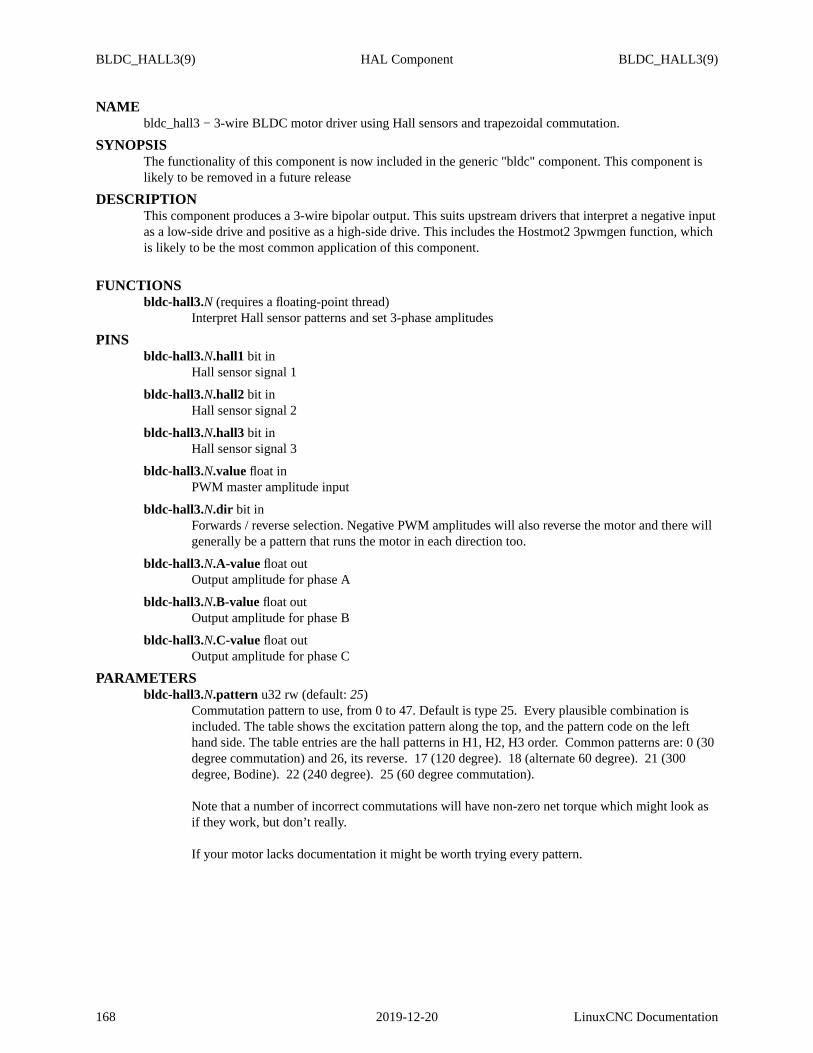
BLDC_HALL3(9) HAL Component BLDC_HALL3(9)
NAMEbldc_hall3 − 3-wire BLDC motor driver using Hall sensors and trapezoidal commutation.
SYNOPSISThe functionality of this component is now included in the generic "bldc" component. This component islikely to be removed in a future release
DESCRIPTIONThis component produces a 3-wire bipolar output. This suits upstream drivers that interpret a negative inputas a low-side drive and positive as a high-side drive. This includes the Hostmot2 3pwmgen function, whichis likely to be the most common application of this component.
FUNCTIONSbldc-hall3.N (requires a floating-point thread)
Interpret Hall sensor patterns and set 3-phase amplitudes
PINSbldc-hall3.N.hall1 bit in
Hall sensor signal 1
bldc-hall3.N.hall2 bit inHall sensor signal 2
bldc-hall3.N.hall3 bit inHall sensor signal 3
bldc-hall3.N.valuefloat inPWM master amplitude input
bldc-hall3.N.dir bit inForwards / reverse selection. Negative PWM amplitudes will also reverse the motor and there willgenerally be a pattern that runs the motor in each direction too.
bldc-hall3.N.A-value float outOutput amplitude for phase A
bldc-hall3.N.B-valuefloat outOutput amplitude for phase B
bldc-hall3.N.C-valuefloat outOutput amplitude for phase C
PARAMETERSbldc-hall3.N.pattern u32 rw (default:25)
Commutation pattern to use, from 0 to 47. Default is type 25. Every plausible combination isincluded. The table shows the excitation pattern along the top, and the pattern code on the lefthand side. The table entries are the hall patterns in H1, H2, H3 order. Common patterns are: 0 (30degree commutation) and 26, its reverse. 17(120 degree). 18(alternate 60 degree). 21(300degree, Bodine). 22 (240 degree). 25(60 degree commutation).
Note that a number of incorrect commutations will have non-zero net torque which might look asif they work, but don’t really.
If your motor lacks documentation it might be worth trying every pattern.
168 2019-12-20 LinuxCNC Documentation
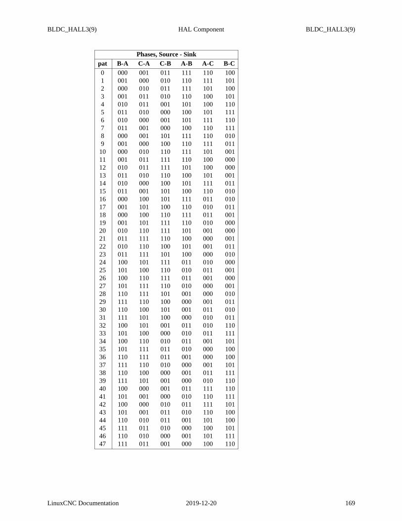
BLDC_HALL3(9) HAL Component BLDC_HALL3(9)
Phases, Source - Sinkpat B-A C-A C-B A-B A-C B-C0 000 001 011 111 110 1001 001 000 010 110 111 1012 000 010 011 111 101 1003 001 011 010 110 100 1014 010 011 001 101 100 1105 011 010 000 100 101 1116 010 000 001 101 111 1107 011 001 000 100 110 1118 000 001 101 111 110 0109 001 000 100 110 111 01110 000 010 110 111 101 00111 001 011 111 110 100 00012 010 011 111 101 100 00013 011 010 110 100 101 00114 010 000 100 101 111 01115 011 001 101 100 110 01016 000 100 101 111 011 01017 001 101 100 110 010 01118 000 100 110 111 011 00119 001 101 111 110 010 00020 010 110 111 101 001 00021 011 111 110 100 000 00122 010 110 100 101 001 01123 011 111 101 100 000 01024 100 101 111 011 010 00025 101 100 110 010 011 00126 100 110 111 011 001 00027 101 111 110 010 000 00128 110 111 101 001 000 01029 111 110 100 000 001 01130 110 100 101 001 011 01031 111 101 100 000 010 01132 100 101 001 011 010 11033 101 100 000 010 011 11134 100 110 010 011 001 10135 101 111 011 010 000 10036 110 111 011 001 000 10037 111 110 010 000 001 10138 110 100 000 001 011 11139 111 101 001 000 010 11040 100 000 001 011 111 11041 101 001 000 010 110 11142 100 000 010 011 111 10143 101 001 011 010 110 10044 110 010 011 001 101 10045 111 011 010 000 100 10146 110 010 000 001 101 11147 111 011 001 000 100 110
LinuxCNC Documentation 2019-12-20 169

BLDC_HALL3(9) HAL Component BLDC_HALL3(9)
SEE ALSObldc_hall6 6-wire unipolar driver for BLDC motors.
AUTHORAndy Pugh
LICENSEGPL
170 2019-12-20 LinuxCNC Documentation

BLEND(9) HAL Component BLEND(9)
NAMEblend − Perform linear interpolation between two values
SYNOPSISloadrt blend [count=N|names=name1[,name2...]]
FUNCTIONSblend.N (requires a floating-point thread)
PINSblend.N.in1 float in
First input. If select is equal to 1.0, the output is equal to in1
blend.N.in2 float inSecond input. If select is equal to 0.0, the output is equal to in2
blend.N.selectfloat inSelect input.For values between 0.0 and 1.0, the output changes linearly from in2 to in1
blend.N.out float outOutput value.
PARAMETERSblend.N.openbit rw
If true, select values outside the range 0.0 to 1.0 give values outside the range in2 to in1. If false,outputs are clamped to the the range in2 to in1
LICENSEGPL
LinuxCNC Documentation 2019-12-20 171

CAROUSEL(9) HAL Component CAROUSEL(9)
NAMEcarousel − Orient a toolchanger carousel using various encoding schemes
SYNOPSISloadrt toolchange pockets=N[,N] encoding=ssss[,sss] num_sense=N[,N] bidirectional=N[,N]
pocketsThe number of pockets in each toolchanger.Use up to 8 numbers separated by commas to create multiple carousel components.
encodingThe position encoding.gray, binary, index or single. Default = ’gray’
num_senseThe number of position sense pins.Default = 4.
dir Set to 1 for unidirectional or2 for bidirectional operation.Default = bidirectional
DESCRIPTIONThis component is intended to help operate various types of carousel-type toolchangers. The componentcan be configured to operate with binary or gray-coded position feedback, with an individual sensor foreach tool position or with a sensor at each tool position and a separate index.
At the moment it is best-suited to Geneva-mechanism type systems where the motor is either on or off.Both unidirectional and bidirectional systems are supported.
The number of carousel component instances created depends on the number of entries in the ’pockets’modparam. For example
loadrt carousel pockets=10,10,8
Would create 3 carousel instances with 10, 10 and 8 pockets. The other parameters are optional. If absentthen defaults will be used. Any missing entry will assume the previous value.
When the enable pin is set to true the component will immediately set the "active" pin to true and then (fora bidirectional instance) calculate the shortest path to the requested pocket number. The appropriate motordirection output pin will then be set.
The component will monitor the carousel position and, when the correct position is reached, set the motor-control pins to 0, set "active" to 0 and set "ready" to 1.
In index mode the behaviour is slightly different the first time that the "enable" pin is set; the carousel willrotate forwards when first enabled until both the index and pulse inputs are true. If there is no pulse line atthe index position then a HAL "or2" function can be used to allow the index sensor to toggle both inputs.Setting "enable" low does not halt the homing move, so if homing on first tool change is not needed thenthe enable pin can be toggled by an axis homing pin or a script.
FUNCTIONScarousel.N
PINScarousel.N.pocket-numbers32 in
The pocket to move to when the .enable pin goes high
carousel.N.enablebit inSet this pin high to start movement. Setting it low will stop movement
172 2019-12-20 LinuxCNC Documentation

CAROUSEL(9) HAL Component CAROUSEL(9)
carousel.N.activebit outindicates that the component is active
carousel.N.ready bit outThis pin goes high when the carousel is in-position
carousel.N.sense-M bit in (M=0..personality)Carousel position feedback pins. In ’index’ mode there will be only 2 pins. sense-0 is the indexand sense-1 is the pocket sensor.
carousel.N.motor-fwd bit outIndicates the motor should run forwards (bigger numbers)
carousel.N.motor-revbit outIndicates the motor should run reverse.
carousel.N.current-position s32 outThis pin indicates the current position feedback
PARAMETERScarousel.N.states32 r (default:0)
Current component state
carousel.N.homing bit r (default:0)Shows that homing is in progress. Only used for index mode
carousel.N.homedbit r (default:0)Shows that homing is complete. Only used in index mode
AUTHORandy pugh
LICENSEGPL
LinuxCNC Documentation 2019-12-20 173

CHARGE_PUMP(9) HAL Component CHARGE_PUMP(9)
NAMEcharge_pump − Create a square-wav efor the ’charge pump’ input of some controller boards
SYNOPSISloadrt charge_pump
DESCRIPTIONThe ’Charge Pump’ should be added to the base thread function. When enabled the output is on for oneperiod and off for one period. To calculate the frequency of the output 1/(period time in seconds x 2) = hz.For example if you have a base period of 100,000ns that is 0.0001 seconds and the formula would be1/(0.0001 x 2) = 5,000 hz or 5 Khz. Two additional outputs are provided that run a factor of 2 and 4 slowerfor hardware that requires a lower frequency.
FUNCTIONScharge-pump
Toggle the output bit (if enabled)
PINScharge-pump.outbit out
Square wav eif ’enable’ is TRUE or unconnected, low if ’ enable’ is FALSE
charge-pump.out-2bit outSquare wav eat half the frequency of ’out’
charge-pump.out-4bit outSquare wav eat a quarter of the frequency of ’out’
charge-pump.enablebit in (default:TRUE)If FALSE, forces all ’out’ pins to be low
LICENSEGPL
174 2019-12-20 LinuxCNC Documentation

CLARKE2(9) HAL Component CLARKE2(9)
NAMEclarke2 − Two input version of Clarke transform
SYNOPSISloadrt clarke2 [count=N|names=name1[,name2...]]
DESCRIPTIONThe Clarke transform can be used to translate a vector quantity from a three phase system (three compo-nents 120 degrees apart) to a two phase Cartesian system.
clarke2 implements a special case of the Clarke transform, which only needs two of the three input phases.In a three wire three phase system, the sum of the three phase currents or voltages must always be zero. Asa result only two of the three are needed to completely define the current or voltage.clarke2 assumes thatthe sum is zero, so it only uses phases A and B of the input. Since the H (homopolar) output will always bezero in this case, it is not generated.
FUNCTIONSclarke2.N (requires a floating-point thread)
PINSclarke2.N.a float inclarke2.N.b float in
first two phases of three phase input
clarke2.N.x float outclarke2.N.y float out
cartesian components of output
SEE ALSOclarke3 for the general case,clarkeinv for the inverse transform.
LICENSEGPL
LinuxCNC Documentation 2019-12-20 175

CLARKE3(9) HAL Component CLARKE3(9)
NAMEclarke3 − Clarke (3 phase to cartesian) transform
SYNOPSISloadrt clarke3 [count=N|names=name1[,name2...]]
DESCRIPTIONThe Clarke transform can be used to translate a vector quantity from a three phase system (three compo-nents 120 degrees apart) to a two phase Cartesian system (plus a homopolar component if the three phasesdon’t sum to zero).
clarke3 implements the general case of the transform, using all three phases. If the three phases are knownto sum to zero, seeclarke2 for a simpler version.
FUNCTIONSclarke3.N (requires a floating-point thread)
PINSclarke3.N.a float inclarke3.N.b float inclarke3.N.c float in
three phase input vector
clarke3.N.x float outclarke3.N.y float out
cartesian components of output
clarke3.N.h float outhomopolar component of output
SEE ALSOclarke2 for the ’a+b+c=0’ case,clarkeinv for the inverse transform.
LICENSEGPL
176 2019-12-20 LinuxCNC Documentation

CLARKEINV(9) HAL Component CLARKEINV(9)
NAMEclarkeinv − Inv erse Clarke transform
SYNOPSISloadrt clarkeinv [count=N|names=name1[,name2...]]
DESCRIPTIONThe inverse Clarke transform can be used rotate a vector quantity and then translate it from Cartesian coor-dinate system to a three phase system (three components 120 degrees apart).
FUNCTIONSclarkeinv.N (requires a floating-point thread)
PINSclarkeinv.N.x float inclarkeinv.N.y float in
cartesian components of input
clarkeinv.N.h float inhomopolar component of input (usually zero)
clarkeinv.N.theta float inrotation angle: 0.00 to 1.00 = 0 to 360 degrees
clarkeinv.N.a float outclarkeinv.N.b float outclarkeinv.N.c float out
three phase output vector
SEE ALSOclarke2 andclarke3 for the forward transform.
LICENSEGPL
LinuxCNC Documentation 2019-12-20 177

CLASSICLADDER(9) HAL Component CLASSICLADDER(9)
NAMEclassicladder − realtime software plc based on ladder logic
SYNOPSISloadrt classicladder_rt [numRungs=N] [numBits=N] [numWords=N] [numTimers=N] [numMonosta-bles=N] [numCounters=N] [numPhysInputs=N] [numPhysOutputs=N] [numArithmExpr= N] [num-Sections=N] [numSymbols=N] [numS32in=N] [numS32out=N] [numFloatIn=N] [numFloatOut=N]
DESCRIPTIONThese pins and parameters are created by the realtimeclassicladder_rtmodule. Each period (minimum1000000 ns), classicladder reads the inputs, evaluates the ladder logic defined in the GUI, and then writesthe outputs.
PINSclassicladder.0.in−NN IN bit
These bit signal pins map to%I NN variables in classicladder
classicladder.0.out−NN OUT bitThese bit signal pins map to%QNN variables in classicladder Output from classicladder
classicladder.0.s32in−NN IN s32Integer input from classicladder These s32 signal pins map to%IW NN variables in classicladder
classicladder.0.s32out−NN OUT s32Integer output from classicladder These s32 signal pins map to%QW NN variables in classiclad-der
classicladder.0.floatin−NN IN floatInteger input from classicladder These float signal pins map to%IF NN variables in classicladderThese are truncated to S32 values internally. eg 7.5 will be 7
classicladder.0.floatout−NN OUT floatFloat output from classicladder These float signal pins map to%QFNN variables in classicladder
classicladder.0.hide_gui IN bitThis bit pin hides the classicladder window, while still having the userspace code run. This is usu-ally desirable when modbus is used, as modbus requires the userspace code to run.
PARAMETERSclassicladder.0.refresh.timeRO s32
Tells you how long the last refresh took
classicladder.0.refresh.tmaxRW s32Tells you how long the longest refresh took
classicladder.0.ladder−stateRO s32Tells you if the program is running or not
FUNCTIONS
178 2008-11-23 LinuxCNC Documentation

CLASSICLADDER(9) HAL Component CLASSICLADDER(9)
classicladder.0.refreshFPThe rung update rate. Add this to the servo thread. You can added it to a faster thread but it Willupdate no faster than once every 1 millisecond (1000000 ns).
BUGSSee http://wiki.linuxcnc.org/cgi−bin/wiki.pl?ClassicLadder_Ver_7.124 for the latest.
SEE ALSOClassicladderchapters in the LinuxCNC documentation for a full description of theClassicladdersyntaxand examples
http://wiki.linuxcnc.org/cgi−bin/wiki.pl?ClassicLadder_Ver_7.124
LinuxCNC Documentation 2008-11-23 179

COMP(9) HAL Component COMP(9)
NAMEcomp − Two input comparator with hysteresis
SYNOPSISloadrt comp [count=N|names=name1[,name2...]]
FUNCTIONScomp.N (requires a floating-point thread)
Update the comparator
PINScomp.N.in0 float in
Inverting input to the comparator
comp.N.in1 float inNon-inverting input to the comparator
comp.N.out bit outNormal output. True whenin1 > in0 (see parameterhyst for details)
comp.N.equalbit outMatch output.True when difference betweenin1 andin0 is less thanhyst/2
PARAMETERScomp.N.hyst float rw (default:0.0)
Hysteresis of the comparator (default 0.0)
With zero hysteresis, the output is true whenin1 > in0. With nonzero hysteresis, the outputswitches on and off at two different values, separated by distancehyst around the point wherein1= in0. Keep in mind that floating point calculations are never absolute and it is wise to always sethyst if you intend to use equal
LICENSEGPL
180 2019-12-20 LinuxCNC Documentation

CONSTANT(9) HAL Component CONSTANT(9)
NAMEconstant − Use a parameter to set the value of a pin
SYNOPSISloadrt constant [count=N|names=name1[,name2...]]
FUNCTIONSconstant.N (requires a floating-point thread)
PINSconstant.N.out float out
PARAMETERSconstant.N.valuefloat rw
LICENSEGPL
LinuxCNC Documentation 2019-12-20 181

CONV_BIT_S32(9) HAL Component CONV_BIT_S32(9)
NAMEconv_bit_s32 − Convert a value from bit to s32
SYNOPSISloadrt conv_bit_s32 [count=N|names=name1[,name2...]]
FUNCTIONSconv-bit-s32.N
Update ’out’ based on ’in’
PINSconv-bit-s32.N.in bit inconv-bit-s32.N.out s32 out
LICENSEGPL
182 2019-12-20 LinuxCNC Documentation

CONV_BIT_U32(9) HAL Component CONV_BIT_U32(9)
NAMEconv_bit_u32 − Convert a value from bit to u32
SYNOPSISloadrt conv_bit_u32 [count=N|names=name1[,name2...]]
FUNCTIONSconv-bit-u32.N
Update ’out’ based on ’in’
PINSconv-bit-u32.N.in bit inconv-bit-u32.N.out u32 out
LICENSEGPL
LinuxCNC Documentation 2019-12-20 183

CONV_FLOAT_S32(9) HAL Component CONV_FLOAT_S32(9)
NAMEconv_float_s32 − Convert a value from float to s32
SYNOPSISloadrt conv_float_s32 [count=N|names=name1[,name2...]]
FUNCTIONSconv-float-s32.N (requires a floating-point thread)
Update ’out’ based on ’in’
PINSconv-float-s32.N.in float inconv-float-s32.N.out s32 outconv-float-s32.N.out-of-rangebit out
TRUE when ’in’ is not in the range of s32
PARAMETERSconv-float-s32.N.clamp bit rw
If TRUE, then clamp to the range of s32. If FALSE, then allow the value to "wrap around".
LICENSEGPL
184 2019-12-20 LinuxCNC Documentation

CONV_FLOAT_U32(9) HAL Component CONV_FLOAT_U32(9)
NAMEconv_float_u32 − Convert a value from float to u32
SYNOPSISloadrt conv_float_u32 [count=N|names=name1[,name2...]]
FUNCTIONSconv-float-u32.N (requires a floating-point thread)
Update ’out’ based on ’in’
PINSconv-float-u32.N.in float inconv-float-u32.N.out u32 outconv-float-u32.N.out-of-rangebit out
TRUE when ’in’ is not in the range of u32
PARAMETERSconv-float-u32.N.clamp bit rw
If TRUE, then clamp to the range of u32. If FALSE, then allow the value to "wrap around".
LICENSEGPL
LinuxCNC Documentation 2019-12-20 185

CONV_S32_BIT(9) HAL Component CONV_S32_BIT(9)
NAMEconv_s32_bit − Convert a value from s32 to bit
SYNOPSISloadrt conv_s32_bit [count=N|names=name1[,name2...]]
FUNCTIONSconv-s32-bit.N
Update ’out’ based on ’in’
PINSconv-s32-bit.N.in s32 inconv-s32-bit.N.out bit outconv-s32-bit.N.out-of-rangebit out
TRUE when ’in’ is not in the range of bit
PARAMETERSconv-s32-bit.N.clamp bit rw
If TRUE, then clamp to the range of bit. If FALSE, then allow the value to "wrap around".
LICENSEGPL
186 2019-12-20 LinuxCNC Documentation

CONV_S32_FLOAT(9) HAL Component CONV_S32_FLOAT(9)
NAMEconv_s32_float − Convert a value from s32 to float
SYNOPSISloadrt conv_s32_float [count=N|names=name1[,name2...]]
FUNCTIONSconv-s32-float.N (requires a floating-point thread)
Update ’out’ based on ’in’
PINSconv-s32-float.N.in s32 inconv-s32-float.N.out float out
LICENSEGPL
LinuxCNC Documentation 2019-12-20 187

CONV_S32_U32(9) HAL Component CONV_S32_U32(9)
NAMEconv_s32_u32 − Convert a value from s32 to u32
SYNOPSISloadrt conv_s32_u32 [count=N|names=name1[,name2...]]
FUNCTIONSconv-s32-u32.N
Update ’out’ based on ’in’
PINSconv-s32-u32.N.in s32 inconv-s32-u32.N.out u32 outconv-s32-u32.N.out-of-rangebit out
TRUE when ’in’ is not in the range of u32
PARAMETERSconv-s32-u32.N.clamp bit rw
If TRUE, then clamp to the range of u32. If FALSE, then allow the value to "wrap around".
LICENSEGPL
188 2019-12-20 LinuxCNC Documentation

CONV_U32_BIT(9) HAL Component CONV_U32_BIT(9)
NAMEconv_u32_bit − Convert a value from u32 to bit
SYNOPSISloadrt conv_u32_bit [count=N|names=name1[,name2...]]
FUNCTIONSconv-u32-bit.N
Update ’out’ based on ’in’
PINSconv-u32-bit.N.in u32 inconv-u32-bit.N.out bit outconv-u32-bit.N.out-of-rangebit out
TRUE when ’in’ is not in the range of bit
PARAMETERSconv-u32-bit.N.clamp bit rw
If TRUE, then clamp to the range of bit. If FALSE, then allow the value to "wrap around".
LICENSEGPL
LinuxCNC Documentation 2019-12-20 189

CONV_U32_FLOAT(9) HAL Component CONV_U32_FLOAT(9)
NAMEconv_u32_float − Convert a value from u32 to float
SYNOPSISloadrt conv_u32_float [count=N|names=name1[,name2...]]
FUNCTIONSconv-u32-float.N (requires a floating-point thread)
Update ’out’ based on ’in’
PINSconv-u32-float.N.in u32 inconv-u32-float.N.out float out
LICENSEGPL
190 2019-12-20 LinuxCNC Documentation

CONV_U32_S32(9) HAL Component CONV_U32_S32(9)
NAMEconv_u32_s32 − Convert a value from u32 to s32
SYNOPSISloadrt conv_u32_s32 [count=N|names=name1[,name2...]]
FUNCTIONSconv-u32-s32.N
Update ’out’ based on ’in’
PINSconv-u32-s32.N.in u32 inconv-u32-s32.N.out s32 outconv-u32-s32.N.out-of-rangebit out
TRUE when ’in’ is not in the range of s32
PARAMETERSconv-u32-s32.N.clamp bit rw
If TRUE, then clamp to the range of s32. If FALSE, then allow the value to "wrap around".
LICENSEGPL
LinuxCNC Documentation 2019-12-20 191

COUNTER(9) HAL Component COUNTER(9)
NAMEcounter − counts input pulses(DEPRECATED)
SYNOPSISloadrt counter [num_chan=N]
DESCRIPTIONcounter is a deprecated HAL component and will be removed in a future release. Use theencodercompo-nent with encoder.X.counter−mode set to TRUE.
counter is a HAL component that provides software- based counting that is useful for spindle positionsensing and maybe other things. Instead of using a real encoder that outputs quadrature, some lathes have asensor that generates a simple pulse stream as the spindle turns and an index pulse once per revolution.This component simply counts up when a "count" pulse (phase−A) is received, and if reset is enabled,resets when the "index" (phase−Z) pulse is received.
This is of course only useful for a unidirectional spindle, as it is not possible to sense the direction of rota-tion.
counter conforms to the "canonical encoder" interface described in the HAL manual.
FUNCTIONScounter.capture−position(uses floating-point)
Updates the counts, position and velocity outputs based on internal counters.
counter.update−countersSamples the phase−A and phase−Z inputs and updates internal counters.
PINScounter.N.phase−Abit in
The primary input signal. The internal counter is incremented on each rising edge.
counter.N.phase−Zbit inThe index input signal. When theindex−enablepin is TRUE and a rising edge onphase−Zisseen,index−enableis set to FALSE and the internal counter is reset to zero.
counter.N.index−enablebit iocounter.N.resetbit iocounter.N.countssigned outcounter.N.position float outcounter.N.velocity float out
These pins function according to the canonical digital encoder interface.
counter.N.position−scalefloat rwThis parameter functions according to the canonical digital encoder interface.
counter.N.rawcountssigned roThe internal counts value, updated fromupdate−countersand reflected in the output pins at thenext call tocapture−position.
SEE ALSOencoder(9). in the LinuxCNC documentation.
192 2007-01-19 LinuxCNC Documentation

DDT(9) HAL Component DDT(9)
NAMEddt − Compute the derivative of the input function
SYNOPSISloadrt ddt [count=N|names=name1[,name2...]]
FUNCTIONSddt.N (requires a floating-point thread)
PINSddt.N.in float inddt.N.out float out
LICENSEGPL
LinuxCNC Documentation 2019-12-20 193

DEADZONE(9) HAL Component DEADZONE(9)
NAMEdeadzone − Return the center if within the threshold
SYNOPSISloadrt deadzone [count=N|names=name1[,name2...]]
FUNCTIONSdeadzone.N (requires a floating-point thread)
Updateout based onin and the parameters.
PINSdeadzone.N.in float indeadzone.N.out float out
PARAMETERSdeadzone.N.centerfloat rw (default:0.0)
The center of the dead zone
deadzone.N.threshhold float rw (default:1.0)The dead zone iscenter ± (threshhold/2)
LICENSEGPL
194 2019-12-20 LinuxCNC Documentation

DEBOUNCE(9) HAL Component DEBOUNCE(9)
NAMEdebounce − filter noisy digital inputs
SYNOPSISloadrt debounce cfg=size[,size,...]
Creates debounce groups with the number of filters specified by (size). Every filter in the same group hasthe same sample rate and delay. For example cfg=2,3 creates two filter groups with 2 filters in the firstgroup and 3 filters in the second group.
DESCRIPTIONThe debounce filter works by incrementing a counter whenever the input is true, and decrementing thecounter when it is false. Ifthe counter decrements to zero, the output is set false and the counter ignoresfurther decrements. If the counter increments up to a threshold, the output is set true and the counterignores further increments. If the counter is between zero and the threshold, the output retains its previousstate. Thethreshold determines the amount of filtering: a threshold of 1 does no filtering at all, and athreshold of N requires a signal to be present for N samples before the output changes state.
FUNCTIONSdebounce.G
Sample all the input pins in group G and update the output pins.
PINSdebounce.G.F.in bit in
The F’th input pin in group G.
debounce.G.F.out bit outThe F’th output pin in group G. Reflects the last "stable" input seen on the corresponding inputpin.
debounce.G.delaysigned rwSets the amount of filtering for all pins in group G.
LinuxCNC Documentation 2007-01-16 195

EDGE(9) HAL Component EDGE(9)
NAMEedge − Edge detector
SYNOPSISloadrt edge [count=N|names=name1[,name2...]]
FUNCTIONSedge.N Produce output pulses from input edges
PINSedge.N.in bit inedge.N.out bit out
Goes high when the desired edge is seen on ’in’
edge.N.out-invert bit outGoes low when the desired edge is seen on ’in’
PARAMETERSedge.N.both bit rw (default:FALSE)
If TRUE, selects both edges. Otherwise, selects one edge according to in-edge
edge.N.in-edgebit rw (default:TRUE)If both is FALSE, selects the one desired edge: TRUE means falling, FALSE means rising
edge.N.out-width-ns s32 rw (default:0)Time in nanoseconds of the output pulse
edge.N.time-left-ns s32 rTime left in this output pulse
edge.N.last-in bit rPrevious input value
LICENSEGPL
196 2019-12-20 LinuxCNC Documentation
ENCODER(9) HAL Component ENCODER(9)
NAMEencoder − software counting of quadrature encoder signals
SYNOPSISloadrt encoder [num_chan=num| names=name1[,name2...]]
DESCRIPTIONencoderis used to measure position by counting the pulses generated by a quadrature encoder. As a soft-ware-based implementation it is much less expensive than hardware, but has a limited maximum count rate.The limit is in the range of 10KHz to 50KHz, depending on the computer speed and other factors. Ifbetterperformance is needed, a hardware encoder counter is a better choice. Some hardware-based systems cancount at MHz rates.
encodersupports a maximum of eight channels. The number of channels actually loaded is set by thenum_chanargument when the module is loaded. Alternatively, specify names= and unique names sepa-rated by commas.
Thenum_chan=andnames=specifiers are mutually exclusive. If neithernum_chan=nornames=arespecified, or ifnum_chan=0is specified, the default value is three.
encoderhas a one-phase, unidirectional mode calledcounter. In this mode, thephase−Binput is ignored;the counts increase on each rising edge ofphase−A. This mode may be useful for counting a unidirec-tional spindle with a single input line, though the noise-resistant characteristics of quadrature are lost.
FUNCTIONSencoder.update−counters(no floating-point)
Does the actual counting, by sampling the encoder signals and decoding the quadrature wav e-forms. Mustbe called as frequently as possible, preferably twice as fast as the maximum desiredcount rate. Operates on all channels at once.
encoder.capture−position(uses floating point)Captures the raw counts fromupdate−countersand performs scaling and other necessary conver-sion, handles counter rollover, etc. Can(and should) be called less frequently thanupdate−coun-ters. Operates on all channels at once.
NAMINGThe names for pins and parameters are prefixed as:encoder.N.for N=0,1,...,num−1 when usingnum_chan=numnameN.for nameN=name1,name2,... when usingnames=name1,name2,...
Theencoder.N.format is shown in the following descriptions.
PINSencoder.N.counter−modebit i/o
Enables counter mode. When true, the counter counts each rising edge of the phase−A input,ignoring the value on phase−B. This is useful for counting the output of a single channel (non-quadrature) sensor. When false (the default), it counts in quadrature mode.
encoder.N.countss32 outPosition in encoder counts.
encoder.N.index−enablebit i/oWhen true,countsandposition are reset to zero on the next rising edge ofPhase−Z. At the sametime, index−enableis reset to zero to indicate that the rising edge has occurred.
LinuxCNC Documentation 2009-04-15 197

ENCODER(9) HAL Component ENCODER(9)
encoder.N.min−speed−estimatefloat in (default: 1.0)Determine the minimum speed at whichvelocity will be estimated as nonzero andposti-tion−interpolated will be interpolated. The units ofmin−speed−estimateare the same as theunits ofvelocity. Setting this parameter too low will cause it to take a long time forvelocity to goto 0 after encoder pulses have stopped arriving.
encoder.N.phase−Abit inQuadrature input for encoder channelN.
encoder.N.phase−Bbit inQuadrature input.
encoder.N.phase−Zbit inIndex pulse input.
encoder.N.position float outPosition in scaled units (seeposition−scale)
encoder.N.position−interpolated float outPosition in scaled units, interpolated between encoder counts. Only valid when velocity is approx-imately constant and abovemin−speed−estimate. Do not use for position control.
encoder.N.position−scalefloat i/oScale factor, in counts per length unit.For example, ifposition−scaleis 500, then 1000 counts ofthe encoder will be reported as a position of 2.0 units.
encoder.N.rawcountss32 outThe raw count, as determined byupdate−counters. This value is updated more frequently thancountsandposition. It is also unaffected byresetor the index pulse.
encoder.N.resetbit inWhen true,countsandposition are reset to zero immediately.
encoder.N.velocity float outVelocity in scaled units per second.encoderuses an algorithm that greatly reduces quantizationnoise as compared to simply differentiating theposition output. Whenthe magnitude of the truevelocity is below min−speed−estimate, the velocity output is 0.
encoder.N.x4−modebit i/oEnables times−4 mode. When true (the default), the counter counts each edge of the quadraturewaveform (four counts per full cycle). Whenfalse, it only counts once per full cycle. Incounter−mode, this parameter is ignored.
encoder.N.latch−input bit inencoder.N.latch−falling bit in (default:TRUE)encoder.N.latch−rising bit in (default:TRUE)encoder.N.counts−latcheds32 outencoder.N.position−latchedfloat out
Updatecounts−latchedandposition−latchedon the rising and/or falling edges oflatch−input asindicated bylatch−rising andlatch−falling .
encoder.N.counter−modebit rwEnables counter mode. When true, the counter counts each rising edge of the phase−A input,ignoring the value on phase−B. This is useful for counting the output of a single channel (non-quadrature) sensor. When false (the default), it counts in quadrature mode.encoder.N.cap-ture−position.tmax s32 rw Maximum number of CPU cycles it took to execute this function.
PARAMETERSThe encoder component has no HAL Parameters.
198 2009-04-15 LinuxCNC Documentation

ENCODER(9) HAL Component ENCODER(9)
LinuxCNC Documentation 2009-04-15 199

ENCODER_RATIO(9) HAL Component ENCODER_RATIO(9)
NAMEencoder_ratio − an electronic gear to synchronize two axes
SYNOPSISloadrt encoder_ratio [num_chan=num| names=name1[,name2...]]
DESCRIPTIONencoder_ratiocan be used to synchronize two axes (like an "electronic gear"). It counts encoder pulsesfrom both axes in software, and produces an error value that can be used with a PID loop to make the slaveencoder track the master encoder with a specific ratio.
This module supports up to eight axis pairs. The number of pairs is set by the module parameternum_chan. Alternatively, specifynames=and unique names separated by commas.
Thenum_chan=andnames=specifiers are mutually exclusive. If neithernum_chan=nornames=arespecified, the default value is one.
FUNCTIONSencoder−ratio.sample
Read all input pins. Must be called at twice the maximum desired count rate.
encoder−ratio.update (uses floating-point)Updates all output pins. May be called from a slower thread.
NAMINGThe names for pins and parameters are prefixed as:encoder−ratio.N.for N=0,1,...,num−1 when usingnum_chan=numnameN.for nameN=name1,name2,... when usingnames=name1,name2,...
Theencoder−ratio.N.format is shown in the following descriptions.
PINSencoder−ratio.N.master−A bit inencoder−ratio.N.master−Bbit inencoder−ratio.N.slave−A bit inencoder−ratio.N.slave−B bit in
The encoder channels of the master and slave axes
encoder−ratio.N.enablebit inWhen the enable pin is FALSE, the error pin simply reports the slave axis position, in revolutions.As such, it would normally be connected to the feedback pin of a PID block for closed loop con-trol of the slave axis. Normallythe command input of the PID block is left unconnected (zero), sothe slave axis simply sits still. However when the enable input goes TRUE, the error pin becomesthe slave position minus the scaled master position. The scale factor is the ratio of master teeth toslave teeth. Asthe master moves, error becomes non-zero, and the PID loop will drive the slaveaxis to track the master.
encoder−ratio.N.error float outThe error in the position of the slave (in revolutions)
PARAMETERSencoder−ratio.N.master−pprunsigned rwencoder−ratio.N.slave−ppr unsigned rw
The number of pulses per revolution of the master and slave axes
200 2007-01-16 LinuxCNC Documentation

ENCODER_RATIO(9) HAL Component ENCODER_RATIO(9)
encoder−ratio.N.master−teethunsigned rwencoder−ratio.N.slave−teethunsigned rw
The number of "teeth" on the master and slave gears.
SEE ALSOencoder(9)
LinuxCNC Documentation 2007-01-16 201

ESTOP_LATCH(9) HAL Component ESTOP_LATCH(9)
NAMEestop_latch − Software ESTOP latch
SYNOPSISloadrt estop_latch [count=N|names=name1[,name2...]]
DESCRIPTIONThis component can be used as a part of a simple software ESTOP chain.
It has two states: "OK" and "Faulted".
The initial state is "Faulted". Whenfaulted, theout-ok output is false, thefault-out output is true, and thewatchdogoutput is unchanging.
The state changes from "Faulted" to "OK" whenall these conditions are true:
• fault-in is false
• ok-in is true
• resetchanges from false to true
When "OK", theout-ok output is true, thefault-out output is false, and thewatchdogoutput is toggling.
The state changes from "OK" to "Faulted" whenany of the following are true:
• fault-in is true
• ok-in is false
To facilitate using only a single fault source,ok-in andfault-en are both set to the non-fault-causing valuewhen no signal is connected.For estop-latch to ever be able to signal a fault, at least one of these inputsmust be connected.
Typically, an external fault or estop input is connected tofault-in , iocontrol.0.user-request-enableis con-nected toreset, andok-out is connected toiocontrol.0.emc-enable-in.
In more complex systems, it may be more appropriate to use classicladder to manage the softwareportion of the estop chain.
FUNCTIONSestop-latch.N
PINSestop-latch.N.ok-in bit in (default:true)estop-latch.N.fault-in bit in (default:false)estop-latch.N.resetbit inestop-latch.N.ok-out bit out (default:false)estop-latch.N.fault-out bit out (default:true)estop-latch.N.watchdogbit out
LICENSEGPL
202 2019-12-20 LinuxCNC Documentation

FEEDCOMP(9) HAL Component FEEDCOMP(9)
NAMEfeedcomp − Multiply the input by the ratio of current velocity to the feed rate
SYNOPSISloadrt feedcomp [count=N|names=name1[,name2...]]
FUNCTIONSfeedcomp.N (requires a floating-point thread)
PINSfeedcomp.N.out float out
Proportionate output value
feedcomp.N.in float inReference value
feedcomp.N.enablebit inTurn compensation on or off
feedcomp.N.vel float inCurrent velocity
PARAMETERSfeedcomp.N.feedfloat rw
Feed rate reference value
NOTESNote that if enable is false, out = in
LICENSEGPL
LinuxCNC Documentation 2019-12-20 203

FLIPFLOP(9) HAL Component FLIPFLOP(9)
NAMEflipflop − D type flip-flop
SYNOPSISloadrt flipflop [count= N|names=name1[,name2...]]
FUNCTIONSflipflop.N
PINSflipflop.N.data bit in
data input
flipflop.N.clk bit inclock, rising edge writes data to out
flipflop.N.setbit inwhen true, force out true
flipflop.N.resetbit inwhen true, force out false; overrides set
flipflop.N.out bit iooutput
LICENSEGPL
204 2019-12-20 LinuxCNC Documentation

GANTRY(9) HAL Component GANTRY(9)
NAMEgantry − LinuxCNC HAL component for driving multiple joints from a single axis
SYNOPSISloadrt gantry [count=N|names=name1[,name2...]] [personality=P,P,...]
DESCRIPTIONDrives multiple physical motors (joints) from a single axis input
The ‘personality’ value is the number of joints to control.Tw o is typical, but up to seven is supported (athree joint setup has been tested with hardware).
All controlled joints track the commanded position (with a per-joint offset) unless in the process of homing.Homing is when the commanded position is moving towards the homing switches (as determined by thesign of search-vel) and the joint home switches are not all in the same state. When the system is homingand a joint home switch activates, the command value sent to that joint is "frozen" and the joint offset valueis updated instead. Once all home switches are active, there are no more adjustments made to the offsetvalues and all joints run in lock-step once more.
For best results, set HOME_SEARCH_VEL and HOME_LATCH_VEL to the same direction and as slowas practical. When a joint home switch trips, the commanded velocity will drop immediately fromHOME_SEARCH_VEL to zero, with no limit on acceleration.
FUNCTIONSgantry.N.read (requires a floating-point thread)
Update position-fb and home/limit outputs based on joint values
gantry.N.write (requires a floating-point thread)Update joint pos-cmd outputs based on position-cmd in
PINSgantry.N.joint.MM.pos-cmdfloat out (MM=00..personality)
Per-joint commanded position
gantry.N.joint.MM.pos-fbfloat in (MM=00..personality)Per-joint position feedback
gantry.N.joint.MM.homebit in (MM=00..personality)Per-joint home switch
gantry.N.joint.MM.offsetfloat out (MM=00..personality)(debugging) Per-joint offset value, updated when homing
gantry.N.position-cmdfloat inCommanded position from motion
gantry.N.position-fb float outPosition feedback to motion
gantry.N.homebit outCombined home signal, true if all joint home inputs are true
gantry.N.limit bit outCombined limit signal, true if any joint home input is true
gantry.N.search-velfloat inHOME_SEARCH_VEL from ini file
LICENSEGPL
LinuxCNC Documentation 2019-12-20 205

GANTRYKINS(9) HAL Component GANTRYKINS(9)
NAMEgantrykins − A kinematics module that maps one axis to multiple joints
SYNOPSISloadrt gantrykins coordinates=axisletters
Specifying gantry joint mapping via loadrtThecoordinates=parameter specifies the initial gantry joint mapping. Each axis letter is mapped to ajoint, starting from 0. Socoordinates=XYYZ maps the X axis to joint 0, the Y axis to joint 1 and 2, andthe Z axis to joint 3. If not specified, the default mapping iscoordinates=XYZABC. Coordinate lettersmay be specified in uppercase or lowercase.
A note about joints and axesLinuxCNC makes a distinction between joints and axes: a joint is something controlled by a motor, and anaxis is a coordinate you can move via G-code.You can also jog joints or jog axes.
A gantry has two joints controlling one axis, and this requires a bit of special care.
Homing always happens in joint mode (aka Free mode). The two joints of a gantry’s axis must be homedtogether, so they must have the same [AXIS_n]HOME_SEQUENCE in the .ini file.
Jogging of a gantry must happen in world mode (aka Teleop mode). If you jog a gantry in joint mode (Freemode), you will move just one of the joints, and the gantry will rack. In contrast, if you jog a gantry inworld mode (Teleop mode), it’s the axis that jogs: linuxcnc will coordinate the motion of the two joints thatmake up the axis, both joints will move together, and the gantry will stay square.
The Axis GUI has provisions for jogging in joint mode (Free) and in world mode (Teleop). Usethe "$"hotkey, or the View menu to switch between them.
Joint-mode (aka Free mode) supports continuous and incremental jogging.World-mode (aka Teleop mode)only supports continuous jogging.
KINEMATICSIn the inverse kinematics, each joint gets the value of its corresponding axis. In the forward kinematics,each axis gets the value of the highest numbered corresponding joint.For example, withcoordi-nates=XYYZ the Y axis position comes from joint 2, not joint 1.
FUNCTIONSNone.
PINSNone.
PARAMETERSgantrykins.joint− N (s32)
Specifies the axis mapped to jointN. The values 0 through 8 correspond to the axes XYZ-ABCUVW. It is preferable to use the "coordinates=" parameter at loadrt-time rather than settingthe joint−N parameters later, because the gantrykins module prints the joint-to-axis mapping atloadrt-time, and having that output correct is nice.
206 2010-10-12 LinuxCNC Documentation

GANTRYKINS(9) HAL Component GANTRYKINS(9)
NOTESgantrykins must be loaded beforemotion.
SEE ALSOKinematicssection in the LinuxCNC documentation
LICENSEGPL
LinuxCNC Documentation 2010-10-12 207

GEARCHANGE(9) HAL Component GEARCHANGE(9)
NAMEgearchange − Select from one two speed ranges
SYNOPSISThe output will be a value scaled for the selected gear, and clamped to the min/max values for that gear.The scale of gear 1 is assumed to be 1, so the output device scale should be chosen accordingly. The scaleof gear 2 is relative to gear 1, so if gear 2 runs the spindle 2.5 times as fast as gear 1, scale2 should be set to2.5.
FUNCTIONSgearchange.N (requires a floating-point thread)
PINSgearchange.N.selbit in
Gear selection input
gearchange.N.speed-infloat inSpeed command input
gearchange.N.speed-outfloat outSpeed command to DAC/PWM
gearchange.N.dir-in bit inDirection command input
gearchange.N.dir-out bit outDirection output - possibly inverted for second gear
PARAMETERSgearchange.N.min1 float rw (default:0)
Minimum allowed speed in gear range 1
gearchange.N.max1float rw (default:100000)Maximum allowed speed in gear range 1
gearchange.N.min2 float rw (default:0)Minimum allowed speed in gear range 2
gearchange.N.max2float rw (default:100000)Maximum allowed speed in gear range 2
gearchange.N.scale2float rw (default:1.0)Relative scale of gear 2 vs. gear 1 Since it is assumed that gear 2 is "high gear",scale2must begreater than 1, and will be reset to 1 if set lower.
gearchange.N.rev ersebit rw (default:0)Set to 1 to reverse the spindle in second gear
LICENSEGPL
208 2019-12-20 LinuxCNC Documentation

gladevcp(9) HAL Component gladevcp(9)
NAMEgladevcp − displays Virtual control Panels built with GTK / GLADE
SYNOPSISloadusr gladevcp [−c componentname0xN] [−g WxH+Xoffset+Yoffset0xN] [−H halcmdfile] [−x win-dowid] gladefile.glade
DESCRIPTIONgladevcp parses a glade file and displays the widgets in a window. Then calls gladevcp_makepins whichagain parses the gladefile looking for specific HAL widgets then makes HAL pins and sets up updating forthem. TheHAL component name defaults to the basename of the glade file. The −x option directs glade-vcp to reparent itself under this X window id instead of creating its own toplevel window. The −H optionpasses an input file for halcmd to be run after the gladevcp component is initialized. This is used in Axiswhen running gladevcp under a tab with the EMBED_TAB_NAME/EMBED_TAB_COMMAND ini filefeature.
gladevcp supports gtkbuilder or libglade files though some widgets are not fully supported in gtkbuilderyet.
ISSUESFor now system links need to be added in the glade library folders to point to our new widgets and catalogfiles. look in lib/python/gladevcp/READ_ME for details
LinuxCNC Documentation 2010-08-24 209

GRAY2BIN(9) HAL Component GRAY2BIN(9)
NAMEgray2bin − convert a gray-code input to binary
SYNOPSISloadrt gray2bin [count=N|names=name1[,name2...]]
DESCRIPTIONConverts a gray-coded number into the corresponding binary value
FUNCTIONSgray2bin.N
PINSgray2bin.N.in u32 in
gray code in
gray2bin.N.out u32 outbinary code out
AUTHORandy pugh
LICENSEGPL
210 2019-12-20 LinuxCNC Documentation

HISTOBINS(9) HAL Component HISTOBINS(9)
NAMEhistobins − histogram bins utility for scripts/hal-histogram
SYNOPSISUsage:Read availablebins pin for the number of bins available.Set the minvalue, binsize, and nbins pins.Ensure nbins <= availablebinsFor nbins = N, the bins are numbered: 0 ... N−1
Iterate:Set index pin to a bin number: 0 <= index < nbins.Read check pin and verify that check pin == index pin.Read outputs: binvalue, pextra, nextra pins.
(binvalue is count for the indexed bin)(pextra iscount for all inputs > maxvalue)(nextra iscount for all bins < minvalue)
If index is out of range (index < 0 or index > maxbinnumber)then binvalue == −1.The input-error pin is set when input rules are violatedand updates cease.The reset pin may be used to restart.The input used is selected based on pintype:pintype inputpin------- -----------
0 input1 input-s322 input-u323 input-bit
Additional output statistics pins:input-mininput-maxnsamplesvariancemean
The method input pin selects an alternate variance calculation.
Maintainers note: hardcoded for MAXBINNUMBER==200
FUNCTIONShistobins.N (requires a floating-point thread)
PINShistobins.N.pintype u32 inhistobins.N.input float inhistobins.N.input-s32s32 inhistobins.N.input-u32 u32 inhistobins.N.input-bit bit inhistobins.N.nbins u32 in (default:20)histobins.N.binsizefloat in (default:1)histobins.N.minvalue float in (default:0)histobins.N.index s32 in
LinuxCNC Documentation 2019-12-20 211

HISTOBINS(9) HAL Component HISTOBINS(9)
histobins.N.checks32 outhistobins.N.resetbit inhistobins.N.methodbit inhistobins.N.input-error bit outhistobins.N.binvalue float outhistobins.N.pextra float outhistobins.N.nextra float outhistobins.N.input-min float outhistobins.N.input-max float outhistobins.N.nsamplesu32 outhistobins.N.variancefloat outhistobins.N.meanfloat outhistobins.N.availablebins s32 out (default:200)
LICENSEGPL
212 2019-12-20 LinuxCNC Documentation

HM2_7I43(9) HAL Component HM2_7I43(9)
NAMEhm2_7i43 − LinuxCNC HAL driver for the Mesa Electronics 7i43 EPP Anything IO board with HostMot2firmware.
SYNOPSISloadrt hm2_7i43 [ioaddr=N[,N...]] [ioaddr_hi=N[,N...]] [epp_wide=N[,N...]] [config="str[,str...]" ]
[debug_epp=N[,N...]]
ioaddr [default: 0x378]The base address of the parallel port.
ioaddr_hi [default: 0]The secondary address of the parallel port, used to set EPP mode.0 means to use ioaddr +0x400.
epp_wide[default: 1]Set to zero to disable the "wide EPP mode". "Wide" mode allows a 16- and 32-bit EPP trans-fers, which can reduce the time spent in the read and write functions. However, this may notwork on all EPP parallel ports.
config [default: ""]HostMot2 config strings, described in the hostmot2(9) manpage.
debug_epp[default: 0]Developer/debug use only! Enable debug logging of most EPP transfers.
DESCRIPTIONhm2_7i43 is a device driver that interfaces the Mesa 7i43 board with the HostMot2 firmware to the Linux-CNC HAL. Both the 200K and the 400K FPGAs are supported.
The driver talks with the 7i43 over the parallel port, not over USB. USBcan be used to power the 7i43, butnot to talk to it. USB communication with the 7i43 will not be supported any time soon, since USB haspoor real-time qualities.
The driver programs the board’s FPGA with firmware when it registers the board with the hostmot2 driver.The firmware to load is specified in theconfigmodparam, as described in the hostmot2(9) manpage, in theconfig modparamsection.
Jumper settingsTo send the FPGA configuration from the PC, the board must be configured to get its firmware from theEPP port.To do this, jumpers W4 and W5 must both be down, ie toward the USB connector.
The board must be configured to power on whether or not the USB interface is active. This is done by set-ting jumper W7 up, ie away from the edge of the board.
Communicating with the boardThe 7i43 communicates with the LinuxCNC computer over EPP, the Enhanced Parallel Port. This providesabout 1 MBps of throughput, and the communication latency is very predictable and reasonably low.
The parallel port must support EPP 1.7 or EPP 1.9. EPP 1.9 is prefered, but EPP 1.7 will work too. TheEPP mode of the parallel port is sometimes a setting in the BIOS.
Note that the popular "NetMOS" aka "MosChip 9805" PCI parport cardsdo not work. They do not meetthe EPP spec, and cannot be reliably used with the 7i43.You hav eto find another card, sorry.
EPP is very reliable under normal circumstances, but bad cabling or excessively long cabling runs maycause communication timeouts. The driver exports a parameter named hm2_7i43.<BoardNum>.io_error toinform HAL of this condition. When the driver detects an EPP timeout, it sets io_error to True and stopscommunicating with the 7i43 board. Setting io_error back to False makes the driver start trying to
LinuxCNC Documentation 2008-05-13 213

HM2_7I43(9) HAL Component HM2_7I43(9)
communicate with the 7i43 again.
Access to the EPP bus is not threadsafe: only one realtime thread may access the EPP bus.
SEE ALSOhostmot2(9)
LICENSEGPL
214 2008-05-13 LinuxCNC Documentation

HM2_7I90(9) HAL Component HM2_7I90(9)
NAMEhm2_7i90 − LinuxCNC HAL driver for the Mesa Electronics 7i90 EPP Anything IO board with HostMot2firmware.
SYNOPSISloadrt hm2_7i90 [ioaddr=N[,N...]] [ioaddr_hi=N[,N...]] [epp_wide=N[,N...]] [debug_epp=N[,N...]]
ioaddr [default: 0x378]The base address of the parallel port.
ioaddr_hi [default: 0]The secondary address of the parallel port, used to set EPP mode.0 means to use ioaddr +0x400.
epp_wide[default: 1]Set to zero to disable the "wide EPP mode". "Wide" mode allows a 16- and 32-bit EPP trans-fers, which can reduce the time spent in the read and write functions. However, this may notwork on all EPP parallel ports.
debug_epp[default: 0]Developer/debug use only! Enable debug logging of most EPP transfers.
DESCRIPTIONhm2_7i90 is a device driver that interfaces the Mesa 7i90 board with the HostMot2 firmware to the Linux-CNC HAL.
The 7i90 firmware is stored on the 7i90 itself, it is not programmed by the driver at load time. The 7i90firmware can be changed using the mesaflash program.
The driver talks with the 7i90 over the parallel port, via EPP.
Communicating with the boardThe 7i90 communicates with the LinuxCNC computer over EPP, the Enhanced Parallel Port. This providesabout 1 MBps of throughput, and the communication latency is very predictable and reasonably low.
The parallel port must support EPP 1.7 or EPP 1.9. EPP 1.9 is prefered, but EPP 1.7 will work too. TheEPP mode of the parallel port is sometimes a setting in the BIOS.
Note that the popular "NetMOS" aka "MosChip 9805" PCI parport cardsdo not work. They do not meetthe EPP spec, and cannot be reliably used with the 7i90.You hav eto find another card, sorry.
EPP is very reliable under normal circumstances, but bad cabling or excessively long cabling runs maycause communication timeouts. The driver exports a parameter named hm2_7i90.<BoardNum>.io_error toinform HAL of this condition. When the driver detects an EPP timeout, it sets io_error to True and stopscommunicating with the 7i90 board. Setting io_error back to False makes the driver start trying to commu-nicate with the 7i90 again.
Access to the EPP bus is not threadsafe: only one realtime thread may access the EPP bus.
SEE ALSOhostmot2(9)
LICENSEGPL
LinuxCNC Documentation 2013-10-27 215

HM2_ETH(9) HAL Component HM2_ETH(9)
NAMEhm2_eth − LinuxCNC HAL driver for the Mesa Electronics Ethernet Anything IO boards, with HostMot2firmware.
SYNOPSISloadrt hm2_eth [config="str[,str...]" ] [board_ip=ip[,ip...] ] [board_mac=mac[,mac...]]
config [default: ""]HostMot2 config strings, described in the hostmot2(9) manpage.
board_ip [default: ""]The IP address of the board(s), separated by commas. As shipped, the board address is192.168.1.121.
DESCRIPTIONhm2_eth is a device driver that interfaces Mesa’s ethernet based Anything I/O boards (with the HostMot2firmware) to the LinuxCNC HAL.
The supported boards are: 7i76E, 7I80DB, 7I80HD, 7i92, 7i93.
The board must have its hardware loaded on the board by the mesaflash(1) program.
hm2_eth is only available when linuxcnc is configured with "uspace" realtime.
INTERFACE CONFIGURATIONhm2_eth should be used on a dedicated network interface, with only a cable between the PC and the board.Wireless and USB network interfaces are not suitable.
These instructions assume your dedicated network interface is "eth1", 192.168.1/24 is an unused privatenetwork, that the hostmot2 board is using the default address of 192.168.1.121, that you are using Debian 7or similar, and that you do not otherwise use iptables. If any of these are false, you will need to modify theinstructions accordingly. After following all the instructions, reboot so that the changes take effect.
It is particularly important to check that the network 192.168.1/24 is not already the private network usedby your internet router, because this is a commonly-used value. Ifyou use another network, you will alsoneed to reconfigure the hostmot2 card to use an IP address on that network by using the mesaflash(1) utilityand change jumper settings.Typically, you will choose one of the networks in the Private IPv4 addressspace.⟨http://en.wikipedia.org/wiki/IPv4#Private_networks⟩ One common alternative is PC address10.10.10.1, hostmot2 address 10.10.10.10.
Use of the dedicated ethernet interface while linuxcnc is running can cause violation of realtime guarantees.hm2_eth will automatically mitigate most accidental causes of interference.
Configure network with static addressAdd these lines to the file /etc/network/interfaces to configure eth1 with a static address:
auto eth1iface eth1 inet static
address 192.168.1.1hardware−irq−coalesce−rx−usecs 0
PA CKET LOSSWhile ethernet is fairly resistant to electrical noise, many systems will not have 100% perfect packet recep-tion. Thehm2_eth driver has a limited ability to deal with lost packets. Packet loss is detected by transmit-ting an expected read or write packet count with each request, and checking the value with each readresponse. Whena lost packet is detected, thepacket−error pin is asserted in that cycle, the
216 2008-05-13 LinuxCNC Documentation

HM2_ETH(9) HAL Component HM2_ETH(9)
packet−error−level pin is increased, and if it reaches a threshold then a permanent low-level I /O error issignaled.
However, not all hm2 special functions know how to properly recover from lost packets. For instance, theencoder special function does not properly manage the index feature when packets are lost. The authorbelieves that this can lead to rare failures in home-to-index, which can have sev ere consequences.
On the other hand, pid-stepper systems will run properly for extended periods of time with packet loss onthe order of .01%, as long as following error is increased enough that having stale position feedback doesnot trigger a following error. Altering the HAL configuration so that during transient packet loss the pidand motion feedback value is equal to the command value, instead of the stale feedback value, appears toimprove tuning. Thiscan be accomplished with amux2(9)component for each feedback signal, usingpacket−error as the mux2sel input.
PINSIn addition to the pins documented inhostmot2(9), hm2_eth(9)creates additional pins:
(bit, out) hm2_<BoardType>.<BoardNum>.packet−errorThis pin is TRUE when the most recent cycle detected a read or write error, and FALSE at othertimes.
(s32, out) hm2_<BoardType>.<BoardNum>.packet−error−levelThis pin shows the current error level, with higher numbers indicating a greater number of recentdetected errors. The error level is always in the range from 0 to packet−error−limit, inclusive.
(bit, out) hm2_<BoardType>.<BoardNum>.packet−error−exceededThis pin is TRUE when the current error level is equal to the maximum, and FALSE at othertimes.
PARAMETERSIn addition to the parameters documented inhostmot2(9), hm2_eth(9)creates additional parameters:
(s32, rw) hm2_<BoardType>.<BoardNum>.packet−error−decrementThe amount deducted frompacket−error−level in a cycle without detected read or write errors,without going below zero.
(s32, rw) hm2_<BoardType>.<BoardNum>.packet−error−incrementThe amount added topacket−error−level in a cycle without detected read or write errors, withoutgoing above packet−error−limit.
(s32, rw) hm2_<BoardType>.<BoardNum>.packet−error−limitThe level at which a detected read or write error is treated as a permament error. When this errorlevel is reached, the board’sio−error pin becomes TRUE and the condition must be manuallyreset.
(s32, rw) hm2_<BoardType>.<BoardNum>.packet−read−timeoutThe length of time that must pass before a read request times out. If the value is less than or equalto 0, it is interpreted as 80% of the thread period. If the value is less than 100, it is interpreted as apercentage of the thread period. Otherwise, it is interpreted as a time in nanoseconds. In any case,the timeout is never less than 100 microseconds.
Setting this value too low can cause spurious read errors. Setting it too high can cause realtimedelay errors.
LinuxCNC Documentation 2008-05-13 217

HM2_ETH(9) HAL Component HM2_ETH(9)
NOTEShm2_eth uses an iptables chain called "hm2−eth−rules−output" to control access to the network interfacewhile hal is running. The chain is created if it does not exist, and a jump to it is inserted at the beginning ofthe OUTPUT chain if it is not there already. If you have an existing iptables setup, you can insert a directjump from OUTPUT to hm2−eth−rules−output in an order appropriate to your local network.
At (normal) exit, hm2_eth will remove the rules. After a crash, you can manually clear the rules withsudoiptables −F hm2−eth−rules−output; the rules are also removed by a reboot.
"hardware−irq−coalesce−rx−usecs" decreases time waiting to receive a packet on most systems, but on atleast some Marvel-chipset NICs it is harmful. If the line does not improve system performance, thenremove it. A reboot is required for the value to be set back to its power-on default. Thisrequires the eth-tool package to be installed.
BUGSSome hostmot2 functions such uart are coded in a way that causes additional latency when used withhm2_eth.
On the 7i92, the HAL pins for the LEDs are called CR01..CR04, but the silkscreens are CR3..CR6.Depending on the FPGA firmware, the LEDs may initially be under control of the ethernet engine. Thiscan be changed until power cycle with
elbpcom 01D914000000
Depending on firmware version, this driver may cause the hardware error LED to light even though thedriver and hardware are functioning normally. This will reportedly be fixed in future bitfile updates fromMesa.
SEE ALSOhostmot2(9), elbpcom(1)
LICENSEGPL
218 2008-05-13 LinuxCNC Documentation

HM2_PCI(9) HAL Component HM2_PCI(9)
NAMEhm2_pci − LinuxCNC HAL driver for the Mesa Electronics PCI-based Anything IO boards, with HostMot2firmware.
SYNOPSISloadrt hm2_pci [config="str[,str...]" ]
config [default: ""]HostMot2 config strings, described in the hostmot2(9) manpage.
DESCRIPTIONhm2_pci is a device driver that interfaces Mesa’s PCI and PC-104/Plus based Anything I/O boards (with theHostMot2 firmware) to the LinuxCNC HAL.
The supported boards are: the 5i20, 5i21, 5i22, 5i23, 5i24, and 5i25 (all on PCI); the 4i65, 4i68, and 4i69(on PC-104/Plus), and the 3x20 (using a 6i68 or 7i68 carrier card) and 6i25 (on PCI Express).
The driver optionally programs the board’s FPGA with firmware when it registers the board with the host-mot2 driver. The firmware to load is specified in theconfigmodparam, as described in the hostmot2(9)manpage, in theconfig modparamsection.
SEE ALSOhostmot2(9)
LICENSEGPL
LinuxCNC Documentation 2008-05-13 219

HM2_SPI(9) HAL Component HM2_SPI(9)
NAMEhm2_spi − LinuxCNC HAL driver for the Mesa Electronics SPI Anything IO boards, with HostMot2firmware.
SYNOPSISloadrt hm2_spi [config="str[,str...]" ] [spidev_path=path[,path...]] [spidev_rate=rate[,rate...]]
config [default: ""]HostMot2 config strings, described in the hostmot2(9) manpage.
spidev_path[default: "/dev/spidev1.0"]The path to the spi device node, a character special device in /dev
spidev_rate[default: 24000]The desired rate of the SPI clock in kHz. If the exact specified clock is not available, a lowerclock is used. Due to shortcomings in the spidev API, it is not possible for hal to report theactual clock used.
DESCRIPTIONhm2_spi is a device driver that interfaces Mesa’s SPI based Anything I/O boards (with the HostMot2firmware) to the LinuxCNC HAL.
The supported boards are: 7I90HD.
The board must have a compatible firmware loaded on the board by the mesaflash(1) program.
hm2_spi is only available when linuxcnc is configured with "uspace" realtime.
INTERFACE CONFIGURATIONIt is possible for one SPI bus to connect several devices; in this configuration, a master device has severalchip select lines. In order to meet realtime deadlines, hm2_spi should be used on a dedicated SPI interfacenot shared with any other slaves.
REALTIME PERFORMANCE OF LINUX SPIDEV DRIVERSAs of kernel 3.8, most or all kernel SPI drivers do not achieve the high realtime response rate required for atypical linuxcnc configuration. The driver was tested with a modified version of the spi−s3c64xx SPI driveron the Odroid U3 platform. The patched kernel resides on github⟨https://github.com/jepler/odroid−linux/tree/odroid−3.8.13−rt⟩.
SPI CLOCK RATESThe maximum SPI clock of the 7i90 is documented as 50MHz. Other elements of the data path betweenHAL and the 7i90 may impose other limitations.
SEE ALSOhostmot2(9)
LICENSEGPL
220 2008-05-13 LinuxCNC Documentation

HOSTMOT2(9) HAL Component HOSTMOT2(9)
NAMEhostmot2 − LinuxCNC HAL driver for the Mesa Electronics HostMot2 firmware.
SYNOPSISSee the config modparam section below for Mesa card configuration. Typically hostmot2 is loaded with noparameters unless debugging is required.
loadrt hostmot2 [debug_idrom=N] [debug_module_descriptors=N] [debug_pin_descriptors=N][debug_modules=N]
debug_idrom [default: 0]Developer/debug use only! Enable debug logging of the HostMot2 IDROM header.
debug_module_descriptors[default: 0]Developer/debug use only! Enable debug logging of the HostMot2 Module Descriptors.
debug_pin_descriptors[default: 0]Developer/debug use only! Enable debug logging of the HostMot2 Pin Descriptors.
debug_modules[default: 0]Developer/debug use only! Enable debug logging of the HostMot2 Modules used.
use_serial_numbers[default: 0]When creating HAL pins for smart-serial devices name the pins by the board serial number ratherthan which board and port they are connected to.With this option set to 1 pins will have nameslike hm2_8i20.1234.currentrather thanhm2_5i23.0.8i20.0.1.current. The identifier consists ofthe last 4 digits of the board serial number, which is normally on a sticker on the board. This willmake configs less portable, but does mean that boards can be re-connected less carefully.
DESCRIPTIONhostmot2 is a device driver that interfaces the Mesa HostMot2 firmware to the LinuxCNC HAL. Thisdriver by itself does nothing, the boards that actually run the firmware require their own drivers before any-thing can happen. Currently drivers are available for the 5i20, 5i22, 5i23, 5i25, 3x20, 4i65, and 4i68 (allusing the hm2_pci module) and the 7i43 (using the hm2_7i43 module).
The HostMot2 firmware provides modules such as encoders, PWM generators, step/dir generators, and gen-eral purpose I/O pins (GPIOs). These things are called "Modules". The firmware is configured, atfirmware compile time, to provide zero or more instances of each of these Modules.
Board I/O PinsThe HostMot2 firmware runs on an FPGA board. The board interfaces with the computer via PCI,PC-104/Plus, or EPP, and interfaces with motion control hardware such as servos and stepper motors viaI/O pins on the board.
Each I/O pin can be configured, at board-driver load time, to serve one of two purposes: either as a particu-lar I/O pin of a particular Module instance (encoder, pwmgen, stepgen etc), or as a general purpose digitalI/O pin. By default all Module instances are enabled, and all the board’s pins are used by the Moduleinstances.
The user can disable Module instances at board-driver load time, by specifying a hostmot2 config stringmodparam. Any pins which belong to Module instances that have been disabled automatically becomeGPIOs.
All IO pins have some HAL presence, whether they belong to an active module instance or are full GPIOs.GPIOs can be changed (at run-time) between inputs, normal outputs, and open drains, and have a flexibleHAL interface. IOpins that belong to active Module instances are constrained by the requirements of theowning Module, and have a more limited interface in HAL. This is described in the General Purpose I/Osection below.
LinuxCNC Documentation 2008-05-13 221

HOSTMOT2(9) HAL Component HOSTMOT2(9)
config modparamAll the board-driver modules (hm2_pci and hm2_7i43) accept a load-time modparam of type string array,named "config". This array has one config string for each board the driver should use. Each board’s configstring is passed to and parsed by the hostmot2 driver when the board-driver registers the board.
The config string can contain spaces, so it is usually a good idea to wrap the whole thing in double-quotes(the " character).
The comma character (,) separates members of the config array from each other.
For example, if your control computer has one 5i20 and one 5i23 you might load the hm2_pci driver with aHAL command (in halcmd) something like this:
loadrt hm2_pci config="firmware=hm2/5i20/SVST8_4.BIT num_encoders=3 num_pwmgens=3 num_stepgens=3,firmwar
Note: this assumes that the hm2_pci driver detects the 5i20 first and the 5i23 second. If the detection orderdoes not match the order of the config strings, the hostmot2 driver will refuse to load the firmware and theboard-driver (hm2_pci or hm2_7i43) will fail to load.To the best of my knowledge, there is no way to pre-dict the order in which PCI boards will be detected by the driver, but the detection order will be consistentas long as PCI boards are not moved around. Bestto try loading it and see what the detection order is.
The valid entries in the format string are:
[firmware= F][num_encoders=N][ssi_chan_N=abc%nq][biss_chan_N=abc%nq][fanuc_chan_N=abc%nq][num_resolvers=N][num_pwmgens=N][num_3pwmgens=N][num_stepgens=N][stepgen_width=N][num_sserials=N][sserial_port_0=00000000][num_leds=N][enable_raw]
firmwar e [optional]Load the firmware specified by F into the FPGA on this board. If no "firmware=F" string is spec-ified, the FPGA will not be re-programmed but may continue to run a previously downloadedfirmware.
The requested firmware F is fetched by udev. udev searches for the firmware in the system’sfirmware search path, usually /lib/firmware. Ftypically has the form "hm2/<BoardType>/file.bit";a typical value for F might be "hm2/5i20/SVST8_4.BIT". The hostmot2 firmware files are sup-plied by the hostmot2−firmware packages, available from linuxcnc.org and can normally beinstalled by entering the command "sudo apt−get install hostmot2−firmware−5i23" to install thesupport files for the 5i23 for example.
The 5i25 / 6i25 come pre-programmed with firmware and no "firmware=" string should be usedwith these cards. To change the firmware on a 5i25 or 6i25 the "mesaflash" utility should be used(available from Mesa). It is perfectly valid and reasonable to load these cards with no config stringat all.
222 2008-05-13 LinuxCNC Documentation

HOSTMOT2(9) HAL Component HOSTMOT2(9)
num_dplls [optional, default: −1]The hm2dpll is a phase-locked loop timer module which may be used to trigger certain types ofencoder. This parameter can be used to disable the hm2dpll by setting the number to 0. There isonly ever one module of this type, with 4 timer channels, so the other valid numbers are −1(enable all) and 1, both of which end up meaning the same thing.
num_encoders[optional, default: −1]Only enable the first N encoders. If N is −1, all encoders are enabled. If N is 0, no encoders areenabled. IfN is greater than the number of encoders available in the firmware, the board will failto register.
ssi_chan_N[optional, default: ""]Specifies how the bit stream from a Synchronous Serial Interface device will be interpreted. Thereshould be an entry for each device connected. Only channels with a format specifier will beenabled. (as the software can not guess data rates and bit lengths)
biss_chan_N[optional, default: ""]As for ssi_chan_N, but for BiSS devices
fanuc_chan_N[optional, default: ""]Specifies how the bit stream from a Fanuc absolute encoder will be interpreted. There should be anentry for each device connected. Only channels with a format specifier will be enabled. (as thesoftware can not guess data rates and bit lengths)
num_resolvers[optional, default: −1]Only enable the first N resolvers. If N = −1 then all resolvers are enabled. This module does notwork with generic resolvers (unlike the encoder module which works with any encoder). At thetime of writing the Hostmot2 Resolver function only works with the Mesa 7i49 card.
num_pwmgens[optional, default: −1]Only enable the first N pwmgens. If N is −1, all pwmgens are enabled. If N is 0, no pwmgens areenabled. IfN is greater than the number of pwmgens available in the firmware, the board will failto register.
num_3pwmgens[optional, default: −1]Only enable the first N Three-phase pwmgens. If N is −1, all 3pwmgens are enabled. If N is 0, nopwmgens are enabled. If N is greater than the number of pwmgens available in the firmware, theboard will fail to register.
num_stepgens[optional, default: −1]Only enable the first N stepgens. If N is −1, all stepgens are enabled. If N is 0, no stepgens areenabled. IfN is greater than the number of stepgens available in the firmware, the board will failto register.
stepgen_width[optional, default: 2]Used to mask extra, unwanted, stepgen pins. Stepper drives typically require only twopins (step and dir) but the Hostmot2 stepgen can drive up to 8 output pins for specialisedapplications (depending on firmware). This parameter applies to all stepgen instances.Unused, masked pins will be available as GPIO.
num_sserials[optional, default: -1]Only enable the first N of the Smart Serial modules on the FPGA board. If N is −1, thenall Smart Serial modules will be enabled. If N=0 then no Smart Serial modules will beenabled.
sserial_port_N (N = 0 .. 3)[optional, default: 00000000 for all ports]Up to 32 Smart Serial devices can be connected to a Mesa Anything IO board dependingon the firmware used and the number of physical connections on the board. These arearranged in 1-4 ports of 1 to 8 channels.Some Smart Serial (SSLBP) cards offer more than one load-time configuration, forexample all inputs, or all outputs, or offering additional analogue input on some digital
LinuxCNC Documentation 2008-05-13 223

HOSTMOT2(9) HAL Component HOSTMOT2(9)
pins.To set the modes for port 0 use, for examplesserial_port_0=0120xxxxA ’ 0’in the string sets the corresponding port to mode 0, 1 to mode 1, and so on up tomode 9. An "x" in any position disables that channel and makes the corresponding FPGApins available as GPIO.The string can be up to 8 characters long, and if it defines more modes than there arechannels on the port then the extras are ignored. Channel numbering is left to right so theexample above would set sserial device 0.0 to mode 0, 0.2 to mode2 and disable channels0.4 onwards.The sserial driver will auto-detect connected devices, no further configuration should beneeded. Unconnected channels will default to GPIO, but the pin values will vary semi-randomly during boot when card-detection runs, to it is best to actively disable any chan-nel that is to be used for GPIO.
num_bspis[optional, default: −1]Only enable the first N Buffered SPI drivers. If N is −1 then all the drivers are enabled.Each BSPI driver can address 16 devices.
num_leds[optional, default: −1]Only enable the first N of the LEDs on the FPGA board. If N is −1, then HAL pins for allthe LEDs will be created. If N=0 then no pins will be added.
enable_raw[optional]If specified, this turns on a raw access mode, whereby a user can peek and poke thefirmware from HAL. See Raw Mode below.
dpllThe hm2dpll module has pins like "hm2_<BoardType>.<BoardNum>.dpll" It is likely that thepin-count will decrease in the future and that some pins will become parameters. This module is aphase-locked loop that will synchronise itself with the thread in which the hostmot2 "read" func-tion is installed and will trigger other functions that are allocated to it at a specified time before orafter the "read" function runs. This can be applied to the three absolute encoder types, quadratureencoders and stepgen. In the case of the absolute encoders this allows the system to trigger a datatransmission just prior to the time when the HAL driver reads the data. In the case of stepgens andquadrature encoders the timers can be used to reduce position sampling jitter. This is especiallyvaluable with the ethernet-interfaced cards.
Pins:
(float, in) hm2_<BoardType>.<BoardNum>.dpll.NN.timer−usThis pin sets the triggering offset of the associated timer. There are 4 timers numbered 01to 04, represented by the NN digits in the pin name. The units are micro-seconds. Gen-erally the value will be negative, so that some action is undertaken by the fpga prior to theexecution of the main hostmot2 read.
For stepgen and quadrature encoders, the value needs to be more than the maximum vari-ation between read times. −100 will suffice for most systems, and −50 will work on sys-tems with good performance and latency.
For serial encoders, the value also needs to include the time it takes to transfer the abso-lute encoder position.For instance, if 50 bits must be read at 500kHz then subtract anadditional 50/500kHz = 100uS to get a starting value of −200.
(float, in) hm2_<BoardType>.<BoardNum>.dpll.base−freq−khzThis pin sets the base frequency of the phase-locked loop. by default it will be set to thenominal frequency of the thread in which the PLL is running and wil not normally need
224 2008-05-13 LinuxCNC Documentation

HOSTMOT2(9) HAL Component HOSTMOT2(9)
to be changed.
(float, out) hm2_<BoardType>.<BoardNum>.dpll.phase−error−usIndicates the phase eror of the DPLL. If the number cycles by a large amount it is likelythat the PLL has failed to achieve lock and adjustments will need to be made.
(u32, in) hm2_<BoardType>.<BoardNum>.dpll.time−constThe filter time-constant for the PLL. The default value is a compromise between insensi-tivity to single-cycle variations and being resilient to changes to the LinuxCLOCK_MONOTONIC timescale, which can instantly change by up to ±500ppm fromits nominal value, usually by timekeeping software like ntpd and ntpdate. Default 2000(0x7d0)
(u32, in) hm2_<BoardType>.<BoardNum>.dpll.plimitSets the phase adjustment limit of the PLL. If the value is zero then the PLL will free-runat the base frequency independent of the servo thread rate. This is probably not what youwant. Default 4194304 (0x400000) Units not known...
(u32, out) hm2_<BoardType>.<BoardNum>.dpll.ddsizeUsed internally by the driver, likely to disappear.
(u32, in) hm2_<BoardType>.<BoardNum>.dpll.prescalePrescale factor for the rate generator. Default 1.
encoderEncoders have names like ""hm2_<BoardType>.<BoardNum>.encoder.<Instance>"."."Instance" is a two-digit number that corresponds to the HostMot2 encoder instance number.There are "num_encoders" instances, starting with 00.
So, for example, the HAL pin that has the current position of the second encoder of the first 5i20board is: hm2_5i20.0.encoder.01.position (this assumes that the firmware in that board is config-ured so that this HAL object is available)
Each encoder uses three or four input IO pins, depending on how the firmware was compiled.Three-pin encoders use A, B, and Index (sometimes also known as Z).Four-pin encoders use A,B, Index, and Index-mask.
The hm2 encoder representation is similar to the one described by the Canonical Device Interface(in the HAL General Reference document), and to the software encoder component. Each encoderinstance has the following pins and parameters:
Pins:
(s32 out) countNumber of encoder counts since the previous reset.
(float out) positionEncoder position in position units (count / scale).
(float out) velocityEstimated encoder velocity in position units per second.
LinuxCNC Documentation 2008-05-13 225
HOSTMOT2(9) HAL Component HOSTMOT2(9)
(bit in) resetWhen this pin is TRUE, the count and position pins are set to 0. (The value of the veloc-ity pin is not affected by this.) The driver does not reset this pin to FALSE after resettingthe count to 0, that is the user’s job.
(bit in/out) index−enableWhen this pin is set to True, the count (and therefore also position) are reset to zero onthe next Index (Phase−Z) pulse. At the same time, index−enable is reset to zero to indi-cate that the pulse has occurred.
(s32 out) rawcountsTotal number of encoder counts since the start, not adjusted for index or reset.
Parameters:
(float r/w) scaleConverts from ’count’ units to ’position’ units.
(bit r/w) index−invertIf set to True, the rising edge of the Index input pin triggers the Index event (ifindex−enable is True). If set to False, the falling edge triggers.
(bit r/w) index−maskIf set to True, the Index input pin only has an effect if the Index−Mask input pin is True(or False, depending on the index−mask−invert pin below).
(bit r/w) index−mask−invertIf set to True, Index−Mask must be False for Index to hav ean effect. If set to False, theIndex−Mask pin must be True.
(bit r/w) counter−modeSet to False (the default) for Quadrature. Set to True for Step/Dir (in which case Step ison the A pin and Dir is on the B pin).
(bit r/w) filterIf set to True (the default), the quadrature counter needs 15 clocks to register a change onany of the three input lines (any pulse shorter than this is rejected as noise). If set toFalse, the quadrature counter needs only 3 clocks to register a change. The encoder sam-ple clock runs at 33 MHz on the PCI AnyIO cards and 50 MHz on the 7i43.
(float r/w) vel−timeoutWhen the encoder is moving slower than one pulse for each time that the driver reads thecount from the FPGA (in the hm2_read() function), the velocity is harder to estimate.The driver can wait several iterations for the next pulse to arrive, all the while reportingthe upper bound of the encoder velocity, which can be accurately guessed. This parame-ter specifies how long to wait for the next pulse, before reporting the encoder stopped.This parameter is in seconds.
226 2008-05-13 LinuxCNC Documentation
HOSTMOT2(9) HAL Component HOSTMOT2(9)
(s32 r/w) hm2_XiXX.N.encoder.timer−number (default: −1)Sets the hm2dpll timer instance to be used to latch encoder counts.A setting of −1 doesnot latch encoder counts.A setting of 0 latches at the same time as the main hostmot2write. A setting of 1..4 uses a time offset from the main hostmot2 write according to thedpll’s timer−us setting.
Typically, timer−us should be a negative number with a magnitude larger than the largestlatency (e.g., −100 for a system with mediocre latency, −50 for a system with goodlatency).
If no DPLL module is present in the FPGA firmware, or if the encoder module does notsupport DPLL, then this pin is not created.
When available, this feature should typically be enabled. Doing so generally reduces fol-lowing errors.
Synchronous Serial Interface (SSI)(Not to be confused with the Smart Serial Interface)
One pin is created for each SSI instance regardless of data format: (bit, in)hm2_XiXX.NN.ssi.MM.data−incomplete This pin will be set "true" if the module was still trans-ferring data when the value was read. When this problem exists there will also be a limited numberof error messages printed to the UI. This pin should be used to monitor whether the problem hasbeen addressed by config changes. Solutions to the problem dpend on whether the encoder read isbeing triggered by the hm2dpll phase-locked-loop timer (described above) or by the trig-ger−encoders function (described below).
The names of the pins created by the SSI module will depend entirely on the format string for eachchannel specified in the loadrt command line.A typical format string might bessi_chan_0=error%1bposition%24g
This would interpret the LSB of the bit-stream as a bit-type pin named "error" and the next 24 bitsas a Gray-coded encoder counter. The encoder-related HAL pins would all begin with "position".
There should be no spaces in the format string, as this is used as a delimiter by the low-level code.
The format consists of a string of alphanumeric characters that will form the HAL pin names, fol-lowed by a % symbol, a bit-count and a data type. All bits in the packet must be defined, even ifthey are not used. There is a limit of 64 bits in total.
The valid format characters and the pins they create are:
p: (Pad). Does not create any pins, used to ignore sections of the bit stream that are not required.
b: (Boolean).(bit, out) hm2_XiXX.N.ssi.MM.<name>. If any bits in the designated field width are
non-zero then the HAL pin will be "true".(bit, out) hm2_XiXX.N.ssi.MM.<name>−not. An inverted version of the above, the
HAL pin will be "true" if all bits in the field are zero.
u: (Unsigned)(float, out) hm2_XiXX.N.ssi.MM.<name>. The value of the bits interpeted as an
unsigned integer then scaled such that the pin value will equal the scalemax parametervalue when all bits are high. (for example if the field is 8 bits wide and the scalmaxparameter was 20 then a value of 255 would return 20, and 0 would return 0.
LinuxCNC Documentation 2008-05-13 227

HOSTMOT2(9) HAL Component HOSTMOT2(9)
s: (Signed)(float, out) hm2_XiXX.N.ssi.MM.<name>. The value of the bits interpreted as a 2s
complement signed number then scaled similarly to the unsigned variant, except symmet-rical around zero.
f: (bitField)(bit, out) hm2_XiXX.N.ssi.MM.<name>−NN. The value of each individual bit in the
data field. NN starts at 00 up to the number of bits in the field.(bit, out) hm2_XiXX.N.ssi.MM.<name>−NN−not. An inverted version of the individual
bit values.
e: (Encoder)(s32, out) hm2_XiXX.N.ssi.MM.<name>.count. The lower 32 bits of the total encodercounts. This value is reset both by the ...reset and the ...index−enable pins.(s32, out) hm2_XiXX.N.ssi.MM.<name>.rawcounts. The lower 32 bits of the totalencoder counts. The pin is not affected by reset and index.(float, out) hm2_XiXX.N.ssi.MM.<name>.position. The encoder position in machineunits. This is calculated from the full 64-bit buffers so will show a true value even afterthe counts pins have wrapped. It is zeroed by reset and index enable.(bit, IO) hm2_XiXX.N.ssi.MM.<name>.index−enable. When this pin is set "true" themodule will wait until the raw encoder counts next passes through an integer multiple ofthe number of counts specified by counts−per−rev parameter and then it will zero thecounts and position pins, and set the index−enable pin back to "false" as a signal to thesystem that "index" has been passed. this pin is used for spindle-synchronised motionand index-homing.(bit, in) (bit, out) hm2_XiXX.N.ssi.MM.<name>.reset. When this pin is set high thecounts and position pins are zeroed.
h: (Split encoder, high-order bits)Some encoders (Including Fanuc) place the encoder part-turn counts and full-turn countsin separate, non-contiguous fields. This tag defines the high-order bits of such an encodermodule. There can be only one h and one l tag per channel, the behaviour with multiplesuch channels will be undefined.
l: (Split encoder, low-order bits)Low order bits (see "h")
g: (Gray-code). This is a modifier that indicates that the followingformat string is gray-code encoded. This is only valid for encoders (e, h l) and unsigned(u) data types.
Parameters:Tw o parameters is universally created for all SSI instances
(float r/w) hm2_XiXX.N.ssi.MM.frequency−khzThis parameter sets the SSI clock frequency. The units are kHz, so 500 will give a clockfrequency of 500,000 Hz.
(s32 r/w) hm2_XiXX.N.ssi.timer-number−numThis parameter allocates the SSI module to a specific hm2dpll timer instance. This pin isonly of use in firmwares which contain a hm2dpll function and will default to 1 in caseswhere there is such a function, and 0 if there is not. The pin can be used to disable readsof the encoder, by setting to a nonexistent timer number, or to 0.
Other parameters depend on the data types specified in the config string.
228 2008-05-13 LinuxCNC Documentation

HOSTMOT2(9) HAL Component HOSTMOT2(9)
p: (Pad) No Parameters.
b: (Boolean) No Parameters.
u: (Unsigned)(float, r/w) hm2_XiXX.N.ssi.MM.<name>.scalemax. The scaling factor for thechannel.
s: (Signed)(float, r/w) hm2_XiXX.N.ssi.MM.<name>.scalemax. The scaling factor for the channel.
f: (bitField): No parameters.
e: (Encoder):(float, r/w) hm2_XiXX.N.ssi.MM.<name>.scale: (float, r.w) The encoder scale in countsper machine unit.(u32, r/w) hm2_XiXX.N.ssi.MM.<name>.counts−per−rev (u32, r/w) Used to emulatethe index behaviour of an incemental+index encoder. This would normally be set to theactual counts per rev of the encoder, but can be any whole number of revs. Integer divi-sors or multimpilers of the true PPR might be useful for index-homing. Non-integer fac-tors might be appropriate where there is a synchronous drive ratio between the encoderand the spindle or ballscrew.
BiSSBiSS is a bidirectional variant of SSI. Currently only a single direction is supported by LinuxCNC(encoder to PC).
One pin is created for each BiSS instance regardless of data format:
(bit, in) hm2_XiXX.NN.biss.MM.data−incomplete This pin will be set "true" if the module wasstill transferring data when the value was read. When this problem exists there will also be a lim-ited number of error messages printed to the UI. This pin should be used to monitor whether theproblem has been addressed by config changes. Solutions to the problem dpend on whether theencoder read is being triggered by the hm2dpll phase-locked-loop timer (described above) or bythe trigger−encoders function (described below)
The names of the pins created by the BiSS module will depend entirely on the format string foreach channel specified in the loadrt command line and follow closely the format defined above forSSI. Currentlydata packets of up to 96 bits are supported by the LinuxCNC driver, although theMesa Hostmot2 module can handle 512 bit packets. It should be possible to extend the number ofpackets supported by the driver if there is a requirement to do so.
Fanuc encoder.The pins and format specifier for this module are identical to the SSI module described above,except that at least one pre-configured format is provided. Amodparam of fanuc_chan_N=AA64(case sensitive) will configure the channel for a Fanuc Aa64 encoder. The pins created are:hm2_XiXX.N.fanuc.MM.batt indicatesbattery statehm2_XiXX.N.fanuc.MM.batt−not inverted version of abovehm2_XiXX.N.fanuc.MM.comm The0-1023 absolute output for motor commutationhm2_XXiX.N.fanuc.MM.crc TheCRC checksum. Currently HAL has no way to usethishm2_XiXX.N.fanuc.MM.encoder.count Encodercountshm2_XiXX.N.fanuc.MM.encoder.index−enable Simulated index. Set by counts−per−rev parame-terhm2_XiXX.N.fanuc.MM.encoder.position Countsscaled by the ...scale parameterhm2_XiXX.N.fanuc.MM.encoder.rawcounts Raw counts, unaffected by reset or index
LinuxCNC Documentation 2008-05-13 229

HOSTMOT2(9) HAL Component HOSTMOT2(9)
hm2_XiXX.N.fanuc.MM.encoder.reset Ifhigh/true then counts and position = 0hm2_XiXX.N.fanuc.MM.valid Indicatesthat the absolute position is validhm2_XiXX.N.fanuc.MM.valid−not Inverted version
resolverResolvers have names like hm2_<BoardType>.<BoardNum>.resolver.<Instance>. <Instance is a2-digit number, which for the 7i49 board will be between 00 and 05. This function only workswith the Mesa Resolver interface boards (of which the 7i49 is the only example at the time of writ-ing). This board uses an SPI interface to the FPGA card, and will only work with the correctfirmware. Thepins allocated will be listed in the dmesg output, but are unlikely to be usefullyprobed with HAL tools.
Pins:
(float, out) angleThis pin indicates the angular position of the resolver. It is a number between 0 and 1 foreach electrical rotation.
(float, out) positionCalculated from the number of complete and partial revolutions since startup, reset, orindex−reset multiplied by the scale parameter.
(float, out) velocityCalculated from the rotational velocity and the velocity−scale parameter. The defaultscale is electrical rotations per second.
(s32, out) countThis pins outputs a simulated encoder count at 2ˆ24 counts per rev (16777216 counts).
(s32, out) rawcountsThis is identical to the counts pin, except it is not reset by the ’index’ or ’reset’ pins. Thisis the pin which would be linked to the bldc HAL component if the resolver was beingused to commutate a motor.
(bit, in) resetResets the position and counts pins to zero immediately.
(bit, in/out) index−enableWhen this pin is set high the position and counts pins will be reset the next time theresolver passes through the zero position. At the same time the pin is driven low to indi-cate to connected modules that the index has been seen, and that the counters have beenreset.
(bit, out) errorIndicates an error in the particular channel. If this value is "true" then the reported posi-tion and velocity are invalid.
Parameters:
230 2008-05-13 LinuxCNC Documentation

HOSTMOT2(9) HAL Component HOSTMOT2(9)
(float, read/write) scaleThe position scale, in machine units per resolver electrical revolution.
(float, read/write) velocity−scaleThe conversion factor between resolver rotation speed and machine velocity. A value of 1will typically give motor speed in rps, a value of 0.01666667 will give (approximate)RPM.
(u32, read/write) index−divisor (default 1)The resolver component emulates an index at a fixed point in the sin/cos cycle. Someresolvers have multiple cycles per rev (often related to the number of pole-pairs on theattached motor). LinuxCNC requires an index once per revolution for proper threadingetc. Thisparameter should be set to the number of cycles per rev of the resolver. CAU-TION: Which pseudo-index is used will not necessarily be consistent between LinuxCNCruns. Do not expect to re-start a thread after restarting LinuxCNC. It is not appropriate touse this parameter for index-homing of axis drives.
(float, read/write) excitation−khzThis pin sets the excitation frequency for the resolver. This pin is module-level rather thaninstance-level as all resolvers share the same excitation frequency.Valid values are 10 (˜10kHz), 5 (˜5kHz) and 2.5 (˜2.5kHz). The actual frequencydepends on the FPGA frequency, and they correspond to CLOCK_LOW/5000,CLOCK_LOW/10000 and CLOCK_LOW/20000 respectively. The parameter will be setto the closest available of the three frequencies.A value of −1 (the default) indicates that the current setting should be retained.
pwmgenpwmgens have names like "hm2_<BoardType>.<BoardNum>.pwmgen.<Instance>". "Instance"is a two-digit number that corresponds to the HostMot2 pwmgen instance number. There are’num_pwmgens’ instances, starting with 00.
So, for example, the HAL pin that enables output from the fourth pwmgen of the first 7i43 boardis: hm2_7i43.0.pwmgen.03.enable (this assumes that the firmware in that board is configured sothat this HAL object is available)
In HM2, each pwmgen uses three output IO pins: Not−Enable, Out0, and Out1.
The function of the Out0 and Out1 IO pins varies with output−type parameter (see below).
The hm2 pwmgen representation is similar to the software pwmgen component. Each pwmgeninstance has the following pins and parameters:
Pins:
(bit input) enableIf true, the pwmgen will set its Not−Enable pin false and output its pulses. If ’enable’ isfalse, pwmgen will set its Not−Enable pin true and not output any signals.
(float input) valueThe current pwmgen command value, in arbitrary units.
LinuxCNC Documentation 2008-05-13 231
HOSTMOT2(9) HAL Component HOSTMOT2(9)
Parameters:
(float rw) scaleScaling factor to convert ’value’ from arbitrary units to duty cycle: dc = value / scale.Duty cycle has an effective range of −1.0 to +1.0 inclusive, anything outside that rangegets clipped. The default scale is 1.0.
(s32 rw) output−typeThis emulates the output_type load-time argument to the software pwmgen component.This parameter may be changed at runtime, but most of the time you probably want to setit at startup and then leave it alone. Acceptedvalues are 1 (PWM on Out0 and Directionon Out1), 2 (Up on Out0 and Down on Out1), 3 (PDM mode, PDM on Out0 and Dir onOut1), and 4 (Direction on Out0 and PWM on Out1, "for locked antiphase").
In addition to the per-instance HAL Parameters listed above, there are a couple of HALParameters that affect all the pwmgen instances:
(u32 rw) pwm_frequencyThis specifies the PWM frequency, in Hz, of all the pwmgen instances running in thePWM modes (modes 1 and 2). This is the frequency of the variable-duty-cycle wav e. Itseffective range is from 1 Hz up to 193 kHz. Note that the max frequency is determinedby the ClockHigh frequency of the Anything IO board; the 5i20 and 7i43 both have a 100MHz clock, resulting in a 193 kHz max PWM frequency. Other boards may have differ-ent clocks, resulting in different max PWM frequencies. If the user attempts to set thefrequency too high, it will be clipped to the max supported frequency of the board. Fre-quencies below about 5 Hz are not terribly accurate, but above 5 Hz they’re pretty close.The default pwm_frequency is 20,000 Hz (20 kHz).
(u32 rw) pdm_frequencyThis specifies the PDM frequency, in Hz, of all the pwmgen instances running in PDMmode (mode 3). This is the "pulse slot frequency"; the frequency at which the pdm gen-erator in the AnyIO board chooses whether to emit a pulse or a space. Each pulse (andspace) in the PDM pulse train has a duration of 1/pdm_frequency seconds. For example,setting the pdm_frequency to 2e6 (2 MHz) and the duty cycle to 50% results in a 1 MHzsquare wav e, identical to a 1 MHz PWM signal with 50% duty cycle. Theeffective rangeof this parameter is from about 1525 Hz up to just under 100 MHz. Note that the maxfrequency is determined by the ClockHigh frequency of the Anything IO board; the 5i20and 7i43 both have a 100 MHz clock, resulting in a 100 Mhz max PDM frequency. Otherboards may have different clocks, resulting in different max PDM frequencies. If the userattempts to set the frequency too high, it will be clipped to the max supported frequencyof the board. The default pdm_frequency is 20,000 Hz (20 kHz).
3ppwmgenThree-Phase PWM generators (3pwmgens) are intended for controlling the high-side and low-sidegates in a 3-phase motor driver. The function is included to support the Mesa motor controllerdaughter-cards but can be used to control an IGBT or similar driver directly. 3pwmgens havenames like "hm2_<BoardType>.<BoardNum>.3pwmgen.<Instance>" where <Instance> is a2-digit number. There will be num_3pwmgens instances, starting at 00. Each instance allocates 7output and one input pins on the Mesa card connectors. Outputs are: PWM A, PWM B, PWM C,/PWM A, /PWM B, /PWM C, Enable. The first three pins are the high side drivers, the secondthree are their complementary low-side drivers. The enable bit is intended to control the servoamplifier. The input bit is a fault bit, typically wired to over-current detection. When set the PWM
232 2008-05-13 LinuxCNC Documentation
HOSTMOT2(9) HAL Component HOSTMOT2(9)
generator is disabled. The three phase duty-cycles are individually controllable from −Scale to+Scale. Notethat 0 corresponds to a 50% duty cycle and this is the inialization value.
Pins:
(float input) A−value, B−value, C−value: The PWM command value for each phase, limited to +/−"scale". Defaults to zero which is 50% duty cycle on high-side and low-sidepins (but see the"deadtime" parameter)
(bit input) enableWhen high the PWM is enabled as long as the fault bit is not set by the external faultinput pin. When low the PWM is disabled, with both high- side and low-side drivers low.This is not the same as 0 output (50% duty cycle on both sets of pins) or negative fullscale (where the low side drivers are "on" 100% of the time)
(bit output) faultIndicates the status of the fault bit. This output latches high once set by the physical faultpin until the "enable" pin is set to high.
Parameters:
(u32 rw) deadtimeSets the dead-time between the high-side driver turning off and the low-side driver turn-ing on and vice-versa. Deadtime is subtracted from on time and added to off time sym-metrically. For example with 20 kHz PWM (50 uSec period), 50% duty cycle and zerodead time, the PWM and NPWM outputs would be square wav es (NPWM being invertedfrom PWM) with high times of 25 uS. With the same settings but 1 uS of deadtime, thePWM and NPWM outputs would both have high times of 23 uS (25 − (2X 1 uS), 1 uSper edge). The value is specified in nS and defaults to a rather conservative 5000nS. Set-ting this parameter to too low a value could be both expensive and dangerous as if bothgates are open at the same time there is effectively a short circuit accross the supply.
(float rw) scaleSets the half-scale of the specified 3-phase PWM generator. PWM values from −scale to+scale are valid. Default is +/− 1.0
(bit rw) fault−invertSets the polarity of the fault input pin. A value of 1 means that a fault is triggered withthe pin high, and 0 means that a fault it triggered when the pin is pulled low. Default 0,fault = low so that the PWM works with the fault pin unconnected.
(u32 rw) sample−timeSets the time during the cycle when an ADC pulse is generated.0 = start of PWM cycleand 1 = end. Not currently useful to LinuxCNC. Default 0.5.
In addition the per-instance parameters above there is the following parameter that affectsall instances
(u32 rw) frequencySets the master PWM frequency. Maximum is approx 48kHz, minimum is 1kHz. Defaultsto 20kHz.
LinuxCNC Documentation 2008-05-13 233
HOSTMOT2(9) HAL Component HOSTMOT2(9)
stepgenstepgens have names like "hm2_<BoardType>.<BoardNum>.stepgen.<Instance>". "Instance"isa two-digit number that corresponds to the HostMot2 stepgen instance number. There are’num_stepgens’ instances, starting with 00.
So, for example, the HAL pin that has the current position feedback from the first stepgen of thesecond 5i22 board is: hm2_5i22.1.stepgen.00.position−fb (this assumes that the firmware in thatboard is configured so that this HAL object is available)
Each stepgen uses between 2 and 6 IO pins. The signals on these pins depends on the step_typeparameter (described below).
The stepgen representation is modeled on the stepgen software component. Each stepgen instancehas the following pins and parameters:
Pins:
(float input) position−cmdTarget position of stepper motion, in arbitrary position units. This pin is only used whenthe stepgen is in position control mode (control−type=0).
(float input) velocity−cmdTarget velocity of stepper motion, in arbitrary position units per second. This pin is onlyused when the stepgen is in velocity control mode (control−type=1).
(s32 output) countsFeedback position in counts (number of steps).
(float output) position−fbFeedback position in arbitrary position units. This is similar to "counts/position_scale",but has finer than step resolution.
(float output) velocity−fbFeedback velocity in arbitrary position units per second.
(bit input) enableThis pin enables the step generator instance. When True, the stepgen instance works asexpected. WhenFalse, no steps are generated and velocity−fb goes immediately to 0. Ifthe stepgen is moving when enable goes false it stops immediately, without obeying themaxaccel limit.
(bit input) control−typeSwitches between position control mode (0) and velocity control mode (1). Defaults toposition control (0).
Parameters:
(float r/w) position−scaleConverts from counts to position units. position = counts / position_scale
234 2008-05-13 LinuxCNC Documentation

HOSTMOT2(9) HAL Component HOSTMOT2(9)
(float r/w) maxvelMaximum speed, in position units per second. If set to 0, the driver will always use themaximum possible velocity based on the current step timings and position−scale. Themax velocity will change if the step timings or position−scale changes. Defaults to 0.
(float r/w) maxaccelMaximum acceleration, in position units per second per second. Defaults to 1.0. If set to0, the driver will not limit its acceleration at all - this requires that the position−cmd orvelocity−cmd pin is driven in a way that does not exceed the machine’s capabilities. Thisis probably what you want if you’re going to be using the LinuxCNC trajectory planner tojog or run G-code.
(u32 r/w) steplenDuration of the step signal, in nanoseconds.
(u32 r/w) stepspaceMinimum interval between step signals, in nanoseconds.
(u32 r/w) dirsetupMinimum duration of stable Direction signal before a step begins, in nanoseconds.
(u32 r/w) dirholdMinimum duration of stable Direction signal after a step ends, in nanoseconds.
(u32 r/w) step_typeOutput format, like the step_type modparam to the software stegen(9) component.0 =Step/Dir, 1 = Up/Down, 2 = Quadrature, 3+ = table-lookup mode. In this mode thestep_type parameter determines how long the step sequence is. Additionally the step-gen_width parameter in the loadrt config string must be set to suit the number of pins perstepgen required. Any stepgen pins above this number will be available for GPIO. Thismask defaults to 2. The maximum length is 16. Note that Table mode is not enabled inall firmwares but if you see GPIO pins between the stepgen instances in the dmesg/loghardware pin list then the option may be available.
In Quadrature mode (step_type=2), the stepgen outputs one complete Gray cycle (00 â 01â 11 â 10 â 00) for each "step" it takes. In table mode up to 6 IO pins are individually con-trolled in an arbitrary sequence up to 16 phases long.
(u32 r/w) table−data−NThere are 4 table−data−N parameters, table−data−0 to table−data−3. These each contain4 bytes corresponding to 4 stages in the step sequence. For example table−data−0 =0x00000001 would set stepgen pin 0 (always called "Step" in the dmesg output) on thefirst phase of the step sequence, and table−data−4 = 0x20000000 would set stepgen pin 6("Table5Pin" in the dmesg output) on the 16th stage of the step sequence.
(s32 r/w) hm2_XiXX.N.stepgen.timer−number (default: −1)Sets the hm2dpll timer instance to be used to latch stepgen counts.A setting of −1 doesnot latch encoder counts.A setting of 0 latches at the same time as the main hostmot2write. A setting of 1..4 uses a time offset from the main hostmot2 write according to thedpll’s timer−us setting.
LinuxCNC Documentation 2008-05-13 235

HOSTMOT2(9) HAL Component HOSTMOT2(9)
Typically, timer−us should be a negative number with a magnitude larger than the largestlatency (e.g., −100 for a system with mediocre latency, −50 for a system with goodlatency).
If no DPLL module is present in the FPGA firmware, or if the stepgen module does notsupport DPLL, then this pin is not created.
When available, this feature should typically be enabled. Doing so generally reduces fol-lowing errors.
Smart Serial InterfaceThe Smart Serial Interface allows up to 32 different devices such as the Mesa 8i20 2.2kW 3-phasedrive or 7i64 48-way IO cards to be connected to a single FPGA card. The driver auto-detects theconnected hardware port, channel and device type. Devices can be connected in any order to anyactive channel of an active port. (seethe config modparam definition above).
For full details of the smart-serial devices seeman sserial.
BSPIThe BSPI (Buffered SPI) driver is unusual in that it does not create any HAL pins. Instead thedriver exports a set of functions that can be used by a sub-driver for the attached hardware. Typi-cally these would be written in the "comp"
pre-processing language: see http://linuxcnc.org/docs/html/hal/comp.html or man halcompile forfurther details. See man mesa_7i65 and the source of mesa_7i65.comp for details of a typical sub-driver. See man hm2_bspi_setup_chan, man hm2_bspi_write_chan, manhm2_tram_add_bspi_frame, man hm2_allocate_bspi_tram, man hm2_bspi_set_read_funtion andman hm2_bspi_set_write_function for the exported functions.
The names of the available channels are printed to standard output during the driver loadingprocess and take the form hm2_<board name>.<board index>.bspi.<index> For examplehm2_5i23.0.bspi.0
UARTThe UART driver also does not create any HAL pins, instead it declares two simple read/writefunctions and a setup function to be utilised by user-written code.Typically this would be writtenin the "comp" pre-processing language: see http://linuxcnc.org/docs/html/hal/comp.html or manhalcompile for further details. See man mesa_uart and the source of mesa_uart.comp for details ofa typical sub-driver. See man hm2_uart_setup_chan, man hm2_uart_send, man hm2_uart_readand man hm2_uart_setup.
The names of the available uart channels are printed to standard output during the driver loadingprocess and take the form hm2_<board name>.<board index>uart.<index> For examplehm2_5i23.0.uart.0
General Purpose I/OI/O pins on the board which are not used by a module instance are exported to HAL as "full"GPIO pins. Full GPIO pins can be configured at run-time to be inputs, outputs, or open drains,and have a HAL interface that exposes this flexibility. IO pins that are owned by an active moduleinstance are constrained by the requirements of the owning module, and have a restricted HALinterface.
GPIOs have names like "hm2_<BoardType>.<BoardNum>.gpio.<IONum>". IONumis a three-digit number. The mapping from IONum to connector and pin-on-that-connector is written to the
236 2008-05-13 LinuxCNC Documentation

HOSTMOT2(9) HAL Component HOSTMOT2(9)
syslog when the driver loads, and it’s documented in Mesa’s manual for the Anything I/O boards.
So, for example, the HAL pin that has the current inverted input value read from GPIO 012 of thesecond 7i43 board is: hm2_7i43.1.gpio.012.in−not (this assumes that the firmware in that board isconfigured so that this HAL object is available)
The HAL parameter that controls whether the last GPIO of the first 5i22 is an input or an output is:hm2_5i22.0.gpio.095.is_output (this assumes that the firmware in that board is configured so thatthis HAL object is available)
The hm2 GPIO representation is modeled after the Digital Inputs and Digital Outputs described inthe Canonical Device Interface (part of the HAL General Reference document). Each GPIO canhave the following HAL Pins:
(bit out) in & in_notState (normal and inverted) of the hardware input pin. Both full GPIO pins and IO pinsused as inputs by active module instances have these pins.
(bit in) outValue to be written (possibly inverted) to the hardware output pin. Only full GPIO pinshave this pin.
Each GPIO can have the following Parameters:
(bit r/w) is_outputIf set to 0, the GPIO is an input. The IO pin is put in a high-impedance state (weaklypulled high), to be driven by other devices. Thelogic value on the IO pin is available inthe "in" and "in_not" HAL pins. Writes to the "out" HAL pin have no effect. If thisparameter is set to 1, the GPIO is an output; its behavior then depends on the"is_opendrain" parameter. Only full GPIO pins have this parameter.
(bit r/w) is_opendrainThis parameter only has an effect if the "is_output" parameter is true. If this parameter isfalse, the GPIO behaves as a normal output pin: the IO pin on the connector is driven tothe value specified by the "out" HAL pin (possibly inverted), and the value of the "in" and"in_not" HAL pins is undefined. If this parameter is true, the GPIO behaves as an open-drain pin. Writing 0 to the "out" HAL pin drives the IO pin low, writing 1 to the "out"HAL pin puts the IO pin in a high-impedance state. In this high-impedance state the IOpin floats (weakly pulled high), and other devices can drive the value; the resulting valueon the IO pin is available on the "in" and "in_not" pins. Only full GPIO pins and IO pinsused as outputs by active module instances have this parameter.
(bit r/w) invert_outputThis parameter only has an effect if the "is_output" parameter is true. If this parameter istrue, the output value of the GPIO will be the inverse of the value on the "out" HAL pin.Only full GPIO pins and IO pins used as outputs by active module instances have thisparameter.
ledCreates HAL pins for the LEDs on the FPGA board.
Pins:
LinuxCNC Documentation 2008-05-13 237
HOSTMOT2(9) HAL Component HOSTMOT2(9)
(bit in) CR<NN>The pins are numbered from CR01 upwards with the name corresponding to the PCBsilkscreen. Setting the bit to "true" or 1 lights the led.
WatchdogThe HostMot2 firmware may include a watchdog Module; if it does, the hostmot2 driver will useit. TheHAL representation of the watchdog is named "hm2_<BoardType>.<Board-Num>.watchdog".
The watchdog starts out asleep and inactive. Once you access the board the first time by runningthe hm2 write() HAL function (see below), the watchdog wakes up. From them on it must be pet-ted periodically or it will bite. Pet the watchdog by running the hm2 write() HAL function.
When the watchdog bites, all the board’s I/O pins are disconnected from their Module instancesand become high-impedance inputs (pulled high), and all communication with the board stops.The state of the HostMot2 firwmare modules is not disturbed (except for the configuration of theIO Pins). Encoder instances keep counting quadrature pulses, and pwm- and step-generators keepgenerating signals (which are *not* relayed to the motors, because the IO Pins have becomeinputs).
Resetting the watchdog (by clearing the has_bit pin, see below) resumes communication and resetsthe I/O pins to the configuration chosen at load-time.
If the firmware includes a watchdog, the following HAL objects will be exported:
Pins:
(bit in/out) has_bitTrue if the watchdog has bit, False if the watchdog has not bit. If the watchdog has bitand the has_bit bit is True, the user can reset it to False to resume operation.
Parameters:
(u32 read/write) timeout_nsWatchdog timeout, in nanoseconds. This is initialized to 5,000,000 (5 milliseconds) atmodule load time. If more than this amount of time passes between calls to the hm2write() function, the watchdog will bite.
Raw ModeIf the "enable_raw" config keyword is specified, some extra debugging pins are made available inHAL. The raw mode HAL pin names begin with "hm2_<BoardType>.<BoardNum>.raw".
With Raw mode enabled, a user may peek and poke the firmware from HAL, and may dump theinternal state of the hostmot2 driver to the syslog.
Pins:
(u32 in) read_addressThe bottom 16 bits of this is used as the address to read from.
(u32 out) read_dataEach time the hm2_read() function is called, this pin is updated with the value at.read_address.
238 2008-05-13 LinuxCNC Documentation

HOSTMOT2(9) HAL Component HOSTMOT2(9)
(u32 in) write_addressThe bottom 16 bits of this is used as the address to write to.
(u32 in) write_dataThis is the value to write to .write_address.
(bit in) write_strobeEach time the hm2_write() function is called, this pin is examined. Ifit is True, thenvalue in .write_data is written to the address in .write_address, and .write_strobe is setback to False.
(bit in/out) dump_stateThis pin is normally False. Ifit gets set to True the hostmot2 driver will write its repre-sentation of the board’s internal state to the syslog, and set the pin back to False.
Setting up Smart Serial devicesSee man setsserial for the current way to set smart-serial eeprom parameters.
FUNCTIONShm2_<BoardType>.<BoardNum>.read−request
On boards with long turn around time for reads (at the time of writing, this applies only toethernet boards), this function sends a read request. When multiple boards are used, thiscan reduce the servo thread execution time. In this case, the appropriate thread orderwould beaddf hm2_7i80.0.read−requestaddf hm2_7i80.1.read−requestaddf hm2_7i80.0.readaddf hm2_7i80.1.readwhich causes the read request to be sent to board 1 before waiting for the response to theread request to arrive from board 0.
hm2_<BoardType>.<BoardNum>.readThis reads the encoder counters, stepgen feedbacks, and GPIO input pins from the FPGA.
hm2_<BoardType>.<BoardNum>.writeThis updates the PWM duty cycles, stepgen rates, and GPIO outputs on the FPGA. Anychanges to configuration pins such as stepgen timing, GPIO inversions, etc, are alsoeffected by this function.
hm2_<BoardType>.<BoardNum>.read_gpioRead the GPIO input pins. Note that the effect of this function is a subset of the effect ofthe .read() function described above. Normally only .read() is used. The only reason tocall this function is if you want to do GPIO things in a faster-than-servo thread. (Thisfunction is not available on the 7i43 due to limitations of the EPP bus.)
hm2_<BoardType>.<BoardNum>.write_gpioWrite the GPIO control registers and output pins. Note that the effect of this function is asubset of the effect of the .write() function described above. Normally only .write() isused. Theonly reason to call this function is if you want to do GPIO things in a faster-than-servo thread. (Thisfunction is not available on the 7i43 due to limitations of theEPP bus.)
hm2_<BoardType>.<BoardNum>.trigger−encodersThis function will only appear if the firmware contains a BiSS, Fanuc or SSI encodermodule and if the firmare does not contain a hm2dpll module (qv) or if the modparam
LinuxCNC Documentation 2008-05-13 239

HOSTMOT2(9) HAL Component HOSTMOT2(9)
contains num_dplls=0. This function should be inserted first in the thread so that theencoder data is ready when the mainhm2_XiXX.NN.read function runs. An error mes-sage will be printed if the encoder read is not finished in time. It may be possible to avoidthis by increasing the data rate. If the problem persists and if "stale" data is acceptablethen the function may be placed later in the thread, allowing a full servo cycle for the datato be transferred from the devices. If available it is better to use the synchronous hm2dplltriggering function.
SEE ALSOhm2_7i43(9)hm2_pci(9)Mesa’s documentation for the Anything I/O boards, at <http://www.mesanet.com>
LICENSEGPL
240 2008-05-13 LinuxCNC Documentation

HYPOT(9) HAL Component HYPOT(9)
NAMEhypot − Three-input hypotenuse (Euclidean distance) calculator
SYNOPSISloadrt hypot [count=N|names=name1[,name2...]]
FUNCTIONShypot.N (requires a floating-point thread)
PINShypot.N.in0 float inhypot.N.in1 float inhypot.N.in2 float inhypot.N.out float out
out = sqrt(in0ˆ2 + in1ˆ2 + in2ˆ2)
LICENSEGPL
LinuxCNC Documentation 2019-12-20 241

ILOWPASS(9) HAL Component ILOWPASS(9)
NAMEilowpass − Low-pass filter with integer inputs and outputs
SYNOPSISloadrt ilowpass [count=N|names=name1[,name2...]]
DESCRIPTIONWhile it may find other applications, this component was written to create smoother motion while joggingwith an MPG.
In a machine with high acceleration, a short jog can behave almost like a step function. By putting theilowpasscomponent between the MPG encodercountsoutput and the axis jog-counts input, this can besmoothed.
Choosescaleconservatively so that during a single session there will never be more than about 2e9/scalepulses seen on the MPG. Choosegain according to the smoothing level desired. Divide the axis.N.jog-scale values byscale.
FUNCTIONSilowpass.N (requires a floating-point thread)
Update the output based on the input and parameters
PINSilowpass.N.in s32 inilowpass.N.out s32 out
out tracksin*scalethrough a low-pass filter ofgain per period.
PARAMETERSilowpass.N.scalefloat rw (default:1024)
A scale factor applied to the output value of the low-pass filter.
ilowpass.N.gain float rw (default:.5)Together with the period, sets the rate at which the output changes. Useful range is between 0 and1, with higher values causing the input value to be tracked more quickly. For instance, a setting of0.9 causes the output value to go 90% of the way towards the input value in each period
AUTHORJeff Epler <[email protected]>
LICENSEGPL
242 2019-12-20 LinuxCNC Documentation

INTEG(9) HAL Component INTEG(9)
NAMEinteg − Integrator with gain pin and windup limits
SYNOPSISloadrt integ [count=N|names=name1[,name2...]]
FUNCTIONSinteg.N (requires a floating-point thread)
PINSinteg.N.in float ininteg.N.gain float in (default:1.0)integ.N.out float out
The discrete integral of ’gain * in’ since ’reset’ was deasserted
integ.N.resetbit inWhen asserted, set out to 0
integ.N.max float in (default:1e20)integ.N.min float in (default:-1e20)
LICENSEGPL
LinuxCNC Documentation 2019-12-20 243

INVERT(9) HAL Component INVERT(9)
NAMEinvert − Compute the inverse of the input signal
SYNOPSISThe output will be the mathematical inverse of the input, ieout = 1/in. The parameterdeadbandcan beused to control how close to 0 the denominator can be before the output is clamped to 0.deadbandmustbe at least 1e-8, and must be positive.
FUNCTIONSinvert.N (requires a floating-point thread)
PINSinvert.N.in float in
Analog input value
invert.N.out float outAnalog output value
PARAMETERSinvert.N.deadbandfloat rw
Theout will be zero ifin is between -deadbandand +deadband
LICENSEGPL
244 2019-12-20 LinuxCNC Documentation

JOYHANDLE(9) HAL Component JOYHANDLE(9)
NAMEjoyhandle − sets nonlinear joypad movements, deadbands and scales
SYNOPSISloadrt joyhandle [count=N|names=name1[,name2...]]
DESCRIPTIONThe componentjoyhandle uses the following formula for a non linear joypad movements:
y = (scale * (a*xˆpower + b*x)) + offset
The parameters a and b are adjusted in such a way, that the function starts at (deadband,offset) and ends at(1,scale+offset).
Negative values will be treated point symetrically to origin. Values −deadband < x < +deadband will be setto zero.
Values x > 1 and x < −1 will be skipped to±(scale+offset). Invert transforms the function to a progressivemovement.
With power one can adjust the nonlinearity (default = 2). Default for deadband is 0.
Valid values are: power >= 1.0 (reasonable values are 1.x .. 4-5, take higher power-values for higher dead-bands (>0.5), if you want to start with a nearly horizontal slope), 0 <= deadband < 0.99 (reasonable 0.1).
An additional offset component can be set in special cases (default = 0).
All values can be adjusted for each instance separately.
FUNCTIONSjoyhandle.N (requires a floating-point thread)
PINSjoyhandle.N.in float injoyhandle.N.out float out
PARAMETERSjoyhandle.N.power float rw (default:2.0)joyhandle.N.deadbandfloat rw (default:0.)joyhandle.N.scalefloat rw (default:1.)joyhandle.N.offsetfloat rw (default:0.)joyhandle.N.inversebit rw (default:0)
LICENSEGPL
LinuxCNC Documentation 2019-12-20 245

KINS(9) HAL Component KINS(9)
NAMEkins − kinematics definitions for LinuxCNC
SYNOPSISloadrt trivkins
loadrt rotatekins
loadrt tripodkins
loadrt genhexkins
loadrt maxkins
loadrt genserkins
loadrt pumakins
loadrt scarakins
DESCRIPTIONRather than exporting HAL pins and functions, these components provide the forward and inverse kinemat-ics definitions for LinuxCNC.
trivkins − Trivial KinematicsThere is a 1:1 correspondence between joints and axes. Moststandard milling machines and lathes use thetrivial kinematics module.
rotatekins − Rotated KinematicsThe X and Y axes are rotated 45 degrees compared to the joints 0 and 1.
tripodkins − Tripod KinematicsThe joints represent the distance of the controlled point from three predefined locations (the motors), givingthree degrees of freedom in position (XYZ)
tripodkins.Bxtripodkins.Cxtripodkins.Cy
The location of the three motors is (0,0), (Bx,0), and (Cx,Cy)
genhexkins − Hexapod KinematicsGives six degrees of freedom in position and orientation (XYZABC). The location of base and platformjoints is defined by hal parameters. The forward kinematics iteration is controlled by hal pins.
genhexkins.base.N.xgenhexkins.base.N.ygenhexkins.base.N.zgenhexkins.platform.N.xgenhexkins.platform.N.ygenhexkins.platform.N.z
Parameters describing theNth joint’s coordinates.genhexkins.convergence−criterion
Minimum error value that ends iterations with converged solution.genhexkins.limit−iterations
Limit of iterations, if exceeded iterations stop with no convergence.genhexkins.max−error
Maximum error value, if exceeded iterations stop with no convergence.genhexkins.last−iterations
Number of iterations spent for the last forward kinematics solution.genhexkins.max−iterations
Maximum number of iterations spent for a converged solution during current session.
246 2014-12-22 LinuxCNC Documentation

KINS(9) HAL Component KINS(9)
maxkins − 5-axis kinematics exampleKinematics for Chris Radek’s tabletop 5 axis mill named ’max’ with tilting head (B axis) and horizintalrotary mounted to the table (C axis). Provides UVW motion in the rotated coordinate system. The sourcefile, maxkins.c, may be a useful starting point for other 5-axis systems.
genserkins − generalized serial kinematicsKinematics that can model a general serial-link manipulator with up to 6 angular joints.
The kinematics use Denavit-Hartenberg definition for the joint and links. The DH definitions are the onesused by John J Craig in "Introduction to Robotics: Mechanics and Control" The parameters for the manipu-lator are defined by hal pins.
genserkins.A−Ngenserkins.ALPHA−Ngenserkins.D−N
Parameters describing theNth joint’s geometry.
pumakins − kinematics for puma typed robotsKinematics for a puma-style robot with 6 joints
pumakins.A2pumakins.A3pumakins.D3pumakins.D4
Describe the geometry of the robot
scarakins − kinematics for SCARA-type robotsscarakins.D1
Vertical distance from the ground plane to the center of the inner arm.
scarakins.D2Horizontal distance between joint[0] axis and joint[1] axis, ie. the length of the inner arm.
scarakins.D3Vertical distance from the center of the inner arm to the center of the outer arm. May be positiveor negative depending on the structure of the robot.
scarakins.D4Horizontal distance between joint[1] axis and joint[2] axis, ie. the length of the outer arm.
scarakins.D5Vertical distance from the end effector to the tooltip. Positive means the tooltip is lower than theend effector, and is the normal case.
scarakins.D6Horizontal distance from the centerline of the end effector (and the joints 2 and 3 axis) and thetooltip. Zeromeans the tooltip is on the centerline. Non-zero values should be positive, if neg a-tive they introduce a 180 degree offset on the value of joint[3].
SEE ALSOKinematicssection in the LinuxCNC documentation
LinuxCNC Documentation 2014-12-22 247
KNOB2FLOAT(9) HAL Component KNOB2FLOAT(9)
NAMEknob2float − Convert counts (probably from an encoder) to a float value
SYNOPSISloadrt knob2float [count=N|names=name1[,name2...]]
FUNCTIONSknob2float.N (requires a floating-point thread)
PINSknob2float.N.countss32 in
Counts
knob2float.N.enablebit inWhen TRUE, output is controlled by count, when FALSE, output is fixed
knob2float.N.scalefloat inAmount of output change per count
knob2float.N.out float outOutput value
PARAMETERSknob2float.N.max-out float rw (default:1.0)
Maximum output value, further increases in count will be ignored
knob2float.N.min-out float rw (default:0.0)Minimum output value, further decreases in count will be ignored
LICENSEGPL
248 2019-12-20 LinuxCNC Documentation
LATENCYBINS(9) HAL Component LATENCYBINS(9)
NAMElatencybins − comp utility for scripts/latency-histogram
SYNOPSISUsage:Read availablebins pin for the number of bins available.Set the maxbinnumber pin for the number of± bins.Ensure maxbinnumber <= availablebinsFor maxbinnumber = N, the bins are numbered:
−N ... 0 ... + N bins(the −0 bin is not populated)(total effective bins = 2*maxbinnumber +1)
Set nsbinsize pin for the binsize (ns)Iterate:Set index pin to a bin number: 0 <= index <= maxbinnumber.Read check pin and verify that check pin == index pin.Read output pins:
pbinvalue is count for bin = +indexnbinvalue is count for bin = −indexpextra iscount for all bins > maxbinnumbernextra iscount for all bins < maxbinnumberlatency-min is max negative latencylatency-max is max positive latency
If index is out of range ( index < 0 or index > maxbinnumber)then pbinvalue = nbinvalue = −1.The reset pin may be used to restart.The latency pin outputs the instantaneous latency.
Maintainers note: hardcoded for MAXBINNUMBER==1000
FUNCTIONSlatencybins.N
PINSlatencybins.N.maxbinnumber s32 in (default:1000)latencybins.N.index s32 inlatencybins.N.resetbit inlatencybins.N.nsbinsizes32 inlatencybins.N.checks32 outlatencybins.N.latencys32 outlatencybins.N.latency-maxs32 outlatencybins.N.latency-min s32 outlatencybins.N.pbinvalue s32 outlatencybins.N.nbinvalue s32 outlatencybins.N.pextra s32 outlatencybins.N.nextra s32 outlatencybins.N.variances32 outlatencybins.N.availablebins s32 out (default:1000)
LICENSEGPL
LinuxCNC Documentation 2019-12-20 249

LCD(9) HAL Component LCD(9)
NAMElcd − Stream HAL data to an LCD screen
SYNOPSISloadrt lcd fmt_strings=""Plain Text %4.4f\nAnd So on|Second Page, Next Inst""
FUNCTIONSlcd (requires a floating-point thread). All LCD instances are updated by the
same function.
PINSlcd.NN.out (u32) out
The output byte stream is sent via this pin. One character is sent every thread invocation. There inno handshaking provided.
lcd.NN.page.PP.arg.NN (float/s32/u32/bit) inThe input pins have types matched to the format string specifiers.
lcd.NN.page_num(u32) inSelects the page number. Multiple layouts may be defined, and this pin switches between them.
lcd.NN.contrast (float) inAttempts to set the contrast of the LCD screen using the byte sequence ESC C and then a valuefrom 0x20 to 0xBF. (matching the Mesa 7i73). The value should be between 0 and 1.
PARAMETERSlcd.NN.decimal−separator(u32) rw
Sets the decimal separator used for floating point numbers. The default value is 46 (0x2E) whichcorresponds to ".". If a comma is required then set this parameter to 44 (0x2C).
DESCRIPTIONlcd takes format strings much like those used in C and many other languages in the printf and scanf func-tions and their variants.
The component was written specifically to support the Mesa 7i73 pendant controller, howev er it may be ofuse streaming data to other character devices and, as the output format mimics the ADM3 terminal format,it could be used to stream data to a serial device. Perhaps even a genuine ADM3. The strings contain amixture of text values which are displayed directly, "escaped" formatting codes and numerical formatdescriptors. For a detailed description of formatting codes see: http://en.wikipedia.org/wiki/Printf
The component can be configured to display an unlimited number of differently-formatted pages, whichmay be selected with a HAL pin.
Escaped codes\n Inserts a clear-to-end, carriage return and line feed character. This will still linefeed and clearev en if an automatic wrap has occurred (lcd has no knowledge of the width of the lcd display.) Toprint in the rightmost column it is necessary to allow the format to wrap and omit the \n code.
\t Inserts a tab (actually 4 spaces in the current version rather than a true tab.)
\NN inserts the character defined by the hexadecimal code NN.
\\ Inserts a literal \.
Numerical formats
lcd differs slightly from the standard printf conventions. One significant difference is that width
250 2012-09-17 LinuxCNC Documentation

LCD(9) HAL Component LCD(9)
limits are strictly enforced to prevent the LCD display wrapping and spoiling the layout. The fieldwidth includes the sign character so that negative numbers will often have a smaller valid rangethan positive. Numbers that do not fit in the specified width are displayed as a line of asterisks(******** ).
Each format begins with a "%" symbol. (For a literal % use "%%"). Immediately after the % thefollowing modifiers may be used:
" " (space) Pad the number to the specified width with spaces. This is the default and is not strictlynecessary.
"0" Pad the number to the specified width with the numeral 0.
"+" Force display of a + symbol before positive numbers. This (like the − sign) will appear imme-diately to the left of the digits for a space-padded number and in the extreme left position for a0-padded number.
"1234567890" A numerical entry (other than the leading 0 above) defines the total number ofcharacters to display including the decimal separator and the sign. Whilst this number can be asmany digits as required the maximum field width is 20 characters. The inherent precison of the"double" data type means that more than 14 digits will tend to show errors in the least significantdigits. The integer data types will never fill more than 10 decimal digits.
Following the width specifier should be the decimal specifier. This can only be a full-stop charac-ter (.) as the comma (,) is used as the instance separator. Currently lcd does not access the localeinformation to determine the correct separator and thedecimal−separatorparameter should beused.
Following the decimal separator should be a number that determines how many places of decimalsto display. This entry is ignored in the case of integer formats.
All the above modifiers are optional, but to specify a decimal precision the decimal point must pre-cede the precision. For example %.3f.The default decimal precision is 4.
The numerical formats supported are:
%f %F (for example, %+09.3f) These create a floating-point type HAL pin. The example wouldbe displayed in a 9-character field, with 3 places of decimals, . as a decimal separator, padded tothe left with 0s and with a sign displayed for both positive and negative. Conversely a plain %fwould be 6 digits of decimal, variable format width, with a sign only shown for negative numbers.both %f and %F create exactly the same format.
%i %d (For example %+ 4d) Creates a signed (s32) HAL pin. The example would display thevalue at a fixed 4 characters, space padded, width including the + giving a range of +999 to −999.%i and %d create identical output.
%u (for example %08u) Creates an unsigned (u32) HAL pin. The example would be a fixed 8characters wide, padded with zeros.
%x, %X Creates an unsigned (u32) HAL pin and displays the value in Hexadecimal. Both%xand %X display capital letters for digits ABCDEF. A width may be specified, though the u32 HALtype is only 8 hex digits wide.
LinuxCNC Documentation 2012-09-17 251

LCD(9) HAL Component LCD(9)
%o Creates an unsigned (u32) pin and displays the value in Octal.
%c Creates a u32 HAL pin and displays the character corresponding to the value of the pin. Val-ues less than 32 (space) are suppressed. A width specifier may be used, for example %20c mightbe used to create a complete line of one character.
%b This specifier has no equivalent in printf. It creates a bit (boolean) type HAL pin. The bshould be followed by two characters and the display will show the first of these when the pin istrue, and the second when false. Note that the characters follow, not precede the "b", unlike thecase with other formats. The characters may be "escaped" Hex values. For example "%b\FF " willdisplay a solid black block if true, and a space if false and "%b\7F\7E" would display right-arrowfor false and left-arrow for true. An unexpected value of ’E’ indicates a formatting error.
PagesThe page separator is the "|" (pipe) character. (if the actual character is needed then \7C maybe used). A "Page" in this context refers to a separate format which may be displayed on the samedisplay.
InstancesThe instance separator is the comma. This creates a completely separate lcd instance,for example to drive a second lcd display on the second 7i73. The use of comma to separateinstances is built in to the modparam reading code so not even escaped commas "\," can be used. Acomma may be displayed by using the \2C sequence.
AUTHORAndy Pugh
LICENSEGPL
252 2012-09-17 LinuxCNC Documentation

LIMIT1(9) HAL Component LIMIT1(9)
NAMElimit1 − Limit the output signal to fall between min and max
SYNOPSISloadrt limit1 [count= N|names=name1[,name2...]]
FUNCTIONSlimit1.N (requires a floating-point thread)
PINSlimit1.N.in float inlimit1.N.out float out
PARAMETERSlimit1.N.min float rw (default:-1e20)limit1.N.max float rw (default:1e20)
LICENSEGPL
LinuxCNC Documentation 2019-12-20 253

LIMIT2(9) HAL Component LIMIT2(9)
NAMElimit2 − Limit the output signal to fall between min and max and limit its slew rate to less than maxv persecond. Whenthe signal is a position, this means that position and velocity are limited.
SYNOPSISloadrt limit2 [count= N|names=name1[,name2...]]
FUNCTIONSlimit2.N (requires a floating-point thread)
PINSlimit2.N.in float inlimit2.N.out float outlimit2.N.load bit in
When TRUE, immediately setout to in, ignoring maxv
PARAMETERSlimit2.N.min float rw (default:-1e20)limit2.N.max float rw (default:1e20)limit2.N.maxv float rw (default:1e20)
LICENSEGPL
254 2019-12-20 LinuxCNC Documentation

LIMIT3(9) HAL Component LIMIT3(9)
NAMElimit3 − Follow input signal while obeying limits
SYNOPSISLimit the output signal to fall between min and max, limit its slew rate to less than maxv per second, andlimit its second derivative to less than maxa per second squared. When the signal is a position, this meansthat the position, velocity, and acceleration are limited.
FUNCTIONSlimit3.N (requires a floating-point thread)
PINSlimit3.N.in float inlimit3.N.out float outlimit3.N.load bit in (default:0)
When TRUE, immediately setout to in, ignoring maxv and maxa
limit3.N.min float in (default:-1e20)limit3.N.max float in (default:1e20)limit3.N.maxv float in (default:1e20)limit3.N.maxafloat in (default:1e20)limit3.N.smooth-stepsu32 in (default:2)
Smooth out acceleration this many periods before reaching input or max/min limit. Higher valuesavoid oscillation, but will accelerate slightly more slowly.
LICENSEGPL
LinuxCNC Documentation 2019-12-20 255

LINCURVE(9) HAL Component LINCURVE(9)
NAMElincurve − one-dimensional lookup table
SYNOPSISloadrt lincur ve [count=N|names=name1[,name2...]] [personality=P,P,...]
DESCRIPTIONThis component can be used to map any floating-point input to a floating-point output. Typical uses wouldinclude linearisation of thermocouples, defining PID gains that vary with external factors or to substitute forany mathematical function where absolute accuracy is not required.
The component can be thought of as a 2-dimensional graph of points in (x,y) space joined by straight lines.The input value is located on the x axis, followed up until it touches the line, and the output of the compo-nent is set to the corresponding y-value.
The (x,y) points are defined by the x-val-NN and y-val-NN parameters which need to be set in the HAL fileusing "setp" commands.
The maximum number if (x,y) points supported is 16.
For input values less than the x-val-00 breakpoint the y-val-00 is returned.For x greater than the largest x-val-NN the yval corresponding to x-max is returned (ie, no extrapolation is performed.)
Sample usage: loadrt lincurve count=3 personality=4,4,4 for a set of three 4-element graphs.
FUNCTIONSlincur ve.N (requires a floating-point thread)
PINSlincur ve.N.in float in
The input value
lincur ve.N.out float outThe output value
lincur ve.N.out-io float ioThe output value, compatible with PID gains
PARAMETERSlincur ve.N.x-val-MM float rw (MM=00..personality)
axis breakpoints
lincur ve.N.y-val-MM float rw (MM=00..personality)output values to be interpolated
AUTHORAndy Pugh
LICENSEGPL
256 2019-12-20 LinuxCNC Documentation

LOGIC(9) HAL Component LOGIC(9)
NAMElogic − LinuxCNC HAL component providing configurable logic functions
SYNOPSISloadrt logic [count=N|names=name1[,name2...]] [personality=P,P,...]
DESCRIPTIONGeneral ‘logic function’ component. Can perform ‘and’, ‘or’ and ‘xor’ of up to 16 inputs.
Determine the proper value for ‘personality’ by adding the inputs and outputs then convert to hex:
• The number of input pins, usually from 2 to 16
• 256 (0x100) if the ‘and’ output is desired
• 512 (0x200) if the ‘or’ output is desired
• 1024 (0x400) if the ‘xor’ (exclusive or) output is desired
Outputs can be combined, for example 2 + 256 + 1024 = 1282 converted to hex would be 0x502 and wouldhave two inputs and have both ‘xor’ and ‘and’ outputs.
FUNCTIONSlogic.N
PINSlogic.N.in-MM bit in (MM=00..personality & 0xff)logic.N.and bit out [if personality & 0x100]logic.N.or bit out [if personality & 0x200]logic.N.xor bit out [if personality & 0x400]
LICENSEGPL
LinuxCNC Documentation 2019-12-20 257

LOWPASS(9) HAL Component LOWPASS(9)
NAMElowpass − Low-pass filter
SYNOPSISloadrt lowpass [count=N|names=name1[,name2...]]
FUNCTIONSlowpass.N (requires a floating-point thread)
PINSlowpass.N.in float inlowpass.N.out float out
out += (in - out) * gain
lowpass.N.load bit inWhen TRUE, copyin to out instead of applying the filter equation.
PARAMETERSlowpass.N.gain float rw
NOTESgain pin setting
The digital filter implemented is equivalent to a unity-gain continuous-time single-pole low-pass filter thatis preceded by a zero-order-hold and sampled at a fixed period.For a pole at-a (radians/seconds) the corre-sponding continuous-time lowpass filter LaPlace transfer function is:
H(s) = a/(s + a)
For a sampling periodT (seconds), the gain for this Hal lowpass component is:
gain = 1 - eˆ(-a * T)
e = 2.71828 https://en.wikipedia.org/wiki/E_(mathematical_constant)
Examples:T = 0.001 seconds (typical servo thread period)a = (2*pi*100) (100Hzbandwith single pole)
gain = 0.466
T = 0.001 seconds (typical servo thread period)a = (2*pi*10) ( 10Hzbandwith single pole)
gain = 0.0609
T = 0.001 seconds (typical servo thread period)a = (2*pi*1) ( 1Hz bandwith single pole)
gain = 0.0063
LICENSEGPL
258 2019-12-20 LinuxCNC Documentation

LUT5(9) HAL Component LUT5(9)
NAMElut5 − Arbitrary 5-input logic function based on a look-up table
SYNOPSISloadrt lut5 [count=N|names=name1[,name2...]]
DESCRIPTIONlut5 constructs a logic function with up to 5 inputs using alook-up table. The value forfunction can bedetermined by writing the truth table, and computing the sum ofall theweightsfor which the output valuewould be TRUE. Theweights are hexadecimal not decimal so hexadecimal math must be used to sum theweights. A wiki page has a calculator to assist in computing the proper value for function.
http://wiki.linuxcnc.org/cgi-bin/wiki.pl?Lut5
Note that LUT5 will generate any of the 4,294,967,296 logical functions of 5 inputs soAND, OR, NAND,NOR, XOR and every other combinatorial function is possible.
Example FunctionsA 5-inputandfunction is TRUE only when all the inputs are true, so the correct value forfunction is0x80000000.
A 2-inputor function would be the sum of0x2+ 0x4+ 0x8, so the correct value forfunction is 0xe.
A 5-inputor function is TRUE whenever any of the inputs are true, so the correct value forfunction is0xfffffffe . Because every weight except0x1 is true the function is the sum of every line except the first one.
A 2-inputxor function is TRUE whenever exactly one of the inputs is true, so the correct value forfunctionis 0x6. Only in-0 andin-1 should be connected to signals, because if any other bit isTRUE then the outputwill be FALSE.
LinuxCNC Documentation 2019-12-20 259
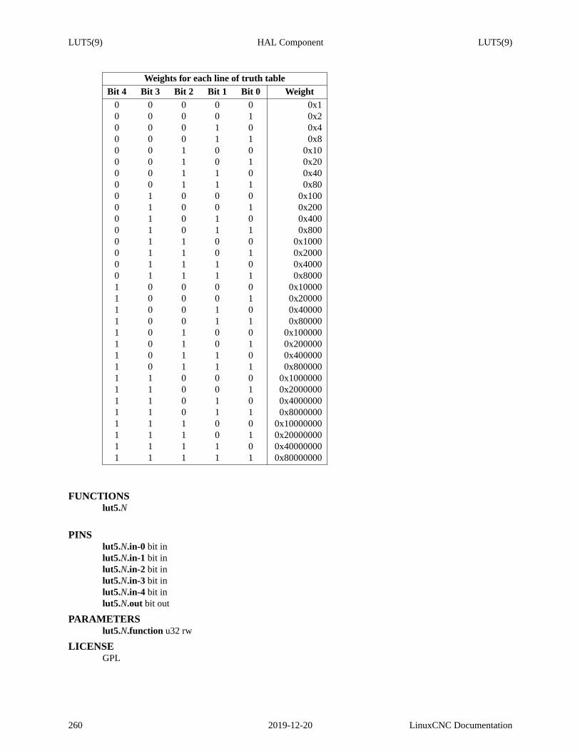
LUT5(9) HAL Component LUT5(9)
Weights for each line of truth tableBit 4 Bit 3 Bit 2 Bit 1 Bit 0 Weight
0 0 0 0 0 0x10 0 0 0 1 0x20 0 0 1 0 0x40 0 0 1 1 0x80 0 1 0 0 0x100 0 1 0 1 0x200 0 1 1 0 0x400 0 1 1 1 0x800 1 0 0 0 0x1000 1 0 0 1 0x2000 1 0 1 0 0x4000 1 0 1 1 0x8000 1 1 0 0 0x10000 1 1 0 1 0x20000 1 1 1 0 0x40000 1 1 1 1 0x80001 0 0 0 0 0x100001 0 0 0 1 0x200001 0 0 1 0 0x400001 0 0 1 1 0x800001 0 1 0 0 0x1000001 0 1 0 1 0x2000001 0 1 1 0 0x4000001 0 1 1 1 0x8000001 1 0 0 0 0x10000001 1 0 0 1 0x20000001 1 0 1 0 0x40000001 1 0 1 1 0x80000001 1 1 0 0 0x100000001 1 1 0 1 0x200000001 1 1 1 0 0x400000001 1 1 1 1 0x80000000
FUNCTIONSlut5.N
PINSlut5.N.in-0 bit inlut5.N.in-1 bit inlut5.N.in-2 bit inlut5.N.in-3 bit inlut5.N.in-4 bit inlut5.N.out bit out
PARAMETERSlut5.N.function u32 rw
LICENSEGPL
260 2019-12-20 LinuxCNC Documentation

MAJ3(9) HAL Component MAJ3(9)
NAMEmaj3 − Compute the majority of 3 inputs
SYNOPSISloadrt maj3 [count=N|names=name1[,name2...]]
FUNCTIONSmaj3.N
PINSmaj3.N.in1 bit inmaj3.N.in2 bit inmaj3.N.in3 bit inmaj3.N.out bit out
PARAMETERSmaj3.N.invert bit rw
LICENSEGPL
LinuxCNC Documentation 2019-12-20 261

MATCH8(9) HAL Component MATCH8(9)
NAMEmatch8 − 8-bit binary match detector
SYNOPSISloadrt match8 [count=N|names=name1[,name2...]]
FUNCTIONSmatch8.N
PINSmatch8.N.in bit in (default:TRUE)
cascade input - if false, output is false regardless of other inputs
match8.N.a0bit inmatch8.N.a1bit inmatch8.N.a2bit inmatch8.N.a3bit inmatch8.N.a4bit inmatch8.N.a5bit inmatch8.N.a6bit inmatch8.N.a7bit inmatch8.N.b0 bit inmatch8.N.b1 bit inmatch8.N.b2 bit inmatch8.N.b3 bit inmatch8.N.b4 bit inmatch8.N.b5 bit inmatch8.N.b6 bit inmatch8.N.b7 bit inmatch8.N.out bit out
true only if in is true and a[m] matches b[m] for m = 0 thru 7
LICENSEGPL
262 2019-12-20 LinuxCNC Documentation

MATRIX_KB(9) HAL Component MATRIX_KB(9)
NAMEmatrix_kb − Convert integers to HAL pins. Optionally scan a matrix of IO ports to create those integers.
SYNOPSISloadrt matrix_kb config=RxCs,RxCs... names=name1,name2...
Creates a component configured for R rows and N columns of matrix keyboard.
If the s option is specified then a set of output rows will be cyclically toggled, and a set of input columnswill be scanned.
Thenamesparameter is optional, but if used then the HAL pins and functions will use the specified namesrather than the default ones. This can be useful for readbility and 2-pass HAL parsing.
There must be no spaces in the parameter lists.
DESCRIPTIONThis component was written to convert matrix keyboard scancodes into HAL pins. However, it might alsofind uses in converting integers from 0 to N into N HAL pins.
The component can work in two ways, and the HAL pins created vary according to mode.
In the default mode the component expects to be given a scan code from a separate driver but could be anyinteger from any source. Most typically this will be the keypad scancode from a Mesa 7i73. The defaultcodes for keyup and keydown are based on the Mesa 7i73 specification with 0x40 indicating a keydown and0x80 a keyup event.If using the 7i73 it is important to match the keypad size jumpers with the HAL component. Valid configsfor the 7i73 are 4x8 and 8x8. Note that the component will only work properly with the version 12 (0xC)7i73 firmware. The firmware version is visible on the component parameters in HAL.
In the optional scan-generation mode thematrix_kb.N.keycodepin changes to an output pin and a set ofoutput row pins and input column pins are created. These need to be connected to physical inputs and out-puts to scan the matrix and return values to HAL. Note thenegative−logic parameter described below, thiswill need to be set on the most common forms of inputs which float high when unconnected.
In both modes a set of HAL output pins are created corresponding to each node of the matrix.
FUNCTIONSmatrix_kb.N
Perform all requested functions. Should be run in a slow thread for effective debouncing.
PINSmatrix_kb.N.col−CC−in bit in
The input pin corresponding to column C.
matrix_kb.N.key.rRcC bit outThe pin corresponding to the key at row R column C of the matrix.
matrix_kb.N.keycodeunsigned in or out depending on mode.This pin should be connected to the scancode generator if hardware such as a 7i73 is being used.In this mode it is an input pin. In the internally-generated scanning mode this pin is an output, butwill not normally be connected.matrix_kb.N.row−RR−out bit out The row scan drivepins.Should be connected to external hardware pins connected to the keypad.
LinuxCNC Documentation 2013-03-24 263

MATRIX_KB(9) HAL Component MATRIX_KB(9)
PARAMETERSmatrix_kb.N.key_rollover unsigned r/w (default 2)
With most matrix keyboards the scancodes are only unambiguous with 1 or 2 keys pressed. Withmore keys pressed phantom keystrokes can appear. Some keyboards are optimised to reduce thisproblem, and some have internal diodes so that any number of keys may be pressed simultane-ously. Increase the value of this parameter if such a keyboard is connected, or if phantom key-strokes are more acceptable than only two keys being active at one time.
matrix_kb.N.negative−logic bit r/w (default 1) only in scan modeWhen no keys are pressed a typical digital input will float high. The input will then be pulled lowby the keypad when the corresponding poll line is low. Set this parameter to 0 if the IO in userequires one row at a time to be high, and a high input corresponds to a button press.
264 2013-03-24 LinuxCNC Documentation

MESSAGE(9) HAL Component MESSAGE(9)
NAMEmessage − Display a message
SYNOPSISloadrt message [count=N|names=name1[,name2...]] [messages=N]
messagesThe messages to display. These should be listed, comma-delimited, inside a single set ofquotes. See the "Description" section for an example. Ifthere are more messages than"count" or "names" then the excess will be ignored. If there are fewer messages than "count"or "names" then an error will be raised and the component will not load.
DESCRIPTIONAllows HAL pins to trigger a message. Example hal commands:loadrt message names=oillow,oilpressure,inverterfail messages="Slideway oil low,No oil pressure,Spindleinverter fault"addf oillow servo-threadaddf oilpressure servo-threadaddf inverterfail servo-thread
setp oillow.edge 0 #this pin should be active lownet no-oil classicladder.0.out-21 oillow.triggernet no-pressure classicladder.0.out-22 oilpressure.triggernet no-inverter classicladder.0.out-23 inverterfail.trigger
When any pin goes active, the corresponding message will be displayed.
FUNCTIONSmessage.N
Display a message
PINSmessage.N.trigger bit in (default:FALSE)
signal that triggers the message
message.N.force bit in (default:FALSE)A FALSE->TRUE transition forces the message to be displayed again if the trigger is active
PARAMETERSmessage.N.edgebit rw (default:TRUE)
Selects the desired edge: TRUE means falling, FALSE means rising
LICENSEGPL v2
LinuxCNC Documentation 2019-12-20 265

MINMAX(9) HAL Component MINMAX(9)
NAMEminmax − Track the minimum and maximum values of the input to the outputs
SYNOPSISloadrt minmax [count=N|names=name1[,name2...]]
FUNCTIONSminmax.N (requires a floating-point thread)
PINSminmax.N.in float inminmax.N.resetbit in
When reset is asserted, ’in’ is copied to the outputs
minmax.N.max float outminmax.N.min float out
LICENSEGPL
266 2019-12-20 LinuxCNC Documentation

MOTION(9) HAL Component MOTION(9)
NAMEmotion − accepts NML motion commands, interacts with HAL in realtime
SYNOPSISloadrt motmod [base_period_nsec=period] [base_thread_fp=0 or 1] [servo_period_nsec=period][traj_period_nsec=period] [num_joints=[0-9] ] ([num_dio=[1-64]] [num_aio=[1-64]])
DESCRIPTIONBy default, the base thread does not support floating point. Software stepping, software encoder counting,and software pwm do not use floating point.base_thread_fpcan be used to enable floating point in thebase thread (for example for brushless DC motor control).
These pins and parameters are created by the realtimemotmod module. This module provides a HAL inter-face for LinuxCNC’s motion planner. Basicallymotmod takes in a list of waypoints and generates a niceblended and constraint-limited stream of joint positions to be fed to the motor drives.
Optionally the number of Digital I/O is set with num_dio. The number of Analog I/O is set with num_aio.The default is 4 each.
Pin names starting with "axis" are actually joint values, but the pins and parameters are still called "axis.N".They are read and updated by the motion-controller function.
PINSaxis.N.amp−enable−outOUT BIT
TRUE if the amplifier for this joint should be enabled
axis.N.amp−fault−in IN BITShould be driven TRUE if an external fault is detected with the amplifier for this joint
axis.N.home−sw−inIN BITShould be driven TRUE if the home switch for this joint is closed
axis.N.homing OUT BITTRUE if the joint is currently homing
axis.N.index−enableIO BITShould be attached to the index−enable pin of the joint’s encoder to enable homing to index pulse
axis.N.is−unlockedIN BITIf the axis is a locked rotary the unlocked sensor should be connected to this pin
axis.N.jog−countsIN S32Connect to the "counts" pin of an external encoder to use a physical jog wheel.
axis.N.jog−enableIN BITWhen TRUE (and in manual mode), any change to "jog−counts" will result in motion. When false,"jog−counts" is ignored.
LinuxCNC Documentation 2007-08-25 267

MOTION(9) HAL Component MOTION(9)
axis.N.jog−scaleIN FLOATSets the distance moved for each count on "jog−counts", in machine units.
axis.N.jog−vel−modeIN BITWhen FALSE (the default), the jogwheel operates in position mode. The axis will move exactlyjog−scale units for each count, regardless of how long that might take. When TRUE, the wheeloperates in velocity mode - motion stops when the wheel stops, even if that means the commandedmotion is not completed.
axis.N.joint−pos−cmdOUT FLOATThe joint (as opposed to motor) commanded position. There may be several offsets between thejoint and motor coordinates: backlash compensation, screw error compensation, and home offsets.
axis.N.joint−pos−fb OUT FLOATThe joint feedback position. This value is computed from the actual motor position minus jointoffsets. Useful for machine visualization.
axis.N.motor−pos−cmdOUT FLOATThe commanded position for this joint.
axis.N.motor−pos−fb IN FLOATThe actual position for this joint.
axis.N.neg−lim−sw−inIN BITShould be driven TRUE if the negative limit switch for this joint is tripped.
axis.N.pos−lim−sw−inIN BITShould be driven TRUE if the positive limit switch for this joint is tripped.
axis.N.unlock OUT BITTRUE if the axis is a locked rotary and a move is commanded.
motion.adaptive−feedIN FLOATWhen adaptive feed is enabled with M52 P1, the commanded velocity is multiplied by this value.This effect is multiplicative with the NML-level feed override value and motion.feed−hold.
motion.analog−in−NN IN FLOATThese pins are used by M66 Enn wait-for-input mode.
motion.analog−out−NN OUT FLOATThese pins are used by M67-68.
motion.coord−error OUT BITTRUE when motion has encountered an error, such as exceeding a soft limit
motion.coord−modeOUT BITTRUE when motion is in "coordinated mode", as opposed to "teleop mode"
268 2007-08-25 LinuxCNC Documentation
MOTION(9) HAL Component MOTION(9)
motion.current−vel OUT FLOATCurrent cartesian velocity
motion.digital−in−NN IN BITThese pins are used by M66 Pnn wait-for-input mode.
motion.digital−out−NN OUT BITThese pins are controlled by the M62 through M65 words.
motion.distance−to−goOUT FLOATDistance remaining in the current move
motion.enableIN BITIf this bit is driven FALSE, motion stops, the machine is placed in the "machine off" state, and amessage is displayed for the operator. For normal motion, drive this bit TRUE.
motion.feed−holdIN BITWhen Feed Stop Control is enabled with M53 P1, and this bit is TRUE, the feed rate is set to 0.
motion.feed−inhibit IN BITWhen this pin is TRUE, machine motion is inhibited (this includes jogs, programmed feeds, andprogrammed rapids, aka traverse moves).
If the machine is performing a spindle synchronized move when this pin goes TRUE, the spindlesynchronized motion will finish, and any following moves will be inhibited (this is to prevent dam-age to the machine, the tool, or the work piece).
If the machine is in the middle of a (non-spindle synchronized) move when this pin goes TRUE,the machine will decelerate to a stop at the maximum allowed acceleration rate.
Motion resumes when this pin goes FALSE.
motion.in−position OUT BITTRUE if the machine is in position (ie, not currently moving towards the commanded position).
motion.probe−input IN BITG38.n uses the value on this pin to determine when the probe has made contact. TRUE for probecontact closed (touching), FALSE for probe contact open.
motion.program−line OUT S32The current program line while executing. Zero if not running or between lines while single step-ping.
motion.requested−velOUT FLOATThe current requested velocity in user units per second. This value is the F-word setting from theG-code file, possibly reduced to accomodate machine velocity and acceleration limits. The valueon this pin does not reflect the feed override or any other adjustments.
LinuxCNC Documentation 2007-08-25 269

MOTION(9) HAL Component MOTION(9)
motion.spindle−at−speedIN BITMotion will pause until this pin is TRUE, under the following conditions: before the first feedmove after each spindle start or speed change; before the start of every chain of spindle-synchro-nized moves; and if in CSS mode, at every rapid->feed transition.
motion.spindle−brakeOUT BITTRUE when the spindle brake should be applied
motion.spindle−forward OUT BITTRUE when the spindle should rotate forward
motion.spindle−index−enableI/O BITFor correct operation of spindle synchronized moves, this signal must be hooked to theindex−enable pin of the spindle encoder.
motion.spindle−inhibit IN BITWhen TRUE, the spindle speed is set and held to 0.
motion.spindle−onOUT BITTRUE when spindle should rotate
motion.spindle−rev erseOUT BITTRUE when the spindle should rotate backward
motion.spindle−revs IN FLOATFor correct operation of spindle synchronized moves, this signal must be hooked to the positionpin of the spindle encoder.
motion.spindle−speed−inIN FLOATActual spindle speed feedback in revolutions per second; used for G96 (constant surface speed)and G95 (feed per revolution) modes.
motion.spindle−speed−outOUT FLOATDesired spindle speed in rotations per minute
motion.spindle−speed−out−absOUT FLOATDesired spindle speed in rotations per minute, always positive reg ardless of spindle direction.
motion.spindle−speed−out−rpsOUT floatDesired spindle speed in rotations per second
motion.spindle−speed−out−rps−absOUT floatDesired spindle speed in rotations per second, always positive reg ardless of spindle direction.
motion.spindle−orient−angleOUT FLOATDesired spindle orientation for M19. Value of the M19 R word parameter plus the value of the[RS274NGC]ORIENT_OFFSET ini parameter.
270 2007-08-25 LinuxCNC Documentation

MOTION(9) HAL Component MOTION(9)
motion.spindle−orient−modeOUT BITDesired spindle rotation mode. Reflects M19 P parameter word.
motion.spindle−orient OUT BITIndicates start of spindle orient cycle. Set by M19. Cleared by any of M3,M4,M5. If spindle−ori-ent−fault is not zero during spindle−orient true, the M19 command fails with an error message.
motion.spindle−is−orientedIN BITAcknowledge pin for spindle−orient. Completes orient cycle. If spindle−orient was true whenspindle−is−oriented was asserted, the spindle−orient pin is cleared and the spindle−locked pin isasserted. Also, the spindle−brake pin is asserted.
motion.spindle−orient−fault IN S32Fault code input for orient cycle. Any value other than zero will cause the orient cycle to abort.
motion.spindle−lockedOUT BITSpindle orient complete pin. Cleared by any of M3,M4,M5.
motion.teleop−modeOUT bit
motion.tooloffset.xOUT FLOAT
motion.tooloffset.yOUT FLOAT
motion.tooloffset.zOUT FLOAT
motion.tooloffset.aOUT FLOAT
motion.tooloffset.bOUT FLOAT
motion.tooloffset.cOUT FLOAT
motion.tooloffset.uOUT FLOAT
motion.tooloffset.vOUT FLOAT
motion.tooloffset.wOUT FLOATCurrent tool offset in all 9 axes.
DEBUGGING PINSMany of the pins below serve as debugging aids, and are subject to change or removal at any time.
axis.N.activeOUT BITTRUE when this joint is active
axis.N.backlash−corr OUT FLOATBacklash or screw compensation raw value
LinuxCNC Documentation 2007-08-25 271

MOTION(9) HAL Component MOTION(9)
axis.N.backlash−filt OUT FLOATBacklash or screw compensation filtered value (respecting motion limits)
axis.N.backlash−velOUT FLOATBacklash or screw compensation velocity
axis.N.coarse−pos−cmdOUT FLOAT
axis.N.error OUT BITTRUE when this joint has encountered an error, such as a limit switch closing
axis.N.f−error OUT FLOATThe actual following error
axis.N.f−error−lim OUT FLOATThe following error limit
axis.N.f−errored OUT BITTRUE when this joint has exceeded the following error limit
axis.N.faulted OUT BIT
axis.N.free−pos−cmdOUT FLOATThe "free planner" commanded position for this joint.
axis.N.free−tp−enableOUT BITTRUE when the "free planner" is enabled for this joint
axis.N.free−vel−lim OUT FLOATThe velocity limit for the free planner
axis.N.homedOUT BITTRUE if the joint has been homed
axis.N.in−position OUT BITTRUE if the joint is using the "free planner" and has come to a stop
axis.N.joint−vel−cmd OUT FLOATThe joint’s commanded velocity
axis.N.kb−jog−activeOUT BIT
axis.N.neg−hard−limit OUT BITThe negative hard limit for the joint
272 2007-08-25 LinuxCNC Documentation

MOTION(9) HAL Component MOTION(9)
axis.N.pos−hard−limit OUT BITThe positive hard limit for the joint
axis.N.wheel−jog−activeOUT BIT
motion.motion−enabledOUT BIT
motion.motion−type OUT S32These values are from src/emc/nml_intf/motion_types.h
0: Idle (no motion)
1: Traverse
2: Linear feed
3: Arc feed
4: Tool change
5: Probing
6: Rotary axis indexing
motion.on−soft−limit OUT BIT
motion.program−line OUT S32
motion.teleop−modeOUT BITTRUE when motion is in "teleop mode", as opposed to "coordinated mode"
PARAMETERSMany of the parameters serve as debugging aids, and are subject to change or removal at any time.
motion−command−handler.time
motion−command−handler.tmax
motion−controller.time
motion−controller.tmaxShow information about the execution time of these HAL functions in CPU cycles
motion.debug−*These values are used for debugging purposes.
motion.servo.last−periodThe number of CPU cycles between invocations of the servo thread. Typically, this numberdivided by the CPU speed gives the time in seconds, and can be used to determine whether therealtime motion controller is meeting its timing constraints
LinuxCNC Documentation 2007-08-25 273

MOTION(9) HAL Component MOTION(9)
FUNCTIONSGenerally, these functions are both added to the servo-thread in the order shown.
motion−command−handlerProcesses motion commands coming from user space
motion−controllerRuns the LinuxCNC motion controller
BUGSThis manual page is horribly incomplete.
SEE ALSOiocontrol(1)
274 2007-08-25 LinuxCNC Documentation

MOVEOFF(9) HAL Component MOVEOFF(9)
NAMEmoveoff − Component for Hal-only offsets
SYNOPSISloadrt moveoff [count=N|names=name1[,name2...]] [personality=P,P,...]
DESCRIPTIONThe moveoff component is used to offset joint positions using custom Hal connections. Implementing anoffset-while-program-is-paused functionality is supported with appropriate connections for the input pins.Nine joints are supported.
The axis offset pin values (offset-in-M) are continuously applied (respecting limits on value, velocity, andacceleration) to the output pins (offset-current-M, pos-plusoffset-M, fb-minusoffset-M) when both enablinginput pins (apply-offsets and move-enable) are TRUE. Thetwo enabling inputs are anded internally. Awarning pin is set and a message issued if the apply-offsets pin is deasserted while offsets are applied. Thewarning pin remains TRUE until the offsets are removed or the apply-offsets pin is set.
Typically, the move-enable pin is connected to external controls and the apply-offsets pin is connected tohalui.program.is-paused (for offsets only while paused) or set to TRUE (for continuously applied offsets).
Applied offsets areautomatically returned to zero (respecting limits) when either of the enabling inputs isdeactivated. Thezero value tolerance is specified by the epsilon input pin value.
Waypoints are recorded when the moveoff componenent is enabled.Waypoints are managed with the way-point-sample-secs and waypoint-threshold pins. When the backtrack-enable pin is TRUE, the auto-returnpath follows the recorded waypoints. Whenthe memory available for waypoints is exhausted, offsets arefrozen and the waypoint-limit pin is asserted. This restriction applies regardless of the state of the back-track-enable pin. An enabling pin must be deasserted to allow a return to the original (non-offset position).
Backtracking through waypoints results inslowermovement rates as the moves are point-to-point respect-ing velocity and acceleration settings. The velocity and acceleration limit pins can be managed dynami-cally to control offsets at all times.
When backtrack-enable is FALSE, the auto-return move is NOT coordinated, each axis returns to zero at itsown rate. Ifa controlled path is wanted in this condition, each axis should be manually returned to zerobefore deasserting an enabling pin.
The waypoint-sample-secs, waypoint-threshold, and epsilon pins are evaluated only when the component isidle.
The offsets-applied output pin is provided to indicate the current state to a GUI so that program resumptioncan be managed. If the offset(s) are non-zero when the apply-offsets pin is deasserted (for example whenresuming a program when offsetting during a pause), offsets are returned to zero (respecting limits) and anError message is issued.
Caution: If offsets are enabled and applied and the machine is turned off for any reason, anyexternal Hallogic that manages the enabling pins and the offset-in-M inputs is responsible for their state when themachine is subsequently turned on again.
This Hal-only means of offsetting is typically not known to LinuxCNC nor available in GUI preview dis-plays. No protection is provided for offset moves that exceed soft limits managed by LinuxCNC. Sincesoft limits are not honored, an offset move may encounter hard limits (orCRASH if there are no limitswitches). Useof the offset-min-M and offset-max-M inputs to limit travel is recommended. Triggering ahard limit will turn off the machine -- seeCaution above.
The offset-in-M values may be set with inifile settings, controlled by a GUI, or managed by other Hal
LinuxCNC Documentation 2019-12-20 275
MOVEOFF(9) HAL Component MOVEOFF(9)
components and connections. Fixed values may be appropriate in simple cases where the direction andamount of offset is well-defined but a control method is required to deactivate an enabling pin in order toreturn offsets to zero. GUIs may provide means for users to set, increment, decrement, and accumulate off-set values for each axis and may set offset-in-M values to zero before deasserting an enabling pin.
The default values for accel, vel, min, max, epsilon, waypoint-sample-secs, and waypoint-threshold maynot be suitable for any particular application. This Hal component is unaware of limits enforced elsewhereby LinuxCNC. Users should test usage in a simulator application and understand all hazardsbeforeuse onhardware.
The module personality item sets the number of joints supported (default==3, maximum is 9).
Use of the names= option for naming isrequired for compatibility with the gui provided as scripts/move-off_gui:loadrt moveoff names=mv personality=number_of_joints
man moveoff_gui for more information
EXAMPLESExample simulator configs that demonstrate the moveoff component and a simple gui (scripts/moveoff_gui)are located in configs/sim/axis/moveoff. The axis gui is used for the demonstrations and the configs can beadapted for other guis like touchy and gscreen. An example with the touchy gui is provided in con-figs/sim/touchy/ngcgui/.
FUNCTIONSmoveoff.N.read-inputs (requires a floating-point thread)
Read all inputs
moveoff.N.write-outputs (requires a floating-point thread)Write computed offset outputs (offset-current-M, pos-plusoffset-M, fb-minusoffset-M). All otheroutputs are updated by read-inputs()
PINSmoveoff.N.power-onbit in
Connect to motion.motion-enabled
moveoff.N.move-enablebit inEnable offsets (Enabling requires apply-offset TRUE also)
moveoff.N.apply-offsetsbit inEnable offsets (Enabling requires move-enable TRUE also)
moveoff.N.backtrack-enablebit in (default:1)Enable backtrack on auto-return
moveoff.N.epsilonfloat in (default:0.0005)When enabling pins are deactivated, return to un-offsetted position within epsilon units.Warning:values that are too small in value may cause overshoot, Aminimum value of 0.0001 issilentlyenforced
moveoff.N.waypoint-threshold float in (default:0.02)Minimum distance (in a single axis) for a new waypoint
moveoff.N.waypoint-sample-secsfloat in (default:0.02)Minimum sample interval (in seconds) for a new waypoint
276 2019-12-20 LinuxCNC Documentation

MOVEOFF(9) HAL Component MOVEOFF(9)
moveoff.N.warning bit outSet TRUE if apply-offsets is deasserted while offset-applied is TRUE
moveoff.N.offset-appliedbit outTRUE if one or more offsets are applied
moveoff.N.waypoint-limit bit out (default:0)Indicates waypoint limit reached (motion ceases), an enabling pin must be deasserted to initiatereturn to original position
moveoff.N.waypoint-ct s32 outWaypoint count (for debugging)
moveoff.N.waypoint-percent-useds32 outPercent of available waypoints used
moveoff.N.offset-in-M float in (M=0..personality)Joint offset input value
moveoff.N.pos-M float in (M=0..personality)Joint position (typ: axis.0.motor-pos-cmd)
moveoff.N.fb-M float in (M=0..personality)Joint feedback (typ from encoder and input to pid controller (pid.feedback))
moveoff.N.offset-current-M float out (M=0..personality)Joint offset current value
moveoff.N.pos-plusoffset-M float out (M=0..personality)Computed joint position plus offset (typically connect to pid command input)
moveoff.N.fb-minusoffset-M float out (M=0..personality)Computed Joint feedback minus offset (typically connected to axis.0.motor-pos-fb
moveoff.N.offset-vel-M float in (M=0..personality) (default:10)Joint offset velocity limit
moveoff.N.offset-accel-M float in (M=0..personality) (default:100)Joint offset acceleration limit
moveoff.N.offset-min-M float in (M=0..personality) (default:-1e20)Minimum limit for applied joint offset (typ negative)
moveoff.N.offset-max-M float in (M=0..personality) (default:1e20)Maximum limit for applied offset (typ positive)
moveoff.N.dbg-waypoint-limit-test bit inDebug input to test with limited number of waypoints
moveoff.N.dbg-states32 outDebug output for current state of state machine
LICENSEGPL
LinuxCNC Documentation 2019-12-20 277

MULT2(9) HAL Component MULT2(9)
NAMEmult2 − Product of two inputs
SYNOPSISloadrt mult2 [count=N|names=name1[,name2...]]
FUNCTIONSmult2.N (requires a floating-point thread)
PINSmult2.N.in0 float inmult2.N.in1 float inmult2.N.out float out
out = in0 * in1
LICENSEGPL
278 2019-12-20 LinuxCNC Documentation

MULTICLICK(9) HAL Component MULTICLICK(9)
NAMEmulticlick − Single-, double-, triple-, and quadruple-click detector
SYNOPSISloadrt multiclick [count= N|names=name1[,name2...]]
DESCRIPTIONA click is defined as a rising edge on the ’in’ pin, followed by the ’in’ pin being True for at most ’max-hold-ns’ nanoseconds, followed by a falling edge.
A double-click is defined as two clicks, separated by at most ’max-space-ns’ nanoseconds with the ’in’ pinin the False state.
I bet you can guess the definition of triple- and quadruple-click.
You probably want to run the input signal through a debounce component before feeding it to the multiclickdetector, if the input is at all noisy.
The ’*-click’ pins go high as soon as the input detects the correct number of clicks.
The ’*-click-only’ pins go high a short while after the click, after the click separator space timeout hasexpired to show that no further click is coming. This is useful for triggering halui MDI commands.
FUNCTIONSmulticlick. N
Detect single-, double-, triple-, and quadruple-clicks
PINSmulticlick. N.in bit in
The input line, this is where we look for clicks.
multiclick. N.single-clickbit outGoes high briefly when a single-click is detected on the ’in’ pin.
multiclick. N.single-click-onlybit outGoes high briefly when a single-click is detected on the ’in’ pin and no second click followed it.
multiclick. N.double-click bit outGoes high briefly when a double-click is detected on the ’in’ pin.
multiclick. N.double-click-only bit outGoes high briefly when a double-click is detected on the ’in’ pin and no third click followed it.
multiclick. N.triple-click bit outGoes high briefly when a triple-click is detected on the ’in’ pin.
multiclick. N.triple-click-only bit outGoes high briefly when a triple-click is detected on the ’in’ pin and no fourth click followed it.
multiclick. N.quadruple-click bit outGoes high briefly when a quadruple-click is detected on the ’in’ pin.
multiclick. N.quadruple-click-only bit outGoes high briefly when a quadruple-click is detected on the ’in’ pin and no fifth click followed it.
multiclick. N.states32 out
PARAMETERSmulticlick. N.invert-input bit rw (default:FALSE)
If FALSE (the default), clicks start with rising edges. If TRUE, clicks start with falling edges.
LinuxCNC Documentation 2019-12-20 279

MULTICLICK(9) HAL Component MULTICLICK(9)
multiclick. N.max-hold-nsu32 rw (default:250000000)If the input is held down longer than this, it’s not part of a multi-click. (Default 250,000,000 ns,250 ms.)
multiclick. N.max-space-nsu32 rw (default:250000000)If the input is released longer than this, it’s not part of a multi-click. (Default 250,000,000 ns, 250ms.)
multiclick. N.output-hold-ns u32 rw (default:100000000)Positive pulses on the output pins last this long. (Default 100,000,000 ns, 100 ms.)
LICENSEGPL
280 2019-12-20 LinuxCNC Documentation

MULTISWITCH(9) HAL Component MULTISWITCH(9)
NAMEmultiswitch − This component toggles between a specified number of output bits
SYNOPSISloadrt multiswitch personality=P [cfg=N]
cfg cfg should be a comma-separated list of sizes for example cfg=2,4,6 would create 3 instancesof 2, 4 and 6 bits respectively.Ignore the "personality" parameter, that is auto-generated
FUNCTIONSmultiswitch.N (requires a floating-point thread)
PINSmultiswitch.N.up bit in (default:false)
Receives signal to toggle up
multiswitch.N.down bit in (default:false)Receives signal to toggle down
multiswitch.N.bit-MM bit out (MM=00..personality) (default:false)Output bits
PARAMETERSmultiswitch.N.top-position u32 rw
Number of positions
multiswitch.N.position s32 rwCurrent state (may be set in the HAL)
AUTHORArcEye [email protected] / Andy Pugh [email protected]
LICENSEGPL
LinuxCNC Documentation 2019-12-20 281

MUX16(9) HAL Component MUX16(9)
NAMEmux16 − Select from one of sixteen input values
SYNOPSISloadrt mux16 [count=N|names=name1[,name2...]]
FUNCTIONSmux16.N (requires a floating-point thread)
PINSmux16.N.use-graycodebit in
This signifies the input will use Gray code instead of binary. Gray code is a good choice whenusing physical switches because for each increment only one select input changes at a time.
mux16.N.suppress-no-inputbit inThis suppresses changing the output if all select lines are false. Thisstops unwanted jumps in out-put between transitions of input.but make in00 unavaliable.
mux16.N.debounce-timefloat insets debouce time in seconds.eg. .10 = a tenth of a second input must be stable this long beforeoutputs changes. This helps to ignore ’noisy’ switches.
mux16.N.selM bit in (M=0..3)Together, these determine whichinN value is copied toout.
mux16.N.out-f float outmux16.N.out-ss32 out
Follows the value of one of theinN values according to the fourselvalues and whether use-gray-code is active. The s32 value will be trunuated and limited to the max and min values of signedvalues.
sel3=FALSE, sel2=FALSE, sel1=FALSE, sel0=FALSEout follows in0
sel3=FALSE, sel2=FALSE, sel1=FALSE, sel0=TRUEout follows in1
etc.
mux16.N.inMM float in (MM=00..15)array of selectable outputs
PARAMETERSmux16.N.elapsedfloat r
Current value of the internal debounce timerfor debugging.
mux16.N.selecteds32 rCurrent value of the internal selection variable after conversionfor debugging
LICENSEGPL
282 2019-12-20 LinuxCNC Documentation

MUX2(9) HAL Component MUX2(9)
NAMEmux2 − Select from one of two input values
SYNOPSISloadrt mux2 [count=N|names=name1[,name2...]]
FUNCTIONSmux2.N (requires a floating-point thread)
PINSmux2.N.selbit inmux2.N.out float out
Follows the value of in0 if sel is FALSE, or in1 if sel is TRUE
mux2.N.in1 float inmux2.N.in0 float in
LICENSEGPL
LinuxCNC Documentation 2019-12-20 283

MUX4(9) HAL Component MUX4(9)
NAMEmux4 − Select from one of four input values
SYNOPSISloadrt mux4 [count=N|names=name1[,name2...]]
FUNCTIONSmux4.N (requires a floating-point thread)
PINSmux4.N.sel0bit inmux4.N.sel1bit in
Together, these determine whichinN value is copied toout.
mux4.N.out float outFollows the value of one of theinN values according to the twoselvalues
sel1=FALSE, sel0=FALSEout follows in0
sel1=FALSE, sel0=TRUEout follows in1
sel1=TRUE, sel0=FALSEout follows in2
sel1=TRUE, sel0=TRUEout follows in3
mux4.N.in0 float inmux4.N.in1 float inmux4.N.in2 float inmux4.N.in3 float in
LICENSEGPL
284 2019-12-20 LinuxCNC Documentation

MUX8(9) HAL Component MUX8(9)
NAMEmux8 − Select from one of eight input values
SYNOPSISloadrt mux8 [count=N|names=name1[,name2...]]
FUNCTIONSmux8.N (requires a floating-point thread)
PINSmux8.N.sel0bit inmux8.N.sel1bit inmux8.N.sel2bit in
Together, these determine whichinN value is copied toout.
mux8.N.out float outFollows the value of one of theinN values according to the threeselvalues
sel2=FALSE, sel1=FALSE, sel0=FALSEout follows in0
sel2=FALSE, sel1=FALSE, sel0=TRUEout follows in1
sel2=FALSE, sel1=TRUE, sel0=FALSEout follows in2
sel2=FALSE, sel1=TRUE, sel0=TRUEout follows in3
sel2=TRUE, sel1=FALSE, sel0=FALSEout follows in4
sel2=TRUE, sel1=FALSE, sel0=TRUEout follows in5
sel2=TRUE, sel1=TRUE, sel0=FALSEout follows in6
sel2=TRUE, sel1=TRUE, sel0=TRUEout follows in7
mux8.N.in0 float inmux8.N.in1 float inmux8.N.in2 float inmux8.N.in3 float inmux8.N.in4 float inmux8.N.in5 float inmux8.N.in6 float inmux8.N.in7 float in
LICENSEGPL
LinuxCNC Documentation 2019-12-20 285
MUX_GENERIC(9) HAL Component MUX_GENERIC(9)
NAMEmux_generic − choose one from several input values
SYNOPSISloadrt mux_generic config="bb8,fu12...."
FUNCTIONSmux−gen.NN Depending on the data types can run in either a floating
point or non-floating point thread.
PINSmux−gen.NN.suppress−no−inputbit in
This suppresses changing the output if all select lines are false. Thisstops unwanted jumps in out-put between transitions of input.but makes in00 unavaliable.
mux−gen.NN.debounce−usunsigned insets debouce time in microseconds.eg. 100000 = a tenth of a second. The selection inputs mustbe stable this long before the output changes. This helps to ignore ’noisy’ switches.
mux−gen.NN.sel−bitMM bit in (M=0..N)
mux−gen.NN.sel−int unsigned inTogether, these determine whichinN value is copied tooutput. The bit pins are interpreted asbinary bits, and the result is simply added on to the integer pin input. It is expected that either oneor the other would normally be used. Hower, the possibility exists to use a higher-order bit to"shift" the values set by the integer pin. The sel−bit pins are only created when the size of themux_gen component is an integer power of two. Thiscomponent (unlike mux16) does not offerthe option of decoding gray-code, however the same effect can be achieved by arranging the orderof the input values to suit.
mux−gen.NN.out−[bit/float/s32/u32]variable-type outFollows the value of one of theinN values according to the selection bits and/or the selection num-ber. Values will be converted/truncated according to standard C rules. This means, for examplethat a float input greater than 2147483647 will give an S32 output of −2147483648.
mux−gen.NN.in−[bit/float/s32/u32]−MM variable-type inThe possible output values that are selected by the selection pins.
PARAMETERSmux−gen.N.elapsedfloat r
Current value of the internal debounce timer for debugging.
mux−gen.N.selecteds32 rCurrent value of the internal selection variable after conversion for debugging. Possibly useful forsetting up gray-code switches.
DESCRIPTIONThis component is a more general version of the other multiplexing components. It allows the creation ofarbitrary-size multiplexers (up to 1024 entries) and also supports differing data types on the input and out-put pins. The configuration string is a comma-separated list of code-letters and numbers, such as"bb4,fu12" This would create a 4-element bit-to-bit mux and a 12-element float-to-unsigned mux. The codeletters are b = bit, f = float, s = signed integer, u = unsigned integer. The first letter code is the input type,the second is the output type. The codes are not case-sensitive. The order of the letters is significant but theposition in the string is not. Do not insert any spaces in the config string. Any non-zero float value will be
286 2013-05-27 LinuxCNC Documentation

MUX_GENERIC(9) HAL Component MUX_GENERIC(9)
converted to a "true" output in bit form. Be wary that float datatypes can be very, very, close to zero and notactually be equal to zero.
Each mux has its own HAL function and must be added to a thread separately. If neither input nor output isof type float then the function is base-thread (non floating-point) safe. Any mux_generic with a floatingpoint input or output can only be added to a floating-point thread.
LICENSEGPL
AUTHORAndy Pugh
LinuxCNC Documentation 2013-05-27 287

NEAR(9) HAL Component NEAR(9)
NAMEnear − Determine whether two values are roughly equal.
SYNOPSISloadrt near [count=N|names=name1[,name2...]]
FUNCTIONSnear.N (requires a floating-point thread)
PINSnear.N.in1 float innear.N.in2 float innear.N.out bit out
out is true if in1 andin2 are within a factor ofscale(i.e., for in1 positive, in1/scale <= in2 <=in1*scale), OR if their absolute difference is no greater thandifference (i.e., |in1-in2| <= differ-ence).out is false otherwise.
PARAMETERSnear.N.scalefloat rw (default:1)near.N.differencefloat rw (default:0)
LICENSEGPL
288 2019-12-20 LinuxCNC Documentation

NOT(9) HAL Component NOT(9)
NAMEnot − Inverter
SYNOPSISloadrt not [count=N|names=name1[,name2...]]
FUNCTIONSnot.N
PINSnot.N.in bit innot.N.out bit out
LICENSEGPL
LinuxCNC Documentation 2019-12-20 289

OFFSET(9) HAL Component OFFSET(9)
NAMEoffset − Adds an offset to an input, and subtracts it from the feedback value
SYNOPSISloadrt offset [count=N|names=name1[,name2...]]
FUNCTIONSoffset.N.update-output (requires a floating-point thread)
Updated the output value by adding the offset to the input
offset.N.update-feedback(requires a floating-point thread)Update the feedback value by subtracting the offset from the feedback
PINSoffset.N.offsetfloat in
The offset value
offset.N.in float inThe input value
offset.N.out float outThe output value
offset.N.fb-in float inThe feedback input value
offset.N.fb-out float outThe feedback output value
LICENSEGPL
290 2019-12-20 LinuxCNC Documentation

ONESHOT(9) HAL Component ONESHOT(9)
NAMEoneshot − one-shot pulse generator
SYNOPSISloadrt oneshot [count=N|names=name1[,name2...]]
DESCRIPTIONcreates a variable-length output pulse when the input changes state. This function needs to run in a threadwhich supports floating point (typically the servo thread). This means that the pulse length has to be a mul-tiple of that thread period, typically 1mS.For a similar function that can run in the base thread, and whichoffers higher resolution, see "edge".
FUNCTIONSoneshot.N (requires a floating-point thread)
Produce output pulses from input edges
PINSoneshot.N.in bit in
Trigger input
oneshot.N.out bit outActive high pulse
oneshot.N.out-not bit outActive low pulse
oneshot.N.width float in (default:0)Pulse width in seconds
oneshot.N.time-left float outTime left in current output pulse
PARAMETERSoneshot.N.retriggerable bit rw (default:TRUE)
Allow additional edges to extend pulse
oneshot.N.rising bit rw (default:TRUE)Trigger on rising edge
oneshot.N.falling bit rw (default:FALSE)Trigger on falling edge
LICENSEGPL
LinuxCNC Documentation 2019-12-20 291

OPTO_AC5(9) HAL Component OPTO_AC5(9)
NAMEopto_ac5 − Realtime driver for opto22 PCI-AC5 cards
SYNOPSISloadrt opto_ac5 [portconfig0=0xN] [portconfig1=0xN]
DESCRIPTIONThese pins and parameters are created by the realtimeopto_ac5module. Theportconfig0 and portconfig1variables are used to configure the two ports of each card. The first 24 bits of a 32 bit number represent the24 i/o points of each port. The lowest (rightmost) bit would be HAL pin 0 which is header connector pin47. Then next bit to the left would be HAL pin 1, header connector pin 45 and so on, untill bit 24 would beHAL pin 23 , header connector pin 1. "1" bits represent output points. So channel 0..11 as inputs and12..23 as outputs would be represented by (in binary) 111111111111000000000000 which is 0xfff000 inhexadecimal. Thatis the number you would use Eg. loadrt opto_ac5 portconfig0=0xfff000
If no portconfig variable is specified the default configuration is 12 inputs then 12 outputs.
Up to 4 boards are supported. Boards are numbered starting at 0.
Portnumber can be 0 or 1. Port 0 is closes to the card bracket.
PINSopto_ac5.[BOARDNUMBER].port[ PORTNUMBER].in−[PINNUMBER] OUT bitopto_ac5.[BOARDNUMBER].port[ PORTNUMBER].in−[PINNUMBER]−not OUT bit
Connect a hal bit signal to this pin to read an i/o point from the card. The PINNUMBER repre-sents the position in the relay rack. Eg. PINNUMBER 0 is position 0 in a opto22 relay rack andwould be pin 47 on the 50 pin header connector. The−not pin is inverted so that LOW giv esTRUE and HIGH gives FALSE.
opto_ac5.[BOARDNUMBER].port[ PORTNUMBER].out−[PINNUMBER] IN bitConnect a hal bit signal to this pin to write to an i/o point of the card. The PINNUMBER repre-sents the position in the relay rack.Eg. PINNUMBER 23 is position 23 in a opto22 relay rack andwould be pin 1 on the 50 pin header connector.
opto_ac5.[BOARDNUMBER].led[NUMBER] OUT bitTurns one of the on board LEDS on/off. LEDS are numbered 0 to 3.
PARAMETERSopto_ac5.[BOARDNUMBER].port[ PORTNUMBER].out−[PINNUMBER]−invert W bit
When TRUE, invert the meaning of the corresponding−out pin so that TRUE gives LOW andFALSE gives HIGH.
FUNCTIONSopto_ac5.0.digital−read
Add this to a thread to read all the input points.
opto_ac5.0.digital−writeAdd this to a thread to write all the output points and LEDS.
BUGSAll boards are loaded with the same port configurations as the first board.
292 2008-08-04 LinuxCNC Documentation

OPTO_AC5(9) HAL Component OPTO_AC5(9)
SEE ALSOhttp://wiki.linuxcnc.org/cgi−bin/wiki.pl?OptoPciAc5
LinuxCNC Documentation 2008-08-04 293

OR2(9) HAL Component OR2(9)
NAMEor2 − Two-input OR gate
SYNOPSISloadrt or2 [count=N|names=name1[,name2...]]
FUNCTIONSor2.N
PINSor2.N.in0 bit inor2.N.in1 bit inor2.N.out bit out
out is computed from the value ofin0 andin1 according to the following rule:
in0=FALSE in1=FALSEout=FALSE
Otherwise,out=TRUE
LICENSEGPL
294 2019-12-20 LinuxCNC Documentation

ORIENT(9) HAL Component ORIENT(9)
NAMEorient − Provide a PID command input for orientation mode based on current spindle position, target angleand orient mode
SYNOPSISloadrt orient [count=N|names=name1[,name2...]]
DESCRIPTIONThis component is designed to support a spindle orientation PID loop by providing a command value, andfit with the motion spindle-orient support pins to support the M19 code.
The spindle is assumed to have stopped in an arbitrary position. The spindle encoder position is linked tothe position pin. The currentvalue of the position pin is sampled on a positive edge on theenablepin,andcommand is computed and set as follows: floor(number of full spindle revolutions in theposition sam-pled on positive edge) plusangle/360 (the fractional revolution) +1/-1/0 depending onmode.
Themodepin is interpreted as follows:
0: the spindle rotates in the direction with the lesser angle, which may be clockwise or counterclockwise.
1: the spindle rotates always rotates clockwise to the new angle.
2: the spindle rotates always rotates counterclockwise to the new angle.
HAL USAGEOnmotion.spindle-orient disconnect the spindle control and connect to the orient-pid loop:
loadrt orient names=orientloadrt pid names=orient-pidnet orient-angle motion.spindle-orient-angle orient.anglenet orient-mode motion.spindle-orient-mode orient.modenet orient-enable motion.spindle-orient orient.enable orient-pid.enablenet spindle-pos encoder.position orient.position orient-pid.feedbacknet orient-command orient.command orient-pid.command
FUNCTIONSorient.N (requires a floating-point thread)
Updatecommandbased onenable, position, modeandangle.
PINSorient.N.enablebit in
enable angular output for orientation mode
orient.N.modes32 in0: rotate - shortest move; 1: always rotate clockwise; 2: always rotate counterclockwise
orient.N.position float inspindle position input, unit 1 rev
orient.N.anglefloat inorient target position in degrees, 0 <= angle < 360
orient.N.commandfloat outtarget spindle position, input to PID command
LinuxCNC Documentation 2019-12-20 295

ORIENT(9) HAL Component ORIENT(9)
orient.N.poserr float outin degrees - aid for PID tuning
AUTHORMichael Haberler
LICENSEGPL
296 2019-12-20 LinuxCNC Documentation

PID(9) HAL Component PID(9)
NAMEpid − proportional/integral/derivative controller
SYNOPSISloadrt pid [num_chan=num| names=name1[,name2...]] [debug=dbg]
DESCRIPTIONpid is a classic Proportional/Integral/Derivative controller, used to control position or speed feedback loopsfor servo motors and other closed-loop applications.
pid supports a maximum of sixteen controllers. The number that are actually loaded is set by thenum_chanargument when the module is loaded. Alternatively, specify names= and unique names sepa-rated by commas.
Thenum_chan=andnames=specifiers are mutually exclusive. If neithernum_chan=nornames=arespecified, the default value is three. Ifdebug is set to 1 (the default is 0), some additional HAL parameterswill be exported, which might be useful for tuning, but are otherwise unnecessary.
NAMINGThe names for pins, parameters, and functions are prefixed as:pid.N. for N=0,1,...,num−1 when usingnum_chan=numnameN.for nameN=name1,name2,... when usingnames=name1,name2,...
Thepid.N. format is shown in the following descriptions.
FUNCTIONSpid.N.do−pid−calcs(uses floating-point) Does the PID calculations for control loopN.
PINSpid.N.commandfloat in
The desired (commanded) value for the control loop.
pid.N.Pgainfloat inProportional gain. Resultsin a contribution to the output that is the error multiplied byPgain.
pid.N.Igain float inIntegral gain. Resultsin a contribution to the output that is the integral of the error multiplied byIgain. For example an error of 0.02 that lasted 10 seconds would result in an integrated error(errorI ) of 0.2, and ifIgain is 20, the integral term would add 4.0 to the output.
pid.N.Dgain float inDerivative gain. Resultsin a contribution to the output that is the rate of change (derivative) of theerror multiplied byDgain. For example an error that changed from 0.02 to 0.03 over 0.2 secondswould result in an error derivative (errorD ) of of 0.05, and ifDgain is 5, the derivative term wouldadd 0.25 to the output.
pid.N.feedbackfloat inThe actual (feedback) value, from some sensor such as an encoder.
pid.N.output float outThe output of the PID loop, which goes to some actuator such as a motor.
pid.N.command−derivfloat inThe derivative of the desired (commanded) value for the control loop. If no signal is connectedthen the derivative will be estimated numerically.
pid.N.feedback−derivfloat inThe derivative of the actual (feedback) value for the control loop. If no signal is connected thenthe derivative will be estimated numerically. When the feedback is from a quantized position
LinuxCNC Documentation 2007-01-16 297
PID(9) HAL Component PID(9)
source (e.g., encoder feedback position), behavior of the D term can be improved by using a bettervelocity estimate here, such as the velocity output of encoder(9) or hostmot2(9).
pid.N.error−pr evious−targetbit inUse previous invocation’s target vs. current position for error calculation, like the motion con-troller expects. Thismay make torque-mode position loops and loops requiring a large I gain eas-ier to tune, by eliminating velocity−dependent following error.
pid.N.error float outThe difference between command and feedback.
pid.N.enablebit inWhen true, enables the PID calculations. When false,output is zero, and all internal integrators,etc, are reset.
pid.N.index−enablebit inOn the falling edge ofindex−enable, pid does not update the internal command derivative esti-mate. Onsystems which use the encoder index pulse, this pin should be connected to theindex−enable signal. When this is not done, and FF1 is nonzero, a step change in the input com-mand causes a single-cycle spike in the PID output. On systems which use exactly one of the−deriv inputs, this affects the D term as well.
pid.N.biasfloat inbias is a constant amount that is added to the output. In most cases it should be left at zero. How-ev er, it can sometimes be useful to compensate for offsets in servo amplifiers, or to balance theweight of an object that moves vertically.bias is turned off when the PID loop is disabled, just likeall other components of the output. If a non-zero output is needed even when the PID loop is dis-abled, it should be added with an external HAL sum2 block.
pid.N.FF0 float inZero order feed-forward term. Produces a contribution to the output that isFF0 multiplied by thecommanded value. For position loops, it should usually be left at zero.For velocity loops,FF0can compensate for friction or motor counter-EMF and may permit better tuning if used properly.
pid.N.FF1 float inFirst order feed-forward term. Produces a contribution to the output thatFF1 multiplied by thederivative of the commanded value. For position loops, the contribution is proportional to speed,and can be used to compensate for friction or motor CEMF. For velocity loops, it is proportionalto acceleration and can compensate for inertia. In both cases, it can result in better tuning if usedproperly.
pid.N.FF2 float inSecond order feed-forward term. Produces a contribution to the output that isFF2 multiplied bythe second derivative of the commanded value. For position loops, the contribution is proportionalto acceleration, and can be used to compensate for inertia.For velocity loops, it should usually beleft at zero.
pid.N.deadbandfloat inDefines a range of "acceptable" error. If the absolute value oferror is less thandeadband, it willbe treated as if the error is zero. When using feedback devices such as encoders that are inherentlyquantized, the deadband should be set slightly more than one-half count, to prevent the controlloop from hunting back and forth if the command is between two adjacent encoder values. Whenthe absolute value of the error is greater than the deadband, the deadband value is subtracted fromthe error before performing the loop calculations, to prevent a step in the transfer function at theedge of the deadband. (SeeBUGS.)
pid.N.maxoutput float inOutput limit. The absolute value of the output will not be permitted to exceedmaxoutput, unlessmaxoutput is zero. When the output is limited, the error integrator will hold instead of integrat-ing, to prevent windup and overshoot.
298 2007-01-16 LinuxCNC Documentation

PID(9) HAL Component PID(9)
pid.N.maxerror float inLimit on the internal error variable used for P, I, and D. Can be used to prevent highPgainvaluesfrom generating large outputs under conditions when the error is large (for example, when thecommand makes a step change). Not normally needed, but can be useful when tuning non-linearsystems.
pid.N.maxerrorD float inLimit on the error derivative. The rate of change of error used by theDgain term will be limited tothis value, unless the value is zero. Can be used to limit the effect ofDgain and prevent large out-put spikes due to steps on the command and/or feedback. Not normally needed.
pid.N.maxerrorI float inLimit on error integrator. The error integrator used by theIgain term will be limited to this value,unless it is zero. Can be used to prevent integrator windup and the resulting overshoot during/aftersustained errors. Not normally needed.
pid.N.maxcmdDfloat inLimit on command derivative. The command derivative used byFF1 will be limited to this value,unless the value is zero. Can be used to prevent FF1 from producing large output spikes if there isa step change on the command. Not normally needed.
pid.N.maxcmdDDfloat inLimit on command second derivative. The command second derivative used byFF2 will be lim-ited to this value, unless the value is zero. Can be used to prevent FF2 from producing large out-put spikes if there is a step change on the command. Not normally needed.
pid.N.saturatedbit outWhen true, the current PID output is saturated. That is,
output = ± maxoutput.
pid.N.saturated−sfloat outpid.N.saturated−counts32 out
When true, the output of PID was continually saturated for this many seconds (saturated−s) orperiods (saturated−count).
PARAMETERSpid.N.errorI float ro (only if debug=1)
Integral of error. This is the value that is multiplied byIgain to produce the Integral term of theoutput.
pid.N.errorD float ro (only if debug=1)Derivative of error. This is the value that is multiplied byDgain to produce the Derivative term ofthe output.
pid.N.commandDfloat ro (only if debug=1)Derivative of command. Thisis the value that is multiplied byFF1 to produce the first order feed-forward term of the output.
pid.N.commandDDfloat ro (only if debug=1)Second derivative of command. Thisis the value that is multiplied byFF2 to produce the secondorder feed-forward term of the output.
BUGSSome people would argue that deadband should be implemented such that error is treated as zero if it iswithin the deadband, and be unmodified if it is outside the deadband. This was not done because it wouldcause a step in the transfer function equal to the size of the deadband. People who prefer that behavior arewelcome to add a parameter that will change the behavior, or to write their own version ofpid. Howev er,the default behavior should not be changed.
Negative gains may lead to unwanted behavior. It is possible in some situations that negative FF gains
LinuxCNC Documentation 2007-01-16 299

PID(9) HAL Component PID(9)
make sense, but in general all gains should be positive. If some output is in the wrong direction, negatinggains to fix it is a mistake; set the scaling correctly elsewhere instead.
300 2007-01-16 LinuxCNC Documentation
PWMGEN(9) HAL Component PWMGEN(9)
NAMEpwmgen − software PWM/PDM generation
SYNOPSISloadrt pwmgen output_type=type0[,type1...]
DESCRIPTIONpwmgen is used to generate PWM (pulse width modulation) or PDM (pulse density modulation) signals.The maximum PWM frequency and the resolution is quite limited compared to hardware-based approaches,but in many cases software PWM can be very useful. If better performance is needed, a hardware PWMgenerator is a better choice.
pwmgensupports a maximum of eight channels. The number of channels actually loaded depends on thenumber oftypevalues given. Thevalue of eachtypedetermines the outputs for that channel.
type 0: single outputA single output pin,pwm, whose duty cycle is determined by the input value for positive inputs,and which is off (or atmin−dc) for negative inputs. Suitablefor single ended circuits.
type 1: pwm/directionTw o output pins,pwm anddir . The duty cycle onpwm varies as a function of the input value.dir is low for positive inputs and high for negative inputs.
type 2: up/downTw o output pins,up anddown. For positive inputs, the PWM/PDM wav eform appears onup,while down is low. For negative inputs, the wav eform appears ondown, while up is low. Suitablefor driving the two sides of an H-bridge to generate a bipolar output.
FUNCTIONSpwmgen.make−pulses(no floating-point)
Generates the actual PWM wav eforms, using information computed byupdate. Must be called asfrequently as possible, to maximize the attainable PWM frequency and resolution, and minimizejitter. Operates on all channels at once.
pwmgen.update(uses floating point)Accepts an input value, performs scaling and limit checks, and converts it into a form usable bymake−pulsesfor PWM/PDM generation. Can (and should) be called less frequently thanmake−pulses. Operates on all channels at once.
PINSpwmgen.N.enablebit in
Enables PWM generatorN - when false, allpwmgen.N output pins are low.
pwmgen.N.valuefloat inCommanded value. Whenvalue = 0.0, duty cycle is 0%, and whenvalue = ±scale, duty cycle is±100%. (Subject tomin−dc andmax−dc limitations.)
pwmgen.N.pwm bit out (output types 0 and 1 only)PWM/PDM wav eform.
pwmgen.N.dir bit out (output type 1 only)Direction output: low for forward, high for reverse.
pwmgen.N.up bit out (output type 2 only)PWM/PDM wav eform for positive input values, low for negative inputs.
pwmgen.N.down bit out (output type 2 only)PWM/PDM wav eform for negative input values, low for positive inputs.
LinuxCNC Documentation 2007-01-16 301

PWMGEN(9) HAL Component PWMGEN(9)
pwmgen.N.curr−dc float outThe current duty cycle, after all scaling and limits have been applied. Range is from −1.0 to +1.0.
pwmgen.N.max−dcfloat in/outThe maximum duty cycle. Avalue of 1.0 corresponds to 100%. This can be useful when usingtransistor drivers with bootstrapped power supplies, since the supply requires some low time torecharge.
pwmgen.N.min−dc float in/outThe minimum duty cycle. Avalue of 1.0 corresponds to 100%. Note that when the pwm genera-tor is disabled, the outputs are constantly low, reg ardless of the setting ofmin−dc.
pwmgen.N.scalefloat in/outpwmgen.N.offsetfloat in/out
These parameters provide a scale and offset from thevalue pin to the actual duty cycle. Thedutycycle is calculated according todc = (value/scale) + offset, with 1.0 meaning 100%.
pwmgen.N.pwm−freq float in/outPWM frequency in Hz. Theupper limit is half of the frequency at whichmake−pulsesis invoked,and values above that limit will be changed to the limit. Ifdither−pwm is false, the value will bechanged to the nearest integer submultiple of themake−pulsesfrequency. A value of zero pro-duces Pulse Density Modulation instead of Pulse Width Modulation.
pwmgen.N.dither−pwm bit in/outBecause software-generated PWM uses a fairly slow timebase (several to many microseconds), ithas limited resolution.For example, ifmake−pulsesis called at a 20KHz rate, andpwm−freq is2KHz, there are only 10 possible duty cycles. Ifdither−pwm is false, the commanded duty cyclewill be rounded to the nearest of those values. Assumingvalue remains constant, the same outputwill repeat every PWM cycle. If dither−pwm is true, the output duty cycle will be ditheredbetween the two closest values, so that the long-term average is closer to the desired level.dither−pwm has no effect ifpwm−freq is zero (PDM mode), since PDM is an inherently ditheredprocess.
302 2007-01-16 LinuxCNC Documentation

SAMPLE_HOLD(9) HAL Component SAMPLE_HOLD(9)
NAMEsample_hold − Sample and Hold
SYNOPSISloadrt sample_hold [count=N|names=name1[,name2...]]
FUNCTIONSsample-hold.N
PINSsample-hold.N.in s32 insample-hold.N.hold bit insample-hold.N.out s32 out
LICENSEGPL
LinuxCNC Documentation 2019-12-20 303

SAMPLER(9) HALUser’s Manual SAMPLER(9)
NAMEsampler − sample data from HAL in real time
SYNOPSISloadrt sampler depth=depth1[,depth2...]cfg=string1[,string2...]
DESCRIPTIONsamplerandhalsampler(1) are used together to sample HAL data in real time and store it in a file.sam-pler is a realtime HAL component that exports HAL pins and creates a FIFO in shared memory. It thenbegins sampling data from the HAL and storing it to the FIFO.halsampler is a user space program thatcopies data from the FIFO to stdout, where it can be redirected to a file or piped to some other program.
OPTIONSdepth=depth1[,depth2...]
sets the depth of the realtime->user FIFO thatsamplercreates to buffer the realtime data. Multi-ple values ofdepth(separated by commas) can be specified if you need more than one FIFO (forexample if you want to sample data from two different realtime threads).
cfg=string1[,string2...]defines the set of HAL pins thatsamplerexports and later samples data from. Onestring must besupplied for each FIFO, separated by commas.samplerexports one pin for each character instring. Legal characters are:
F, f (float pin)
B, b (bit pin)
S, s(s32 pin)
U, u (u32 pin)
FUNCTIONSsampler.N
One function is created per FIFO, numbered from zero.
PINSsampler.N.pin.M input
Pin for the data that will wind up in columnM of FIFO N (and in columnM of the output file).The pin type depends on the config string.
sampler.N.curr−depth s32 outputCurrent number of samples in the FIFO. When this reachesdepthnew data will begin overwritingold data, and some samples will be lost.
sampler.N.full bit outputTRUE when the FIFON is full, FALSE when there is room for another sample.
sampler.N.enablebit inputWhen TRUE, samples are captured and placed in FIFON, when FALSE, no samples are acquired.Defaults to TRUE.
PARAMETERSsampler.N.overruns s32 read/write
The number of times thatsamplerhas tried to write data to the HAL pins but found no room inthe FIFO. It increments whenever full is true, and can be reset by thesetpcommand.
304 2006-11-18 LinuxCNC Documentation

SAMPLER(9) HALUser’s Manual SAMPLER(9)
sampler.N.sample−nums32 read/writeA number that identifies the sample. It is automatically incremented for each sample, and can bereset using thesetpcommand. Thesample number can optionally be printed in the first column ofthe output fromhalsampler, using the−t option. (seeman 1 halsampler)
SEE ALSOhalsampler(1) streamer(9) halstreamer(1)
HISTORYBUGSAUTHOR
Original version by John Kasunich, as part of the LinuxCNC project. Improvements by several other mem-bers of the LinuxCNC development team.
REPORTING BUGSReport bugs to jmkasunich AT users DOT sourceforge DOT net
COPYRIGHTCopyright © 2006 John Kasunich.This is free software; see the source for copying conditions. There is NO warranty; not even for MER-CHANTABILITY or FITNESS FOR A PARTICULAR PURPOSE.
LinuxCNC Documentation 2006-11-18 305

SCALE(9) HAL Component SCALE(9)
NAMEscale − LinuxCNC HAL component that applies a scale and offset to its input
SYNOPSISloadrt scale [count=N|names=name1[,name2...]]
FUNCTIONSscale.N (requires a floating-point thread)
PINSscale.N.in float inscale.N.gain float inscale.N.offsetfloat inscale.N.out float out
out = in * gain + offset
LICENSEGPL
306 2019-12-20 LinuxCNC Documentation

SELECT8(9) HAL Component SELECT8(9)
NAMEselect8 − 8-bit binary match detector
SYNOPSISloadrt select8 [count=N|names=name1[,name2...]]
FUNCTIONSselect8.N
PINSselect8.N.sels32 in
The number of the output to set TRUE. All other outputs well be set FALSE
select8.N.outM bit out (M=0..7)Output bits. If enable is set and the sel input is between 0 and 7, then the corresponding output bitwill be set true
PARAMETERSselect8.N.enablebit rw (default:TRUE)
Set enable to FALSE to cause all outputs to be set FALSE
LICENSEGPL
LinuxCNC Documentation 2019-12-20 307

SERPORT(9) HAL Component SERPORT(9)
NAMEserport − Hardware driver for the digital I/O bits of the 8250 and 16550 serial port.
SYNOPSISloadrt serport io=addr[,addr...]
The pin numbers refer to the 9-pin serial pinout.Keep in mind that these ports generally use rs232 volt-ages, not 0/5V signals.
Specify the I/O address of the serial ports using the module parameterio=addr[,addr...]. These ports mustnot be in use by the kernel. To free up the I/O ports after bootup, install setserial and execute a commandlike:
sudo setserial /dev/ttyS0 uart nonebut it is best to ensure that the serial port is never used or configured by the Linux kernel by setting a kernelcommandline parameter or not loading the serial kernel module if it is a modularized driver.
FUNCTIONSserport.N.read
serport.N.write
PINSserport.N.pin-1-in bit out
Also called DCD (data carrier detect); pin 8 on the 25-pin serial pinout
serport.N.pin-6-in bit outAlso called DSR (data set ready); pin 6 on the 25-pin serial pinout
serport.N.pin-8-in bit outAlso called CTS (clear to send); pin 5 on the 25-pin serial pinout
serport.N.pin-9-in bit outAlso called RI (ring indicator); pin 22 on the 25-pin serial pinout
serport.N.pin-1-in-not bit outInverted version of pin-1-in
serport.N.pin-6-in-not bit outInverted version of pin-6-in
serport.N.pin-8-in-not bit outInverted version of pin-8-in
serport.N.pin-9-in-not bit outInverted version of pin-9-in
serport.N.pin-3-out bit inAlso called TX (transmit data); pin 2 on the 25-pin serial pinout
serport.N.pin-4-out bit inAlso called DTR (data terminal ready); pin 20 on the 25-pin serial pinout
serport.N.pin-7-out bit inAlso called RTS (request to send); pin 4 on the 25-pin serial pinout
PARAMETERSserport.N.pin-3-out-invert bit rwserport.N.pin-4-out-invert bit rwserport.N.pin-7-out-invert bit rw
308 2019-12-20 LinuxCNC Documentation

SERPORT(9) HAL Component SERPORT(9)
serport.N.ioaddr u32 r
LICENSEGPL
LinuxCNC Documentation 2019-12-20 309

SETSERIAL(9) HAL Component SETSERIAL(9)
NAMEsetsserial - a utility for setting Smart Serial NVRAM parameters.
SYNOPSISloadrt setsserial cmd="set hm2_8i20.001f.nvmaxcurrent 750"
FUNCTIONSNone
PINSNone
USAGEloadrt setsserial cmd="{command} {parameter/device} {value/filename}"
Commands available aresetandflash.
This utility should be used under halcmd, without LinuxCNC running or any realtime threads running.
A typical command sequence would be:
halrunloadrt hostmot2 use_serial_numbers=1loadrt hm2_pci config="firmware=hm2/5i23/svss8_8.bit"show paramloadrt setsserial cmd="set hm2_8i20.001f.nvmaxcurrent 750"exit
This example uses the option to have the hal pins and parameters labelled by the serial number of theremote. This is not necessary but can reduce the scope for confusion. (The serial number is normally on asticker on the device.)
The next line loads the hm2_pci driver in the normal way. The hm2_7i43 driver should work equally well,as should any future 7i80 driver. If the card has already been strted up and a firmware has been loaded,then the config string may be omitted.
"show param" is optional, but provides a handy list of all the devices and parameters. It also shows the cur-rent values of the parameters which can be useful for determining scaling. u32 pin values are always shownin hex, but new values can be entered in decimal or hex. Use the Ox123ABC format to enter a hex value.
The next line invokes setsserial. This is run in a slightly strange way in order to have kernel-level access toa liv e Hostmot2 config. It is basically a HAL module that always fails to load. This may lead to error mes-sages being printed to the halcmd prompt. These can often be ignored. All the real feedback is via thedmesg command. It is suggested to have a second terminal window open to run dmesg after each command.
On exiting there will typically be a further error message related to the driver failing to unload setsserial.This can be ignored.
The parameter changes will not show up until the drivers are reloaded. //TODO// Add a "get" command toavoid this problem.
Flashing Firmware To flash new firmware to an FPGA card such as the 5i25 or 5i20 the "mesaflash" util-ity should be used. Setsserial is only useful for changing/updating the firmare on smart-serial remote suchas the 8i20. The firmware should be placed somewhere in the /lib/firmware/hm2 tree, where the Linuxfirmware loading macros can find it.
The flashing routine operates in a realtime thread, and can only send prompts to the user through the kernel
310 2012-10-28 LinuxCNC Documentation
SETSERIAL(9) HAL Component SETSERIAL(9)
log (dmesg). It is most convenient to open two terminal windows, one for command entry and one to moni-tor progress.
In the first terminal enter
tail −f /var/log/kern.log
This terminal will now display status information.
The second window will be used to enter the commands. It is important that LinuxCNC and/or HAL are notalready loaded when the process is started.To flash new firmware it is necessary to move a jumper on thesmart-serial remote drive and to switch smart-serial communication to a slower baudrate.
A typical command sequence is thenhalrunloadrt hostmot2 sserial_baudrate=115200loadrt hm2_pci config="firmware=hm2/5i23/svss8_8.bit"loadrt setsserial cmd="flash hm2_5i23.0.8i20.0.1 hm2/8i20/8i20T.BIN"exit
It is not necessary (or useful) to specify a config string in a system using the 5i25 or 6i25 cards.
Note that it is necessary to exit halrun and unload the realtime environment before flashing the next card(exit)
The correct sserial channel name to use can be seen in the dmesg output in the feedback terminal after theloadrt hm2_pci step of the sequence.
LICENSEGPL
LinuxCNC Documentation 2012-10-28 311

SIGGEN(9) HAL Component SIGGEN(9)
NAMEsiggen − signal generator
SYNOPSISloadrt siggen [num_chan=num| names=name1[,name2...]]
DESCRIPTIONsiggenis a signal generator that can be used for testing and other applications that need simple wav eforms.It produces sine, cosine, triangle, sawtooth, and square wav es of variable frequency, amplitude, and offset,which can be used as inputs to other HAL components.
siggensupports a maximum of sixteen channels. The number of channels actually loaded is set by thenum_chanargument when the module is loaded. Alternatively, specifynames=and unique names sepa-rated by commas.
Thenum_chan=andnames=specifiers are mutually exclusive. If neithernum_chan=nornames=arespecified, the default value is one.
NAMINGThe names for pins, parameters, and functions are prefixed as:siggen.N.for N=0,1,...,num−1 when usingnum_chan=numnameN.for nameN=name1,name2,... when usingnames=name1,name2,...
Thesiggen.N.format is shown in the following descriptions.
FUNCTIONSsiggen.N.update (uses floating-point)
Updates output pins for signal generatorN. Each time it is called it calculates a new sample. Itshould be called many times faster than the desired signal frequency, to avoid distortion and alias-ing.
PINSsiggen.N.frequencyfloat in
The output frequency for signal generatorN, in Hertz. Thedefault value is 1.0 Hertz.
siggen.N.amplitude float inThe output amplitude for signal generatorN. If offset is zero, the outputs will swing from−amplitude to +amplitude. The default value is 1.00.
siggen.N.offsetfloat inThe output offset for signal generatorN. This value is added directly to the output signal. Thedefault value is zero.
siggen.N.clock bit outThe clock output. Bit type clock signal output at the commanded frequency.
siggen.N.squarefloat outThe square wav eoutput. Positive while triangle andcosineare ramping upwards, and whilesineis negative.
siggen.N.sinefloat outThe sine output. Lagscosineby 90 degrees.
312 2007-01-16 LinuxCNC Documentation

SIGGEN(9) HAL Component SIGGEN(9)
siggen.N.cosinefloat outThe cosine output. Leadssineby 90 degrees.
siggen.N.triangle float outThe triangle wav eoutput. Rampsup whilesquare is positive, and down whilesquare is negative.Reaches its positive and negative peaks at the same time ascosine.
siggen.N.sawtoothfloat outThe sawtooth output. Ramps upwards to its positive peak, then instantly drops to its negative peakand starts ramping again. Thedrop occurs whentriangle andcosineare at their positive peaks,and coincides with the falling edge ofsquare.
PARAMETERSNone
LinuxCNC Documentation 2007-01-16 313

SIM_AXIS_HARDWARE(9) HAL Component SIM_AXIS_HARDWARE(9)
NAMEsim_axis_hardware − A component to simulate home and limit switches
SYNOPSISloadrt sim_axis_hardware [count=N|names=name1[,name2...]]
DESCRIPTIONThis component creates simulated home and limit switches based on the current position.It currently can supply simulation for X,Y,Z and A axes.
FUNCTIONSsim-axis-hardware.N.update (requires a floating-point thread)
PINSsim-axis-hardware.N.Xcurrent-pos float in
The current position on the axis - eg connect to axis.0.joint-pos-fb
sim-axis-hardware.N.Ycurrent-pos float insim-axis-hardware.N.Zcurrent-pos float insim-axis-hardware.N.Acurrent-pos float insim-axis-hardware.N.Xhomesw-posfloat in (default:1)
The position of the home switch
sim-axis-hardware.N.Yhomesw-posfloat in (default:1)sim-axis-hardware.N.Zhomesw-posfloat in (default:1)sim-axis-hardware.N.Ahomesw-posfloat in (default:1)sim-axis-hardware.N.Xmaxsw-upperfloat in
The upper range of the maximum limit switch, above this is false.
sim-axis-hardware.N.Ymaxsw-upperfloat insim-axis-hardware.N.Zmaxsw-upperfloat insim-axis-hardware.N.Amaxsw-upperfloat insim-axis-hardware.N.Xmaxsw-lowerfloat in
The lower range of the maximum limit switch, below this is false.
sim-axis-hardware.N.Ymaxsw-lowerfloat insim-axis-hardware.N.Zmaxsw-lowerfloat insim-axis-hardware.N.Amaxsw-lowerfloat insim-axis-hardware.N.Xminsw-upper float in
The upper range of the minimum limit switch, above this is false.
sim-axis-hardware.N.Yminsw-upper float insim-axis-hardware.N.Zminsw-upper float insim-axis-hardware.N.Aminsw-upper float insim-axis-hardware.N.Xminsw-lower float in
The lower range of the minimum limit switch, below this is false.
sim-axis-hardware.N.Yminsw-lower float insim-axis-hardware.N.Zminsw-lower float insim-axis-hardware.N.Aminsw-lower float insim-axis-hardware.N.Xhomesw-hystfloat in (default:.02)
range that home switch will be true +- half this to the home position
sim-axis-hardware.N.Yhomesw-hystfloat in (default:.02)sim-axis-hardware.N.Zhomesw-hystfloat in (default:.02)sim-axis-hardware.N.Ahomesw-hystfloat in (default:.02)
314 2019-12-20 LinuxCNC Documentation

SIM_AXIS_HARDWARE(9) HAL Component SIM_AXIS_HARDWARE(9)
sim-axis-hardware.N.Xhomesw-outbit outHome switch for the X axis
sim-axis-hardware.N.Yhomesw-outbit outsim-axis-hardware.N.Zhomesw-outbit outsim-axis-hardware.N.Ahomesw-outbit outsim-axis-hardware.N.homesw-allbit outsim-axis-hardware.N.Xmaxsw-outbit out
Max limit switch
sim-axis-hardware.N.Xminsw-out bit outmin limit switch
sim-axis-hardware.N.Xbothsw-out bit outTrue for both max and min limit switch
sim-axis-hardware.N.Ymaxsw-outbit outsim-axis-hardware.N.Yminsw-out bit outsim-axis-hardware.N.Ybothsw-out bit outsim-axis-hardware.N.Zmaxsw-outbit outsim-axis-hardware.N.Zminsw-out bit outsim-axis-hardware.N.Zbothsw-out bit outsim-axis-hardware.N.Amaxsw-outbit outsim-axis-hardware.N.Aminsw-out bit outsim-axis-hardware.N.Abothsw-out bit outsim-axis-hardware.N.limitsw-all bit outsim-axis-hardware.N.limitsw-homesw-allbit out
True for all limits and all home.
sim-axis-hardware.N.Xmaxsw-homesw-outbit outsim-axis-hardware.N.Xminsw-homesw-outbit outsim-axis-hardware.N.Xbothsw-homesw-outbit outsim-axis-hardware.N.Ymaxsw-homesw-outbit outsim-axis-hardware.N.Yminsw-homesw-outbit outsim-axis-hardware.N.Ybothsw-homesw-outbit outsim-axis-hardware.N.Zmaxsw-homesw-outbit outsim-axis-hardware.N.Zminsw-homesw-outbit outsim-axis-hardware.N.Zbothsw-homesw-outbit outsim-axis-hardware.N.Amaxsw-homesw-outbit outsim-axis-hardware.N.Aminsw-homesw-outbit outsim-axis-hardware.N.Abothsw-homesw-outbit outsim-axis-hardware.N.limit-offset float in (default:.01)
how much the limit switches are offset from inputed position. added to max, subracted from min
AUTHORChris Morley
LICENSEGPL
LinuxCNC Documentation 2019-12-20 315
SIM_ENCODER(9) HAL Component SIM_ENCODER(9)
NAMEsim_encoder − simulated quadrature encoder
SYNOPSISloadrt sim_encoder [num_chan=num| names=name1[,name2...]]
DESCRIPTIONsim_encodercan generate quadrature signals as if from an encoder. It also generates an index pulse onceper revolution. It is mostly used for testing and simulation, to replace hardware that may not be available.It has a limited maximum frequency, as do all software based pulse generators.
sim_encodersupports a maximum of eight channels. The number of channels actually loaded is set by thenum_chan=argument when the module is loaded. Alternatively, specifynames=and unique names sepa-rated by commas.
Thenum_chan=andnames=specifiers are mutually exclusive. If neithernum_chan=nornames=arespecified, the default value is one.
FUNCTIONSsim−encoder.make−pulses(no floating-point)
Generates the actual quadrature and index pulses. Mustbe called as frequently as possible, tomaximize the count rate and minimize jitter. Operates on all channels at once.
sim−encoder.update−speed(uses floating-point)Reads thespeedcommand and other parameters and converts the data into a form that can be usedby make−pulses. Changes take effect only whenupdate−speedruns. Can(and should) be calledless frequently thanmake−pulses. Operates on all channels at once.
NAMINGThe names for pins and parameters are prefixed as:sim−encoder.N.for N=0,1,...,num−1 when usingnum_chan=numnameN.for nameN=name1,name2,... when usingnames=name1,name2,...
Thesim−encoder.N.format is shown in the following descriptions.
PINSsim−encoder.N.phase−Abit out
One of the quadrature outputs.
sim−encoder.N.phase−Bbit outThe other quadrature output.
sim−encoder.N.phase−Zbit outThe index pulse.
sim−encoder.N.speedfloat inThe desired speed of the encoder, in user units per per second. This is divided byscale, and theresult is used as the encoder speed in revolutions per second.
PARAMETERS
316 2007-01-16 LinuxCNC Documentation

SIM_ENCODER(9) HAL Component SIM_ENCODER(9)
sim−encoder.N.ppr u32 rwThe pulses per revolution of the simulated encoder. Note that this is pulses, not counts, per revolu-tion. Eachpulse or cycle from the encoder results in four counts, because every edge is counted.Default value is 100 ppr, or 400 counts per revolution.
sim−encoder.N.scalefloat rwScale factor for thespeedinput. Thespeedvalue is divided byscaleto get the actual encoderspeed in revolutions per second.For example, ifscaleis set to 60, thenspeedis in revolutions perminute (RPM) instead of revolutions per second. The default value is 1.00.
LinuxCNC Documentation 2007-01-16 317

SIM_HOME_SWITCH(9) HAL Component SIM_HOME_SWITCH(9)
NAMEsim_home_switch − Simple home switch simulator
SYNOPSISloadrt sim_home_switch [count=N|names=name1[,name2...]]
DESCRIPTIONAfter tripping home switch, travel in opposite direction is required (amount set by the hysteresis pin)
FUNCTIONSsim-home-switch.N (requires a floating-point thread)
PINSsim-home-switch.N.cur-posfloat in
Current position (typically: axis.n.motor-pos-fb)
sim-home-switch.N.home-posfloat in (default:1)Home switch position
sim-home-switch.N.hysteresisfloat in (default:0.1)Trav el required to backoff (hysteresis)
sim-home-switch.N.home-swbit outHome switch activated
LICENSEGPL
318 2019-12-20 LinuxCNC Documentation

SIM_PARPORT(9) HAL Component SIM_PARPORT(9)
NAMEsim_parport − A component to simulate the pins of the hal_parport component
SYNOPSISloadrt sim_parport [count=N|names=name1[,name2...]]
DESCRIPTIONSim_parport is used to replace the pins of a real parport without changing any of the pins names in the restof the config.It has pass-through pins (ending in −fake) that allows connecting to other components.
eg pin−02−in will follow pin−02−in−fake ’s logic.pin_01_out−fake will follo w pin_01_out (possibly modified by pin_01_out−invert)
It creates all possible pins of both ’in’ and ’out’ options of the hal_parport component.This allows using other hardware I/O in place of the parport (without having to change the rest of the con-fig)or simulating hardware such as limit switches.it’s primary use is in Stepconf for building simulated configs.You must use the names= option to have the right pin names.eg. names=parport.0,parport.1The read and write functions pass the logic from pins to fake pins or vice veraThe reset function is a no operation.
FUNCTIONSsim-parport.N.read
sim-parport.N.write
sim-parport.N.reset
PINSsim-parport.N.pin-01-out bit insim-parport.N.pin-02-out bit insim-parport.N.pin-03-out bit insim-parport.N.pin-04-out bit insim-parport.N.pin-05-out bit insim-parport.N.pin-06-out bit insim-parport.N.pin-07-out bit insim-parport.N.pin-08-out bit insim-parport.N.pin-09-out bit insim-parport.N.pin-14-out bit insim-parport.N.pin-16-out bit insim-parport.N.pin-17-out bit insim-parport.N.pin-01-out-fakebit outsim-parport.N.pin-02-out-fakebit outsim-parport.N.pin-03-out-fakebit outsim-parport.N.pin-04-out-fakebit outsim-parport.N.pin-05-out-fakebit outsim-parport.N.pin-06-out-fakebit outsim-parport.N.pin-07-out-fakebit out
LinuxCNC Documentation 2019-12-20 319

SIM_PARPORT(9) HAL Component SIM_PARPORT(9)
sim-parport.N.pin-08-out-fakebit outsim-parport.N.pin-09-out-fakebit outsim-parport.N.pin-14-out-fakebit outsim-parport.N.pin-16-out-fakebit outsim-parport.N.pin-17-out-fakebit outsim-parport.N.pin-02-in bit outsim-parport.N.pin-03-in bit outsim-parport.N.pin-04-in bit outsim-parport.N.pin-05-in bit outsim-parport.N.pin-06-in bit outsim-parport.N.pin-07-in bit outsim-parport.N.pin-08-in bit outsim-parport.N.pin-09-in bit outsim-parport.N.pin-10-in bit outsim-parport.N.pin-11-in bit outsim-parport.N.pin-12-in bit outsim-parport.N.pin-13-in bit outsim-parport.N.pin-15-in bit outsim-parport.N.pin-02-in-fake bit insim-parport.N.pin-03-in-fake bit insim-parport.N.pin-04-in-fake bit insim-parport.N.pin-05-in-fake bit insim-parport.N.pin-06-in-fake bit insim-parport.N.pin-07-in-fake bit insim-parport.N.pin-08-in-fake bit insim-parport.N.pin-09-in-fake bit insim-parport.N.pin-10-in-fake bit insim-parport.N.pin-11-in-fake bit insim-parport.N.pin-12-in-fake bit insim-parport.N.pin-13-in-fake bit insim-parport.N.pin-15-in-fake bit insim-parport.N.pin-02-in-not bit outsim-parport.N.pin-03-in-not bit outsim-parport.N.pin-04-in-not bit outsim-parport.N.pin-05-in-not bit outsim-parport.N.pin-06-in-not bit outsim-parport.N.pin-07-in-not bit outsim-parport.N.pin-08-in-not bit outsim-parport.N.pin-09-in-not bit outsim-parport.N.pin-10-in-not bit outsim-parport.N.pin-11-in-not bit outsim-parport.N.pin-12-in-not bit outsim-parport.N.pin-13-in-not bit outsim-parport.N.pin-15-in-not bit outsim-parport.N.reset-timefloat in
PARAMETERSsim-parport.N.pin-01-out-invert bit rwsim-parport.N.pin-02-out-invert bit rwsim-parport.N.pin-03-out-invert bit rwsim-parport.N.pin-04-out-invert bit rwsim-parport.N.pin-05-out-invert bit rwsim-parport.N.pin-06-out-invert bit rw
320 2019-12-20 LinuxCNC Documentation
SIM_PARPORT(9) HAL Component SIM_PARPORT(9)
sim-parport.N.pin-07-out-invert bit rwsim-parport.N.pin-08-out-invert bit rwsim-parport.N.pin-09-out-invert bit rwsim-parport.N.pin-14-out-invert bit rwsim-parport.N.pin-16-out-invert bit rwsim-parport.N.pin-17-out-invert bit rwsim-parport.N.pin-01-out-resetbit rwsim-parport.N.pin-02-out-resetbit rwsim-parport.N.pin-03-out-resetbit rwsim-parport.N.pin-04-out-resetbit rwsim-parport.N.pin-05-out-resetbit rwsim-parport.N.pin-06-out-resetbit rwsim-parport.N.pin-07-out-resetbit rwsim-parport.N.pin-08-out-resetbit rwsim-parport.N.pin-09-out-resetbit rwsim-parport.N.pin-14-out-resetbit rwsim-parport.N.pin-16-out-resetbit rwsim-parport.N.pin-17-out-resetbit rw
AUTHORChris Morley
LICENSEGPL
LinuxCNC Documentation 2019-12-20 321

SIM_SPINDLE(9) HAL Component SIM_SPINDLE(9)
NAMEsim_spindle − Simulated spindle with index pulse
SYNOPSISloadrt sim_spindle [count=N|names=name1[,name2...]]
FUNCTIONSsim-spindle.N (requires a floating-point thread)
PINSsim-spindle.N.velocity-cmdfloat in
Commanded speed
sim-spindle.N.position-fb float outFeedback position, in revolutions
sim-spindle.N.index-enablebit ioResetposition-fb to 0 at the next full rotation
PARAMETERSsim-spindle.N.scalefloat rw (default:1.0)
factor applied tovelocity-cmd.
The result of ’velocity-cmd * scale’ be in rev olutions per second.For example, ifvelocity-cmd isin revolutions/minute,scaleshould be set to 1/60 or 0.016666667.
LICENSEGPL
322 2019-12-20 LinuxCNC Documentation

SIMPLE_TP(9) HAL Component SIMPLE_TP(9)
NAMEsimple_tp − This component is a single axis simple trajectory planner, same as used for jogging in linux-cnc.
SYNOPSISUsed by PNCconf to allow testing of acceleration and velocity values for an axis.
FUNCTIONSsimple-tp.N.update (requires a floating-point thread)
PINSsimple-tp.N.target-posfloat in
target position to plan for.
simple-tp.N.maxvelfloat inMaximum velocity
simple-tp.N.maxaccelfloat inAcceleration rate
simple-tp.N.enablebit inIf disabled, planner sets velocity to zero immedately.
simple-tp.N.current-pos float outposition commanded at this point in time.
simple-tp.N.current-vel float outvelocity commanded at this moment in time.
simple-tp.N.activebit outif active is true, the planner is requesting movement.
LICENSEGPL
LinuxCNC Documentation 2019-12-20 323

SPHEREPROBE(9) HAL Component SPHEREPROBE(9)
NAMEsphereprobe − Probe a pretend hemisphere
SYNOPSISloadrt sphereprobe [count=N|names=name1[,name2...]]
FUNCTIONSsphereprobe.N
update probe-out based on inputs
PINSsphereprobe.N.px s32 insphereprobe.N.py s32 insphereprobe.N.pz s32 in
rawcountsposition from software encoder
sphereprobe.N.cx s32 insphereprobe.N.cy s32 insphereprobe.N.czs32 in
Center of sphere in counts
sphereprobe.N.r s32 inRadius of hemisphere in counts
sphereprobe.N.probe-out bit out
AUTHORJeff Epler
LICENSEGPL
324 2019-12-20 LinuxCNC Documentation

SSERIAL(9) HAL Component SSERIAL(9)
NAMEhostmot2 - Smart Serial LinuxCNC HAL driver for the Mesa Electronics HostMot2 Smart-Serial remotecards
SYNOPSISThe Mesa Smart-Serial interface is a 2.5Mbs proprietary interface between the Mesa Anything-IO cardsand a range of subsidiary devices termed "smart-serial remotes". The remote cards perform a variety offunctions, but typically they combine various classes of IO. The remot cards are self-configuring, in thatthey tell the main LinuxCNC Hostmot2 driver what their pin functions are and what they should be named.
Many sserial remotes offer different pinouts depending on the mode they are started up in. This is set usingthe sserial_port_N= option in the hm2_pci modparam. See the hostmot2 manpage for further details.
It is likely that this documentation will be permanently out of date.
Each Anything-IO board can attach up to 8 sserial remotes to each header (either the 5-pin headers on the5i20/5i22/5i23/7i43 or the 25-pin connectors on the 5i25, 6i25 and 7i80). The remotes are grouped into"ports" of up to 8 "channels". Typically each header will be a single 8 channel port, but this is not necessar-ily always the case.
PORTSIn addition to the per-channel/device pins detailed below there are three per-port pins and three parameters.
Pins:
(bit, in) .sserial.port−N.run: Enables the specific Smart Serial module. Setting this pin low will disable allboards on the port and puts the port in a pass-through mode where device parameter setting is possible.This pin defaults to TRUE and can be left unconnected. However, toggling the pin low-to-high will re-enable a faulted drive so the pin could usefully be connected to the iocontrol.0.user−enable−out pin.
(u32, ro) .run_state: Shows the state of the sserial communications state-machine. This pin will generallyshow a value of 0x03 in normal operation, 0x07 in setup mode and 0x00 when the "run" pin is false.
(u32, ro) .error−count: Indicates the state of the Smart Serial error handler, see the parameters sections formore details.
Parameters:
(u32 r/w) .fault−inc: Any over-run or handshaking error in the SmartSerial communications will incrementthe .fault−count pin by the amount specified by this parameter. Default = 10.
(u32 r/w) .fault−dec: Every successful read/write cycle decrements the fault counter by this amount.Default = 1.
(u32 r/w) .fault−lim: When the fault counter reaches this threshold the Smart Serial interface on the corre-sponding port will be stopped and an error printed in dmesg. Together these three pins allow for controlover the degree of fault- tolerance allowed in the interface. The default values mean that if more than onetransaction in ten fails, more than 20 times, then a hard error will be raised. If the increment were to be setto zero then no error would ever be raised, and the system would carry on regardless. Conversely settingdecrement to zero, threshold to 1 and limit to 1 means that absolutely no errors will be tolerated. (Thisstructure is copied directly from vehicle ECU practice)
LinuxCNC Documentation 2008-05-13 325

SSERIAL(9) HAL Component SSERIAL(9)
DEVICESThe other pins and parameters created in HAL depend on the devices detected. The following list of SmartSerial devices is by no means exhaustive.
8i20 The 8i20 is a 2.2kW three-phase drive for brushless DC motors and AC servo motors. 8i20pinsand parameters have names like "hm2_<BoardType>.<BoardNum>.8i20.<PortNum>.<Chan-Num>.<Pin> ", for example "hm2_5i23.0.8i20.1.3.current" would set the phase current for thedrive connected to the fourth channel of the second sserial port of the first 5i23 board. Note thatthe sserial ports do not necessarily correlate in layout or number to the physical ports on the card.
Pins:
(float in) angleThe rotor angle of the motor in fractions of a fullphaserevolution. An angle of 0.5 indicates thatthe motor is half a turn / 180 degrees /π radians from the zero position. The zero position is takento be the position that the motor adopts under no load with a poitive voltage applied to the A (orU) phase and both B and C (or V and W) connected to −V or 0V. A 6 pole motor will have 3 zeropositions per physical rotation. Note that the 8i20 drive automatically adds the phase lead/lagangle, and that this pin should see the raw rotor angle. There is a HAL module (bldc) which han-dles the complexity of differing motor and drive types.
(float, in) currentThe phase current command to the drive. This is scaled from −1 to +1 for forwards and reversemaximum currents. The absolute value of the current is set by the max_current parameter.
(float, ro) voltageThe drive bus voltage in V. This will tend to show 25.6V when the drive is unpowered and thedrive will not operate below about 50V.
(float, ro) tempThe temperature of the driver in degrees C.
(u32, ro) commsThe communication status of the drive. See the manual for more details.
(bit, ro) status and fault.The following fault/status bits are exported. For further details see the 8i20 manual.fault.U−cur-rent / fault.U−current−not fault.V−current / fault.V−current−not fault.W−current / fault.W−cur-rent−not fault.bus−high /fault.bus−high−not fault.bus−overv / fault.bus−overv−notfault.bus−underv / fault.bus−underv−not fault.framingr / fault.framingr−not fault.module /fault.module−not fault.no−enable / fault.no−enable−not fault.overcurrent / fault.overcurrent−notfault.overrun / fault.overrun−not fault.overtemp / fault.overtemp−not fault.watchdog / fault.watch-dog−not
status.brake−old / status.brake−old−not status.brake−on / status.brake−on−not status.bus−underv /status.bus−underv−not status.current−lim / status.current−lim−no status.ext−reset / sta-tus.ext−reset−not status.no−enable / status.no−enable−not status.pid−on / status.pid−on−not sta-tus.sw−reset / status.sw−reset−not status.wd−reset / status.wd−reset−not
326 2008-05-13 LinuxCNC Documentation
SSERIAL(9) HAL Component SSERIAL(9)
Parameters:The following parameters are exported. See the pdf documentation downloadable from Mesa forfurther detailshm2_5i25.0.8i20.0.1.angle−maxlimhm2_5i25.0.8i20.0.1.angle−minlimhm2_5i25.0.8i20.0.1.angle−scalemaxhm2_5i25.0.8i20.0.1.current−maxlimhm2_5i25.0.8i20.0.1.current−minlimhm2_5i25.0.8i20.0.1.current−scalemaxhm2_5i25.0.8i20.0.1.nvbrakeoffvhm2_5i25.0.8i20.0.1.nvbrakeonvhm2_5i25.0.8i20.0.1.nvbusovervhm2_5i25.0.8i20.0.1.nvbusundervmaxhm2_5i25.0.8i20.0.1.nvbusundervminhm2_5i25.0.8i20.0.1.nvkdihihm2_5i25.0.8i20.0.1.nvkdilhm2_5i25.0.8i20.0.1.nvkdilohm2_5i25.0.8i20.0.1.nvkdphm2_5i25.0.8i20.0.1.nvkqihihm2_5i25.0.8i20.0.1.nvkqilhm2_5i25.0.8i20.0.1.nvkqilohm2_5i25.0.8i20.0.1.nvkqphm2_5i25.0.8i20.0.1.nvmaxcurrenthm2_5i25.0.8i20.0.1.nvrembaudratehm2_5i25.0.8i20.0.1.swrevisionhm2_5i25.0.8i20.0.1.unitnumber
(float, rw) max_currentSets the maximum drive current in Amps. The default value is the maximum current programmedinto the drive EEPROM. The value must be positive, and an error will be raised if a current inexcess of the drive maximum is requested.
(u32, ro) serial_numberThe serial number of the connected drive. This is also shown on the label on the drive.
7i64 The 7i64 is a 24-input 24-output IO card. 7i64 pins and parameters have names like"hm2_<BoardType>.<BoardNum>.7i64. <PortNum>.<ChanNum>.<Pin>",for examplehm2_5i23.0.7i64.1.3.output−01
Pins: (bit, in) 7i64.0.0.output−NN: Writing a 1 or TRUE to this pin will enable output driver NN.Note that the outputs are drivers (switches) rather than voltage outputs. The LED adjacent to theconnector on the board shows the status. The output can be inverted by setting a parameter.
(bit, out) 7i64.0.0.input−NN: The value of input NN. Note that the inputs are isolated and bothpins of each input must be connected (typically to signal and the ground of the signal. This neednot be the ground of the board.)
(bit, out) 7i64.0.0.input−NN−not: An inverted copy of the corresponding input.
(float, out) 7i64.0.0.analog0 & 7i64.0.0.analog1: The two analogue inputs (0 to 3.3V) on theboard.
Parameters: (bit, rw) 7i64.0.0.output−NN−invert: Setting this parameter to 1 / TRUE will invertthe output value, such that writing 0 to .gpio.NN.out will enable the output and vice-versa.
LinuxCNC Documentation 2008-05-13 327

SSERIAL(9) HAL Component SSERIAL(9)
7i76 The 7i76 is not only a smart-serial device. It also serves as a breakout for a number of other Host-mot2 functions. There are connections for 5 step generators (for which see the main hostmot2manpage). The stepgen pins are associated with the 5i25 (hm2_5i25.0.stepgen.00....) whereas thesmart-serial pins are associated with the 7i76 (hm2_5i25.0.7i76.0.0.output−00).
Pins:
(float out) .7i76.0.0.analogN (modes 1 and 2 only) Analogue input values.
(float out) .7i76.0.0.fieldvoltage (mode 2 only) Field voltage monitoring pin.
(bit in) .7i76.0.0.spindir: This pin provides a means to drive the spindle VFD direction terminalson the 7i76 board.
(bit in) .7i76.0.0.spinena: This pin drives the spindle-enable terminals on the 7i76 board.
(float in) .7i76.0.0.spinout: This controls the analogue output of the 7i76. This is intended as aspeed control signal for a VFD.
(bit out) .7i76.0.0.output−NN: (NN = 0 to 15). 16 digital outputs. The sense of the signal can beset via a parameter
(bit out) .7i76.0.0.input−NN: (NN = 0 to 31) 32 digital inputs.
(bit in) .7i76.0.0.input−NN−not: (NN = 0 to 31) An inverted copy of the inputs provided for con-venience. The two complementary pins may be connected to different signal nets.
Parameters:
(u32 ro) .7i76.0.0.nvbaudrate: Indicates the vbaud rate. This probably should not be altered, andspecial utils are needed to do so.
(u32 ro) .7i76.0.0.nvunitnumber: Indicates the serial number of the device and should match asiticker on the card. This can be useful for wokring out which card is which.
(u32 ro) .7i76.0.0.nvwatchdogtimeout: The sserial remote watchdog timeout. This is separate fromthe Anything-IO card timeout. This is unlikley to need to be changed.
(bit rw) .7i76.0.0.output−NN−invert: Invert the sense of the corresponding output pin.
(bit rw) .7i76.0.0.spindir−invert: Invert the senseof the spindle direction pin.
(bit rw) .7i76.0.0.spinena−invert: Invert the sense of the spindle−enable pin.
(float rw) .7i76.0.0.spinout−maxlim: The maximum speed request allowable
(float rw) .7i76.0.0.spinout−minlim: The minimum speed request.
(float rw) .7i76.0.0.spinout−scalemax: The spindle speed scaling. This is the speed request whichwould correspond to full-scale output from the spindle control pin. For example with a 10V drivevoltage and a 10000rpm scalemax a value of 10,000 rpm on the spinout pin would produce 10Voutput. However, if spinout−maxlim were set to 5,000 rpm then no voltage above 5V would beoutput.
328 2008-05-13 LinuxCNC Documentation

SSERIAL(9) HAL Component SSERIAL(9)
(u32 ro) .7i76.0.0.swrevision: The onboard firmware revision number. Utilities exist to update andchange this firmware.
7i77 The 7i77 is an 6-axis servo control card. The analogue outputs are smart-serial devices but theencoders are conventional hostmot2 encoders and further details of them may be found in the host-mot2 manpage.
Pins: (bit out) .7i77.0.0.input−NN: (NN = 0 to 31) 32 digital inputs.
(bit in) .7i77.0.0.input−NN−not: (NN = 0 to 31) An inverted copy of the inputs provided for con-venience. The two complementary pins may be connected to different signal nets.
(bit out) .7i77.0.0.output−NN: (NN = 0 to 15). 16 digital outputs. The sense of the signal can beset via a parameter
(bit in) .7i77.0.0.spindir: This pin provides a means to drive the spindle VFD direction terminalson the 7i76 board.
(bit in) .7i77.0.0.spinena: This pin drives the spindle-enable terminals on the 7i76 board.
(float in) .7i77.0.0.spinout: This controls the analog output of the 7i77. This is intended as a speedcontrol signal for a VFD.
(bit in) .7i77.0.1.analogena: This pin drives the analog enable terminals on the 7i77 board.
(float in) .7i77.0.1.analogoutN: (N = 0 to 5) This controls the analog output of the 7i77.
Parameters: (bit rw) .7i77.0.0.output−NN−invert: Invert the sense of the corresponding output pin.
(bit rw) .7i77.0.0.spindir−invert: Invert the senseof the spindle direction pin.
(bit rw) .7i77.0.0.spinena−invert: Invert the sense of the spindle−enable pin.
(float rw) .7i77.0.0.spinout−maxlim: The maximum speed request allowable
(float rw) .7i77.0.0.spinout−minlim: The minimum speed request.
(float rw) .7i77.0.0.spinout−scalemax: The spindle speed scaling. This is the speed request whichwould correspond to full-scale output from the spindle control pin. For example with a 10V drivevoltage and a 10000rpm scalemax a value of 10,000 rpm on the spinout pin would produce 10Voutput. However, if spinout−maxlim were set to 5,000 rpm then no voltage above 5V would beoutput.
(float rw) .7i77.0.0.analogoutN−maxlim: (N = 0 to 5) The maximum speed request allowable
(float rw) .7i77.0.0.analogoutN−minlim: (N = 0 to 5) The minimum speed request.
//// ***** CHECK ME ***** I’m not sure about the description on analogoutN−scalemax ////
(float rw) .7i77.0.0.analogoutN−scalemax: (N = 0 to 5) The analog speed scaling. This is thespeed request which would correspond to full-scale output from the spindle control pin. For exam-ple with a 10V drive voltage and a 10000rpm scalemax a value of 10,000 rpm on the spinout pinwould produce 10V output. However, if spinout-maxlim were set to 5,000 rpm then no voltageabove 5V would be output.
LinuxCNC Documentation 2008-05-13 329

SSERIAL(9) HAL Component SSERIAL(9)
7i69 The 7i69 is a 48 channel digital IO card. It can be configured in four different modes: Mode 0 B48 pins bidirectional (all outputs can be set high then driven low to work as inputs)Mode 1 48 pins, input onlyMode 2 48 pins, all outputsMode 3 24 inputs and 24 outputs.
Pins: (bit in) .7i69.0.0.output−NN: Digital output. Sense can be inverted with the correspondingParameter
(bit out) .7i69.0.0.input−NN: Digital input
(bit out) .7i69.0.0.input−NN−not: Digital input, inverted.
Parameters:
(u32 ro) .7i69.0.0.nvbaudrate: Indicates the vbaud rate. This probably should not be altered, andspecial utils are needed to do so.
(u32 ro) .7i69.0.0.nvunitnumber: Indicates the serial number of the device and should match asiticker on the card. This can be useful for wokring out which card is which.
(u32 ro) .7i69.0.0.nvwatchdogtimeout: The sserial remote watchdog timeout. This is separate fromthe Anything-IO card timeout. This is unlikley to need to be changed.
(bit rw) .7i69.0.0.output−NN−invert: Invert the sense of the corresponding output pin.
(u32 ro) .7i69.0.0.swrevision: The onboard firmware revision number. Utilities exist to update andchange this firmware.
7i70
The 7I70 is a remote isolated 48 input card. The 7I70 inputs sense positive inputs relative to acommon field ground. Input impedance is 10K Ohms and input voltage can range from 5VDC to32VDC. All inputs have LED status indicators. The input common field ground is galvanicallyisolated from the communications link.
The 7I70 has three software selectable modes. These different modes select different sets of 7I70data to be transferred between the host and the 7I70 during real time process data exchanges. Forhigh speed applications, choosing the correct mode can reduced the data transfer sizes, resulting inhigher maximum update rates.
MODE 0 Input mode (48 bits input data onlyMODE 1 Input plus analog mode (48 bits input data plus 6 channels of analog data)MODE 2 Input plus field voltage
Pins:
(float out) .7i70.0.0.analogN (modes 1 and 2 only) Analogue input values.
(float out) .7i70.0.0.fieldvoltage (mode 2 only) Field voltage monitoring pin.
(bit out) .7i70.0.0.input−NN: (NN = 0 to 47) 48 digital inputs.
(bit in) .7i70.0.0.input−NN−not: (NN = 0 to 47) An inverted copy of the inputs provided for
330 2008-05-13 LinuxCNC Documentation
SSERIAL(9) HAL Component SSERIAL(9)
convenience. The two complementary pins may be connected to different signal nets.
Parameters:
(u32 ro) .7i70.0.0.nvbaudrate: Indicates the vbaud rate. This probably should not be altered, andspecial utils are needed to do so.
(u32 ro) .7i70.0.0.nvunitnumber: Indicates the serial number of the device and should match asiticker on the card. This can be useful for wokring out which card is which.
(u32 ro) .7i70.0.0.nvwatchdogtimeout: The sserial remote watchdog timeout. This is separate fromthe Anything-IO card timeout. This is unlikley to need to be changed.
(u32 ro) .7i69.0.0.swrevision: The onboard firmware revision number. Utilities exist to update andchange this firmware.
7i71
The 7I71 is a remote isolated 48 output card. The 48 outputs are 8VDC to 28VDC sourcing drivers(common + field power) with 300 mA maximum current capability. All outputs have LED statusindicators.
The 7I71 has two software selectable modes. For high speed applications, choosing the correctmode can reduced the data transfer sizes, resulting in higher maximum update rates
MODE 0 Output only mode (48 bits output data only)MODE 1 Outputs plus read back field voltage
Pins:
(float out) .7i71.0.0.fieldvoltage (mode 2 only) Field voltage monitoring pin.
(bit out) .7i71.0.0.output−NN: (NN = 0 to 47) 48 digital outputs. The sense may be inverted by theinvert parameter.
Parameters:
(bit rw) .7i71.0.0.output−NN−invert: Invert the sense of the corresponding output pin.
(u32 ro) .7i71.0.0.nvbaudrate: Indicates the vbaud rate. This probably should not be altered, andspecial utils are needed to do so.
(u32 ro) .7i71.0.0.nvunitnumber: Indicates the serial number of the device and should match asiticker on the card. This can be useful for wokring out which card is which.
(u32 ro) .7i71.0.0.nvwatchdogtimeout: The sserial remote watchdog timeout. This is separate fromthe Anything-IO card timeout. This is unlikley to need to be changed.
(u32 ro) .7i69.0.0.swrevision: The onboard firmware revision number. Utilities exist to update andchange this firmware.
LinuxCNC Documentation 2008-05-13 331

SSERIAL(9) HAL Component SSERIAL(9)
7i73 The 7I73 is a remote real time pendant or control panel interface.
The 7I73 supports up to four 50KHz encoder inputs for MPGs, 8 digital inputs and 6 digital out-puts and up to a 64 Key keypad. If a smaller keypad is used, more digital inputs and outputsbecome available. Up to eight 0.0V to 3.3V analog inputs are also provided. The7I73 can drive a4 line 20 character LCD for local DRO applications.
The 7I73 has 3 software selectable process data modes. These different modes select different setsof 7I73 data to be transferred between the host and the 7 I73 during real time process dataexchanges. For high speed applications, choosing the correct mode can reduced the data transfersizes, resulting in higher maximum update ratesMODE 0 I/O + ENCODERMODE 1 I/O + ENCODER +ANALOG INMODE 2 I/O + ENCODER +ANALOG IN FAST DISPLAY
Pins:
(float out) .7i73.0.0.analoginN: Analogue inputs. Up to 8 channels may be available dependant onsoftware and hardware configuration modes. (see the pdf manual downlaodable fromwww.mesanet.com)
(u32 in) .7i73.0.1.display (modes 1 and 2). Data for LCD display. This pin may be convenientlydriven by the HAL "lcd" component which allows the formatted display of the values any numberof HAL pins and textual content.
(u32 in) .7i73.0.1.display32 (mode 2 only). 4 bytes of data for LCD display. This mode is not sup-ported by the HAL "lcd" component.
(s32 out) .7i73.0.1.encN: The position of the MPG encoder counters.
(bit out) .7i73.0.1.input−NN: Up to 24 digital inputs (dependent on config)
(bit out) .7i73.0.1.input−NN−not: Inverted copy of the digital inputs
(bit in) .7i73.0.1.output−NN: Up to 22 digital outputs (dependent on config)
Parameters:
(u32 ro) .7i73.0.1.nvanalogfilter:(u32 ro) .7i73.0.1.nvbaudrate(u32 ro) .7i73.0.1.nvcontrast(u32 ro) .7i73.0.1.nvdispmode(u32 ro) .7i73.0.1.nvencmode0(u32 ro) .7i73.0.1.nvencmode1(u32 ro) .7i73.0.1.nvencmode2(u32 ro) .7i73.0.1.nvencmode3(u32 ro) .7i73.0.1.nvkeytimer(u32 ro) .7i73.0.1.nvunitnumber(u32 ro) .7i73.0.1.nvwatchdogtimeout(u32 ro) .7i73.0.1.output−00−invert
The above parameters are only settable with utility software, for furtherdetails of their use see the Mesa manual.
332 2008-05-13 LinuxCNC Documentation

SSERIAL(9) HAL Component SSERIAL(9)
(bit rw) .7i73.0.1.output−01−invert: Invert the corresponding output bit.
(s32 ro) .7i73.0.1.swrevision: The version of firmware installed.
TODO: Add 7i77, 7i66, 7i72, 7i83, 7i84, 7i87.
LinuxCNC Documentation 2008-05-13 333

STEPGEN(9) HAL Component STEPGEN(9)
NAMEstepgen − software step pulse generation
SYNOPSISloadrt stepgen step_type=type0[,type1...] [ctrl_type=type0[,type1...]] [user_step_type=#,#...]
DESCRIPTIONstepgenis used to control stepper motors. The maximum step rate depends on the CPU and other factors,and is usually in the range of 5KHz to 25KHz. If higher rates are needed, a hardware step generator is abetter choice.
stepgenhas two control modes, which can be selected on a channel by channel basis usingctrl_type. Pos-sible values are "p" for position control, and "v" for velocity control. The default is position control, whichdrives the motor to a commanded position, subject to acceleration and velocity limits.Velocity controldrives the motor at a commanded speed, again subject to accel and velocity limits. Usually, position modeis used for machine axes. Velocity mode is reserved for unusual applications where continuous movementat some speed is desired, instead of movement to a specific position. (Note that velocity mode replaces theformer componentfreqgen.)
stepgencan control a maximum of 16 motors. The number of motors/channels actually loaded depends onthe number oftypevalues given. Thevalue of eachtypedetermines the outputs for that channel. Positionor velocity mode can be individually selected for each channel. Both control modes support the same 16possible step types.
By far the most common step type is ’0’, standard step and direction. Others include up/down, quadrature,and a wide variety of three, four, and five phase patterns that can be used to directly control some types ofmotor windings. (When used with appropriate buffers of course.)
Some of the stepping types are described below, but for more details (including timing diagrams) see thestepgensection of the HAL reference manual.
type 0: step/dirTw o pins, one for step and one for direction.make−pulsesmust run at least twice for each step(once to set the step pin true, once to clear it). This limits the maximum step rate to half (or less)of the rate that can be reached by types 2-14. The parameterssteplenandstepspacecan furtherlower the maximum step rate.Parametersdirsetup anddirhold also apply to this step type.
type 1: up/downTw o pins, one for ’step up’ and one for ’step down’. Like type 0,make−pulsesmust run twice perstep, which limits the maximum speed.
type 2: quadratureTw o pins, phase−A and phase−B.For forward motion, A leads B. Can advance by one step everytimemake−pulsesruns.
type 3: three phase, full stepThree pins, phase−A, phase−B, and phase−C. Three steps per full cycle, then repeats. Only onephase is high at a time - for forward motion the pattern is A, then B, then C, then A again.
type 4: three phase, half stepThree pins, phases A through C. Six steps per full cycle. FirstA is high alone, then A and Btogether, then B alone, then B and C together, etc.
types 5 through 8: four phase, full stepFour pins, phases A through D.Four steps per full cycle. Types 5 and 6 are suitable for use withunipolar steppers, where power is applied to the center tap of each winding, and four open-collec-tor transistors drive the ends.Types 7 and 8 are suitable for bipolar steppers, driven by two H-bridges.
334 2007-01-16 LinuxCNC Documentation

STEPGEN(9) HAL Component STEPGEN(9)
types 9 and 10: four phase, half stepFour pins, phases A through D. Eight steps per full cycle. Type 9 is suitable for unipolar drive,and type 10 for bipolar drive.
types 11 and 12: five phase, full stepFive pins, phases A through E. Five steps per full cycle. SeeHAL reference manual for the pat-terns.
types 13 and 14: five phase, half stepFive pins, phases A through E.Ten steps per full cycle. SeeHAL reference manual for the pat-terns.
type 15: user-specifiedThis uses the wav eform specified by theuser_step_typemodule parameter, which may have up to10 steps and 5 phases.
FUNCTIONSstepgen.make−pulses(no floating-point)
Generates the step pulses, using information computed byupdate−freq. Must be called as fre-quently as possible, to maximize the attainable step rate and minimize jitter. Operates on all chan-nels at once.
stepgen.capture−position(uses floating point)Captures position feedback value from the high speed code and makes it available on a pin for useelsewhere in the system. Operates on all channels at once.
stepgen.update−freq(uses floating point)Accepts a velocity or position command and converts it into a form usable bymake−pulsesforstep generation. Operates on all channels at once.
PINSstepgen.N.countss32 out
The current position, in counts, for channelN. Updated bycapture−position.
stepgen.N.position−fb float outThe current position, in length units (see parameterposition−scale). Updatedby capture−posi-tion. The resolution ofposition−fb is much finer than a single step. If you need to see individualsteps, usecounts.
stepgen.N.enablebit inEnables output steps - when false, no steps are generated.
stepgen.N.velocity−cmdfloat in (velocity mode only)Commanded velocity, in length units per second (see parameterposition−scale).
stepgen.N.position−cmdfloat in (position mode only)Commanded position, in length units (see parameterposition−scale).
stepgen.N.stepbit out (step type 0 only)Step pulse output.
stepgen.N.dir bit out (step type 0 only)Direction output: low for forward, high for reverse.
stepgen.N.up bit out (step type 1 only)Count up output, pulses for forward steps.
stepgen.N.down bit out (step type 1 only)Count down output, pulses for reverse steps.
stepgen.N.phase−Athruphase−Ebit out (step types 2-14 only)Output bits.phase−Aandphase−Bare present for step types 2-14,phase−Cfor types 3-14,phase−Dfor types 5-14, andphase−Efor types 11-14. Behavior depends on selected stepping
LinuxCNC Documentation 2007-01-16 335

STEPGEN(9) HAL Component STEPGEN(9)
type.
PARAMETERSstepgen.N.frequencyfloat ro
The current step rate, in steps per second, for channelN.
stepgen.N.maxaccelfloat rwThe acceleration/deceleration limit, in length units per second squared.
stepgen.N.maxvelfloat rwThe maximum allowable velocity, in length units per second. If the requested maximum velocitycannot be reached with the current combination of scaling andmake−pulsesthread period, it willbe reset to the highest attainable value.
stepgen.N.position−scalefloat rwThe scaling for position feedback, position command, and velocity command, in steps per lengthunit.
stepgen.N.rawcountss32 roThe position in counts, as updated bymake−pulses. (Note: this is updated more frequently thanthecountspin.)
stepgen.N.steplenu32 rwThe length of the step pulses, in nanoseconds. Measured from rising edge to falling edge.
stepgen.N.stepspaceu32 rw (step types 0 and 1 only) The minimumspace between step pulses, in nanoseconds. Measured from falling edge to rising edge. The actualtime depends on the step rate and can be much longer. If stepspaceis 0, thenstepcan be assertedev ery period. This can be used in conjunction withhal_parport ’s auto-resetting pins to outputone step pulse per period. In this mode,steplenmust be set for one period or less.
stepgen.N.dirsetup u32 rw (step type 0 only)The minimum setup time from direction to step, in nanoseconds periods. Measured from changeof direction to rising edge of step.
stepgen.N.dirhold u32 rw (step type 0 only)The minimum hold time of direction after step, in nanoseconds. Measured from falling edge ofstep to change of direction.
stepgen.N.dirdelay u32 rw (step types 1 and higher only)The minimum time between a forward step and a reverse step, in nanoseconds.
TIMINGThere are five timing parameters which control the output wav eform. Nostep type uses all five, and onlythose which will be used are exported to HAL. The values of these parameters are in nano-seconds, so norecalculation is needed when changing thread periods. In the timing diagrams that follow, they are ident-fied by the following numbers:
(1) stepgen.n.steplen
(2) stepgen.n.stepspace
(3) stepgen.n.dirhold
(4) stepgen.n.dirsetup
(5) stepgen.n.dirdelay
For step type 0, timing parameters 1 thru 4 are used. The following timing diagram shows the output wav e-forms, and what each parameter adjusts.
_____ _____ _____STEP ____/ \_______/ \_____________/ \______
| | | | | |
336 2007-01-16 LinuxCNC Documentation

STEPGEN(9) HAL Component STEPGEN(9)
Time |-(1)-|--(2)--|-(1)-|--(3)--|-(4)-|-(1)-||__________________
DIR ________________________________/
For step type 1, timing parameters 1, 2, and 5 are used. The following timing diagram shows the outputwaveforms, and what each parameter adjusts.
_____ _____UP __/ \_____/ \________________________________
| | | | |Time |-(1)-|-(2)-|-(1)-|---(5)---|-(1)-|-(2)-|-(1)-|
|_____| |_____|DOWN ______________________________/ \_____/ \____
For step types 2 and higher, the exact pattern of the outputs depends on the step type (see the HAL manualfor a full listing). The outputs change from one state to another at a minimum interval ofsteplen. When adirection change occurs, the minimum time between the last step in one direction and the first in the otherdirection is the sum ofsteplenanddirdelay.
SEE ALSOThe HAL User Manual.
LinuxCNC Documentation 2007-01-16 337

STEPTEST(9) HAL Component STEPTEST(9)
NAMEsteptest − Used by Stepconf to allow testing of acceleration and velocity values for an axis.
SYNOPSISloadrt steptest [count=N|names=name1[,name2...]]
FUNCTIONSsteptest.N (requires a floating-point thread)
PINSsteptest.N.jog-minus bit in
Drive TRUE to jog the axis in its minus direction
steptest.N.jog-plus bit inDrive TRUE to jog the axis in its positive direction
steptest.N.run bit inDrive TRUE to run the axis near its current position_fb with a trapezoidal velocity profile
steptest.N.maxvelfloat inMaximum velocity
steptest.N.maxaccelfloat inPermitted Acceleration
steptest.N.amplitude float inApproximate amplitude of positions to command during ’run’
steptest.N.dir s32 inDirection from central point to test: 0 = both, 1 = positive, 2 = neg ative
steptest.N.position-cmdfloat outsteptest.N.position-fb float insteptest.N.running bit outsteptest.N.run-target float outsteptest.N.run-start float outsteptest.N.run-low float outsteptest.N.run-high float outsteptest.N.pauses32 in (default:0)
pause time for each end of run in seconds
PARAMETERSsteptest.N.epsilonfloat rw (default:.001)steptest.N.elapsedfloat r
Current value of the internal timer
LICENSEGPL
338 2019-12-20 LinuxCNC Documentation
STREAMER(9) HALUser’s Manual STREAMER(9)
NAMEstreamer − stream file data into HAL in real time
SYNOPSISloadrt streamer depth=depth1[,depth2...]cfg=string1[,string2...]
DESCRIPTIONstreamerandhalstreamer(1) are used together to stream data from a file into the HAL in real time.streamer is a realtime HAL component that exports HAL pins and creates a FIFO in shared memory.hal_streamer is a user space program that copies data from stdin into the FIFO, so thatstreamercan writeit to the HAL pins.
OPTIONSdepth=depth1[,depth2...]
sets the depth of the user->realtime FIFO thatstreamercreates to receive data fromhalstreamer.Multiple values ofdepth(separated by commas) can be specified if you need more than one FIFO(for example if you want to stream data from two different realtime threads).
cfg=string1[,string2...]defines the set of HAL pins thatstreamerexports and later writes data to. Onestring must besupplied for each FIFO, separated by commas.streamerexports one pin for each character instring. Legal characters are:
F, f (float pin)
B, b (bit pin)
S, s(s32 pin)
U, u (u32 pin)
FUNCTIONSstreamer.N
One function is created per FIFO, numbered from zero.
PINSstreamer.N.pin.M output
Data from columnM of the data in FIFON appears on this pin. The pin type depends on the con-fig string.
streamer.N.curr−depth s32 outputCurrent number of samples in the FIFO. When this reaches zero, new data will no longer be writ-ten to the pins.
streamer.N.empty bit outputTRUE when the FIFON is empty, FALSE when valid data is available.
streamer.N.enablebit inputWhen TRUE, data from FIFON is written to the HAL pins. When false, no data is transferred.Defaults to TRUE.
streamer.N.underruns s32 read/writeThe number of times thatsamplerhas tried to write data to the HAL pins but found no fresh datain the FIFO. It increments whenever empty is true, and can be reset by thesetpcommand.
streamer.N.clock bit inputClock for data as specified by the clock−mode pin
LinuxCNC Documentation 2006-11-18 339

STREAMER(9) HALUser’s Manual STREAMER(9)
streamer.N.clock−modes32 inputDefines behavior of clock pin:0 (default) free run at every iteration1 clock on falling edge of clock pin2 clock on rising edge of clock pin3 clock on any edge of clock pin
SEE ALSOhalstreamer(1) sampler(9) halsampler(1)
HISTORYBUGS
Should anenableHAL pin be added, to allow streaming to be turned on and off?
AUTHOROriginal version by John Kasunich, as part of the LinuxCNC project. Improvements by several other mem-bers of the LinuxCNC development team.
REPORTING BUGSReport bugs to jmkasunich AT users DOT sourceforge DOT net
COPYRIGHTCopyright © 2006 John Kasunich.This is free software; see the source for copying conditions. There is NO warranty; not even for MER-CHANTABILITY or FITNESS FOR A PARTICULAR PURPOSE.
340 2006-11-18 LinuxCNC Documentation

SUM2(9) HAL Component SUM2(9)
NAMEsum2 − Sum of two inputs (each with a gain) and an offset
SYNOPSISloadrt sum2 [count=N|names=name1[,name2...]]
FUNCTIONSsum2.N (requires a floating-point thread)
PINSsum2.N.in0 float insum2.N.in1 float insum2.N.out float out
out = in0 * gain0 + in1 * gain1 + offset
PARAMETERSsum2.N.gain0float rw (default:1.0)sum2.N.gain1float rw (default:1.0)sum2.N.offsetfloat rw
LICENSEGPL
LinuxCNC Documentation 2019-12-20 341
SUPPLY(9) HAL Component SUPPLY(9)
NAMEsupply − set output pins with values from parameters (obsolete)
SYNOPSISloadrt supply num_chan=num
DESCRIPTIONsupply was used to allow the inputs of other HAL components to be manipulated for testing purposes.When it was written, the only way to set the value of an input pin was to connect it to a signal and connectthat signal to an output pin of some other component, and then let that component write the pin value.sup-ply was written to be that "other component". It reads values from parameters (set with the HAL commandsetp) and writes them to output pins.
Sincesupply was written, thesetpcommand has been modified to allow it to set unconnected pins as wellas parameters. In addition, thesetscommand was added, which can directly set HAL signals, as long asthere are no output pins connected to them. Therefore,supply is obsolete.
supply supports a maximum of eight channels. The number of channels actually loaded is set by thenum_chanargument when the module is loaded. Ifnumchan is not specified, the default value is one.
FUNCTIONSsupply.N.update (uses floating-point)
Updates output pins for channelN.
PINSsupply.N.q bit out
Output bit, copied from parametersupply.N.d.
supply.N._q bit outOutput bit, inverted copy of parametersupply.N.d.
supply.N.variable float outAnalog output, copied from parametersupply.N.value.
supply.N._variable float outAnalog output, equal to −1.0 times parametersupply.N.value.
supply.N.d bit rwData source forq and_q output pins.
supply.N.valuebit rwData source forvariable and_variable output pins.
342 2007-01-16 LinuxCNC Documentation

THC(9) HAL Component THC(9)
NAMEthc − Torch Height Control
SYNOPSISloadrt thc
DESCRIPTIONTorch Height Control Mesa THC > Encoder > LinuxCNC THC component
The Mesa THC sends a frequency based on the voltage detected to the encoder. The velocity from theencoder is converted to volts with the velocity scale parameter inside the THC component.
The THCAD card sends a frequency at 0 volts so the scale offset parameter is used to zero the calculatedvoltage.
Component Functions If enabled and torch is on and X + Y velocity is within tolerance of set speed allowthe THC to offset the Z axis as needed to maintain voltage.
If enabled and torch is off and the Z axis is moving up remove any correction at a rate not to exceed the rateof movement of the Z axis.
If enabled and torch is off and there is no correction pass the Z position and feed back untouched.
If not enabled pass the Z position and feed back untouched.
Physical ConnectionsPlasma Torch Arc Voltage Signal => 6 x 487k 1% resistors => THC Arc Voltage InTHC Frequency Signal => Encoder #0, pin A (Input)Plasma Torch Arc OK Signal => input pinoutput pin => Plasma Torch Start Arc Contacts
HAL Plasma Connectionsencoder.nn.velocity => thc.encoder-vel (tip voltage)motion.spindle-on => output pin (start the arc)thc.arc-ok <= motion.digital-in-00 <= input pin (arc ok signal)
HAL Motion Connectionsthc.requested-vel <= motion.requested-velthc.current-vel <= motion.current-vel
FUNCTIONSthc (requires a floating-point thread)
PINSthc.encoder-velfloat in
Connect to hm2_5i20.0.encoder.00.velocity
thc.current-vel float inConnect to motion.current-vel
thc.requested-velfloat inConnect to motion.requested-vel
thc.volts-requestedfloat inTip Volts current_vel >= min_velocity requested
LinuxCNC Documentation 2019-12-20 343

THC(9) HAL Component THC(9)
thc.vel-tol float inVelocity Tolerance (Corner Lock)
thc.torch-on bit inConnect to motion.spindle-on
thc.arc-ok bit inArc OK from Plasma Torch
thc.enablebit inEnable the THC, if not enabled Z position is passed through
thc.z-pos-infloat inZ Motor Position Command in from axis.n.motor-pos-cmd
thc.z-pos-outfloat outZ Motor Position Command Out
thc.z-fb-out float outZ Position Feedback to Axis
thc.volts float outThe Calculated Volts
thc.vel-statusbit outWhen the THC thinks we are at requested speed
thc.offset-valuefloat outThe Current Offset
PARAMETERSthc.vel-scalefloat rw
The scale to convert the Velocity signal to Volts
thc.scale-offsetfloat rwThe offset of the velocity input at 0 volts
thc.velocity-tol float rwThe deviation percent from planned velocity
thc.voltage-tolfloat rwThe deviation of Tip Voltage before correction takes place
thc.correction-vel float rwThe amount of change in user units per period to move Z to correct
AUTHORJohn Thornton
LICENSEGPLv2 or greater
344 2019-12-20 LinuxCNC Documentation

THCUD(9) HAL Component THCUD(9)
NAMEthcud − Torch Height Control Up/Down Input
SYNOPSISloadrt thcud
DESCRIPTIONTorch Height Control This THC takes either an up or a down input from a THC
If enabled and torch is on and X + Y velocity is within tolerance of set speed allow the THC to offset the Zaxis as needed to maintain voltage.
If enabled and torch is off and the Z axis is moving up remove any correction at a rate not to exceed the rateof movement of the Z axis.
If enabled and torch is off and there is no correction pass the Z position and feed back untouched.
If not enabled pass the Z position and feed back untouched.
Typical Physical Connections using a Parallel PortParallel Pin 12 <= THC controller Plasma UpParallel Pin 13 <= THC controller Plasma DownParallel Pin 15 <= Plasma Torch Arc Ok SignalParallel Pin 16 => Plasma Torch Start Arc Contacts
HAL Plasma Connectionsnet torch-up thcud.torch-up <= parport.0.pin-12-innet torch-down thcud.torch-down <= parport.0.pin-13-innet torch-on motion.spindle-on => parport.0.pin-16-out (start the arc)net arc-ok thcud.arc-ok <= motion.digital-in-00 <= parport.0.pin-15-in (arc ok signal)
HAL Motion Connectionsnet requested-vel thcud.requested-vel <= motion.requested-velnet current-vel thcud.current-vel <= motion.current-vel
Pyvcp Connections In the xml file you need something like:
<pyvcp><checkbutton><text>"THC Enable"</text><halpin>"thc-enable"</halpin>
</checkbutton></pyvcp>
Connect the Pyvcp pins in the postgui.hal file like this:
net thc-enable thcud.enable <= pyvcp.thc-enable
FUNCTIONSthcud (requires a floating-point thread)
LinuxCNC Documentation 2019-12-20 345

THCUD(9) HAL Component THCUD(9)
PINSthcud.torch-up bit in
Connect to an input pin
thcud.torch-down bit inConnect to input pin
thcud.current-vel float inConnect to motion.current-vel
thcud.requested-velfloat inConnect to motion.requested-vel
thcud.torch-on bit inConnect to motion.spindle-on
thcud.arc-ok bit inArc Ok from Plasma Torch
thcud.enablebit inEnable the THC, if not enabled Z position is passed through
thcud.z-pos-infloat inZ Motor Position Command in from axis.n.motor-pos-cmd
thcud.z-pos-outfloat outZ Motor Position Command Out
thcud.z-fb-out float outZ Position Feedback to Axis
thcud.cur-offset float outThe Current Offset
thcud.vel-statusbit outWhen the THC thinks we are at requested speed
thcud.removing-offsetbit outPin for testing
PARAMETERSthcud.velocity-tol float rw
The deviation percent from planned velocity
thcud.correction-vel float rwThe Velocity to move Z to correct
AUTHORJohn Thornton
LICENSEGPLv2 or greater
346 2019-12-20 LinuxCNC Documentation

THREADS(9) HAL Component THREADS(9)
NAMEthreads − creates hard realtime HAL threads
SYNOPSISloadrt threads name1=nameperiod1=period[fp1=<0|1>] [<thread-2-info>] [<thread-3-info>]
DESCRIPTIONthreads is used to create hard realtime threads which can execute HAL functions at specific intervals. It isnot a true HAL component, in that it does not export any functions, pins, or parameters of its own. Onceithas created one or more threads, the threads stand alone, and thethreadscomponent can be unloaded with-out affecting them. In fact, it can be unloaded and then reloaded to create additional threads, as many timesas needed.
threadscan create up to three realtime threads. Threads must be created in order, from fastest to slowest.Each thread is specified by three arguments.name1is used to specify the name of the first thread (thread1). period1 is used to specify the period of thread 1 in nanoseconds. Bothnameandperiodare required.The third argument,fp1 is optional, and is used to specify if thread 1 will be used to execute floating pointcode. Ifnot specified, it defaults to1, which means that the thread will support floating point. Specify0 todisable floating point support, which saves a small amount of execution time by not saving the FPU con-text. For additional threads,name2, period2, fp2, name3, period3, and fp3 work exactly the same. Ifmore than three threads are needed, unload threads, then reload it to create more threads.
FUNCTIONSNone
PINSNone
PARAMETERSNone
BUGSThe existence ofthreadsmight be considered a bug. Ideally, creation and deletion of threads would bedone directly withhalcmd commands, such as "newthreadname period", "delthread name", or similar.However, limitations in the current HAL implementation require thread creation to take place in kernelspace, and loading a component is the most straightforward way to do that.
LinuxCNC Documentation 2007-01-16 347

THREADTEST(9) HAL Component THREADTEST(9)
NAMEthreadtest − LinuxCNC HAL component for testing thread behavior
SYNOPSISloadrt threadtest [count=N|names=name1[,name2...]]
FUNCTIONSthreadtest.N.increment
threadtest.N.reset
PINSthreadtest.N.count u32 out
LICENSEGPL
348 2019-12-20 LinuxCNC Documentation

TIME(9) HAL Component TIME(9)
NAMEtime − Time on in Hours, Minutes, Seconds
SYNOPSISloadrt time [count=N|names=name1[,name2...]]
DESCRIPTIONTime
When either the time.N.start or time.N.pause bits goes true the cycle timer resets and starts to time untiltime.N.start AND time.N.pause go false. When the time.N.pause bit goes true timing is paused untiltime.N.pause goes false. If you connect time.N.start to halui.program.is-running and leave time.N.pauseunconnected the timer will reset during a pause. See the example connections below for more information.
Time returns the hours, minutes, and seconds that time.N.start is true.
Sample pyVCP code to display the hours:minutes:seconds.
<pyvcp><hbox><label><text>"Cycle Time"</text><font>("Helvetica",14)</font>
</label><u32>
<halpin>"time-hours"</halpin><font>("Helvetica",14)</font><format>"2d"</format>
</u32><label><text>":"</text><font>("Helvetica",14)</font>
</label><u32>
<halpin>"time-minutes"</halpin><font>("Helvetica",14)</font><format>"2d"</format>
</u32><label><text>":"</text><font>("Helvetica",14)</font>
</label><u32>
<halpin>"time-seconds"</halpin><font>("Helvetica",14)</font><format>"2d"</format>
</u32></hbox> </pyvcp>
In your post-gui.hal file you might use one of the following to connect this timer:
For a new config:
loadrt timeaddf time.0 servo-threadnet cycle-timer time.0.start<= halui.program.is-running
LinuxCNC Documentation 2019-12-20 349

TIME(9) HAL Component TIME(9)
net cycle-timer-pause time.0.pause<= halui.program.is-pausednet cycle-seconds pyvcp.time-seconds <= time.0.secondsnet cycle-minutes pyvcp.time-minutes <= time.0.minutesnet cycle-hours pyvcp.time-hours <= time.0.hours
Previous to this version if you wanted the timer to continue runningduring a pause instead of resetting, you had to use a HAL NOT componentto invert the halui.program.is-idle pin and connect to time.N.start asshown below:
loadrt timeloadrt notaddf time.0 servo-threadaddf not.0 servo-threadnet prog-running not.0.in <= halui.program.is-idlenet cycle-timer time.0.start <= not.0.outnet cycle-seconds pyvcp.time-seconds <= time.0.secondsnet cycle-minutes pyvcp.time-minutes <= time.0.minutesnet cycle-hours pyvcp.time-hours <= time.0.hours
For those who have this setup already, you can simply add a net connectingtime.N.pause to halui.program.is-paused:
net cycle-timer-pause time.0.pause <= halui.program.is-paused
FUNCTIONStime.N (requires a floating-point thread)
PINStime.N.start bit in
Timer On
time.N.pausebit in (default:0)Pause
time.N.secondsu32 outSeconds
time.N.minutesu32 outMinutes
time.N.hours u32 outHours
AUTHORJohn Thornton, itaib, Moses McKnight
LICENSEGPL
350 2019-12-20 LinuxCNC Documentation

TIMEDELAY(9) HAL Component TIMEDELAY(9)
NAMEtimedelay − The equivalent of a time-delay relay
SYNOPSISloadrt timedelay [count=N|names=name1[,name2...]]
FUNCTIONStimedelay.N (requires a floating-point thread)
PINStimedelay.N.in bit intimedelay.N.out bit out
Follows the value ofin after applying the delayson-delayandoff-delay.
timedelay.N.on-delayfloat in (default:0.5)The time, in seconds, for whichin must betrue beforeout becomestrue
timedelay.N.off-delay float in (default:0.5)The time, in seconds, for whichin must befalsebeforeout becomesfalse
timedelay.N.elapsedfloat outCurrent value of the internal timer
AUTHORJeff Epler, based on works by Stephen Wille Padnos and John Kasunich
LICENSEGPL
LinuxCNC Documentation 2019-12-20 351

TIMEDELTA(9) HAL Component TIMEDELTA(9)
NAMEtimedelta − LinuxCNC HAL component that measures thread scheduling timing behavior
SYNOPSISloadrt timedelta [count=N|names=name1[,name2...]]
FUNCTIONStimedelta.N
PINStimedelta.N.out s32 outtimedelta.N.err s32 out (default:0)timedelta.N.min s32 out (default:0)timedelta.N.max s32 out (default:0)timedelta.N.jitter s32 out (default:0)timedelta.N.avg-err float out (default:0)timedelta.N.resetbit in
LICENSEGPL
352 2019-12-20 LinuxCNC Documentation

TOGGLE(9) HAL Component TOGGLE(9)
NAMEtoggle − ’push-on, push-off’ f rom momentary pushbuttons
SYNOPSISloadrt toggle [count=N|names=name1[,name2...]]
FUNCTIONStoggle.N
PINStoggle.N.in bit in
button input
toggle.N.out bit ioon/off output
PARAMETERStoggle.N.debounceu32 rw (default:2)
debounce delay in periods
LICENSEGPL
LinuxCNC Documentation 2019-12-20 353

TOGGLE2NIST(9) HAL Component TOGGLE2NIST(9)
NAMEtoggle2nist − toggle button to nist logic
SYNOPSISloadrt toggle2nist [count=N|names=name1[,name2...]]
DESCRIPTIONtoggle2nist can be used with a momentary push button connected to a toggle component to control a devicethat has separate on and off inputs and has an is-on output. If in changes states via the toggle outputIf is-on is true then on is false and off is true.If is-on is false the on true and off is false.
FUNCTIONStoggle2nist.N
PINStoggle2nist.N.in bit intoggle2nist.N.is-onbit intoggle2nist.N.on bit outtoggle2nist.N.off bit out
LICENSEGPL
354 2019-12-20 LinuxCNC Documentation

TRISTATE_BIT(9) HAL Component TRISTATE_BIT(9)
NAMEtristate_bit − Place a signal on an I/O pin only when enabled, similar to a tristate buffer in electronics
SYNOPSISloadrt tristate_bit [count= N|names=name1[,name2...]]
FUNCTIONStristate-bit.N
If enableis TRUE, copyin to out.
PINStristate-bit.N.in bit in
Input value
tristate-bit.N.out bit ioOutput value
tristate-bit.N.enablebit inWhen TRUE, copy in to out
LICENSEGPL
LinuxCNC Documentation 2019-12-20 355

TRISTATE_FLOAT(9) HAL Component TRISTATE_FLOAT(9)
NAMEtristate_float − Place a signal on an I/O pin only when enabled, similar to a tristate buffer in electronics
SYNOPSISloadrt tristate_float [count=N|names=name1[,name2...]]
FUNCTIONStristate-float.N (requires a floating-point thread)
If enableis TRUE, copyin to out.
PINStristate-float.N.in float in
Input value
tristate-float.N.out float ioOutput value
tristate-float.N.enablebit inWhen TRUE, copy in to out
LICENSEGPL
356 2019-12-20 LinuxCNC Documentation

UPDOWN(9) HAL Component UPDOWN(9)
NAMEupdown − Counts up or down, with optional limits and wraparound behavior
SYNOPSISloadrt updown [count=N|names=name1[,name2...]]
FUNCTIONSupdown.N
Process inputs and update count if necessary
PINSupdown.N.countup bit in
Increment count when this pin goes from 0 to 1
updown.N.countdownbit inDecrement count when this pin goes from 0 to 1
updown.N.resetbit inReset count when this pin goes from 0 to 1
updown.N.count s32 outThe current count
PARAMETERSupdown.N.clamp bit rw
If TRUE, then clamp the output to the min and max parameters.
updown.N.wrap bit rwIf TRUE, then wrap around when the count goes above or below the min and max parameters.Note that wrap implies (and overrides) clamp.
updown.N.max s32 rw (default:0x7FFFFFFF)If clamp or wrap is set, count will never exceed this number
updown.N.min s32 rwIf clamp or wrap is set, count will never be less than this number
LICENSEGPL
LinuxCNC Documentation 2019-12-20 357

WA TCHDOG(9) HAL Component WATCHDOG(9)
NAMEwatchdog − monitor multiple inputs for a "heartbeat"
SYNOPSISloadrt watchdog num_inputs=N
You must specify the number of inputs, from 1 to 32. Each input has a separate timeout value.
FUNCTIONSprocess
Check all input pins for transitions, clear theok−out pin if any input has no transition within itstimeout period. This function does not use floating point, and should be added to a fast thread.
set−timeoutsCheck for timeout changes, and convert the float timeout inputs to int values that can be used inprocess. This function also monitorsenable−infor false to true transitions, and re-enables moni-toring when such a transition is detected. This function does use floating point, and it is appropri-ate to add it to the servo thread.
PINSwatchdog.input−n bit in
Input number n. The inputs are numbered from 0 tonum_inputs−1.
watchdog.enable−inbit in (default:FALSE)If TRUE, forces out−ok to be false. Additionally, if a timeout occurs on any input, this pin mustbe set FALSE and TRUE again to re-start the monitoring of input pins.
watchdog.ok−outbit out (default:FALSE)OK output. This pin is true only if enable−in is TRUE and no timeout has been detected. Thisoutput can be connected to the enable input of acharge_pumpor stepgen(in v mode), to providea heartbeat signal to external monitoring hardware.
PARAMETERSwatchdog.timeout−nfloat in
Timeout value for input number n. The inputs are numbered from 0 tonum_inputs−1. Thetime-out is in seconds, and may not be below zero. Notethat a timeout of 0.0 will likely preventok−out from ever becoming true. Also note that excessively long timeouts are relatively uselessfor monitoring purposes.
LICENSEGPL
358 2010-06-22 LinuxCNC Documentation

WCOMP(9) HAL Component WCOMP(9)
NAMEwcomp − Window comparator
SYNOPSISloadrt wcomp [count=N|names=name1[,name2...]]
FUNCTIONSwcomp.N (requires a floating-point thread)
PINSwcomp.N.in float in
Value being compared
wcomp.N.min float inLow boundary for comparison
wcomp.N.max float inHigh boundary for comparison
wcomp.N.out bit outTrue if in is strictly betweenmin andmax
wcomp.N.under bit outTrue if in is less than or equal tomin
wcomp.N.over bit outTrue if in is greater than or equal tomax
NOTESIf max <= min then the behavior is undefined.
LICENSEGPL
LinuxCNC Documentation 2019-12-20 359

WEIGHTED_SUM(9) HAL Component WEIGHTED_SUM(9)
NAMEweighted_sum − convert a group of bits to an integer
SYNOPSISloadrt weighted_sum wsum_sizes=size[,size,...]
Creates weighted sum groups each with the given number of input bits (size).
DESCRIPTIONThis component is a "weighted summer": Its output is the offset plus the sum of the weight of each TRUEinput bit. The default value for each weight is 2ˆn where n is the bit number. This results in a binary tounsigned conversion.
There is a limit of 8 weighted summers and each may have up to 16 input bits.
FUNCTIONSprocess_wsums (requires a floating point thread)
Read all input values and update all output values.
PINSwsum.N.bit.M.in bit in
Them’th input of weighted summern.
wsum.N.hold bit inWhen TRUE, thesumoutput does not change. When FALSE, thesumoutput tracks thebit inputsaccording to the weights and offset.
wsum.N.sumsigned outThe output of the weighted summer
wsum.N.bit.M.weight signed rwThe weight of them’th input of weighted summern. The default value is 2m̂.
wsum.N.offsetsigned rwThe offset is added to the weights corresponding to all TRUE inputs to give the final sum.
360 2007-01-16 LinuxCNC Documentation

WJ200_VFD(9) HAL Component WJ200_VFD(9)
NAMEwj200_vfd − Hitachi wj200 modbus driver
SYNOPSISwj200_vfd
PINSwj200-vfd.N.commanded-frequencyfloat in
Frequency of vfd
wj200-vfd.N.rev ersebit in1 when reverse 0 when forward
wj200-vfd.N.run bit inrun the vfd
wj200-vfd.N.enablebit in1 to enable the vfd. 0 will remote trip the vfd, thereby disabling it.
wj200-vfd.N.is-running bit out1 when running
wj200-vfd.N.is-at-speedbit out1 when running at assigned frequency
wj200-vfd.N.is-readybit out1 when vfd is ready to run
wj200-vfd.N.is-alarm bit out1 when vfd alarm is set
wj200-vfd.N.watchdog-outbit outAlternates between 1 and 0 after every update cycle. Feed into a watchdog component to ensurevfd driver is communicating with the vfd properly.
PARAMETERSwj200-vfd.N.mbslaveaddr u32 rw
Modbus slave address
LICENSEGPLv2 or greater
LinuxCNC Documentation 2019-12-20 361

XHC_HB04_UTIL(9) HAL Component XHC_HB04_UTIL(9)
NAMExhc_hb04_util − xhc-hb04 convenience utility
SYNOPSISloadrt xhc_hb04_util [count=N|names=name1[,name2...]]
DESCRIPTIONProvides logic for a start/pause button and an interface to halui.program.is_paused, is_idle, is_running togenerate outputs for halui.program.pause, resume, run.
Includes 4 simple lowpass filters with coef and scale pins. The coef value should be 0 <= coef <=1, smallercoef values slow response.
Includes 4 multiplexers to manage ini hal pins ini.N.max_acceleration. The amux.N.in0 inputs are used bydefault, the amux.N.in1 inputs are selected when the is-manual pin is True.
The pin named is-manual is typically connected to halui.mode.is-manual.
The pin named jogenable-off is not used.
FUNCTIONSxhc-hb04-util.N (requires a floating-point thread)
PINSxhc-hb04-util.N.start-or-pausebit inxhc-hb04-util.N.is-pausedbit inxhc-hb04-util.N.is-idle bit inxhc-hb04-util.N.is-running bit inxhc-hb04-util.N.pausebit outxhc-hb04-util.N.resumebit outxhc-hb04-util.N.run bit outxhc-hb04-util.N.in0 s32 inxhc-hb04-util.N.in1 s32 inxhc-hb04-util.N.in2 s32 inxhc-hb04-util.N.in3 s32 inxhc-hb04-util.N.out0 s32 outxhc-hb04-util.N.out1 s32 outxhc-hb04-util.N.out2 s32 outxhc-hb04-util.N.out3 s32 outxhc-hb04-util.N.scale0float in (default:1.0)xhc-hb04-util.N.scale1float in (default:1.0)xhc-hb04-util.N.scale2float in (default:1.0)xhc-hb04-util.N.scale3float in (default:1.0)xhc-hb04-util.N.coef0float in (default:1.0)xhc-hb04-util.N.coef1float in (default:1.0)xhc-hb04-util.N.coef2float in (default:1.0)xhc-hb04-util.N.coef3float in (default:1.0)xhc-hb04-util.N.divide-by-k-in float inxhc-hb04-util.N.divide-by-k-out float outxhc-hb04-util.N.k float in (default:1.0)xhc-hb04-util.N.is-manualbit inxhc-hb04-util.N.jogenable-offbit inxhc-hb04-util.N.amux0-in0float in
362 2019-12-20 LinuxCNC Documentation

XHC_HB04_UTIL(9) HAL Component XHC_HB04_UTIL(9)
xhc-hb04-util.N.amux1-in0float inxhc-hb04-util.N.amux2-in0float inxhc-hb04-util.N.amux3-in0float inxhc-hb04-util.N.amux0-in1float inxhc-hb04-util.N.amux1-in1float inxhc-hb04-util.N.amux2-in1float inxhc-hb04-util.N.amux3-in1float inxhc-hb04-util.N.amux0-outfloat outxhc-hb04-util.N.amux1-outfloat outxhc-hb04-util.N.amux2-outfloat outxhc-hb04-util.N.amux3-outfloat out
LICENSEGPL
LinuxCNC Documentation 2019-12-20 363

XOR2(9) HAL Component XOR2(9)
NAMExor2 − Two-input XOR (exclusive OR) gate
SYNOPSISloadrt xor2 [count=N|names=name1[,name2...]]
FUNCTIONSxor2.N
PINSxor2.N.in0 bit inxor2.N.in1 bit inxor2.N.out bit out
out is computed from the value ofin0 andin1 according to the following rule:
in0=TRUE in1=FALSEin0=FALSE in1=TRUE
out=TRUE
Otherwise,out=FALSE
LICENSEGPL
364 2019-12-20 LinuxCNC Documentation


![Mrunal [Download] UPSC Mains-2015_ General Studies Paper-2 (GS2)](https://static.fdocuments.us/doc/165x107/577c85981a28abe054bdd0fb/mrunal-download-upsc-mains-2015-general-studies-paper-2-gs2.jpg)