Examples of equipment layouts for different types of workpiece · SINFONIA TECHNOLOGY (THAILAND)...
16
PARTS FEEDER Former SHINKO ELECTRIC CO., LTD. SINFONIA TECHNOLOGY CO., LTD. continually upgrades and improves its products. Actual features and specifications may therefore differ slightly from those described in this catalog. Shiba NBF Tower, 1-30, Shibadaimon 1-chome, Minato-ku, Tokyo, 105-8564, Japan TEL +81-3-5473-1864 FAX +81-3-5473-1845 PT. SINFONIA TECHNOLOGY INDONESIA Graha Paramita 8th Floor Suite E Jl. Denpasar Raya Block D2 KAV. 8 Kuningan, Jakarta 12940 Indonesia TEL: +62-21-252-3606 (hunting) FAX: +62-21-252-3608 Formerly 101 Cecil Street #13-12 Tong Eng Building Singapore 069533 TEL +65-6223-6122 FAX +65-6225-2729 SINFONIA TECHNOLOGY (SINGAPORE) PTE. LTD. 12th Floor Room 1205, 319 Chamchuri Square Building, Phayathai Road, Pathumwan Bangkok Bangkok 10330 TEL +66-2160-5068 FAX +66-2160-5069 SINFONIA TECHNOLOGY (THAILAND) CO., LTD. E97-003 Printed in Japan 1304EIII S Examples of equipment layouts for different types of workpiece Parts Feeder for Ultra Thin Material High Frequency Mini Parts Feeder for chip LED High Frequency Mini Parts Feeder Space-saving Design HSE Series High Frequency Mini Parts Feeder We have a new slogan in Japan; “ECOing” a combination of “eco” and “ing” . This is to promote eco-friendly technological development and manufacturing. Our ecological activities are of course not limited to Japan and practiced in many countries around the world. CODE
-
Upload
hoangduong -
Category
Documents
-
view
215 -
download
0
Transcript of Examples of equipment layouts for different types of workpiece · SINFONIA TECHNOLOGY (THAILAND)...

PARTS FEEDER
SHINKO ELECTRIC CO., LTD.Please note that our former company name or logo may be printed in this catalog.
Former SHINKO ELECTRIC CO., LTD.
Former SHINKO ELECTRIC CO., LTD.
SINFONIA TECHNOLOGY CO., LTD. continually upgrades and improves its products. Actual features and specifications may therefore differ slightly from those described in this catalog.
Shiba NBF Tower, 1-30, Shibadaimon 1-chome, Minato-ku, Tokyo, 105-8564, JapanTEL +81-3-5473-1864 FAX +81-3-5473-1845
PT. SINFONIA TECHNOLOGY INDONESIAGraha Paramita 8th Floor Suite E Jl. Denpasar Raya Block D2 KAV. 8 Kuningan, Jakarta 12940 IndonesiaTEL: +62-21-252-3606 (hunting) FAX: +62-21-252-3608
Formerly
101 Cecil Street #13-12 Tong Eng Building Singapore 069533TEL +65-6223-6122 FAX +65-6225-2729
SINFONIA TECHNOLOGY (SINGAPORE) PTE. LTD.
12th Floor Room 1205, 319 Chamchuri Square Building, Phayathai Road, Pathumwan Bangkok Bangkok 10330TEL +66-2160-5068 FAX +66-2160-5069
SINFONIA TECHNOLOGY (THAILAND) CO., LTD.
E97-003Printed in Japan 1304EIII S
Examples of equipment layouts for different types of workpiece
Parts Feeder for Ultra Thin Material
High FrequencyMini Parts Feeder for chip LED
High Frequency Mini Parts FeederSpace-saving Design
HSE Series High Frequency Mini Parts Feeder
We have a new slogan in Japan; “ECOing” a combination of “eco” and “ing” . This is to promote eco-friendly technological development and manufacturing. Our ecological activities are of course not limited to Japan and practiced in many countries around the world.
CODE
DM seriesDual Motion Parts Feeder
DMS seriesDual Motion Parts Feeder
LFBR series Leaf-springVibro-isolating type
Feeder-type Hopper
LFB series Leaf-springVibro-isolating typeLFG series Rubber MountVibro-isolating type
LF/MF seriesDirect Mount type
LF series Coil-springVibro-isolating type
Controller for DM series
C10 series Variable FrequencyDigital Controller
ME/HME/HSE seriesMini Parts Feeder
Linear FeederLFB/HLFB series
C9-03VFTCVariable FrequencyDigital Controller
Straight Wall Bowl Casade BowlEA series 100~180 HzParts Feeder
ER series 50~90 HzParts Feeder
7
2
16
22
23
25
27
29
30
17
18
19
20
21
8
9
11
13
15
3
4
5
6
Dual Motion Principle
Smooth, low-noise conveyance
Features• Setting vertical amplitude at the lowest possible setting greatly reduces bouncing of workpieces. Thin, flat work- pieces remain separate and are conveyed smoothly.• Work is conveyed as though gliding, with minimal impact between workpieces and track, resulting in minimal noise.• Compact size makes it possible to interchange them with EA/ER Series parts feeders or those of other manufacturers. (DMS Series)• A single drive unit can be used for right or left bowl orientation.
Applications• Plastic, easily damaged workpieces for medical and electronic equipment• Low-noise conveyance of auto and other metal parts• Precision equipment and other electronic parts that require highly accurate sorting
Friction (conveyance) controlled through elliptical vibrationElliptical vibration is achieved by controlling optimal phase difference to the horizontal and vertical amplitudes of bowl vibration. Conveyance using elliptical vibration results from controlling friction, and workpieces thus travel as though gliding along the track.
Dual Motion in action Dual motion is generated in these parts feeders through feedback of vibration in the horizontal and vertical directions, as shown in the diagram. Sensors detect horizontal and vertical amplitude, thereby allowing separate control.
0
C A B CWorkpiece in
contact with trackWorkpiece flies
free of track Workpiece in
contact with track
Speed over one cycle Workpiece glides along track
π
3π
2π
Horizontal amplitude
Interchangeable with EA/ER series parts feeders or those of other manufacturers.
DMS Series
DM Series Accommodates high-speed delivery requirements.
Coil for vertical
Leaf-springsCoil for horizontal
Bowl
ControllerC10-4DM
Sensor

5
Drive Unit Specifications
DMS-15C/20C Dimensions DMS-25C~45C Dimensions
Model H φA φB M φD φE φF φd φe DMS-15C 127~130~133 160 150 M8 72 94 130 50 120 DMS-20C 147~150~153 210 200 M10 100 130 170 70 160
Model H φA φB M φF L N O Q φD φE φd φe DMS-25C 182~185~188 260 250 M12 216 58 50 16 10 140 160 100 200 DMS-30C 215~220~225 310 300 M12 252 85 75 20 20 172 192 140 240 DMS-38C 245~250~255 390 380 M16 324 85 75 20 20 215 240 170 300 DMS-45C 260~265~270 460 450 M16 390 85 75 20 20 270 300 210 350
Unit: mm
10
16
7R50
R58
φFφA
H
φDφE
φd
φe
φB
Mounts can be ratedin any desired position.
Mounts can be ratedin any desired position.
H
φFφA
7
O
QLN
φeφ
dφDφE
φB
Bowl attachment surface Bowl attachment surfacePower cable 2,000mm
Vibro-isolatingrubber mount
Vibro-isolatingrubber mount
M (bowl attachment screw)
Dimensions Chart
DMS-15C DMS-20C DMS-25C DMS-30C DMS-38C DMS-45C
φ160 φ210 φ260 φ310 φ390 φ460 130 150 185 220 250 265 7 14 25 40 70 110 200 0.18 0.3 0.6 2.0 2.0 2.0 0.18 0.3 0.3 0.8 0.8 2.0 100~180 70~110 φ150 φ200 φ250 φ300 φ375 φ450 φ250 φ320 φ400 φ500 φ600 φ700 0.6 1.0 0.13 0.3 2.3 4 8 12.5 17 26 0.75 x 5 cores C10-4DM
ModelDrive unit outer diameter mm
Drive unit height mm
Drive unit weight kg
Rated voltage V
Rated current
A Horizontal
VerticalVibration frequency Hz
Unprocessed bowl diameter (cylindrical) mm
Max. bowl diameter (cylindrical) mm
Max. amplitude mm
Horizontal(Unprocessed cylindrical bowl periphery) VerticalMax. loaded weight (workpieces + bowl weight) kg
Cross section area of power cable mm2
Applicable controller
Unit: mm Unit: mm
Accommodates bowls designed for EA and ER and DMS series (see P.11-12)
Power cable 2,000mm
M (bowl attachment screw)
2.3 2.3
DM-30C~45C Dimensions
Drive Unit Specifications
Model H φA B M φD φd t φF DM-30C 285~290~295 310 290 M12 270 10 8 252 DM-38C 290~295~300 390 370 M16 320 10 8 324 DM-45C 360~365~370 460 440 M16 365 12 10 390
Unit: mm
H
16.5
R58.5
207
φAφF 2.
3t
4-φd(For bowl attachment)
4-M16(carrying eyebolt screw)
4-φ14(For bowl attachment)
B
φD
M (bowl attachment screw)
Dimensions Chart
DM-30C DM-38C DM-45C DM-65C
φ310 φ390 φ460 φ670 290 295 365 572.5 55 80 140 320 200 2.0 2.0 4.0 4.0 0.8 0.8 2.0 2.0 70~110 30~40 φ300 φ375 φ450 φ650 φ500 φ600 φ700 φ1000 1.8 2.0 4.0 0.3 1.0 9.2 17.0 27.5 70.0 0.75 x 5 core C10-4DM
ModelDrive unit outer diameter mm
Drive unit height mm
Drive unit weight kg
Rated voltage V
Rated current
A Horizontal
VerticalVibration frequency Hz
Unprocessed bowl diameter (cylindrical) mm
Max. bowl diameter (cylindrical) mm
Max. amplitude mm
Horizontal(Unprocessed cylindrical bowl periphery) VerticalMax. loaded weight kg
Cross section area of power cable mm2
Applicable controller
Can be used with DM series bowls only (see P.5)DM-65C Dimensions
φ600 φ350
φ580
φ650
259
30
R140R95
253.
256
5~57
2.5~
580
φ670
Unit: mm Unit: mm
Mounts can be ratedin any desired position.
Vibro-isolatingrubber mount
Mounts can be ratedin any desired position.
Vibro-isolatingrubber mount
7
R85
R55
20
20
Power cable 2,000mm
Power cable 2,000mm(Pull out from center)
DM Series Drive Units
DU
AL M
OTIO
N PA
RTS FEED
ERS
4

Straight wall Bowl Cascade Bowl
Straight wall Bowl Dimensions Chart Unit: mm
Track circuits: 2・1/4 Track circuits: 1・1/2
Cascade Bowl Dimensions Chart
Model A A’ B φC φD φE φF G H h M P T1 T2 DM-30C 180 167.5 25 270 143 159 290 32 99 74 M8 38 2 6 DM-38C 230 215 30 320 174.7 190.7 340 40 124 92 M8 48 2 6 DM-45C 280 260 40 365 216 232 390 51 157 116 M10 58 2 9 DM-65C 445 405 80 600 363.6 406.4 630 - 267 197 M12 100 3 12
Approx. Capacity weight (kg) (ℓ) 5.5 1.6 8.5 3.5 13.5 6.0 52.0 18.0
Unit: mm
Notes *1 Bowls are made of stainless steel. *2 Bowls available with clockwise or counter-clockwise orientation. *3 Charged capacity varies according to the type of workpiece. *4 When supplied unprocessed, neither inside nor outside has been surface-treated. *5 When supplying processed, specialized bowls other than standard bowls above can be manufactured.
Straight wall Bowl Selection Guide Cascade Bowl Selection Guide
Workpiece diameter (mm)
Workpiece length (mm) Workpiece length (mm)
Workpiece diameter (mm)
Approx. Capacity weight (kg) (ℓ) 6.5 0.8 10.0 1.7 18.0 3.0 54.0 10.0
Model φA B φC φD φE φF G H h M P T1 T2 DM-30C 300 25 270 174.7 190.7 290 40 129 105 M8 36 2 6 DM-38C 375 35 320 216 232 340 48 159 133 M8 46 2 6 DM-45C 450 40 365 282.5 298.5 390 60 197 163 M10 56 3 9 DM-65C 650 65 600 363.6 406.4 630 - 302 249.5 M12 90 3 12
DM Series Bowl Dimensions
5
φA
A A’
φDφEφF
φDφEφF
φCφC
B
B
5° 8-M (8 equally inter-spaced around perimeter)
8-M (8 equally inter-spaced around perimeter)
P
PG
G
H h
H h
T2
T2
T1
T1
Diagrams show counter-clockwise orientation
C10-4DM Dimensions
Unit: mm
• Easy wiringBetween a driving unit and a controller are connected by connectors.
• Energy-saving auto-tuningAuto tuning function reduces power consumption by tracking the resonance point and keeping vibration frequency on it continuously.
• Electronic control gives optimal vibration Electronic control of horizontal/vertical amplitudes and phase difference provides ideal vibration characteristics for any type of workpiece.
Features• Simple and easy start up
Stroke sensor gain adjustment is not required. Just by selecting a drive unit model at the initial setting stage, necessary parameters are set automatically.
• Easy operation ‘Selection Dial’ and ‘Setting Encoder’ allow for easy operation for anyone.
• Save more spaceThis controller has the same dimensions as C10-5VF/5VFEF and the footprint is reduced by 36% from the previous model.
119141
160
140
141
(35)
(60)
170
45φ5 (9)
(9)
RUN
RUNSTOP
ENTER
SET
ON
OFF
H-Stroke
V-Stroke
Phase
Frequency
DM Model
Function
SAVE
H-ALARM V-ALARM
C10-4DM
45 (14.5)
Specifications
VoltageVibration frequencyMax. currentStandard driveConstant phase difference controlSpeed selectionStart/Stop controlOutput signalSoft startOn/Off delay timerSensor power sourceFunctionControl systemOutput voltageMax. currentNoise resistant voltageAmbient temperature rangeAmbient humidity rangeApplicable SpaceColor of caseWeight
C10-4DM
AC200-230V ±10%, 50/60HzPWM system
0~190V28~45Hz 65~120Hz 90~180Hz
horizontal: 4A vertical: 2AAutomatic tuning to horizontal resonance point. By amplitude phase control without frequency setting
Horizontal/vertical amplitude phase difference kept constantChoice of 4 pre-set speeds by external signal
Stops and starts by external signalOutputs signal tuned to unit operation
Start-up time 0.2~4.0 secondsDelay time 0.2~60 seconds
3P power plug gives DC12V, max. 80mA Power source synchronized to parts feeder operation (RUN)
On/Off control through a triacAs power source input to controller
2AAbove 1000V
0~40°C10~90% (No condensation)
Indoor (Place where no corrosive gas, and dust.)Japan Paint Industry Association U75-70D
2.0kgDM-30C, 38C, 45C, 65C
DMS-15C, 20C, 25C, 30C, 38C, 45C
ModelInput powerControl system
Output
Oparating mode
Additionalfeatures
Synchronizedpower source
Other
Compatible equipment

Note *1 With an AC100V power source, use C10-TR transformer (sold separately).
For handling a wide range of very small, precision workpiecesWith high vibration frequencies of 100 to 180 Hz and small amplitude of 0.6 mm, this series is ideal for very small (10 mm or less), high precision or ultra thin workpieces. Can accommodate bowls ranging from 150 to 700 mm in diameter for highly reliable conveyance.
EA-45 EA-38 EA-30
EA-20
EA-15
EA-15 EA-20 EA-25 EA-30 EA-38 EA-45
φ160 φ210 φ260 φ310 φ390 φ460 130 155 190 220 260 280 8.5 17 30 47 81 115 15 200 (*1) 0.4 0.8 1.5 2.0 2.5 3.0 100~180 150 200 250 300 375 450 250 330 420 500 600 700 0.6 0.8 2.3 4 8 12.5 17 26 0.75 x 3 cores 1.25 x 3 cores C10-1VF/1VFEF C10-3VF/3VFEF C10-1VF/1VFEF+C10-TR C10-3VF/3VFEF+C10-TR
ModelDrive unit outer diameter mm
Drive unit height mm
Drive unit weight kg
Leaf-spring attachment angle degree
Rated voltage V
Rated current A
Vibration frequency Hz
Unprocessed bowl diameter (cylindrical) mm
Max. bowl diameter (cylindrical) mm
Max. amplitude (periphery of standard cylindrical bowl) mm
Max. loaded weight (workpieces + bowl weight) kg
Cross section area of power cable mm2
Specifications
Bowl
MagnetHeightadjustment bolt
Leaf spring
Fixedframe
Movableframe
Bowl attachment washer
Vibro-isolatingrubber mount
Vibro-isolating rubber
EA-25
EA/ER Series Structural Diagram
9
Compatible controllersAC200VAC100V
Central bolt for bowlattachment
PAR
TS F
EED
ERS
EA Series 100~180Hz
7
Pictures show counter-clockwise orientation
Notes *1 With an AC100V power source, use C10-TR transformer (sold separately). *2 C10-1VF/1VFEF+C10-TR
ER-25B ER-30B ER-38B ER-45B ER-55B ER-65B ER-75B
φ260 φ310 φ390 φ460 φ560 φ660 φ760 198 225 264 286 321 321 321 30 47 81 115 160 200 260 20 200 (*1) 1.0 1.5 2.0 2.5 5.0 5.0 5.0 50~90 250 300 375 450 550 650 750 420 500 600 700 830 980 1130 1.2 1.4 8 12.5 17 26 70 85 125 0.75 x 3cores 1.25 x 3cores 2.0 x 3cores C10-1VF/1VFEF C10-3VF/3VFEF C10-5VF/5VFEF *2 C10-3VF/3VFEF+C10-TR ̶
ModelDrive unit outer diameter mm
Drive unit height mm
Drive unit weight kg
Leaf-spring attachment angle degree
Rated voltage V
Rated current A
Vibration frequency Hz
Unprocessed bowl diameter (cylindrical) mm
Max. bowl diameter (cylindrical) mm
Max. amplitude (periphery of standard cylindrical bowl) mm
Max. loaded weight (workpieces + bowl weight) kg
Cross section area of power cable mm2
Compatible controllers (*2)
Steady delivery of workpieces of all sizesWith low vibration frequencies of 50 to 90Hz and a large amplitude of 1.2 mm, this series is suited to workpieces from 10 mm up in size. Bowl diameters from 250 to 1100 mm can be accommodated, to give powerful feeder performance.
ER-25B ER-30B ER-38B
Specifications
ER-75B ER-65B ER-55B
ER-45B
AC200VAC100V
ER Series 50~90Hz
PAR
TS FEEDER
S
8
Pictures show counter-clockwise orientation
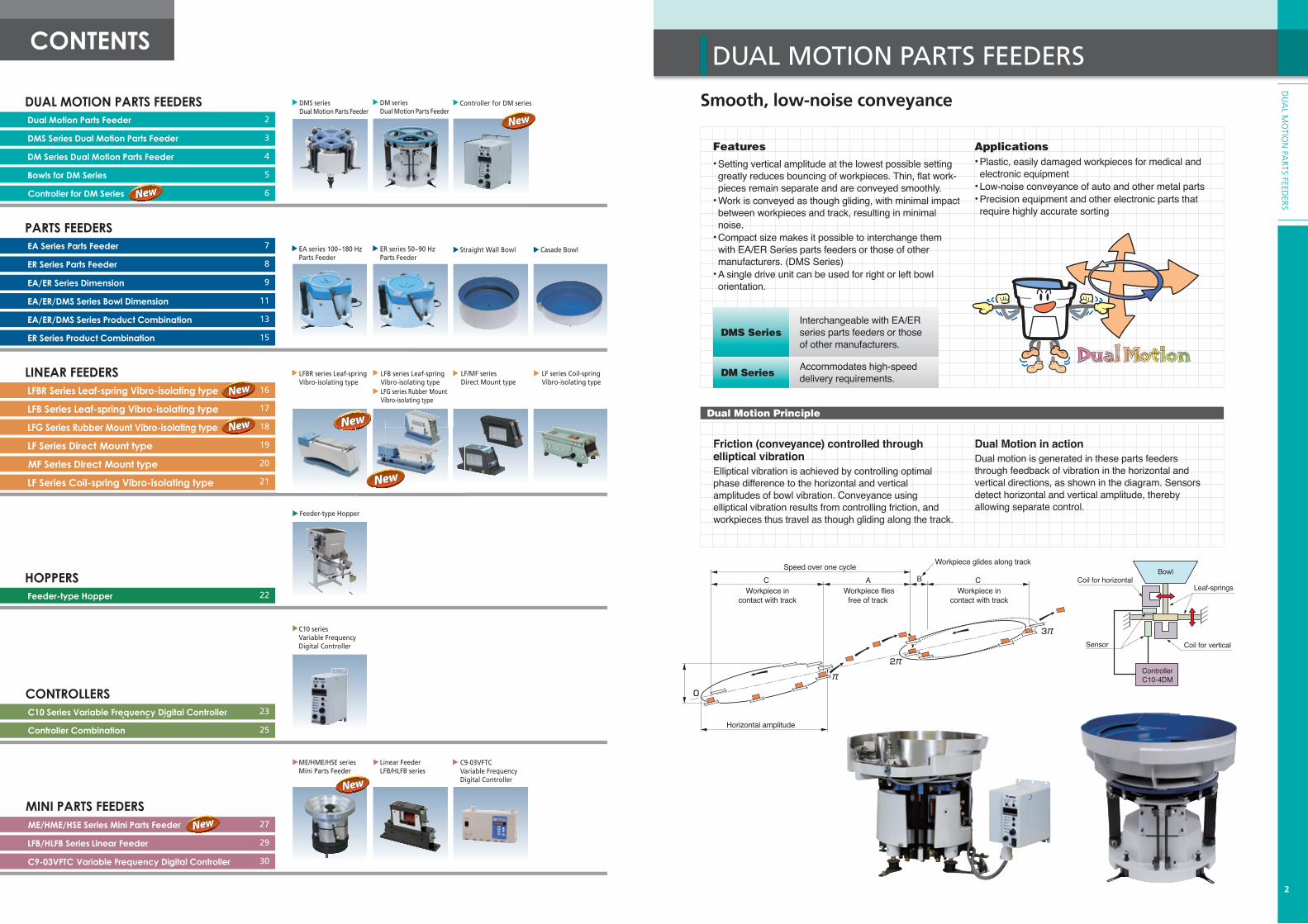
Model H φA φB M φFEA-15 130-133-136 160 150 M8 130EA-20 152-155-158 210 200 M10 170
Model H φA φB M φF L N O P QEA-25 187-190-193 260 250 M12 216 58 50 16 7 10EA-30 215-220-225 310 300 M12 252 85 75 20 7 20EA-38 255-260-265 390 375 M16 324 85 75 20 7 20EA-45 275-280-285 460 450 M16 390 85 75 20 7 20
EA-15/20 EA-25/30/38/45
Power cable 2,000mm
R58R50 7
16
10
M (bowl attachment screw)
φF*
Power cable 2,000mm
L
PQ
O
N
M (bowl attachment screw)
φF*
φB
φA
H
2.3
*F (pitch of rubber mounts)
*F (pitch of rubber mounts)
Mounts can be affixed in any desired alignment.
Unit: mmUnit: mm
Unit: mm Unit: mm
φB
φA
H
2.3
PARTS FEEDERS
PAR
TS F
EED
ERS
Dimensions EA /ER Series
9
PARTS FEED
ERSER-25B/30B/38B/45B ER-55B/65B
ER-75B
Model H φA φB M φF L N O P QER-25B 194-198-202 260 250 M12 216 58 50 16 7 10ER-30B 218-225-232 310 300 M12 252 85 75 20 7 20ER-38B 257-264-271 390 375 M16 324 85 75 20 7 20ER-45B 280-286-292 460 450 M16 390 85 75 20 7 20
Unit: mm
Unit: mm
O *F (pitch of rubber mounts)
Power cable 2,000mm
P
M (bowl attachment screw)
φF*
LQ
N
φB
φA
H2.
3
*F (pitch of rubber mounts)
Power cable 2,000mm
φB
φA
H
3.2
Unit: mm
Unit: mm
Unit: mm
M (Bowl setting screw)
φF*
φ D
Mounts can be affixed in any desired alignment.
φA
φB
H3.
2
Power cable 2,000mm
R140
R125 9
25
30
*F (pitch of rubber mounts)
M (bowl attachment screw)
φF*
φ D
4-M12
30 °
Model H φA φB φD M φFER-55B 312-321-330 560 550 460 M20 450ER-65B 312-321-330 660 650 580 M20 550ER-75B 312-321-330 760 750 640 M20 640
PARTSDiagrams show counter-clockwise orientation
Unit: mm
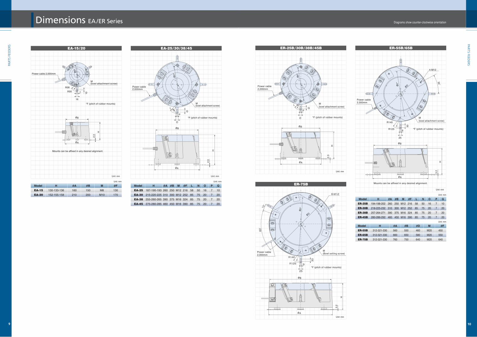
Straight Wall Bowls
T φA
φd
φDφE
H
P
(G)
h
B
T
φd
φA
N
H
P
(G)
hB 12
.9
φD
φEφF
4
65˚
Approx. Model φA B φD φE G H P h φd T Weight Capacity
(kg) ( )EA/DMS-15 150 12 73.1 89.1 22 70 18 56 8.2 1.5 1.1 0.1EA/DMS-20 200 18 104 120 25 85 24 69 10.2 1.5 1.8 0.2EA/ER/DMS-25 250 20 143 159 27 100 30 83 12.2 2 3.2 0.5EA/ER/DMS-30 300 25 174.7 190.7 35 125 36 101 12.2 2 5.0 0.8EA/ER/DMS-38 375 35 216 232 43 155 46 129 16.2 2 8.0 1.7EA/ER/DMS-45 450 40 282.5 298.5 52 190 56 156 16.2 3 15.0 3.0
Unit: mm
Approx. Model φA B φD φE φF G H P h φd T Weight Capacity
(kg) ( )ER-55B 550 55 288.5 318.5 309.2 78 266 76 221 25 3 28 5ER-65B 650 65 373 406.4 397.2 88 311 90 258 25 3 39 10ER-75B 750 75 477.8 508 498.7 99 366 108 303 25 3 54 15
60
50
40
30
20
10
00 10 20 30 40 50 60 70 80 90
Workpiece length (mm)
Workpiece diameter (mm)
ER-75B
ER-65B
ER-55B
EA/ER/DMS-45EA/ER/DMS-38
EA/ER/DMS-30EA/ER/DMS-25EA/DMS-20EADMS-15
Notes 1) Bowls are made of stainless steel, and standard color is differ from color of pictures above. 2) Bowls available with clockwise or counter-clockwise orientation. 3) Capacity varies according to the type of workpiece. *When supplied unprocessed, neither inside nor outside has been surface-treated.
Track circuits: 2 ・ 1/4
Detail of point N
Straight wall Bowl Selection Guide
Unit: mm
PAR
TS F
EED
ERS
Bowl Dimensions EA/ER/DMS Series
11
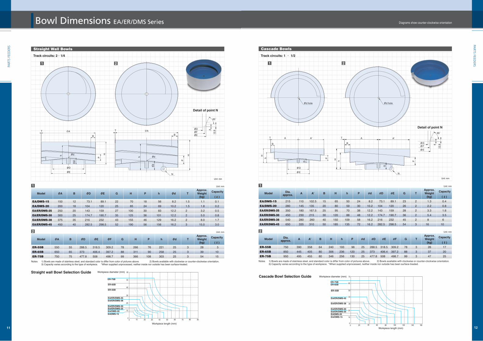
Cascade Bowls
φd hole
A'
G
Hh P
AT
B
φDφE
65˚
12.9
φDφFφE
4
Unit: mm Approx. Model Dia. A A’ B H h P φd φD φE G T Weight
Capacity
approx.
(kg) ( )EA/DMS-15 215 110 102.5 15 65 50 24 8.2 73.1 89.1 23 2 1.3 0.4EA/DMS-20 280 145 135 20 80 59 30 10.2 104 120 26 2 2.2 0.8EA/ER/DMS-25 350 180 167.5 25 95 70 38 12.2 143 159 28 2 3.3 1.6EA/ER/DMS-30 450 230 215 30 120 88 48 12.2 174.7 190.7 36 2 5.4 3.5EA/ER/DMS-38 540 280 260 40 150 109 58 16.2 216 232 45 2 8 6 EA/ER/DMS-45 650 335 310 50 185 135 72 16.2 282.5 298.5 54 3 16 10
Unit: mm
Approx. Model Dia. A A’ B H h P φd φD φE φF G T Weight Capacity
approx.
(kg) ( )ER-55B 750 390 358 64 240 193 96 25 288.5 318.5 309.2 78 3 26 17ER-65B 850 445 405 80 306 236 120 25 373 406.4 397.2 88 3 37 20ER-75B 950 495 455 80 346 256 130 25 477.8 508 498.7 99 3 47 25
70
60
50
40
30
20
10
00 20 40 60 80 100 120 140
ER-75BER-65B
ER-55B
EA/ER/DMS-45
EA/ER/DMS-38
EA/ER/DMS-30EA/ER/DMS-25EADMS-20EA/DMS-15
Workpiece diameter (mm)
Workpiece length (mm)160
Cascade Bowl Selection Guide
Track circuits: 1 ・ 1/2
Detail of point N
T
PhH
φd hole
A
B
N
G
A'
Notes 1) Bowls are made of stainless steel, and standard color is differ from color of pictures above. 2) Bowls available with clockwise or counter-clockwise orientation. 3) Capacity varies according to the type of workpiece. *When supplied unprocessed, neither inside nor outside has been surface-treated.
Unit: mm
PAR
TS FEEDER
S
12
Diagrams show counter-clockwise orientation

1 EA/DMS-15+LFB-300 2 EA/DMS-20+LFB-300 3 EA/ER/DMS-25+LFB-400
φ150
(15)
1527
030
0
1510
0(6
5)
(15) 15300270
5-M11
(182
)
(212
)t1
2(1
30)
70
250
70
7 EA/ER/DMS-38+LFB-550 8 EA/ER/DMS-38+LFG-750
Power cable 2,000mm
Sensor for overflow
(350)
t12
(27
5)
(198
)10
0
(310
)
130
157011
0
420
450
∅250
5-∅13
370 15400
(15)
(15)
15
Sensor for overflow
Power cable 2,000mm
155
(475)
165t19
(438
)(
264)
(40
0)
165
(475)
155
(438
)
(264
)t1
9
(40
0)
80 1513
0
620
(15)
650
φ375
15
5-φ13570 15(15)
600
Sensor for overflow
Power cable 2,000mm
φ375
80
130
620
650
570
600
15
15
15(15)
(15) 5-φ13
Sensor for overflow
Power cable 2,000mm
Power cable 2,000mm
Sensor for overflow
φ150φ200
5-M11
(15)
15 1510
0(6
5)
(15) 15320350
370
400
(222
)
250
(252
)(1
55)
85t1
2 70
PAR
TS F
EED
ERS
Linear Feeder Combinations EA/ER/DMS Series
13
4 EA/ER/DMS-25+LFG-600 5 EA/ER/DMS-30+LFB-400 6 EA/ER/DMS-30+LFG-600
9 EA/ER/DMS-45+LFB-550 10 EA/ER/DMS-45+LFG-750
Unit: mm
PAR
TS FEEDER
S
14
Diagrams show counter-clockwise orientation
370400
450
420
110
70
φ250
15
15
(15)
(15)
15
5-φ13
130
(310
)10
0
(350)
(198
)t1
2
(27
5)
Power cable 2,000mm
Sensor for overflow 500
470
15(
15)
7011
015
125
(22
5)t
16(
366)
130
(32
5)
(350)
φ300
15420(15)450
Sensor for overflow
Power cable 2,000mm
5-φ13420450
470
500
110
70
φ300
15
(15)
(15)
1515
5-φ13
(225
)12
5(3
75)
(350)
130
t16
(32
6)
Sensor for overflow
Power cable 2,000mm
85
140
15
t19
(286
)19
0
(495
)
(475)
700
670
(15)
15
φ450
620 15(15)650
(43
5)
165
5-φ13
Sensor for overflow
Power cable 2,000mm
φ450
165
190
(495
)
(475)
(286
)
85
140
670
700
620650
1515
(15)
(15)
15
t19
(43
5)
5-φ13
Sensor for overflow
Power cable 2,000mm

(625)
(32
1)29
2
(63
2)
(55
5)
225
t19
(593
)
t19
253
(321
)
(51
5)
225
(625)
φ550
820
850
140
85 1515
770
(15)
15(15)800
5-φ13
Sensor for overflow
Power cable 2,000mm
85
140
15
920
950
φ650
15
870900
(15) 15
(15) 5-φ13
Sensor for overflow
Power cable 2,000mm
225
(625)
(32
1) (56
5)
352
(69
2)
t19
140
1050
1020
(15)
15
φ750
1585
1000970(15) 15
5-φ13
Sensor for overflow
Power cable 2,000mm
Notes:All diagrams above show straight wall bowls, however combinations are also possible with track-stepped bowls. (Only bowl diameter and chute exit height vary; all other dimensions are the same for both types of bowl)A wide range of combinations is possible, depending on the type of workpiece. We are happy to discuss customers’ individual requirements.
1112
13
ER-55B
ER-65B
ER-75B
Model EA/DMS15
EA/DMS-20
EA/ER/DMS-25
EA/ER/DMS-30
EA/ER/DMS-38
EA/ER/DMS-45
12
3 45 6
79
Parts FeederLinear Feeder Model
Leaf-spring vibro-isolating Rubber-mount vibro-isolating
11 ER-55B+LFG-900 12 ER-65B+LFG-900
13 ER-75B+LFG-900
Low-reaction force linear feeder with less floor reactionA leaf-spring vibro-isolating type linear feeder with reduced floor reaction. We enabled low-reaction force, high accuracy and smooth parts conveyance through our review of the drive unit mechanism in detail.
LFBR-350B /450B/600B Dimensions
Chute Specifications, Including Basic Position
Model Max. length Max. width Min. thickness Weight range (kg) Basic position (at max. chute length) L1 L2 L3 L4 L5 LFBR-350B 350 40 9 0.4~1.2 110~150 90 30~110 39 67.5 LFBR-450B 450 45 12 1.2~2.3 150~190 110 70~150 46 82 LFBR-600B 600 55 14 2.3~4.0 200~250 150 90~200 55 108
Model A B C D E F G H I J K L M LFBR-350B 70 170.5 12 93.5 45 13 12 M5 110 21 55 15 M8 LFBR-450B 80 205 20 107.5 55 13 14 M6 130 38 60 12 M8 LFBR-600B 95 274.5 25.5 133 75 16.5 19 M6 190 46 75 14 M10
Unit: mm
Unit: mm
LFBR Series
Dimensions Chart
Specifications
Features• Floor reaction force reduce design By reviewing the drive unit mechanism, floor reaction force has been drastically reduced, compared with the existing leaf-spring vibro-isolating type.• Leaf spring and Core gap adjustment are unnecessary No troublesome leaf-spring adjustment or even core gap adjustment is necessary, by using the available C9, C10 series variable frequency digital controllers. • No vibrational interference Because of the middle frequency vibration range (between Full and Have wave), vibrational interference will not occur, when used in combination with other parts feeders. • Uniform chute vibration angle The entire chute vibration angle become uniformly, and has improved the parts conveyance become much more smoothly. • Low power consumption Driven near the resonance range enable to gain sufficient stroke in low current.
810
LFB-300 LFB-400 LFB-550 LFG-600 LFG-750 LFG-900
Unit: mm
Unit: mm
Compatiblecontroller
AC200VAC100V
C10-1VF / C10-1VFEF C10-1VF+C10-TR / C10-1VFEF+C10-TR
200 0.12 0.14 0.2 95~120 75~100 75~90 3.5 5.5 10.5 12 15 15 0.60 0.65 0.75 0.75 x 3 cores
high accuracy and smooth parts conveyance through our review of the d
L
FeaturesFeaturese t r s• gngnesigesigdedece ceducducredredce rce rFloor reaction forcFloor reaction forco r a n o c r d c e g
onactiotireaoor floflsm,anisichahmecnit mite un By reviewing the driveB i i th d iy e e e r e n m c a s o a owithithd wdaredaredmpampacomcomd, cd cuceceeduedy rerecallycallforce has been drasticforce has been drastico e a b e d s c y e u c m a d w
I J
D
LK
AFE ECB
GG
9-H
4-M
Power cable 2,000mm
Feed direction
ModelRated voltage V
Rated current A
Vibration frequency Hz
Drive unit weight kg
Leaf-spring angle degree
Max. amplitude mm
Cross section area of power cable mm2
15
PAR
TS F
EED
ERS
LFBR-350B LFBR-450B LFBR-600B
(625)
(32
1)29
2
(63
2)
(55
5)
225
t19
(593
)
t19
253
(321
)
(51
5)
225
(625)
φ550
820
850
140
85 1515
770
(15)
15(15)800
5-φ13
Sensor for overflow
Power cable 2,000mm
85
140
15
920
950
φ650
15
870900
(15) 15
(15) 5-φ13
Sensor for overflow
Power cable 2,000mm
225
(625)
(32
1) (56
5)
352
(69
2)
t19
140
1050
1020
(15)
15
φ750
1585
1000970(15) 15
5-φ13
Sensor for overflow
Power cable 2,000mm
Notes:All diagrams above show straight wall bowls, however combinations are also possible with track-stepped bowls. (Only bowl diameter and chute exit height vary; all other dimensions are the same for both types of bowl)A wide range of combinations is possible, depending on the type of workpiece. We are happy to discuss customers’ individual requirements.
1112
13
ER-55B
ER-65B
ER-75B
Model EA/DMS15
EA/DMS-20
EA/ER/DMS-25
EA/ER/DMS-30
EA/ER/DMS-38
EA/ER/DMS-45
12
3 45 6
79
Parts FeederLinear Feeder Model
Leaf-spring vibro-isolating Rubber-mount vibro-isolating
11 ER-55B+LFG-900 12 ER-65B+LFG-900
13 ER-75B+LFG-900
Low-reaction force linear feeder with less floor reactionA leaf-spring vibro-isolating type linear feeder with reduced floor reaction. We enabled low-reaction force, high accuracy and smooth parts conveyance through our review of the drive unit mechanism in detail.
LFBR-350B /450B/600B Dimensions
Chute Specifications, Including Basic Position
Model Max. length Max. width Min. thickness Weight range (kg) Basic position (at max. chute length) L1 L2 L3 L4 L5 LFBR-350B 350 40 9 0.4~1.2 110~150 90 30~110 39 67.5 LFBR-450B 450 45 12 1.2~2.3 150~190 110 70~150 46 82 LFBR-600B 600 55 14 2.3~4.0 200~250 150 90~200 55 108
Model A B C D E F G H I J K L M LFBR-350B 70 170.5 12 93.5 45 13 12 M5 110 21 55 15 M8 LFBR-450B 80 205 20 107.5 55 13 14 M6 130 38 60 12 M8 LFBR-600B 95 274.5 25.5 133 75 16.5 19 M6 190 46 75 14 M10
Unit: mm
Unit: mm
LFBR Series
Dimensions Chart
Specifications
Features• Floor reaction force reduce design By reviewing the drive unit mechanism, floor reaction force has been drastically reduced, compared with the existing leaf-spring vibro-isolating type.• Leaf spring and Core gap adjustment are unnecessary No troublesome leaf-spring adjustment or even core gap adjustment is necessary, by using the available C9, C10 series variable frequency digital controllers. • No vibrational interference Because of the middle frequency vibration range (between Full and Have wave), vibrational interference will not occur, when used in combination with other parts feeders. • Uniform chute vibration angle The entire chute vibration angle become uniformly, and has improved the parts conveyance become much more smoothly. • Low power consumption Driven near the resonance range enable to gain sufficient stroke in low current.
810
LFB-300 LFB-400 LFB-550 LFG-600 LFG-750 LFG-900
Unit: mm
Unit: mm
Compatiblecontroller
AC200VAC100V
C10-1VF / C10-1VFEF C10-1VF+C10-TR / C10-1VFEF+C10-TR
200 0.12 0.14 0.2 95~120 75~100 75~90 3.5 5.5 10.5 12 15 15 0.60 0.65 0.75 0.75 x 3 cores
high accuracy and smooth parts conveyance through our review of the d
L
FeaturesFeaturese t r s• gngnesigesigdedece ceducducredredce rce rFloor reaction forcFloor reaction forco r a n o c r d c e g
onactiotireaoor floflsm,anisichahmecnit mite un By reviewing the driveB i i th d iy e e e r e n m c a s o a owithithd wdaredaredmpampacomcomd, cd cuceceeduedy rerecallycallforce has been drasticforce has been drastico e a b e d s c y e u c m a d w
I J
D
LK
AFE ECB
GG
9-H
4-M
Power cable 2,000mm
Feed direction
ModelRated voltage V
Rated current A
Vibration frequency Hz
Drive unit weight kg
Leaf-spring angle degree
Max. amplitude mm
Cross section area of power cable mm2
15
PAR
TS F
EED
ERS
LFBR-350B LFBR-450B LFBR-600B

Uniform vibration with no need for adjustmentUse of a variable frequency controller eliminates the need for leaf-spring and core-gap adjustments. Provides uniform vibration with no adjustments necessary, and is easily installed to link up with other equipment, greatly improving ease of use. Can accommodate heavier chute weights and longer overhangs, to widen scope for applications. The drive unit is slim, and with virtually no vibration interference it can easily be combined with parts feeders, to suit wide-ranging combinations. The three models in this series can be used selectively to handle all sizes and shapes of workpiece.
LFB-300/400/550 Dimensions
Features• Simple, uniform vibration Use with heavier chutes and longer overhangs opens a wider range of applications. Consistent, uniform vibration is supplied without the need for adjustment.
• Energy saving type Energy consumption cut by half, compared with our earlier models.
Feed direction
W K F
RII
4-φd drilled holes
9-M screw
H
(G)(A)E
CN
LB
P
O
SpecificationsModel
Rated voltage V
Rated current A
Vibration frequency Hz
Drive unit weight kg
Leaf-spring angle degree
Max. amplitude mm
Cross section area of power cable mm2
Compatiblecontroller
Dimensions Chart Model A B C E F G H I K L M N O P
LFB-300 57 135 97 124 65 150 24 45 55 110 5 16 3 10
LFB-400 65 160 120 145 75 180 28 55 60 130 6 16 5 15
LFB-550 79 230 143 200 90 255 38 75 75 190 6 19 5 20
R W d
15 38 6
15 42 7
20 52 9
Unit: mm
Chute Specifications, Including Basic Position
LFB Series
Unit: mm
Model Max. length Max. width Min. thickness Weight range (kg) Basic position (at max. chute length)
L1 L2 L3 L4 L5 LFB-300 300 50 6 0.4~1.0 66 110 40 124 3
LFB-400 400 50 10 0.8~2.0 105 150 70 145 5
LFB-550 550 65 14 1.4~3.5 140 210 85 200 5
AC200V
AC100V
LFB-300 LFB-400 LFB-550
200
0.04 0.08 0.15
90~120 80~110 75~100
3.0 5.0 10.0
15
0.6 0.65 0.75
0.75 × 3cores C10-1VF / C10-1VFEF
C10-1VF+C10-TR / C10-1VFEF+C10-TR
17
LIN
EAR
FEE
DER
S
L1 L4
L5 L3
L2
Power cable 2,000mm
Accommodates a wide range of chutes for ideal conveyanceThe variable frequency controller installed as standard eliminates need for leaf-spring and core-gap adjustments. Easy installation and coordination make it much easier to use, and by adjusting position of the rear-end weight, conveyance irregularities can be quickly and easily eliminated. With minimal lateral movement, there is virtually no vibration interference, making it easy to combine with parts feeders for stabilized delivery. The three models in this series allow a full range of equipment combinations, and cover all shapes and sizes of workpiece. A leaf-spring vibro-isolating type linear feeder with reduced floor reaction.We enabled low-reaction force, high accuracy and smooth parts conveyance through our review of the drive unit mechanism in detail.
LFG-400/550/700 Dimensions
Feed direction
W K F (A)
(G)
I Ib
R
7
9-M screw
H
E
LB
PO
C2
LFG SeriesL0
L1 L4 L2
L3 L5
Chute Specifications, Including Basic PositionModel
LFG-600
LFG-750
LFG-900
Model
LFG-600
LFG-750
LFG-900
Max. length Max. width Min. thickness Weight range (kg) 600 50 10 1.4~3.6 750 65 14 2.2~5.4 900 75 18 4.0~9.8
L0 L1 L2 L3 L4 L5 600 180 275 29 145 6 750 220 330 74 200 16 900 260 390 92 250 18
Basic position (at max. chute length)
Unit: mm
Specifications
AC200VAC100V
LFG-600 LFG-750 LFG-900
200 0.2 0.37 0.41 80~110 80~110 80~110 7.4 13.2 19.6 15 0.65 0.75 0.9 0.75 × 3cores C10-1VF / C10-1VFEF C10-1VF+C10-TR / C10-1VFEF+C10-TR
ModelRated voltage V
Rated current A
Vibration frequency Hz
Drive unit weight kg
Leaf-spring angle degree
Max. amplitude mm
Cross section area of power cable mm2
Compatiblecontroller
with parts feeders for stabilized delivery. The three models in this series allow a shapes and sizes of workpiece. A leaf-spring vibro-isolating type linear feeder wforce, high accuracy and smooth parts conveyance through our review of the dr
Features• Simple, uniform vibration Use with heavier chutes and longer overhangs opens a wider range of applications. Adjustment is made by positioning the rear-end weight, so conveyance can easily be kept uniform without expert skills.• Energy saving type Energy consumption cut by half, compared with our earlier models.
Features• Applicable longer and wider linear chutes. Because new LFG series have longer body from conventional models, more long and wide chutes can be applicable.• Stable vibrating conveyance It prevents move of body caused by vibration with using original vibration isolation rubber. • Withstand load improved Withstand load improved by applying a long chute • Almost same size of drive unit compared with conventional size. Ability improved with same size from conventional size.
(Unit: mm)
LFG-600 Dimensions
LFG-750 Dimensions
LFG-900 Dimensions
MAX60
410
122
250
(144
)
30 12
418
140 110
85
90
27
125
69
80
230
92
10
215
5815
32065320
400
4-φ12
94.5
±0.3
(Par
alleli
smbe
low 0.
3mm)
Core gap0.8~0.9
Power cable 2,000mm
2×φ7For Transporting volts
4-M6
MAX50
276
84
145
210 12(1
02)
1158068
7560
15
48
58
125
66
10
115
20290296
40 1010
4013
4-φ10
69±0
.3(Pa
ralleli
smbe
low 0.3
mm)
Power cable 2,000mm
4-M6
2×φ6For Transporting volts
Core gap0.7~0.8
Unit: mm
Unit: mm
Unit: mm
4-φ10
MAX60
348
110
200
12
346
25
134
100
80
90
26
58
70
180
80
10
158
5014
265
33050265
75
(132
)
2×φ6For Transporting volts
Power cable 2,000mm
4-M6
Core gap0.8~0.9
84±0
.3(P
aralle
lism
below
0.3 m
m)
Feed direction
Feed direction
Feed direction

LINEAR FEEDERS
Simple and compact. Handles a wide range of micro-sized and precision partsDeveloped for stabilized delivery of non-specialized micro-sized and precision parts, this series uses a small, electromagnetic drive unit that is simple and compact. Unmounted, with full wave operation to give excellent conveyance capacity for small volumes of non-specialized micro-sized workpieces. Maintenance is very straightforward and minimizes costs.
Specifications
LF-02 /04 Dimensions
A H
4-J
B
EI R
O
CQ
Power cable 1,000mm
2-M
20°
L P
Features• Handles a wide range of small parts Handles a wide range of non-specialized micro-sized, precision parts• Simple and low cost Provides a simple, low-cost solution for small-volume applications.• Easy, convenient installation Compact design allows easy, convenient installation.
Dimensions Chart Model A B C E H I J L M O P Q R LF-02 22 approx. 81 44.3 65 15 40 M3 40 M4 16 15 9 10 LF-04 32 approx. 101 57.3 80 20 50 M4 55 M5 21 15 12 12
Unit: mm
Unit: mm
Model Rated Voltage (V) Rated Current (A) Vibration frequency (Hz) Weight (kg) Standard compatible controllers LF-02 100/110 0.12 100~180(*100/120) 0.44 LF-04 100/110 0.22 100~180(*100/120) 1.0
Chute Specifications Compatible linear feeder Max. length Max. width Max. weight (kg) LF-02 180 20 0.2 LF-04 240 30 0.4
Feed direction
*When C4-5B was used.
C10-1VF/1VFEFC4-5B
EDERS
19
LIN
EAR
FEE
DER
S
Compact yet powerful, for speedy delivery and versatile, longer distance conveyanceA new type of electromagnetic drive unit ideal for use with chutes handling very small, flat, and precision parts. Takes full advantage of merits of half wave operation for smooth conveyance of fragile and easily damaged workpieces.
Specifications
MF-04C /15C Dimensions
Features• Compact yet powerful Small unit size with half wave operation capable of longer distance conveyance. • Speedy delivery, and versatile, longer distance conveyance High vibration frequency and amplitude give speedy delivery, and can meet a range of loner distance conveyance requirements • Easy, convenient installation Compact design takes up little space and allows easy, convenient installation.
Dimensions Chart Model A B C D E L M N O P Q MF-04C 46 106 56 38 62 88 7 9 38 9 3.2 MF-15C 56 160 78 52 100 144 9 16 52 8 3.2
Unit: mm
Unit: mm
Model Voltage (V) Current (A) Vibration (Hz) Weight (kg) Standard compatible controllers
MF-04C 100/110 0.13 50~90(*50/60) 0.6
MF-15C 100/110 0.2 50~90(*50/60) 1.8
Chute Specifications Compatible linear feeder Max. length Max. width Max. weight (kg) MF-04C 300 35 0.4 MF-15C 450 45 1.5
200/220 0.065
200/220 0.1
Power cable 1,000mm
D A
2-φM
20° E O
Q
C
N
PL
B
Feed direction
Note: Chute must straddle drive unit to distribute weight.
*Users are asked to drill holes as required for chute attachment.
*When C4-5B was used.
C10-1VF/1VFEFC4-5B

23
Swift, stable conveyance of high volumes of large workpiecesLarge-capacity electromagnetic drive unit has strong coil springs positioned at front and rear, and drive controlled by amplitude angle adjustment, to give speedy, steady, straight-line delivery of large-sized workpieces. The low-floored half-wave drive provides uniform amplitude and vibration frequency to eliminate irregularities during high-volume conveyance of large workpieces.
Specifications
LF-30/40 Dimensions
Features• Large size feeder provides smooth workpiece delivery Large, vibro-isolating feeder that keeps the flow of workpieces smooth through adjustment of leaf-spring angle. • Fast, stable delivery of high volumes of large workpieces Extremely high conveyance efficiency allows high-volume delivery of large workpieces. • Dial control for free adjustment of conveyance speed By changing the vibration frequency and amplitude with the dial control, delivery speed can be freely adjusted.
Dimensions Chart Unit: mm
Unit: mmChute Specifications Applicable linear feeder Max. length Max. width Max. weight (kg) LF-30 650 120 3.5 LF-40 750 150 5.5
Feed direction
Coil-spring mounts, av. diameter LF-30:φ3.4×φ28×34LF-40:φ4.0×φ28×34
I
F H
4-φ9 AB
DCE
L
10°
K J
Note: Chute must straddle drive unit to distribute weight.
Unit: mm
Model A B C D E F H I J K L M N P LF-30 182.4 156.4 180.4 150.4 410 295 55 380 30 40 190 162 132 30 LF-40 196.4 166.4 186.4 154.4 500 375 55 470 30 40 250 177 147 30
*When C4-5B was used.
LF-30 0˚~20˚ 10˚~30˚ 200/220 1.5 50~90(*50/60) 25 1.25 x 3 core
C10-3VF/3VFEF LF-40 0˚~20˚ 10˚~30˚ 200/220 1.6 50~90(*50/60) 33 C4-5B
Leaf-springadjustment angleα β
Model Weight (kg) Ratedvoltage (V)
Ratedcurrent (A)
Vibrationfrequency (Hz)
Standard compatiblecontroller
Cross section areaof power cable (mm2)
21
LIN
EAR
FEE
DER
S
Power cable 700mm
βα N
PM
15 /30 /60 /100-liter Hopper Dimensions
Feeder trough
Feeder
F
H
S I
4-φG Fixing holes
Hopper
No.×
P
Dimensions Chart, including Feeders Unit: mm
Hopper
Compatible Permissible
capacity Model Parts weight of A B C E F G H I K L ( ) feeders work (*1) (kg) EA-25
15 HPF-15-3815B ER-25B
24 250 350 322 675~ 320 7 270 275 380 381~ EA-30 875
580
ER-30B EA-25 ER-25B EA-30
30 HPF-30-4215B ER-30B
24 300 400 372 775~ 350 7 290 325 420 380~ EA-38 975
580
ER-38B EA-45 ER-45B
60 HPF-60-6030B ER-55B
56 450 600 553 865~ 500 9 400 480 600 430~ ER-65B 1215
780
100 HPF-100-6030B
ER-55B 56 450 600 553 1015~ 500 9 400 480 600 430~
ER-65B 1365
780
Sliding
Electromagnetic N base S T Weight feeder No. x P (kg) Feeder Rated model current (A)
150 5 x 50 310 225 46 CF-2 0.5
150 5 x 50 360 265 50 CF-2 0.5
300 8 x 50 536 (358) 140 CF-3 1.0
300 8 x 50 536 (358) 147 CF-3 1.0
Features• By attaching a feeder to a hopper, parts delivery is extremely smoothly accomplished and running noise is kept extremely low.
Notes *1 Hoppers come in stainless steel only. *2 Vibration frequency: 50~70Hz; rated voltage: 200/220V; compatible controller: C10-1VFEF. (No standard model with 100/110V specifications.) *3 Paint finish: Munsell N7.5 *4 For 15- and 30-liter hoppers, hopper heights come in 5 levels at 50mm intervals: for 60- and 100-liter hoppers, hopper heights come in 8 levels at 50mm intervals. *5 Heavy-duty 60- and 100-liter hoppers (permissible total work weight 112kg) are available as non-standard models. * Manufactured to order.
*
*
Unit: mm
Feeder-Type Hoppers
22

Digital control operated in ‘Analog’ way A completely new type of digital controller that can be used with the full line-up of feeders, from high frequency mini parts feeders to small electromagnetic feeders and large size models. With ‘analog-style’ operation it can be adjusted very swiftly.With an auto-tuning function that eliminates the need for frequency adjust-ment, and convenient digital settings and display, drive units can be operated to their full potential.
C10-1VF/1VFEF/3VF/3VFEF Dimensions
C10-5VF/5VFEF Dimensions
C10-TR Dimensions
Stroke
Frequency
SoftStart
OnDelay
OffDelay
Function
SAVE
SET
ON
OFF
AUTO FREQRUN ALARM
MODEL C10-5VFEF
ALARMRUN AUTO FREQ
OFF
ON
SET
SAVE
Function
OffDelay
OnDelay
SoftStart
Frequency
Stroke
MODEL C10-TR
Unit: mm
Unit: mm
Unit: mm
Features• Auto-tuning function eliminates leaf- spring adjustment (C10-1VFEF, 3VFEF, 5VFEF)This digital equipment has a special advanced vibration frequency auto-tuning function. It automatically tracks resonance point changes not only from changes to input volume of workpieces, but also from mechanical changes over time, to deliver optimal vibration at all times. No leaf-spring adjustment or even frequency adjustment is necessary, thereby boosting operation efficiency and saving energy.
• Digital setting and display makes settings easy to manage.Amplitude, drive frequency, output voltage notches are all set and displayed digitally, for easy management.
• Constant amplitude control matched to workpieces or materials (C10-1VFEF, 3VFEF, 5VFEF)Amplitude can be set digitally, and an amplitude sensor allows drive at constant amplitude suited to the workpieces under conveyance.
• Easy-to-use panel designThe frequency, voltage, soft start, on delay and off delay settings needed for parts feeder adjustment are located on a control panel. A rotary encoder allows ‘analog-style’ setting input to be changed to digital values.
• Many external control functionsChoice of four speeds can be made by external signal. Two-step control through external regulating resistance. External volume adjustment via a DC4-20mA signal is also possible.
• CE Marking conformed productRequired to be installed inside the control box treated with Noise filter and IP4X to make product comply to CE Marking.
141(9)
160
140
170
35
φ53059
11945 45 14.5
31.630
140
160
170
15126
141(9)
140
160
170
35
φ5
By using a C10-TR power transformer unit with a standard controller, output voltage can be boosted to run an AC 200 V parts feeder from an AC 100 V power source. This is not applicable for C10-5VF(EF).
※No plug for sensor on C10-1VF/3VF
※No plug for sensor on C10-5VF
※
※
Output
Operatingmodes
Additionalfeatures
Synchronizedpower output
Others
ER-30B,38B,45B ER-30B,38B,45B ER-55B,65B,75B EA-25,30,38,45 ER-55B,65B,75B EA-25,30,38,45 LF-30,40 LF-30,40
Compatible equipment
C10 Series Parts & Functions
ALARM lightLights when -In constant amplitude or auto-tuning mode, output voltage reaches saturation and cannot track set amplitude, or-Error occurs
Stroke
Frequency
SoftStart
OnDelay
OffDelay
Function
SAVE
SET
ON
OFF
AUTO FREQRUN ALARM
RUN lightLights while operating
RUN/STOP buttonOperation can be stopped or started manually
Data display dialSwitches data shown on data display screen
Data display lightsIdentify what is showing on data display screen. LED light indicates display mode; flashing light indicates data modification mode Stroke: voltage (amplitude) percentage displayedFrequency: frequency displayed Soft start: Soft start time displayedOn delay: On delay time displayed*Off delay: Off delay time displayed*Function: Function detail displayed
AUTO FREQ light*Lights during auto-tuning modeFlashes during initial auto-adjusting
AUTO FREQ button*Activates/de-activates auto-tuning
Data display screenDisplays voltage/amplitude (%), frequency, settings, and error codes
SAVE buttonIn settings mode, records data modifications
SET buttonSwitches between display mode and data modification mode In data modification mode for stroke and frequency, press again to switch the position of a figure
Settings encoderModifies settings in data display screen
*You need a sensor in order to use functions with asterisk. These functions are not available on C10-1VF, 3VF, 5VF models (exclusive to VFEF models)
Model C10-5VF C10-3VF C10-1VF C10-5VFEF C10-3VFEF C10-1VFEF
Input power source AC100~120V±10%, AC200~230V±10%, 50/60Hz Control system PWM system
Voltage 0~190V (for AC 200V input) 0~95V (for AC 100V input)
Optional unit C10-TR allows output voltage in 0~190V range (Except C10-5VF(EF)) even with AC100V input Half wave: 45~90Hz, Full wave: 90~180Hz Intermediate wave: 65~120Hz,High frequency: 180~360Hz Max. current 5A 3A 1A 5A 3A 1A Constant voltage mode Frequency, output voltage set manually Constant amplitude mode ̶ Constant amplitude control at set frequency Auto-tuning mode ̶ With frequency auto-tuning, constant amplitude control requires no amplitude setting
Speed selector Selection of up to 4 amplitude settings by means of external signal Start/stop control Start/Stop control by external signal Output signal Output signal synchronized to parts feeder operation Soft start Start-up time 0.2~4.0 secs On/Off delay ̶ Delay 0.2~60secs Sensor power source ̶ For DC 12V, max. 80mA 3P power plug Function ̶ Power output synchronized to parts feeder operation (RUN) Control system ̶ On/Off control Output voltage ̶ As power source input to controller Max. current ̶ 2A Noise tolerant voltage Above 1000V Ambient temperature 0~40°C Ambient humidity 10~90% (no condensation) Weight 1.5kg 0.9kg 0.8kg 1.6kg 1.0kg 0.9kg
Case color U75-70D (Japan Paint Industry Association)
Specifications
Vibration frequency
ER-25BEA-15,20
LFBR-350B,450B,600BLFB-300,400,550LFG-600,750,900
ME-08C,14CHME-08C,14LFB-02,04
HLFB-02,04CLF-02,04
MF-04C,15CHSE-14
ER-25BEA-15,20
LFBR-350B,450B,600BLFB-300,400,550LFG-600,750,900
ME-08C,14CHME-08C,14LFB-02,04
HLFB-02,04CLF-02,04
MF-04C,15CHSE-14
Note: Specifications above are applied for later than ver.4.

Power sourceAC200/220V
Power sourceAC200/220V
Controller for hopper
Hopper
Level switch
Vibrating or Feeder
Sensor amp
Amplitudesensor(Correspoding with only VFEF)
Overflowsensor
Linear Feeder(LFBR,LFB, LFG Series)
Parts Feeder(EA, ER Series)
For source voltage AC200/220V
Single Drive
Twin Drive
Parts Feeder ControllerC10-5VF/3VF/1VF
Parts Feeder ControllerC10-5VFEF/ 3VFEF/ 1VFEF
Linear Feeder ControllerC10-1VF
Linear Feeder ControllerC10-1VF
Power sourceAC200/220V
Parts Feeder(EA, ER Series)
Parts Feeder(EA, ER Series)
Linear Feeder(LFBR,LFB, LFG Series)
Power sourceAC200/220V
Power sourceAC200/220V
Vibrator or Feeder
Sensor amp
Hopper Overflow sensor
Controller for hopper
Amplitudesensor(Correspoding with only VFEF)
Level switch
Parts Feeder ControllerC10-5VFEF/ 3VFEF/ 1VFEF
Power sourceAC100/110V
Power sourceAC100/110V
Hopper
Controller for hopper
Level switch
Vibrating or Feeder
Amplitudesensor(Correspoding with only VFEF)
Sensor amp
Linear Feeder(LFBR,LFB, LFG Series)
Parts Feeder(EA, ER Series)
Power sourceAC100/110V
Power sourceAC100/110V
Power sourceAC100/110V Controller
for hopper
Hopper
Level switch
Vibrator or Feeder
Sensor amp
Amplitudesensor(Correspoding with only VFEF)
Overflow sensor
Parts Feeder(EA, ER Series)
Parts Feeder(EA, ER Series)
Linear Feeder(LFBR,LFB, LFG Series)
For source voltage AC100/110V
Single Drive
Twin Drive
Optional Unit
C10-TR
Optional Unit
C10-TR
Optional Unit
C10-TR
Optional Unit
C10-TR
Parts FeederController
C10-3VF/1VF
Parts FeederController
C10-3VFEF/1VFEF
Linear FeederControllerC10-1VF
Parts FeederController
C10-3VFEF/1VFEF
Linear FeederControllerC10-1VF
Amplitude sensor
Overflowsensor
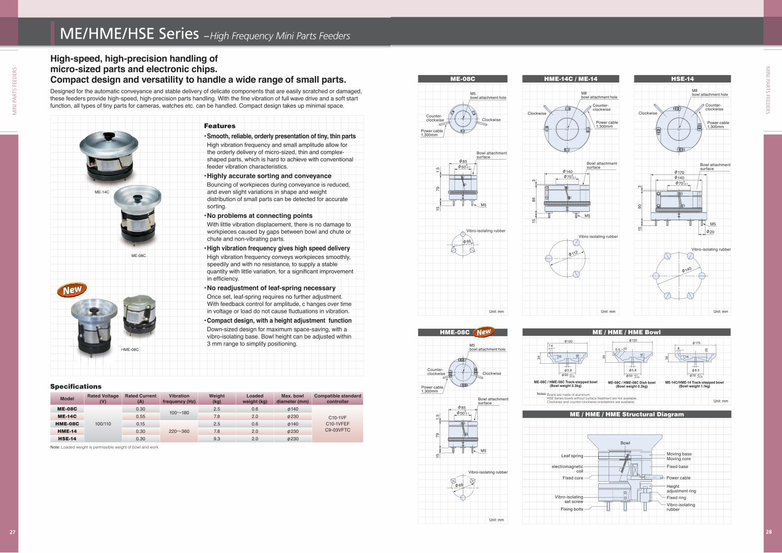
High-speed, high-precision handling of micro-sized parts and electronic chips. Compact design and versatility to handle a wide range of small parts.Designed for the automatic conveyance and stable delivery of delicate components that are easily scratched or damaged, these feeders provide high-speed, high-precision parts handling. With the fine vibration of full wave drive and a soft start function, all types of tiny parts for cameras, watches etc. can be handled. Compact design takes up minimal space.
Features• Smooth, reliable, orderly presentation of tiny, thin parts High vibration frequency and small amplitude allow for the orderly delivery of micro-sized, thin and complex- shaped parts, which is hard to achieve with conventional feeder vibration characteristics. • Highly accurate sorting and conveyance Bouncing of workpieces during conveyance is reduced, and even slight variations in shape and weight distribution of small parts can be detected for accurate sorting. • No problems at connecting points With little vibration displacement, there is no damage to workpieces caused by gaps between bowl and chute or chute and non-vibrating parts.• High vibration frequency gives high speed delivery High vibration frequency conveys workpieces smoothly, speedily and with no resistance, to supply a stable quantity with little variation, for a significant improvement in efficiency.• No readjustment of leaf-spring necessary Once set, leaf-spring requires no further adjustment. With feedback control for amplitude, c hanges over time in voltage or load do not cause fluctuations in vibration. • Compact design, with a height adjustment function Down-sized design for maximum space-saving, with a vibro-isolating base. Bowl height can be adjusted within 3 mm range to simplify positioning.
Note: Loaded weight is permissible weight of bowl and work.
Specifications
Model Rated Voltage Rated Current Vibration Weight Loaded Max. bowl Compatible standard (V) (A) frequency (Hz) (kg) weight (kg) diameter (mm) controller ME-08C 0.30
100~180 2.5 0.6 φ140
ME-14C 0.55 7.8 2.0 φ230 C10-1VF HME-08C 100/110 0.15 2.5 0.6 φ140 C10-1VFEF HME-14 0.30 220~360 7.8 2.0 φ230 C9-03VFTC
HSE-14 0.30 9.3 2.0 φ230
ME-14C
ME-08C
14C
HME-08CH
ME-08C HME-14C / ME-14 HSE-14
ME / HME / HME Structural Diagram
1.5
7915
8615
15
3
3
M5
M5
M5
φ140φ140
φ112
φ66
φ140
φ70
φ50φ85
φ70
φ20
φ170
M8bowl attachment hole
M5 bowl attachment hole
Power cable 1,300mm
Power cable 1,300mm
Power cable 1,300mm
Vibro-isolating rubberVibro-isolating rubber
Clockwise Clockwise
Clockwise
Bowl attachment surface
Bowl attachment surface
Bowl attachment surface
Counter-clockwise
Counter-clockwise
90
Vibro-isolating rubber
Counter-clockwise
Unit: mmUnit: mm Unit: mm
Unit: mm
0-0.1
HME-08C
1.5
7915
M5
φ66
Vibro-isolating rubber
Clockwise
Bowl attachment surface
Counter-clockwise
φ50φ85
0-0.1
0-0.1
0-0.1
ME / HME / HME Bowl
Bowls are made of aluminum. HSE Series bowls without surface treatment are not available.Clockwise and counter-clockwise orientations are available.
φ120
100.5
1630
φ5.8φ50
ME-08C / HME-08C Dish bowl(Bowl weight 0.3kg)
+0.1+0.05
φ1207.4
1634 10
φ5.8φ50
ME-08C / HME-08C Track-stepped bowl(Bowl weight 0.3kg)
+0.1+0.05
φ175
φ8.5φ70
8
14
20
36
ME-14C/HME-14 Track-stepped bowl(Bowl weight 1.1kg)
+0.1+0.05
Vibro-isolating rubber
Power cable
Moving baseMoving core
Fixed ring
Height adjustment ring
Fixed base
Vibro-isolatingset screw
Leaf spring
electromagnetic coil
Fixed core
Fixing bolts
Bowl
Notes:
M8bowl attachment hole
Power cable 1,300mm
M5bowl attachment hole
Unit: mm
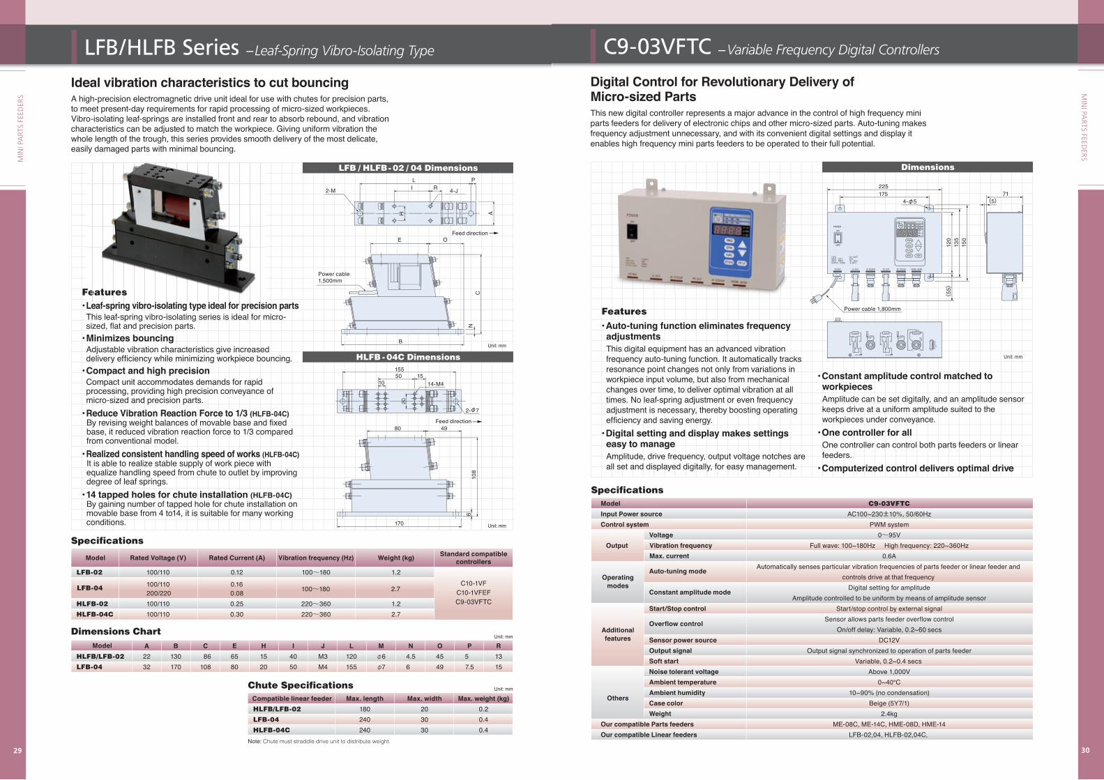
Ideal vibration characteristics to cut bouncingA high-precision electromagnetic drive unit ideal for use with chutes for precision parts, to meet present-day requirements for rapid processing of micro-sized workpieces. Vibro-isolating leaf-springs are installed front and rear to absorb rebound, and vibration characteristics can be adjusted to match the workpiece. Giving uniform vibration the whole length of the trough, this series provides smooth delivery of the most delicate, easily damaged parts with minimal bouncing.
Specifications
LFB / HLFB- 02 / 04 Dimensions
HLFB - 04C Dimensions
Feed direction
Feed direction
2-M
LI R 4-J
P
H A
Power cable1,500mm
155
E O
CN
B
Dimensions Chart
Chute Specifications
Model A B C E H I J L M N O P R HLFB/LFB-02 22 130 86 65 15 40 M3 120 φ6 4.5 45 5 13 LFB-04 32 170 108 80 20 50 M4 155 φ7 6 49 7.5 15
Unit: mm
Unit: mm
Compatible linear feeder Max. length Max. width Max. weight (kg) HLFB/LFB-02 180 20 0.2 LFB-04 240 30 0.4 HLFB-04C 240 30 0.4 Note: Chute must straddle drive unit to distribute weight.
Features• Leaf-spring vibro-isolating type ideal for precision parts This leaf-spring vibro-isolating series is ideal for micro- sized, flat and precision parts.• Minimizes bouncing Adjustable vibration characteristics give increased delivery efficiency while minimizing workpiece bouncing.• Compact and high precision Compact unit accommodates demands for rapid processing, providing high precision conveyance of micro-sized and precision parts.• Reduce Vibration Reaction Force to 1/3 (HLFB-04C) By revising weight balances of movable base and fixed base, it reduced vibration reaction force to 1/3 compared from conventional model. • Realized consistent handling speed of works (HLFB-04C) It is able to realize stable supply of work piece with equalize handling speed from chute to outlet by improving degree of leaf springs.• 14 tapped holes for chute installation (HLFB-04C) By gaining number of tapped hole for chute installation on movable base from 4 to14, it is suitable for many working conditions.
Features• Leaf-spring vibro-isolating type ideal for precision parts This leaf-spring vibro-isolating series is ideal for micro- sized, flat and precision parts.• Minimizes bouncing Adjustable vibration characteristics give increased delivery efficiency while minimizing workpiece bouncing.• Compact and high precision Compact unit accommodates demands for rapid processing, providing high precision conveyance of micro-sized and precision parts.
Model Rated Voltage (V) Rated Current (A) Vibration frequency (Hz) Weight (kg) Standard compatible controllers LFB-02 100/110 0.12 100~180 1.2
HLFB-02 100/110 0.25 220~360 1.2 HLFB-04C 100/110 0.30 220~360 2.7
LFB-04 100/110 0.16200/220 0.08 2.7100~180
C10-1VFC10-1VFEFC9-03VFTC
108
6
50 15
2-φ7
10 14-M4
80
170
49
Unit: mm
Unit: mm
FeaturesFe t r sLeaf spring vibro isolating type ideal for precise f p n v r i o i p e f e s
Digital Control for Revolutionary Delivery of Micro-sized PartsThis new digital controller represents a major advance in the control of high frequency mini parts feeders for delivery of electronic chips and other micro-sized parts. Auto-tuning makes frequency adjustment unnecessary, and with its convenient digital settings and display it enables high frequency mini parts feeders to be operated to their full potential.
Dimensions
Unit: mm
• Constant amplitude control matched to workpieces Amplitude can be set digitally, and an amplitude sensor keeps drive at a uniform amplitude suited to the workpieces under conveyance.
• One controller for all One controller can control both parts feeders or linear feeders.
• Computerized control delivers optimal drive
Specifications Model Input Power source Control system Voltage Output
Auto-tuning mode
Constant amplitude mode
Start/Stop control
Overflow control Sensor power source Output signal Soft start Noise tolerant voltage Ambient temperature Ambient humidity Case color Weight Our compatible Parts feeders Our compatible Linear feeders
C9-03VFTC
AC100~230±10%, 50/60Hz PWM system 0~95V Full wave: 100~180Hz High frequency: 220~360Hz 0.6A Automatically senses particular vibration frequencies of parts feeder or linear feeder and controls drive at that frequency Digital setting for amplitude Amplitude controlled to be uniform by means of amplitude sensor Start/stop control by external signal Sensor allows parts feeder overflow control On/off delay: Variable, 0.2~60 secs DC12V Output signal synchronized to operation of parts feeder Variable, 0.2~0.4 secs Above 1,000V 0~40℃ 10~90% (no condensation) Beige (5Y7/1) 2.4kg ME-08C, ME-14C, HME-08D, HME-14 LFB-02,04, HLFB-02,04C,
Additionalfeatures
Others
Operatingmodes
Vibration frequencyMax. current
Features• Auto-tuning function eliminates frequency adjustmentsThis digital equipment has an advanced vibration frequency auto-tuning function. It automatically tracks resonance point changes not only from variations in workpiece input volume, but also from mechanical changes over time, to deliver optimal vibration at all times. No leaf-spring adjustment or even frequency adjustment is necessary, thereby boosting operating efficiency and saving energy.
• Digital setting and display makes settings easy to manage Amplitude, drive frequency, output voltage notches are all set and displayed digitally, for easy management.
FREQ
FUNC
DATA DSP
DSPALMRUN
STOPRUN
Hz
STRK
STRK
DATA
ON
OFF
POWER
INPUT VOLT. 100VINPUT FREQ. 50/ 60HzOUTPUT CURR. 0. 6A×2
TYPE C9-03VFT
120
135
150
225175
4-φ571
(5)
LINEARPARTS
LOADSHIELD
1 2CORE
SHIELD
1 2CORE
SENSOR
1
NC
4
0V+12VOUT
2 3
3
1
2
BLACK WHITE
GREEN
LOAD
3
1
2
BLACK WHITE
GREEN
Q1Q2N1N2COMP1P2
1
7
LF. OUT LF. PICKUP PF. OUT PF. PICKUP WORK. SENS.AC100V
(55)
Power cable 1,800mm