BK 4Q 2015 10-K EX13...Title BK 4Q 2015 10-K EX13.1 Created Date 20160226081100Z

2ZZ9990220
PL
ISSUE EMD-EU7537
PRINTED IN JAPANNobember 2013
OHC Gasoline Engines
EX series
KR

3
20
6

6
EX series_jp_EU7537.indd 01EX series_jp_EU7537.indd 01 2013/11/28 2:10:402013/11/28 2:10:40
8
11
10
9
7
3
2
3
3
43
4
3
EX series_jp_EU7537.indd 02EX series_jp_EU7537.indd 02 2013/11/28 2:10:402013/11/28 2:10:40

1
USENJP
FRDENLESITPTGRNOSEFIDKRUPLCNAR
FOREWORD
CONTENTS
Thank you very much for purchasing a ROBIN ENGINE.
Your ROBIN ENGINE can supply the power to operate various sorts of machines and equipment.
Please take a moment to familiarize yourself with the proper operation and maintenance procedures in order to maximize the safe and effi cient use of this product.
Keep this owner’s manual at hand, so that you can refer to it at any time.
Due to constant efforts to improve our products, certain procedures and specifi cations are subject to change without notice.
When ordering spare parts, always give us the MODEL, PRODUCTION NUMBER and SERIAL NUMBER of your engine.
Please fi ll in the following blanks after checking the production number on your engine.(Location of label is different depending on the engine specifi cation.)
NOTE Please refer to the illustrations on the back page of the front cover or back cover for Fig.1 to 8 indicated in the sentence.
1. SAFETY PRECAUTIONS . . . . . . . . . . . . . . . . . . . . . . . . . . . . . . . . . . . . . . . . . . . . . . . 22. COMPONENTS. . . . . . . . . . . . . . . . . . . . . . . . . . . . . . . . . . . . . . . . . . . . . . . . . . . . . . . 43. PRE-OPERATION CHECKS. . . . . . . . . . . . . . . . . . . . . . . . . . . . . . . . . . . . . . . . . . . . . 54. ELECTRIC STARTER MODELS. . . . . . . . . . . . . . . . . . . . . . . . . . . . . . . . . . . . . . . . . . 55. BELT PULLEY INSTALLATION ONTO KEYWAY-TYPE CRANKSHAFT . . . . . . . . . . 66. OPERATING YOUR ENGINE . . . . . . . . . . . . . . . . . . . . . . . . . . . . . . . . . . . . . . . . . . . . 87. MAINTENANCE . . . . . . . . . . . . . . . . . . . . . . . . . . . . . . . . . . . . . . . . . . . . . . . . . . . . . . 98. PREPARATIONS FOR STORAGE . . . . . . . . . . . . . . . . . . . . . . . . . . . . . . . . . . . . . . . 119. OIL SENSOR INSTRUCTIONS (OPTIONAL) . . . . . . . . . . . . . . . . . . . . . . . . . . . . . . . 1210. EASY TROUBLESHOOTING . . . . . . . . . . . . . . . . . . . . . . . . . . . . . . . . . . . . . . . . . . 1211. SPECIFICATIONS. . . . . . . . . . . . . . . . . . . . . . . . . . . . . . . . . . . . . . . . . . . . . . . . . . . 13
Page
NOTICEThe engine which is complied with the emission regulation of USA, Europe, and China has the emission control label placed on the engine according to each country’s regulation.Exporting any engine to these countries/regions which does not have the emission control label is a violation and subject to penalty.
SER No. (Stamping)
PROD No. / SER No.(Label)
PROD NO. SER NO.
EX13-40_en_EU7537.indd 1EX13-40_en_EU7537.indd 1 2013/11/24 21:26:002013/11/24 21:26:00

2
USENJP
FRDENLESIT
PTGRNOSEFI
DKRUPLCNAR
1. SAFETY PRECAUTIONSPlease make sure you review each precaution carefully.Pay special attention to statement preceded by the following words.
WARNING
CAUTION
“WARNING” indicates a strong possibility of severe personal injury or loss of life if instructions are not followed.
“CAUTION” indicates a possibility of personal injury or equipment damage if instructions are not followed.
WARNING : EXHAUST PRECAUTIONS ■ Never inhale exhaust gasses. They contain carbon monoxide, a colorless, odorless and extremely dangerous gas which can cause unconsciousness or death.
■ Never operate the engine indoors or in a poorly ventilated area, such as tunnel, cave, etc.
■ Exercise extreme care when operating the engine near people or animals. ■ Keep the exhaust pipe free of foreign objects.
WARNING : REFUELING PRECAUTIONS ■ Gasoline is extremely fl ammable and its vapors can explode if ignited. ■ Do not refuel indoors or in a poorly ventilated area. ■ Be sure to stop the engine prior to refueling. ■ Do not remove fuel tank cap nor fi ll fuel tank while engine is hot or running. Allow engine to cool at least 2 minutes before refueling.
■ Do not overfi ll the fuel tank. ■ If fuel is spilt, wipe it away carefully and wait until the fuel has dried before starting the engine.
■ After refueling, make sure that the fuel cap is secured to prevent spillage.
WARNING : FIRE PREVENTION ■ Do not operate the engine while smoking or near an open fl ame. ■ Do not use around dry brush, twigs, cloth rags, or other fl ammable materials. ■ Keep cooling air intake (recoil starter area) and muffl er side of the engine at least 1 meter (3 feet) away from buildings, obstructions and other burnable objects.
■ Keep the engine away from fl ammables and other hazardous materials (trash, rags, lubricants, explosives).
WARNING : OTHER SAFETY PRECAUTIONS ■ Place the protective covers over the rotating parts. If rotating parts such as the drive shaft, pulley, belt, etc. are left exposed, they are potentially hazardous. To prevent injury, equip them with protective covers or shrouds.
■ Be careful of hot parts. The muffl er and other engine parts become very hot while the engine is running or just after it has stopped. Operate the engine in a safe area and keep children away from the running engine.
1 m
1 m
EX13-40_en_EU7537.indd 2EX13-40_en_EU7537.indd 2 2013/11/24 21:26:002013/11/24 21:26:00

3
USENJP
FRDENLESITPTGRNOSEFIDKRUPLCNAR
■ Do not touch the spark plug and ignition cable when starting and operating the engine. ■ Never make adjustments on the machinery while it is connected to the engine, without fi rst removing the ignition cable from the spark plug. Turning the crankshaft by hand during adjusting or cleaning might start the engine, and cause serious injury to the operator.
■ Operate the engine on a stable, level surface.If the engine is tilted, fuel spillage may result.
NOTEOperating the engine at a steep incline may cause seizure due to improper lubrication even with a maximum oil level.
■ Do not transport the engine with fuel in tank or with fuel strainer valve open. ■ Do not move the engine while in operation when it has been removed from the equipment.
■ Keep the unit dry (do not operate it in rainy conditions).
WARNING : WHEN CHARGING THE BATTERY ■ Battery electrolyte contains sulphuric acid. Protect your eyes, skin and clothing. In case of contact, fl ush thoroughly with water and get prompt medical attention, especially if your eyes are affected.
■ Batteries generate hydrogen gas, which can be highly explosive. Do not smoke or allow fl ames or sparks near a battery, especially during charging.
■ Charge the battery in a fully ventilated location. ■ Be sure to confi rm Battery polarity.
CAUTION : PRE-OPERATION CHECKS ■ Carefully check fuel hoses and joints for looseness and fuel leakage. Leaked fuel creates a potentially dangerous situation.
■ Check bolts and nuts for looseness. A loose bolt or nut may cause serious engine trouble.
■ Check the engine oil and refi ll if necessary. ■ Check the fuel level and refi ll if necessary. Take care not to overfi ll the tank. ■ Keep cylinder fi ns and recoil starter free of dirt, grass and other debris. ■ Wear snug fi tting working clothes when operating the engine. Loose aprons, towels, belt, etc., may be caught in the engine or drive train, causing a dangerous situation.
EX13-40_en_EU7537.indd 3EX13-40_en_EU7537.indd 3 2013/11/24 21:26:012013/11/24 21:26:01

4
USENJP
FRDENLESIT
PTGRNOSEFI
DKRUPLCNAR
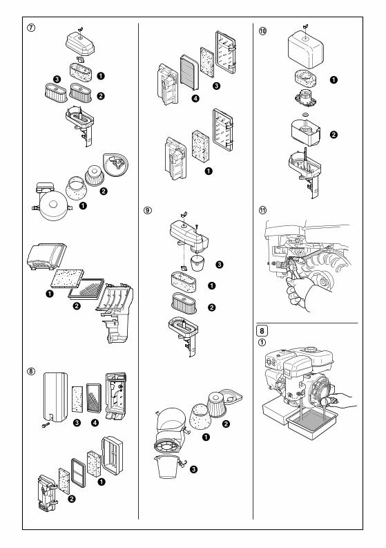
2. COMPONENTS(See Fig. 1)
SYMBOLS
NOTE Please refer to the illustrations on the back page of the front cover or back cover for Fig.1 to 8 indicated in the sentence.
❶ SPARK PLUG❷ EXHAUST OUTLET❸ MUFFLER COVER❹ AIR CLEANER❺ FUEL TANK❻ FUEL TANK CAP (FUEL FILLER)❼ SPEED CONTROL LEVER❽ RECOIL STARTER❾ STARTER HANDLE10 CHOKE LEVER
11 FUEL VALVE12 FUEL CUP13 CARBURETOR14 P.T.O. SHAFT15 OIL GAUGE (OIL FILLER)16 OIL DRAIN PLUG17 ENGINE SERIAL NO. (STAMPING)18 ENGINE NAME LABEL (SPEC. No.)19 STOP SWITCH20 OIL SENSOR UNIT
Add oil
Engine oil
On (Run) Engine start(Electric start)
Engine stop
Fast
Slow
Fuel shut-off
Fuel system failure / malfunction
Electrical preheat(Low tem-perature start aid)
Fuel (gasoline)
ChokeBattery
Fuel (diesel)Off (Stop)
Plus ;positive polarity
Minus ;negative polarity
Cold engine
Warm engine
Primer
Push primer
Do not push primer
Run position
Two times
Stop position
Stay clear of the hot surface.
Stop the engine before refueling.
Check for leakagefrom hose and fittings.
Shutt off fuel valvewhen the engine is not in use.
HOT, avoid touching the hot area.
Read manual.
Exhaust gas is poisonous.Do not operate in an unventilated room or enclosed area.
Fire, open flame and smoking prohibited.
D
EX13-40_en_EU7537.indd 4EX13-40_en_EU7537.indd 4 2013/11/24 21:26:012013/11/24 21:26:01

5
USENJP
FRDENLESITPTGRNOSEFIDKRUPLCNAR
3. PRE-OPERATION CHECKS
4. ELECTRIC STARTER MODELS
NOTEEngine shipped from our factory is without oil. Before starting engine, fi ll with oil. Do not over-fi ll.
1. CHECK ENGINE OIL (See Fig. 2)Before checking or refi lling engine oil, be sure the engine is located on stable, level surface and stopped.
■ Do not screw the oil gauge into the oil fi ller neck to check oil level. If the oil level is low, refi ll to the upper level with the following recommended oil.
■ Use 4-stroke automotive detergent oil of API service class SE or higher grade.
■ Select the viscosity based on the air temperature at the time of operation as shown in the table. (See Fig.2-①)
Oil capacity (Upper level) : (L)EX13/17/21 . . . . . . . . . . . . . . . . . . . . . 0.6EX27/30 . . . . . . . . . . . . . . . . . . . . . . . . 1.0EX35/40 . . . . . . . . . . . . . . . . . . . . . . . . 1.2
Explanation of Fig. 2-②❶ Oil Gauge ❷ Upper Level ❸ Lower Level ■ For the engine with Oil Bath type air cleaner, fi ll the engine oil upto the specifi ed level of the oil bath (oil pan).(See Fig.2-③-❶)
Oil capacity in the Oil Bath (oil pan) :EX13/17/21 . . . . . . . . . . . . . About 55 mL
2. CHECK FUEL (See Fig. 3)
WARNING ■Do not refuel while smoking, near an open fl ame or other such potential fi re hazards. Otherwise fi re accident may occur. ■Remove the statistic electricity from your body before refi lling the gasoline.Sparking from electrostatic discharge may cause the ignition to the vaporized fuel (gasoline) resulting burns.Static electricity can be discharged from the body by touching by hand the metal parts of the unit and the fuel dispensing pump. ■ Stop the engine and open the cap. ■ Use unleaded automotive gasoline only.
● Unleaded regular/premium or reformulated gasoline containing no more than 10% Ethanol (E10), or 15% MTBE may also be used.
● Never use gasoline containing ethanol exceeding 10%, or MTBE exceeding 15% because engine or fuel system damage could result.
● Never use stale or contaminated gasoline. ● Use of these non-recommended fuels may result in reduced performance and/or denial of warranty.
Fuel tank capacity : (L)EX13 . . . . . . . . 2.3 EX17 . . . . . . . .3.2EX21 . . . . . . . . 3.2 EX27 . . . . . . . .5.6EX35 . . . . . . . . 6.8 EX40 . . . . . . . .6.8
■ Close the fuel valve before fi lling the fuel tank.
For electric starter operation, proper electric wiring arrangements are needed before normal engine operation.
1. BATTERY ■ Use a battery rated 12V-24AH or larger.
WARNING ■Charge the battery in a fully ventilated location. ■Batteries generate hydrogen gas, which can be highly explosive. Do not smoke or allow fl ames or sparks near a battery, especially during charging. ■Be sure to confi rm Battery polarity. Connect positive (+) terminal fi rst when mounting battery, and disconnect negative (-) terminal fi rst when dismounting. ■Battery electrolyte contains sulphuric acid. Protect your eyes, skin and clothing. In case of contact, fl ush thoroughly with water and get prompt medical attention, especially if your eyes are affected.
2. BATTERY CABLE ■ Use a proper cable and ground wire to connect battery. ■ For GROUND WIRE, use a fl at braided wire of 20 sq. mm. or larger sectional area.
LA406 LA406
CABLE EARTH (GROUND) WIRE
25mm
6.5φ
7φ
6.5φ
Cable length Cable dia.
Wire gaugeAWG(BS)BWG
SAE JIS
Less than 1.5m 7.3 mm 1 6 AV15
1.5 m to 2.5 m 8.4 mm 0 4 AV20
2.5 m to 4 m 10.8 mm 3/0 2 AV30
Explanation of Fig. 3-①❶ Maximum Fuel level ■ Do not fi ll above the top of the fuel fi lter screen (marked ❶), or the fuel may overfl ow when it heats up later and expands.
■ When fi lling the fuel tank, always use the fuel fi lter screen. ■ Reattach the fuel cap by turning clockwise until reaching the physical stop (about one quarter turn). Do not attempt to turn past the physical stop or the fuel cap may be damaged.
■ Wipe off any spilled fuel before starting the engine.
EX13-40_en_EU7537.indd 5EX13-40_en_EU7537.indd 5 2013/11/24 21:26:022013/11/24 21:26:02

6
USENJP
FRDENLESIT
PTGRNOSEFI
DKRUPLCNAR
5. BELT PULLEY INSTALLATION ONTO KEYWAY-TYPE CRANKSHAFT
3. KEY SWITCH CABLEIf a remote key switch is used, select wires of proper gauge to connect it and magnetic switch of the engine.
Cable length Cable dia.
Wire gauge
AWG(BS) BWG JIS
Less than 1.5m 1.5 mm 14 16 AV1.25
1.5 m to 3 m 1.9 mm 12 14 AV2
3 m to 5 m 2.4 mm 10 13 AV3
4. WIRING
BATTERY
To KEY SWITCH(TERMINAL "ST")
CABLE
EARTH WIRE
MAGNETIC SWITCH
(1) Connect positive (+) terminal of the magnetic switch and positive (+) terminal of the battery with battery cable.
CAUTIONMake sure the polarity of battery terminals. Never connect the battery cable with the battery negative (-) terminal. When connecting the battery cable with the battery negative (-) terminal, diode rectifi er chips will be burned out or damaged in a moment.
(2) Ground negative terminal of the battery to the engine body or machine with ground wire.
(3) When installing the key switch on the machine, install with its drain hole at the bottom.
NOTETighten bolts and nuts on terminals securely so that they will not be loosened by vibration.
When installing the belt pulley and/or clutch onto keyway-type crankshaft (PTO shaft), proper and correct arrangements are needed.
The following illustration shows the correct installation of the applicable component parts.
Pulley
Bolt
Washer
PTO shaft
Key
5. WIRING DIAGRAM (RECOIL STARTER MODELS)
Spark plugBlack
Sto
p sw
itch
Ignition coil
Flywheel
To LED Lamp
Oil sensor
Oil sensorcontrol unit
WIRING DIAGRAM (ELECTRIC STARTER MODELS)
To Key switch (ST)
To Key switch (B)To Diode rectifierEX27
To Battery
LA108
LA408
Spark plugBlack
+M-M
STB
AC
LA106LA406LA306
Charge coil
Magneto
Electric starterMagnetic switch
Key switch
To LED Lamp
Oil sensor
Oil sensorcontrol unit
Battery
Dioderectifier
Ignition coil
Electric starter
Optional hardware shown by dotted lines.
EX13-40_en_EU7537.indd 6EX13-40_en_EU7537.indd 6 2013/11/24 21:26:022013/11/24 21:26:02

7
USENJP
FRDENLESITPTGRNOSEFIDKRUPLCNAR
■Metric keyway-type crankshaftWasher; Use the washer (material; SS41P) with the thickness
described below;
EX13/17/21 EX27 EX35/40Washer Thickness
mm4.5 or over 6.0 or over
ROBIN genuine part
020-00801-40,Washer
020-00800-20,Washer
020-01002-20,Washer
Thickness; mmOD; mmID; mmMaterial;
4.5288.5
SS41P
4.5358.5
SS41P
6.040
10.5SS41P
Bolt; Select the proper bolt and tighten it to the specifi ed tightening torque, as mentioned below;
EX13/17/21 EX27 EX35/40Effective thread length
mm16 to 22 18 to 27 18 to 27
Strength “8T” or higher
Tightening Torque
N•m(kgf•cm)
20 - 22(204 - 224)
40 - 50(408 - 510)
ROBIN genuine parts(Screw length; mm)
011-00802-50, Flange Bolt
25
011-01003-00,Flange Bolt
30
■ SAE (inch) keyway-type crankshaftWasher; Use the washer (material; SS41P) with the thickness
described below;
EX13/17/21 EX27 EX35/40Washer Thickness
in. (mm)
0.177 (4.5) or over
0.248 (6.3) or over
0.236 (6.0) or over
ROBIN genuine part
020-00801-40,Washer
(NA) (NA)
Thickness; mmOD; mmID; mmMaterial;
4.5288.5
SS41P
Bolt; Select the proper bolt and tighten it to the specifi ed tightening torque, as mentioned below;
EX13/17/21 EX27 EX35/40
Thread dimensions 5/16 - 24UNF2B 7/16 - 20UNF2B 3/8 - 24UNF2B
Effective thread length
in. (mm)
0.63 to 0.87(16 to 22)
0.71 to 1.06(18 to 27)
0.71 to 1.06(18 to 27)
Strength “8T” or higher “10T” or higher
Tightening TorqueN•m(kgf•cm)(ft•lb.)
20 - 22(204 - 224)(14.8 - 16.2)
50 - 60(510 - 612)(36.9 - 44.3)
45 - 55(457 - 561)(33.2 - 40.6)
(No ROBIN genuine part is available.)
Key LocationWhen using the belt pulley with the extended boss on both side as shown in the illustration, put the spacer so that the key stays in the keyway portion of the crankshaft.
Proper
Improper
Spacer
KeyClearance
Key should be with in this position.
Key
Belt Pulley InstallationInstall the belt pulley in the no over-hang condition as shown in the illustration.
CorrectPulley
Incorrect
Crankshaft (PTO)
Pulley
Crankshaft (PTO)
Large over-hang
EX13-40_en_EU7537.indd 7EX13-40_en_EU7537.indd 7 2013/11/24 21:26:022013/11/24 21:26:02
8
USENJP
FRDENLESIT
PTGRNOSEFI
DKRUPLCNAR
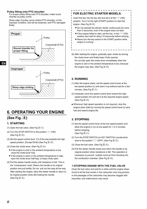
6. OPERATING YOUR ENGINE(See Fig. 4)1. STARTING(1) Open the fuel valve. (See Fig.4-①)
(2) Turn the STOP SWITCH to the position “ I ” (ON). (See Fig.4-②)
(3) Set the speed control lever 1/3 of the way towards the high speed position. (Except EX30) (See Fig.4-③)
(4) Close the choke lever. (See Fig.4-④) ■ If the engine is cold or the ambient temperature is low, close the choke lever fully.
■ If the engine is warm or the ambient temperature is high, open the choke lever half-way, or keep it fully open.
(5) Pull the starter handle slowly until resistance is felt. This is the “compression” point. Return the handle to its original position and pull swiftly. Do not pull out the rope all the way. After starting the engine, allow the starter handle to return to its original position while still holding the handle. (See Fig.4-⑤)
2. RUNNING(1) After the engine starts, set the speed control lever at the
low speed position (L) and warm it up without load for a few minutes. (See Fig.5-①)
(2) Gradually move the speed control lever toward the high speed position (H) and set it at the required engine speed. (See Fig.5-②)
■ Whenever high speed operation is not required, slow the engine down (idle) by moving the speed control lever to save fuel and extend engine life.
3. STOPPING(1) Set the speed control lever at the low speed position and
allow the engine to run at low speed for 1 or 2 minutes before stopping. (See Fig.6-①)
(2) Turn the STOP SWITCH (or KEY SWITCH) counterclock-wise to the position “○” (OFF). (See Fig.6-②)
(3) Close the fuel valve. (See Fig.6-③)
(4) Pull the starter handle slowly and return the handle to its original position when resistance is felt. This operation is necessary to prevent outside moist air from intruding into the combustion chamber. (See Fig.6-④)
※STOPPING ENGINE WITH THE FUEL VALVEClose the fuel valve and wait for a while until the engine stops. Avoid to let the fuel remain in the carburetor over long periods, or the passages of the carburetor may become clogged with impurities, and malfunctions may result.
(6) After starting the engine, gradually open choke by turning the choke lever and fi nally keep it fully opened. Do not fully open the choke lever immediately when the engine is cold or the ambient temperature is low, because the engine may stop. (See Fig.4-⑥)
FOR ELECTRIC STARTER MODELS.Insert the key into the key slot and set it at the “ I ” (ON) position. Turn it to the right (START position) to start the engine. (See Fig.4-⑤)
■ Do not operate the electric starter continuously for more than 5 secounds, even if the engine dose not start.
■ If the engine failed to start, set the key to the “ I ” (ON) position and wait for about 10 secounds before retrying.
■ Never turn the key switch to the START position while engine is running.
Pulley fi tting onto PTO shoulderFor proper pulley fi tting onto PTO shoulder, make round chamfer at pulley corner.Sharp edge of pulley corner strikes PTO shoulder. In this improper condition, bolt will be loosened, and PTO damaged fi nally.
Pulley
Crankshaft (PTO)
Pulley
Crankshaft (PTO)
Round chamfer for proper fitting
Sharp edge striking
Proper
Improper
EX13-40_en_EU7537.indd 8EX13-40_en_EU7537.indd 8 2013/11/24 21:26:022013/11/24 21:26:02

9
USENJP
FRDENLESITPTGRNOSEFIDKRUPLCNAR
7. MAINTENANCE(See Fig. 7)1. DAILY INSPECTION (See Fig. 7-①)Before running the engine, check the following service items.
❶ Loose or broken bolts and nuts❷ Clean air cleaner element❸ Enough clean engine oil❹ Leakage of gasoline and engine oil❺ Enough gasoline❻ Safe surroundings
❼ Excessive vibration, noise
2. PERIODIC INSPECTIONPeriodic maintenance is vital to the safe and effi cient operation of your engine. Check the table below for periodic maintenance intervals. Should the engine be operated in extremely dusty condition or in heavier loading condition, the maintenance intervals must be shortened depending on the contamination of oil, clogging of fi lter elements, wear of parts, and so on.
3. INSPECTING THE SPARK PLUG(See Fig. 7-②)
(1) Clean off carbon deposits on the spark plug electrode using a plug cleaner or wire brush.
(2) Check electrode gap. The gap should be 0.6 mm to 0.7mm. Adjust the gap, if necessary, by carefully bending the side electrode.
Recommended Spark Plug : E6RC (TORCH) or BR-6HS (NGK)
4. ENGINE OIL CHANGE (See Fig. 7-③,④)Initial oil change : After 20 hours of operationThereafter : Every 100 hours of operation
(1) When changing oil, stop the engine and loosen the drain plug. Drain the used oil while the engine is warm. Warm oil drains quickly and completely.
CAUTION
To prevent injury, pay attention to the hot oil.
(2) Re-install the drain plug before refi lling oil.
Oil capacity (Upper level) : (L)EX13/17/21 . . . . . . . . . . . . . . . . . . . . . 0.6EX27/30 . . . . . . . . . . . . . . . . . . . . . . . . 1.0EX35/40 . . . . . . . . . . . . . . . . . . . . . . . . 1.2
(3) Refer to page 5 for the recommended oil. ■ Always use the best grade and clean oil. Contaminated oil, poor quality oil and shortage of oil cause damage to engine or shorten the engine life.
Periodic Maintenance Schedule table
Maintenance ItemsEvery
8 hours(Daily)
Every 50 hours(Weekly)
Every 200 hours(Monthly)
Every 300
hours
Every 500
hours
Every 1000 hours
Clean engine and check bolts and nuts ● (Daily)
Check for leakage from hoses and fi tting ● (Daily)
Check and refi ll engine oil ● (Refi ll daily up to upper level)
Change engine oil ● (Initial 20 hours) ● (Every 100 hours)
Clean spark plug ● (Every 100 hours)
Clean air cleaner ●
Replace air cleaner element ●
Clean fuel cup ●
Clean and adjust spark plug and electrodes ●
Check and adjust valve clearance ●
Remove carbon from cylinder head ●
Clean and adjust carburetor ●
Replace fuel lines ●(Every 2 years)
Overhaul engine if necessary ●
EX13-40_en_EU7537.indd 9EX13-40_en_EU7537.indd 9 2013/11/24 21:26:032013/11/24 21:26:03

10
USENJP
FRDENLESIT
PTGRNOSEFI
DKRUPLCNAR
5. CLEANING FUEL CUP (See Fig. 7-⑤)
WARNING Flame Prohibited
WARNINGRemove the statistic electricity from your body before refi lling the gasoline.Sparking from electrostatic discharge may cause the ignition to the vaporized fuel (gasoline) resulting burns.Static electricity can be discharged from the body by touching by hand the metal parts of the unit.
(1) Inspect fuel cup for water and dirt. (See Fig. 7-⑤-❶)
(2) To remove water and dirt, close the fuel valve and remove the fuel cup.
(3) After removing dirt and water, wash the fuel cup with kerosene or gasoline. Reinstall securely to prevent leakage.
6. CLEANING AIR CLEANER (See Fig. 7-⑥ thru ⑩)
A dirty air cleaner element will cause starting diffi culty, power loss, engine malfunctions, and shorten engine life extremely.
Always keep the air cleaner element clean.
WARNING Flame Prohibited
A. Urethane Foam Element Type (See Fig.7-⑥)
Remove the element and wash it in washing oil (kerosene). Then saturate it in engine oil and squeeze it fi rmly before installing. (See Fig. 7-⑥-❶)
B. Dual Element Type (Urethane Foam and Paper elements) (See Fig.7-⑦) ■ For EX13/17/21 urethane foam, remove it from the paper element and wash it in washing oil (kerosene). Then saturate it in engine oil and squeeze it fi rmly before installing. (See Fig. 7-⑦-❶)
■ For EX27/35/40 urethane foam, remove it from the paper element and wash it thoroughly with detergent. Then dry it before installing. (See Fig. 7-⑦-❶)
■ For the paper element, clean by blowing on it with compressed air from the inside or tapping on it gently to remove dirt. Change the paper element when doing this fails to remove the dirt. (See Fig. 7-⑦-❷)
C. Dual Element Type (Urethane Foam and Nonwoven Cloth elements) (See Fig. 7-⑦) ■ For EX13/17/21 urethane foam, remove it from the non-woven cloth element and wash it thoroughly in washing oil (kerosene). Then saturate it in an oil mixture of 4 parts kerosene to 1 part engine oil and squeeze it fi rmly before installing. (See Fig. 7-⑦-❶)
■ For EX27 urethane foam, remove it from the non-woven cloth element and clean it via the method described in B above. (See Fig. 7-⑦-❶)
■ Wash the element in kerosene and drain off the kerosene. Then saturate it in a mixture of 4 parts kerosene and 1 part engine oil, wring the element to remove the mixture and install. (See Fig. 7-⑦-❸)
D. For Generator Type (See Fig. 7-⑧)
<Paper Element Specifi cations> (See Fig.7-⑧-❸,❹) ■ Wash the fi rst element (urethane foam) thoroughly with detergent. Then dry it before installing.(See Fig. 7-⑧-❸)
■ Clean the second element (paper element) by blowing on it with compressed air from the inside or tapping on it gently to remove dirt. Change the paper element when doing this fails to remove the dirt.(See Fig. 7-⑧-❹)
<Urethane Element Specifi cations>
EX13/17/21 (See Fig. 7-⑧-❶,❷) ■ Clean the fi rst element via the method described in A above. Remove the second element from its casing and wash it thoroughly with detergent. Then dry it before installing.
EX27/30 (See Fig. 7-⑧-❶) ■ Clean this via the method described in A above.
E. With Pre-cleaner Type (See Fig. 7-⑨)
Clean the elements (Fig.7-⑨-❶ and ❷) in the same way as described B Dual Element Type (Urethane Foam and Paper elements). Wash the dust pan of pre-cleaner (Fig. 7-⑨-❸) in water or kerosene and install it after drying.
F. Oil Bath Type (See Fig.7-⑩)
Clean the urethane foam (Fig.7-⑩-❶) in the same way as described A Urethane Foam Element Type.Drain the dirty oil from the oil pan (Fig.7-⑩-❷) and wash it in kerosene. Then fi ll the new engine oil upto the specifi ed oil level.
Oil capacity in the Oil Bath (oil pan) :
EX13/17/21 . . . . . . . . . . . . . About 55 mL
EX13-40_en_EU7537.indd 10EX13-40_en_EU7537.indd 10 2013/11/24 21:26:032013/11/24 21:26:03

11
USENJP
FRDENLESITPTGRNOSEFIDKRUPLCNAR
NOTEInstead of washing oil (kerosene), it is possible to wash the urethane foam element in a solution of mild detergent and warm water. Then rinse the element thoroughly in clean water. Allow the element to dry thoroughly. Soak the element in clean engine oil and squeeze out excess oil.
NOTEClean and replace air cleaner elements more often when operating in dusty environments. Replace the element in case that dirt or dust can not be removed and/or that the element is deformed or deteriorated.
7. FUEL HOSE REPLACEMENT (See Fig. 7-⑪)
WARNING ■ Take extreme caution when replacing fuel hose ; gasoline is extremely fl ammable. ■Remove the statistic electricity from your body before refi lling the gasoline.Sparking from electrostatic discharge may cause the ignition to the vaporized fuel (gasoline) resulting burns.Static electricity can be discharged from the body by touching by hand the metal parts of the unit.
Replace the fuel hose every 2 years. If fuel leaks from fuel hose, replace the fuel hose immediately.
8. CHECKING BOLTS, NUTS AND SCREWS ■ Retighten loose bolts and nuts. ■ Check for fuel and oil leaks.
■ Replace damaged parts with new ones.
9. CHECK BATTERY
WARNING Flame Prohibited
If the electrolyte fl uid is below level line, refi ll with distilled water to the upper level line.
8. PREPARATIONS FOR STORAGE
1. DISCHARGE FUEL (See Fig. 8-①)
WARNING Flame Prohibited
If you do not use the engine more than 1 month, discharge fuel to prevent gum in the fuel system and carburetor parts.
WARNING ■ Remove the statistic electricity from your body before refi lling the gasoline.Sparking from electrostatic discharge may cause the ignition to the vaporized fuel (gasoline) resulting burns.Static electricity can be discharged from the body by touching by hand the metal parts of the unit. ■ Always store/carry the fuel (gasoline) with metallic portable tank to prevent fi re.
■ Remove the fuel cup, place it over a container and open the fuel valve to discharge fuel from the fuel tank.
■ Remove the drain screw of the carburetor fl oat chamber and discharge fuel.
2. ENGINE OIL ■ Change the engine oil with fresh oil. ■ Remove the spark plug, pour about 5 cc of engine oil into the cylinder, slowly pull the starter handle of the recoil starter 2 or 3 times, and reinstall the spark plug.
3. CLEAN AND STORE ■ Slowly pull the recoil starter handle until resistance is felt and leave it in that position.
■ Clean the engine thoroughly with an oiled cloth, put the cover on, and store the engine indoors in a well ventilated, low humidity area.
4. BATTERY CHARGING
WARNING Flame Prohibited
■ The battery discharges itself even when not connected, therefore it is necessary to recharge it once a month.
EX13-40_en_EU7537.indd 11EX13-40_en_EU7537.indd 11 2013/11/24 21:26:032013/11/24 21:26:03

12
USENJP
FRDENLESIT
PTGRNOSEFI
DKRUPLCNAR
9. OIL SENSOR INSTRUCTIONS
1. FUNCTION OF OIL SENSORThe engine will stop automatically when the oil level falls below the safety limit. The engine cannot be started unless the level is raised above the prescribed limit. (See Fig.2-②)
2. RESTARTING(1) Fill the crankcase with oil up to the proper level.
(2) As for restarting and operating the engine, refer to section “6. OPERATING YOUR ENGINE” on page 8 .
■ Check the wire connector from the engine. It must be connected securely to the wire from oil sensor.
■ When selecting the engine oil, refer to page 5 for the recommended oil.
(OPTIONAL)10. EASY TROUBLESHOOTING
WHEN ENGINE WILL NOT START :Perform the following checks before you take the engine to your Robin dealer. If you still have trouble after completing the checks, take the engine to your nearest Robin dealer.
1. Is there a strong spark across the electrode ?
(1) Is the stop switch at position “ I ” (ON)?
(2) Remove and inspect the spark plug. If the electrode is fouled, clean or replace it with new one.
(3) Remove the spark plug and connect it to the plug cap. Pull the starter handle while grounding spark plug against engine body. Try with a new spark plug if the spark is weak or there is no spark. The ignition system is faulty if there is no spark with a new spark plug.
WARNING ■Wipe out spilled fuel carefully before testing. Place spark plug as far away from spark plug hole as possible. ■Do not hold spark plug by hand while pulling recoil starter.
NOTEThe engine with oil sensor will stop automatically when the oil level falls below the prescribed limit. Unless the oil level is raised above the prescribed limit, the engine will stop immediately after starting.
2. Is there enough compression? Pull the starter handle slowly and check if resistance is felt. If little force is required to pull the starter handle, check if the spark plug is tightened fi rmly. If the spark plug is loose, tighten it.
3. Is the spark plug wet with gasoline? (1) Is the fuel valve opened?
(2) Choke (close choke lever) and pull the starter handle fi ve or six times. Remove the plug and check if its electrode is wet. If the electrode is wet, fuel is well supplied to your engine.
(3) When the electrode is dry, check where the fuel stops. (Check the fuel intake of the carburetor.)
(4) In case the engine does not start with well supplied fuel, try using fresh fuel.
4. Is the battery well charged? If the battery for the electric starter is discharged, the engine will not start.
EX13-40_en_EU7537.indd 12EX13-40_en_EU7537.indd 12 2013/11/24 21:26:032013/11/24 21:26:03
13
USENJP
FRDENLESITPTGRNOSEFIDKRUPLCNAR
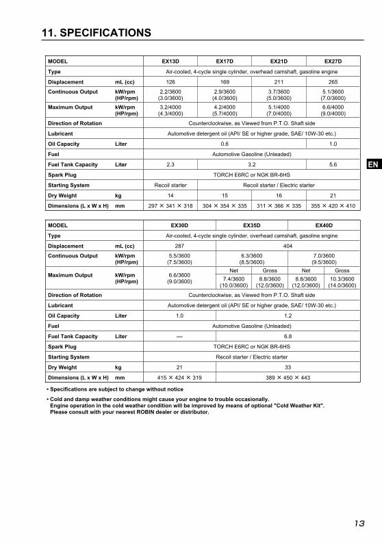
11. SPECIFICATIONS
MODEL EX13D EX17D EX21D EX27D
Type Air-cooled, 4-cycle single cylinder, overhead camshaft, gasoline engine
Displacement mL (cc) 126 169 211 265
Continuous Output kW/rpm(HP/rpm)
2.2/3600(3.0/3600)
2.9/3600(4.0/3600)
3.7/3600(5.0/3600)
5.1/3600(7.0/3600)
Maximum Output kW/rpm(HP/rpm)
3.2/4000(4.3/4000)
4.2/4000(5.7/4000)
5.1/4000(7.0/4000)
6.6/4000(9.0/4000)
Direction of Rotation Counterclockwise, as Viewed from P.T.O. Shaft side
Lubricant Automotive detergent oil (API/ SE or higher grade, SAE/ 10W-30 etc.)
Oil Capacity Liter 0.6 1.0
Fuel Automotive Gasoline (Unleaded)
Fuel Tank Capacity Liter 2.3 3.2 5.6
Spark Plug TORCH E6RC or NGK BR-6HS
Starting System Recoil starter Recoil starter / Electric starter
Dry Weight kg 14 15 16 21
Dimensions (L x W x H) mm 297 × 341 × 318 304 × 354 × 335 311 × 366 × 335 355 × 420 × 410
MODEL EX30D EX35D EX40D
Type Air-cooled, 4-cycle single cylinder, overhead camshaft, gasoline engine
Displacement mL (cc) 287 404
Continuous Output kW/rpm(HP/rpm)
5.5/3600(7.5/3600)
6.3/3600(8.5/3600)
7.0/3600(9.5/3600)
Maximum Output kW/rpm(HP/rpm)
6.6/3600(9.0/3600)
Net Gross Net Gross7.4/3600
(10.0/3600)8.8/3600
(12.0/3600)8.8/3600
(12.0/3600)10.3/3600
(14.0/3600)
Direction of Rotation Counterclockwise, as Viewed from P.T.O. Shaft side
Lubricant Automotive detergent oil (API/ SE or higher grade, SAE/ 10W-30 etc.)
Oil Capacity Liter 1.0 1.2
Fuel Automotive Gasoline (Unleaded)
Fuel Tank Capacity Liter - 6.8
Spark Plug TORCH E6RC or NGK BR-6HS
Starting System Recoil starter / Electric starter
Dry Weight kg 21 33
Dimensions (L x W x H) mm 415 × 424 × 319 389 × 450 × 443
• Specifi cations are subject to change without notice
• Cold and damp weather conditions might cause your engine to trouble occasionally.Engine operation in the cold weather condition will be improved by means of optional "Cold Weather Kit". Please consult with your nearest ROBIN dealer or distributor.
EX13-40_en_EU7537.indd 13EX13-40_en_EU7537.indd 13 2013/11/24 21:26:032013/11/24 21:26:03

[appendix]
Instructions for treatment as waste When disposing this product ,make sure that the fuel and oil should be drained from the engine ,and submit to local regulations.
[Annexe]
Instructions pour le traitement des déchets Quand ce produit doit être mis au rebut, s'assurer que le carburant et l’huile ont été vidangés correctement à partir du moteur, et que les règlements locaux sont bien observés.
[Anhang]
Anweisungen für die Behandlung als Abfall Bei der Entsorgung dieses Produkts sicherstellen, dass der Kraftstoff und das Öl aus dem Motor abgelassen wird und unter Befolgung aller örtlich gültigen Bestimmungen entsorgt wird.
[aanhangsel]
Instructies voor afvalverwerking Wanneer u dit product weggooit, moet u ervoor zorgen dat alle brandstof en olie uit de motor verwijderd is en dient u zich te houden aan de ter plaatse geldende regelgeving.
[anexo]
Instrucciones para el tratamiento de los residuos Cuando este producto debe ponerse al rechazo, asegurarse de que el combustible y el aceite se purgaron correctamente a partir del motor, y que se observan bien los reglamentos locales.
[appendix]
Istruzioni per lo smaltimentoPer lo smaltimento di questo prodotto, assicurarsi di aspirare il carburante e l'olio dal motore, in conformità con le regolamentazioni locali.
[apêndice]
Instruções para tratamento como resíduoQuando eliminar este produto, assegure-se de que o combustível e o óleo são escoados do motor e sujeitos às regulamentações locais.
[vedlegg]
Instruksjoner for behandling av avfall Når dette produktet kasseres, må man påse at drivstoffet og oljen tømmes fra motoren og behandles ifølge lokale renovasjonsforskrifter.
[appendix]
Anvisningar för avfallshanteringNär denna produkt ska kasseras, se då till att bränslet och oljan töms ur motorn, och att lokala bestämmelser efterföljs.
[LIITE]
Ohjeita jätteiden käsittelemisestä Hävittäessäsi tätä tuotetta muista, että polttoaine ja öljy täytyy tyhjentää moottorista. Muista myös noudattaa paikallisia säädöksiä.
[tillæg]
Anvisninger for behanling af affald Når du bortskaffer dette produkt, bedes du sikre dig, at motoren tømmes for brændstof og olie og afhændes i henhold til lokale regler.
EX series_illust.indd 02EX series_illust.indd 02 2013/11/28 2:44:252013/11/28 2:44:25

2ZZ9990220
PL
ISSUE EMD-EU7537
PRINTED IN JAPANNobember 2013
OHC Gasoline Engines
EX series
KR