Ex 2.07 GB - Servo Connectors · UNIEx·1 Index of contents PFLITSCH – the system partner The...
82
Ex 2.07 GB Ex cable glands
Transcript of Ex 2.07 GB - Servo Connectors · UNIEx·1 Index of contents PFLITSCH – the system partner The...

Ex 2.07 GB
Ex cable glands

UNI Ex · 1
Index of contents
PFLITSCH – the system partner
The enterprise
The Ex glands, standards
The UNI® Dicht system
The Ex range UNI Dicht
Ex-EMC range
Blueglobe Ex
Ex d
Accessories
Technical Annex
Fax enquiry form
Contact
Pages 2 - 3
Pages 4 - 11
Pages 12 - 13
Pages 14 - 41
Pages 42 - 53
Pages 54 - 59
Pages 60 - 64
Pages 65 - 67
Pages 68 - 76
Page 77
Page 79

2 · Ex
Over 85 years` experience and any
amount of system components with a
high utility value – this constitutes the
success story of PFLITSCH and their custo-
mers. More than 6,000 users from diffe-
rent branches of industry make use of our
cable glands and cable duct systems
today. 175 qualified and committed staff
and 12,000 system parts impressively
document PFLITSCH innovations from
over 8 decades.
The PFLITSCH UNI® Dicht system sets
criteria in cable and line installations: unit
construction constituting 7,000 high-
grade metal and plastic components
offers definitive individuality in series.
The user can make up his cable gland
specific to the application concerned indi-
vidually from this system. With theinnovative cable gland system blue-
globe, PFLITSCH is continuing to setfurther standards. For the spherical
sealing insert attains great clamping ran-
ges, higher densities and better strain
relief than conventional solutions.
The enterpriseCompetence in cable management

Ex · 3
This system thinking is also to be found in
PFLITSCH cable trunkings: The most
varied executions and cross sections,
accessory fittings and accessory compo-
nents are the prerequisites for individual
routing through buildings, plants and
machinery. Here the design engineer
makes his selection between the large
Industrial Trunking, the Mini Trunkingor the open basket tray. Planning soft-ware, tools and fastenings make indivi-
dual design and rational standard stock
products simple and reliable.
A company-wide quality management
system pursuant to DIN EN ISO 9001:2001 not only asks about product qualitybut also about customer satisfaction. The
insights thus gained flow directly into
further enhancement processes. It is
namely our corporate objective to realise
market-ready ideas all around safe cable
installations made of high-grade materi-
als in quality products.
Certification by recognised national and
international testing institutes such as
TÜV, VDE, PTB, GOST, UL and CSA as
well as approvals, for example, through
the automotive industry and railway engi-
neering specialists speak for themselves.
Our in-plant quality assurance guarantees
the perfect properties and condition of
our components.

4 · Ex
Since 2003, each new Ex appliance must
be certified in accordance with EU Direc-
tives – marked with the CE designation
and the special sign to prevent explosi-
ons. Since PFLITSCH began to have their
Ex cable glands in the UNI Dicht systemappropriately tested and certified as the
very first manufacturer in Europe, the
user today has at his disposal a wide
range of types, leaving nothing to be
desired.
PFLITSCH Ex cable glands conform with
EU Directives 94/9/EG (ATEX 95) for gases
(designation G) and dust (designation D).
These Ex glands may be used in all poten-
tially explosive areas of zones 1, 2, 21 and
22. PFLITSCH supply their UNI Dicht
cable glands both according to the metric
standard EN 60 423 as well as with the
well-known Pg connecting thread, with
standard and long thread. This ensures
that the user will always be able to order
just the right, fitting components with
new units and as replacements.
PFLITSCH Ex cable glandsMaximum safety in potentially explosive areas

Ex · 5
PFLITSCH cable glands come in galvani-
cally nickel-plated brass, corrosion-resi-stant stainless steel or in high-grade
PVDF plastic, and in each instance they
can be provided with different sealing
inserts for round and flat cables. There
are also types certified with UNI multiple
sealing inserts, enabling several cables to
be installed safely and space-savingly
through one cable gland.
Known as the innovative PFLITSCH soluti-
ons are Ex-certified EMC cable glands
with their continuous bonding of the line
screened braid. The UNI Dicht system pro-
ves its application orientation with pres-
sure screws for rigid and flexible line
laying with special strain relief and exten-
ded or reduced structural shapes.
By reason of the high requirements made
on the production and materials for explo-
sion-protected equipment, PFLITSCH
Ex-Types pass through special quality assu-
rance.
In this catalogue you will find all
PFLITSCH cable glands for the explosive
range as well as a summary of essential
information concerning the selection,
certification, standards and applications.

6 · Ex
Requirements made on explosion-protected cable and lineinstallations (explosion-protected cable glands)
All equipment, protective systems and components for use in
potentially explosive areas must comply with the EC Explosion
Protection Directive 94/9 EC, this also applying to explosion-pro-
tected cable glands as autonomous equipment.
This guideline is sometimes also termed “EC-Ex-Directive-ATEX
95” in the technical literature. The designation ATEX was duly
integrated into the numbering of EC design testing certificates,
issued on the basis of this EC directive, for differentiation. This
directive was included in national Federal German law through
the 11th Ordinance to the Equipment Safety Act/Explosion Pro-
tection Ordinance-ExVO.
The directive 94/9 EC regulates the requirements made on equip-
ment, protection systems and components for use in potentially
explosive areas. It contains the fundamental safety requirements
and encompasses the design, construction and also production
phase of explosion-protected equipment.
Explosion-protected equipment is subjected to special producti-
on monitoring, extending beyond standards ISO 9001 and the
following.
EC Explosion Protection Directive 94/9 EG regulates:
- product approval,
- the conformity procedure, comprising EC design testing,
quality control and the EC conformity declaration of the
manufacturer/supplier
- the CE conformity designation for equipment and protection
systems.
EC design testing is requisite for all equipment and protection
systems, implemented in potentially gas-explosive areas of zones
0, 1, 2 and those in potentially dust-explosive areas of zones 20
and 21. The manufacturer’s declaration is only adequate for
equipment and protection systems of category II D 3, implemen-
ted in zone 22.
EC design testing may only be carried out by the institutes
named (testing laboratories). The testing laboratories are listed
in the table below for explosion-protected, electrical equipment
(status: 11/2005).
Testing laboratories Country Ident-Nr. Full name
EXAM D 0158 BBG Prüf- und Zertifizier GmbH Fachstelle für elektrische Betriebsmittel – BVS, Bochum
PTB D 0102 Physikalisch-Technische Bundesanstalt, Braunschweig
TÜV-H D 0032 TÜV Hannover/ Sachsen-Anhalt e.V., Hannover
IBExU D 0637 Institut für Sicherheitsforschung GmbH, Freiberg (Sachsen)
Ineris F 0080 Institut National de L´Environnement industriel et des Risques, Verneuil
LCIE F 0081 Laboratoire Central des Industrie Électriques
KEMA NL 0344 Kema registered Quality BV, Arnhem
Nemko N 0470 Nemko AS; Oslo
EECS UK 0800 Electrical Equipment Certification Service, Buxton
Requirements made onexplosion-protected cable and line installations

Ex · 7
To enable an EC design testing certificate to be issued, the
manufacturer/supplier must present a certified quality assurance
system in accordance with ISO 9001 et sequ. for his production,
which is subjected to an additional QS audit with special requi-
rements made on potentially explosive equipment. The manu-
facturer/supplier will receive notification of the recognition of his
quality assurance for his production from the institute named.
PFLITSCH has EC design testing conducted by the PTB – Physical-
Technical Federal Institute and for special cable glands by
Nemko.
The PTB has recognised the QS system of PFLITSCH for the pro-
duction of explosion-protected cable glands under the number
PTB 01 ATEX Q 006.
EC directive 94/9 EG “ATEX” has been valid in Germany since
01.03.1996.
EC design testing certificates and EC conformity declarations of
the manufacturer/supplier must be available for all Ex cable
glands, Ex screw plugs and adapters.
The equipment or the packaging must be marked with the CE
symbol.
Cable and line entry points for equipment for applicationin explosion-endangered areas through gas and dust
Terminology:Cable glands are termed cable and line entry points in standardEN 60079-0.
Line and cable entry points (EN 60079-0)These are devices, enabling insertion of one or several electrical
and/or fibre-optic cables or lines into an electrical apparatus,
whereby the corresponding ignition protection class remains
maintained.
Ex line and cable entry points (EN 60079-0)These are line and cable entry points that are tested irrespective
of the enclosure of the apparatus, but are certified as apparatus
and which can be incorporated in the enclosure of the appara-
tus with installation.
Draining device (EN 60079-1)An integrated or detachable part of an enclosure, enabling water
formed by condensation to escape from the enclosure.
Breathing device (EN 60079-1)An integrated or detachable part of an enclosure, enabling the
exchange of the atmosphere inside the enclosure for the
ambient atmosphere.
Ex cable plug (EN 60079-1)
A closure unit provided with a thread, tested irrespective of the
apparatus enclosure, but certified as an apparatus and which can
be incorporated in the enclosure with installation without further
certification.

8 · Ex
Standards
To enable Ex cable glands and accessories to receive EC design
testing certification, they have to comply with certain standards
and are tested by the stated institutes accordingly.
These standards are for
Ex cable glands and accessories for use in explosive gasatmospheres:
EN 60079-0Electrical apparatus for explosive gas atmospheres
– Part 0: General requirements
EN 60079-1Electrical apparatus for explosive gas atmospheres
– Part 1: pressure-resistant casing “d”
EN 60079-7Electrical apparatus for explosive gas atmospheres
– Part 7: increased safety “e”
Ex cable glands and accessories for application inexplosive dust atmospheres:
EN 50281-1-1Electrical equipment for use in areas with combustible dust – Part
1-1: electrical apparatus with protection through enclosure –
construction and testing
EN 50014Electrical apparatus for potentially explosive areas –
General requirements
These two standards will be replaced in the course of 2006 by
the standards
EN 61241-0Electrical apparatus for use in areas with combustible dust – Part
0: General requirements
EN 61241-1Electrical apparatus for use in areas with combustible dust – Part
1: Protection through enclosure “tD”
The dust ignition protection class “Protection through enclosure
tD” is fulfilled through a high IP protection class according to EN
60529 and through limitation of the surface temperature of the
enclosure to a figure, at which a dust cloud or deposited dust
does not ignite or is not excited to glowing combustion. The
maximum admissible surface temperature is dependent on the
type of dust that may occur where used.
The enclosure protection class in accordance with EN 60529
must at least meet the conditions of IP protection class – dust-
protectedt IP 5X for application in zone 22.
With a standardised testing arrangement, the Ex cable glands in
this catalogue meet the conditions of IP protection class - dust-
proof IP 6X and are therefore suitable for use in zones 21 und 22
with conductive dust.
Protection class IP 6X is always to be tested on the enclosure to
be used with the cable gland mounted.
Standards and designations

Ex · 9
Designation of the Ex cable glands
Designation of the cable glands is structured as follows: e.g. Ex
cable gland U2. (U2. = Article Group)
II 2G/ D, Ex e II PTB 98 ATEX 3109, IP 68, thread type and
size, CE 102
Name / trademark names / trademark of the manufacturer
EU Community designations of explosion-protected apparatus
II apparatus group in accordance with
Ex-RL 94/9 EG,
2 apparatus category in accordance with
Ex-RL 94/9 EG
G/D for potentially explosive areas through gases,
vapours, mist (G) / dust (D)
Ex apparatus was built and tested according to
EN standards
e, d ignition protection classes – explosion-protec-
ted, pressure-resistant casing
II(A,B,C) explosion group with additional letters for
certain ignition protection classes
PTB, Nemko name of the institute stated, issuer of the
EC design test certificate
98 ATEX 3109 number of the EC design test certificate,
year – ATEX – serial number
X special references from the EC design test
certificate are to be observed
IP 68 IP protection class in accordance with
EN 60529
Type of thread M for metric, Pg for Pg connecting thread
Size thread size
CE CE designation for confirmation of compliance
with Ex-RL 94/9 EC
102 number of the institution, which carries out the
manufacturer`s Ex-QS audit, here, e.g.,
PTB see Listing Page 6.
Designation of small Ex cable glands is either done abbreviated
on the cable gland or completely on the smallest packaging unit.
Selection, installation, operation of electrical plants inpotentially explosive areas
For setting up and operating plants with potentially explosive
areas, EC directive 1999/92 EC „Minimum requirements for
improving the safety and health of workers potentially at risk
from explosive atmospheres“ is to be observed. This directive
has been realised in national law by the Industrial Safety Ordinan-
ce – BetrSichV. This ordinance is applicable to all plants requiring
monitoring in the sense of the Apparatus Safety Act.
The Industrial Safety Ordinance shall also apply to plants in
potentially explosive areas and to storage facilities, filler points,
fuelling stations and emptying points, in which highly, slightly,
inflammable liquids are stored or handled.
Electrical plants in potentially explosive areas must be mounted,
installed and operated in accordance with the regulations of this
ordinance as well as to state-of-the-art. They may only be put
ino operation, if they fulfill the requirements of the Industrial
Safety Ordinance.
In his capacity as employer, the plant operator has to carry out a
hazard assessment for his plants and to lay down same in an
explosion protection document. For assessment of the risk and
for determination of the explosion measures, explosion protecti-
on regulations EX-RL “Regulations for avoiding risks through
potentially explosive atmospheres with a compilation of exam-
ples” BGR 104 of BG Chemistry are also to be referred to.
Potentially explosive areas must be divided up into zones based
on the results of the assessment of endangerment (explosion
protection document).
Allocation of the zones for potentially explosive gas atmospheres
shall be carried out in accordance with EN 60079-10 (VDE 0165
Part 101). Allocation of the zones for potentially explosive dust
atmospheres shall be carried out in accordance with EN 50281-3
(VDE 0165 Part 102).

10 · Ex
Only equipment and protection systems may be used that comply
with the safety regulations of Ex – RL 94/9 EC.
Selection of the electrical equipment, installation and operations
shall be in accordance with the standards:
for potentially explosive gas atmospheres
EN 60079-14 (VDE 0165 Part 1)
for potentially explosive atmospheres through combustible dust
EN 50281-1-2 (VDE 0165 Part 2)
Selection of the equipment and protection systems of apparatus
group II equipment may only be used in those zones for which they
are suitable. The equipment must therefore comply at least with
the following categories subject to the operationally defined zones:
(see the following tables)
In the selection of the equipment and protection systems, the mini-
mum ignition temperatures and the operating figures of the gases,
vapours, mist and dust occurring in the zones must be taken into
due account. The surface temperatures of the equipment must lie
below the minimum ignition temperature with a safety margin.
These figures are a constituent of the explosion protection docu-
ment.
The sources of the parameters are:
for gases:Safety-engineering parameters of combustible liquids and gases
– explosion areas of gas mixtures, Wirtschaftsverlag NW
for dust:Combustible and explosion parameters of dust: ignition tempe-
rature, glowing temperature and conductibility of dust, BIA-
Report 12/97 (BIA-Institut für Arbeitssicherheit, St. Augustin).
Publisher HV-BG
Apart from EC directive 94/9 EC, which lays down the funda-
mental safety requirements, European standards (EN), in which
the requirements of the various ignition protection classes are
laid down, shall be applicable to the construction of the electri-
cal equipment (apparatus, protection systems and components)
for application in potentially explosive atmospheres. These stan-
dards shall be valid in all member states of the EU.
Potentially explosive Zone Appliance category Designation Ignition protectionatmosphere through at least classes
gases, vapours, mist min
Constantly, long-term or frequently 0 1 G II 1 G Ia appliances for zone 0
Occasionally 1 2 G II 2 G d, p, q, o, e, i, m
Rarely and briefly 2 3 G II 3 G n, nC, nP, nA, nL, nR,
Standards and designation
Potentially explosive Zone Appliance cat. Designation Enclosure protection Ignitionatmosphere through dust at least class EN 60529 protection classes
Constantly, long-term or frequently 20 1 D II 1 D IP 6X tD, maD, iaD,
Occasionally 21 2 D II 2 D IP 6X tD, pD, mD, iD,
Rarely and briefly
Conductive dust 22 2 D II 2 D IP 6X tD, pD, mD, iD,
Rarely and briefly
Non-conductive dust 3 D II 3 D IP 5X tD, pD, mD, iD,

Ex · 11
Equipment for potentially explosive atmospheres throughcombustible dust:
EN 50281-1-1Ignition protection class – protection by enclosure “tD”
Installation:
Apart from the Industrial Safety Ordinance and the already quo-
ted standards, further rules and regulations shall pertain to
assembly: VDE Regulations VDE 0100, VDE 0101, VDE 0800
BG Regulation BGR 132 “Avoidance of ignition hazards as a
result of electrostatic charging” (HV-BG)
The ignition protection class must not be changed by the moun-
ting of Ex cable glands and Ex sealing plugs on the equipment
enclosure. The temperature at the line entry point should not
exceed 70°C.
Ex cable glands of ignition protection class Ex d must be very
carefully installed, in as much as they lead directly into a termi-
nal connection chamber with ignition protection class Ex d. In
mounting, the special stipulations of standard EN 60079-14 and
the manufacturer`s assembly instructions are to be observed.
Assembly may only be carried out by personnel trained for explo-
sion protection.
Operation of electrical plants in potentially explosiveatmospheres
Ex-RL 1999/ 92 EC shall apply to the operation, control and
supervision of Ex installations, nationally in the Federal Republic
of Germany the Industrial Safety Ordinance. In addition, the
rules and regulations for normal electrical installations shall natu-
rally pertain as well, such as, for example:
Accident prevention regulations:
BGV A2 “Electrical plants and equipment”
EN 50110-1 (VDE 0105 Part 1) “Operation of electrical plants”
EN 50110-2 (VDE 0105 Part 2) “Operation of electrical plants,
national annexes”
Equipment for potentially explosive gas atmospheres:EN 60079-0
Part 0: General requirements
EN 50015Ignition protection class – oil casing “o”
EN 60079-2Ignition protection class – excess pressure casing – “p”
EN 50017Ignition protection class – sand casing – “q”
EN 60079-1Part 1: pressure-resistant casing – “d”
EN 60079-7Part 7: increased safety – “e”
EN 50020Ignition protection class – intrinsic safety “i”
EN 60079-18Ignition protection class – cast casing – “m”
EN 60079-26Special requirements made on equipment for Group II
Category 1G (zone 0)
EN 60079-15Part 15: Ignition protection class “n”

Material variants:
A
A
B
B
C
C
D
D
4
1 2
3
5
6
7
E
E
F
F
GG
Pressure screw (DS)
- brass
- stainless steel (1.4305)
- stainless steel (1.4571)
- PVDF
Sealing insert (E)
- TPE
- TPE-V
- silicone
Double nipple (DN)
- brass
- stainless steel (1.4305)
- stainless steel (1.4571)
- PVDF
O-ring
with metallic DN
- silicone (LSR)
Head thread
- extended
- reduced (on request)
Connecting thread
- Pg
- metric
- NPT
- standard/long
Cable
(standard = bold print)
The PFLITSCH UNI® Dicht systemComponents and assemblies
12 · Ex

Benefits: TPE sealing inserts / UNI colour code (CC)
1
2
3
5
6
7
4
- no standing water
- no putty needed
- IP 68 up to 10 bar to the cable and
pressure screw
- radial-symmetrically soft cable pressing
- large-surface strain relief
- no damage to the cable
- twisting protection through knurling on the
double nipple (DN) and sealing insert (E)
- no twisting of the cable with assembly/
disassembly
- IP 54 through diaphragms on the sealing
insert without tightening of the pressure
screw (DS)
- slotted O-ring secures sealing for enclosure
walling
We designate our quality:
12 grooves the PFLITSCH trademark
- Colour coding of the TPE sealing inserts (E),
thus direct allocation and verification of the
sealing inserts to the cable diameters used
®
yellow (ge)
grey (gu)
black (sw)
green (gr)
red (rt)
withe (ws)
blue (bl)
brown (br)
orange (or)
light yellow (hg)
anthracite (an)
light blue (hb)
pink (rs)
white (ws)
white (ws)
white (ws)
white (ws)
Colour codeCC
Sealing rangemax./min. diam.
Connecting thread
6,5 - 4
8 - 5
9,5 - 6,5
10,5 - 7
13 - 9
15,5 -11,5
18 -14
20,5 -17
25 -20
28 -24
32 -27
34 -29
36 -32
40 -36
44 -39
51 -45
56 -51
M12, M16, M20, M25
M16, M20, M25
M12, M16, M20, M25
M16, M20, M25
M20, M25, M32
M20, M25, M32, M40
M20, M25, M32, M40
M32, M40
M32, M40
M32, M40
M40, M50
M40, M50
M40, M50
M50
M63
M63
M63
Pg 7, Pg 9, Pg 11, Pg 13,5, Pg 16
Pg 9, Pg 11, Pg 13,5, Pg 16
Pg 9, Pg 11, Pg 13,5, Pg 16
Pg 11, Pg 13,5, Pg 16, Pg 21
Pg 13,5, Pg 16, Pg 21
Pg 16, Pg 21, Pg 29
Pg 21, Pg 29
Pg 21, Pg 29
Pg 29
Pg 29
Pg 36
Pg 36
Pg 36
Pg 42
Pg 48
Ex · 13

Fig. 1 Fig. 2
U59. Ex cable glandUNI Ex e II
PVDF, with metric thread EN 60 423.Colours: transparent, blue and blackProtection class EN 60 529: IP 68 up to 10 barArt. group: U59. Ex
Materials:
Gland: PVDF colours: transparent, blue or black
Sealing insert: TPE colour: UNI colour code (CC)
TPE-V colour: grey
LSR colour: transparent
Fig. 3
Lettering pressure screw M25
II 2G
/DExeII
PTB0
2ATEX111
5XIP68M25
01
02
Important pointer:
The maximum thermal load of the inserted lines and cables is to be observed. The gland isonly admissible for the connection of rigid-laid lines and cables. The operator must ensurecorresponding strain relief. The cable gland is to be mounted, so that it is protected againstmechanical damage (degree of the mechanical risk “low” – impact energy: 4 Joule – as perEN 60 079-1).
Visit us on the Internet:www.pflitsch.dei
The cable glandU 59. UNI Ex e IIis available for the most varied fields ofapplication in different executions ascomplete gland:
Temperature ranges of the cablegland as certified:M 16 -20 °C to +135 °CM 20 to M 50 -40 °C to +135 °C
With sealing inserts made of three mate-rials for different temperature ranges:
Temperature ranges of the sealinginserts as certified:TPE -40 °C to +115 °CTPE-V -40 °C to +135 °CLSR -40 °C to +135 °C
A gland comes complete in the variantswith simple, multiple and with closed sea-ling insert or with blind sealing inserts.
The Ex cable gland can be selected withtwo different connecting threads andconnecting thread lengths:
Connecting Connectingthread: thread length:
M-thread see Table Page 15EN 60 423 Type: U 59.N
M-thread see Table Page 16EN 60 423 Length 15 mm
Type: U 59.L
In two different forms:
Standard cable gland:U59.N, Form NStandard sealing range
Extended cable gland:U59.E, Form EExtended sealing range
Explosion protection:
Ignition protection class: gas explosion-protected – edust protection through enclosure – tD (A)
protection class EN 60 529: IP 68 to 10 barAppliance group/category: II 2 G/DApplicable in: zone 1, zone 2, zones 21 and 22 (conductive dust)Standards: EN 60 079-0 (EN 50 014)
EN 60 079-7 (EN 50 019)EN 50 281-1-1
EC design test certificate No.: PTB 02 ATEX 1115 X and supplementsDesignation: II 2 G/D, Ex e II PTB 02 ATEX 1115 X, IP 68
Type and size of thread, CE 0102
14 · Ex

U59. Ex cable glandUNI Ex e II
PVDF, with metric thread EN 60 423.Colours: transparent, blue and black,Protection class EN 60 529: IP 68 up to 10 barStandard execution: Form N,Art. Group: U59. N-Ex
Temperature range
-40 °C to +115 °C
-40 °C to +135 °C
-40 °C to +135 °C
Sealing inserts
Material
Standard: TPE
Variant: LSR
TPE-V
Colour
transparent
blue (RAL 5015)
black (RAL 9005)
Gland body
Material
PVDF
Article number Spanner-widthSW1 x E1/SW2 x E2
mm
CC*Sealing rangemax./min. ø
mm
Connectingthread/length
A D
21650y
21650y
22052y
22052y
22052y
22052y
22052y
22553y
22553y
22553y
22553y
22553y
22553y
23254y
23254y
23254y
23254y
23254y
24055y
24055y
24055y
24055y
24055y
25056y
25056y
25056y
7 ex
8 ex
7 ex
8 ex
9 ex
11 ex
13 ex
7 ex
8 ex
9 ex
11 ex
13 ex
16 ex
11 ex
13 ex
16 ex
18 ex
20 ex
16 ex
18 ex
20 ex
25 ex
28 ex
32 ex
34 ex
36 ex
M16x1,5***
M20x1,5
M25x1,5
M32x1,5
M40x1,5
M50x1,5
9
9
9
11
11,5
14
19x21
24x26,5
29x31,5/27x29,5
38x42/33x36,5
46x50/43x46
56x60,5/53x57
ge
gu
ge
gu
sw
gr
rt
ge
gu
sw
gr
rt
ws
gr
rt
ws
bl
br
ws
bl
br
or
hg
an
hb
rs
C
mm
21
22
23
27
30
34
50
50
50
25
10
5
6,5 - 4,0
8,0 - 5,0
6,5 - 4,0
8,0 - 5,0
9,5 - 6,5
10,5 - 7,0
13,0 - 9,0
6,5 - 4,0
8,0 - 5,0
9,5 - 6,5
10,5 - 7,0
13,0 - 9,0
15,5 - 11,5
10,5 - 7,0
13,0 - 9,0
15,5 - 11,5
18,0 - 14,0
20,5 - 17,0
15,5 - 11,5
18,0 - 14,0
20,5 - 17,0
25,0 - 20,0
28,0 - 24,0
32,0 - 27,0
34,0 - 29,0
36,0 - 32,0
* Colour code only with TPE ** sealing insert made of LSR unavailable *** (TPE-V) Temperature range M16: -20 °C to 135 °C
Please add appropriately forexecution desired
Order key
-
i
p
Order key
-
a
n
transp. = -blue = ablack = n
- = TPEi = LSRp = TPE-V
Order example:Ex cable gland U 59.,
M25x1,5 PVDF transp.,
complete gland with
TPE sealing insert
22553y 16 ex
M25x1,5 PVDF blue,
complete gland with
LSR sealing insert
22553y a i 16 ex
M25x1,5 PVDF black,
complete gland with
TPE-V sealing insert
22553y n p 16 ex
ATEX
Fig. 2
**
**
**
**
Fig. 1
SW2xE2
SW1xE1
CD
A
max.-min. ø
Ex · 15

U59. Ex cable glandUNI Ex e II
PVDF, with metric thread EN 60 423.Colours: transparent, blue and black,Protection class EN 60 529: IP 68 up to 10 bar,Connecting thread length: 15 mmArt. group: U59. L-Ex
Temperature range
-40 °C to +115 °C
-40 °C to +135 °C
-40 °C to +135 °C
Sealing inserts
Material
Standard: TPE
Variant: LSR
TPE-V
Colour
transparent
blue (RAL 5015)
black (RAL 9005)
Gland body
Material
PVDF
Article number Spanner-widthSW1 x E1/SW2 x E2
mm
CC*Sealing rangemax./min. ø
mm
Connectingthread/length
A D
82052y
82052y
82052y
82052y
82052y
82553y
82553y
82553y
82553y
82553y
82553y
83254y
83254y
83254y
83254y
83254y
84055y
84055y
84055y
84055y
84055y
85056y
85056y
85056y
7 ex
8 ex
9 ex
11 ex
13 ex
7 ex
8 ex
9 ex
11 ex
13 ex
16 ex
11 ex
13 ex
16 ex
18 ex
20 ex
16 ex
18 ex
20 ex
25 ex
28 ex
32 ex
34 ex
36 ex
M20x1,5
M25x1,5
M32x1,5
M40x1,5
M50x1,5
15
15
15
15
15
24x26,5
29x31,5/27x29,5
38x42/33x36,5
46x50/43x46
56x60,5/53x57
ge
gu
sw
gr
rt
ge
gu
sw
gr
rt
ws
gr
rt
ws
bl
br
ws
bl
br
or
hg
an
hb
rs
C
mm
22
23
27
30
34
50
50
25
10
5
6,5 - 4,0
8,0 - 5,0
9,5 - 6,5
10,5 - 7,0
13,0 - 9,0
6,5 - 4,0
8,0 - 5,0
9,5 - 6,5
10,5 - 7,0
13,0 - 9,0
15,5 - 11,5
10,5 - 7,0
13,0 - 9,0
15,5 - 11,5
18,0 - 14,0
20,5 - 17,0
15,5 - 11,5
18,0 - 14,0
20,5 - 17,0
25,0 - 20,0
28,0 - 24,0
32,0 - 27,0
34,0 - 29,0
36,0 - 32,0
* Colour code only with TPE ** sealing insert made of LSR unavailable
Please add appropriately forexecution desired
Order key
-
i
p
Order key
-
a
n
transp. = -blue = ablack = n
- = TPEi = LSRp = TPE-V
Order example:Ex cable gland U 59.L,
M25x1,5 PVDF, transp., 15 mm long,
complete gland with
TPE Sealing insert, 15,5 mm
82553y 16 ex
M25x1,5 PVDF blue, 15 mm long,
complete gland with
LSR Sealing insert, 15,5 mm
82553y a i 16 ex
M25x1,5 PVDF black,15 mm long,
complete gland with
TPE-V Sealing insert, 15,5 mm
82553y n p 16 ex
ATEX
**
**
Fig. 1
CD
A
max.-min. ø
SW2xE2
SW1xE1
Fig. 2
16 · Ex

U59. Ex cable glandUNI Ex e II
PVDF, with metric thread EN 60 423Colours: transparent, blue and black,Protection class EN 60 529: IP 68 up to 10 bar,Standard execution: Form E,Art group: U59. E-Ex
Temperature range
-40 °C to +115 °C
-40 °C to +135 °C
-40 °C to +135 °C
Sealing inserts
Material
Standard: TPE
Variant: LSR
TPE-V
Colour
transparent
blue (RAL 5015)
black (RAL 9005)
Gland body
Material
PVDF
Article number Spanner-widthSW1 x E1/SW2 x E2
mm
CC*Sealing rangemax./min. ø
mm
Connectingthread/length
A D
21651y
21652y
21652y
22053y
22054y
22054y
22554y
22554y
23255y
23255y
23255y
23255y
24056y
11 ex
11 ex
13 ex
16 ex
18 ex
20 ex
18 ex
20 ex
25 ex
28 ex
32 ex
34 ex
36 ex
M16x1,5
M20x1,5
M25x1,5
M32x1,5
M40x1,5
9
9
9
9
9
11
11,5
22x24,5
24x26,5
33x36,5/27x29,5
33x36,5
43x46
53x57
gr
gr
rt
ws
bl
br
bl
br
or
hg
an
hb
rs
C
mm
23
23
27
27
30
34
50
50
25
10
5
10,5 - 7,0
10,5 - 7,0
13,0 - 9,0
15,5 - 11,5
18,0 - 14,0
20,5 - 17,0
18,0 - 14,0
20,5 - 17,0
25,0 - 20,0
28,0 - 24,0
32,0 - 27,0
34,0 - 29,0
36,0 - 32,0
* Colour code only with TPE
Please add appropriately forexecution desired
Order key
-
i
p
Order key
-
a
n
transp. = -blue = ablack = n
- = TPEi = LSRp = TPE-V
Fig. 1 Fig. 2
Order example:Ex cable gland U 59. E,
M40x1,5, transparent, extended,
complete gland with
LSR sealing insert, 36,0 mm
24056y i 36 ex
ATEX
SWx E
CD
A
max.-min. ø
Fig. 3
Ex · 17

U59. Ex cable glandUNI Ex e II
PVDF, with metric thread EN 60 423,with multiple sealing insertsColours: transparent, blue and blackTechnical data see Page 14,Art group: U59. Ex
U55. Ex cable glandUNI Ex e II
PVDF, with Pg thread,with multiple sealing insertsColours: transparent, blue and blackArt. group: U 55. Ex
Available on request
Fig. 1
Materials:
Gland: PVDF Colourn: transparent, blue oder black
Sealing insert: TPE Colour: white
TPE-V Colour: grey
Important pointer:When multiple sealing inserts are used, all the openings must be assigned by lines or bybolts Art. group: U 7.3 (see Page 20). The bolt must fit the hole diameter in the sealinginsert.When Ex cable gland U 59. UNI Ex e is used with multiple sealing inserts in potentiallyexplosive atmospheres, the special conditions of the EC design test certificate are to beobserved: The maximum thermal load of the inserted lines and cables is to be observed.Only rigid-laid lines and cables may be inserted. The operator must ensure adequatestrain relief.
Visit us in Internet:www.pflitsch.dei
The UNI multiple sealing insert enables many lines to be installed in a confinedspace. The multiple sealing insert is to be selected according to the line diameter.
Protection class: IP 65, with a line diam. = hole diam. IP 68 up to 10 bar attainable.Reliable information can only be given once the protection class has been checked.
The sealing inserts are available in the most varied executions:• equal hole diameter• unequal hole diameter• blind holes – with partial assignment• as closed sealing insert – for self-drilling with unknown line diameters• as divided sealing insert
The multiple sealing inserts come in two materials:
Sealing insert Colour Temperature rangeTPE white -40 °C to +115 °CTPE-V grey -40 °C to +135 °C
18 · Ex

U59. Ex cable glandUNI Ex e II
PVDF, with metric thread EN 60 423,with multiple sealing insertsColours: transparent, blue and blackArt. group: U59. Ex
Temperature range
-40 °C to +115 °C
-40 °C to +135 °C
Sealing inserts
Material
Standard: TPE
Variant: TPE-V
Colour
transparent
blue (RAL 5015)
black (RAL 9005)
Gland body
Material
PVDF
Article number Spanner-widthSW1 x E1/SW2 x E2
mm
Line numberx home -ø
mm
Connectingthread/length
A D
22051y
22051y
22051y
22051y
22051y
22051y
22052y
22052y
22052y
22052y
22052y
22553y
22553y
22553y
22553y
22553y
23254y
23254y
23254y
23254y
23254y
23254y
23254y
23254y
23254y
23254y
23254y
23254y
23254y
m 2x4 ex
m 2x5 ex
m 2x6 ex
m 3x3 ex
m 3x4 ex
m 5x3,5 ex
m 2x5 ex
m 2x6 ex
m 3x4 ex
m 3x5,3 ex
m 4x3 ex
m 1x6/1x8 ex
m 2x4 ex
m 2x6 ex
m 4x6 ex
m 6x4 ex
m 1x8,5/1x12 ex
m 2x8 ex
m 2x9 ex
m 3x7 ex
m 3x9 ex
m 4x5 ex
m 4x6 ex
m 4x6,5 ex
m 4x8 ex
m 4x9 ex
m 6x4 ex
m 6x6,5 ex
m 8x4 ex
M 20x1,5
M 20 x1,5
M 25x1,5
M 32x1,5
9
9
9
11
24x26,5/22x24,5
24x26,5
29x31,5/27x29,5
38x42/33x36,5
C
mm
22
22
23
27
50
50
50
25
2x4
2x5
2x6
3x3
3x4
5x3,5
2x5
2x6
3x4
3x3,5
4x3
1x6/1x8
2x4
2x6
4x6
6x4
1x8,5/1x12
2x8
2x9
3x7
3x9
4x5
4x6
4x6,5
4x8
4x9
6x4
6x6,5
8x4
Please add appropriately forexecution desired
Order key
-
p
Order key
-
a
n
transp. = -blue = ablack = n
- = TPEp = TPE-V
Fig. 1 Fig. 2
Order example:Ex cable gland U 59.,
M20x1,5 PVDF, blue,
complete gland with
TPE sealing insert,
3 holes with ø 4mm
22052y a m 3x4 ex
ATEX
Fig. 3
SW2xE2
SW1xE1
CD
A
max.-min. ø
Ex · 19

20 · Ex
U59. Ex cable glandUNI Ex e II
PVDF, with metric thread EN 60 423,with multiple sealing insertsColours: transparent, blue and blackArt. group: U59. Ex
Temperature range
-40 °C to +115 °C
-40 °C to +135 °C
Sealing inserts
Material
Standard: TPE
Variant: TPE-V
Colour
transparent
blue (RAL 5015)
black (RAL 9005)
Gland body
Material
PVDF
Article number Spanner-widthSW1 x E1/SW2 x E2
mm
Line numberx home -ø
mm
Connectingthread/length
A D
24055y
24055y
24055y
24055y
24055y
24055y
24055y
24055y
24055y
24055y
24055y
25056y
25056y
25056y
m 1x6/1x8,5/1x10 ex
m 1x9/1x15 ex
m 2x11 ex
m 2x13 ex
m 4x9 ex
m 4x10 ex
m 5x9 ex
m 5x10 ex
m 6x6 ex
m 6x8 ex
m 7x7 ex
m 4x11,5 ex
m 4x13 ex
m 7x9 ex
M 40x1,5
M 50x1,5
11,5
14
46x50/43x46
56x60,5/53x57
C
mm
30
34
10
5
1x6/1x8,5/1x10
1x9/1x15
2x11
2x13
4x9
4x10
5x9
5x10
6x6
6x8
7x7
4x11,5
4x13
7x9
Please add appropriately forexecution desired
Order key
-
p
Order key
-
a
n
transp. = -blue = ablack = n
- = TPEp = TPE-V
Order example:Ex cable gland U 59.,
M40x1,5 PVDF, blue,
complete gland with
TPE-V sealing insert,
7 holes with ø 7mm
24055y a p m 7x7 ex
ATEX
Fig. 2
Fig. 1
U7.3 Sealing plugsColour: black, Temperature: -40 °C to +90 °C
Articlenumber
Ø
mm
BO 3,0x25
BO 4,0x20
BO 4,0x25
BO 5,0x25
BO 5,3x25
100
100
100
100
100
3
4
4
5
5,3
L
mm
25
20
25
25
25
Articlenumber
Ø
mm
L
mm
Articlenumber
Ø
mm
100
100
100
100
100
100
9
9,3
10
11
12
13
L
mm
20
20
20
20
25
25
Fig. 2
iNon-assigned holes must be assignedwith sealing plugs.
BO 6,0x25
BO 6,4x25
BO 7,0x25
BO 7,5x20
BO 8,0x20
6
6,4
7
7,5
8
25
25
25
20
20
100
100
100
100
100
BO 9,0x20
BO 9,3x20
BO 10x20
BO 11x20
BO 12x25
BO 13x25
Fig. 1

Ex · 21
U59. Ex cable glandUNI Ex e II
PVDF, with metric thread EN 60 423,with blind sealing insert,Colours: transparent, blue and blackArt. group: U59. Ex
Temperature range
-40 °C to +115 °C
Sealing inserts
Material
Standard: TPE, red
Colour
transparent
blue (RAL 5015)
black (RAL 9005)
Gland body
Material
PVDF
Article number Spanner-widthSW1 x E1/SW2 x E2
mm
Connectingthread/length
A D
22051y
22052y
22553y
23254y
24055y
25056y
151y
152y
153y
154y
155y
156y
ex B
ex B
ex B
ex B
ex B
ex B
ex B
ex B
ex B
ex B
ex B
ex B
M 20x1,5
M 20x1,5
M 25x1,5
M 32x1,5
M 40x1,5
M 50x1,5
Pg 11
Pg 13,5
Pg 16
Pg 21
Pg 29
Pg 36
9
9
9
11
11,5
14
9
9
9,5
11
11
13
24x26,5/22x24,5
24x26,5
29x31,5/27x29,5
38x42/33x36,5
46x50/43x46
56x60,5/53x57
22x24,5
24x26,5
27x29,5
33x36,5
43x46
53x56,3
C
mm
22
22
23
27
30
34
22
22
23
27
33
34
50
50
50
25
10
5
50
50
50
25
10
5
Please add appropriately forexecution desired
Order key
-
Order key
-
a
n
transp. = -blue = ablack = n
ATEX
Fig. 2
The blind sealing inserts are easily recognisable from outside from their conspicuous red colour and their shape.An advantage when explosion-protected plants are being inspected by the operator.
Fig. 1
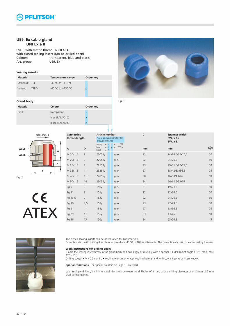
U59. Ex cable glandUNI Ex e II
PVDF, with metric thread EN 60 423,with closed sealing insert (can be drilled open)Colours: transparent, blue and black,Art. group: U59. Ex
Temperature range
-40 °C to +115 °C
-40 °C to +135 °C
Sealing inserts
Material
Standard: TPE
Variant: TPE-V
Colour
transparent
blue (RAL 5015)
black (RAL 9005)
Gland body
Material
PVDF
Article number Spanner-widthSW1 x E1/SW2 x E2
mm
Connectingthread/length
A D
22051y
22052y
22553y
23254y
24055y
25056y
150y
151y
152y
153y
154y
155y
156y
g ex
g ex
g ex
g ex
g ex
g ex
g ex
g ex
g ex
g ex
g ex
g ex
g ex
M 20x1,5
M 20x1,5
M 25x1,5
M 32x1,5
M 40x1,5
M 50x1,5
Pg 9
Pg 11
Pg 13,5
Pg 16
Pg 21
Pg 29
Pg 36
9
9
9
11
11,5
14
9
9
9
9,5
11
11
13
24x26,5/22x24,5
24x26,5
29x31,5/27x29,5
38x42/33x36,5
46x50/43x46
56x60,5/53x57
19x21,2
22x24,5
24x26,5
27x29,5
33x36,5
43x46
53x56,3
C
mm
22
22
23
27
30
34
21
22
22
23
27
33
34
50
50
50
25
10
5
50
50
50
50
25
10
5
Please add appropriately forexecution desired
Order key
-
p
Order key
-
a
n
transp. = -blue = ablack = n
Fig. 1
ATEX
Fig. 2
The closed sealing inserts can be drilled open for line insertion.Protection class with drilling (line diam. = hole diam.) IP 68 to 10 bar attainable. The protection class is to be checked by the user.
Work instructions for drilling open:Clamp the sealing insert firmly in the gland body and drill singly or multiply with a special TPE drill (point angle 118°, radial rake12° - 15°).Drilling speed: • V = 25 m/min; • cooling with air or water, cooling beforehand with coolant spray or in an icebox.
Special conditions: The special pointers on Page 18 are valid.
With multiple drilling, a minimum wall thickness between the drillholes of 1 mm, with a drilling diameter of > 10 mm of 2 mmshall be maintained.
- = TPEp = TPE-V
SW2xE2
SW1xE1
CD
A
max.-min. ø
22 · Ex

U59. Ex cable gland flat linesUNI Ex e II
PVDF, with metric thread EN 60 423,with sealing insert for flat lines,Colours: transparent, blue and black,Forms: g = rounded, v = oval, e = angular,Art. group: U59. Ex, protection class EN 60 529: IP 68
Colour
transparent
blue (RAL 5015)
black (RAL 9005)
Gland body
Material
PVDF
Order key
-
a
n
Fig. 1 Fig. 2
ATEX
Prerequisite:Prior to use of the Ex cable gland with flat sealing insert, the impermeability and strain relief of the cable gland mustbe tested in the PFLITSCH testing laboratory with a 1 meter long sample of the line to be used. Please contact us.
Special conditions:The maximum thermal load of the inserted lines and cables is to be observed.The gland is only approved for connection of rigidly-laid lines and cables.The operator must ensure adequate strain relief.The cable gland is to be mounted, so that it is protected against mechanical damage (the degree of mechanicalrisk “low“ – impact energy: 4 Joule – as per EN 60 079-1).
U 55. Ex cable glands with Pg connecting thread available on request.The same conditions shall pertain
50
50
25
10
5
Temperature range
-40 °C to +115 °C
-40 °C to +135 °C
Sealing inserts
Material
Standard: TPE
Variant: TPE-V
Colour
white
grey
Order key
-
p
Art.-No. – Form gPlease add appropriately forexecution desired
- = TPEp = TPE-V
Please add appropriately forexecution desired
- = TPEp = TPE-V
Please add appropriately forexecution desired
- = TPEp = TPE-V
220 51y f 2,8 g 10,5ex
220 51y f 3,5 g 9ex
220 51y f 4 g 6ex
225 53y f 5 g 12ex
225 53y f 5 g 16ex
225 53y f 7,5 g 14ex
232 54y f 5 g 17ex
232 54y f 7 g 18ex
232 54y f 9 g 15ex
240 55y f 6 g 29ex
240 55y f 8 g 25ex
240 55y f 10 g 25ex
240 55y f 13 g 28ex
250 56y f 6 g 30ex
250 56y f 6 g 36ex
250 56y f 8 g 36ex
250 56y f 11 g 34ex
250 56y f 12 g 35ex
Art.-No. – Form v
225 53y f 5 v 12ex
225 53y f 5 v 15ex
225 53y f 5,5 v 8,5ex
225 53y f 6 v 15ex
225 53y f 7 v 14ex
232 54y f 5 v 16ex
232 54y f 7 v 16,5ex
232 54y f 7 v 20ex
240 55y f 10 v 27ex
250 56y f 6,5 v 32ex
250 56y f 11 v 35ex
Art.-No. – Form e
225 53y f 8 e 12ex
232 54y f 4 e 15ex
240 55y f 6 e 26ex
240 55y f 7 e 26ex
250 56y f 5 e 36ex
250 56y f 8 e 30ex
transp. = -blue = ablack = n
transp. = -blue = ablack = n
transp. = -blue = ablack = n
Connectingthread/length
A D
M 20 x 1,5
M 25 x 1,5
M 32 x 1,5
M 40 x 1,5
M 50 x 1,5
9
9
11
11,5
14
Fig. 3 Form oval (v)
Fig. 4 Form rounded (g)
Fig. 5 Form angular (e)
Ex · 23

U55. Ex cable glandUNI Ex e II
PVDF, with Pg thread.Colours: transparent blue and blackProtection class EN 60 529: IP 68 up to 10 barArt. group: U55. Ex
Important pointer:
The maximum thermal load of the inserted lines and cables is to be observed. The gland isonly approved for connection of rigid-laid lines and cables. The operator must ensure ade-quate strain relief. The cable gland is to be mounted, so that it is protected against mecha-nical damage (the degree of mechanical risk “low“ – impact energy: 4 Joule – as perEN 60 079-1).
Visit us in Internet:www.pflitsch.dei
Cable glandU 55. UNI Ex e IIcomes as a complete gland for the mostvaried cases of application in differentexecutions.
With sealing inserts made of three mate-rials for different temperature ranges:
Temperature ranges of the sealinginserts as certified:TPE -40 °C to +115 °CTPE-V -40 °C to +135 °CLSR -40 °C to +135 °C
A gland is available complete in thevariants with simple, multiple and withclosed sealing insert, as well as with divi-ded sealing insert, or with blind sealinginserts.
The Ex cable gland can be selected withtwo different connecting threads andconnecting thread lengths:
Connecting Connecting threadthread: length:
Pg thread: see Table Page 25Type: U 55.N
Pg thread: see Table Page 26length 15 mmType: U 55.L
IIn three different forms:
Standard cable gland:U55.N, Form N
Extended cable gland:U55.E, Form E
Reduced cable gland:U55.R, Form R
Explosion protection:
Ignition protection class: gas explosion-protected – edust protection through enclosure – tD (A)
protection class EN 60 529: IP 68 to 10 bar
Equipment group/category: II 2 G/DApplicable in: zone 1, zone 2, zones 21 and 22 (conductive dust)Standards: EN 60 079-0 (EN 50 014)
EN 60 079-7 (EN 50 019)EN 50 281-1-1
EC design testcertificate No.: PTB 02 ATEX 1115 X and supplementsDesignation: II 2 G/D, Ex e II PTB 02 ATEX 1115 X, IP 68
Thread type and size, CE 0102
Materials:
Gland: PVDF Colours: transparent, blue oder black
Sealing insert: TPE Colour: UNI Farbcode (FC)
TPE-V Colour: grey
Fig. 1
24 · Ex

Temperature range
-40 °C to +115 °C
-40 °C to +135 °C
-40 °C to +135 °C
Sealing inserts
Material
Standard: TPE
Variant: LSR
TPE-V
Colour
transparent
blue (RAL 5015)
black (RAL 9005)
Gland body
Material
PVDF
Article number Spanner-widthSW x E
mm
CC*Sealing rangemax./min. ø
mm
Connectingthread/length
A D
150y
150y
151y
151y
151y
151y
152y
152y
152y
152y
152y
153y
153y
153y
153y
153y
153y
154y
154y
154y
154y
154y
155y
155y
155y
155y
155y
156y
156y
156y
7 ex
8 ex**
7 ex
8 ex**
9 ex
11 ex
7 ex
8 ex
9 ex
11 ex
13 ex
7 ex
8 ex**
9 ex
11 ex
13 ex
16 ex
11 ex**
13 ex
16 ex
18 ex
20 ex
16 ex
18 ex
20 ex
25 ex
28 ex
32 ex
34 ex
36 ex
Pg 9
Pg 11
Pg 13,5
Pg 16
Pg 21
Pg 29
Pg 36
9
9
9
9,5
11
11
13
19 x 21,2
22 x 24,5
24 x 26,5
27 x 29,5
33 x 36,5
43 x 46
53 x 56,3
ge
gu
ge
gu
sw
gr
ge
gu
sw
gr
rt
ge
gu
sw
gr
rt
ws
gr
rt
ws
bl
br
ws
bl
br
or
hg
an
hb
rs
C
mm
21
23
23
23
27
34
34
50
50
50
50
25
10
5
6,5 - 4,0
8,0 - 5,0
6,5 - 4,0
8,0 - 5,0
9,5 - 6,5
10,5 - 7,0
6,5 - 4,0
8,0 - 5,0
9,5 - 6,5
10,5 - 7,0
13,0 - 9,0
6,5 - 4,0
8,0 - 5,0
9,5 - 6,5
10,5 - 7,0
13,0 - 9,0
15,5 - 11,5
10,5 - 7,0
13,0 - 9,0
15,5 - 11,5
18,0 - 14,0
20,5 - 17,0
15,5 - 11,5
18,0 - 14,0
20,5 - 17,0
25,0 - 20,0
28,0 - 24,0
32,0 - 27,0
34,0 - 29,0
36,0 - 32,0
* Colour code only with TPE ** Sealing insert made of LSR unavailable
Please add appropriately forexecution desired
Order key
-
i
p
Order key
-
a
n
transp. = -blue = ablack = n
- = TPEi = LSRp = TPE-V
Order example:Ex cable gland U 55.,
Pg 16 PVDF transp.,
TPE sealing insert
153y 9 ex
Pg 16 PVDF blue,
LSR sealing insert
153y a i 9 ex
Pg 16 PVDF black,
TPE-V sealing insert
153y n p 9 ex
ATEX
Fig. 2
Fig. 1 Variants PVDF black and transparent, to the right with blind sealing insert
U55. Ex cable glandUNI Ex e II
PVDF, with Pg thread.Colours: transparent, blue and blackProtection class EN 60 529: IP 68 up to 10 barStandard execution: Form N
SWx E CD
A
max.-min. ø
Ex · 25

Temperature range
-40 °C to +115 °C
-40 °C to +135 °C
-40 °C to +135 °C
Sealing inserts
Material
Standard: TPE
Variant: LSR
TPE-V
Colour
transparent
blue (RAL 5015)
black (RAL 9005)
Gland body
Material
PVDF
Article number Spanner-widthSW x E
mm
CC*Sealing rangemax./min. ø
mm
Connectingthread/length
A D
180y
180y
181y
181y
181y
181y
182y
182y
182y
182y
182y
183y
183y
183y
183y
183y
183y
184y
184y
184y
184y
184y
185y
185y
185y
185y
185y
186y
186y
186y
Pg 9
Pg 11
Pg 13,5
Pg 16
Pg 21
Pg 29
Pg 36
15
15
15
15
15
15
15
19 x 21,2
22 x 24,5
24 x 26,5
27 x 29,5
33 x 36,5
43 x 46
53 x 56,3
ge
gu
ge
gu
sw
gr
ge
gu
sw
gr
rt
ge
gu
sw
gr
rt
ws
gr
rt
ws
bl
br
ws
bl
br
or
hg
an
hb
rs
C
mm
21
23
23
23
27
34
34
50
50
50
50
25
10
5
6,5 - 4,0
8,0 - 5,0
6,5 - 4,0
8,0 - 5,0
9,5 - 6,5
10,5 - 7,0
6,5 - 4,0
8,0 - 5,0
9,5 - 6,5
10,5 - 7,0
13,0 - 9,0
6,5 - 4,0
8,0 - 5,0
9,5 - 6,5
10,5 - 7,0
13,0 - 9,0
15,5 - 11,5
10,5 - 7,0
13,0 - 9,0
15,5 - 11,5
18,0 - 14,0
20,5 - 17,0
15,5 - 11,5
18,0 - 14,0
20,5 - 17,0
25,0 - 20,0
28,0 - 24,0
32,0 - 27,0
34,0 - 29,0
36,0 - 32,0
* Colour code only with TPE ** Sealing insert made of LSR unavailable
Please add appropriately forexecution desired
Order key
-
i
p
Order key
-
a
n
transp. = -blue = ablack = n
- = TPEi = LSRp = TPE-V
Order example:Ex cable gland U 55.L,
Pg 16 PVDF transp., 15 mm long,
TPE sealing insert
183y 9 ex
Pg 16 PVDF blue,
LSR sealing insert
183y a i 9 ex
Pg 16 PVDF black,
TPE-V sealing insert
183y n p 9 ex
ATEX
Fig. 1
U55. Ex cable glandUNI Ex e II
PVDF, with Pg threadColours: transparent, blue and black,Protection class EN 60 529: IP 68 up to 10 barConnecting thread length: 15 mmArt. group: U55. L
7 ex
8 ex**
7 ex
8 ex**
9 ex
11 ex
7 ex
8 ex
9 ex
11 ex
13 ex
7 ex
8 ex**
9 ex
11 ex
13 ex
16 ex
11 ex**
13 ex
16 ex
18 ex
20 ex
16 ex
18 ex
20 ex
25 ex
28 ex
32 ex
34 ex
36 ex
SWxE
CD
A
max.-min. ø
Fig. 2
26 · Ex

Temperature range
-40 °C to +115 °C
-40 °C to +135 °C
-40 °C to +135 °C
Sealing inserts
Material
Standard: TPE
Variant: LSR
TPE-V
Colour
transparent
blue (RAL 5015)
black (RAL 9005)
Gland body
Material
PVDF
Article number Spanner-widthSW x E
mm
CC*Sealing rangemax./min. ø
mm
Connectingthread/length
A D
15152y
15253y
15254y
15254y
15354y
15354y
15455y
15455y
15556y
15556y
15556y
13 ex
16 ex
18 ex
20 ex
18 ex
20 ex
25 ex
28 ex
32 ex
34 ex
36 ex
Pg 11
Pg 13,5
Pg 13,5
Pg 16
Pg 21
Pg 29
9
9
9
9,5
11
11
24x26,5
27x29,5
33x36,5
33x36,5
43x46
53x56,3
rt
ws
bl
br
bl
br
or
hg
an
hb
rs
C
mm
23
27
27
27
30
36
50
50
50
25
10
5
13,0 - 9,0
15,5 - 11,5
18,0 - 14,0
20,5 - 17,0
18,0 - 14,0
20,5 - 17,0
25,0 - 20,0
28,0 - 24,0
32,0 - 27,0
34,0 - 29,0
36,0 - 32,0
* Colour code only with TPE
Please add appropriately forexecution desired
Order key
-
i
p
Order key
-
a
n
transp. = -blue = ablack = n
- = TPEi = LSRp = TPE-V
Order example:Ex cable gland U 55.E,
Pg 21 PVDF transp., extended,
TPE-V sealing insert 25 mm
15455y p 25 ex
ATEX
Fig. 1
U55. Ex cable glandUNI Ex e II
PVDF, with Pg threadColours: transparent, blue and blackProtection class EN 60 529: IP 68 up to 10 barForm E, with extended sealing rangeArt. group: U55. E
U55. Ex reducing cable glandsavailable on request.
SW x E
CD
A
max.-min. ø
Fig. 2
Ex · 27

Fig. 2
Lettering pressure screw M25
II 2G/D
ExeII
PTB9
8ATEX310
9IP
68M25
01
02
U2. Ex cable glandsUNI Ex e II
Brass nickel-plated,with metric thread EN 60 423.Protection class EN 60 529: IP 68 up to 10 barArt. group: U2. Ex
Materials
Gland: brass, nickel-plated
Sealing inserts: TPE Colour: UNI colour code (CC)
TPE-VColour: natural
LSR Colour: transparent
Connecting thread-
sealing ring: Silicon LSR, Colour: red (-60 °C to +180 °C) Fig. 1
Important pointer:
The above mentioned gland with standard pressure screw is only approved for connectionof rigid-laid lines and cables. With flexibly laid lines, strain relief is to be ensured throughuse of the pressure screw with strain relief. The maximum thermal load of the insertedlines and cables is to be observed.
Visit us in theInternet: www.pflitsch.dei
Cable glandU2. UNI Ex e II is available for the mostvaried cases of application in differentexecutions. With sealing inserts made ofthree dissimilar materials for various tem-perature ranges as certified.
Temperature ranges of the sealinginserts:TPE -40 °C to +115 °CTPE-V -40 °C to +135 °CLSR -60 °C to +180 °C
A gland is available complete in thevariants with simple, multiple, closed,with blind, or dividedsealing inserts.
The Ex cable gland comes with three dif-ferent connecting threads and con-necting thread length:
Connecting Connecting threadthread: length:
M thread see Table Page 29EN 60 423 length 15 mm
Pg thread see Table Page 30length 15 mm
NPT on request
Likewise with two different pressurescrews:Standard pressure screw - for rigid-laidlines and cables.Pressure screw with strain relief – for fle-xible-laid lines.
Explosion protection:
Ignition protection class: gas explosive protected – edust protection through enclosure – tD (A)
protection class EN 60 529: IP 68 to 10 barEquipment group/category: II 2 G/DApplicable in: zone 1, zone 2, zones 21 and 22 (conductive dust)Standards: EN 60 079-0 (EN 50 014)
EN 60 079-7 (EN 50 019)EN 50 281-1-1
EC design test certificateNo.: PTB 98 ATEX 3109 and supplementsDesignation: II 2 G/D, Ex e II PTB 98 ATEX 3109, IP 68
Thread type and size, CE 0102
28 · Ex

U2. Ex cable glandUNI Ex e II
Brass nickel-plated, with metric thread EN 60 423.Protection class EN 60 529: IP 68 up to 10 barwith/without strain reliefArt. group: U2. M-Ex
Temperature range
-40 °C to +115 °C
-60 °C to +180 °C
-40 °C to +135 °C
Sealing inserts
Material
Standard: TPE
Variant: LSR
TPE-V
Pressure screw optionally with strain relief
Article number Spanner-widthSW1 x E1/SW2 x E2
mm
CC*Sealing rangemax./min. ø
mm
Connectingthread/length
A D
21049 d
21249 d
21650 d
21650 d
21650 d
22052 d
22052 d
22052 d
22052 d
22052 d
22553 d
22553 d
22553 d
22553 d
22553 d
22553 d
23254 d
23254 d
23254 d
23254 d
23254 d
24055 d
24055 d
24055 d
24055 d
24055 d
25056 d
25056 d
25056 d
25057 d
26358 d
M10x1
M12x1,5
M16x1,5
M20x1,5
M25x1,5
M32x1,5
M40x1,5
M50x1,5
M63x1,5
5
5
6
6,5
7,5
8
8
10
10
10
14x15,5
14x15,5
18x20/17x18,9
22x24,4
28x31,2/24x26,7
35x38,5/30x33,5
43x47,3/40x43,5
54x58/50x53,5
57x61
68x74/64x69
ge
ge
ge
gu
sw
ge
gu
sw
gr
rt
ge
gu
sw
gr
rt
ws
gr
rt
ws
bl
br
ws
bl
br
or
hg
an
hb
rs
ws
ws
C C2
mm mm
20 -
20 -
20 39
20 39
21 41
25 48
25 51
28 -
32 -
30 -
50
50
50
50
25
10
5
5
5
6,5 - 4,0
6,5 - 4,0
6,5 - 4,0
8,0 - 5,0
9,5 - 6,5
6,5 - 4,0
8,0 - 5,0
9,5 - 6,5
10,5 - 7,0
13,0 - 9,0
6,5 - 4,0
8,0 - 5,0
9,5 - 6,5
10,5 - 7,0
13,0 - 9,0
15,5 - 11,5
10,5 - 7,0
13,0 - 9,0
15,5 - 11,5
18,0 - 14,0
20,5 - 17,0
15,5 - 11,5
18,0 - 14,0
20,5 - 17,0
25,0 - 20,0
28,0 - 24,0
32,0 - 27,0
34,0 - 29,0
36,0 - 32,0
40,0 - 36,0
44,0 - 39,0
Please add appropriately forexecution desired
TPE = -LSR = iTPE-V = p
Strainrelief= zu
Order key
-
i
p
zu
7 ex
7 ex
7 ex
8 ex
9 ex
7 ex
8 ex
9 ex
11 ex
13 ex
7 ex
8 ex
9 ex
11 ex
13 ex
16 ex
11 ex
13 ex
16 ex
18 ex
20 ex
16 ex
18 ex
20 ex
25 ex
28 ex
32 ex
34 ex
36 ex
40 ex
44 ex
***
***
**
**
**
***
* Colour code only with TPE ** sealing insert made of LSR unavailable *** Strain relief not available
Fig. 2
Fig. 1
ATEX
Execution
nickel-plated
Gland body
Material
brass
Order key
d
Thread variant: standard dimension = Art. No. 22052d
15mm length = Art. No. 82052d
Fig. 3 Pressure screw with strain
relief for flexibly laid lines
Ex · 29

Article number Spanner-widthSW x E
mm
CC*Sealing rangemax./min. ø
mm
Connectingthread/length
A D
149 d
150 d
150 d
150 d
151 d
151 d
151 d
151 d
152 d
152 d
152 d
152 d
152 d
153 d
153 d
153 d
153 d
153 d
153 d
154 d
154 d
154 d
154 d
154 d
155 d
155 d
155 d
155 d
155 d
156 d
156 d
156 d
157 d
158 d
Pg 7
Pg 9
Pg 11
Pg 13,5
Pg 16
Pg 21
Pg 29
Pg 36
Pg 42
Pg 48
5
6
6
6,5
6,5
7
8
9
10
10
14 x 15,5
17 x 18,9
20 x 22,2
22 x 24,4
24 x 26,7
30 x 33,5
40 x 43,5
50 x 54
57 x 61
64 x 69
ge
ge
gu
sw
ge
gu
sw
gr
ge
gu
sw
gr
rt
ge
gu
sw
gr
rt
ws
gr
rt
ws
bl
br
ws
bl
br
or
hg
an
hb
rs
ws
ws
C
mm
20
20
20
21
21
25
27
28
30
30
50
50
50
50
50
25
10
5
2
2
6,5 - 4,0
6,5 - 4,0
8,0 - 5,0
9,0 - 6,5
6,5 - 4,0
8,0 - 5,0
9,5 - 6,5
10,5 - 7,0
6,5 - 4,0
8,0 - 5,0
9,5 - 6,5
10,5 - 7,0
13,0 - 9,0
6,5 - 4,0
8,0 - 5,0
9,5 - 6,5
10,5 - 7,0
13,0 - 9,0
15,5 - 11,5
10,5 - 7,0
13,0 - 9,0
15,5 - 11,5
18,0 - 14,0
20,5 - 17,0
15,5 - 11,5
18,0 - 14,0
20,5 - 17,0
25,0 - 20,0
28,0 - 24,0
32,0 - 27,0
34,0 - 29,0
36,0 - 32,0
40,0 - 36,0
44,0 - 39,0
Please add appropriately forexecution desired
TPE = -LSR = iTPE-V = p
7 ex
7 ex
8 ex
9 ex
7 ex
8 ex
9 ex
11 ex
7 ex
8 ex
9 ex
11 ex
13 ex
7 ex
8 ex
9 ex
11 ex
13 ex
16 ex
11 ex
13 ex
16 ex
18 ex
20 ex
16 ex
18 ex
20 ex
25 ex
28 ex
32 ex
34 ex
36 ex
40 ex
44 ex
**
**
**
**
Fig. 1 Variant for increased strain relief
Fig. 2
C2
mm
-
39
39
39
41
48
51
-
-
-
Fig. 3 Pressure screw with strain
relief for flexibly laid lines
Strainrelief= zu
* Colour code only with TPE ** sealing insert made of LSR unavailable *** Strain relief not available
***
***
ATEX
U2. Ex cable glandUNI Ex e II
Brass nickel-plated, with Pg threadProtection class EN 60 529: IP 68 up to 10 barwith/without strain reliefArt. group: U2. Pg-Ex
Temperature range
-40 °C to +115 °C
-60 °C to +180 °C
-40 °C to +135 °C
Sealing inserts
Material
Standard: TPE
Variant: LSR
TPE-V
Pressure screw optionally with strain relief
Order key
-
i
p
zu
Execution
nickel-plated
Gland body
Material
brass
Order key
d
Thread variants: Standard dimension D = Art. No. 150d
15mm length = Art. No. 180d
30 · Ex

***Complete article number on requestATEX
U2. Ex hose cable glandUNI Ex e II SVD
Brass nickel-platedwith metric or Pg connecting threadProtection class EN 60 529: IP 68 to 10 barArt. group: U2.
Temperature range
-40 °C to + 115 °C
-60 °C to + 180 °C
-40 °C to + 135 °C
Sealing inserts
Material
Standard: TPE
Variant: LSR
TPE-V
Execution
nickel-plated
Gland body
Material
brass
Article number Spanner-widthSW x E
mm
Sealing rangemax./min. ø
mm
***51d 1509 09ex
***51d 1509 07ex
***52d 1713 09ex
***53d 1811 11ex
***53d 1815 13ex
***54d 2316 16ex
***55d 3221 21ex
***56d 4030 28ex
6
6
6
6
6,5
7
7
8
20x22,2
20x22,2
22x24,4
24x26,7
24x26,7
30x33,5
40x43,5
50x54
C
mm
40
40
42
42
42
44
55
60
50
50
50
50
50
25
10
10
8,5 - 6,5
6,5 - 4,0
9,5 - 6,5
10,0 - 7,0
13,0 - 9,0
15,0 - 11,5
20,5 - 17,0
28,0 - 24,0
Hose A -ømax./min.
mm
15,0 - 13,0
15,0 - 13,0
17,0 - 13,0
18,0 - 15,0
18,0 - 15,0
23,0 - 19,0
32,0 - 28,0
40,0 - 34,0
Please add appropriately forexecution desired
TPE = -LSR = iTPE-V = p
Order key
-
i
p
I-ø
mm
9
9
13
11
15
16
21
30
NGTypS16.
Pg 9
Pg 11
Pg 11
Pg 11
Pg 13,5
Pg 21
Pg 21
Pg 29
Connectingthread/length
A D
Order key
d
10
10
13
13
13
16
23
31
***51d 1509 09ex
***51d 1509 07ex
***52d 1713 09ex
***53d 1811 11ex
***53d 1815 13ex
***54d 2316 16ex
***55d 3221 21ex
***56d 4030 28ex
6
6
6,5
6,5
6,5
7,5
8
9
20x22,2
20x22,2
22x24,4
24x26,7
24x26,7
30x33,5
40x43,5
50x54
40
40
42
42
42
44
55
60
50
50
50
50
50
25
10
10
8,5 - 6,5
6,5 - 4,0
9,5 - 6,5
10,0 - 7,0
13,0 - 9,0
15,0 - 11,5
20,5 - 17,0
28,0 - 24,0
15,0 - 13,0
15,0 - 13,0
17,0 - 13,0
18,0 - 15,0
18,0 - 15,0
23,0 - 19,0
32,0 - 28,0
40,0 - 34,0
9
9
13
11
15
16
21
30
M16
M20
M20
M20
M20
M25
M32
M40
10
10
13
13
13
16
23
31
Fig. 1 Fig. 2
Fig. 3
Electric hose gland for mounting of, e.g. spiralhoses with steel braiding and concurrent cablesealing/strain relief.
i
Nominal sizeNG
10
13
15
16
23
31
D1 x D2
mm
14,0x9,0
17,0x12,0
20,0x14,0
22,0x16,0
28,0x22,0
36,0x30,0
Art.-No.
GP 9
GP 11
GP 13
GP 16
GP 21
GP 29
Smm
2,5
2,5
3
3
3
3
R min.mm
40
60
70
70
90
140Fig. 5
50
50
50
50
50
25
Fig. 4
S16. Spiral hose with steel braidingColour: grey (RAL 7012), steel galvanisedMaterial: PVC/Buna with slightly undulated inner walland outside steel braiding for the heavy mech. loadProtection class: IP 68 to 10 barApplication: -20 °C to +70 °C
m
Ex · 31

U28. Ex cable glandsUNI Ex e II
Stainless steelwith metric thread EN 60 423Protection class EN 60 529: IP 68 up to 10 barArt. group: U28. Ex
Materials
Gland: stainless steel, bright VA - 1.4305 (VA - 1.4571 on request)
Sealing inserts: TPE Colour: UNI colour code (CC)
TPE-V Colour: grey
LSR Colour: transparent
Connecting thread-
sealing ring: Silicon LSR, Colour: red (-60 °C to +180 °C)
Important pointer:
Only rigidly laid lines and cables may be inserted. The operator must ensure correspondingstrain relief. The maximum thermal load of the inserted lines and cables is to be observed.
Visit us on theInternet: www.pflitsch.dei
Cable glandU28. UNI Ex e II is available for the mostvaried applications in different executi-ons. With sealing inserts made of threeDifferent materials for different tempera-ture ranges.
Temperature ranges of the sealinginserts as certified:TPE -40 °C to +115 °CTPE-V -40 °C to +135 °CLSR -60 °C to +180 °C
A gland is available complete in thevariants with simple, multiple, closed,with blind, or divided sealing inserts.
The Ex cable gland comes with three dif-ferent connecting threads and con-necting thread length:
Connecting Connectingthread: thread length:
M-thread see Table Page 33EN 60 423 length 15 mm
Pg on request
NPT on request
Explosion protection:
Ignition protection class: gas explosion protected – edust protection through enclosure – tD (A)
protection class EN 60 529: IP 68 to 10 barEquipment group/category: II 2 G/DApplicable in: zone 1, zone 2, zones 21 and 22 (conductive dust)Standards: EN 60 079-0 (EN 50 014)
EN 60 079-7 (EN 50 019)EN 50 281-1-1
EC design test certificateNo.: PTB 01 ATEX 3104 and supplementsDesignation: II 2 G/D, Ex e II PTB 01 ATEX 3104, IP 68
Thread type and size, CE 0102
Fig. 1
32 · Ex

U28. Ex cable glandUNI Ex e II
Stainless steel, with metric thread EN 60 423
Protection class EN 60 529: IP 68 up to 10 bar
Art. group: U28. M-Ex
Temperature range
-40 °C to +115 °C
-60 °C to +180 °C
-40 °C to +135 °C
Sealing inserts
Material
Standard: TPE
Variant: LSR
TPE-V
Article number Spanner-widthSW1 x E1/SW2 x E2
mm
CC*Sealing rangemax./min. ø
mm
Connectingthread/length
A D
21049 st
21249 st
21650 st
21650 st
21650 st
22051 st
22051 st
22052 st
22052 st
22052 st
22052 st
22052 st
22553 st
22553 st
22553 st
22553 st
22553 st
22553 st
23254 st
23254 st
23254 st
23254 st
23254 st
24055 st
24055 st
24055 st
24055 st
24055 st
25056 st
25056 st
25056 st
25057 st
26358 st
M10x1
M12x1,5
M16x1,5
M20x1,5
M25x1,5
M32x1,5
M40x1,5
M50x1,5
M63x1,5
5
5
6
6
6,5
6,5
7
8
9
10
10
14x15,5
14x15,5
19x21/17x18,9
22x24,4/20x22,2
22x22,4
27x30,4/24x26,7
36x39,6/30x33,5
46x51/41x45
55x60,5/50x54
60x65
68x74/65x70
ge
ge
ge
gu
sw
ge
gu
ge
gu
sw
gr
rt
ge
gu
sw
gr
rt
ws
gr
rt
ws
bl
br
ws
bl
br
or
hg
an
hb
rs
ws
ws
C
mm
20
20
20
20
20
21
25
25
28
30
30
50
50
50
50
25
10
5
5
5
6,5 - 4,0
6,5 - 4,0
6,5 - 4,0
8,0 - 5,0
9,5 - 6,5
6,5 - 4,0
8,0 - 5,0
6,5 - 4,0
8,0 - 5,0
9,5 - 6,5
10,5 - 7,0
13,0 - 9,0
6,5 - 4,0
8,0 - 5,0
9,5 - 6,5
10,5 - 7,0
13,0 - 9,0
15,5 - 11,5
10,5 - 7,0
13,0 - 9,0
15,5 - 11,5
18,0 - 14,0
20,5 - 17,0
15,5 - 11,5
18,0 - 14,0
20,5 - 17,0
25,0 - 20,0
28,0 - 24,0
32,0 - 27,0
34,0 - 29,0
36,0 - 32,0
40,0 - 36,0
44,0 - 39,0
Please add appropriately forexecution desired
TPE = -LSR = iTPE-V = p
Order key
-
i
p
7 ex
7 ex
7 ex
8 ex
9 ex
7 ex
8 ex
7 ex
8 ex
9 ex
11 ex
13 ex
7 ex
8 ex
9 ex
11 ex
13 ex
16 ex
11 ex
13 ex
16 ex
18 ex
20 ex
16 ex
18 ex
20 ex
25 ex
28 ex
32 ex
34 ex
36 ex
40 ex
44 ex
**
**
**
**
* Colour code only with TPE ** Sealing insert made of LSR unavailable
ATEX
Execution
1.4305
Gland body
Material
VA
Order key
st
Thread variant: standard dimension D = Art. No. 22553st
15mm length = Art. No. 82553st
Fig. 2
Fig. 3
Fig. 1
Ex · 33

The impermeability, retention force and strain relief are to be tested irrespective of thecable used or the user. Corresponding tests can also be carried out in the PFLITSCHtesting laboratory by arrangement.i
U2. und U28. Ex cable glandUNI Ex e II, with multiple sealing inserts
U2. M UNI Dicht Ex e II - brass, nickel.platedU28. M UNI Dicht Ex e II – stainless steel, brightwith normal or 15 mm long connecting thread lengthProtection class EN 60 529: IP 65
U2. und U28. Ex cable glandUNI Ex e II, with multiple sealing inserts
with Pg thread,Art. group: U 2. Ex, U28. Ex
Available on request
Fig. 1
Materials:
Gland: U2. M-Ex brass, nickel-plated
U28. M-Ex stainless steel 1.4305
Sealing insert: TPE Colour: white
TPE-V Colour: grey
Important pointer:When using Ex cable glands UNI Dicht Ex e II with multiple sealing inserts in potentiallyexplosive atmospheres, the special conditions of the EC design test certificate are to beobserved:For application in potentially explosive atmospheres, a minimum wall thickness of 1 mm,with a hole diam. of >10mm of 2mm must be kept to.When using the multiple sealing inserts, all the openings must be assigned by lines orbolts Art. group: U 7.3 (see Page 20). The bolt must fit the hole diameter in the sealinginsert. The maximum thermal load of the inserted lines and cables must be observed.Only ridily laid lines and cables may be inserted. The operator must ensure correspon-ding strain relief.
The multiple sealing inserts make for the installation of many lines in a confined space.They come for the varied gland sizes with a varying number of holes and hole diame-ters. For use in potentially explosive atmospheres, a minimum wall thickness of 1 mmmust be kept to; compared to regular application the possibilities are thus somewhatlimited.
Protection class EN 60529:IP 65, with line diam. = hole diam.IP 68, to 10 bar is also attainable.Reliable information can only be given once the protection class has been checked.
When used in the potentially explosive atmospheres of zones 21 and 22, with theoccurrence of conductive dust, protection class IP 6X must be reached.Testing the IP protection class of the planned application (cable gland and the linesused) can be carried out by the Pflitsch testing laboratory by arrangement.
34 · Ex

Temperature range
-40 °C to +115 °C
-40 °C to +135 °C
Sealing inserts
Material
Standard: TPE
Variant: TPE-V
Colour
white
grey
Material
brass, nickel-plated
VA 1.4305
Gland body
Art. group
U2. M-Ex
U28. M-Ex
Article number Line numberxHole-ø
mm
21049 m 1x4 ex
21650 m 1x4 ex
21650 m 2x3 ex
21650 m 2x4 ex
22051 m 1x4 ex
22051 m 2x3 ex
22051 m 2x4 ex
22051 m 2x5 ex
22051 m 2x6 ex
22051 m 3x4 ex
22052 m 2x6 ex
22052 m 3x4 ex
22052 m 3x5,3 ex
22553 m 2x4 ex
22553 m 2x6 ex
22553 m 2x8 ex
22553 m 3x7 ex
22553 m 4x4 ex
22553 m 4x6 ex
23254 m 2x8 ex
23254 m 2x9 ex
23254 m 3x7 ex
23254 m 3x9 ex
23254 m 4x5 ex
23254 m 4x6 ex
23254 m 4x8 ex
24055 m 2x11 ex
24055 m 2x13 ex
24055 m 3x11 ex
24055 m 4x9 ex
25056 m 2x15 ex
25056 m 3x10 ex
25056 m 4x11,5 ex
M10x1
M16x1,5
M20x1,5
M20x1,5
M25x1,5
M32x1,5
M40x1,5
M50x1,5
1x4
1x4
2x3
2x4
1x4
2x3
2x4
2x5
2x6
3x4
2x6
3x4
3x5,3
2x4
2x6
2x8
3x7
4x4
4x6
2x8
2x9
3x7
3x9
4x5
4x6
4x8
2x11
2x13
3x11
4x9
2x15
3x10
4x11,5
50
50
50
50
50
25
10
5
Please add appropriately forexecution desired
Order key
-
p
Order key
d
st
brass = dVA = st
- = TPEp = TPE-V
Order example:Ex cable gland U 28.,
M20x1,5, VA 1.4305,
TPE-V sealing insert
22051 st p m2x5 ex
Fig. 2
Fig. 1
U2. and U28. Ex cable glandUNI Ex e II, with multiple sealing inserts
U2. M UNI Dicht Ex e II - brass, nickel.platedU28. M UNI Dicht Ex e II – stainless steel, brightwith normal or 15 mm long connecting thread lengthProtection class EN 60 529: IP 65
U2. / U28. Ex cable glands with Pg connectingthread available on request.
Thread variant: standard = Art. No 21049
15mm length = Art. No.81049
Connectingthread/length
A D
5
6
6
6,5
6,5
7
8
9
ATEX
Ex · 35

36 · Ex
Ex cable gland with blind or closed sea-ling inserts used to seal non-assigned drillholes in enclosures of ignition protectionclass Ex “e”. They subsequently offer thepossibility of inserting a line or cable intothe enclosure by simply exchanging theblind/closed sealing insert for a standardsealing insert. An Ex sealing plug is thusno longer necessary.
The sealing inserts are available in twodifferent materials:
Standard: TPE – red, white-40 °C to +115 °C
Variant: TPE-V – grey on request-40 °C to +135 °C
Ex cable glands with blind or closedsealing insert have the advantages:
• gland body already available• high protection class IP 68• blind sealing insert is easily exchangedfor the fitting sealing insert
• they are easy to recognise through thered colour (only TPE)
• rational preassembly• the enclosure inside is to be protectedfrom dirt during the constructionphase
• no Ex sealing plug necessary
All the Ex cable glands with an EC designtest certrificate in accordance with ATEXdirective have been tested as completeglands also with blind sealing insert orwith closed sealing insert.
The blind sealing inserts are easily recog-nisable in appearance through their con-spicuous red colour (only TPE) and theirshape – an enormous benefit during theinspection of explosion-protected installa-tions by the operator.
The closed sealing inserts can be drilledopen for line insertion. Protection classfor drilling open (line diam. = hole diam.)IP 68 to 10 bar attainable. The protectionclass is to be checked by the user.
Work instructions for drilling:The sealing insert is to be firmly prestrained in the gland body and drilled once or several time with a TPE drill (point angle118°, tool siderake 12° to 15°).Drilling speed V = 25m/min; cool with air or water, beforehand cool with coolant spray or in an icebox.
Special conditionsThe important pointers on Page 34 are valid. When drilling several times, the minimum wall thickness between the drill holes of 1mm,with a borehole diam. > 10 mm of 2 mm is to be kept to.
Visit us on theInternet: www.pflitsch.dei
Ex cable glandsUNI Dicht Ex e IIwith blind sealing inserts,with closed sealing inserts
Fig. 1 Fig. 2

Ex · 37
Temperature range
-40 °C to +115 °C
-40 °C to +135 °C
Sealing inserts
Material
Standard: TPE
Variant: TPE-V
Colour
red
grey
Material
brass, nickel-plated
VA 1.4305
Gland body
Art. group
U2. Ex
U28. Ex
Article number
21049 ex B
21249 ex B
21650 ex B
22052 ex B
22553 ex B
23254 ex B
24055 ex B
25056 ex B
26358 ex B
149 ex B
150 ex B
151 ex B
152 ex B
153 ex B
154 ex B
155 ex B
156 ex B
50
50
50
50
50
25
10
5
5
50
50
50
50
50
25
10
5
Please add appropriately forexecution desired
Order key
-
p
Order key
d
st
brass = dVA = st
- = TPEp = TPE-V
Fig. 1
U2. und U28. Ex cable glandUNI Ex e II, with blind sealing inserts
U2. UNI Dicht Ex e II - brass, nickel-platedU28. UNI Dicht Ex e II – stainless steel, brightProtection class EN 60 529: IP 68 to 10 barMetric or Pg threadWith standard connecting thread length
Spanner-widthSW1 x E1/SW2 x E2
mm
14x15,5
14x15,5
18x20/17x18,9
22x24,4
28x31,2/24x26,7
35x38,5/30x33,5
43x47,3/40x43,5
54x58/50x54
68x74/64x69
14x15,5
17x18,9
20x22,2
22x24,4
24x26,7
30x33,5
40x43,5
50x64
C
mm
20
20
20
21
21
25
27
28
30
20
20
20
21
21
25
27
28
Connectingthread/length
A D
M10x1
M12x1,5
M16x1,5
M20x1,5
M25x1,5
M32x1,5
M40x1,5
M50x1,5
M63x1,5
Pg 7
Pg 9
Pg 11
Pg 13,5
Pg 16
Pg 21
Pg 29
Pg 36
5
5
6
6,5
6,5
7
8
9
10
5
6
6
6,5
7
7
8
9
ATEX

38 · Ex
Temperature range
-40 °C to +115 °C
-40 °C to +135 °C
Sealing inserts
Material
Standard: TPE
Variant: TPE-V
Colour
white
grey
Material
brass, nickel-plated
VA 1.4305
Gland body
Art.-group
U2. Ex
U28. Ex
Article number
21049 g ex
21249 g ex
21650 g ex
22052 g ex
22553 g ex
23254 g ex
24055 g ex
25056 g ex
26358 g ex
149 g ex
150 g ex
151 g ex
152 g ex
153 g ex
154 g ex
155 g ex
156 g ex
157 g ex
158 g ex
50
50
50
50
50
25
10
5
5
50
50
50
50
50
25
10
5
5
5
Please add appropriately forexecution desired
Order key
-
p
Order key
d
st
brass = dVA = st
- = TPEp = TPE-V
Fig. 2
Fig. 1
U2. und U28. Ex cable glandUNI Ex e II, with closed sealing inserts
U2. UNI Dicht Ex e II - brass, nickel-platedU28. UNI Dicht Ex e II – stainless steel, brightProtection class EN 60 529: IP 68 up to 10 barMetric or Pg threadwith standard connecting thread length
Spanner-widthSW1 x E1/SW2 x E2
mm
14x15,5
14x15,5
18x20/17x18,9
22x24,4
28x31,2/24x26,7
35x38,5/30x33,5
43x47,3/40x43,5
54x58/50x54
68x74/64x69
14x15,5
17x18,9
20x22,2
22x24,4
24x26,7
30x33,5
40x43,5
50x54
57x61
64x69
C
mm
20
20
20
21
21
25
27
28
30
20
20
20
21
21
25
27
28
30
30
Connectingthread/length
A D
M10x1
M12x1,5
M16x1,5
M20x1,5
M25x1,5
M32x1,5
M40x1,5
M50x1,5
M63x1,5
Pg 7
Pg 9
Pg 11
Pg 13,5
Pg 16
Pg 21
Pg 29
Pg 36
Pg 42
Pg 48
5
5
6
6,5
7,5
8
8
10
10
5
5
6
6,5
6,5
7
8
9
10
10
ATEX

Ex · 39
Connectingthread
A
M 20 x 1,5
M 25 x 1,5
M 32 x 1,5
M 40 x 1,5
M 50 x 1,5
50
50
25
10
5
Prerequisite:Prior to use of the Ex cable gland with flat sealing insert, the impermeability and strain relief of the cable gland mustbe tested in the PFLITSCH testing laboratory with a 1 meter long sample of the line to be used.Please contact us.
Special conditions:The maximum thermal load of the inserted lines and cables is to be observed.The gland is only approved for connection of rigidly laid lines and cables.The operator must ensure adequate strain relief.The cable gland is to be mounted, so that it is protected against mechanical damage (the degree of mechanical risk“low” – impact energy: 4 Joule – as per EN 60 079-1).
U2./U28 Ex cable glands with Pg connecting thread available on request.
Temperature range
-40 °C to +115 °C
-40 °C to +135 °C
Sealing inserts
Material
Standard: TPE
Variant: TPE-V
Colour
white
grey
Material
brass, nickel-plated
VA 1.4305
Gland body
Art. group
U2. M-Ex
U28. M-Ex
Order key
-
p
Order key
d
st
Fig. 1
U2. und U28. Ex cable glandUNI Ex e II, for flat lines
U2. UNI Dicht Ex e II - brass, nickel-platedU28. UNI Dicht Ex e II – stainless steel, brightMetric or Pg threadwith standard connecting thread lengthwith sealing insert for flat lines,Protection class EN 60 529: IP 68Forms: g = rounded, v = oval, e = angular
Art. No – Form gPlease add appropriately forexecution desired
brass = dVA = st
- = TPEp = TPE-V
Please add appropriately forexecution desired
brass = dVA = st
- = TPEp = TPE-V
Please add appropriately forexecution desired
brass = dVA = st
- = TPEp = TPE-V
220 51 f 2,8 g 10,5ex
220 51 f 3,5 g 9ex
220 51 f 4 g 6ex
225 53 f 5 g 12ex
225 53 f 5 g 16ex
225 53 f 7,5 g 14ex
232 54 f 5 g 17ex
232 54 f 7 g 18ex
232 54 f 9 g 15ex
240 55 f 6 g 29ex
240 55 f 8 g 25ex
240 55 f 10 g 25ex
240 55 f 13 g 28ex
250 56 f 6 g 30ex
250 56 f 6 g 36ex
250 56 f 8 g 36ex
250 56 f 11 g 34ex
250 56 f 12 g 35ex
Art. No – Form v
225 53 f 5 v 12ex
225 53 f 5 v 15ex
225 53 f 5,5 v 8,5ex
225 53 f 6 v 15ex
225 53 f 7 v 14ex
232 54 f 5 v 16ex
232 54 f 7 v 16,5ex
232 54 f 7 v 20ex
240 55 f 10 v 27ex
250 56 f 6,5 v 32ex
250 56 f 11 v 35ex
Art. No – Form e
225 53 f 8 e 12ex
232 54 f 4 e 15ex
240 55 f 6 e 26ex
240 55 f 7 e 26ex
250 56 f 5 e 36ex
250 56 f 8 e 30ex
Fig. 2 Form oval (v)
Fig. 3 Form rounded (g)
Fig. 4 Form angular (e)
ATEX

U2. und U28. Ex cable glandUNI Ex e II, with devided sealing insertsU2. M UNI Dicht Ex e II - brass, nickel.platedU28. M UNI Dicht Ex e II – stainless steel, brightwith normal or 15 mm long connecting thread lengthProtection class EN 60 529: IP 65
Sealing inserts devided
Gland body
Connectingthread
A D24055
24055
24055
24055
24055
24055
24055
24055
24055
24055
24055
25056
25056
25056
25056
25056
25056
25056
25056
25056
25056
25056
25056
25056
25056
25056
25056
25056
25056
25056
mK 0/0ex (without holes)
mK 1/5ex
mK 1/ 6ex
mK 1/ 6-1/ 8,5ex
mK 1/ 7ex
mK 1/ 8ex
mK 1/10ex
mK 1/12ex
mK 1/21ex
mK 1/24ex
mK 2/ 8ex
mK 0/0ex (without holes)
mK 1/5-1/10-1/10,5ex
mK 1/ 8ex
mK 1/8-1/10,5-1/12ex
mK 1/10ex
mK 1/12ex
mK 1/21ex
mK 1/23ex
mK 1/25ex
mK 1/27ex
mK 1/4,5-1/9-1/8,5ex
mK 1/4-1/6-1/7-1/8ex
mK 2/5,5-1/11,5ex
mK 2/ 6ex
mK 2/11,5ex
mK 3/ 7,2ex
mk 3/ 7,5ex
mK 3/ 7,8ex
mk 3/10ex
M40x1,5
M50x1,5
8
10
10
5
Fig. 2 Devided sealing insert
without holes
Fig. 1
Fig. 3 Sealing insert divided
in the hole axis
Please add appropriately forexecution desired
Article number The problem...Equipment is frequently installedwith assembled components on theconnection line. Practically speaking,these lines can only be installed withdivided flange plates.
UNI connector insert sealings areavailable in the PFLITSCH UNIconnector system• Full, for self-drilling with drill• With one bore hole• With several bore holesThe insert sealing is divided inthe hole axis.
For protection class EN 60 529:IP 68 see remarks on page 34
Order example:
M40x1,5 VA, 2 x ø 8mmcomplete gland withSealing insert TPE, splitted
24055y stmK 2/8ex
Temperature range
-40 °C to +115 °C
-40 °C to +135 °C
Material
Standard: TPE
TPE-V
- = TPEp = TPE-V
brass = dVA = st
Order key
-
p
ATEX
Material
brass, nickel-plated
VA 1.4305
Art. group
U2. M-Ex
U28. M-Ex
Order key
d
st
40 · Ex

Ex · 41
U59. UNI Ex e II, with divided Sealing insertPVDF, with metric thread EN 60 423,Protection class: EN 60 529: IP 65
Sealing inserts divided
Gland body
Material
PVDF
Connectingthread/length
A D24055y
24055y
24055y
24055y
24055y
24055y
24055y
24055y
24055y
24055y
24055y
25056y
25056y
25056y
25056y
25056y
25056y
25056y
25056y
25056y
25056y
25056y
25056y
25056y
25056y
25056y
25056y
25056y
25056y
25056y
mK 0/0ex (without holes)
mK 1/5ex
mK 1/ 6ex
mK 1/ 6-1/ 8,5ex
mK 1/ 7ex
mK 1/ 8ex
mK 1/10ex
mK 1/12ex
mK 1/21ex
mK 1/24ex
mK 2/ 8ex
mK 0/0ex (without holes)
mK 1/5-1/10-1/10,5ex
mK 1/ 8ex
mK 1/8-1/10,5-1/12ex
mK 1/10ex
mK 1/12ex
mK 1/21ex
mK 1/23ex
mK 1/25ex
mK 1/27ex
mK 1/4,5-1/9-1/8,5ex
mK 1/4-1/6-1/7-1/8ex
mK 2/5,5-1/11,5ex
mK 2/ 6ex
mK 2/11,5ex
mK 3/ 7,2ex
mK 3/ 7,5ex
mK 3/ 7,8ex
mK 3/10ex
M40x1,5
M50x1,5
11,5
14
10
5
Fig. 1
Please add appropriately forexecution desired
Article number The problem...Equipment is frequently installedwith assembled components on theconnection line. Practically speaking,these lines can only be installed withdivided flange plates.
UNI connector insert sealings areavailable in the PFLITSCH UNIconnector system• Full, for self-drilling with drill• With one bore hole• With several bore holesThe insert sealing is divided inthe hole axis.
For protection class EN 60 529:IP 68 see remarks on page 18
Colour
transparent
Order examples::
M40x1,5 PVDF, 2 x ø 8mmcomplete gland withSealing insert TPE, splitted
25056 y mK 2/8ex
Temperature range
-40 °C to +115 °C
-40 °C to +135 °C
Material
Standard: TPE
TPE-V
- = TPEp = TPE-V
Order key
-
p
ATEX

U87. Ex cable glandsUNI HF DICHT Ex e II
EMC cable gland for screened lines and cables,brass, nickel-plated, protection class EN 60529: IP 68 up to 10 barStandard execution,Art. group : U 87.Ex
Materials
Gland: brass, nickel-plated
Sealing insert: TPE colour: UNI colour code (CC)
Temperature range: - 40 °C to + 115 °C
TPE-V colour: natural; LSR on request
Cones: brass, nickel-plated
EMC – spring: UNI Iris® – spring, stainless steel
Connecting thread
sealing ring: silicone LSR, colour red (-60 °C to +180 °C)
Variant A: shouldered outer jacket (Fig. 2)The outer jacket of the line must be removed from the end of the line to an extent that the UNI Iris® – spring comes to lie on the brightscreen. The sealing insert is to lie completely on the outer jacket in its full length in its final position.Variant B: continuous outer jacket ( Fig. 3 )The outer jacket is removed in the shape of a ring only at that point where the final position of the UNI Iris® spring is located in the cablegland. The outer jacket remains maintained up to this point.
This cable gland comes with two different connecting threads in the standard or in the 15 mm length (on request):Connecting thread: Connecting thread length:Metric thread EN 60 423 standard: see tables,Pg thread 15 mm on request
The benefit of this gland: reducedassembly time and continuous scree-ned braid with low transition resi-stance.
Important pointer:The above-mentioned gland is only appro-ved for connection of rigidly laid lines andcables.The maximum thermal load of the insertedlines and cables is to be observed.
The UNI HF DICHT –Ex cable glandsserve for inserting a screened line or ascreened cable into a terminal connectionchamber or into the enclosure of ignitionprotection class Ex – e.This cable gland is a more compact versi-on of the U 71.Ex cable gland UNI IRIS®
through the use of components from theUNI DICHT system. It is suitable for appli-cation in confined places, since in heightand external diameter it is built smallerthan the U71.Ex cable gland UNI IRIS®.
Functional principleWhen the pressure screw is tightened up,the sealing insert presses on two conesbetween which the ring-shaped spiralspring (UNI IRIS® spring) lies. This springring thus tapers in its diameter and ispressed on the bright line screen to bepreviously stripped.The screen braid is bonded on its entirecircumference (360°). A low-ohm con-nection is made between the screen –UNI IRIS® spring – gland body and enclo-sure.
Pointer: The UNI IRIS® spring is double-welded and at higher power loads mustbe tested for its suitability. Alternatively:Bonding with cone pair Ex cable gland U40, see pages 48/49Depending on the external diameter ofthe line and of the line screen two diffe-rent mounting variants are used:
Explosion protection:
Ignition protection class: gas explosion-protected – edust protection through enclosure – tD (A)
Protection class EN 60 529: IP 68 to 10 barEquipment group/category: II 2 G/DApplicable in: zone 1, zone 2, zones 21 and 22 (conductive dust)Standards: EN 60 079-0 (EN 50 014)
EN 60 079-7 (EN 50 019)EN 50 281-1-1
EC design test certificateNo.: PTB 05 ATEX 1080 X and supplementsDesignation: II 2 G/D, Ex e II PTB 05 ATEX 1080 X, IP 68
Type and size of thread, CE 0102
Fig. 1
42 · Ex

Fig. 1
Temperature range
-40 °C to +115 °C
-60 °C to +180 °C
-40 °C to +135 °C
Sealing inserts
Material
Standard: TPE
Variant: LSR
TPE-V
Execution
nickel-plated
Gland body
Material
brass
Thread variant: standard dimension D = Art. No. 22052...15 mm length = Art. No. 82052...
Article No. Spanner-widthSW1 x E1/SW2 x E2
mm
Vari-ant
Sealing rangemax./min. ø
mm
Connectingthread/length
A D
M16x1,5
M20x1,5
M25x1,5
6
6
6,5
7,5
18x20/17x18,9
22x24,4/20x22,2
22x24,4
28x31,2/24x26,7
A
B
A
B
A
A
A
B
A
B
A
B
A
B
A
B
A
A
ex
ex
ex
ex
ex
ex
ex
ex
ex
ex
ex
ex
ex
ex
ex
ex
ex
ex
C
mm
20
20
21
21
50
50
50
50
6,5 - 4,0
6,5 - 4,0
9,5 - 6,5
6,5 - 4,0
9,5 - 6,5
10,5 - 7,0
9,5 - 6,5
9,5 - 6,5
10,5 - 7,0
10,5 - 7,0
13,0 - 9,0
6,5 - 4,0
9,5 - 6,5
9,5 - 6,5
10,5 - 7,0
10,5 - 7,0
13,0 - 9,0
13,0 - 9,0
Please add appropriately forexecution desired
TPE = -LSR = iTPE-V = p
Order key
-
Order key
-
i (on request)
p
Screen - ømax./min.
mm
4,0 - 1,5
6,0 - 2,5
6,0 - 2,5
6,0 - 2,5
8,5 - 3,5
8,5 - 3,5
6,5 - 3,5
10,5 - 6,5
8,0 - 3,5
10,5 - 6,5
10,5 - 6,5
8,0 - 3,0
8,0 - 3,0
10,5 - 6,5
8,0 - 5,0
10,5 - 6,5
8,0 - 5,0
10,5 - 6,5
21650 07S00
21650 07S01
21650 09S01
22051 07S01
22051 09S03
22051 11S03
22052 09S02
22052 09S05
22052 11S04
22052 11S05
22052 13S05
22553 07S03
22553 09S03
22553 09S05
22553 11S04
22553 11S05
22553 13S04
22553 13S05
For matching lock-nuts see Page 47 and 65/66. Continued on Page 44
Fig. 2: Variant A
Shouldered outer jacket
Fig. 3: Variant B
Continuous outer jacket
U87. Ex cable glandUNI HF Dicht Ex e II
EMC cable gland for screened lines and cablesbrass nickel-plated, with metric connecting thread EN 60 423.Protection class EN 60 529: IP 68 to 10 barArt. group: UNI HF-DICHT
ATEX
Assembly instructions (brief version)
Table 3: dimension S min.
12
7
7
16
9
8
11
8
20
13,5
8
25
16
9
32
21
9
40
29
11
50
36
14
42
14
63
48
16
75
G21/2“
18
80
G3“
20
M
Pg
S (mm)
UNI HF DICHT is assembled on thescreen uncovered dimension S asper Fig. 1 and Table 3.
Assembly direction�
UNI Iris®-springScreen braiding S
ConesCable
Ex · 43

Fig. 1
U87. Ex cable glandUNI HF Dicht Ex e II
EMC cable gland for screened lines and cablesbrass nickel-plated, with metric connecting thread EN 60 423Protection class EN 60 529: IP 68 to 10 barArt. group: UNI HF-DICHT
Temperature range
-40 °C to +115 °C
-60 °C to +180 °C
-40 °C to +135 °C
Sealing inserts
Material
Standard: TPE
Variant: LSR
TPE-V
Gland body
Article No. Spanner-widthSW1 x E1/SW2 x E2
mm
Vari-ant
Sealing rangemax./min. ø
mm
Connectingthread/length
A D
M32x1,5
M40x1,5
M50x1,5
M63x1,5
M75x1,5
M80x2
8
8
10
10
10
16
15
15
35x38,5/30x33,5
43x47,3/40x43,5
54x58/50x54
57x61
68x74/64x69
81x87
81x87
95x102
A
B
B
A
B
A
B
A
B
A
B
A
A
B
A
A
B
A
A
A
A
A
A
B
A
A
A
A
C
mm
25
27
28
30
30
58
47
60
25
10
5
5
5
1
1
1
13,0 - 9,0
13,0 - 9,0
13,0 - 9,0
15,5 - 11,5
15,5 - 11,5
18,0 - 14,0
15,5 - 11,5
18,0 - 14,0
18,0 - 14,0
20,5 - 17,0
20,5 - 17,0
25,0 - 20,0
28,0 - 24,0
32,0 - 27,0
33,0 - 29,0
36,0 - 32,0
38,0 - 34,0
40,0 - 36,0
44,0 - 39,0
51,0 - 45,0
51,0 - 45,0
56,0 - 51,0
56,0 - 51,0
47,0 - 42,0
52,0 - 45,0
58,0 - 54,0
64,0 - 58,0
70,0 - 63,0
Please add appropriately forexecution desired
TPE = -LSR = iTPE-V = p
Order key
-
i (on request)
p
Screen - ømax./min.
mm
9,5 - 4,5
12,0 - 7,0
13,5 - 8,0
13,5 - 8,0
14,5 - 9,0
14,5 - 9,0
17,0 - 13,0
17,0 - 13,0
18,0 - 13,0
18,0 - 13,0
20,0 - 15,0
20,0 - 15,0
25,0 - 18,5
30,5 - 24,0
30,5 - 24,0
30,5 - 24,0
39,0 - 34,0
39,0 - 34,0
38,0 - 33,0
42,0 - 36,0
48,5 - 42,0
48,5 - 42,0
54,0 - 47,0
48,0 - 39,0
48,0 - 39,0
54,0 - 47,0
54,0 - 47,0
54,0 - 47,0
23254 13S05
23254 13S07
23254 13S08
23254 16S08
23254 16S09
23254 18S09
24055 16S10
24055 18S10
24055 18S18
24055 20S18
24055 20S19
24055 25S19
25056 28S13
25056 32S15
25056 34S15
25056 36S15
25057 38S20
25057 40S20
26358 44S21
26375 51S21
26375 51S22
26375 56S22
26375 56S23
275212 47S22
275212 52S22
275212 58S23
280300 64S23
280300 70S23
For matching lock-nuts see Page 47 and 65/66. * Only available in TPE or TPE-V
Extended and reduced variants on request.
Continued from Page 43
Fig. 2: Variant A
Shouldered outer jacket
Fig. 3: Variant B
Continuous outer jacket
ATEX
ex
ex
ex
ex
ex
ex
ex
ex
ex
ex
ex
ex
ex
ex
ex
ex
ex
ex
ex
ex
ex
ex
ex
ex
ex
ex
ex
ex
*
*
*
*
*
*
*
*
*
*
*
*
Execution
nickel-plated
Material
brass
Thread variants: standard dimension D = Art. No 22052...15 mm length = Art. No 82052...
Order key
-
44 · Ex

ATEX
Fig. 1
U87. Ex cable glandUNI HF Dicht Ex e II
EMC cable gland for screened lines and cablesbrass nickel-plated, Pg connecting threadProtection class EN 60 529: IP 68 to 10 barArt. group: UNI HF DICHT
Temperature range
-40 °C to +115 °C
-60 °C to +180 °C
-40 °C to +135 °C
Sealing inserts
Material
Standard: TPE
Variant: LSR
TPE-V
Article No. Spanner-widthSW x E
mm
Vari-ant
Sealing rangemax./min. ø
mm
Connectingthread/length
A D
Pg 9
Pg 11
Pg 13,5
Pg 16
Pg 21
6,0
6,0
6,5
6,5
7,0
17x18,9
20x22,2
22x24,4
24x26,7
30x33,5
A
B
A
A
B
A
B
A
A
A
B
B
A
A
A
B
A
A
A
B
A
A
A
B
A
A
B
A
B
A
C
mm
20
20
21
25
25
50
50
50
50
25
6,5 - 4,0
6,5 - 4,0
8,0 - 5,0
9,5 - 6,5
6,5 - 4,0
8,0 - 5,0
8,0 - 5,0
9,5 - 6,5
9,5 - 6,5
10,5 - 7,0
6,5 - 4,0
8,0 - 5,0
9,5 - 6,5
9,5 - 6,5
10,5 - 7,0
10,5 - 7,0
13,0 - 9,0
9,5 - 6,5
10,5 - 7,0
10,5 - 7,0
13,0 - 9,0
13,0 - 9,0
10,5 - 7,0
10,5 - 7,0
13,0 - 9,0
13,0 - 9,0
13,0 - 9,0
15,5 - 11,5
15,5 - 11,5
18,0 - 14,0
Please add appropriately forexecution desired
TPE = -LSR = iTPE-V = p
Order key
-
i (on request)
p
Screen - ømax./min.
mm
4,0 - 1,5
6,0 - 2,5
6,0 - 2,5
6,0 - 2,5
6,0 - 2,5
6,0 - 2,5
8,5 - 3,5
6,0 - 2,5
8,5 - 3,5
8,5 - 3,5
6,5 - 3,5
8,0 - 3,5
6,5 - 3,5
8,0 - 3,5
8,0 - 3,5
10,5 - 6,5
10,5 - 6,5
8,0 - 3,0
8,0 - 5,0
10,5 - 6,5
8,0 - 5,0
10,5 - 6,5
9,5 - 4,5
12,0 - 5,5
9,5 - 4,5
12,0 - 7,0
13,5 - 8,0
13,5 - 8,0
14,5 - 9,0
14,5 - 9,0
150 07S00
150 07S01
150 08S01
150 09S01
151 07S01
151 08S01
151 08S03
151 09S01
151 09S03
151 11S03
152 07S02
152 08S04
152 09S02
152 09S04
152 11S04
152 11S05
152 13S05
153 09S03
153 11S04
153 11S05
153 13S04
153 13S05
154 11S05
154 11S07
154 13S05
154 13S07
154 13S08
154 16S08
154 16S09
154 18S09
For matching lock-nuts see Page 47 and 65/66. Continued on Page 46
SW x E
SW x E
Fig. 2: Variant A
Shouldered outer jacket
Fig. 3: Variant B
Continuous outer jacket
ex
ex
ex
ex
ex
ex
ex
ex
ex
ex
ex
ex
ex
ex
ex
ex
ex
ex
ex
ex
ex
ex
ex
ex
ex
ex
ex
ex
ex
ex
Gland body
Execution
nickel-plated
Material
brass
Thread variants: standard dimension D = Art. No 152...15 mm length = Art. No 182...
Order key
-
Ex · 45

Fig. 1
Article No. Spanner-widthSW x E
mm
Vari-ant
Sealing rangemax./min. ø
mm
Connectingthread/length
A D
Pg 29
Pg 36
Pg 42
Pg 48
G 2 1/2”
G 3”
8
9
10
10
15
15
40x43,5
50x54
57x61
64x69
81x87
95x102
A
B
A
B
A
A
A
B
A
B
A
A
A
A
A
A
A
C
mm
27
28
30
30
47
47
10
10
5
5
2
2
18,0 - 14,0
18,0 - 14,0
20,5 - 17,0
20,5 - 17,0
25,0 - 20,0
25,0 - 20,0
28,0 - 24,0
32,0 - 27,0
33,0 - 29,0
38,0 - 34,0
40,0 - 36,0
44,0 - 39,0
52,0 - 45,0
55,0 - 51,0
58,0 - 54,0
64,0 - 58,0
70,0 - 63,0
Please add appropriately forexecution desired
TPE = -LSR = iTPE-V = p
Screen - ømax./min.
mm
17,0 - 13,0
18,0 - 13,0
18,0 - 13,0
20,0 - 15,0
18,0 - 13,0
20,0 - 15,0
25,5 - 18,5
30,5 - 24,0
30,5 - 24,0
39,0 - 34,0
39,0 - 34,0
38,0 - 33,0
48,0 - 39,0
48,0 - 39,0
54,0 - 47,0
54,0 - 47,0
54,0 - 47,0
155 18S10
155 18S18
155 20S18
155 20S19
155 25S18
155 25S19
156 28S13
156 32S15
156 34S15
157 38S20
157 40S20
158 44S21
1212 52S22
1212 55S22
1212 58S23
1300 64S23
1300 70S23
For matching lock-nuts see Page 47 and 65/66. * Only available in TPE or TPE-V
SW x E
SW x E
Continued from Page 45
Fig. 2: Variant A
Shouldered outer jacket
Fig. 3: Variant B
Continuous outer jacket
ex
ex
ex
ex
ex
ex
ex
ex
ex
ex
ex
ex
ex
ex
ex
ex
ex
Extended and reduced variants on request.
*
*
*
*
*
*
*
*
ATEX
U87. Ex cable glandUNI HF Dicht Ex e II
EMC cable gland for screened lines and cablesbrass nickel-plated, Pg connecting threadProtection class EN 60 529: IP 68 to 10 barArt. group: UNI HF DICHT
Temperature range
-40 °C to +115 °C
-60 °C to +180 °C
-40 °C to +135 °C
Sealing inserts
Material
Standard: TPE
Variant: LSR
TPE-V
Order key
-
i (on request)
p
Gland body
Execution
nickel-plated
Material
brass
Thread variants: standard dimension D = Art. No 152...15 mm length = Art. No 182...
Order key
-
46 · Ex

U40.5.1. U40.5.1. Counter-nuts for equipotentialbonding and for EMC applications
Fig. 1
Painted or powder-coated metal enclosu-res cannot be included in equipotentialbonding without pre-treatment of theconnection points. When normal coun-ter-nuts are used, the contact surfacemust be made non-insulating.This additional work does not pertainwith the use of counter-nuts U 40.5.1.When tightened, the teeth of the coun-ter-nuts wear through the insulatiung lay-ers of wet or powder painting, creating aconductive contact. The transition resi-stance between cable gland and enclosu-re must be with low-impedance. Thecounter-nuts U 40.5.1 are particularlysuited for the attachment of EMC cableglands in enclosure through holes.
In line entry points in enclosures a coun-ter-nut with teeth should always be usedwith through holes within the scope ofEMC measures. The counter-nut is alsosuitable for vibration-resistant attach-ment of cable glands.
The counter-nuts U 40.5.1 are particular-ly well suited for attachment of Ex cableglands for screened lines.
As accessories, they form a constituent ofthe EC design test certificate: also for UNIIris® and UNI HF DICHT
Article-No. Spanner-widthSW x E
mm
C
mm
Nominal size
A
GMM 210 PA
GMM 212 PA
GMM 216 PA
GMM 220 PA
GMM 225 PA
GMM 232 PA
GMM 240 PA
GMM 250 PA
GMM 263 PA
M10x1,0
M12x1,5
M16x1,5
M20x1,5
M25x1,5
M32x1,5
M40x1,5
M50x1,5
M63x1,5
15x16,6
17x18,9
22x24,4
24x26,7
30x33,5
40x43,5
50x54
60x65
81x87
50
50
50
50
50
50
50
25
10
3,3
3,3
3,5
3,7
4,5
5,0
6,0
6,2
7,0
Article-No. Spanner-widthSW x E
mm
C
mm
Nominal size
A
GM 49 PA
GM 50 PA
GM 51 PA
GM 52 PA
GM 53 PA
GM 54 PA
GM 55 PA
GM 56 PA
GM 57 PA
GM 58 PA
Pg 7
Pg 9
Pg 11
Pg 13,5
Pg 16
Pg 21
Pg 29
Pg 36
Pg 42
Pg 48
15x16,6
18x19,5
22x24,4
24x26,7
26x28,8
32x35,5
40x43,5
50x54
60x65
64x69
50
50
50
50
50
50
50
25
10
10
3,3
3,3
3,5
3,7
3,7
4,5
5,0
6,0
6,2
6,7
Lock-nut for equipotentialbonding
brass nickel-platedmetric threadas per EN 60 423.
A
C
SW x E
Fig. 2
A
C
SW x E
Fig. 3
Lock-nut for equipotentialbonding
brass nickel-platedPg thread
Ex · 47

48 · Ex
U40. Ex cable glandsUNI Ex e II
EMC cable gland for screened lines and cablesbrass nickel-plated, with metric thread EN 60 423.Protection class EN 60 529: IP 68 up to 10 barArt. group: U40. Ex
Materials
Gland: brass, nickel-plated
Sealing inserts: TPE Colour: UNI colour code (CC)
TPE-VColour: grey
Earthing application
DIN 89345: cones: brass, nickel-plated
Connecting thread-
sealing ring: silicone LSR, colour: red (-60 °C to +180 °C)
Important pointer:
The above-mentioned glands are only approved for connection of rigidly laid lines andcables. The operator must ensure corresponding strain relief. The maximum thermal loadof the inserted lines and cables is to be observed. The function of screening is only ensu-red with proper installation of the screened line in the earthing insert.
Visit us on theInternet: www.pflitsch.dei
Ex cable glands U 40. Uni Dicht Ex e II areused to insert rigidly laid screened lines orscreened cables in explosion-protectedequipment of the ignition protection classfor gases – increased safety “e” as per EN50 014 and EN 50 019 or the ignitionprotection class for dust – protectionthrough enclosure”tD (A)” as per EN 50 281-1-1.They are used on electrical explosion-pro-tected equipment of equipment group IIand categories 2 G/D and 3 G/D in poten-tially explosive atmospheres (zones 1 and2; zones 21 and 22).When the pressure screw is tightened up,the sealing insert presses onto the twocones of the earthing insert, betweenwhich the screen braiding lies. Thescreen braiding is bonded on its entire cir-cumference (360°). The braiding ends inthe gland. There is a low-impedanceconductive connection between thescreen – earthing insert – gland body andenclosure.
Connecting Connectingthread: thread length:
M-thread see Table P. 49EN 60 423
M-thread 15 mm on request
Explosion protection:
Ignition protection class: gas explosion-protected – edust protection through enclosure – tD (A)
Protection class: EN 60 529: IP 68 to 10 barEquipment group/category: II 2 G/DApplicable in: zone 1, zone 2, zones 21 and 22 (conductive dust)Standards: EN 60 079-0 (EN 50 014)
EN 60 079-7 (EN 50 019)EN 50 281-1-1
EC design test certificateNo.: PTB 01 ATEX 3102 X and supplementsDesignation: II 2 G/D, Ex e II PTB 01 ATEX 3102 X, IP 68
Type and size of thread, CE 0102
Fig. 1
Fig. 2
Attenuation (dB)
Frequency (MHz)Frequency (MHz) brass: Van Rietschoten & Houwens as per VG 95.373.525 from 9 kHzto 30 MHz of an M30x2 gland with counter-nut on a bright stainless steel plate

Ex · 49
U40. Ex cable glandUNI Ex e II
for screened lines and cables EMC cable glandbrass nickel-plated, with metric thread EN 60 423Protection class EN 60 529: IP 68 up to 10 barArt. group: U40. M-Ex
Temperature range
-40 °C to +135 °C
Sealing insert
Material
TPE-V
Execution
nickel-plated
Gland body
Material
brass
Article-No. Spanner-widthSW x E
mm
Sealing rangemax./min. ø
mm
Connectingthread/length
A D
216220700 ex
216220901 ex
216221102 ex
220220700 ex
220220901 ex
220221102 ex
225280903 ex
225281104 ex
225281205 ex
225281406 ex
225281607 ex
225281808 ex
225321809 ex
225322010 ex
232382211 ex
232382312 ex
232382613 ex
240483014 ex
240483215 ex
250583716 ex
250584117 ex
263754518 ex
263755119 ex
Screen-ømax ø E2
mm
5,5
8,2
9,2
5,5
8,2
9,2
8,2
9,2
10,2
12,7
15,2
16,3
18
20
22
24
26
29
32
37
41
46
51
Cone-ømin ø E2
mm
3,3
6,0
7,0
3,3
6,0
7,0
6,0
7,0
8,0
10,5
13,0
14,5
16
18
20
22
24
27
30
35
39
44
49
M16x1,5
M20x1,5
M25x1,5
M32x1,5
M40x1,5
M50x1,5
M63x1,5
10
10
11
12
13
14
15
16
24x26,7
24x26,7
30x33,5
35x38,5
40x43,5
50x54
60x65
81x87
C
mm
31
31
32
34
39
45
50
58
50
50
25
25
10
5
5
1
6,5 - 4,0
9,0 - 6,5
10,5 - 8,0
6,5 - 4,0
9,0 - 6,5
10,5 - 8,0
9,5 - 6,5
10,5 - 8,0
11,5 - 10,0
14,0 - 11,0
16,5 - 14,0
18,0 - 14,0
18,0 - 14,0
20,0 - 17,0
22,0 - 19,0
23,0 - 19,0
26,0 - 22,0
29,0 - 25,0
32,0 - 29,0
37,0 - 32,0
41,0 - 37,0
45,0 - 40,0
51,0 - 40,0
Order key
-
Order key
-
Fig. 1
Fig. 2
ATEX
Fig. 3
Operating and assembly instructions (brief version)
The screen braiding of the line is shortened and slightly widenedup to a length of 9 to 12 mm in accordance with Figs. 1 and 2.
Lock-nuts see Pages 47 and 65/66.
Cone pair
9 – 12 mm

U71. Ex cable glandsUNI IRIS® Ex e II
EMC cable gland for screened lines and cables,
brass, nickel-plated, protection class EN 60529: IP 68 up to 10 bar
Art. group : U 71.Ex
Materials
Gland: brass, nickel-plated
Sealing insert: TPE colour: natural
Temperature range: - 40°C to + 135°C
Cones: brass, nickel-plated
EMC spring: UNI Iris® – spring, stainless steell
Connecting thread
sealing ring: silicone LSR, colour red (-60°C to +180°C)
Variant A: shouldered outer jacket ( Fig. 2)The outer jacket of the line must be removed from the end of the line, so that the UNI IRIS® spring comes to lie on the bright screen. Thesealing insert is to lie completely on the outer jacket in its full length in its final position.Variant B: Continuous outer jacket ( Fig. 3 )The outer jacket is removed in the shape of a ring only at that point where the final position of the UNI Iris® spring is located in the cablegland. The outer jacket remains maintained up to this point and can be further conducted – use with intermediary bonding, switch cabi-nets, plugs and similar applications.
This cable gland comes with three different connecting threads in the standard or in the 15 mm length (on request):Connecting thread: Connecting thread length:Metric thread EN 60 423 standard: see tablesPg threadMetric thread DIN 89280
The benefit of this gland: reducedmounting time and continuousscreenbraiding with low transition resi-stance.
Important pointer:The above-mentioned gland is only appro-ved for connection to rigidly laid lines andcables.The maximum thermal load of the insertedlines and cables is to be observed
UNI IRIS® – Ex cable glands serve forinserting a screened line or a screenedcable into a terminal connection chamberor into the enclosure of ignition protecti-on class Ex – e.
Functional principleWhen the pressure screw is tightened up,the sealing insert presses onto two cones
between which the ring-shaped (UNI IRIS®
spring lies. This spring ring thus tapers inits diameter and is pressed onto thebright line screen to be previously strip-ped.
The screen braid is bonded on its entirecircumference (360°). A low-impedanceconnection is made between the screen,gland and enclosure.
Pointer: The UNI IRIS® spring is doublewelded and at higher power loads mustbe tested for its suitability. Alternatively:Bonding with cone pair Ex cable gland U40, see Pages 48/49.Depending on the external diameter ofthe line and of the line screen two diffe-rent mounting variants are used:
Explosion protection:
Ignition protection class: gas explosion-protected – edust protection through enclosure – tD (A)
protection class EN 60 529: IP 68 to 10 barEquipment group/category: II 2 G/DApplicable in: zone 1, zone 2, zones 21 and 22 (conductive dust)Standards: EN 60 079-0 (EN 50 014)
EN 60 079-7 (EN 50 019)EN 50 281-1-1
EC design test certificateNo.: PTB 05 ATEX 1080 X and supplementsDesignation: II 2 G/D, Ex e II PTB 05 ATEX 1080 X, IP 68
Type and size of thread, CE 0102
Fig. 1
50 · Ex

U71. Ex cable glandUNI IRIS® Ex e II
EMC cable gland for screened lines and cablesbrass nickel-plated, with metric thread EN 60 423Protection class EN 60 529: IP 68 up to 10 barArt. group: UNI IRIS® M-Ex
Temperature range
-40 °C to +135 °C
Sealing inserts
Material
TPE-V
Execution
nickel-plated
Gland body
Material
brass
Article No. Spanner-widthSW x E
mm
Vari-ant
Sealing rangemax./min. ø
mm
Connectingthread/ length
A D
2162207S01
2162209S03
2162209S04
2162211S04
2202207S01
2202209S03
2202209S04
2202211S04
2252809S05
2252811S05
2252811S06
2252814S07
2252818S07
2252818S08
2253218S09
2253218S10
2253220S10
2323823S11
2323826S11
2404830S12
2404830S13
2404832S14
2404832S15
2404835S15
2505837S16
2505841S16
2637545S21
2637545S22
2637551S21
2637551S22
2637556S22
2637556S23
M16x1,5
M20x1,5
M25x1,5
M25x1,5
M32x1,5
M40x1,5
M50x1,5
M63x1,5
10
10
11
11
13
14
15
16
24x 26,7
24x 26,7
30x 33,5
35x 38,5
40x 43,5
50x 54
60x 66
81x 87
B
A
B
A
B
A
B
A
A
A
B
B
A
A/B
A
B
A
A/B
A
A
A
A
B
A
A
A
A
B
A
A
A
A
C
mm
31
31
32
34
39
45
50
58
50
50
25
25
10
5
5
1
6,5 - 4,0
9,0 - 6,5
9,0 - 6,5
11,0 - 8,0
6,5 - 4,0
9,0 - 6,5
9,0 - 6,5
11,0 - 8,0
9,5 - 6,5
11,0 - 8,0
11,0 - 8,0
14,0 - 10,0
18,0 - 14,0
18,0 - 14,0
18,0 - 14,0
18,0 - 14,0
20,0 - 17,0
23,0 - 19,0
26,0 - 22,0
29,0 - 25,0
29,0 - 25,0
32,0 - 29,0
32,0 - 29,0
35,0 - 30,0
37,0 - 32,0
41,0 - 37,0
45,0 - 40,0
45,0 - 40,0
51,0 - 45,0
51,0 - 45,0
56,0 - 51,0
56,0 - 51,0
Screen-ømax./min.
mm
6,0 - 3,0
7,5 - 3,5
8,5 - 4,0
8,5 - 4,0
6,0 - 3,0
7,5 - 3,5
8,5 - 4,0
8,5 - 4,0
8,5 - 6,0
9,0 - 6,0
10,5 - 6,0
13,5 - 8,0
13,5 - 8,0
16,5 - 9,5
15,5 - 10,0
17,5 - 12,5
17,5 - 12,5
21,0 - 15,0
21,0 - 15,0
25,0 - 19,0
25,0 - 22,0
27,0 - 21,0
30,5 - 24,0
30,5 - 24,0
33,0 - 29,0
33,0 - 29,0
42,0 - 34,0
48,0 - 40,0
42,0 - 34,0
48,0 - 40,0
48,0 - 40,0
54,0 - 47,0
Order key
-
Order key
-
Fig. 1
Fig. 3: Variant B
Continuous outer jacketl
Lock-nuts see Pages 47 and 65/66.
Fig. 2: Variant A
Shouldered outer jacket
ex
ex
ex
ex
ex
ex
ex
ex
ex
ex
ex
ex
ex
ex
ex
ex
ex
ex
ex
ex
ex
ex
ex
ex
ex
ex
ex
ex
ex
ex
ex
exATEX
Assembly instructions see P. 75(brief version)i
Ex · 51

Fig. 1: Variant A
Shouldered outer jacket
U71. Ex cable glandUNI IRIS® Ex e II
EMC cable glandfor screened lines andcablesbrass nickel-plated,Pg connecting threadProtection class EN 60 529:IP 68, to 10 barArt. group: U 71. Pg-Ex
Variant A
Fig. 2: Variant B
Continuous outer jacketl
Article No. Spanner-widthSW x E
mm
Vari-ant
Sealing rangemax./min. ø
mm
Connectingthread/ length
A D
2512207S01
2512209S04
2522207S01
2522209S04
2532811S06
2532814S08
2532816S08
2542811S06
2542814S07
2543218S10
2543220S18
2553823S11
2564830S15
2575841S21
Pg 11
Pg 13,5
Pg 16
Pg 21
Pg 21
Pg 29
Pg 36
Pg 42
10
10
11
11
11
13
14
15
24x26,7
24x26,7
30x33,5
30x33,5
35x38,5
40x43,5
50x54
60x66
B
B
B
B
B
B
B
B
C
mm
31
31
32
32
34
39
45
50
50
50
25
25
25
10
5
5
6,5 - 4,0
9,0 - 6,5
6,5 - 4,0
9,0 - 6,5
11,0 - 8,0
14,0 - 10,0
16,5 - 14,0
11,0 - 8,0
14,0 - 10,0
18,0 - 14,0
20,0 - 17,0
23,0 - 19,0
29,0 - 25,0
41,0 - 37,0
Screen-ømax./min.
mm
6,0 - 3,0
8,5 - 4,0
6,0 - 3,0
8,5 - 4,0
10,5 - 6,0
13,0 - 9,0
16,5 - 9,5
10,5 - 6,0
11,5 - 7,0
17,5 - 12,5
20,0 - 13,0
21,0 - 15,0
30,5 - 24,0
42,0 - 34,0
Variant B
Article No. Spanner-widthSW x E
mm
Vari-ant
Sealing rangemax./min. ø
mm
Connectingthread/ length
A D
2502207S01
2502209S04
2502209S03
2502211S04
2512209S03
2512211S04
2522209S03
2522211S04
2532811S05
2532814S07
2532818S08
2542818S08
2543218S09
2543220S10
2553823S11
2553826S11
2554830S12
2554830S13
2564830S12
2564830S13
2564830S14
2564832S14
2564832S15
2575837S16
2575841S16
2587545S21
2587551S22
Pg 9
Pg 9
Pg 11
Pg 13,5
Pg 16
Pg 21
Pg 21
Pg 29
Pg 29
Pg 36
PG 42
Pg 48
10
10
10
10
11
11
11
13
13
14
15
16
24x26,7
24x26,7
24x26,7
24x26,7
30x33,5
30x33,5
35x38,5
40x43,5
50x54
50x54
60x66
81x87
A
A
A
A
A
A
A
A
A
A
A
A
A
C
mm
31
31
31
31
32
32
34
39
45
45
50
58
50
50
50
50
25
25
25
10
5
5
5
1
6,5 - 4,0
9,0 - 6,5
9,0 - 6,5
11,0 - 8,0
9,0 - 6,5
11,0 - 8,0
9,0 - 6,5
11,0 - 8,0
11,0 - 8,0
14,0 - 10,0
18,0 - 14,0
18,0 - 14,0
18,0 - 14,0
20,0 - 17,0
23,0 - 19,0
26,0 - 22,0
29,0 - 25,0
29,0 - 25,0
29,0 - 25,0
29,0 - 25,0
29,0 - 25,0
32,0 - 29,0
32,0 - 29,0
37,0 - 32,0
41,0 - 37,0
45,0 - 40,0
51,0 - 45,0
Screen-ømax./min.
mm
6,0 - 3,0
8,5 - 4,0
7,5 - 3,5
8,5 - 4,0
7,5 - 3,5
8,5 - 4,0
7,5 - 3,5
8,5 - 4,0
9,0 - 6,0
13,0 - 8,0
16,5 - 9,5
16,5 - 9,5
15,0 - 10,0
17,5 - 12,5
21,0 - 15,0
21,0 - 15,0
25,0 - 19,0
25,0 - 22,0
25,0 - 19,0
25,0 - 22,0
27,0 - 21,0
27,0 - 21,0
30,5 - 24,0
33,0 - 29,0
33,0 - 29,0
42,0 - 34,0
48,0 - 40,0
Lock-nuts see Pages 47 and 65/66.
ATEX
ex
ex
ex
ex
ex
ex
ex
ex
ex
ex
ex
ex
ex
ex
ex
ex
ex
ex
ex
ex
ex
ex
ex
ex
ex
ex
ex
ex
ex
ex
ex
ex
ex
ex
ex
ex
ex
ex
ex
ex
ex
52 · Ex

Article No. Spanner-widthSW x E
mm
Vari-ant
Sealing rangemax./min. ø
mm
2182207S01
2182209S03
2182209S04
2182211S04
2242811S05
2242811S06
2242814S07
2242818S08
2303218S10
2303220S10
2303220S18
2363823S11
2363826S11
2454830S12
2454830S13
2454832S15
2565837S16
2565841S16
2565841S21
2727551S22
2727556S23
M18x1,5
M24x1,5
M30x2,0
M36x2,0
M45x2,0
M56x2,0
M72x2,0
10
11
12
13
14
15
16
24x26,7
30x33,5
35x38,5
40x43,5
50x54
60x66
81x87
B
A
B
A
A
B
B
A
B
A
B
A/B
A
A
A
A
A
A
B
A
B
C
mm
31
32
34
39
45
50
58
50
25
25
10
5
5
1
6,5 - 4,0
9,0 - 6,5
9,0 - 6,5
11,0 - 8,0
11,0 - 8,0
11,0 - 8,0
14,0 - 10,0
18,0 - 14,0
18,0 - 14,0
20,0 - 17,0
20,0 - 17,0
23,0 - 19,0
26,0 - 21,0
29,0 - 25,0
29,0 - 25,0
32,0 - 29,0
37,0 - 32,0
41,0 - 37,0
41,0 - 37,0
51,0 - 45,0
56,0 - 51,0
Screen-ømax./min.
mm
6,0 - 3,0
7,5 - 3,5
8,5 - 4,0
8,5 - 4,0
9,0 - 6,0
10,5 - 6,0
13,0 - 8,0
16,5 - 9,5
17,5 - 12,5
17,5 - 12,5
20,0 - 13,0
21,0 - 15,0
21,0 - 15,0
25,0 - 19,0
25,0 - 22,0
30,5 - 24,0
33,0 - 29,0
33,0 - 29,0
42,0 - 34,0
48,0 - 40,0
54,0 - 47,0
Fig. 1
Screen attentuation comparison—— UNI Iris EMC Art. gr. U 71.----- UNI EMV Dicht and UNI Exe Art.-Gr. U 40. for screened lines
screen attenuationScreen absorption
(dB)
Frequency(MHz)measurement: Harting, D-Espelkamp
by means of TEM cell and mains analyserDynamics: > 100 dBPerformance + 20 dB m
U71. Ex cable glandUNI IRIS® Ex e II (Marine)
EMC cable gland for screened lines and cablesbrass nickel-plated, with metric thread DIN 89 280 (Marine)Protection class EN 60 529: IP 68 to 10 barArt. group: U 71. Marine-Ex
Lock-nuts see Pages 47 and 65/66.
Temperature range
-40 °C to +135 °C
Sealing inserts
Material
TPE-V
Execution
nickel-plated
Gland body
Material
brass
Order key
-
Order key
-
Fig. 2: Variant AShouldered outer jacket
Fig. 3: Variant B
Continuous outer jacketl
Connectingthread/ length
A D
ATEX
ex
ex
ex
ex
ex
ex
ex
ex
ex
ex
ex
ex
ex
ex
ex
ex
ex
ex
ex
ex
ex
Ex · 53

54 · Ex
The PFLITSCH blueglobe® cable glandClearly better than the market standards
With its unique, ideal sealing concept in
every respect, the new PFLITSCH cable
gland blueglobe® made of brass, stain-
less steel and plastic sets new standards
regarding safety, reliability, functionality
and costs. Its secret is concealed in the
blue, spherical sealing insert made of a
TPE heavy-duty plastic. When the pressu-
re screw is tightened up, the forces are
optimally concentrated, as in a sphere, on
the cable conducted, sealing it over large
surface ideally, securely and carefully.
Widest sealing rangesWith this sealing concept, PFLITSCH
attains a clearly greater sealing range
upwards and downwards than conventio-
nal cable glands. With only 3 sizes M16,
M25 and M40, all cable diameters from 4
to 32 mm can be sealed. In the upper
range, the blueglobe® M25 almost
attains the values of the next larger, con-
ventional M32. This saves on space and
costs which pleases the designer, the
buyer and the electrician alike.

Ex · 55
Fig. 1
blueglobe®
blueglobe®
Fig. 2
Fig. 3 Fig. 4
Highest protection rateThe above-average protection system IP
68 (�15 bar) makes for careful and at the
same time secure sealing as standard.
PFLITSCH has also improved the sealing
of the gland body to the housing wall.
With the brass and stainless-steel gland,
the O ring made of high-grade rubber lies
in a slot before the connection thread, so
that the sealing ring will reliably seal even
when the holes have been predrilled too
large. With the plastic version, the hexa-
gonal collar has a self-sealing effect to
the screwed surface.
Highest strain reliefThe extension forces in accordance with
EN 50 262 Class B are likewise way above
average: Practically speaking, the result is
top strain relief without the conducted
cable being notched and thus damaged
in the long run (see Figs. 1 to 4). This
means that in everyday industrial life
cables are safe from being ripped out.
Unique markingThe blueglobe® is different from all con-
ventional cable glands through its unique
marking. Apart from the marking on the
pressure screw, the usable cable diame-
ters are designated on the hexagonal glo-
bemarker® on the insert sealing. The
pressure screw itself indicates the manu-
facturer, the material, the connection
thread and CE designation.

The blueglobe® principle BenefitsATEX version
A
B
C
D
E
F
G
blueglobe® gland bodyMaterials: Brass nickel plated
Stainless steel, 1.4305 (AISI 303)Metric connection threadWEEE and RoHS conformity
Pure elastic sealing insert
Material: TPE, blueTemperature range -40°C up to 115°C*Halogen and plasticiser freeHigh UV-stabilityUL 94 HBWEEE and RoHS conformity
Highest protection rate IP 68, up to15 bar
Radial symmetric, large area elastic sealingSoft pressing by patented “globe” sealing system
No cable damages by notching and strangling reasons
No folding of the sealing in case of small diameters
Inlet removable
Brass: O-ring groove located at an outer positionMetric connection thread
Highest strain relief (EN 50262 class B)
* as certified
Fig.: Material brass
A
B
C
D
E
F
G
56 · Ex

Abb. 1
blueglobe® Ex e II
Brass nickel-plated and Stainless steel,
with metric thread EN 60 423
Protection class EN 60 529: IP 68 up to 15 barover the entire sealing range
Materials:
Gland: brass nickel-plated
VA 1.4305
Sealing insert: TPE colour: blue (RAL 5012)
Fig. 3
Lettering pressure screw M25
II 2G/DE
xe
IIP
TB
06ATEX1036X
IP68
M2
501
02
Important pointer:
The gland is only admissible for the connection of rigid-laid lines and cables. The operatormust ensure corresponding strain relief. The cable gland is to be mounted, so that it is pro-tected against mechanical damage (degree of the mechanical risk “high” – impact energy:7 Joule – as per EN 60079-1).
Visit us on the Internet:www.pflitsch.dei
The blueglobe® Ex e II cable glandis available for the most varied fields ofapplication in different executions as acomplete gland:
Temperature rangesof the sealing inserts as certified:TPE -40 °C up to +115 °C
The Ex cable gland can be selected withdifferent connecting thread lengths:
Connecting Connecting threadthread : lenght:
M-threadstandard see table on theEN 60 423 following sites
M-threadlongEN 60 423 length 15 mm
Explosion protection:
Ignition protection class: gas explosion-protected – edust protection through enclosure – tD (A)
protection class EN 60 529: IP 68 to 15 bar
Appliance group/category: II 2 G/DApplicable in: zone 1, zone 2, zones 21 and 22 (conductive dust)Standards: EN 60 079-0 (EN 50 014)
EN 60 079-7 (EN 50 019)EN 50 281-1-1
EC design test certificate No.: PTB 06 ATEX 1036 XDesignation: II 2 G/D, Ex e II PTB 06 ATEX 1036 X, IP 68
Type and size of thread, CE 0102
Ex · 57

blueglobe® Ex e II
Brass nickel-plated, with metric thread EN 60 423
Protection class: IP 68 up to 15 bar over the entire sealing range
Temperature range
-40 °C up to +115 °C
Colour
blue (RAL 5012)
Sealing insert
Material
TPE
Execution
nickel plated
Gland body
Material
brass
M12
5
M16
8
M20
10
M25
15
M32
15
M40
20
M50
30
M63
35
Tightening torques for brass pressure screws and double nipple
Thread
Nm
Fig. 1
Fig. 2 with inlet
Fig. 3 without inlet
Brass
Art.-No. Spanner-widthSW x E
mm
Sealing range
max./min. ø
mm
Connectingthread/-length
A D
M12x1,5
M16x1,5
M20x1,5
M25x1,5
M32x1,5
M40x1,5
M50x1,5
M63x1,5
5
6
6,5
7,5
8
8
10
10
17x18,9
20x22,2
24x26,5
30x33
36x39,5
45x48
57x61
68x72
C
mm
21
25
29
29
32
35
35
38
50
50
50
50
25
10
5
5
8 – 3
11 – 5
14 – 6
20 – 12
25 – 16
32 – 21
42 – 32
54 – 42
Sealing rangewithout Inletmax./min. ø
mm
8 – 5
11 – 7
14 – 9
20 – 15,5
25 – 20
32 – 26
42 – 35
54 – 46
bg 212msex
bg 216msex
bg 220msex
bg 225msex
bg 232msex
bg 240msex
bg 250msex
bg 263msex
Art.-No. Spanner-widthSW x E
mm
Sealing range
max./min. ø
mm
Connectingthread/-length
A D
M12x1,5
M16x1,5
M20x1,5
M25x1,5
M32x1,5
M40x1,5
M50x1,5
M63x1,5
15
15
15
15
15
15
15
15
17x18,9
20x22,2
24x26,5
30x33
36x39,5
45x48
57x61
68x72
C
mm
21
25
29
29
32
35
35
38
50
50
50
50
25
10
5
5
8 – 3
11 – 5
14 – 6
20 – 12
25 – 16
32 – 21
42 – 32
54 – 42
Sealing rangewithout Inletmax./min. ø
mm
8 – 5
11 – 7
14 – 9
20 – 15,5
25 – 20
32 – 26
42 – 35
54 – 46
bg 812msex
bg 816msex
bg 820msex
bg 825msex
bg 832msex
bg 840msex
bg 850msex
bg 863msex
ATEX58 · Ex

blueglobe® Ex e IIStainless steel/1.4305, with metric thread as per EN 60423Protection class: IP 68, up to 15 bar over the entire sealing range
Temperature range
-40 °C up to +115 °C
Colour
blue (RAL 5012)
Sealing insert
Material
TPE
Execution
1.4305
Gland body
Material
VA
Fig.1
Fig. 2 with inlet
ATEX
Fig. 3 without inlet
Stainless steel
Art.-No. Spanner-widthSW x E
mm
Sealing range
max./min. ø
mm
Connectingthread/-length
A D
M12x1,5
M16x1,5
M20x1,5
M25x1,5
M32x1,5
M40x1,5
M50x1,5
M63x1,5
5
6
6,5
7,5
8
8
10
10
17x18,9
20x22,2
24x26,5
30x33
36x39,5
45x48
57x60
68x72
C
mm
21
25
29
29
32
35
35
38
50
50
50
50
25
10
5
5
8 – 3
11 – 5
14 – 6
20 – 12
25 – 16
32 – 21
42 – 32
54 – 42
Sealing rangewithout Inletmax./min. ø
mm
8 – 5
11 – 7
14 – 9
20 – 15,5
25 – 20
32 – 26
42 – 35
54 – 46
bg 212VAex
bg 216VAex
bg 220VAex
bg 225VAex
bg 232VAex
bg 240VAex
bg 250VAex
bg 263VAex
Art.-No. Spanner-widthSW x E
mm
Sealing range
max./min. ø
mm
Connectingthread/-length
A D
M12x1,5
M16x1,5
M20x1,5
M25x1,5
M32x1,5
M40x1,5
M50x1,5
M63x1,5
15
15
15
15
15
15
15
15
17x18,9
20x22,2
24x26,5
30x33
36x39,5
45x48
57x60
68x72
C
mm
21
25
29
29
32
35
35
38
50
50
50
50
25
10
5
5
8 – 3
11 – 5
14 – 6
20 – 12
25 – 16
32 – 21
42 – 32
54 – 42
Sealing rangewithout Inletmax./min. ø
mm
8 – 5
11 – 7
14 – 9
20 – 15,5
25 – 20
32 – 26
42 – 35
54 – 46
bg 812VAex
bg 816VAex
bg 820VAex
bg 825VAex
bg 832VAex
bg 840VAex
bg 850VAex
bg 863VAex
M12
5
M16
8
M20
10
M25
15
M32
15
M40
20
M50
30
M63
35
Tightening torques for stainless steel pressure screws and double nipple
Thread
Nm
Ex · 59

D705. Ex cable glandsE Ex d II
for lines and cables with strand and wired reinforcementbrass bright, protection class EN 60 529: IP 67Art. group: D705. Ex
Materials
Gland: brass, bright
Sealing inserts: neoprene rubber, NBR (flame-retardant)
Fig. 1
Important pointerThese cable glands can only be used on enclosures with ignition protection class: “pressure-resistant casing”. At least 5 convolutions mustbe engaged. The screw-in depth is dependent on the enclosure volume and comes to ≥ 8 mm with a volume of >100 cm3
These cable glands are not allowed for application on pressure-resistant encapsulated enclosures with a volume of >2000 cm3 and whichare located in a gas atmosphere classified in accordance with the limiting gap width pursuant to II C; exceptions here are cable glandssized 1, 1C and 2. These cable glands can also be used with enclosures, having a volume of >2000 cm3.
The above-mentioned cable glands are only approved for connection of rigidly laid lines and cables. Attachment of the lines and cable isto be ensured otherwise.The maximum admissible temperature der sealing rings made of the material neoprene is 85 °C.The thermal load of the inserted lines and cable is to be observed.
Ex cable glands D 705 E Ex d II are usedfor inserting rigidly laid lines or cableswith strand or wire reinforcement in pres-sure-resistant encapsulated electricalequipment of the ignition prorection classfor gas – pressure-resistant casing “d” asper EN 50 014 and EN 50 018. They areused on pressure-resistant encapsulatedelectrical equipment of equipment groupII and category 2 G in potentially explosi-ve atmospheres (zones 1 and 2).
By the intermediary connection piecebeing tightened, a sealing insert is pres-sed onto the inner encasement of thecable underneath the existing reinforce-ment. At the same time, the reinforce-ment made of strands or wiring is fixedbetween two conical surfaces.When the pressure screw is tightened,the second sealing insert presses on theouter jacket of the line or cable. The rein-forcement ends in the gland.
The Ex cable glands can be selected withtwo different connecting threads:
Connecting Connectingthread: thread length:
M thread see Table Page 53EN 60 423 length 15 mmPg thread on request
length 15 mm
Ex cable glands D705 E Ex d II come withsealing inserts made of neoprene rubber,NBRTemperature range: - 20 °C to +85 °C.
Explosion protection:
Ignition protection class: gas pressure-resistant casing - d E Ex d II C1)E Ex d II B1) Only cable glands sized 1, 1C and 2
Equipment group/category: II 2 GApllicable in: zone 1 and zone 2Standards: EN 50 014
EN 50 018EC design test certificateNo.: Nemko 98 ATEX 418 XDesignation: II 2 G E Ex d II B (C) Nemko 98 ATEX 418 X, IP 67,
Type and size of thread
60 · Ex

D705. Ex cable glandE Ex d II
for lines and cables with strand and wired reinforcementbrass bright, with metric connecting thread EN 60 423,Protection class EN 60 529: IP 67Art. group: D705. Ex
Temperature range
-20 °C to +85 °C
Sealing insert
Material
Standard: neoprene
Execution
bright
Gland body
Material
brass
Art. No Spanner-widthSW1 x E1/SW2 x E2
mm
Sealing rangeInnerencasementmax./min. ømm
Connectingthread/length
A D
220d16A1exd
220d12A1c exd
220d21A2exd
225d27A3 exd
225d24A3B exd
225d22A3D exd
232d33A4 exd
232d29A4B exd
232d29A4C exd
240d43A5 exd
240d37A5B exd
250d52A6 exd
250d47A6B exd
250d47A6C exd
263d65A7 exd
263d58A7B exd
263d58A7C exd
Size
1
1C
2
3
3B
3D
4
4B
4C
5
5B
6
6B
6C
7
7B
7C
M20x1,5
M25x1,5
M32x1,5
M40x1,5
M50x1,5
M63x1,5
15
15
15
15
15
15
24x27,7
24x27,7
30x34,6
36x41,6
46x53,1
55x63,5
65x75,1
80x92,4
C
mm
53,0
59,0
60,5
70,5
76,0
80,5
25
25
25
10
5
5
12,0 - 8,0
6,5 - 1,5
14,5 - 10,5
20,0 - 12,7
20,0 - 12,7
20,0 - 12,7
26,5 - 20,0
26,5 - 20,0
23,0 - 16,0
33,0 - 26,0
33,0 - 26,0
44,5 - 32,0
44,5 - 32,0
36,0 - 29,0
56,2 - 44,0
56,2 - 44,0
52,0 - 40,0
Sealing rangeOuterjacketmax./min. ømm
16,0 - 10,5
12,0 - 6,8
21,2 - 14,5
27,5 - 22,0
24,5 - 18,0
22,5 - 16,0
33,5 - 27,0
29,0 - 21,5
29,0 - 21,5
43,0 - 33,5
37,0 - 29,0
52,5 - 41,0
47,0 - 36,0
47,0 - 36,0
65,3 - 54,0
58,0 - 47,0
58,0 - 47,0
Sealing rangeStrand
max./min. ømm
0,2 - 0,4
0,2 - 0,5
0,2 - 0,5
0,3 - 0,6
0,35 - 0,6
0,4 - 0,6
Order key
-
Order key
d
ATEX
Fig. 1
Thread: standard dimension D = length 15 mm
Ex · 61

D255. Ex cable glandsE Ex d II
for lines and cables without reinforcementSealing on the outer jacketbrass bright, protection class EN 60 529: IP 67Art. group: D255. Ex
Materials
Gland: brass, bright
Sealing inserts: neoprene rubber, NBR (flame-retardant)
Fig. 1
Important pointerThese cable glands can only be used on enclosures with ignition protection class: “pressure-resistant casing”. At least 5 convolutions mustbe engaged. The screw-in depth is dependent on the enclosure volume and comes to ≥ 8 mm with a volume of >100 cm3.
These cable glands are not allowed for application on pressure-resistant encapsulated enclosures with a volume of >2,000 cm3 and whichare located in a gas atmosphere classified in accordance with the limiting gap width pursuant to II C; exceptions here are cable glandssized 1A, 1B, 2A und 2B. These cable glands can also be used with enclosures, having a volume of >2,000 cm3.
The above-mentioned cable glands are only approved for connection of rigidly laid lines and cables. Attachment of the lines and cable isto be ensured otherwise.The maximum admissible temperature of the sealing rings made of the material neoprene is 85 °C.The thermal load of the inserted lines and cable is to be observed.
Ex cable glands D 255 E Ex d II are usedfor inserting rigidly laid lines or cableswithout strand or wire reinforcement inpressure-resistant encapsulated electricequipment of the ignition protection classfor gas – pressure-resistant casing “d” asper EN 50 014 and EN 50 018. They areused on pressure-resistant encapsulatedelectrical equipment of the equipmentgroup II and category 2 G in potentiallyexplosive atmospheres (zones 1 and 2).When the pressure screw is tightened,the second sealing insert presses onto theouter jacket of the line or cable.
The Ex cable glands can be selected withtwo different connecting threads:
Connecting Connectingthread: thread length:
M thread see Table Page 55EN 60 423 length 15 mmPg thread on request
length 15 mm
Ex cable glands D255 E Ex d II come withsealing inserts made of neoprene rubber,NBRTemperature range: - 20 °C to +85 °C.
Explosion protection:
Ignition protection class: gas pressure-resistant casing - d E Ex d II C1)E Ex d II B1) Only cable glands sized 1A, 1B 2A and 2B
Equipment group/category: II 2 GApplicable in: zone 1 and zone 2Standards: EN 50 014
EN 50 018EC design test certificateNo.: Nemko 98 ATEX 418 XDesignation: II 2 G E Ex d II B (C) Nemko 98 ATEX 418 X, IP 67,
Type and size of thread
62 · Ex

D255. Ex cable glandE Ex d II
for lines and cables without reinforcementSealing on the outer jacketbrass bright, with metric connecting thread EN 60 423,Protection class EN 60 529: IP 67Art. group: D255. Ex
Temperature range
-20 °C to +85 °C
Sealing insert
Material
Standard: neoprene
Execution
bright
Gland body
Material
brass
Art. No Spanner-widthSW1 x E1/SW2 x E2
mm
Connectingthread/length
A D
216d9 exd
220d9 exd
220d11 exd
220d14 exd
225d20 exd
225d17 exd
232d26 exd
232d23 exd
240d32 exd
240d29 exd
250d38 exd
250d44 exd
250d41 exd
263d50 exd
263d56 exd
Size
1A
1B
2A
2B
3
3B
4
4B
5
5B
6A
6B
6C
7A
7B
M16x1,5
M20x1,5
M25x1,5
M32x1,5
M40x1,5
M50x1,5
M63x1,5
15
15
15
15
15
15
15
19x22,0
19,0x22,0/22,0x25,4
24,0x27,7
30,0x34,6
41,0x47,3
46,0x53,1
60,0x69,1
65,0x75,1
80,0x92,4
C
mm
28,5
28,5
29,0
30,0
31,0
32,0
30,0
39,0
36,0
41,0
50
50
50
25
10
5
5
Sealing rangeOuterjacketmax./min. ømm
9,1 - 4,9
9,1 - 4,9
11,8 - 6,4
14,3 - 9,1
20,1 - 14,1
17,1 - 13,0
26,5 - 20,0
23,5 - 17,0
32,4 - 26,5
29,0 - 24,0
38,5 - 30,0
44,5 - 38,5
41,0 - 35,0
50,5 - 44,5
56,4 - 50,3
Order key
-
Order key
d
ATEX
Fig. 1
Thread: standard dimension D = length 15 mm
Ex · 63

64 · Ex
TEF7302.Ex drainage connection piecesE Ex e II
for draining enclosuresbrass bright, with metric connecting thread EN 60 423Protection class EN 60 529: IP 66Art. group: TEF7302. Ex
Materials
Drainage connection piece: brass, bright
Fig. 1
Function:
Drainage connection pieces ensure continuous drainage of waterthat has collected at the lowest point by the moist air inside theenclosure condensing. The condensation of moisture occurs inenclosures with a high IP protection class, with set-up outdoorsand strong deviations in temperature in the ambient air and enclo-sure temperature.
Explosion protection:
Ignition protection class: gas explosion-protected - eEquipment group/category: II 2 GApplicable in: zone 1 and zone 2Standards: EN 50 014
EN 50 019EC design test certificate
No.:Nemko 02 ATEX 167Further approval: CSA 216432Designation: II 2 G E Ex e II Nemko 02
ATEX 167, IP 66Type and size of thread CE The drainage connection piece is always to be mounted at the
deepest point of the enclosure.i
Article number Spanner-widthSW x E
mm
C
mm
225KS ex
825KS ex
32x35 (32x36,5) 1
1
15
15
Complete article incl. counter-nutFig. 2
M25x1,5
159/15
Connectingthread/length
A D
M25x1,5 9
15

Ex · 65
K18. Lock-nutBrass nickel-platedwith metric thread EN 60 423.
Article number Spanner-widthSW x E
mm
C
mm
Nominal size
A
210/5
212/5
216/5
220/5
225/5
232/5
240/5
250/5
263/5
M10x1,5
M12x1,5
M16x1,5
M20x1,5
M25x1,5
M32x1,5
M40x1,5
M50x1,5
M63x1,5
14x15,5
15x16,6
19x21,0
24x26,7
30x33,5
36x39,0
46x50,0
55x61
70x78,0
50
50
50
50
50
50
25
10
10
2,8
2,8
2,8
3
3,5
4
5
5
6
ACCESSORIES
Fig. 1
Article number Spanner-widthSW x E
mm
C
mm
Nominal size
A
210/5stv
212/5stv
216/5stv
220/5stv
225/5stv
232/5stv
240/5stv
250/5stv
263/5stv
M10x1,5
M12x1,5
M16x1,5
M20x1,5
M25x1,5
M32x1,5
M40x1,5
M50x1,5
M63x1,5
14x15,5
17x19
19x21,2
24x26,7
27x29,5
36x39,6
46x50,5
55x60
68x74
50
50
50
50
50
50
25
25
10
2,8
3
3
3
4
5
5
5
5,5
K18. Lock-nutStainless steel 1.4305,with metric thread EN 60 423.
Fig. 3
K18. Lock-nutBrass nickel-platedwith Pg thread
Article number Spanner-widthSW x E
mm
C
mm
Nominal size
A
749/5
750/5
751/5
752/5
753/5
754/5
755/5
756/5
757/5
758/5
Pg 7
Pg 9
Pg 11
Pg 13,5
Pg 16
Pg 21
Pg 29
Pg 36
Pg 42
Pg 48
15x16,6
18x20
21x23,5
23x25,5
26x29
32x35,5
41x45
51x56
60x65
64x69
50
50
50
50
50
50
50
25
10
10
2,8
2,8
3
3
3
3,5
4
5
5
5,5
Fig. 2

K19. Lock-nutPolyamide-GFK,Colour: RAL 7035 (light grey)with metric thread EN 60 423.Application: -40 °C to +100 °C
Article number Spanner-widthSW x E
mm
C
mm
Nominal size
A
1420/216
1420/220
1420/225
1420/232
1420/240
1420/250
M16x1,5
M20x1,5
M25x1,5
M32x1,5
M40x1,5
M50x1,5
22x25
26x29
32x36
41x46
50x54
60x67
50
50
50
50
25
10
5
6
6
7
7
8
Fig. 1
ACCESSORIES
K19. Lock-nutPolyamide-GFK,Colour: RAL 7035 (light grey)with Pg threadApplication: -40 °C to +100 °C
Article number Spanner-widthSW x E
mm
C
mm
Nominal size
A
1420/ 9
1420/11
1420/13
1420/16
1420/21
1420/29
1420/36
Pg 9
Pg 11
Pg 13,5
Pg 16
Pg 21
Pg 29
Pg 36
22x24,3
24x26
27x29
30x33
36x39
46x50
60x66,5
50
50
50
50
50
50
25
5
5
6
6
7
7
8
Fig. 2
K13. Sealing ringLSR (silicone)Colour: redApplication: -60 °C to +180 °C
Article number D2
mm
Nominal size
OS 10,3 x1,2
OS 13 x1,5
OS 17 x1,5
OS 22 x1,5
OS 28 x2
OS 38 x2
OS 48 x2,5
OS 58 x2
OS 10,5 x1,5
OS 12 x1,5
OS 14 x1,6
OS 17 x1,5
OS 20 x1,5
OS 25 x1,5
OS 33 x2
OS 42 x2
OS 47 x2
M12x1,5
M16x1,5
M20x1,5
M25x1,5
M32x1,5
M40x1,5
M50x1,5
M63x1,5
Pg 7
Pg 9
Pg 11
Pg 13,5
Pg 16
Pg 21
Pg 29
Pg 36
Pg 42
50
50
50
50
50
50
50
25
50
50
50
50
50
50
50
25
25
10,3
13
17
22
28
38
45
58
10,5
12
14
17
20
25
33
42
50
d
mm
1,2
1,5
1,5
1,5
2
1,5
2
2
1,5
1,5
1,6
1,5
1,5
1,5
2
2
2
Fig. 3
66 · Ex

K24. Sealing ring smoothPolyethylene (PE),Colour: white/transparent,Application: up to +90 °C
Article number D1
mm
Nominal size
PY 212
PY 216
PY 220
PY 225
PY 232
PY 240
PY 250
PY 263
PY 7
PY 9
PY 11
PY 13
PY 16
PY 21
PY 29
PY 36
PY 42
PY 48
M12x1,5
M16x1,5
M20x1,5
M25x1,5
M32x1,5
M40x1,5
M50x1,5
M63x1,5
Pg 7
Pg 9
Pg 11
Pg 13,5
Pg 16
Pg 21
Pg 29
Pg 36
Pg 42
Pg 48
50
50
50
50
50
50
50
50
50
50
50
50
50
50
50
50
50
50
15,9
19,9
23,9
30,9
37,9
46,9
56,9
70,9
16,5
19
22,5
25
27
33,5
43,5
55
63
69
D2
mm
12
16
20
25
32
40
50
63
12,5
15,2
18,6
20,4
22,5
28,3
37
47
54
59,3
Fig. 1
d
mm
2
2
2
2
2
2
2
2
2
2
2
2
2
3
3
3
3
3
Ex cable glands made of metal are always supplied with the pertinent connecting thread sealing rings.The listed sealing rings are only used as replacements.i
ACCESSORIES
Request on request
Fig. Figure
CC colour code
LSR liquid silicone rubber (silicone)
M metric thread
N Newton
Pg armoured conduit thread
PVDF polyvinylidene fluoride
SWxE width across flats x width across corners
TPE thermoplastic elastomer
TPE-V thermoplastic elastomer
VA stainless steel
PFLITSCH® PFLITSCH GmbH & Co. KG, D-Hückeswagen
®PFLITSCH GmbH & Co. KG, D-Hückeswagen
® PFLITSCH GmbH & Co. KG, D-Hückeswagen
PFLITSCH System UNI® PFLITSCH GmbH & Co. KG, D-Hückeswagen
UNI IRIS® PFLITSCH GmbH & Co. KG, D-Hückeswagen
blueglobe® PFLITSCH GmbH & Co. KG, D-Hückeswagen
Abbreviations used:
Trademarks:
Ex · 67

Materials
TECHNICAL APPENDIX
Fig. 1 Fig. 2 Fig. 3
PVDF is a high-molecular, semi-crystalline thermoplastic withgood mechanical and thermalproperties:- tension resistance- excellent ageing resistance- weathering resistance- high stability, rigidity, tenacity- low cold flow- high thermal stability- high thermoforming resistance- sterilisability- food-compatible (FDA)
Chemical resistance:- ozone, halogen- sulphur dioxide- saline solutions- inorganic acids and alkalis- alcohol- chlorinated hydrocarbons
Limited resistance:- aldehydes, ketones and esters- sulphur trioxide, fumingsulphuric acid
- acetane hydride- cyclic esters, amines- hot alkalis- 50 % soda lye
Fire behaviour:ASTM D 568 self-extinguishingUL 94. V-O
PVDF
Polyvinylidene fluoride
Fluorine content 59 %
Colours: transparent
black - RAL 9005
blue - RAL 5015
permanently: -40 °Cup to+150 °C
Brass is an alloy of copper withzinc. Basically differentiation ismade between pure (binary) brassand special brass.
The material CuZn39Pb3 is theprincipal alloy for metal-cuttingand particularly suited for wor-king on automatic machines.
Corrosion behaviour:Brass possesses good resistanceto water, steam, various salinesolutions and many organicliquids, however, not to oxidisingacids. Under certain conditions(water with high Cl content, lowcarbon hardness and low flowrates), corrosion may be incurredin the form of dezincification.
Surface refinement:galv. nickel-plated. Due to theirspecial mechanical and chemicalproperties, nickel deposits aresuitable for protection againstwear and corrosion. Nickel can bepolished well and is magnetic.
CuZn39Pb3 Ms
Brass 2.0401
Copper/zinc alloy
Surface: galv. nickel-plated
On request: bare/chromated:
blue, black, olive
yellow
Stainless steel 1.4305 is analloy made of:10 = 0,12% carbon18 = 18% chrome8 = 8% nickel
Corrosion behaviour:Stainless steels only possess cor-rosion resistance with a metallic-ally clean surface. To this end, lay-ers of scale and tarnished paints,incurred in thermoforming, ther-mal treatment or welding, mustbe removed prior to use. To attaintheir maximum rust resistance,assembly units made of steel with≤ 13 % of chrome additionallydemand the best surface conditi-on.
Chemical resistance:Despite the fact that steels haveproven themselves in a multitudeof applications for decades now,it is difficult to provide figuresabout their chemical resistance.However, application of specialstainless steels, including in thehousehold and food industries, inchemicals and automotive con-struction, confirms excellent resi-stance to chemically corrodingsubstances.
VA
Stainless steel 1.4305
AISI 303
x 10 Cr NIS 18 9 Ni
Surface: Lathe quality
68 · Ex

TECHNICAL APPENDIX
Fig. 4 Fig. 6
TPE thermoplastic elastomerscombine the special highly elasticproperties of the elastomers withthe processing possibilities ofthermoplasts. They are multi-pur-pose materials, in their spectrumsuitable for a large range of appli-cation possibilities.
- good abrasion resistance- high tensile strength- excellent ozone and weatheringresistance
- good chemical resistance, parti-cularly to aqueous liquids, oilsand carbons
- halogen-free- RoHs, WEEE-conform
Chemical resistance:- aqueous solutions of acids- carbons- oils
Severe attack, considerablemoisture expansion with:- servo steering liquids- cyclic alkane
Fire behaviour:UL 94: HB
TPE
thermoplastisches Elastomer
Colours: UNI Farbcode = CC
(s.Page 13)
for ATEX: -40 °C to +115 °C
Fig. 5
TPE-V thermoplastic rubber is afully vulcanised polyolefin materi-al. It is multi-purpose, suitable fora wide range of applications.
- good abrasion resistance- high tensile resistance- excellent ozone and weatheringresistance
- good chemical resistance,particularly to watery liquids,oils and hydrocarbons
- excellent hot-air-ageing processat temperatures up to +150ºC
- halogen-free
Chemical resistance:- alcohol- watery solutions of acids- hydrocarbons- oils
Severe corrosion, serious swel-ling with:- power-assisted steering fluids- cyclohexane- dekalin- bromobenzene
Fire behaviour:UL 94; HB
TPE-V
Thermoplastic elastomer
Fully cross-linked
Colour: natural
for ATEX: -40 °C up to +135 °C
Silicone – when appropriatelyprocessed – is harmless physiolo-gically and with foods, as well asbeing aroma and taste-neutral.Silicone has excellent insulationproperties.
The material does not have anyvolatile constituents, prohibited,for example, in enamelling lines inthe automotive industry and cantherefore be employed there.
Chemical resistant:- temperature briefly approx.-90ºC up to +300ºC
- weathering influences –very good
- ozone – good- oil – satisfactory
Limited or non-chemical-resi-stant:- diverse oils- fuels- benzene- steam
Further materials:Please ask for technicalinformation.
LSR
Silicone
Synthetic rubber
Natural-coloured, transparent
for ATEX: -60 ºC up to +180 ºC
Ex · 69

Terms used in explosion protection
EquipmentMachinery, production facilities, stationary or mobile devices,control and equipment parts as well as warning and preventionsystems, which individually or combined are designed to genera-te, transmit, store, measure, control and convert energy and/orto process materials and which have their own potential ignitionsources and are thus capable of causing an explosion.
Protective systemsTermed protective systems are all those devices with the excepti-on of components of the above-defined equipment, which areto stop explosions starting immediately and/or to limit the areaaffected by an explosion and are marketed separately as autono-mous systems.
ComponentsTermed as components are those assembles that are necessaryfor the safe operation of equipment and protection systemswhich, however, do not fulfill an autonomous function themsel-ves.
Plantscomprise several functional units, which interact with each otherand whose safe operation is essentially determined by theseinteractions; included here, in particular, are plants requiringmonitoring.
Combustible materiallis a material that can generate combustible gas, vapour or mistor is itself combustible.
Combustible liquidis a liquid that under predictable operating conditions can gene-rate combustible vapour.
Combustible gas or combustible vapourconstitutes gases or vapours that in a certain mixture ratio withair will form a potentially explosive gas atmosphere.
Combustible mistcomprises droplets of a combustible liquid, finely dispersed in theair, so that there is a potentially explosive atmosphere.
DustSmall solid particles, including fibres and other particles capableof being suspended in the atmosphere for some time, however,being deposited under their own weight (includes dust and grit).
Combustible dustDust that may burn or glow in air and which with the air atatmospheric pressure and normal temperatures may form poten-tially explosive mixtures.
Conductive dustDust with a specific electrical resistance the same or less than103 W x m.
Potentially explosive atmosphereis a mixture existing under atmospheric conditions of air andcombustible materials in the form of gas, vapour, mist or dust, inwhich, after ignition, combustion is propagated in the entireunconsumed mixture.
Potentially explosive gas atmosphereis a mixture existing under atmospheric conditions of air andcombustible materials in the form of gas or vapour, in which,after ignition, combustion is propagated in the entire unconsu-med mixture.
Potentially explosive dust atmosphereis a mixture of air and combustible dust or fibres under atmo-spheric conditions, in which, after ignition, combustion is propa-gated in the entire unconsumed mixture.
Areais a three-dimensional area or space.
Explosion-endangered areaAn area, in which a potentially explosive gas atmosphere existsor can be expected in such quantities that special measures withregard to construction, installation and use of equipment arenecessary.
Dust explosion-endangered areaAn area, in which combustible dust exists or may exist as a cloudIn such quantities that special precautionary measures are neces-sary for designing, installating and using equipment in order toprevent ignition of a potentially explosive dust/air mixture.
Non-explosion-endangered areaAn area, in which a potentially explosive gas or dust atmosphe-re is not to be expected in such quantities that special measureswith regard to construction, installation and use of equipmentare necessary.
70 · Ex

Atmospheric conditions (ambient conditions)Conditions including deviations in pressure and temperature.Temperature: - 20 °C to + 60 °C; Druck: 80 kPa (0.8 bar) to 110kPa (1.1 bar), air with normal oxygen content (21 % V/V).
Equipment group (of an electrical appliance for explosion-endangered areas)Classification of electrical appliances with regard to the potenti-ally explosive atmosphere, in which provision is made for theiruse.
- equipment group I: electric appliances for firedamp-endange-red mine workings. It is broken down into categories M1 andM2.
- equipment group II: electrical appliances for use in gas-explo-sion-endangered areas, with the exception of firedamp-endan-gered mine workings. It is broken down into cartegories 1, 2, 3.
Equipment group IIis valld for appliances for use in all areas (with the exception ofunderground mine workings as well as their aboveground iinstal-lations that may be endangered by firedamp), which may beendangered by a potentially explosive atmosphere.Equipment group II is broken down into three categories in thefield of application provided for subject to the occurrence of ahazardous potentially explosive atmosphere.
Equipment group II category 1Appliances, which are designed and constructed so that they canbe operated in compliance with the parameters specified by themanufacturers and ensure a very high degree of safety.Appliances in this category are meant for use in areas where apotentially explosive atmosphere, comprising gases, vapours,mist or dust/air mixture, constantly or protractedly or frequentlyexists.Even with rarely occurring device errors, appliances in this cate-gory must ensure the requisite degree of safety and thus haveexplosion protection measures, so that- on the protection measure of an apparatus failing, at least asecond independent protection measure of the apparatus willensure the requisite safety, or- on the occurrence of two independent errors, the requisitesafety is ensured.
Equipment group II category 2Appliances, which are designed and constructed so that they canbe operated in compliance with the parameters specified by themanufacturers and ensure a very high degree of safety.Appliances in this category are meant for use in areas where apotentially explosive atmosphere made up of gases, vapours,mist or dust/air mixture may occasionally occur.The explosion protection measures of the apparatus in this cate-gory ensure – even with frequent device errors or error statusthat are to be usually expected – the requisite degree of safety.
Equipment group II category 3Appliances, which are designed and constructed so that they canbe operated in compliance with the parameters specified by themanufacturers and ensure a normal degree of safety.Appliances in this category are meant for use in areas where apotentially explosive atmosphere made up of gases, vapours,mist or dust/air mixture, or by dispersed dust is not to be expec-ted, however, when it does occur, then in all probability onlyrarely and during a brief period. In normal operation, appliancesin this category ensure the requisite degree of safety.
Explosion groupSubject to their limiting gap width and their minimum ignitioncurrent, gases and vapours are broken down into three groups,(II A,II B, II C, whereby II C is the group with the smallest limitinggap width).
Ignition protection classThis is a special measure applied to electrical equipment to pre-vent ignition of an ambient potentially explosive atmosphere.
Pressure-resistant casing – “d”An ignition protection class, in which the parts capable of igni-ting a potentially explosive atmosphere are accommodated in anenclosure which can withstand the pressure which may developwith an inner explosion of a potentially explosive mixture, andwhich will prevent diffusion of the explosion into a potentiallyexplosive atmosphere surrounding the enclosure. Subject to thelimiting gap widths, the appliances are broken down into thegroups A, B, C.
Increased safety – “e”An ignition protection class applied to electrical equipment, inwhich additional measures are adopted to prevent – with anincreased degree of safety – the possibility of inadmissibly hightemperatures and of the generation of sparks or arcs inside andon outer parts of the electrical equipment, in which the abovedoes not occur in normal operation.
Ex · 71
Intrinsic safety – “i”An ignition protection class, which is based on the limitation ofelectrical energy inside the equipment and the lines and cablesconnecting same that are subjected to a potentially explosiveatmosphere below that value that may cause ignition eitherthrough spark formation or thermal action.
Excess pressure casing – “p”Protective technique opposed to penetration of the ambientatmosphere into an enclosure through impact with an ignitionprotective gas, which is maintained inside under excess pressurecompared to the ambient atmosphere.
Ignition protection class – “n”An ignition protection class, which is applied in an electricalappliance so that in regular operation and under defined abnor-mal conditions an ambient potentially explosive atmosphere can-not ignite.
Dust ignition protection classAll relevant measures determined in a standard (for example,protection against ingress of dust and limitation of the surfacetemperature), adopted for electrical equipment to prevent igniti-on of a dust layer or dust cloud.
Dust ignition protection class through enclosure – “tD”All pertinent measures, which are determined in this standard(e.g. protection againgst the ingress of dust and limitation of thesurface temperature), and are valid for electrical equipment,which are protected by an enclosure and prevent ignition of adust layer or cloud.
Dust ignition protection class through excess pressure –“pD“An ignition protection class, in which formation of a potentiallyexplosive dust atmosphere inside an enclosure is prevented byinner excess pressure being maintained in comparison to theambient atmosphere.
Dust ignition protection class through intrinsic safety –“iD”An ignition protection class, which is based on the limitation ofelectrical energy inside the equipment and the lines and cablesconnecting same that are subjected to a potentially explosivedust/air atmosphere below that value that may cause ignition eit-her through spark formation or thermal action.
Dust ignition protection class through encapsulation–“mD”An ignition protection class, in which parts that might ignite apotentially explosive atmosphere through spark formation orheating are encapsulated in such a manner that the potentiallyexplosive atmosphere cannot ignite under any operating orinstallation condiitons.
EnclosureWalls, doors, covers, line and cable entry points, bars, spindles,axes, etc., ignition protection class
Dust-proof enclosureAn enclosure that prevents ingress of dust particles in a visibleamount.(IP protection class pursuant to EN 60529: IP 6X)
Dust-protected enclosureAn enclosure, in which ingress of dust is not completely preven-ted, but does not allow dust to penetrate in an adequRegularoperationSituation, in which the appliances, protective systems and com-ponents work within their designed parameters. Release of lowamounts of combustible substances or dusts may be part of theregular operation.ate amount to affect safe working of the appliance. Dust mustnot collect inside the enclosure at those points, where it mightcause an ignition hazard.(IP protection class pursuant to EN 60529: IP 5X)
Dust-protected enclosure “tD”A dust-protected enclosure, which prevents any visible dust par-ticles from penetrating, or a dust-protected enclosure, in whichpenetration cannot be completely precluded, however, dust can-not penetrate in such an amount that safe operation of the elec-trical equipment is affected. The dust must not collect at thosepoints in the enclosure, where it may cause an ignition hazard.
Glowing temperature (of a dust layer)The lowest temperature of a hot surface, at which a dust layerof defined thickness will ignite on this hot surface (see EN50281-2-1).
Ignition temperature (of a dust cloud)The lowest temperature of the hot inner wall of a furnace, atwhich a dust cloud will ignite in the furnace (see EN 50281-2-1).
Terms used in explosion protection
72 · Ex

Regular operationSituation, in which the appliances, protective systems and com-ponents work within their designed parameters. Release of lowamounts of combustible substances or dusts may be part of theregular operation.
Maximum surface temperatureThe highest temperature, which in operation under the mostunfavourable conditions (but within recognised limiting deviati-ons) îs reached by any part or surface of an electrical applianceand is capable of igniting the ambient atmosphere.
Ignition temperature of a potentially explosive gas-atmo-sphereThe lowest temperature of a heated surface, at which, underspecial conditions complying with IEC 79 - 4, ignition of combu-stible substances in the form of gas, vapour or dust occurs in amixture with air.
Zone localisationLocalisation of the explosion-endangered area (zone) must occurbased on the operational circumstances. The following is to betaken into due consideration: the points of release, the possibleair movements in the plant, the structural execution, the weathe-ring effects, such as wind and rain in outdoor installations, thekind and amount of dust, particle size, moisture content, pro-duct throughput, dust deposits, hazards of dust dispersion.When localising zones, the following is to be observed:EU directive 1999/92 EC, the Operational Safety Ordinance andexplosion protection regulations.
Expansion of the zonesExpansion of a zone is determined as the distance from the edgeof the source of release up to the point (in any direction), atwhich the hazard emanating from this zone, is to be consideredas no longer existing.
Source of releaseThis is a point or a place, from where combustible gases,vapours, liquids or dust can enter the atmosphere, so that apotentially explosive atmosphere might develop.
Zones of gas-explosion-endangered areasEndangered areas are broken down into zones according to thefrequency of occurrence and the duration of the existence of apotentially explosive gas atmosphere as follows:
Zone 0An area, in which a potentially explosive gas atmosphere existsconstantly or in the long term.
Zone 1An area, in which it is to be expected that a potentially explosi-ve atmosphere will occur in regular operation.
Zone 2An area, in which it is not to be expected that a potentially explo-sive gas atmosphere will occur in regular operation, but if so onlyseldom and also only for a short time.
Zones for potentially explosive dust/air mixturesAreas endangered by a potentially explosive dust atmosphere arebroken down into zones, based on the frequency and durationof the incidence of the potentially explosive dust/air mixtures.Layers, deposits and accumulations of combustible dust are to betaken into due consideration, like any other cause that may leadto a potentially explosive atmosphere developing.
Zone 20An area, in which a potentially explosive atmosphere in the formof a cloud of combustible dust exists in the air constantly or inthe long term or frequently.
Zone 21An area, in which it is to be expected that a potentially explosi-ve gas atmosphere will occasionally occur in the form of a cloudof combustible dust in the air with regular operation.
Zone 22An area, in which it is not to be expected in regular operationthat a potentially explosive gas atmosphere will occur in the formof a cloud of combustible dust in the air; if it should occur, howe-ver, then only for a brief period.
Zone 2
Zone 1
Zone 1
Zone 0
Zone 0
Example for zone localisationexplosion-endangered area
Ex · 73

Fig. 1
Size
Thread size
diameter of the
mounting hole
0/+0,3 mm
10
M 10
10,0
12
M 12
12,0
16
M 16
16,0
20
M 20
20,0
25
M 25
25,0
32
M 32
32,0
40
M 40
40,0
50
M 50
50,0
63
M 63
63,0
Through holes (Fig. 1, Ø d 8)Manufacturer`s data for through holes for cable glands with metric connecting threadas per EN 60 423
Cable glands ignition protection class Ex “e”
Flat seals for secure sealing are also to be used in metal cable glands with sheet thicknesses of < 1.5 mm.
Thread size
diameter of the
mounting hole d 8
0/+0,3 mm
Pg 7
12,5
Pg 9
15,2
Pg 11
18,5
Pg 13,5
20,5
Pg 16
22,5
Pg 21
28,5
Pg 29
37,0
Pg 36
47,0
Pg 42
54,0
Pg 48
59,5
Through holes (Fig. 1, Ø d 8)Manufacturer`s data for through holes for cable glands with Pg connecting thread
TECHNICAL ANNEX
The figures in the tables are general guidelines. The torque depends on the cable used and theinsert sealing, should not, however, exceed the fugures listed in the table.
Thread sizemetric
M10
M12
M16
M20
M25
M32
M40
M50
M63
Plasticdouble nipple
6 Nm
8 Nm
10 Nm
10 Nm
10 Nm
10 Nm
10 Nm
Plasticpressure nut
6 Nm
8 Nm
10 Nm
10 Nm
10 Nm
10 Nm
10 Nm
Metaldouble nipple
6 Nm
6 Nm
8 Nm
10 Nm
10 Nm
15 Nm
20 Nm
20 Nm
20 Nm
Metalpressure nut
6 Nm
6 Nm
8 Nm
10 Nm
10 Nm
15 Nm
20 Nm
20 Nm
20 Nm
Manufacturer`s data for torques of cable glands as per EN 50 262for walls with internal thread and with continuous through holes with counter-nut.
Thread size
Pg
Pg 7
Pg 9
Pg 11
Pg 13,5
Pg 16
Pg 21
Pg 29
Pg 36
Pg 42
Pg 48
Plasticdouble nippleNm
3,75
3,75
3,75
5
7,5
7,5
7,5
7,5
7,5
Plasticpressure nutNm
3,75
3,75
3,75
5
7,5
7,5
7,5
7,5
7,5
Metaldouble nippleNm
6,25
6,25
6,25
6,25
7,5
10
10
10
10
10
Metalpressure nutNm
6,25
6,25
6,25
6,25
7,5
10
10
10
10
10
Manufacturer`s data for torques of cable glands with Pg threadfor walls with internal thread and with continuous through holes with counter-nut.
74 · Ex

Cable glands ignition protection class Ex “d”
1) The data does not apply to cable glands of ignition protection class – “d”
Plastic enclosure Metal enclosure
Threaded hole metric or Pg in mm
Through hole metric or Pg in mm
5,0
2,0
3,0
1,0
Minimum wall sizes with installation in enclosures 1)
Thread sizemetric
M16x1,5
M20x1,5
M25x1,5
M32x1,5
M40x1,5
M50x1,5
M63x1,5
Enclosure volume≤100cm3
�5mm
Enclosure volume>100cm3
Screw-in depth
�8mm
Threadouterømm
16
20
25
32
40
50
63
Thread formandquality grade
medium or fine,
tolerances as per
ISO 965-1
ISO 965-3
Special pointersCable glands of ignition protection class Ex “d” must only be screwed into enclosure holes with thread.> 5 convolutions must always be engaged.(EN 50 018: 2004; Table 3 – cylindrical thread gap)
U 71. UNI IRIS® Dicht cable glandbrass nickel plated
Two mounting variants are used subject to the external diameterof the cable and the external diameter of the cable screen.
Fig. 4
Table 2: Dimension S min.
16/18
11
8
20
13,5
8
24/25
16
9
30/32
21
9
40
29
11
45/50
36
14
56
42
14
63/72
48
16
M
Pg
S (mm)
Variant A - shouldered cable jacketVariant B - continuous cable jacket
The UNI IRIS® with the 2 cones is mounted on the screen uncoveredwith dimension S as per Fig. 4 and Table 2.
mounting direction
�
UNI Iris®-spring pressure nutscreen braid S
connecting threadsealing ring
double nipple
conescable
The cable jacket endsin the sealing insert
Ex · 75

SWxE
12x13,3
14x15,5
18x20
19x21
22x24,4
24x26,5
28x31,2
29x31,5
30x33,5
35x38,5
36x39,5
43x47,3
46x50
54x58
55x60,5
57x61
60x65
68x74
81x87
12x13,3
15,5
16,6
19,4
20
21,7
23,4
25,7
26,3
27,2
30,4
30,9
35
36,7
43,1
43,1
45,4
46,5
51,7
59,8
14x15,5
16,6
17,7
20,5
21,1
22,8
24,5
26,8
27,4
28,3
31,5
32
36,1
37,8
44,2
44,2
46,5
47,6
52,8
60,9
18x20
19,4
20,5
22,7
23,3
25
26,8
29,1
29,6
30,6
33,7
34,3
38,3
40
46,4
46,4
48,7
49,9
55,1
63,2
19x21
20
21,1
23,3
23,8
25,5
27,3
29,6
30,1
31,1
34,2
34,8
38,8
40,5
46,9
46,9
49,2
50,4
55,6
63,7
22x24,4
21,7
22,8
25
25,5
27,2
29
31,3
31,8
32,8
35,9
36,5
40,4
42,2
48,6
48,6
50,9
52,1
57,3
65,4
24x26,5
23,4
24,5
26,8
27,3
29
30
32,3
32,9
33,8
37
37,5
41,6
43,3
49,7
49,7
52
53,1
58,3
66,4
28x31,2
25,7
26,8
29,1
29,6
31,3
32,3
34,7
35,2
36,2
39,3
39,9
43,9
45,6
52
52
54,3
55,5
60,7
68,8
29x31,5
26,3
27,4
29,6
30,1
31,8
32,9
35,2
35,4
36,3
39,5
40
44,1
45,8
52,2
52,2
54,5
55,6
60,8
68,9
27,2
28,3
30,6
31,1
32,8
33,8
36,2
36,3
35,6
40,5
41
45,1
46,8
53,2
53,2
55,5
56,6
61,8
69,9
30,4
31,5
33,7
34,2
35,9
37
39,3
39,5
40,5
43
43,5
47,6
49,3
55,7
55,7
58
59,1
64,3
72,4
30,9
32
34,3
34,8
36,5
37,5
39,9
40
41
43,5
44
48,1
49,8
56,2
56,2
58,5
59,6
64,8
72,9
35
36,1
38,3
38,8
40,4
41,6
43,9
44,1
45,1
47,6
48,1
52
53,7
60,1
60,1
62,4
63,5
68,7
76,8
36,7
37,8
40
40,5
42,2
43,3
45,6
45,8
46,8
49,3
49,8
53,7
55
61,4
61,4
63,7
64,9
70,1
78,2
43,1
44,2
46,4
46,9
48,6
49,7
52
52,2
53,2
55,7
56,2
60,1
61,4
65,4
65,4
67,7
68,9
74,1
82,2
43,1
44,2
46,4
46,9
48,6
49,7
52
52,2
53,2
55,7
56,2
60,1
61,4
65,4
66,7
69
70,1
75,3
83,4
45,4
46,5
48,7
49,2
50,9
52
54,3
54,5
55,5
58
58,5
62,4
63,7
67,7
69
69,2
70,4
75,6
83,7
46,5
47,6
49,9
50,4
52,1
53,1
55,5
55,6
56,6
59,1
59,6
63,5
64,9
68,9
70,1
70,4
72,4
77,6
85,7
51,7
52,8
55,1
55,6
57,3
58,3
60,7
60,8
61,8
64,3
64,8
68,7
70,1
74,1
75,3
75,6
77,6
82,1
90,2
59,8
60,9
63,2
63,7
65,4
66,4
68,8
68,9
69,9
72,4
72,9
76,8
78,2
82,2
83,4
83,7
85,7
90,2
96,7
30x33,5
35x38,5
36x39,5
43x47,3
46x50
54x58
55x60,5
57x61
60x65
68x74
81x87
Mounting distances cable glandsMetric thread EN 60 423
Threaded hole, without counter-nutFront mountingMaterials: Brass, VA, PVDFMounting tools: socket wrench range SSG
variable mounting wrench VMSFig. 1
TECHNICAL ANNEX
SW = Spanner-width / E = width across corners
SWxE 14x 17x 19x 20x 22x 24x 27x 30x 33x 40x 43x 50x 53x 57x 64x15,5 18,9 21,0 22,2 24,4 26,7 29,5 33,5 36,5 43,5 46,3 54,0 57,0 61,0 69,0
14x15,5 18 20 21 22 23 25 26 28 30 34 36 40 42 44 49
17x18,9 20 21 23 24 25 26 28 30 31 35 38 42 44 46 51
19x21,0 21 23 24 25 26 28 29 31 33 37 39 43 45 47 52
20x22,2 22 24 25 26 26 28 30 32 33 37 40 44 46 48 53
22x24,4 23 25 26 26 27 29 31 33 34 36 41 45 47 50 55
24x26,7 25 26 28 28 29 30 32 34 35 39 42 46 48 50 55
27x29,5 26 28 29 30 31 32 33 35 37 41 43 47 49 51 56
30x33,5 28 30 31 32 33 34 35 37 39 43 45 49 51 53 58
33x36,5 30 31 33 33 34 35 37 39 41 44 47 51 53 55 60
40x43,5 34 35 37 37 36 39 41 43 44 48 51 55 57 59 64
43x46,3 36 38 39 40 41 42 43 45 47 51 52 56 58 60 65
50x54,0 40 42 43 44 45 46 47 49 51 55 56 60 62 64 69
53x57,0 42 44 45 46 47 48 49 51 53 57 58 62 64 66 71
57x61,0 44 46 47 48 50 50 51 53 55 59 60 64 66 68 73
64x69,0 49 51 52 53 55 55 56 58 60 64 65 69 71 73 78
Mounting distances cable glandsPg thread
Threaded hole, without counter-nutFront mointingMaterials: Brass, VA, PVDFMounting tools: socket wrench range SSG
variable mounting wrench VMS
76 · Ex

Cost.-No.:
Company:
Name:
Department:
Street:
Postal code/place:
Tel./Fax:
e-mail:
www:
PFLITSCH GmbH & CO. KGMühlenweg 30 · D-42499 HückeswagenPhone: +49 (0) 21 92 / 911-0Fax +49 (0) 21 92 / 911-220e-mail: [email protected]
Material Infos for:
Industrial Trunking
PIK-Trunking
I would like further information about the following field of application:
Please call me for an appointment and further consultancy.
I am interested in:
blueglobe® cable gland
UNI Dicht System M Pg
Certificate VDE UL PTB
Gost
EMC-Cable glands
UNI Ex Cable glands
PFLITSCH Product overview(incl. Machines and accessories)
F a x - R e p l y t o +49 (0) 2192 / 911-220
Please copy this page, check as required and send to:
Ex · 77

NOTES
78 · Ex

Ex · 79
PFLITSCH GmbH & Co. KGMühlenweg 30 · Gewerbegebiet Nord 1D-42499 HückeswagenPhone: +49 (0) 21 92 / 9 11-0Fax: +49 (0) 21 92 / 9 11-220e-mail: [email protected] · www.pflitsch.de
www.pflitsch.de
– New lines– Product overviews– The person for you to contact in
the works at home and abroad– Fair dates– Our company– Technical contents
(e.g. certificates)– Press releases
What is more, we always have –to cover our products – updated cata-logues and information material foryou to download.
Here you will receive currentinformation concerning
®®
Competence in cable management

Warranty:
We presuppose proper handling and treatment of functions and properties, in par-
ticular observation of the clamping ranges and suitable cable diameters as well as
the “min” and “max” tightening torques.
The material data are based on measurements determined on test bodies (not com-
ponents).
The suitability of the product for the user`s application with regard to load capaci-
ty (long-term application) and application as well as conformity of the electrical
installation and safety regulations must be checked and ensured by the user under
the particular practical condiitons concerned.
For special applications, we would ask for an enquiry in writing.
Subject to change without prior notice.
Errors and technical alterations excepted. Reprints as well as any eletronic
duplication only with our approval in writing. With the publication of this catalo-
gue, all previous and older documents lose their validity.
Our written and spoken consultancy regarding technical application is based on
experience and is given to the best of our knowledge, however, it is only pertinent
as a pointer without obligation. Work conditions outside our field of influence as
well as varying conditions of application shall exclude any claims. We recommend
that the PFLITSCH product is checked for its suitability for the purpose of applicati-
on intended. The application, utilisation and processing of the products occur out-
side our field of influence and therefore lie exclusively in your sphere of responsibi-
lity. Should liability nonetheless come into question, then it shall be limited for all
damage concerned to the value of the product supplied by us and used by you.
Our warranty applies to the constant quality of our products pursuant to our spe-
cifications and as provided by our standard terms of delivery and payment.
80 · Ex

PFLITSCH Ex 2.07 GB/3 PRINTED IN GERMANYCONCEPT, TEXT, LAYOUT: PFLITSCH, LUTZ, SCHÜRMANNPHOTOGRAPHY: PFLITSCH-DTP, SEUTHEPRINTING:
PFLITSCH GmbH & Co. KGMühlenweg 30 ·� Nord 1D-42499 HückeswagenPhone: +49 (0) 21 92 / 911- 0Fax: +49 (0) 21 92 / 911- 220e-mail: [email protected]: www.pflitsch.de