
EWD.pdf
231
SCION xA (EM00D0U) 1 2006 xA ELECTRICAL WIRING DIAGRAM Section Code Page INTRODUCTION A . . . . . . . . . . . . . . . . . . . . . . . . . . . . . . . 2 HOW TO USE THIS MANUAL B . . . . . . . . . . . . . . . . . . . 3 TROUBLESHOOTING C . . . . . . . . . . . . . . . . . . . . . . . . . . 12 ABBREVIATIONS D . . . . . . . . . . . . . . . . . . . . . . . . . . . . . 17 GLOSSARY OF TERMS AND SYMBOLS E . . . . . . . . . 18 RELAY LOCATIONS F . . . . . . . . . . . . . . . . . . . . . . . . . . . 20 ELECTRICAL WIRING ROUTING G . . . . . . . . . . . . . . . 28 SYSTEM CIRCUITS H . . . . . . . . . . . . . . . . . . . . . . . . . . . . 41 GROUND POINT I . . . . . . . . . . . . . . . . . . . . . . . . . . . . . . . 154 POWER SOURCE (Current Flow Chart) J . . . . . . . . . 158 CONNECTOR LIST K . . . . . . . . . . . . . . . . . . . . . . . . . . . . 164 PART NUMBER OF CONNECTORS L . . . . . . . . . . . . . 176 OVERALL ELECTRICAL WIRING DIAGRAM M . . . . . 180
-
Upload
andres-rivera -
Category
Documents
-
view
202 -
download
9
Transcript of EWD.pdf

SCION xA (EM00D0U)
1
2006 xAELECTRICAL WIRING DIAGRAM
Section Code Page
INTRODUCTION A. . . . . . . . . . . . . . . . . . . . . . . . . . . . . . . 2
HOW TO USE THIS MANUAL B. . . . . . . . . . . . . . . . . . . 3
TROUBLESHOOTING C. . . . . . . . . . . . . . . . . . . . . . . . . . 12
ABBREVIATIONS D. . . . . . . . . . . . . . . . . . . . . . . . . . . . . 17
GLOSSARY OF TERMS AND SYMBOLS E. . . . . . . . . 18
RELAY LOCATIONS F. . . . . . . . . . . . . . . . . . . . . . . . . . . 20
ELECTRICAL WIRING ROUTING G. . . . . . . . . . . . . . . 28
SYSTEM CIRCUITS H. . . . . . . . . . . . . . . . . . . . . . . . . . . . 41
GROUND POINT I. . . . . . . . . . . . . . . . . . . . . . . . . . . . . . . 154
POWER SOURCE (Current Flow Chart) J. . . . . . . . . 158
CONNECTOR LIST K. . . . . . . . . . . . . . . . . . . . . . . . . . . . 164
PART NUMBER OF CONNECTORS L. . . . . . . . . . . . . 176
OVERALL ELECTRICAL WIRING DIAGRAM M. . . . . 180
2
SCION xA (EM00D0U)
A INTRODUCTION
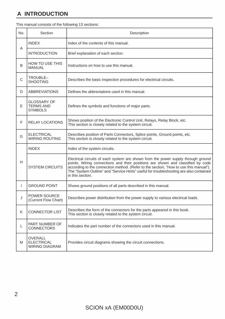
This manual consists of the following 13 sections:
No. Section Description
AINDEX Index of the contents of this manual.
AINTRODUCTION Brief explanation of each section.
B HOW TO USE THISMANUAL Instructions on how to use this manual.
C TROUBLE–SHOOTING Describes the basic inspection procedures for electrical circuits.
D ABBREVIATIONS Defines the abbreviations used in this manual.
EGLOSSARY OFTERMS ANDSYMBOLS
Defines the symbols and functions of major parts.
F RELAY LOCATIONS Shows position of the Electronic Control Unit, Relays, Relay Block, etc.This section is closely related to the system circuit.
G ELECTRICALWIRING ROUTING
Describes position of Parts Connectors, Splice points, Ground points, etc.This section is closely related to the system circuit.
H
INDEX Index of the system circuits.
HSYSTEM CIRCUITS
Electrical circuits of each system are shown from the power supply through groundpoints. Wiring connections and their positions are shown and classified by codeaccording to the connection method. (Refer to the section, ”How to use this manual”).The ”System Outline” and ”Service Hints” useful for troubleshooting are also containedin this section.
I GROUND POINT Shows ground positions of all parts described in this manual.
J POWER SOURCE(Current Flow Chart) Describes power distribution from the power supply to various electrical loads.
K CONNECTOR LIST Describes the form of the connectors for the parts appeared in this book.This section is closely related to the system circuit.
L PART NUMBER OFCONNECTORS Indicates the part number of the connectors used in this manual.
MOVERALLELECTRICALWIRING DIAGRAM
Provides circuit diagrams showing the circuit connections.
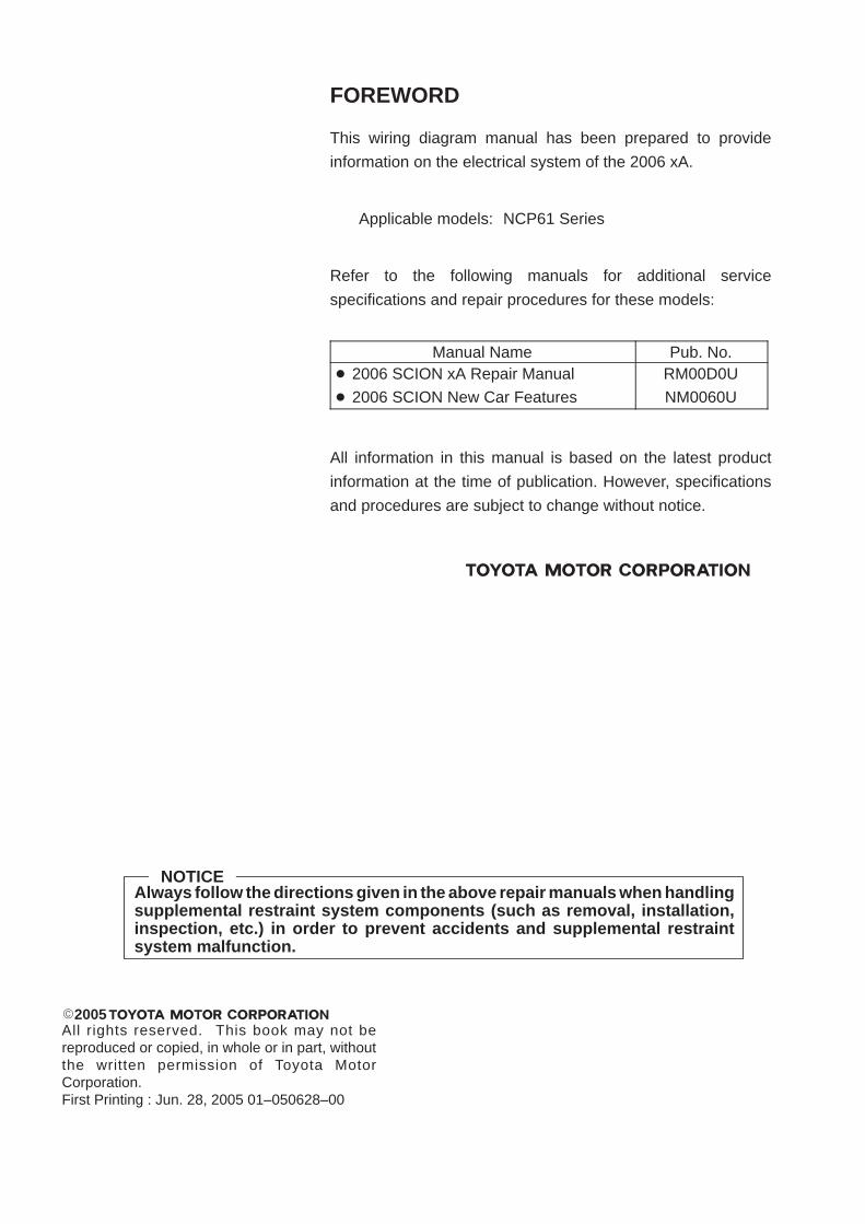
NOTICEAlways follow the directions given in the above repair manuals when handlingsupplemental restraint system components (such as removal, installation,inspection, etc.) in order to prevent accidents and supplemental restraintsystem malfunction.
2005All rights reserved. This book may not bereproduced or copied, in whole or in part, withoutthe written permission of Toyota MotorCorporation.First Printing : Jun. 28, 2005 01–050628–00
FOREWORD
This wiring diagram manual has been prepared to provide
information on the electrical system of the 2006 xA.
Applicable models: NCP61 Series
Refer to the following manuals for additional service
specifications and repair procedures for these models:
Manual Name Pub. No. 2006 SCION xA Repair Manual
2006 SCION New Car Features
RM00D0U
NM0060U
All information in this manual is based on the latest product
information at the time of publication. However, specifications
and procedures are subject to change without notice.

SCION xA (EM00D0U)
3
HOW TO USE THIS MANUAL B
This manual provides information on the electrical circuits installed on vehicles bydividing them into a circuit for each system.
The actual wiring of each system circuit is shown from the point where the powersource is received from the battery as far as each ground point. (All circuitdiagrams are shown with the switches in the OFF position.)
When troubleshooting any problem, first understand the operation of the circuitwhere the problem was detected (see System Circuit section), the power sourcesupplying power to that circuit (see Power Source section), and the ground points(see Ground Point section). See the System Outline to understand the circuitoperation.
When the circuit operation is understood, begin troubleshooting of the problemcircuit to isolate the cause. Use Relay Location and Electrical Wiring Routingsections to find each part, junction block and wiring harness connectors, wiringharness and wiring harness connectors and ground points of each system circuit.Internal wiring for each junction block is also provided for better understanding ofconnection within a junction block.Wiring related to each system is indicated in each system circuit by arrows(from__, to__). When overall connections are required, see the Overall ElectricalWiring Diagram at the end of this manual.
[B]W
– R
G –
W
Ski
d C
ontr
ol E
CU
with
Act
uato
r
G –
W
C7
Y –
G
Com
bina
tion
Met
er
R –
L
Rea
rLi
ghts
R –
L
(S/D
)(S
/D)
(S/D
)
(W/G
)
G –
B
W –
B
W –
B
Rea
r C
ombi
natio
nR
6
W –
BW
– B
Rea
r C
ombi
natio
nR
7
W –
BG
– R
Sto
p
Sto
p
G –
RG
– R
7
LL
R
L
Stop Light
2
(BAT)
15ASTOP
(IG)
IBIB
7.5AGAUGE
3 41
[A]
S6Stop Light SW
G – W
1
2
[D]
[C]
[E]
[F]
[G]
[N]
L4Light Failure Sensor
3C
3C
15 IE1
IE114
7
15
48
13
4
50
[K]
[H]
[I]
[L]
[M]
[J]
11
H17High MountedStop Light
(Shielded)
BO BL
BV1W – B
G – RBV1
1
2
6
3
3
4
1
1
12
Ligh
t RH
Ligh
t LH
4
SCION xA (EM00D0U)
B HOW TO USE THIS MANUAL
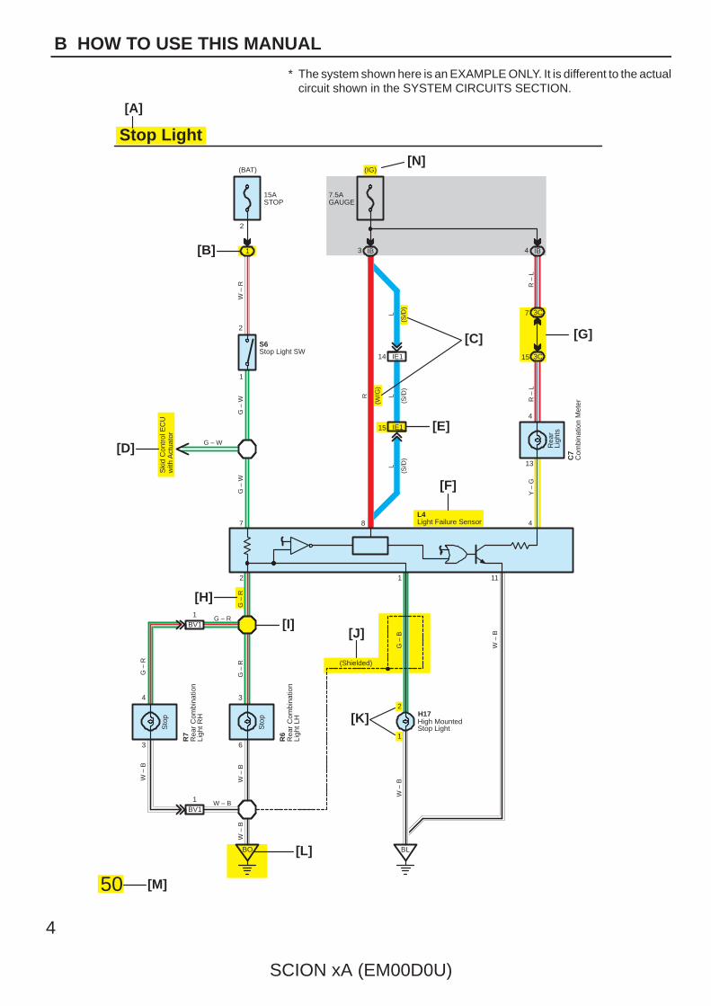
* The system shown here is an EXAMPLE ONLY. It is different to the actualcircuit shown in the SYSTEM CIRCUITS SECTION.

SCION xA (EM00D0U)
5
B
[A] : System Title
[B] : Indicates a Relay Block. No shading is used andonly the Relay Block No. is shown to distinguish itfrom the J/BExample: Indicates Relay Block No.1
[C] : ( ) is used to indicate different wiring andconnector, etc. when the vehicle model, enginetype, or specification is different.
[D] : Indicates related system.
[E] : Indicates the wiring harness and wiring harnessconnector. The wiring harness with male terminal isshown with arrows ( ).Outside numerals are pin numbers.
Female Male ( )
The first letter of the code for each wiring harnessand wiring harness connector(s) indicates thecomponent’s location, e.g, ”E” for the EngineCompartment, ”I” for the Instrument Panel andSurrounding area, and ”B” for the Body andSurrounding area.
When more than one code has the first and secondletters in common, followed by numbers (e.g, IH1,IH2), this indicates the same type of wiring harnessand wiring harness connector.
[F] : Represents a part (all parts are shown in sky blue).The code is the same as the code used in partsposition.
[G] : Junction Block (The number in the circle is the J/BNo. and the connector code is shown beside it).Junction Blocks are shaded to clearly separatethem from other parts.
3C indicates thatit is insideJunction BlockNo.3
Example:
[H] : Indicates the wiring color.
Wire colors are indicated by an alphabetical code.
B = Black W = White BR = Brown
L = Blue V = Violet SB = Sky Blue
R = Red G = Green LG = Light Green
P = Pink Y = Yellow GR = Gray
O = Orange
The first letter indicates the basic wire color and thesecond letter indicates the color of the stripe.
Example: L – Y
L(Blue)
Y(Yellow)
[I] : Indicates a wiring Splice Point
Example:
[J] : Indicates a shielded cable.
[K] : Indicates the pin number of the connector.The numbering system is different for female andmale connectors.
Example: Numbered in orderfrom upper left tolower right
Numbered in orderfrom upper right tolower left
Female Male
[L] : Indicates a ground point.
The first letter of the code for each ground point(s)indicates the component’s location, e.g, ”E” for theEngine Compartment, ”I” for the Instrument Paneland Surrounding area, and ”B” for the Body andSurrounding area.
[M] : Page No.
[N] : Indicates the ignition key position(s) when thepower is supplied to the fuse(s).
[O]
[P]
[Q]
[R]
[S]
[T]
6
SCION xA (EM00D0U)
B HOW TO USE THIS MANUAL
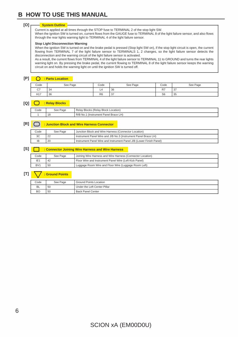
Current is applied at all times through the STOP fuse to TERMINAL 2 of the stop light SW.When the ignition SW is turned on, current flows from the GAUGE fuse to TERMINAL 8 of the light failure sensor, and also flowsthrough the rear lights warning light to TERMINAL 4 of the light failure sensor.
Stop Light Disconnection WarningWhen the ignition SW is turned on and the brake pedal is pressed (Stop light SW on), if the stop light circuit is open, the currentflowing from TERMINAL 7 of the light failure sensor to TERMINALS 1, 2 changes, so the light failure sensor detects thedisconnection and the warning circuit of the light failure sensor is activated.As a result, the current flows from TERMINAL 4 of the light failure sensor to TERMINAL 11 to GROUND and turns the rear lightswarning light on. By pressing the brake pedal, the current flowing to TERMINAL 8 of the light failure sensor keeps the warningcircuit on and holds the warning light on until the ignition SW is turned off.
: Parts Location
Code See Page Code See Page Code See Page
C7 34 L4 36 R7 37
H17 36 R6 37 S6 35
: Relay Blocks
Code See Page Relay Blocks (Relay Block Location)
1 18 R/B No.1 (Instrument Panel Brace LH)
: Junction Block and Wire Harness Connector
Code See Page Junction Block and Wire Harness (Connector Location)
3C 22 Instrument Panel Wire and J/B No.3 (Instrument Panel Brace LH)
IB 20 Instrument Panel Wire and Instrument Panel J/B (Lower Finish Panel)
: Connector Joining Wire Harness and Wire Harness
Code See Page Joining Wire Harness and Wire Harness (Connector Location)
IE1 42 Floor Wire and Instrument Panel Wire (Left Kick Panel)
BV1 50 Luggage Room Wire and Floor Wire (Luggage Room Left)
: Ground Points
Code See Page Ground Points Location
BL 50 Under the Left Center Pillar
BO 50 Back Panel Center
System Outline
SCION xA (EM00D0U)
7
B
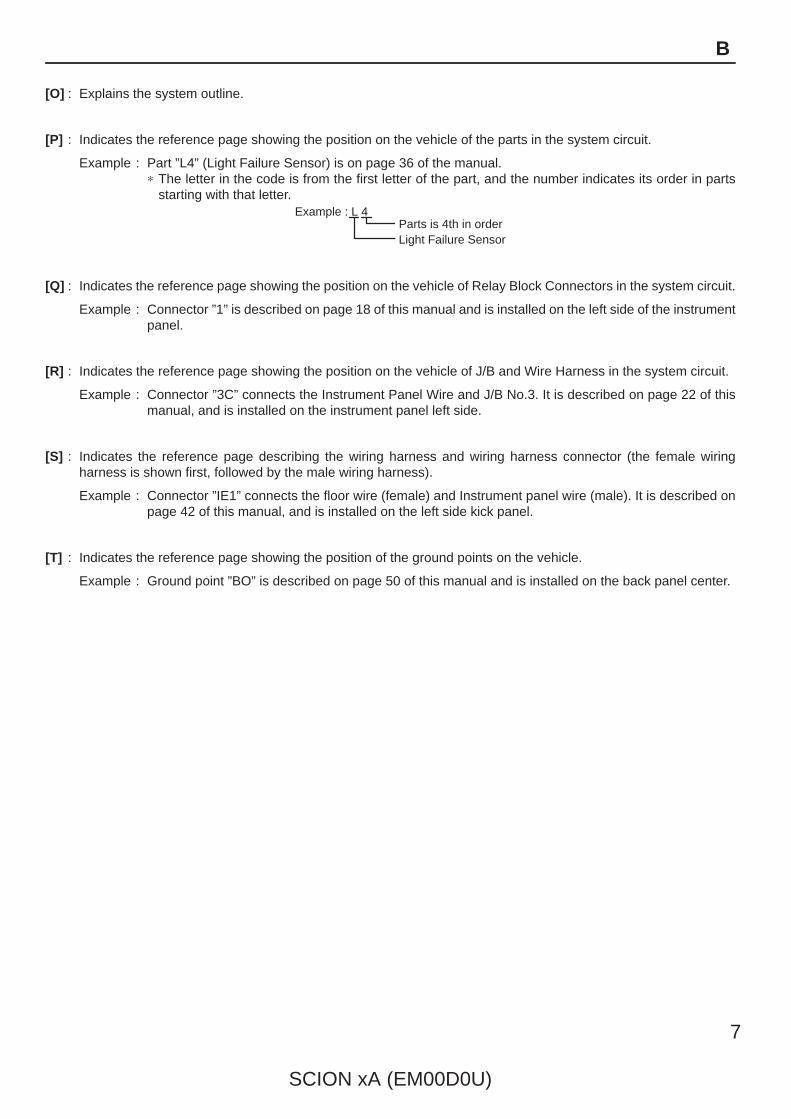
[O] : Explains the system outline.
[P] : Indicates the reference page showing the position on the vehicle of the parts in the system circuit.
Example : Part ”L4” (Light Failure Sensor) is on page 36 of the manual.∗ The letter in the code is from the first letter of the part, and the number indicates its order in parts
starting with that letter.Example : L 4 Á
ÁParts is 4th in orderLight Failure Sensor
[Q] : Indicates the reference page showing the position on the vehicle of Relay Block Connectors in the system circuit.
Example : Connector ”1” is described on page 18 of this manual and is installed on the left side of the instrumentpanel.
[R] : Indicates the reference page showing the position on the vehicle of J/B and Wire Harness in the system circuit.
Example : Connector ”3C” connects the Instrument Panel Wire and J/B No.3. It is described on page 22 of thismanual, and is installed on the instrument panel left side.
[S] : Indicates the reference page describing the wiring harness and wiring harness connector (the female wiringharness is shown first, followed by the male wiring harness).
Example : Connector ”IE1” connects the floor wire (female) and Instrument panel wire (male). It is described onpage 42 of this manual, and is installed on the left side kick panel.
[T] : Indicates the reference page showing the position of the ground points on the vehicle.
Example : Ground point ”BO” is described on page 50 of this manual and is installed on the back panel center.
8
SCION xA (EM00D0U)
B HOW TO USE THIS MANUAL
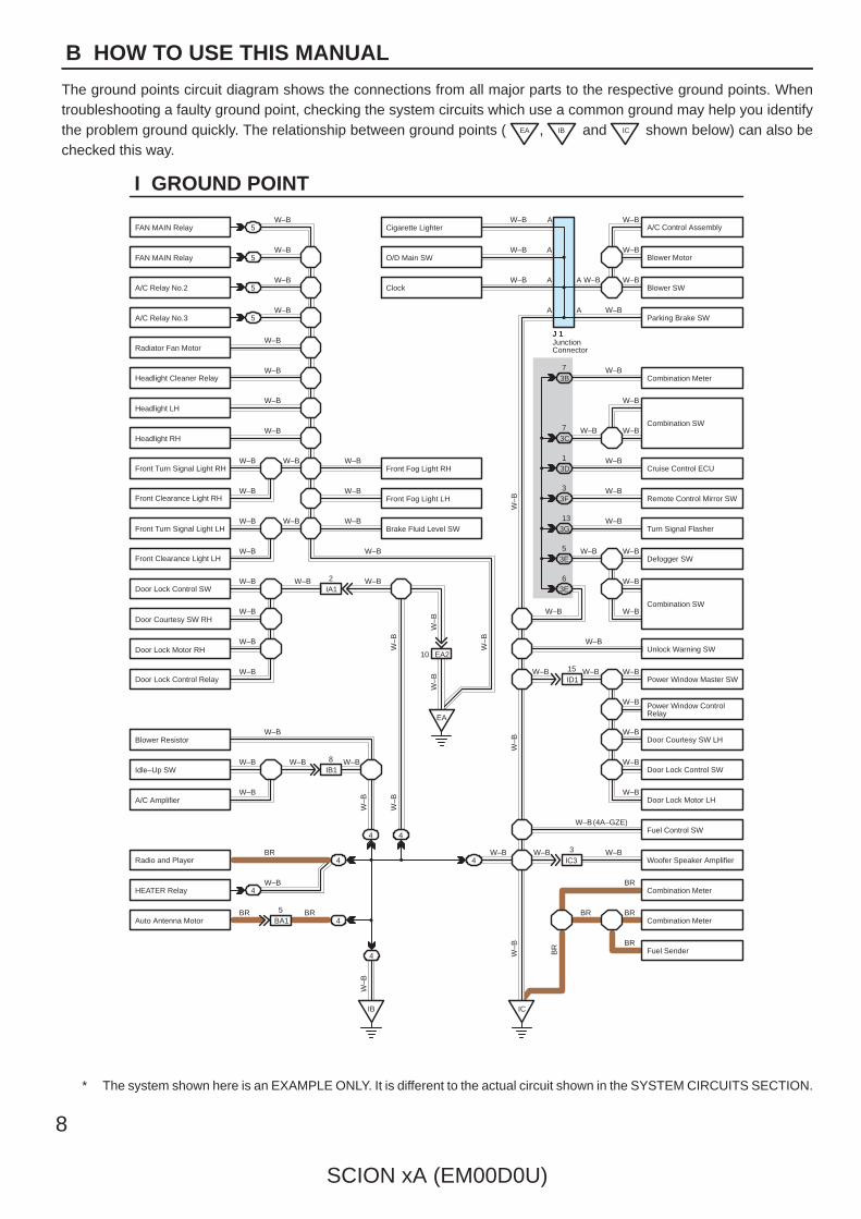
The ground points circuit diagram shows the connections from all major parts to the respective ground points. Whentroubleshooting a faulty ground point, checking the system circuits which use a common ground may help you identifythe problem ground quickly. The relationship between ground points ( EA , IB and IC shown below) can also bechecked this way.
5
5
5
5
4
4
4
4
4BA15
IB18
EA2
ID115
IC33
IA12
W–B
W–B
W–B
W–B
W–B
W–B
W–B
W–B
W–B W–B
W–B
W–B W–B
W–B
W–B W–B W–B
W–B
W–B
W–B
W–B
W–B
W–B
W–B
W–B W–B W–B
W–B
BR
W–B
BR BR
W–B
W–BW–B
W–B
W–B
W–B
W–BW–B W–B
W–B
W–B
W–B
W–B
W–B
BR
W–B
BRBR
BR
W–B(4A–GZE)
W–BW–B
EA
IB IC
4
4
3E5
3E6
3G13
3F3
3D1
3B7
W–B
W–B
W–BW–B
W–B
W–B
W–B
W–B
W–B
W–B
W–B
W–B
W–B
W–B
W–B3C7
10
A
A
A
A
A
A
JunctionConnector
J 1
W–B
W–B
W–B
W–B
BR
W–B
W–B
W–B
W–B
W–B
W–B
I GROUND POINT
FAN MAIN Relay
FAN MAIN Relay
A/C Relay No.2
A/C Relay No.3
Radiator Fan Motor
Headlight Cleaner Relay
Headlight LH
Headlight RH
Front Fog Light LH
Brake Fluid Level SW
Front Fog Light RHFront Turn Signal Light RH
Front Clearance Light RH
Front Turn Signal Light LH
Front Clearance Light LH
Door Lock Control SW
Door Courtesy SW RH
Door Lock Motor RH
Door Lock Control Relay
Blower Resistor
Idle–Up SW
A/C Amplifier
Radio and Player
HEATER Relay
Auto Antenna Motor
A/C Control Assembly
Blower Motor
Blower SW
Parking Brake SW
Combination Meter
Combination SW
Cruise Control ECU
Remote Control Mirror SW
Turn Signal Flasher
Defogger SW
Unlock Warning SW
Power Window Master SW
Power Window ControlRelay
Door Courtesy SW LH
Door Lock Control SW
Door Lock Motor LH
Fuel Control SW
Woofer Speaker Amplifier
Combination Meter
Combination Meter
Fuel Sender
Cigarette Lighter
O/D Main SW
Clock
Combination SW
* The system shown here is an EXAMPLE ONLY. It is different to the actual circuit shown in the SYSTEM CIRCUITS SECTION.
SCION xA (EM00D0U)
9
B
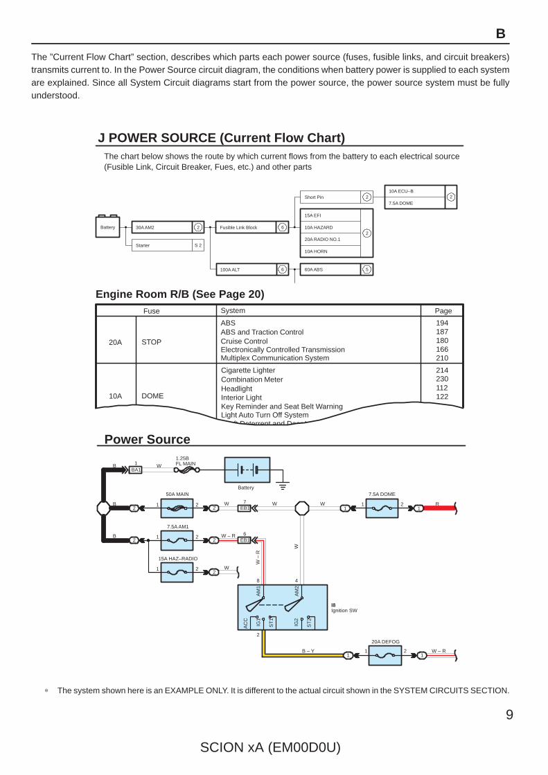
The ”Current Flow Chart” section, describes which parts each power source (fuses, fusible links, and circuit breakers)transmits current to. In the Power Source circuit diagram, the conditions when battery power is supplied to each systemare explained. Since all System Circuit diagrams start from the power source, the power source system must be fullyunderstood.
AM
2
AM
1
IG2
AC
C
IG1
ST
1
ST
2
W –
R
W
J POWER SOURCE (Current Flow Chart)The chart below shows the route by which current flows from the battery to each electrical source(Fusible Link, Circuit Breaker, Fues, etc.) and other parts
30A AM2
Starter
Battery Fusible Link Block
100A ALT
2 6
6
Short Pin10A ECU–B
7.5A DOME2
15A EFI
10A HAZARD
20A RADIO NO.1
10A HORN
60A ABS
2
2
S 2
5
Engine Room R/B (See Page 20)
194187180166210
214230112122
Page
ABSABS and Traction ControlCruise ControlElectronically Controlled TransmissionMultiplex Communication System
Fuse
STOP20A
10A DOME
Cigarette LighterCombination MeterHeadlightInterior LightKey Reminder and Seat Belt WarningLight Auto Turn Off System
System
Theft Deterrent and Door Lock Control
1.25BFL MAIN
Power Source
50A MAIN
4
11 2
1W – R
20A DEFOG
B – Y
8
2
I8
W – R
Ignition SW
11
7.5A DOME
21
RWEB1
7
EB1
BA11
6
W
WW
Battery
B
B
B2
21
22
2
2
7.5A AM1
15A HAZ–RADIO
1
212
W
∗ The system shown here is an EXAMPLE ONLY. It is different to the actual circuit shown in the SYSTEM CIRCUITS SECTION.
K CONNECTOR LIST
1 2 3 4
Dark GrayI14
1 2 3 4
5 6 7 8
I15
1 2 3 4 5 76
GrayI16[A] [C]
K CONNECTOR LIST
1 2 3 4 56 7 8 9 10 11 12 13
1234513 6789101112
BA1 Black BD2 Gray [F][E]
1 2 3 45 6 7 8 9 10 11 11
4 3 2 1
5678910
A BA A B C C C
D DD D
BAA
AA
AAA A 1
1 2 1 2
[B] Black
J1 J4 K1 K2 L1Dark Gray
[D]
10
SCION xA (EM00D0U)
B HOW TO USE THIS MANUAL
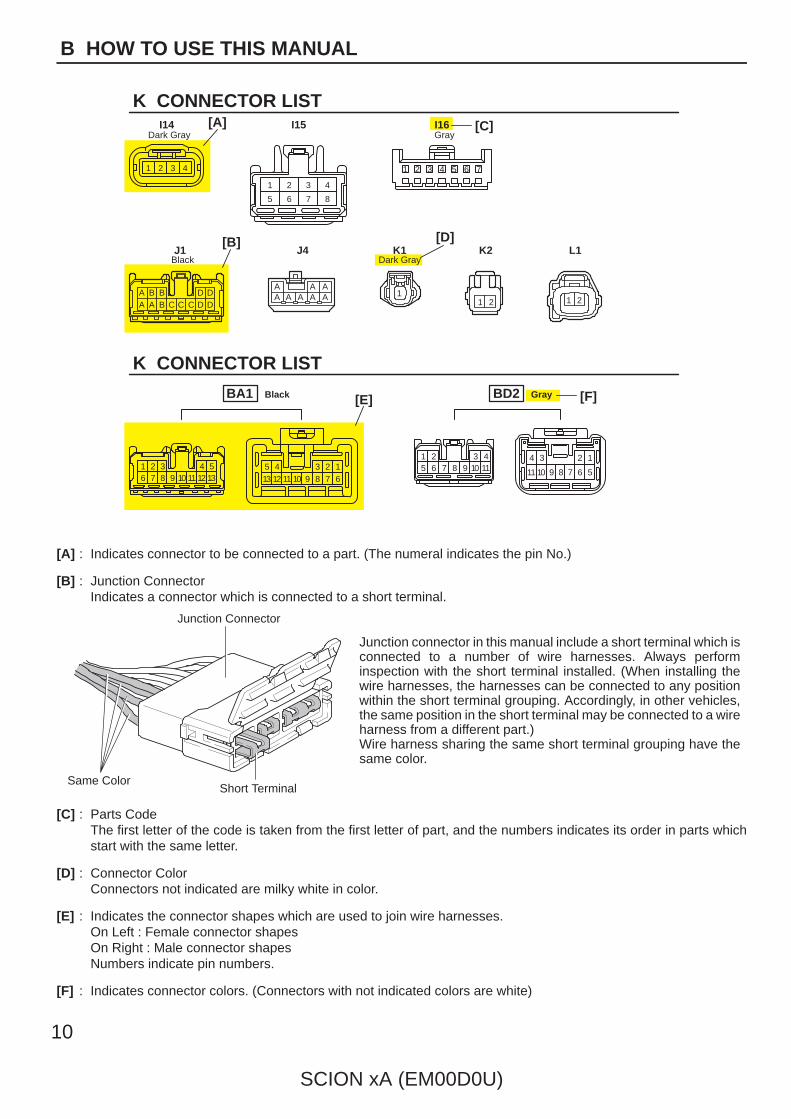
[A] : Indicates connector to be connected to a part. (The numeral indicates the pin No.)
[B] : Junction ConnectorIndicates a connector which is connected to a short terminal.
Junction Connector
Short TerminalSame Color
Junction connector in this manual include a short terminal which isconnected to a number of wire harnesses. Always performinspection with the short terminal installed. (When installing thewire harnesses, the harnesses can be connected to any positionwithin the short terminal grouping. Accordingly, in other vehicles,the same position in the short terminal may be connected to a wireharness from a different part.)Wire harness sharing the same short terminal grouping have thesame color.
[C] : Parts CodeThe first letter of the code is taken from the first letter of part, and the numbers indicates its order in parts whichstart with the same letter.
[D] : Connector ColorConnectors not indicated are milky white in color.
[E] : Indicates the connector shapes which are used to join wire harnesses.On Left : Female connector shapesOn Right : Male connector shapesNumbers indicate pin numbers.
[F] : Indicates connector colors. (Connectors with not indicated colors are white)
A 1
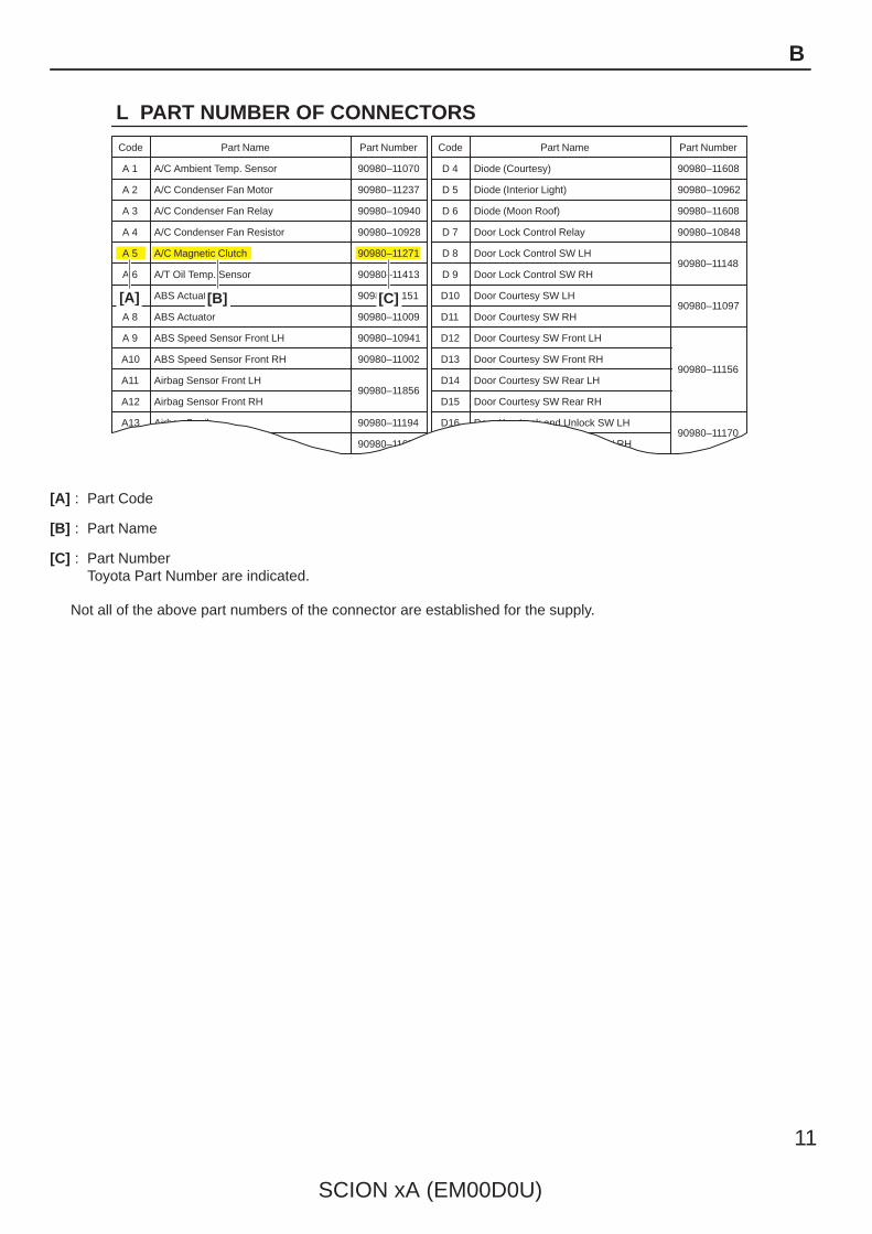
L PART NUMBER OF CONNECTORS
A/C Ambient Temp. Sensor
Code
90980–11070
Part Number
D 4 Diode (Courtesy)
Code
90980–11608
A 2 A/C Condenser Fan Motor 90980–11237 D 5 Diode (Interior Light) 90980–10962
A 3 A/C Condenser Fan Relay 90980–10940 D 6 Diode (Moon Roof) 90980–11608
A 4 A/C Condenser Fan Resistor 90980–10928
90980–11271
D 7 Door Lock Control Relay 90980–10848
A 5 A/C Magnetic Clutch
90980–11413
D 8 Door Lock Control SW LH90980–11148
A 6 A/T Oil Temp. Sensor
90980–11151
D 9 Door Lock Control SW RH
A 7 ABS Actuator
90980–11009
Door Courtesy SW LH90980–11097
A 8 ABS Actuator
90980–10941
Door Courtesy SW RH
A 9 ABS Speed Sensor Front LH
90980–11002
Door Courtesy SW Front LH
ABS Speed Sensor Front RH
90980–11856
Door Courtesy SW Front RH90980–11156
Airbag Sensor Front LH Door Courtesy SW Rear LH
Airbag Sensor Front RH Door Courtesy SW Rear RH
A10
A11
A12
A13 Airbag Squib 90980–11194 Door Key Lock and Unlock SW LH90980–11170
90980–11070
D10
D11
D12
D13
D14
D15
D16
D17 Door Key Lock and Unlock SW RH
Part NumberPart NamePart Name
[A] [B] [C]
SCION xA (EM00D0U)
11
B
[A] : Part Code
[B] : Part Name
[C] : Part NumberToyota Part Number are indicated.
Not all of the above part numbers of the connector are established for the supply.
To Ignition SWIG Terminal
Fuse
VoltmeterSW 1
Relay
SW 2 Solenoid
[A]
[B]
[C]
Ohmmeter
SW
Ohmmeter
Diode
Digital Type Analog Type
12
SCION xA (EM00D0U)
C TROUBLESHOOTING
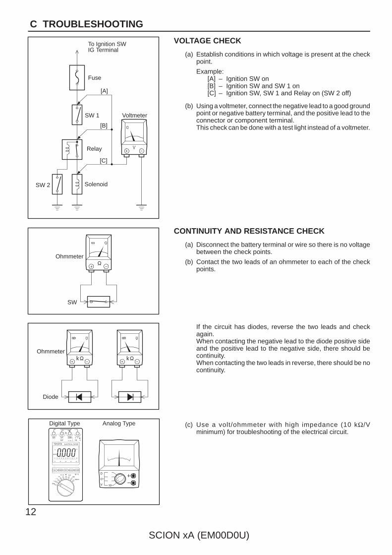
VOLTAGE CHECK
(a) Establish conditions in which voltage is present at the checkpoint.
Example:[A] – Ignition SW on[B] – Ignition SW and SW 1 on[C] – Ignition SW, SW 1 and Relay on (SW 2 off)
(b) Using a voltmeter, connect the negative lead to a good groundpoint or negative battery terminal, and the positive lead to theconnector or component terminal.This check can be done with a test light instead of a voltmeter.
CONTINUITY AND RESISTANCE CHECK
(a) Disconnect the battery terminal or wire so there is no voltagebetween the check points.
(b) Contact the two leads of an ohmmeter to each of the checkpoints.
If the circuit has diodes, reverse the two leads and checkagain.When contacting the negative lead to the diode positive sideand the positive lead to the negative side, there should becontinuity.When contacting the two leads in reverse, there should be nocontinuity.
(c) Use a volt/ohmmeter with high impedance (10 kΩ/Vminimum) for troubleshooting of the electrical circuit.
To Ignition SWIG Terminal
Test Light
RelayLight
SW 2 Solenoid
Disconnect
Short [A]
DisconnectDisconnect
SW 1
Fuse Case
Short [B]
Short [C]
Pull Up
Press Down Press Down
Pull Up
SCION xA (EM00D0U)
13
C
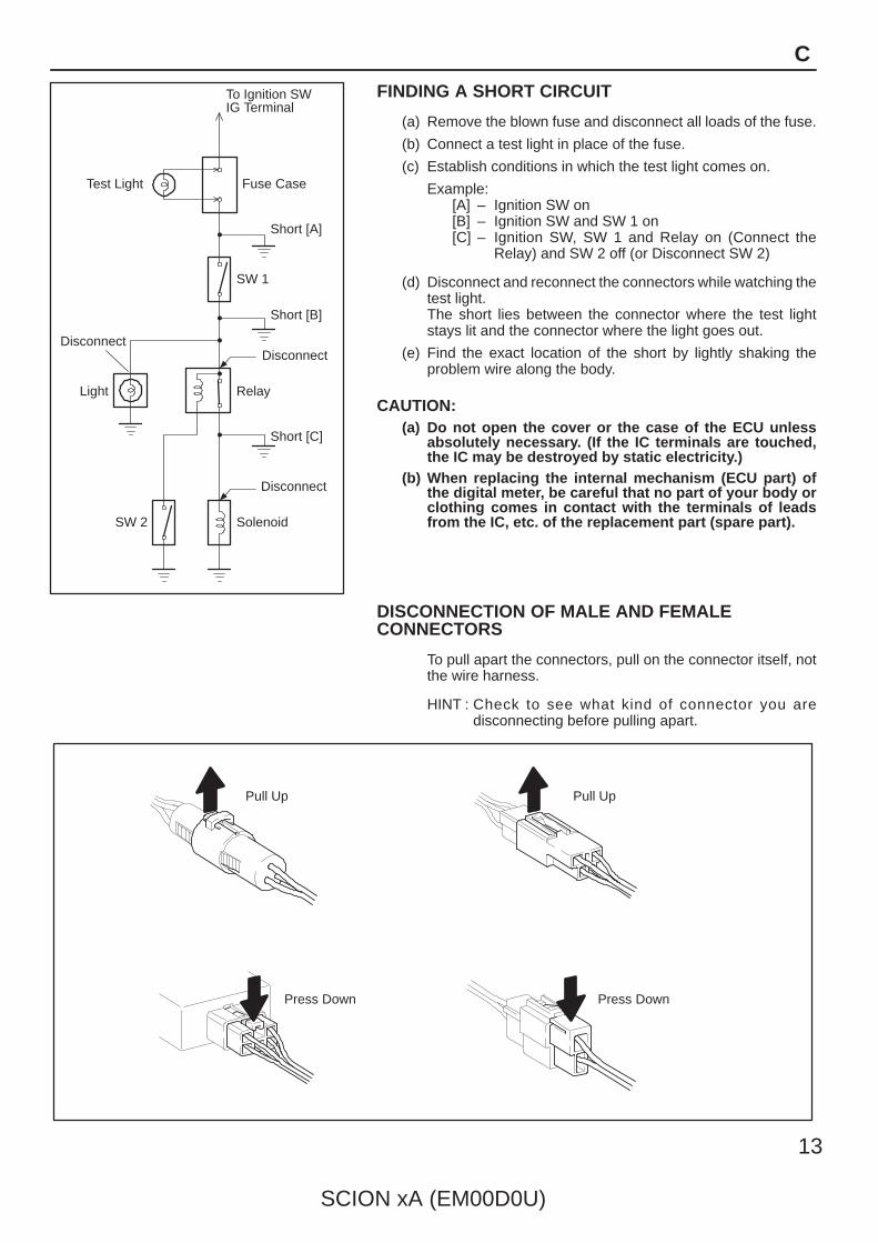
FINDING A SHORT CIRCUIT
(a) Remove the blown fuse and disconnect all loads of the fuse.
(b) Connect a test light in place of the fuse.
(c) Establish conditions in which the test light comes on.
Example:[A] – Ignition SW on[B] – Ignition SW and SW 1 on[C] – Ignition SW, SW 1 and Relay on (Connect the
Relay) and SW 2 off (or Disconnect SW 2)
(d) Disconnect and reconnect the connectors while watching thetest light.The short lies between the connector where the test lightstays lit and the connector where the light goes out.
(e) Find the exact location of the short by lightly shaking theproblem wire along the body.
CAUTION:(a) Do not open the cover or the case of the ECU unless
absolutely necessary. (If the IC terminals are touched,the IC may be destroyed by static electricity.)
(b) When replacing the internal mechanism (ECU part) ofthe digital meter, be careful that no part of your body orclothing comes in contact with the terminals of leadsfrom the IC, etc. of the replacement part (spare part).
DISCONNECTION OF MALE AND FEMALECONNECTORS
To pull apart the connectors, pull on the connector itself, notthe wire harness.
HINT : Check to see what kind of connector you aredisconnecting before pulling apart.
(mm)
Reference:
ToolUpExample:(Case 1)
Terminal Retainer
Terminal Retainer
[Retainer at Full Lock Position]
[Retainer at Temporary Lock Position]
StopperTerminalRetainer
SecondaryLocking Device
Example:(Case 2)
14
SCION xA (EM00D0U)
C TROUBLESHOOTING
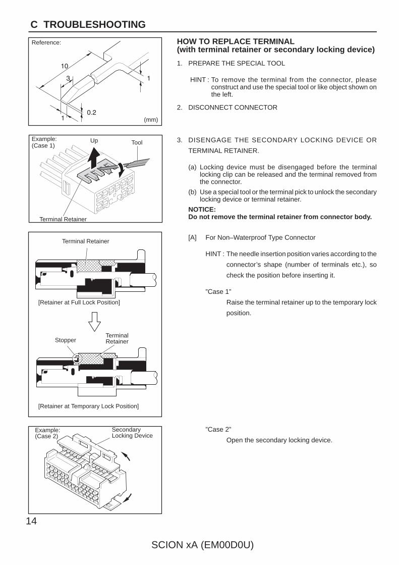
HOW TO REPLACE TERMINAL(with terminal retainer or secondary locking device)
1. PREPARE THE SPECIAL TOOL
HINT : To remove the terminal from the connector, pleaseconstruct and use the special tool or like object shown onthe left.
2. DISCONNECT CONNECTOR
3. DISENGAGE THE SECONDARY LOCKING DEVICE OR
TERMINAL RETAINER.
(a) Locking device must be disengaged before the terminallocking clip can be released and the terminal removed fromthe connector.
(b) Use a special tool or the terminal pick to unlock the secondarylocking device or terminal retainer.
NOTICE:Do not remove the terminal retainer from connector body.
[A] For Non–Waterproof Type Connector
HINT : The needle insertion position varies according to the
connector’s shape (number of terminals etc.), so
check the position before inserting it.
”Case 1”
Raise the terminal retainer up to the temporary lock
position.
”Case 2”
Open the secondary locking device.

ToolTab
Tab
TerminalRetainer
Access Hole( Mark)
Tool
Tool
[Female]
Example:
[Male]
(Case 1)
[Male] [Female]
Retainerat Full Lock Position
Retainerat Temporary Lock Position
Terminal Retainer
[Male] Press Down [Female]Press Down
ToolTool
Example:(Case 2)
SCION xA (EM00D0U)
15
C
[B] For Waterproof Type Connector
HINT : Terminal retainer color is differentaccording to connector body.
Example:Terminal Retainer : Connector BodyBlack or White : GrayBlack or White : Dark GrayGray or White : Black
”Case 1”Type where terminal retainer is pulledup to the temporary lock position (PullType).
Insert the special tool into the terminalretainer access hole (Mark) and pullthe terminal retainer up to thetemporary lock position.
HINT : The needle insertion position variesaccording to the connector’s shape(Number of terminals etc.), so checkthe position before inserting it.
”Case 2”Type which cannot be pulled as far asPower Lock insert the tool straight intothe access hole of terminal retainer asshown.
Retainer atFull Lock Position
[Male] [Female]
Retainer atTemporary Lock Position
Locking Lug
Tool
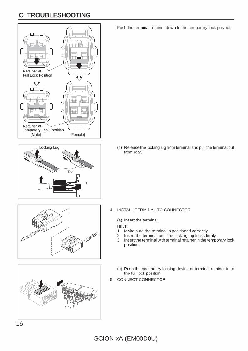
16
SCION xA (EM00D0U)
C TROUBLESHOOTING
Push the terminal retainer down to the temporary lock position.
(c) Release the locking lug from terminal and pull the terminal outfrom rear.
4. INSTALL TERMINAL TO CONNECTOR
(a) Insert the terminal.
HINT:1. Make sure the terminal is positioned correctly.2. Insert the terminal until the locking lug locks firmly.3. Insert the terminal with terminal retainer in the temporary lock
position.
(b) Push the secondary locking device or terminal retainer in tothe full lock position.
5. CONNECT CONNECTOR
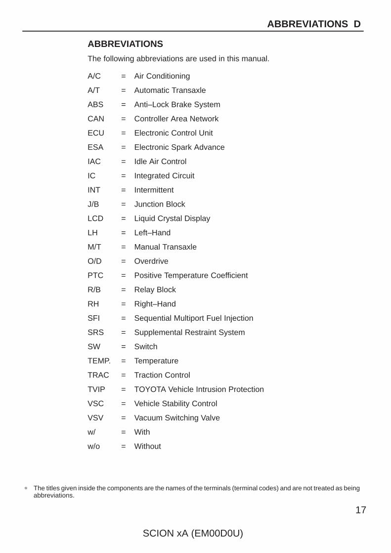
∗ The titles given inside the components are the names of the terminals (terminal codes) and are not treated as beingabbreviations.
SCION xA (EM00D0U)
17
ABBREVIATIONS D
ABBREVIATIONS
The following abbreviations are used in this manual.
A/C = Air Conditioning
A/T = Automatic Transaxle
ABS = Anti–Lock Brake System
CAN = Controller Area Network
ECU = Electronic Control Unit
ESA = Electronic Spark Advance
IAC = Idle Air Control
IC = Integrated Circuit
INT = Intermittent
J/B = Junction Block
LCD = Liquid Crystal Display
LH = Left–Hand
M/T = Manual Transaxle
O/D = Overdrive
PTC = Positive Temperature Coefficient
R/B = Relay Block
RH = Right–Hand
SFI = Sequential Multiport Fuel Injection
SRS = Supplemental Restraint System
SW = Switch
TEMP. = Temperature
TRAC = Traction Control
TVIP = TOYOTA Vehicle Intrusion Protection
VSC = Vehicle Stability Control
VSV = Vacuum Switching Valve
w/ = With
w/o = Without
18
SCION xA (EM00D0U)
E GLOSSARY OF TERMS AND SYMBOLS
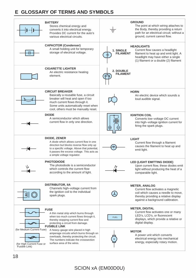
BATTERYStores chemical energy andconverts it into electrical energy.Provides DC current for the auto’svarious electrical circuits.
GROUNDThe point at which wiring attaches tothe Body, thereby providing a returnpath for an electrical circuit; without aground, current cannot flow.
CAPACITOR (Condenser)A small holding unit for temporarystorage of electrical voltage.
HEADLIGHTSCurrent flow causes a headlightfilament to heat up and emit light. Aheadlight may have either a single(1) filament or a double (2) filament
1. SINGLE FILAMENT
CIGARETTE LIGHTERAn electric resistance heatingelement.
2. DOUBLE FILAMENT
CIRCUIT BREAKERBasically a reusable fuse, a circuitbreaker will heat and open if toomuch current flows through it.Some units automatically reset whencool, others must be manually reset.
HORNAn electric device which sounds aloud audible signal.
DIODEA semiconductor which allowscurrent flow in only one direction.
IGNITION COILConverts low–voltage DC currentinto high–voltage ignition current forfiring the spark plugs.
DIODE, ZENERA diode which allows current flow in onedirection but blocks reverse flow only upto a specific voltage. Above that potential,it passes the excess voltage. This acts asa simple voltage regulator.
LIGHTCurrent flow through a filamentcauses the filament to heat up andemit light.
PHOTODIODEThe photodiode is a semiconductorwhich controls the current flowaccording to the amount of light.
LED (LIGHT EMITTING DIODE)Upon current flow, these diodes emitlight without producing the heat of acomparable light.
DISTRIBUTOR, IIAChannels high–voltage current fromthe ignition coil to the individualspark plugs.
METER, ANALOGCurrent flow activates a magneticcoil which causes a needle to move,thereby providing a relative displayagainst a background calibration.
FUSEA thin metal strip which burns throughwhen too much current flows through it,thereby stopping current flow andprotecting a circuit from damage.
FUSIBLE LINK
METER, DIGITALCurrent flow activates one or manyLED’s, LCD’s, or fluorescentdisplays, which provide a relative ordigital display.
FUEL
FUSIBLE LINKA heavy–gauge wire placed in highamperage circuits which burns through onoverloads, thereby protecting the circuit.The numbers indicate the crosssectionsurface area of the wires.
(for Medium Current Fuse)
(for High Current Fuse or Fusible Link)
MOTORA power unit which convertselectrical energy into mechanicalenergy, especially rotary motion.
M
SCION xA (EM00D0U)
19
E
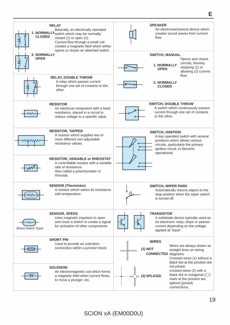
RELAYBasically, an electrically operatedswitch which may be normallyclosed (1) or open (2).Current flow through a small coilcreates a magnetic field which eitheropens or closes an attached switch.
1. NORMALLY CLOSED
2. NORMALLY OPEN
SWITCH, MANUALOpens and closescircuits, thereby
SPEAKERAn electromechanical device whichcreates sound waves from currentflow.
RELAY, DOUBLE THROWA relay which passes currentthrough one set of contacts or theother.
Opens and closescircuits, therebystopping (1) orallowing (2) currentflow.
1. NORMALLY OPEN
2. NORMALLY CLOSED
RESISTORAn electrical component with a fixedresistance, placed in a circuit toreduce voltage to a specific value.
SWITCH, DOUBLE THROWA switch which continuously passescurrent through one set of contactsor the other.
RESISTOR, TAPPEDA resistor which supplies two ormore different non adjustableresistance values.
SWITCH, IGNITIONA key operated switch with severalpositions which allows variouscircuits, particularly the primaryignition circuit, to becomeoperational.
RESISTOR, VARIABLE or RHEOSTATA controllable resistor with a variablerate of resistance.Also called a potentiometer orrheostat.
operational.
SENSOR (Thermistor)A resistor which varies its resistancewith temperature.
SWITCH, WIPER PARKAutomatically returns wipers to thestop position when the wiper switchis turned off.
(Reed Switch Type)
SENSOR, SPEEDUses magnetic impulses to openand close a switch to create a signalfor activation of other components.
TRANSISTORA solidstate device typically used asan electronic relay; stops or passescurrent depending on the voltageapplied at ”base”.
SHORT PINUsed to provide an unbrokenconnection within a junction block.
WIRESWires are always drawn asstraight lines on wiringdiagrams.Crossed wires (1) without ablack dot at the junction are
(1) NOT CONNECTED
SOLENOIDAn electromagnetic coil which formsa magnetic field when current flows,to move a plunger, etc.
black dot at the junction arenot joined;crossed wires (2) with ablack dot or octagonal ( )mark at the junction arespliced (joined)connections.
(2) SPLICED
20
SCION xA (EM00D0U)
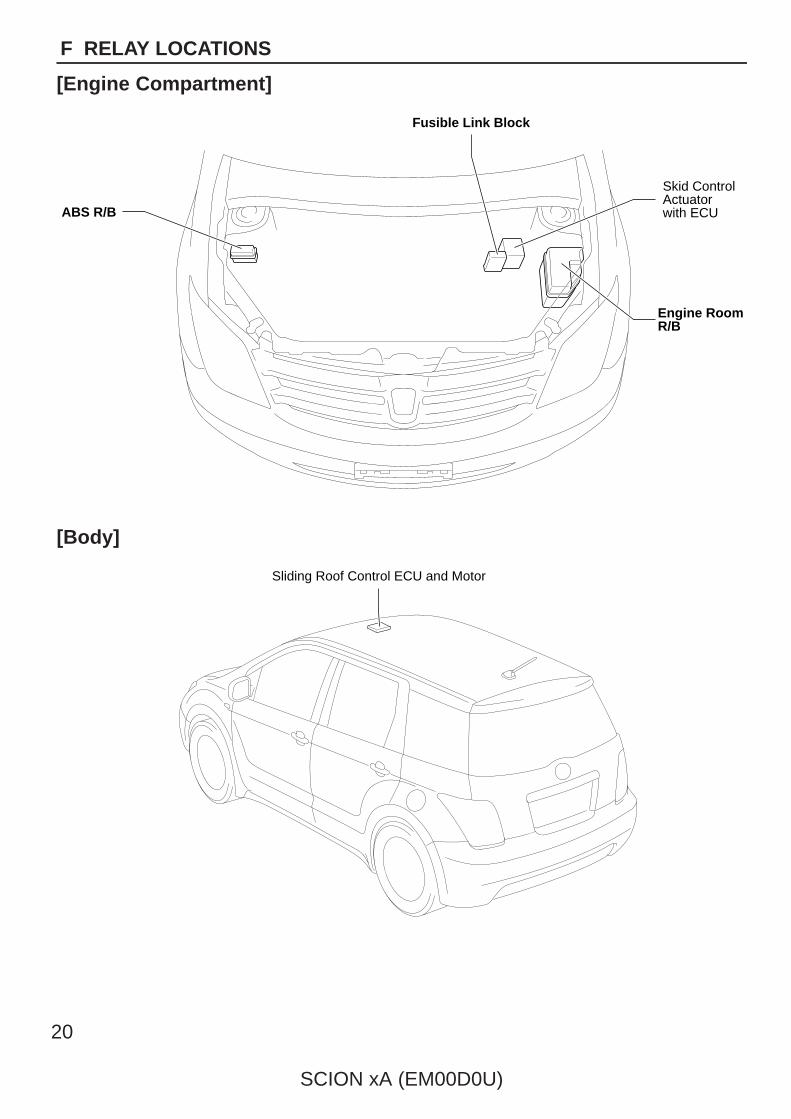
F RELAY LOCATIONS
[Engine Compartment]
Engine RoomR/B
Skid ControlActuatorwith ECUABS R/B
Fusible Link Block
[Body]
Sliding Roof Control ECU and Motor

Airbag Sensor Assembly
Engine Control Module
Instrument Panel J/B
Rear WindowDefogger Relay
Front Fog Light Relay
Illumination Relay
A/C AmplifierDoor Lock Control Relay
SCION xA (EM00D0U)
21
F
[Instrument Panel]
3 51
2
3 51
2
5
2
1
3
1
2
3 5
3 51
23 5
1
24
1
2
1
2
1
2
DO
ME
15A
15A
EFI
HO
RN
15A
15A
AM
2
ST
30A
*1 10A
*2
A/C
210
A10
A
7.5A
ST Relay
FAN NO.2 Relay FAN NO.1 Relay
EFI Relay
HORN Relay
50A HTR SUB1(for High Current)
HTR SUB1 Relay30A RDI(for High Current)
1 1
2 2
122
112
12
12
12
40A ABS NO.1
* 1:H-LP LH / H-LP LO LH* 2:H-LP RH / H-LP LO RH
22
SCION xA (EM00D0U)
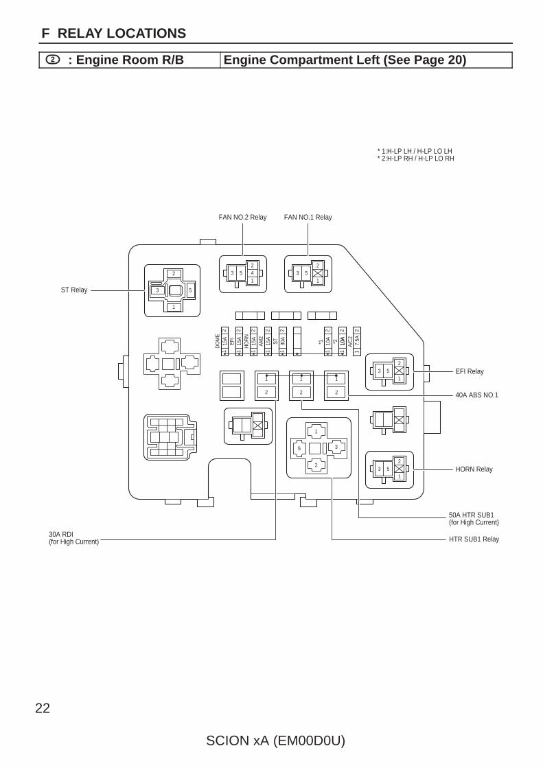
F RELAY LOCATIONS
2 : Engine Room R/B Engine Compartment Left (See Page 20)
SCION xA (EM00D0U)
23
F
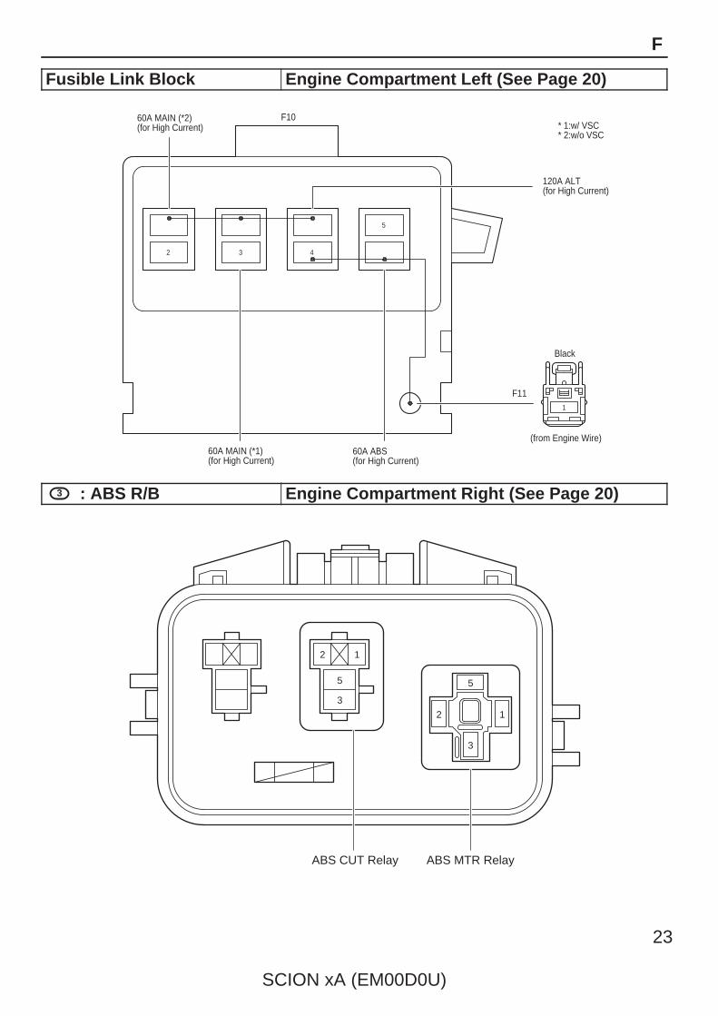
Fusible Link Block Engine Compartment Left (See Page 20)
60A MAIN (*2)(for High Current)
120A ALT(for High Current)
2 3 4
5
60A ABS(for High Current)
1
60A MAIN (*1)(for High Current)
* 1:w/ VSCF10
F11
Black
(from Engine Wire)
* 2:w/o VSC
3 : ABS R/B Engine Compartment Right (See Page 20)
12
3
5
3
ABS CUT Relay ABS MTR Relay
5
12
1
2
3456
3
21 4
56789
123
45 13
6789101112 114
3
21 5
678910
1
5
2
1
3
35
1 2
35
1 2
1
2
3456
12
3
456789
123
45
678910111213
12
34
567891011
1
HEATER Relay
POWER Relay
FLSH Relay
C/OPN Relay
1
2
1
2
1
2
GAUGE
10A
ACC
15A
7.5A
A. C
7.5A
ECU-IG
WIPER
25A
DEF
25A
7.5A
7.5A
OBD
ECU-B
25A
D/L
10A
10A
HAZ
STOP
10A
TAIL
15A
FOG
30A POWER(for High Current)
50A AM1(for High Current)
40A HTR(for High Current)
(from Floor Wire)
(from Floor Wire)
Gray
4(from Engine Room Main Wire)
(from Engine Room Main Wire)
(from Engine Room Main Wire)
1 2 3
4 5 6 7 8
Gray
1T
1C
1A
1B
1S
24
SCION xA (EM00D0U)
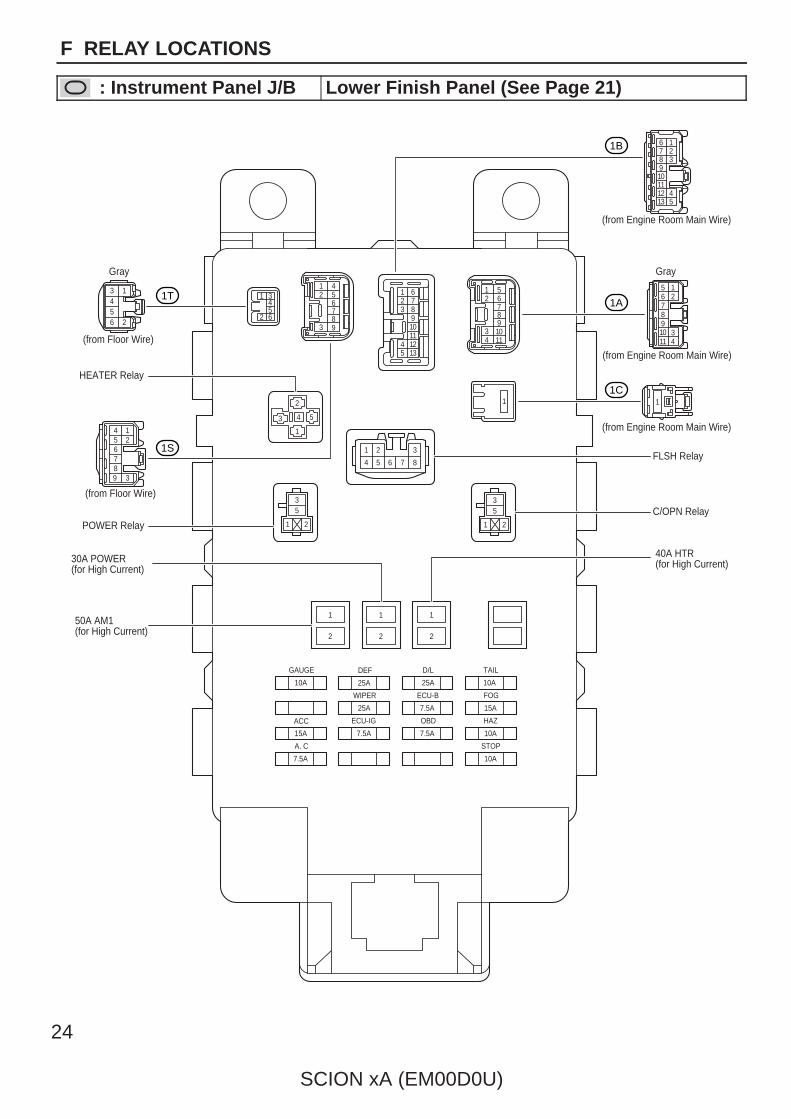
F RELAY LOCATIONS
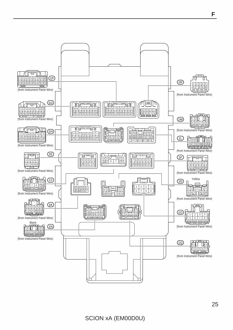
: Instrument Panel J/B Lower Finish Panel (See Page 21)
89
18 17
7
16
6
15
5
14
4
13
3
12
2
11
1
10
910
20 19
8
18
7
17
6
16
4
14
3
13
2
12
1
1115
55 4 3 2 110 9 8 7 6
3 2 1
45678912345
13 6789101112
5
10
4
9
3
8
2
7
1
6
4 3 2 1
10 9 8 7 6 57
14
6
13
5
12
4
11
3
10
2
9
1
8
123456789101112 1234
56789105678
1234
11
4 3 2 1
56789102
7 6 5 4 3
1
9
18
8
1716
76
1514
54
1312
32
11
1
10
3 4 5 6 7
13 14 15 16 17
2
12
1
11
8
18 19
9 10
201 2 3 4 56 7 8 9 10
987654
321
1 2 3 4 56 7 8 9 10 11 12 13
1 2 3 4 5 6 7 8 9
10 11 12 13 14 15 16 17 18
109876
54321
1 2 3 4 5 6
7 8 9 10 11 12
1 2 3 45 6 7 8 9 10 11
213 4 5 6 7
1 2 3 4
5 6 7 8
7
1413
65
1211
43
109
21
8
1 2 3 4
5 6 7 8 9 101 2 3 4
5 6 7 8 9 10
Black
(from Instrument Panel Wire)
(from Instrument Panel Wire)
(from Instrument Panel Wire)
(from Instrument Panel Wire)
(from Instrument Panel Wire)
(from Instrument Panel Wire)
(from Instrument Panel Wire)
(from Instrument Panel Wire)
(from Instrument Panel Wire)
(from Instrument Panel Wire)
(from Instrument Panel Wire)
(from Instrument Panel Wire)
(from Instrument Panel Wire)
(from Instrument Panel Wire)
Yellow
10111213141517 16
123456789
18
1P
1G
1H
1E
1J
1K
1N
1O
1Q
1D
1F
1L
1M
1R
SCION xA (EM00D0U)
25
F
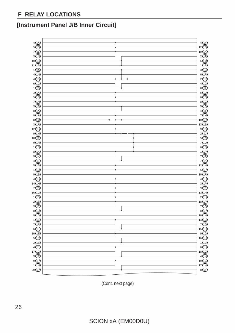
(Cont. next page)
1A4 1F4
1G12
1K10
1F2
1M5
1R1
1G3
1P6
1R2
1G4
1L8
1D5
1O6
1G8
1G5
1L4
1M7
1R10
1B13
1S9
1J2
1N5
1Q7
1Q6
1P1
1F7
1K7
1H12
1P5
1P10
1D4
1P3
1E9
1H13
1H2
1P18
1G7
1P8
1H10
1G14
1O7
1H15
1G9
1H16
1G1
1H6
1G18
1H4
1G10
1H17
1F8
1S5
1L7
1N3
1B10
1B11
1A1
1N4
1S4
1G6
1S1
1A3
1O5
1H7
1S3
1A8
1A9
1M8
1R3
1B12
1M9
1F10
1R9
1Q1
1K8
1K9
1T4
1B5
1D1
1B9
1B4
1H14
1S7
1G16
1B1
1B2
1T3
1D8
1D9
1E1
1P7
1E6
1E10
1R5
1E2
1E4
1G17
1E3
1P9
1H1
1P20
26
SCION xA (EM00D0U)
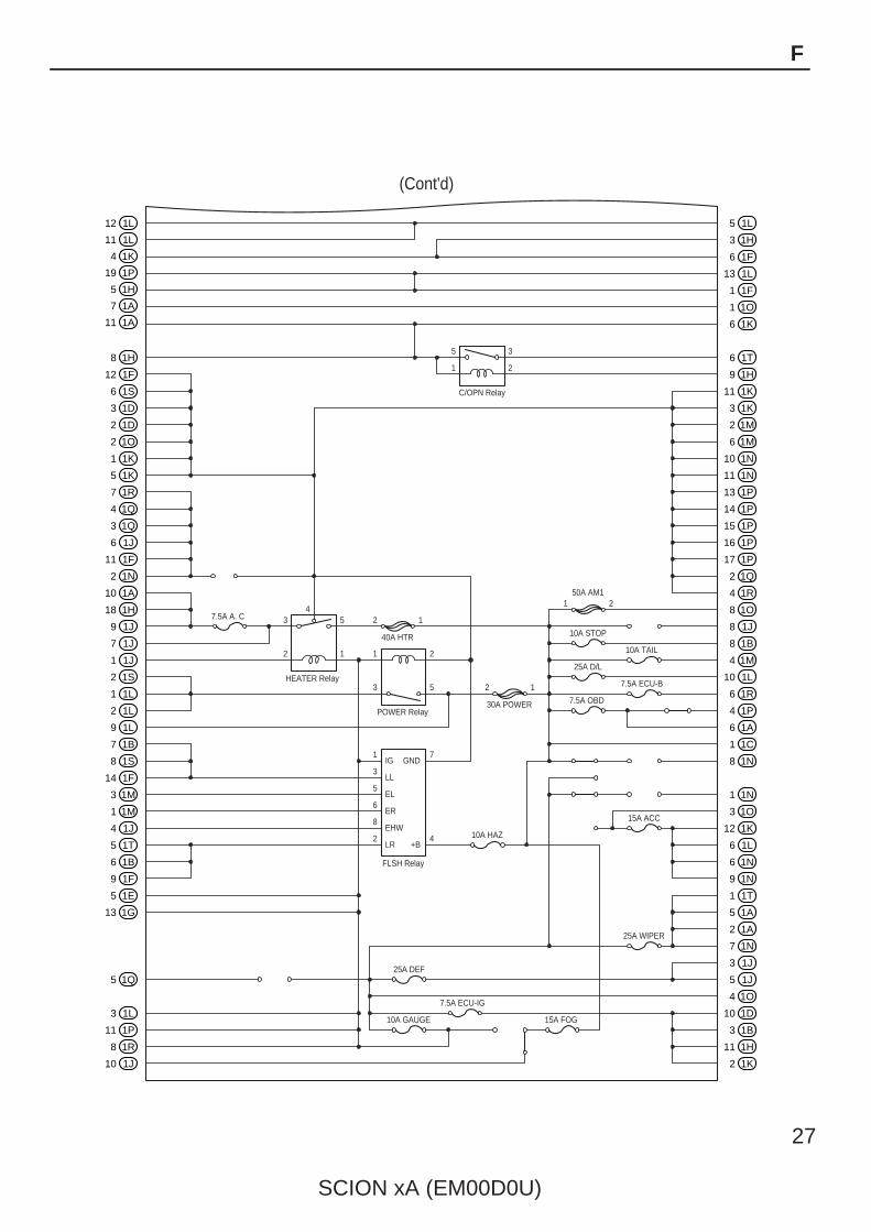
F RELAY LOCATIONS
[Instrument Panel J/B Inner Circuit]
5
1
3
2
C/OPN Relay
3
2
5
1
4
1
3
2
5HEATER Relay
POWER Relay
FLSH Relay
7
4
1
3
5
6
8
2
7.5A A. C 2 1
12
1 2
40A HTR
50A AM1
30A POWER
10A STOP
10A TAIL
25A D/L
7.5A ECU-B
7.5A OBD
10A HAZ
15A ACC
10A GAUGE
25A DEF
7.5A ECU-IG
15A FOG
25A WIPER
(Cont'd)
IG
LL
EL
ER
EHW
LR
GND
+B
1L12 1L5
1H3
1F6
1L13
1F1
1O1
1K6
1T6
1H9
1K11
1K3
1M2
1M6
1N10
1N11
1P13
1P14
1P15
1P16
1P17
1Q2
1R4
1O8
1J8
1B8
1M4
1L10
1R6
1P4
1A6
1C1
1N8
1N1
1O3
1K12
1L6
1N6
1N9
1T1
1A5
1A2
1N7
1J3
1J5
1O4
1D10
1B3
1H11
1K2
1L11
1K4
1P19
1H5
1A7
1A11
1H8
1F12
1S6
1D3
1D2
1O2
1K1
1K5
1R7
1Q4
1Q3
1J6
1F11
1N2
1A10
1H18
1J9
1J7
1J1
1S2
1L1
1L2
1L9
1B7
1S8
1F14
1M3
1M1
1J4
1T5
1B6
1F9
1E5
1G13
1Q5
1L3
1P11
1R8
1J10
SCION xA (EM00D0U)
27
F

28
SCION xA (EM00D0U)
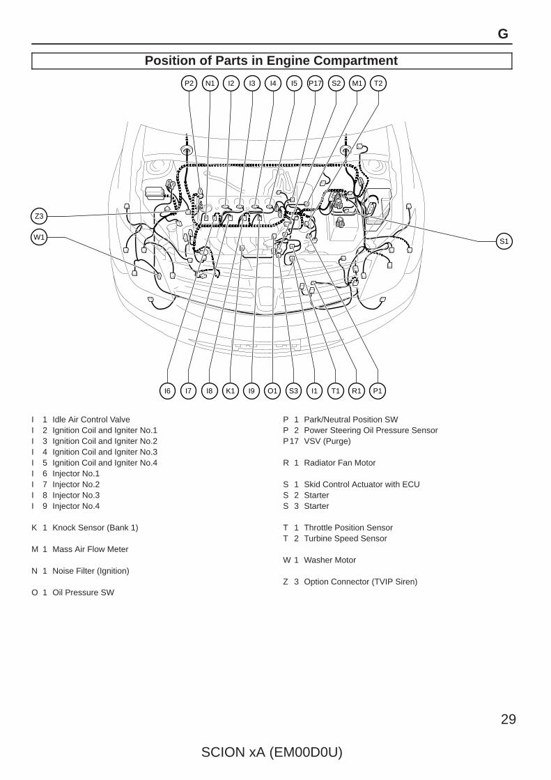
G ELECTRICAL WIRING ROUTING
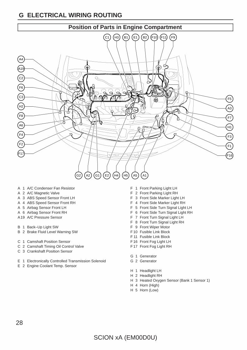
Position of Parts in Engine Compartment
C3
F6
C2
A4
A19
A6
H2
F8
F4
F2
F17
F5
A3
F7
H1
F3
F1
F16
C1 H3 B1 E1 B2 F10 F11 F9
E2G1A2G2 H5H4 A5 A1
A 1 A/C Condenser Fan ResistorA 2 A/C Magnetic ValveA 3 ABS Speed Sensor Front LHA 4 ABS Speed Sensor Front RHA 5 Airbag Sensor Front LHA 6 Airbag Sensor Front RHA19 A/C Pressure Sensor
B 1 Back–Up Light SWB 2 Brake Fluid Level Warning SW
C 1 Camshaft Position SensorC 2 Camshaft Timing Oil Control ValveC 3 Crankshaft Position Sensor
E 1 Electronically Controlled Transmission SolenoidE 2 Engine Coolant Temp. Sensor
F 1 Front Parking Light LHF 2 Front Parking Light RHF 3 Front Side Marker Light LHF 4 Front Side Marker Light RHF 5 Front Side Turn Signal Light LHF 6 Front Side Turn Signal Light RHF 7 Front Turn Signal Light LHF 8 Front Turn Signal Light RHF 9 Front Wiper MotorF 10 Fusible Link BlockF 11 Fusible Link BlockF 16 Front Fog Light LHF 17 Front Fog Light RH
G 1 GeneratorG 2 Generator
H 1 Headlight LHH 2 Headlight RHH 3 Heated Oxygen Sensor (Bank 1 Sensor 1)H 4 Horn (High)H 5 Horn (Low)
SCION xA (EM00D0U)
29
G
Position of Parts in Engine Compartment
Z3
W1 S1
P2 N1 I2 I3 I4 I5 P17 S2 M1 T2
I9K1I8I7I6 S3O1 I1 T1 R1 P1
I 1 Idle Air Control ValveI 2 Ignition Coil and Igniter No.1I 3 Ignition Coil and Igniter No.2I 4 Ignition Coil and Igniter No.3I 5 Ignition Coil and Igniter No.4I 6 Injector No.1I 7 Injector No.2I 8 Injector No.3I 9 Injector No.4
K 1 Knock Sensor (Bank 1)
M 1 Mass Air Flow Meter
N 1 Noise Filter (Ignition)
O 1 Oil Pressure SW
P 1 Park/Neutral Position SWP 2 Power Steering Oil Pressure SensorP17 VSV (Purge)
R 1 Radiator Fan Motor
S 1 Skid Control Actuator with ECUS 2 StarterS 3 Starter
T 1 Throttle Position SensorT 2 Turbine Speed Sensor
W 1 Washer Motor
Z 3 Option Connector (TVIP Siren)
30
SCION xA (EM00D0U)
G ELECTRICAL WIRING ROUTING
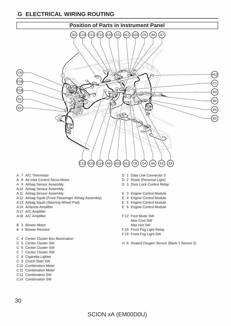
Position of Parts in Instrument Panel
D1
C9
F19
F18
D2
C7
B3
B4
A12
E6
E5
D3 C10 C11 F12 A14 A8 A7C5 A17 A18 C6
C14A13C12 A10A9 A11 C8 C4 H6 E3 E4
A 7 A/C ThermistorA 8 Air Inlet Control Servo MotorA 9 Airbag Sensor AssemblyA10 Airbag Sensor AssemblyA 11 Airbag Sensor AssemblyA12 Airbag Squib (Front Passenger Airbag Assembly)A13 Airbag Squib (Steering Wheel Pad)A14 Antenna AmplifierA17 A/C AmplifierA18 A/C Amplifier
B 3 Blower MotorB 4 Blower Resistor
C 4 Center Cluster Box IlluminationC 5 Center Cluster SWC 6 Center Cluster SWC 7 Center Cluster SWC 8 Cigarette LighterC 9 Clutch Start SWC10 Combination MeterC11 Combination MeterC12 Combination SWC14 Combination SW
D 1 Data Link Connector 3D 2 Diode (Personal Light)D 3 Door Lock Control Relay
E 3 Engine Control ModuleE 4 Engine Control ModuleE 5 Engine Control ModuleE 6 Engine Control Module
F 12 Foot Mode SWMax Cool SWMax Hot SW
F 18 Front Fog Light RelayF 19 Front Fog Light SW
H 6 Heated Oxygen Sensor (Bank 1 Sensor 2)

SCION xA (EM00D0U)
31
G
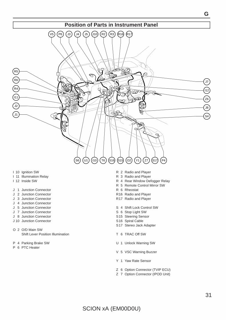
Position of Parts in Instrument Panel
R4
R6
R5
I11
J2
J1
J7
I12
Z6
J8
S4
J4J3V5 P6 J5 R2J10 R3 R16 R17
I10U1S6 S16 O2S15T6 Y1 P4Z7 S17
I 10 Ignition SWI 11 Illumination RelayI 12 Inside SW
J 1 Junction ConnectorJ 2 Junction ConnectorJ 3 Junction ConnectorJ 4 Junction ConnectorJ 5 Junction ConnectorJ 7 Junction ConnectorJ 8 Junction ConnectorJ 10 Junction Connector
O 2 O/D Main SWShift Lever Position Illumination
P 4 Parking Brake SWP 6 PTC Heater
R 2 Radio and PlayerR 3 Radio and PlayerR 4 Rear Window Defogger RelayR 5 Remote Control Mirror SWR 6 RheostatR16 Radio and PlayerR17 Radio and Player
S 4 Shift Lock Control SWS 6 Stop Light SWS15 Steering SensorS16 Spiral CableS17 Stereo Jack Adapter
T 6 TRAC Off SW
U 1 Unlock Warning SW
V 5 VSC Warning Buzzer
Y 1 Yaw Rate Sensor
Z 6 Option Connector (TVIP ECU)Z 7 Option Connector (IPOD Unit)
32
SCION xA (EM00D0U)
G ELECTRICAL WIRING ROUTING
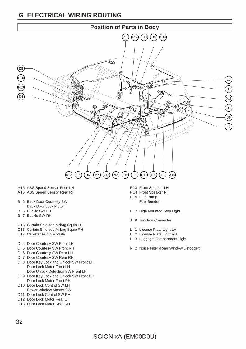
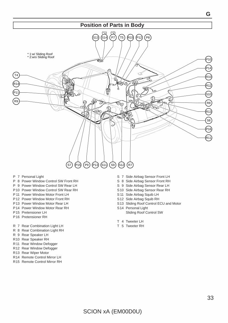
Position of Parts in Body
F13
D10
D8
D4
H7
D13
D7
L3
D5
L2
C15 D11 C16F14 D9
N2A15B7D6B6D12 J9 C17F15 B5 L1 A16
A15 ABS Speed Sensor Rear LHA16 ABS Speed Sensor Rear RH
B 5 Back Door Courtesy SWBack Door Lock Motor
B 6 Buckle SW LHB 7 Buckle SW RH
C15 Curtain Shielded Airbag Squib LHC16 Curtain Shielded Airbag Squib RHC17 Canister Pump Module
D 4 Door Courtesy SW Front LHD 5 Door Courtesy SW Front RHD 6 Door Courtesy SW Rear LHD 7 Door Courtesy SW Rear RHD 8 Door Key Lock and Unlock SW Front LH
Door Lock Motor Front LHDoor Unlock Detection SW Front LH
D 9 Door Key Lock and Unlock SW Front RHDoor Lock Motor Front RH
D10 Door Lock Control SW LHPower Window Master SW
D11 Door Lock Control SW RHD12 Door Lock Motor Rear LHD13 Door Lock Motor Rear RH
F 13 Front Speaker LHF 14 Front Speaker RHF 15 Fuel Pump
Fuel Sender
H 7 High Mounted Stop Light
J 9 Junction Connector
L 1 License Plate Light LHL 2 License Plate Light RHL 3 Luggage Compartment Light
N 2 Noise Filter (Rear Window Defogger)

SCION xA (EM00D0U)
33
G
Position of Parts in Body
P11
R14
T4
R9
R12
S10
R8
R10
P14
P10
R13
S8
P16
R11
P7
(*2)
* 1:w/ Sliding Roof* 2:w/o Sliding Roof
S14
(*1)
S13 T5 R15 P12 P8
S9S11P13P9P15S7 S12 R7
P 7 Personal LightP 8 Power Window Control SW Front RHP 9 Power Window Control SW Rear LHP10 Power Window Control SW Rear RHP 11 Power Window Motor Front LHP12 Power Window Motor Front RHP13 Power Window Motor Rear LHP14 Power Window Motor Rear RHP15 Pretensioner LHP16 Pretensioner RH
R 7 Rear Combination Light LHR 8 Rear Combination Light RHR 9 Rear Speaker LHR10 Rear Speaker RHR11 Rear Window DefoggerR12 Rear Window DefoggerR13 Rear Wiper MotorR14 Remote Control Mirror LHR15 Remote Control Mirror RH
S 7 Side Airbag Sensor Front LHS 8 Side Airbag Sensor Front RHS 9 Side Airbag Sensor Rear LHS10 Side Airbag Sensor Rear RHS 11 Side Airbag Squib LHS12 Side Airbag Squib RHS13 Sliding Roof Control ECU and MotorS14 Personal Light
Sliding Roof Control SW
T 4 Tweeter LHT 5 Tweeter RH
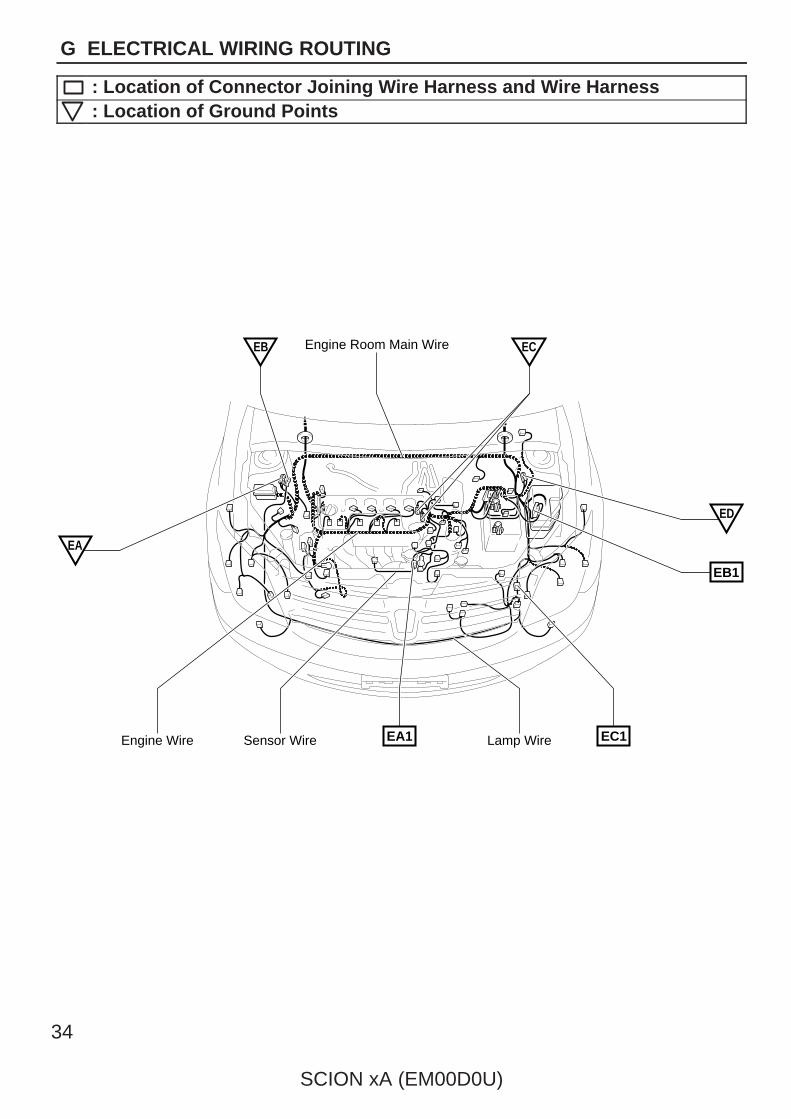
Engine Room Main Wire
EC1EA1
EB
EB1
ED
EA
Engine Wire Sensor Wire Lamp Wire
EC
34
SCION xA (EM00D0U)
G ELECTRICAL WIRING ROUTING
: Location of Connector Joining Wire Harness and Wire Harness: Location of Ground Points

SCION xA (EM00D0U)
35
Memo
36
SCION xA (EM00D0U)
G ELECTRICAL WIRING ROUTING
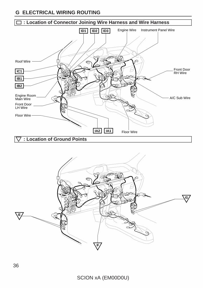
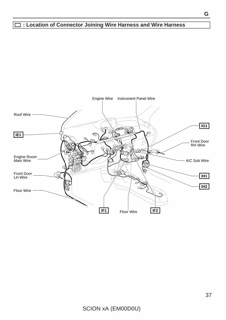
: Location of Connector Joining Wire Harness and Wire Harness
Instrument Panel WireEngine Wire
Front DoorRH Wire
A/C Sub Wire
ID2 ID3ID1
Floor Wire
IC1
IB1
IB2
Roof Wire
Floor Wire
Engine RoomMain Wire
Front DoorLH Wire
IA2 IA1
: Location of Ground Points
IF
IE
IG
Instrument Panel WireEngine Wire
Front DoorRH Wire
A/C Sub Wire
Roof Wire
Engine RoomMain Wire
Front DoorLH Wire
Floor Wire
IF1 IF2
IH2
IH1
IG1
Floor Wire
IE1
SCION xA (EM00D0U)
37
G
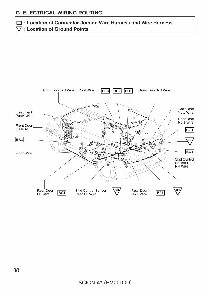
: Location of Connector Joining Wire Harness and Wire Harness

Rear Door RH Wire
Skid Control SensorRear LH Wire
Front Door RH Wire Roof Wire
Rear DoorNo.1 Wire
Back DoorNo.1 Wire
Skid ControlSensor RearRH Wire
Rear DoorLH Wire
Front DoorLH Wire
Floor Wire
InstrumentPanel Wire
BE3 BE2 BB1
BC1 BF1
BG1
BD1
BI
Rear DoorNo.1 Wire
BA1
BH BJ
38
SCION xA (EM00D0U)
G ELECTRICAL WIRING ROUTING
: Location of Connector Joining Wire Harness and Wire Harness: Location of Ground Points

SCION xA (EM00D0U)
39
Memo
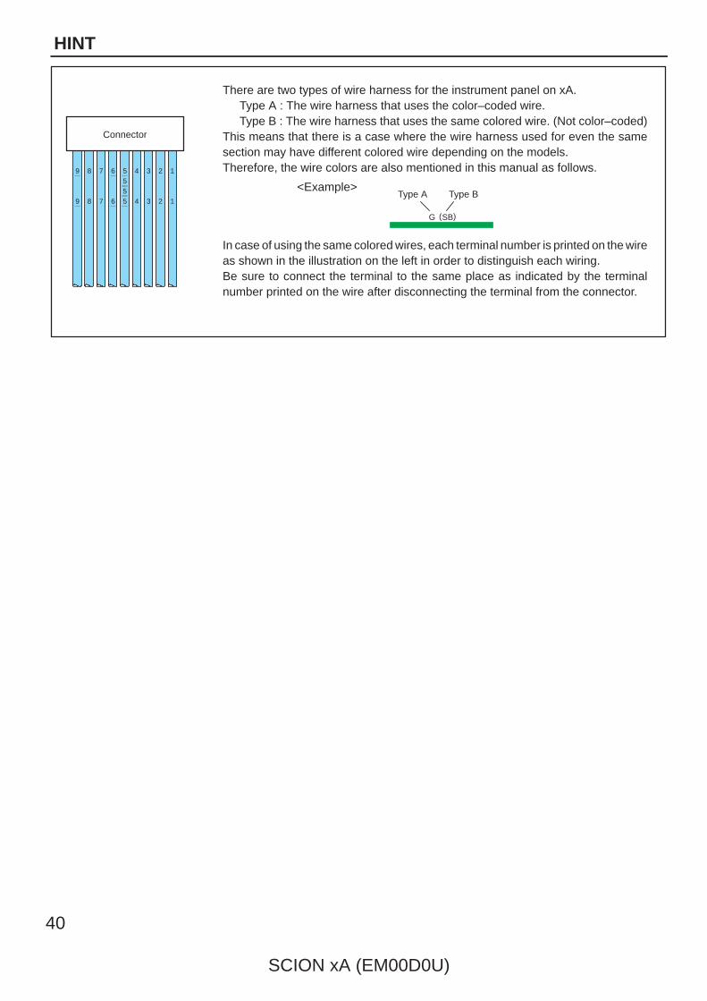
There are two types of wire harness for the instrument panel on xA.Type A : The wire harness that uses the color–coded wire.Type B : The wire harness that uses the same colored wire. (Not color–coded)
This means that there is a case where the wire harness used for even the samesection may have different colored wire depending on the models.Therefore, the wire colors are also mentioned in this manual as follows.
In case of using the same colored wires, each terminal number is printed on the wireas shown in the illustration on the left in order to distinguish each wiring.Be sure to connect the terminal to the same place as indicated by the terminalnumber printed on the wire after disconnecting the terminal from the connector.
1234678
123467
9
9 8
5555
Connector
SBG ( )
<Example>Type A Type B
40
SCION xA (EM00D0U)
HINT
28
SCION xA (EM00D0U)
G ELECTRICAL WIRING ROUTING
Position of Parts in Engine Compartment
C3
F6
C2
A4
A19
A6
H2
F8
F4
F2
F17
F5
A3
F7
H1
F3
F1
F16
C1 H3 B1 E1 B2 F10 F11 F9
E2G1A2G2 H5H4 A5 A1
A 1 A/C Condenser Fan ResistorA 2 A/C Magnetic ValveA 3 ABS Speed Sensor Front LHA 4 ABS Speed Sensor Front RHA 5 Airbag Sensor Front LHA 6 Airbag Sensor Front RHA19 A/C Pressure Sensor
B 1 Back–Up Light SWB 2 Brake Fluid Level Warning SW
C 1 Camshaft Position SensorC 2 Camshaft Timing Oil Control ValveC 3 Crankshaft Position Sensor
E 1 Electronically Controlled Transmission SolenoidE 2 Engine Coolant Temp. Sensor
F 1 Front Parking Light LHF 2 Front Parking Light RHF 3 Front Side Marker Light LHF 4 Front Side Marker Light RHF 5 Front Side Turn Signal Light LHF 6 Front Side Turn Signal Light RHF 7 Front Turn Signal Light LHF 8 Front Turn Signal Light RHF 9 Front Wiper MotorF 10 Fusible Link BlockF 11 Fusible Link BlockF 16 Front Fog Light LHF 17 Front Fog Light RH
G 1 GeneratorG 2 Generator
H 1 Headlight LHH 2 Headlight RHH 3 Heated Oxygen Sensor (Bank 1 Sensor 1)H 4 Horn (High)H 5 Horn (Low)

SCION xA (EM00D0U)
29
G
Position of Parts in Engine Compartment
Z3
W1 S1
P2 N1 I2 I3 I4 I5 P17 S2 M1 T2
I9K1I8I7I6 S3O1 I1 T1 R1 P1
I 1 Idle Air Control ValveI 2 Ignition Coil and Igniter No.1I 3 Ignition Coil and Igniter No.2I 4 Ignition Coil and Igniter No.3I 5 Ignition Coil and Igniter No.4I 6 Injector No.1I 7 Injector No.2I 8 Injector No.3I 9 Injector No.4
K 1 Knock Sensor (Bank 1)
M 1 Mass Air Flow Meter
N 1 Noise Filter (Ignition)
O 1 Oil Pressure SW
P 1 Park/Neutral Position SWP 2 Power Steering Oil Pressure SensorP17 VSV (Purge)
R 1 Radiator Fan Motor
S 1 Skid Control Actuator with ECUS 2 StarterS 3 Starter
T 1 Throttle Position SensorT 2 Turbine Speed Sensor
W 1 Washer Motor
Z 3 Option Connector (TVIP Siren)

30
SCION xA (EM00D0U)
G ELECTRICAL WIRING ROUTING
Position of Parts in Instrument Panel
D1
C9
F19
F18
D2
C7
B3
B4
A12
E6
E5
D3 C10 C11 F12 A14 A8 A7C5 A17 A18 C6
C14A13C12 A10A9 A11 C8 C4 H6 E3 E4
A 7 A/C ThermistorA 8 Air Inlet Control Servo MotorA 9 Airbag Sensor AssemblyA10 Airbag Sensor AssemblyA 11 Airbag Sensor AssemblyA12 Airbag Squib (Front Passenger Airbag Assembly)A13 Airbag Squib (Steering Wheel Pad)A14 Antenna AmplifierA17 A/C AmplifierA18 A/C Amplifier
B 3 Blower MotorB 4 Blower Resistor
C 4 Center Cluster Box IlluminationC 5 Center Cluster SWC 6 Center Cluster SWC 7 Center Cluster SWC 8 Cigarette LighterC 9 Clutch Start SWC10 Combination MeterC11 Combination MeterC12 Combination SWC14 Combination SW
D 1 Data Link Connector 3D 2 Diode (Personal Light)D 3 Door Lock Control Relay
E 3 Engine Control ModuleE 4 Engine Control ModuleE 5 Engine Control ModuleE 6 Engine Control Module
F 12 Foot Mode SWMax Cool SWMax Hot SW
F 18 Front Fog Light RelayF 19 Front Fog Light SW
H 6 Heated Oxygen Sensor (Bank 1 Sensor 2)
SCION xA (EM00D0U)
31
G
Position of Parts in Instrument Panel
R4
R6
R5
I11
J2
J1
J7
I12
Z6
J8
S4
J4J3V5 P6 J5 R2J10 R3 R16 R17
I10U1S6 S16 O2S15T6 Y1 P4Z7 S17
I 10 Ignition SWI 11 Illumination RelayI 12 Inside SW
J 1 Junction ConnectorJ 2 Junction ConnectorJ 3 Junction ConnectorJ 4 Junction ConnectorJ 5 Junction ConnectorJ 7 Junction ConnectorJ 8 Junction ConnectorJ 10 Junction Connector
O 2 O/D Main SWShift Lever Position Illumination
P 4 Parking Brake SWP 6 PTC Heater
R 2 Radio and PlayerR 3 Radio and PlayerR 4 Rear Window Defogger RelayR 5 Remote Control Mirror SWR 6 RheostatR16 Radio and PlayerR17 Radio and Player
S 4 Shift Lock Control SWS 6 Stop Light SWS15 Steering SensorS16 Spiral CableS17 Stereo Jack Adapter
T 6 TRAC Off SW
U 1 Unlock Warning SW
V 5 VSC Warning Buzzer
Y 1 Yaw Rate Sensor
Z 6 Option Connector (TVIP ECU)Z 7 Option Connector (IPOD Unit)

32
SCION xA (EM00D0U)
G ELECTRICAL WIRING ROUTING
Position of Parts in Body
F13
D10
D8
D4
H7
D13
D7
L3
D5
L2
C15 D11 C16F14 D9
N2A15B7D6B6D12 J9 C17F15 B5 L1 A16
A15 ABS Speed Sensor Rear LHA16 ABS Speed Sensor Rear RH
B 5 Back Door Courtesy SWBack Door Lock Motor
B 6 Buckle SW LHB 7 Buckle SW RH
C15 Curtain Shielded Airbag Squib LHC16 Curtain Shielded Airbag Squib RHC17 Canister Pump Module
D 4 Door Courtesy SW Front LHD 5 Door Courtesy SW Front RHD 6 Door Courtesy SW Rear LHD 7 Door Courtesy SW Rear RHD 8 Door Key Lock and Unlock SW Front LH
Door Lock Motor Front LHDoor Unlock Detection SW Front LH
D 9 Door Key Lock and Unlock SW Front RHDoor Lock Motor Front RH
D10 Door Lock Control SW LHPower Window Master SW
D11 Door Lock Control SW RHD12 Door Lock Motor Rear LHD13 Door Lock Motor Rear RH
F 13 Front Speaker LHF 14 Front Speaker RHF 15 Fuel Pump
Fuel Sender
H 7 High Mounted Stop Light
J 9 Junction Connector
L 1 License Plate Light LHL 2 License Plate Light RHL 3 Luggage Compartment Light
N 2 Noise Filter (Rear Window Defogger)
SCION xA (EM00D0U)
33
G
Position of Parts in Body
P11
R14
T4
R9
R12
S10
R8
R10
P14
P10
R13
S8
P16
R11
P7
(*2)
* 1:w/ Sliding Roof* 2:w/o Sliding Roof
S14
(*1)
S13 T5 R15 P12 P8
S9S11P13P9P15S7 S12 R7
P 7 Personal LightP 8 Power Window Control SW Front RHP 9 Power Window Control SW Rear LHP10 Power Window Control SW Rear RHP 11 Power Window Motor Front LHP12 Power Window Motor Front RHP13 Power Window Motor Rear LHP14 Power Window Motor Rear RHP15 Pretensioner LHP16 Pretensioner RH
R 7 Rear Combination Light LHR 8 Rear Combination Light RHR 9 Rear Speaker LHR10 Rear Speaker RHR11 Rear Window DefoggerR12 Rear Window DefoggerR13 Rear Wiper MotorR14 Remote Control Mirror LHR15 Remote Control Mirror RH
S 7 Side Airbag Sensor Front LHS 8 Side Airbag Sensor Front RHS 9 Side Airbag Sensor Rear LHS10 Side Airbag Sensor Rear RHS 11 Side Airbag Squib LHS12 Side Airbag Squib RHS13 Sliding Roof Control ECU and MotorS14 Personal Light
Sliding Roof Control SW
T 4 Tweeter LHT 5 Tweeter RH

Engine Room Main Wire
EC1EA1
EB
EB1
ED
EA
Engine Wire Sensor Wire Lamp Wire
EC
34
SCION xA (EM00D0U)
G ELECTRICAL WIRING ROUTING
: Location of Connector Joining Wire Harness and Wire Harness: Location of Ground Points

SCION xA (EM00D0U)
35
Memo

36
SCION xA (EM00D0U)
G ELECTRICAL WIRING ROUTING
: Location of Connector Joining Wire Harness and Wire Harness
Instrument Panel WireEngine Wire
Front DoorRH Wire
A/C Sub Wire
ID2 ID3ID1
Floor Wire
IC1
IB1
IB2
Roof Wire
Floor Wire
Engine RoomMain Wire
Front DoorLH Wire
IA2 IA1
: Location of Ground Points
IF
IE
IG

Instrument Panel WireEngine Wire
Front DoorRH Wire
A/C Sub Wire
Roof Wire
Engine RoomMain Wire
Front DoorLH Wire
Floor Wire
IF1 IF2
IH2
IH1
IG1
Floor Wire
IE1
SCION xA (EM00D0U)
37
G
: Location of Connector Joining Wire Harness and Wire Harness
Rear Door RH Wire
Skid Control SensorRear LH Wire
Front Door RH Wire Roof Wire
Rear DoorNo.1 Wire
Back DoorNo.1 Wire
Skid ControlSensor RearRH Wire
Rear DoorLH Wire
Front DoorLH Wire
Floor Wire
InstrumentPanel Wire
BE3 BE2 BB1
BC1 BF1
BG1
BD1
BI
Rear DoorNo.1 Wire
BA1
BH BJ
38
SCION xA (EM00D0U)
G ELECTRICAL WIRING ROUTING
: Location of Connector Joining Wire Harness and Wire Harness: Location of Ground Points

SCION xA (EM00D0U)
39
Memo

There are two types of wire harness for the instrument panel on xA.Type A : The wire harness that uses the color–coded wire.Type B : The wire harness that uses the same colored wire. (Not color–coded)
This means that there is a case where the wire harness used for even the samesection may have different colored wire depending on the models.Therefore, the wire colors are also mentioned in this manual as follows.
In case of using the same colored wires, each terminal number is printed on the wireas shown in the illustration on the left in order to distinguish each wiring.Be sure to connect the terminal to the same place as indicated by the terminalnumber printed on the wire after disconnecting the terminal from the connector.
1234678
123467
9
9 8
5555
Connector
SBG ( )
<Example>Type A Type B
40
SCION xA (EM00D0U)
HINT
42
SCION xA (EM00D0U)
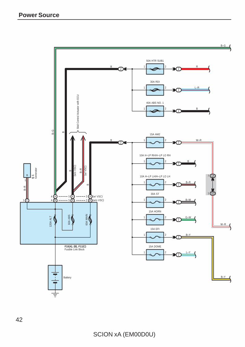
Power Source
60A
MA
IN
60A
AB
S
120A
ALT
C1 B4
1 2
15A EFI
1 2
15A HORN
30A ST
21
1 2
10A H–LP LH/H–LP LO LH
1 2
10A H–LP RH/H–LP LO RH
1 2
15A AM2
2
1 2
50A HTR SUB1
2
2
1 1O
7 1A
Battery
1
B
B–R
B
B
B
B–G
B–G
W–R
W–R
G 1
B5
2
2
2
2
2
B
B–R
B–W
G–W
B–Y
2R
1 2
30A RDI
2L–R
B
F10(A), (B), F11(C)
1 2
40A ABS NO. 1
2B
B2 (w/o VSC)A3 (w/ VSC)
B–Y
1 2
15A DOME
2L–Y
Fusible Link Block
Gen
erat
or
A5A4
Ski
d C
ontro
l Act
uato
r w
ith E
CU
B
( w/o
VS
C)
B–R
( w/ V
SC
)
SCION xA (EM00D0U)
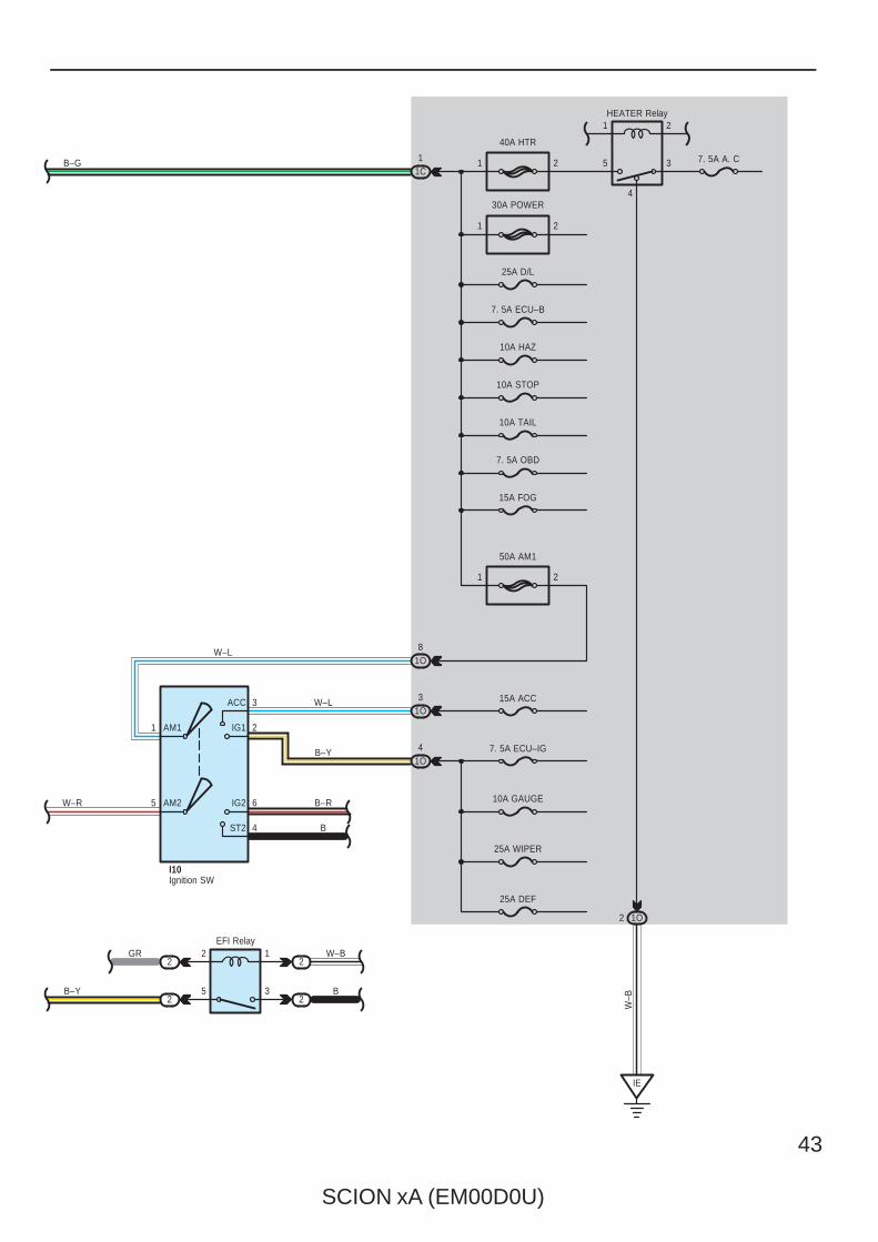
43
1C1 1 2
40A HTR
1 2
30A POWER
25A D/L
7. 5A ECU–B
10A HAZ
10A TAIL
7. 5A OBD
1 2
50A AM1
1O8
15A ACC
7. 5A ECU–IG
1O3
1O4
1
5
3
2
6
4
AM2
AM1
ACC
IG1
IG2
ST2
10A GAUGE
25A WIPER
W–B
1
5
2
3
4
7. 5A A. C
IE
1O2
10A STOP
B–G
W–R
HEATER Relay
W–L
W–L
B–Y
B–R
B
I10
15A FOG
2
5
1
3
2
2
2
2B–Y
GR W–B
B
EFI Relay
Ignition SW
25A DEF
44
SCION xA (EM00D0U)
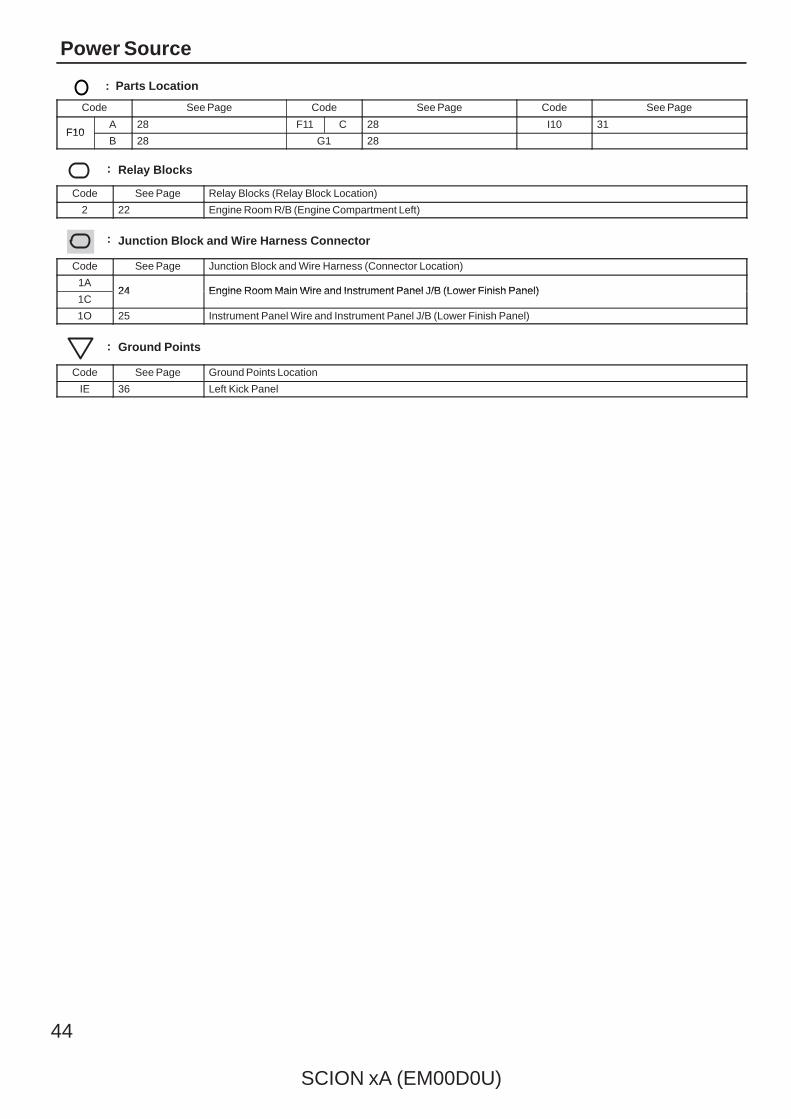
Power Source
: Parts Location
Code See Page Code See Page Code See Page
F10A 28 F11 C 28 I10 31
F10B 28 G1 28
: Relay Blocks
Code See Page Relay Blocks (Relay Block Location)
2 22 Engine Room R/B (Engine Compartment Left)
: Junction Block and Wire Harness Connector
Code See Page Junction Block and Wire Harness (Connector Location)
1A24 Engine Room Main Wire and Instrument Panel J/B (Lower Finish Panel)
1C24 Engine Room Main Wire and Instrument Panel J/B (Lower Finish Panel)
1O 25 Instrument Panel Wire and Instrument Panel J/B (Lower Finish Panel)
: Ground Points
Code See Page Ground Points Location
IE 36 Left Kick Panel

SCION xA (EM00D0U)
45
Memo
46
SCION xA (EM00D0U)
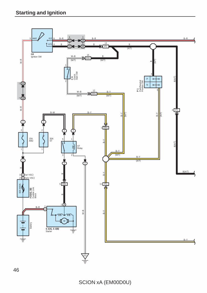
Starting and Ignition60
A M
AIN
2
2
1
2
15AAM2
30AST
2
2
1O1
1A7
51A3
1O6
1E6
1O7
1
15
23
M
B1
B
A1
EB15
2
ED
2
P
N
4
B
5
B–R
B(A/T)
B–W
STRelay
BB
B–R
W–B
W–R
W–R
B–R
B
B–R
(A/T)
B–Y
B–Y
( M/T
)
B–Y
( A/T
)
P 1
B–Y
F10(
A), (
B)
6
4
AM2 IG2
ST2
I10
Bat
tery
12
1
2
EB1
(M/T)
C 9
W–B
(M/T)
B
B–YW–B
(M/T) (M/T)
EB115
B
B
( A/T
)
(A/T)
IF213
S 2(A), S 3(B)
Clu
tch
Sta
rt S
W
Fusi
ble
Link
Blo
ck
Ignition SW
Par
k/N
eutra
lP
ositi
on S
W
Starter
IF14
B( A
/T)
B( A
/T)
B–Y
(M/T)
B–Y
EB11
IF111
B–Y
B–Y
B–Y
2 2
(w/o VSC)B2(w/ VSC)A3
SCION xA (EM00D0U)
47
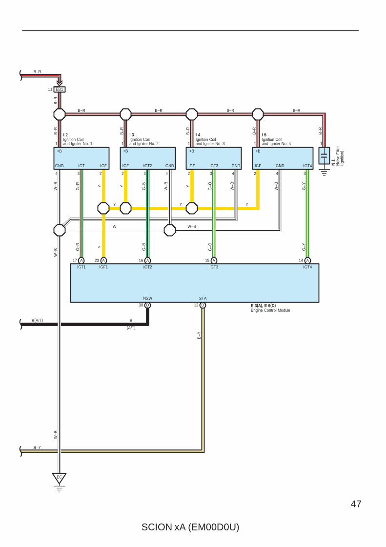
EB111
A23A17
EC
1
4 3 2
I 2
1
2 3 4
I 3
1
2 3 4
I 4
1
2 4 3
I 5
A16 A15 A14
D12
1
B–Y
B–Y
B–R
B–R B–R B–R
Y Y
W–B
B–R
B–R
B–R
B–R
Y
G–B
W–B Y
G–O
W–B
W–B
G–Y
G–O
G–B
G–Y
N 1
STA
IGT2 IGT3 IGT4
B–R
B–R
Y
G–R
W–B
Y
W
Y
G–R
W–B
IGT1 IGF1
W–B
B–R
D30
NSW
B(A/T)
E 3(A), E 6(D)
B
(A/T)
GND IGT IGF
+B
IGF IGT2 GND
+B
IGF IGT3 GND
+B
IGF GND IGT4
+B
Engine Control Module
Ignition Coiland Igniter No. 1
Ignition Coiland Igniter No. 2
Ignition Coiland Igniter No. 3
Ignition Coiland Igniter No. 4
Noi
se F
ilter
( Igni
tion)

48
SCION xA (EM00D0U)
Starting and Ignition
: Parts Location
Code See Page Code See Page Code See Page
C9 30 I2 29 N1 29
E3 A 30 I3 29 P1 29
E6 D 30 I4 29 S2 A 29
F10 A 28 I5 29 S3 B 29
F10 B 28 I10 31
: Relay Blocks
Code See Page Relay Blocks (Relay Block Location)
2 22 Engine Room R/B (Engine Compartment Left)
: Junction Block and Wire Harness Connector
Code See Page Junction Block and Wire Harness (Connector Location)
1A 24 Engine Room Main Wire and Instrument Panel J/B (Lower Finish Panel)
1E25 Instrument Panel Wire and Instrument Panel J/B (Lower Finish Panel)
1O25 Instrument Panel Wire and Instrument Panel J/B (Lower Finish Panel)
: Connector Joining Wire Harness and Wire Harness
Code See Page Joining Wire Harness and Wire Harness (Connector Location)
EB1 34 Engine Wire and Engine Room Main Wire (Inside of the Engine Room R/B)
IF137 Engine Wire and Instrument Panel Wire (Left Side of the Blower Unit)
IF237 Engine Wire and Instrument Panel Wire (Left Side of the Blower Unit)
: Ground Points
Code See Page Ground Points Location
EC 34 Cylinder Head
ED 34 Front Fender Apron LH

SCION xA (EM00D0U)
49
Memo

SCION xA (EM00D0U)
41
SYSTEM CIRCUITS H
2006 xAELECTRICAL WIRING DIAGRAM
SYSTEM CIRCUITSPage
ABS (w/ VSC) . . . . . . . . . . . . . . . . . . . . . . . . . . . . . . . . . . . . . . . . . . . . . . . . . . . . . . . 96ABS (w/o VSC) . . . . . . . . . . . . . . . . . . . . . . . . . . . . . . . . . . . . . . . . . . . . . . . . . . . . . 106Air Conditioning . . . . . . . . . . . . . . . . . . . . . . . . . . . . . . . . . . . . . . . . . . . . . . . . . . . . 150Audio System . . . . . . . . . . . . . . . . . . . . . . . . . . . . . . . . . . . . . . . . . . . . . . . . . . . . . . 132Back–Up Light . . . . . . . . . . . . . . . . . . . . . . . . . . . . . . . . . . . . . . . . . . . . . . . . . . . . . . 76Charging . . . . . . . . . . . . . . . . . . . . . . . . . . . . . . . . . . . . . . . . . . . . . . . . . . . . . . . . . . . 50Cigarette Lighter . . . . . . . . . . . . . . . . . . . . . . . . . . . . . . . . . . . . . . . . . . . . . . . . . . . . 126Combination Meter . . . . . . . . . . . . . . . . . . . . . . . . . . . . . . . . . . . . . . . . . . . . . . . . . . 136Door Lock Control . . . . . . . . . . . . . . . . . . . . . . . . . . . . . . . . . . . . . . . . . . . . . . . . . . 86Electronically Controlled Transmission and A/T Indicator . . . . . . . . . . . . . . 90Engine Control . . . . . . . . . . . . . . . . . . . . . . . . . . . . . . . . . . . . . . . . . . . . . . . . . . . . . 52Front Fog Light . . . . . . . . . . . . . . . . . . . . . . . . . . . . . . . . . . . . . . . . . . . . . . . . . . . . . 62Front Wiper and Washer . . . . . . . . . . . . . . . . . . . . . . . . . . . . . . . . . . . . . . . . . . . . . 78Headlight . . . . . . . . . . . . . . . . . . . . . . . . . . . . . . . . . . . . . . . . . . . . . . . . . . . . . . . . . . 60Horn . . . . . . . . . . . . . . . . . . . . . . . . . . . . . . . . . . . . . . . . . . . . . . . . . . . . . . . . . . . . . . . 128Ignition . . . . . . . . . . . . . . . . . . . . . . . . . . . . . . . . . . . . . . . . . . . . . . . . . . . . . . . . . . . . 46Illumination . . . . . . . . . . . . . . . . . . . . . . . . . . . . . . . . . . . . . . . . . . . . . . . . . . . . . . . . 70Interior Light . . . . . . . . . . . . . . . . . . . . . . . . . . . . . . . . . . . . . . . . . . . . . . . . . . . . . . . 68Key Reminder . . . . . . . . . . . . . . . . . . . . . . . . . . . . . . . . . . . . . . . . . . . . . . . . . . . . . . 120Light Reminder . . . . . . . . . . . . . . . . . . . . . . . . . . . . . . . . . . . . . . . . . . . . . . . . . . . . . 122Multiplex Communication System (CAN) . . . . . . . . . . . . . . . . . . . . . . . . . . . . . . 104Power Source . . . . . . . . . . . . . . . . . . . . . . . . . . . . . . . . . . . . . . . . . . . . . . . . . . . . . . 42Power Window . . . . . . . . . . . . . . . . . . . . . . . . . . . . . . . . . . . . . . . . . . . . . . . . . . . . . 82PTC Heater . . . . . . . . . . . . . . . . . . . . . . . . . . . . . . . . . . . . . . . . . . . . . . . . . . . . . . . . . 146Radiator Fan and Condenser Fan . . . . . . . . . . . . . . . . . . . . . . . . . . . . . . . . . . . . 148Rear Window Defogger . . . . . . . . . . . . . . . . . . . . . . . . . . . . . . . . . . . . . . . . . . . . . . 130Rear Wiper and Washer . . . . . . . . . . . . . . . . . . . . . . . . . . . . . . . . . . . . . . . . . . . . . 80Remote Control Mirror . . . . . . . . . . . . . . . . . . . . . . . . . . . . . . . . . . . . . . . . . . . . . . 124Seat Belt Warning . . . . . . . . . . . . . . . . . . . . . . . . . . . . . . . . . . . . . . . . . . . . . . . . . . . 120Shift Lock . . . . . . . . . . . . . . . . . . . . . . . . . . . . . . . . . . . . . . . . . . . . . . . . . . . . . . . . . . 118Sliding Roof . . . . . . . . . . . . . . . . . . . . . . . . . . . . . . . . . . . . . . . . . . . . . . . . . . . . . . . . 114SRS . . . . . . . . . . . . . . . . . . . . . . . . . . . . . . . . . . . . . . . . . . . . . . . . . . . . . . . . . . . . . . . 109Starting . . . . . . . . . . . . . . . . . . . . . . . . . . . . . . . . . . . . . . . . . . . . . . . . . . . . . . . . . . . . 46Stop Light . . . . . . . . . . . . . . . . . . . . . . . . . . . . . . . . . . . . . . . . . . . . . . . . . . . . . . . . . . 74Taillight . . . . . . . . . . . . . . . . . . . . . . . . . . . . . . . . . . . . . . . . . . . . . . . . . . . . . . . . . . . . 70TRAC . . . . . . . . . . . . . . . . . . . . . . . . . . . . . . . . . . . . . . . . . . . . . . . . . . . . . . . . . . . . . . 96Turn Signal and Hazard Warning Light . . . . . . . . . . . . . . . . . . . . . . . . . . . . . . . . 64Two Way Flow Heater . . . . . . . . . . . . . . . . . . . . . . . . . . . . . . . . . . . . . . . . . . . . . . . 142VSC . . . . . . . . . . . . . . . . . . . . . . . . . . . . . . . . . . . . . . . . . . . . . . . . . . . . . . . . . . . . . . . 96

50
SCION xA (EM00D0U)
Charging
LBP
F
3 B
IG
2 B
5 1E
10AGAUGE
60A
MA
IN
15AAM2
2
1
2
2
7 1A
1 1O
1 B1
24
A
10 1E
9 1G
IF2
M
IC Regulator
8 1G
6 1O
L
R–B
B–R
B–R
Y
10
IF24
E
B–W
B–R
C1
Battery
B–R
W–R
W–R
B
Y
R–B
L
L
L
5 6
I10
B L IG M
9
E
AM2 IG2
ST2
G 1(A), G 2(B)
IF211
F10(
A), (
B), F
11( C
)
120A
ALT
Cha
rge
13
32
C11
Com
bina
tion
Met
er
Fusi
ble
Link
Blo
ck
Generator
Ignition SW
Eng
ine
Con
trol
Mod
ule
E 3
B2 (w/o VSC)A
/C A
mpl
ifier
A18
A3 (w/ VSC)
(IG)
ALTALT

SCION xA (EM00D0U)
51
: Parts Location
Code See Page Code See Page Code See Page
A18 30F10
A 28 G1 A 28
C11 30F10
B 28 G2 B 28
E3 30 F11 C 28 I10 31
: Relay Blocks
Code See Page Relay Blocks (Relay Block Location)
2 22 Engine Room R/B (Engine Compartment Left)
: Junction Block and Wire Harness Connector
Code See Page Junction Block and Wire Harness (Connector Location)
1A 24 Engine Room Main Wire and Instrument Panel J/B (Lower Finish Panel)
1E
25 Instrument Panel Wire and Instrument Panel J/B (Lower Finish Panel)1G 25 Instrument Panel Wire and Instrument Panel J/B (Lower Finish Panel)
1O
25 Instrument Panel Wire and Instrument Panel J/B (Lower Finish Panel)
: Connector Joining Wire Harness and Wire Harness
Code See Page Joining Wire Harness and Wire Harness (Connector Location)
IF2 37 Engine Wire and Instrument Panel Wire (Left Side of the Blower Unit)
78
SCION xA (EM00D0U)
Front Wiper and Washer
MIS
T
OFF INT
LO HI
OFF ON
25AWIPER
1N71A2 1A5
ID310
2
ED
ID317ID318ID39
M
11 1N
1O2
IE
4 1 3 2
W
EW
+S
+1
+2
+B
4
5
6
7
9
8
5
L–W
W–G
L–W
L–W
L–W
G
W–B
W–B
W–B
L–Y
L–B
W–G
L–W
L–Y
L–B
W–G
W–B
G
Washer SW
Front Wiper SW
Wiper Relay
W 1
+2 +1 +S B
E
F 9
C14
L–W
Combination SW
Front Wiper Motor
Was
her
Mot
or
(IG)
M
1
SCION xA (EM00D0U)
79
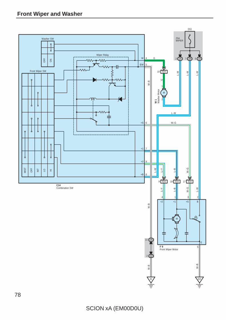
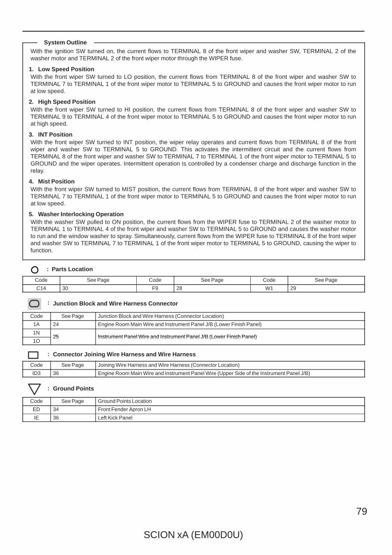
With the ignition SW turned on, the current flows to TERMINAL 8 of the front wiper and washer SW, TERMINAL 2 of thewasher motor and TERMINAL 2 of the front wiper motor through the WIPER fuse.
1. Low Speed PositionWith the front wiper SW turned to LO position, the current flows from TERMINAL 8 of the front wiper and washer SW toTERMINAL 7 to TERMINAL 1 of the front wiper motor to TERMINAL 5 to GROUND and causes the front wiper motor to runat low speed.
2. High Speed PositionWith the front wiper SW turned to HI position, the current flows from TERMINAL 8 of the front wiper and washer SW toTERMINAL 9 to TERMINAL 4 of the front wiper motor to TERMINAL 5 to GROUND and causes the front wiper motor to runat high speed.
3. INT PositionWith the front wiper SW turned to INT position, the wiper relay operates and current flows from TERMINAL 8 of the frontwiper and washer SW to TERMINAL 5 to GROUND. This activates the intermittent circuit and the current flows fromTERMINAL 8 of the front wiper and washer SW to TERMINAL 7 to TERMINAL 1 of the front wiper motor to TERMINAL 5 toGROUND and the wiper operates. Intermittent operation is controlled by a condenser charge and discharge function in therelay.
4. Mist PositionWith the front wiper SW turned to MIST position, the current flows from TERMINAL 8 of the front wiper and washer SW toTERMINAL 7 to TERMINAL 1 of the front wiper motor to TERMINAL 5 to GROUND and causes the front wiper motor to runat low speed.
5. Washer Interlocking OperationWith the washer SW pulled to ON position, the current flows from the WIPER fuse to TERMINAL 2 of the washer motor toTERMINAL 1 to TERMINAL 4 of the front wiper and washer SW to TERMINAL 5 to GROUND and causes the washer motorto run and the window washer to spray. Simultaneously, current flows from the WIPER fuse to TERMINAL 8 of the front wiperand washer SW to TERMINAL 7 to TERMINAL 1 of the front wiper motor to TERMINAL 5 to GROUND, causing the wiper tofunction.
: Parts Location
Code See Page Code See Page Code See Page
C14 30 F9 28 W1 29
: Junction Block and Wire Harness Connector
Code See Page Junction Block and Wire Harness (Connector Location)
1A 24 Engine Room Main Wire and Instrument Panel J/B (Lower Finish Panel)
1N25 Instrument Panel Wire and Instrument Panel J/B (Lower Finish Panel)
1O25 Instrument Panel Wire and Instrument Panel J/B (Lower Finish Panel)
: Connector Joining Wire Harness and Wire Harness
Code See Page Joining Wire Harness and Wire Harness (Connector Location)
ID3 36 Engine Room Main Wire and Instrument Panel Wire (Upper Side of the Instrument Panel J/B)
: Ground Points
Code See Page Ground Points Location
ED 34 Front Fender Apron LH
IE 36 Left Kick Panel
System Outline
80
SCION xA (EM00D0U)
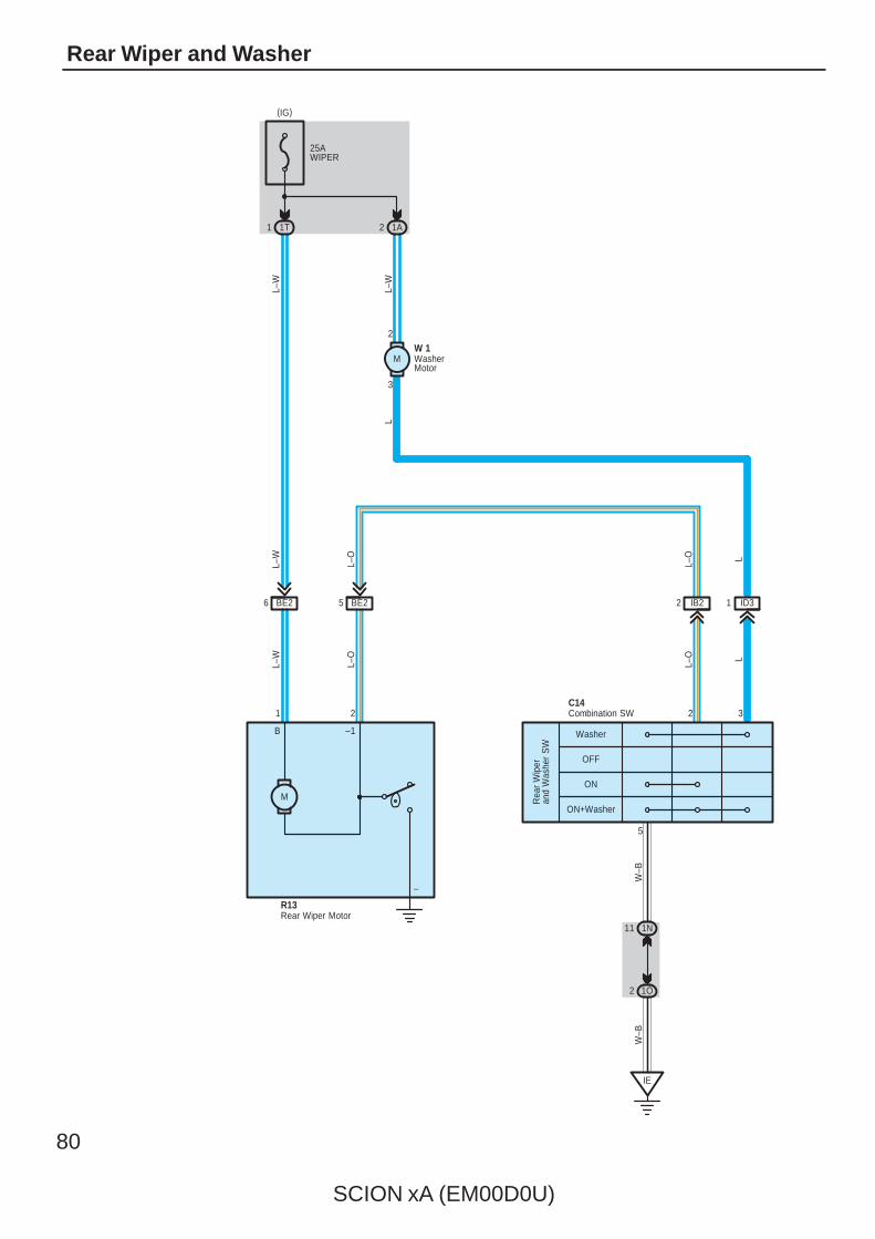
Rear Wiper and Washer
–
–1B
L–O
L–W
L–O
L–W
21
25AWIPER
1T1 1A2
3
2
1 ID3
ON+Washer
ON
OFF
Washer
2 IB2
W–B
5
C14
R13
11 1N
1O2
IE
6 BE2
2 3
5 BE2
M
L–W
L–W
Rea
r W
iper
and
Was
her
SW
W–B
L–O L
L–O L
L
W 1
Combination SW
Rear Wiper Motor
WasherMotor
(IG)
M
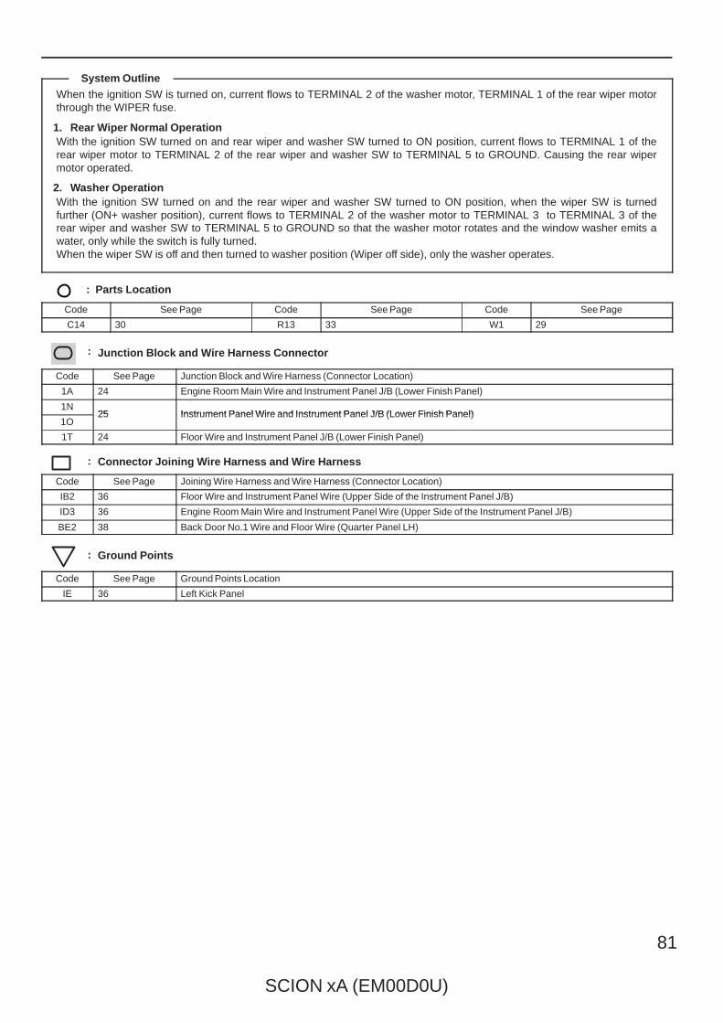
SCION xA (EM00D0U)
81
When the ignition SW is turned on, current flows to TERMINAL 2 of the washer motor, TERMINAL 1 of the rear wiper motorthrough the WIPER fuse.
1. Rear Wiper Normal OperationWith the ignition SW turned on and rear wiper and washer SW turned to ON position, current flows to TERMINAL 1 of therear wiper motor to TERMINAL 2 of the rear wiper and washer SW to TERMINAL 5 to GROUND. Causing the rear wipermotor operated.
2. Washer OperationWith the ignition SW turned on and the rear wiper and washer SW turned to ON position, when the wiper SW is turnedfurther (ON+ washer position), current flows to TERMINAL 2 of the washer motor to TERMINAL 3 to TERMINAL 3 of therear wiper and washer SW to TERMINAL 5 to GROUND so that the washer motor rotates and the window washer emits awater, only while the switch is fully turned.When the wiper SW is off and then turned to washer position (Wiper off side), only the washer operates.
: Parts Location
Code See Page Code See Page Code See Page
C14 30 R13 33 W1 29
: Junction Block and Wire Harness Connector
Code See Page Junction Block and Wire Harness (Connector Location)
1A 24 Engine Room Main Wire and Instrument Panel J/B (Lower Finish Panel)
1N25 Instrument Panel Wire and Instrument Panel J/B (Lower Finish Panel)
1O25 Instrument Panel Wire and Instrument Panel J/B (Lower Finish Panel)
1T 24 Floor Wire and Instrument Panel J/B (Lower Finish Panel)
: Connector Joining Wire Harness and Wire Harness
Code See Page Joining Wire Harness and Wire Harness (Connector Location)
IB2 36 Floor Wire and Instrument Panel Wire (Upper Side of the Instrument Panel J/B)
ID3 36 Engine Room Main Wire and Instrument Panel Wire (Upper Side of the Instrument Panel J/B)
BE2 38 Back Door No.1 Wire and Floor Wire (Quarter Panel LH)
: Ground Points
Code See Page Ground Points Location
IE 36 Left Kick Panel
System Outline
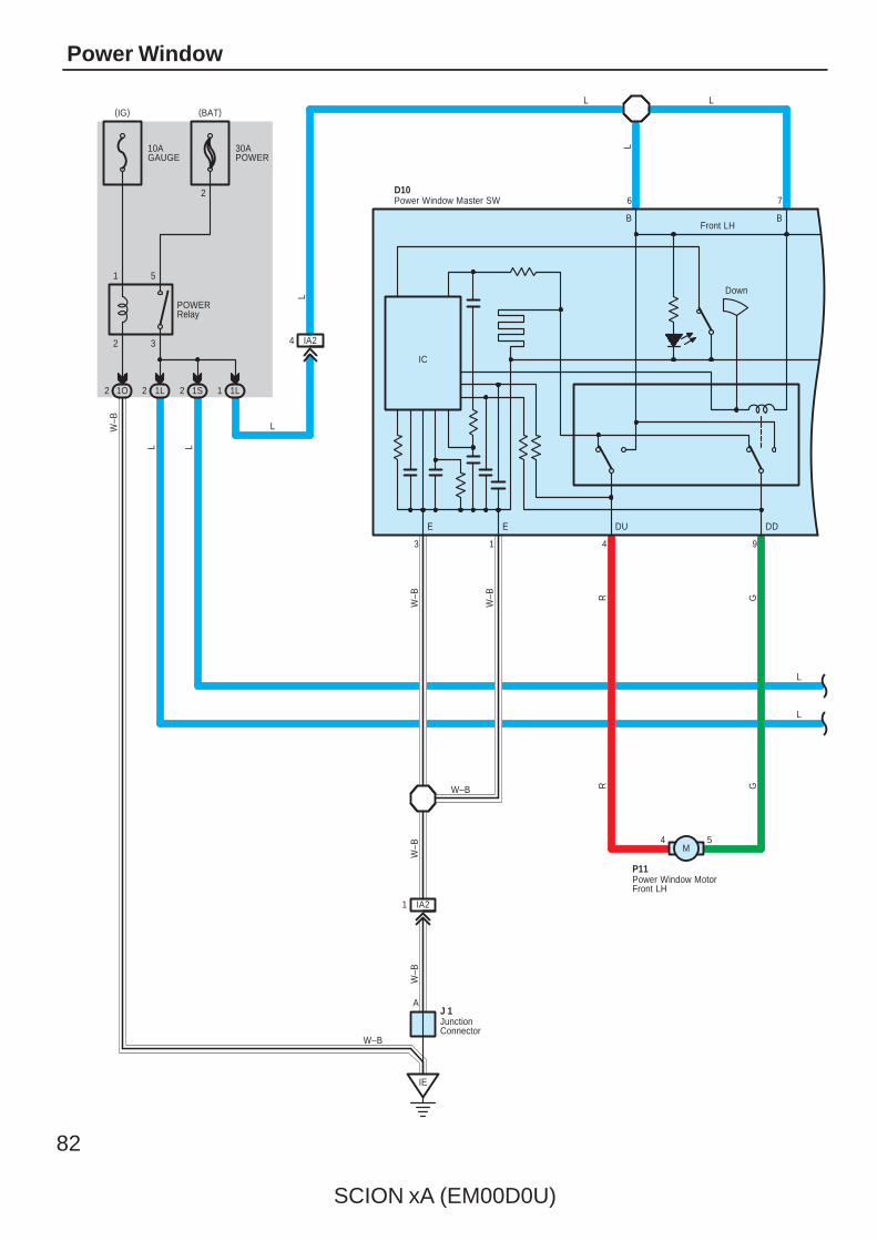
82
SCION xA (EM00D0U)
Power Window
E E DDDU
Down
Front LH
10AGAUGE
30APOWER
2 3
1 5
1O2 1L2 1S2 1L1
IA24
4
B
13 9
6
IC
W–B
4 5
IA21
P11
R G
POWERRelay
W–B
L L
LW
–B
W–B
W–B
W–B R G
L L
L
L
7
L
L
2
B
IE
AJ 1
W–B
D10
M
JunctionConnector
Power Window Master SW
Power Window MotorFront LH
(BAT)(IG)

SCION xA (EM00D0U)
83
Dow
n
Up
5 2
3 1
4 5
R G
P12
SU SD
U D
P 8
PU PD RLU RLD RRU RRD
Normal
Front RH Rear LH Rear RH
IH212 IH211
Dow
n
Up
5 2
3 1
5 4
R G
P14
SU SD
U D
P10
B44 B
1 BA1
P 9
DU
SDSU
P13
GR
45
13
25
Up
Dow
n
3 BA1
10 1613
L
L
12 IA2 IA211 IA22 IA23 IA29 IA210
IH29
IB28 IB23
B4
IB211 IB29
L–W
L–Y
R–Y
G–Y
R–B
G–B
R–B
R–B
R–B
G–B
G–B
G–B
R–Y
G–Y
R–Y
G–Y
R–Y
G–Y
LLL
L–W
L–Y
L
L
L–W
L–Y
121518
BA12 BB11 BB13 BB12
D10
M
Pow
er W
indo
w C
ontro
l SW
Fron
t RH
Pow
er W
indo
w C
ontro
l SW
Rea
r LH
Pow
er W
indo
w C
ontro
l SW
Rea
r R
H
Power Window Master SW
Power Window MotorFront RH
Power Window MotorRear LH
Power Window MotorRear RH
M M
Window Lock SW
Lock

84
SCION xA (EM00D0U)
Power Window
When the ignition SW is turned on, the current flows from the GAUGE fuse through the POWER relay to GROUND, thus thePOWER relay is turned on and the current flows through the POWER fuse to TERMINAL 5 of the POWER relay toTERMINAL 3 to TERMINAL B of the power window master SW and TERMINAL B of the power window control SW front RH,Rear LH and RH.
1. Manual Operation (Power Window Master SW)When the power window master SW (Driver’s) is pushed down one step, the current flows from TERMINAL B of the powerwindow master SW to TERMINAL DD to TERMINAL 5 of the power window motor front LH to TERMINAL 4 to TERMINALDU of the power window master SW to TERMINAL E to GROUND, and the motor rotates to open the window. When thepower window master SW is pulled up one step, the current flows from TERMINAL B of the power window master SW toTERMINAL DU to TERMINAL 4 of the power window motor front LH to TERMINAL 5 to TERMINAL DD of the power windowmaster SW to TERMINAL E to GROUND, and the motor rotates in the opposite direction from open and closes the window.All the other windows are opened/closed by operating the respective power window master SW. When the window lock SWis pushed to the lock side, the ground circuit to the passenger’s window becomes open. As a result, even if Open/Closeoperation of the passenger’s window is attempted, the current from TERMINAL E of the power window master SW is notgrounded and the motor does not rotate, so the passenger’s window can not be operated and window lock occurs.
2. Auto Down Operation (Driver’s Window)When the power window master SW (Driver’s) is pushed down two steps, the power window master SW determines that it isAUTO operation and the current flows from TERMINAL B of the power window master SW to TERMINAL DD to TERMINAL5 of the power window motor front LH to TERMINAL 4 to TERMINAL DU of the power window master SW to TERMINAL E toGROUND. Because the hold circuit inside the power window master SW keeps the relay on the down side activated, thepower window motor continues operating even if the power window master SW is released. When the driver’s window is fullyopened, the hold circuit turns off and the relay on the down side turns off, and auto down operation is completed.
3. Stopping of Auto Down Operation (Driver’s Window)When the power window master SW (Driver’s) is pulled to the up side during auto down operation, a ground circuit opens inthe power window master SW and current does not flow from TERMINAL DU of the power window master SW to TERMINALE, so the motor stops, causing auto down operation to stop. If the power window master SW is pulled continuously, the motorrotates in the up direction in manual up operation.
4. Manual Operation (Power Window Control SW Front RH, Rear LH and RH)With the power window control SW (Front RH, rear LH or RH) pulled to the up side, current flows from TERMINAL B of thepower window control SW to TERMINAL U to power window motor to TERMINAL D of the power window control SW toTERMINAL SD to TERMINAL PD, RLD or RRD of the power window master SW to TERMINAL E to GROUND and rotatesthe power window motor (Front RH, rear LH or RH) in the up direction. Up operation continues only while the power windowcontrol SW is pulled to the up side. When the window descends, the current flowing to the motor flows in the oppositedirection, and the motor rotates in reverse. When the window lock SW is pushed to the lock side, the ground circuit to thepassenger’s window becomes open. As a result, even if Open/Close operation of the passenger’s window is attempted, thecurrent from TERMINAL E of the power window master SW is not grounded and the motor does not rotate, so thepassenger’s window can not be operated and window lock occurs.
: Parts Location
Code See Page Code See Page Code See Page
D10 32 P9 33 P12 33
J1 31 P10 33 P13 33
P8 33 P11 33 P14 33
: Junction Block and Wire Harness Connector
Code See Page Junction Block and Wire Harness (Connector Location)
1L25 Instrument Panel Wire and Instrument Panel J/B (Lower Finish Panel)
1O25 Instrument Panel Wire and Instrument Panel J/B (Lower Finish Panel)
1S 24 Floor Wire and Instrument Panel J/B (Lower Finish Panel)
System Outline
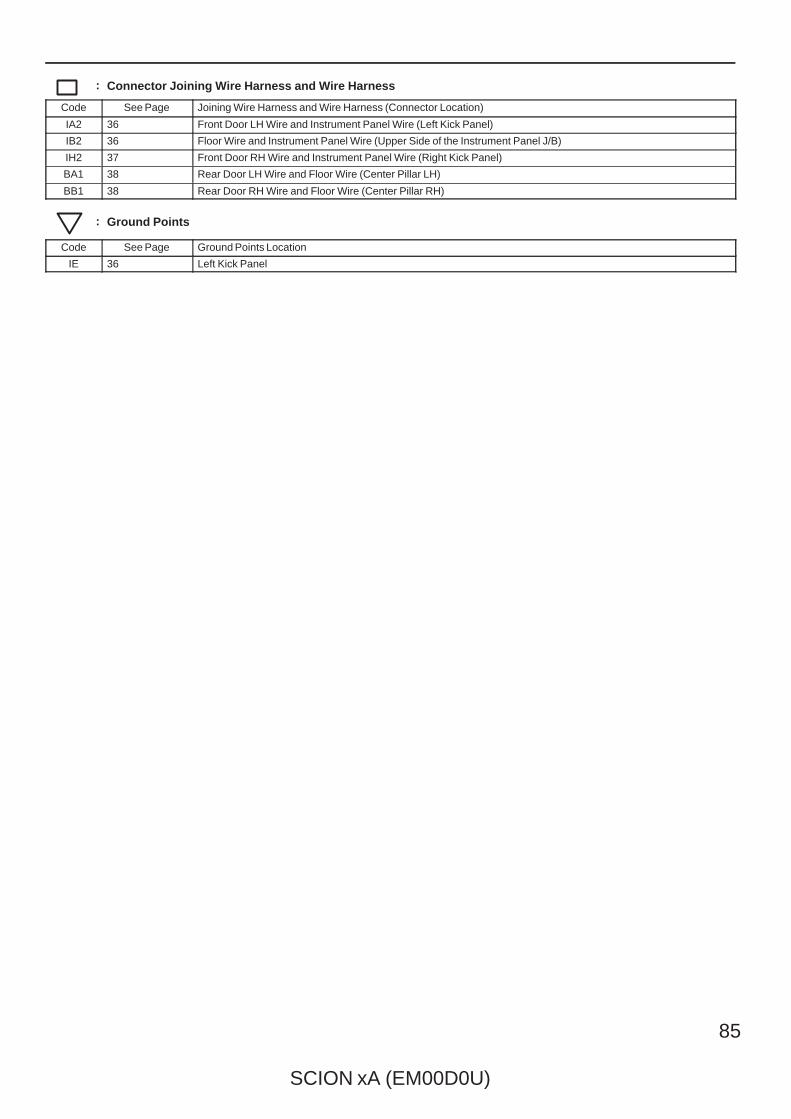
SCION xA (EM00D0U)
85
: Connector Joining Wire Harness and Wire Harness
Code See Page Joining Wire Harness and Wire Harness (Connector Location)
IA2 36 Front Door LH Wire and Instrument Panel Wire (Left Kick Panel)
IB2 36 Floor Wire and Instrument Panel Wire (Upper Side of the Instrument Panel J/B)
IH2 37 Front Door RH Wire and Instrument Panel Wire (Right Kick Panel)
BA1 38 Rear Door LH Wire and Floor Wire (Center Pillar LH)
BB1 38 Rear Door RH Wire and Floor Wire (Center Pillar RH)
: Ground Points
Code See Page Ground Points Location
IE 36 Left Kick Panel
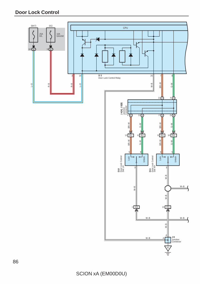
86
SCION xA (EM00D0U)
Door Lock Control
12 IA1
10 1L
25AD/L
10AGAUGE
1L3
W–B
W–B
G–W
BR
–W
W–B
G–W
BR
–W
6 IA1
A
IG
1 IA2 14 IH1
BR
–W
G–W
Lock
Unl
ock
D11
W–B
3
6 5
BR
–W
G–W
Lock
Unl
ock
D10
3
5 8
F B D B F B
F AD A
D B
10 IH1
R–B
R–B
9 IH1
25
BR
–W
G–W
3 14 7 8
L–O
L–O
W–B
W–B
W–B
W–B
W–B
A J 8
Doo
r Lo
ck C
ontro
lS
W R
H
JunctionConnector
Doo
r Lo
ck C
ontro
lS
W L
H
CPU
Junc
tion
Con
nect
or
J 4(
A), J
5( B
)
D 3Door Lock Control Relay
(IG)(BAT)
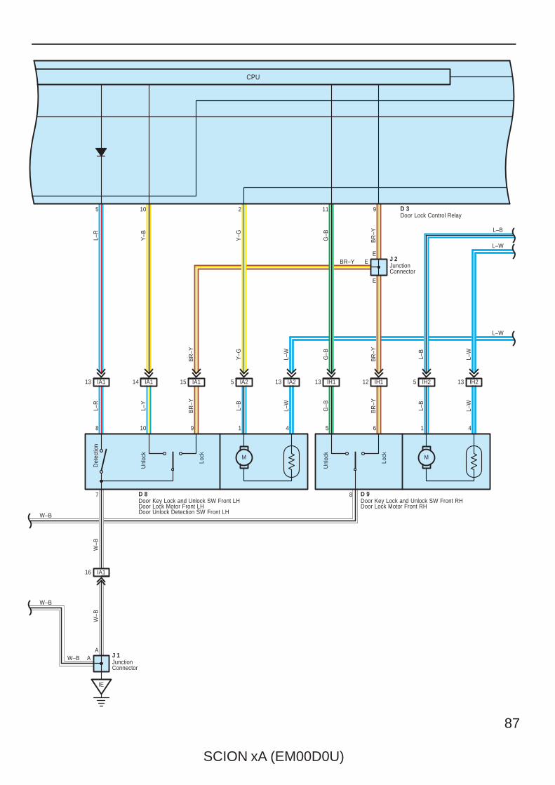
SCION xA (EM00D0U)
87
9108
W–B
W–B
A
13 IA1 14 IA1 15 IA1 13 IA25 IA2
D 8
41
M
16 IA1
IE
105
7
A
W–B
W–B
W–B
D 3
L–W
BR–Y
Unl
ock
Lock
2
L–R
Y–B
Y–G
L–R
L–Y
BR
–Y
L–B
L–W
BR
–Y
Y–G
L–W
J 1
Det
ectio
n
13 IH1 12 IH1
L–W
IH2
L–B
BR
–Y
G–B
Lock
Unl
ock
8
M
1 4
5
5 6
IH213
L–B
BR
–Y
L–B
G–B
G–B
L–W
L–W
D 9
J 2
BR
–Y
911
EE
E
Door Lock Control Relay
Door Key Lock and Unlock SW Front RHDoor Lock Motor Front RH
Door Key Lock and Unlock SW Front LHDoor Lock Motor Front LHDoor Unlock Detection SW Front LH
JunctionConnector
JunctionConnector
CPU
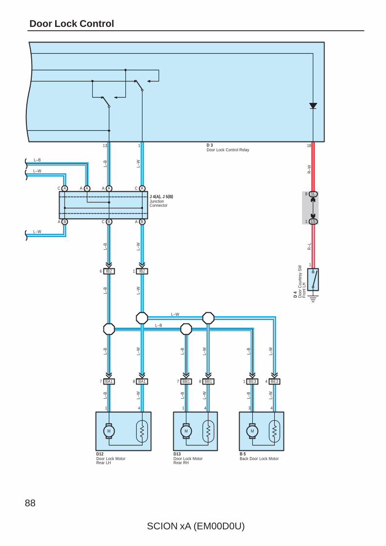
88
SCION xA (EM00D0U)
Door Lock Control
R–W
B 5
L–W
L–B
L–B
J 4(A), J 5(B)
D 4
1
13 1 18
8 1L
1 1S
L–B
L–W
3
L–W
D13D12
8 BB17 BB1
M
411
R–L
8 BA1BA17
L–W
A A A A
C B
L–B
L–W
L–B
6 IB2 1 IB2
BA BA
AC AC
L–W
L–B
L–W
L–B
4
L–W
L–W
L–B
M
L–B
D 3
4
L–W
L–B
M
L–W
L–W
L–B
Back Door Lock Motor
Door Lock Control Relay
Doo
r C
ourte
sy S
WFr
ont L
H
Door Lock MotorRear LH
Door Lock MotorRear RH
JunctionConnector
BE31 BE34
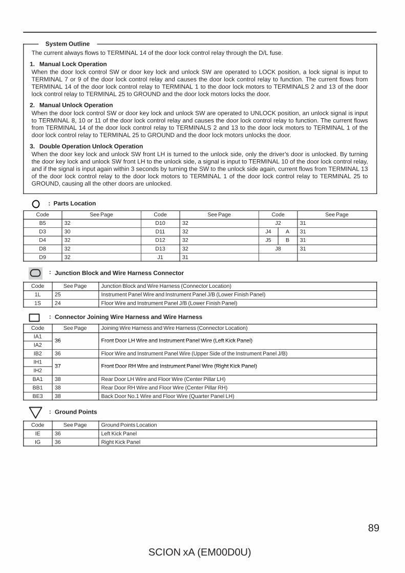
SCION xA (EM00D0U)
89
The current always flows to TERMINAL 14 of the door lock control relay through the D/L fuse.
1. Manual Lock OperationWhen the door lock control SW or door key lock and unlock SW are operated to LOCK position, a lock signal is input toTERMINAL 7 or 9 of the door lock control relay and causes the door lock control relay to function. The current flows fromTERMINAL 14 of the door lock control relay to TERMINAL 1 to the door lock motors to TERMINALS 2 and 13 of the doorlock control relay to TERMINAL 25 to GROUND and the door lock motors locks the door.
2. Manual Unlock OperationWhen the door lock control SW or door key lock and unlock SW are operated to UNLOCK position, an unlock signal is inputto TERMINAL 8, 10 or 11 of the door lock control relay and causes the door lock control relay to function. The current flowsfrom TERMINAL 14 of the door lock control relay to TERMINALS 2 and 13 to the door lock motors to TERMINAL 1 of thedoor lock control relay to TERMINAL 25 to GROUND and the door lock motors unlocks the door.
3. Double Operation Unlock OperationWhen the door key lock and unlock SW front LH is turned to the unlock side, only the driver’s door is unlocked. By turningthe door key lock and unlock SW front LH to the unlock side, a signal is input to TERMINAL 10 of the door lock control relay,and if the signal is input again within 3 seconds by turning the SW to the unlock side again, current flows from TERMINAL 13of the door lock control relay to the door lock motors to TERMINAL 1 of the door lock control relay to TERMINAL 25 toGROUND, causing all the other doors are unlocked.
: Parts Location
Code See Page Code See Page Code See Page
B5 32 D10 32 J2 31
D3 30 D11 32 J4 A 31
D4 32 D12 32 J5 B 31
D8 32 D13 32 J8 31
D9 32 J1 31
: Junction Block and Wire Harness Connector
Code See Page Junction Block and Wire Harness (Connector Location)
1L 25 Instrument Panel Wire and Instrument Panel J/B (Lower Finish Panel)
1S 24 Floor Wire and Instrument Panel J/B (Lower Finish Panel)
: Connector Joining Wire Harness and Wire Harness
Code See Page Joining Wire Harness and Wire Harness (Connector Location)
IA136 Front Door LH Wire and Instrument Panel Wire (Left Kick Panel)
IA236 Front Door LH Wire and Instrument Panel Wire (Left Kick Panel)
IB2 36 Floor Wire and Instrument Panel Wire (Upper Side of the Instrument Panel J/B)
IH137 Front Door RH Wire and Instrument Panel Wire (Right Kick Panel)
IH237 Front Door RH Wire and Instrument Panel Wire (Right Kick Panel)
BA1 38 Rear Door LH Wire and Floor Wire (Center Pillar LH)
BB1 38 Rear Door RH Wire and Floor Wire (Center Pillar RH)
BE3 38 Back Door No.1 Wire and Floor Wire (Quarter Panel LH)
: Ground Points
Code See Page Ground Points Location
IE 36 Left Kick Panel
IG 36 Right Kick Panel
System Outline

90
SCION xA (EM00D0U)
ECT and A/T Indicator
15AEFI
2
60A
MA
IN
15AAM2
2
1
2
2
B–R
1O1
1A7 6 1E
7 1O
1 3
2 5
2 2
2
W–R
2
W–R
D1
+B
1A11
1H8
ED
D3 C17
1P3
1H14
IE
7. 5AOBD
1P4
ID313
1P17
1O2
1P13
IF2
CG
2
4
ODMS
6 C
7 1P
5 4
1 1E
16
B–O
BAT
TC
13
D 1
P–B
15
P–B
B–Y
B–Y
EFIRelay
Battery
B
B
W–B
W–B
W–B
W–B
E 3(A), E 4(B), E 5(C), E 6(D)
5 6
I10
W–B
BATT TC
AM2 IG2
ST2
2
F10(
A), (
B)
B–R
SG
B–R
BR
O 2B
R
W–B
G–B
BR
BR
1H7
B–R
Data LinkConnector 3
Engine Control Module
Fusi
ble
Link
Blo
ck
Ignition SW
O/D
Mai
n S
W
D30
NSW
D12
STA
8 1G
IF213
P
N
B–YB
B–Y
BB
BB
4
Par
k/N
eutra
lP
ositi
on S
W
P 1
5
4
B
(BAT)(BAT)
D2
+B2
B–R
IF111 IF14(w/o VSC)B2(w/ VSC)A3
B–Y
D8
MREL
D9
IGSW
ID22
6 1O
B–R
GR
GR
GR
B–R
B–R

SCION xA (EM00D0U)
91
10ASTOP
1B8
B24B11B13B12B19B8B9
5 10 2 3 8 4 1
S1 S2 ST SLT+ SLSLT– THO1
W–G
W–R
B–R
W–L W G Y–G
1
2
C4 B35
12
B27
A28
W–BBR
W–BBR
BR
ECE02E03
22 D
EC
6 A4 B
E 1
G–B
G–W
No.
2
S 6
T 2
G–W
R B
E 3(A), E 4(B), E 5(C), E 6(D)
STP NT+ NT–
E2
BR
S2S1 ST SLT+ THOSLT–
B Y G LG OGR
O
6
E2
BR
E1
3 A7 A
E01
BR
A
No.
1
SL
BR
BR
OC1–OC1+
R–B
W
R–Y
C 2
12 A
2 1
13
B–RB–R
Camshaft TimingOil Control Valve
Electronically ControlledTransmission Solenoid
Engine Control Module
StopLightSW
Turbine SpeedSensor
(BAT)
IG
JunctionConnector
J 8A
BR
BR
1B2
1H2
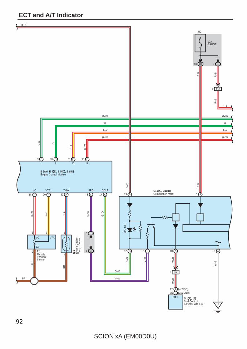
92
SCION xA (EM00D0U)
ECT and A/T Indicator
2
1 3
A18 A20 A32
VC VTA1 THW
R–W Y–R R–L
E 2
BR
BR
BR
T 1
C8
SPD
C14
ODLP
1H3
1F6
V–W
G–O
VTAVC
E2
C9 C10 C21 C11
R–Y
G
L 2 D R
G–W
Eng
ine
Coo
lant
Tem
p.
Sen
sor
ThrottlePositionSensor
V–W
21 B
C10(A), C11(B)
R–B
R–B
R–B
13 1G
9 IF2
10AGAUGE
1E5
O/D
OFF
W–B
G–W
G
R–Y
R–W
B–R
R–B
B–R
G–W
G
R–Y
R–W
G–O
IF
A1B13
12 B A310 A
ID23
SP1
W–R
W–R
V–W
G–O
Combination Meter
(IG)
(w/o VSC)B26(w/ VSC)A12
2
1
R–W
R–B
Skid ControlActuator with ECU
S 1(A), (B)
E 3(A), E 4(B), E 5(C), E 6(D)Engine Control Module
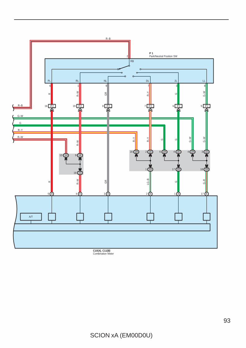
SCION xA (EM00D0U)
93
R–W
R–Y
G
G–W
P 1
B
6
17
1H
C10(A), C11(B)
4 1H
A/T
RB
R–B
G–WGR–YGR
R–WR
R–W
R–Y
R–Y G G
G–W
G–W
G–RG
LG–B
GRR
R–W
1H13
LL2LDLNLRLPL
2
837916
IF216 IF219 IF28 IF27 IF26 IF25
3 1E
1G1816 1G
1E94 1E
1G17
16 1H 2 1E
1G1
B1B2B3B4B5
Combination Meter
Park/Neutral Position SW
R–B
94
SCION xA (EM00D0U)
ECT and A/T Indicator
Previous automatic transaxle have selected each gear shift using the mechanically controlled throttle hydraulic pressure,governor hydraulic pressure and lock–up hydraulic pressure. The electronically controlled transmission, however, electricallycontrols the line pressure and lock–up pressure etc., through the solenoid valve. Engine control module controls eachsolenoid valve based on the input signals from each sensor, which makes smooth driving possible by shift selection for eachgear that is most appropriate to the driving conditions at that time.
1. Gear Shift OperationDuring driving, the engine control module selects the shift for each gear which is most appropriate to the driving conditions,based on input signals from the engine coolant temp. sensor to TERMINAL THW of the engine control module, and also theinput signals to TERMINAL NT+ of the engine control module from the turbine speed sensor devoted to the direct clutch.Current is then output to the electronically controlled transmission solenoid. When shifting to 1st gear, current flows fromTERMINAL S1 of the engine control module to TERMINAL 5 of the electronically controlled transmission solenoid toGROUND, and from TERMINAL S2 of the engine control module to TERMINAL 10 of the electronically controlledtransmission solenoid to GROUND, and continuity to solenoids No.1 and No.2 causes the shift.For the 2nd gear, current flows from TERMINAL S1 of the engine control module to TERMINAL 5 of the electronicallycontrolled transmission solenoid to GROUND, and continuity to the solenoid No.1 causes the shift.For the 3rd gear, there is no continuity to either No.1 or No.2 solenoid.Shifting into 4th gear (Overdrive) takes place when current flows from TERMINAL S2 of the engine control module toTERMINAL 10 of the electronically controlled transmission solenoid to GROUND, and continuity to the solenoid No.2 causesthe shift.
2. Lock–Up OperationWhen the engine control module judges from each signal that lock–up operation conditions have been met, current flowsfrom TERMINAL SL of the engine control module to TERMINAL 4 of the electronically controlled transmission solenoid toGROUND, causing continuity to the lock–up solenoid and causing lock–up operation.
3. Clutch Pressure ControlThe electronically controlled transmission solenoid is controlled by the current from TERMINAL SL of the engine controlmodule, and controls the accumulator hydraulic pressure.As a result, the clutch to hydraulic pressure is adjusted precisely, and allows stable shift change.
4. Line Pressure ControlThe electronically controlled transmission solenoid is controlled by the current from TERMINAL SLT+ of the engine controlmodule, and controls the throttle hydraulic pressure.As a result, the line pressure can be controlled precisely, and the to hydraulic pressure is adjusted according to the shiftchange condition, and allows smooth shift change.
5. Shifting Control in Uphill/Downhill TravelingThis system determines whether the vehicle is traveling on an incline or decline from the throttle opening angle, vehicleacceleration condition and brake pedal operation, and controls the shift up to O/D to allow smooth driving.
6. Clutch to Clutch ControlWhen shifting from the 3rd gear to the 4th gear, the current from the engine control module TERMINAL ST controls theelectronically controlled transmission solenoid, to control the drain orifice hydraulic pressure (Switch orifice). Theelectronically controlled transmission solenoid is also controlled by the current from the engine control module TERMINALSLT+, to adjust the hydraulic pressure precisely, which ensures smooth shifting.
7. Stop Light SW CircuitIf the brake pedal is depressed (Stop light SW on) when driving in lock–up condition, a signal is input to TERMINAL STP ofthe engine control module, the engine control module operates and continuity to the lock–up solenoid is cut.
8. Overdrive Circuit∗ Overdrive on
When the engine is turned on from ignition off, the engine control module turns the O/D on. When the O/D main SW ispushed while the O/D is off, a signal is input into TERMINAL ODMS of the engine control module, and the O/D is turnedon by the engine control module. In this case, the engine control module controls the gear shift according to the vehicle’sdriving condition, using the O/D range. At this time, the O/D off indicator light is off.
∗ Overdrive offWhen the O/D main SW is pushed while the O/D is on, a signal is input into TERMINAL ODMS of the engine controlmodule, and the O/D is turned off. At this time, the current flows through the O/D off indicator light to TERMINAL ODLP ofthe engine control module. As a result, the O/D off indicator light turns on, and the engine control module controls the gearshift according to the vehicle’s driving condition, without using the O/D range.
System Outline
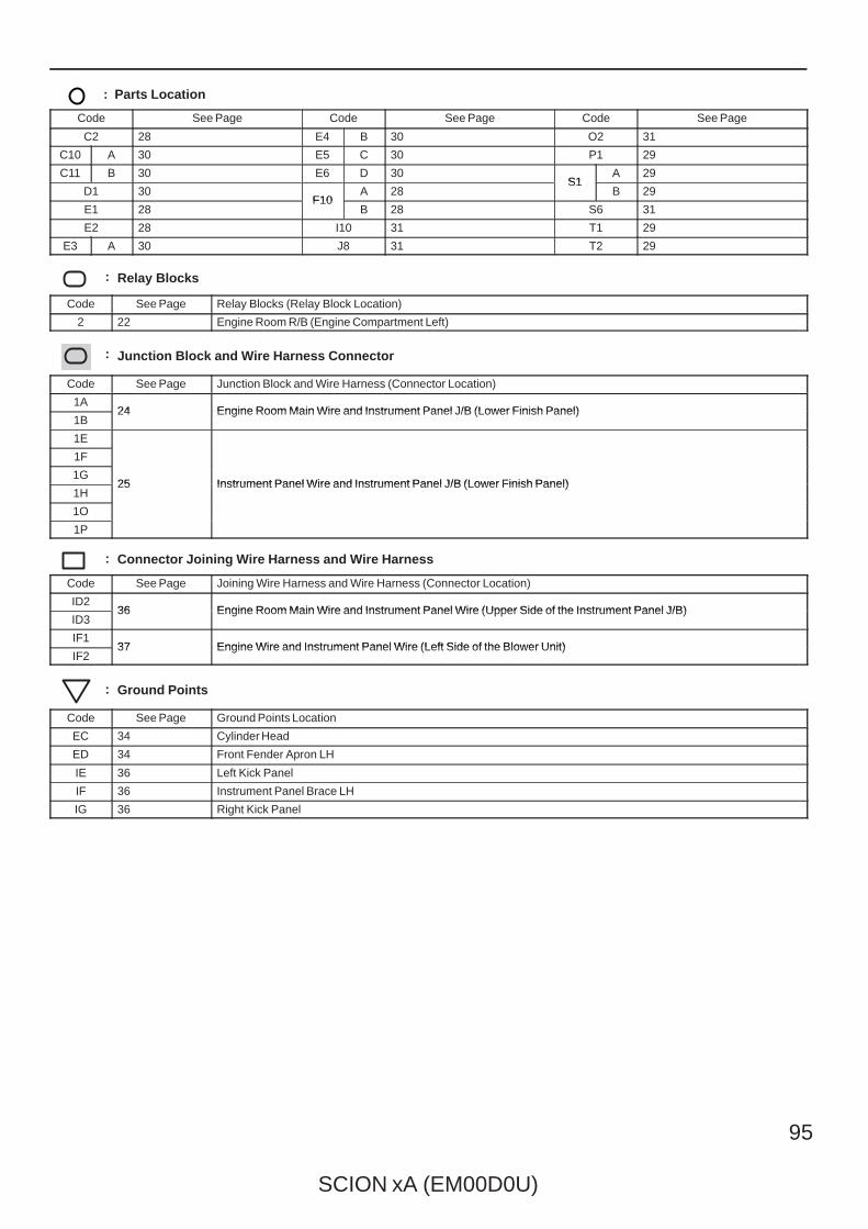
SCION xA (EM00D0U)
95
: Parts Location
Code See Page Code See Page Code See Page
C2 28 E4 B 30 O2 31
C10 A 30 E5 C 30 P1 29
C11 B 30 E6 D 30S1
A 29
D1 30F10
A 28S1
B 29
E1 28F10
B 28 S6 31
E2 28 I10 31 T1 29
E3 A 30 J8 31 T2 29
: Relay Blocks
Code See Page Relay Blocks (Relay Block Location)
2 22 Engine Room R/B (Engine Compartment Left)
: Junction Block and Wire Harness Connector
Code See Page Junction Block and Wire Harness (Connector Location)
1A24 Engine Room Main Wire and Instrument Panel J/B (Lower Finish Panel)
1B24 Engine Room Main Wire and Instrument Panel J/B (Lower Finish Panel)
1E
25 Instrument Panel Wire and Instrument Panel J/B (Lower Finish Panel)
1F
25 Instrument Panel Wire and Instrument Panel J/B (Lower Finish Panel)1G
25 Instrument Panel Wire and Instrument Panel J/B (Lower Finish Panel)1H
25 Instrument Panel Wire and Instrument Panel J/B (Lower Finish Panel)
1O
1P
: Connector Joining Wire Harness and Wire Harness
Code See Page Joining Wire Harness and Wire Harness (Connector Location)
ID236 Engine Room Main Wire and Instrument Panel Wire (Upper Side of the Instrument Panel J/B)
ID336 Engine Room Main Wire and Instrument Panel Wire (Upper Side of the Instrument Panel J/B)
IF137 Engine Wire and Instrument Panel Wire (Left Side of the Blower Unit)
IF237 Engine Wire and Instrument Panel Wire (Left Side of the Blower Unit)
: Ground Points
Code See Page Ground Points Location
EC 34 Cylinder Head
ED 34 Front Fender Apron LH
IE 36 Left Kick Panel
IF 36 Instrument Panel Brace LH
IG 36 Right Kick Panel
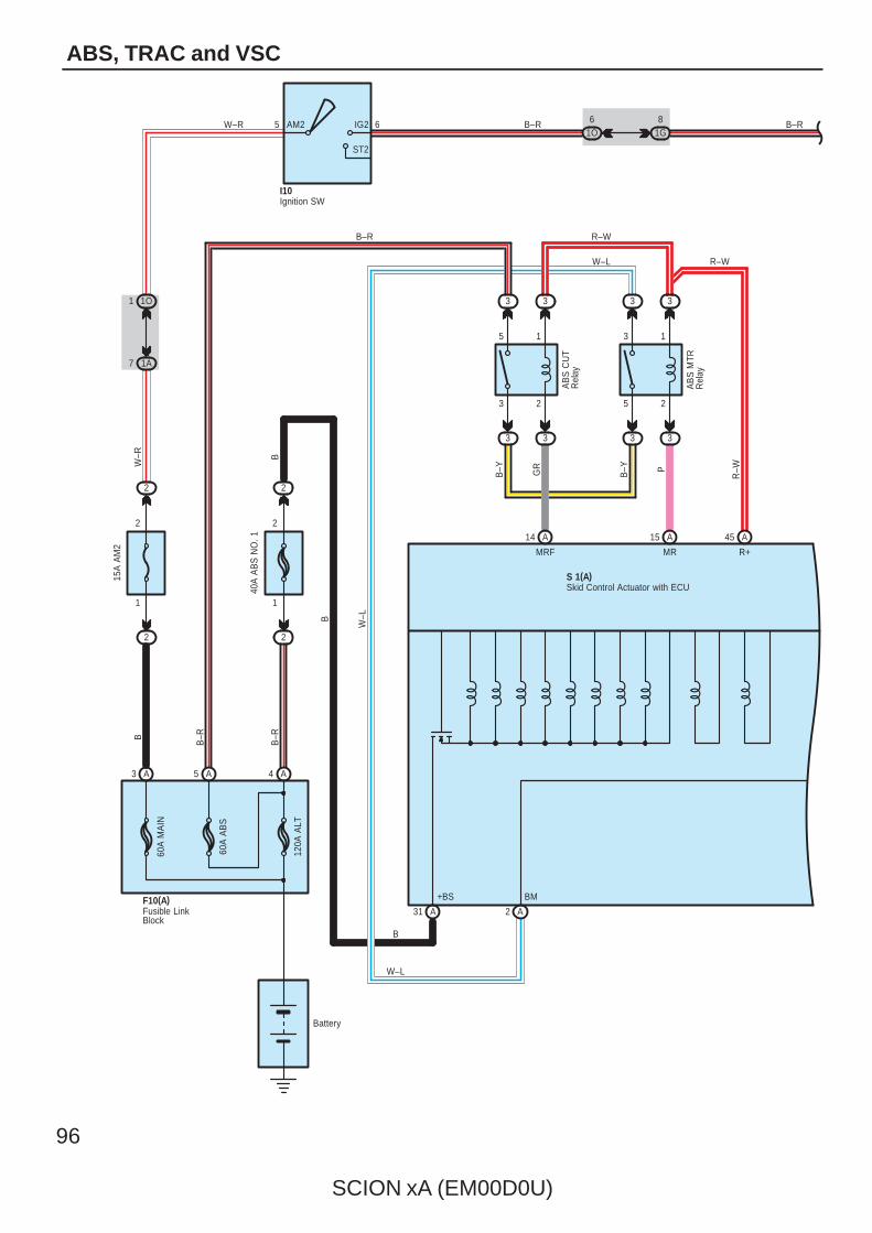
96
SCION xA (EM00D0U)
ABS, TRAC and VSC
B
MRF R+
I10
S 1(A)
5
2
6
3
2
AM2
60A
MA
IN
120A
ALT
60A
AB
S
Battery
2
1
3
5 1
2
3
5
B–R
AB
S C
UT
Rel
ay
AB
S M
TRR
elay
R–W
PB–Y GR
B–R
B–Y
+BS BM
MR
2
1
40A
AB
S N
O. 1
2
1
15A
AM
2B–RW–R
B
W–R
B–RIG2
ST2
F10(A)
1G8
1O6
3 331O1
2
2
1A7
3 3 3 3
Skid Control Actuator with ECU
Fusible LinkBlock
Ignition SW
R–W
R–WW–L
W–L
B
B
W–L
A5A3 A4
B–R
A15A14 A45
A31 2 A
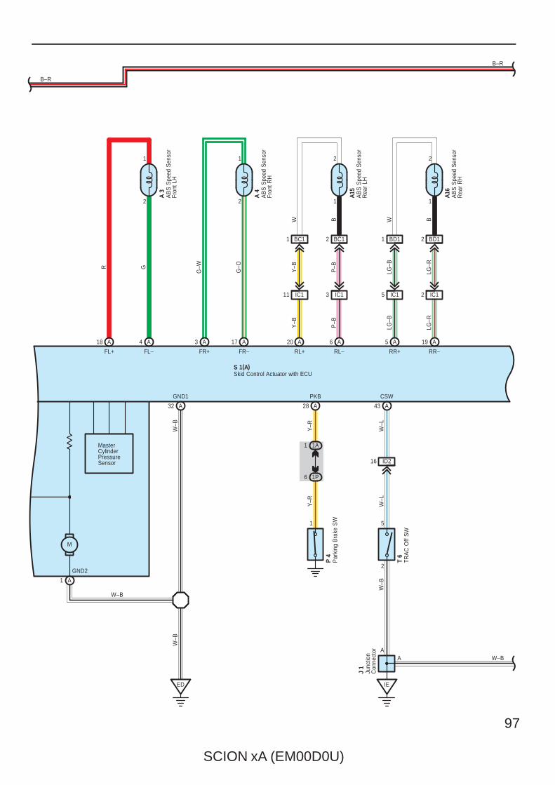
SCION xA (EM00D0U)
97
ED
BC1 BD1 BD11 BC1
1A
B–R
W–B
GND1
W–B
W–B
FL–FL+ FR+ FR– RL+ RL– RR+ RR–
2
1
2
1
1
2
1
2
Y–B
P–B
LG–B
LG–R
Y–B
P–B
R G
G–W
G–O
LG–B
LG–R
B–R
212
W B W B
2
5
W–L
W–B
CSW
AA
W–L
W–B
16 ID2
A 3
A 4
A15
A16
S 1(A)
IC111 IC12IC15IC13
T 6
J 1
IE
1
Y–R
PKB
Y–R
P 4
1
1P6
Skid Control Actuator with ECU
AB
S S
peed
Sen
sor
Fron
t LH
AB
S S
peed
Sen
sor
Fron
t RH
AB
S S
peed
Sen
sor
Rea
r LH
AB
S S
peed
Sen
sor
Rea
r R
H
Junc
tion
Con
nect
or
Par
king
Bra
ke S
W
TRA
C O
ff S
W
M
MasterCylinderPressureSensor
GND2
A18 A4 A3 A17 A20 A6 A5 A19
A1
A32 A28 A43
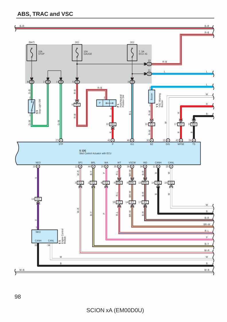
98
SCION xA (EM00D0U)
ABS, TRAC and VSC
13
V
NEO
V
7
ID2
NEO
3
7. 5AECU–IG
1B
17 ID210 EB1
W–B
B–R
10ASTOP
1B 5 1E
10AGAUGE
IF29
R–B
R–B
12 1B
G–W
S 6
1
2
8 1B
9 EB1
BZ
R–W
S 1(A)
10 ID2
R
W
D/G WFSE
R
STP
G–W
G–B
P1
2
Buz
zer
R–W
B–Y
BRL
P
WA
R–L
WT
BR
–W
VSCW
R–L
BR
–W
B–R
B
CANH
B
IND
B–R
B–YW
–RW
–R
SP1
V 5
R
P
R
R–L
BR
–W
B–R
IG1
B–L
EB18 EB113 ID214ID261 ID23 ID2
IF218 14 IF2 IF217
W–B
W–R
B–Y
P
R–L
BR–W
B–R
B
W
R
W
L
B–R
1G13
1H11 L
R–B
R–B
L
Skid Control Actuator with ECU
Sto
p Li
ght S
W
VS
C W
arni
ngB
uzze
r
W
CANL
W
ID215
6
P
2
Par
k/N
eutra
lP
ositi
on S
W
P 1
R–B
(BAT) (IG) (IG)
Eng
ine
Con
trol
Mod
ule
E 5CANH CANL
33 34
W
B
W
B
TS
B
B
ID38
A27 A40 A46 A30 A13 A42 A24
A10 A12 A44 A29 A35 A36 A34 A11 A25
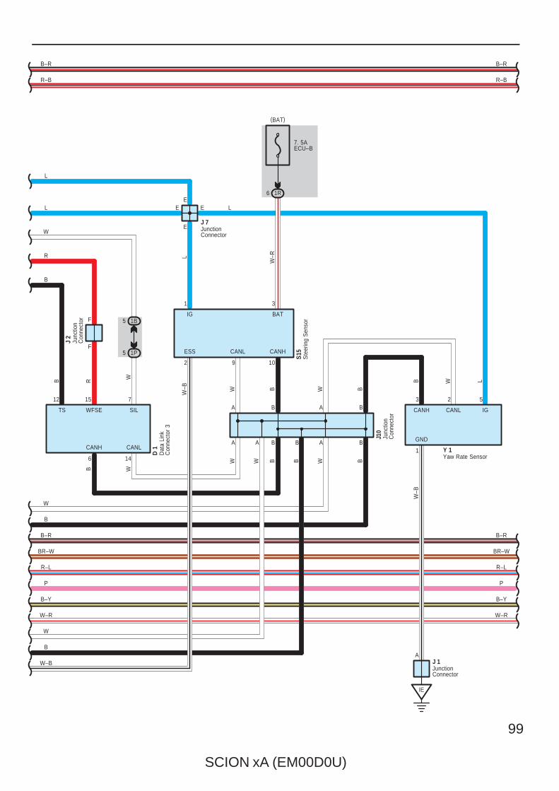
SCION xA (EM00D0U)
99
R
1R
7. 5AECU–B
6
5 1P
5
W
7
1B
SIL
D 1
F
F
Y 1CANH
WFSE
14
15
W–R
B–Y
B
B
A
A
W B W B
W BBW
LW
–B
B W L
B–R
W–B
A B
A B
1 3
2
3 2 5
1
9 10
GND
CANL CANH
IG BAT
ESS
CANH CANL IG
BR–W
R–L
P
W–R
B–R
E
E
CANL
6
S15
J10
L
W
R
W
B
B–R
BR–W
R–L
P
B–Y
W–R
E
W–B
B–R
E
J 7
L
L
R–B R–B
WB
Dat
a Li
nkC
onne
ctor
3
JunctionConnector
Junc
tion
Con
nect
or
Ste
erin
g S
enso
r
Yaw Rate Sensor
(BAT)
IE
JunctionConnector
J 1A
W
B
A B
Junc
tion
Con
nect
or
J 2
TS
12
B
B
BW
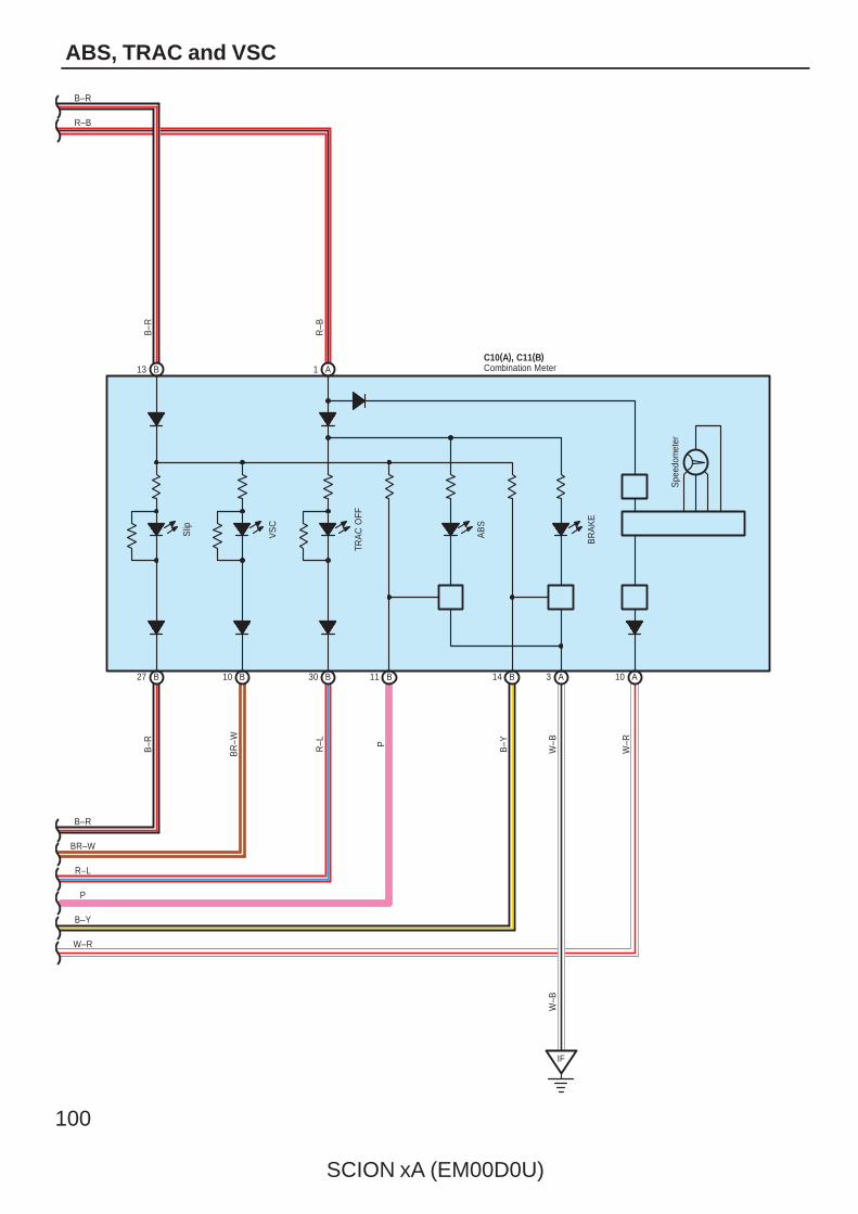
100
SCION xA (EM00D0U)
ABS, TRAC and VSC
1 A13 B
10 A3 A14 B11 B30 B10
IF
C10(A), C11(B)
27 B
W–R
P
R–L
BR–W
B–R
BR
–W
R–L P
B–R
W–B
W–B
TRA
C O
FF
VS
C
R–B
Slip
W–R
AB
S
B–Y
B–Y
B
B–R
B–R
BR
AK
E
Spe
edom
eter
R–B
Combination Meter
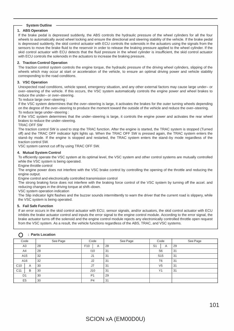
SCION xA (EM00D0U)
101
1. ABS OperationIf the brake pedal is depressed suddenly, the ABS controls the hydraulic pressure of the wheel cylinders for all the fourwheels to automatically avoid wheel locking and ensure the directional and steering stability of the vehicle. If the brake pedalis depressed suddenly, the skid control actuator with ECU controls the solenoids in the actuators using the signals from thesensors to move the brake fluid to the reservoir in order to release the braking pressure applied to the wheel cylinder. If theskid control actuator with ECU detects that the fluid pressure in the wheel cylinder is insufficient, the skid control actuatorwith ECU controls the solenoids in the actuators to increase the braking pressure.
2. Traction Control OperationThe traction control system controls the engine torque, the hydraulic pressure of the driving wheel cylinders, slipping of thewheels which may occur at start or acceleration of the vehicle, to ensure an optimal driving power and vehicle stabilitycorresponding to the road conditions.
3. VSC OperationUnexpected road conditions, vehicle speed, emergency situation, and any other external factors may cause large under– orover–steering of the vehicle. If this occurs, the VSC system automatically controls the engine power and wheel brakes toreduce the under– or over–steering.To reduce large over–steering :If the VSC system determines that the over–steering is large, it activates the brakes for the outer turning wheels dependingon the degree of the over–steering to produce the moment toward the outside of the vehicle and reduce the over–steering.To reduce large under–steering :If the VSC system determines that the under–steering is large, it controls the engine power and activates the rear wheelbrakes to reduce the under–steering.TRAC OFF SWThe traction control SW is used to stop the TRAC function. After the engine is started, the TRAC system is stopped (Turnedoff) and the TRAC OFF indicator light lights up. When the TRAC OFF SW is pressed again, the TRAC system enters thestand–by mode. If the engine is stopped and restarted, the TRAC system enters the stand–by mode regardless of thetraction control SW.VSC system cannot cut off by using TRAC OFF SW.
4. Mutual System ControlTo efficiently operate the VSC system at its optimal level, the VSC system and other control systems are mutually controlledwhile the VSC system is being operated.Engine throttle controlThe engine power does not interfere with the VSC brake control by controlling the opening of the throttle and reducing theengine output.Engine control and electronically controlled transmission controlThe strong braking force does not interfere with the braking force control of the VSC system by turning off the accel. andreducing changes in the driving torque at shift–down.VSC system operation indicationThe Slip indicator light flashes and the buzzer sounds intermittently to warn the driver that the current road is slippery, whilethe VSC system is being operated.
5. Fail Safe FunctionIf an error occurs in the skid control actuator with ECU, sensor signals, and/or actuators, the skid control actuator with ECUinhibits the brake actuator control and inputs the error signal to the engine control module. According to the error signal, thebrake actuator turns off the solenoid and the engine control module rejects any electronically controlled throttle open requestfrom the VSC system. As a result, the vehicle functions regardless of the ABS, TRAC, and VSC systems.
: Parts Location
Code See Page Code See Page Code See Page
A3 28 F10 A 28 S1 A 29
A4 28 I10 31 S6 31
A15 32 J1 31 S15 31
A16 32 J2 31 T6 31
C10 A 30 J7 31 V5 31
C11 B 30 J10 31 Y1 31
D1 30 P1 29
E5 30 P4 31
System Outline
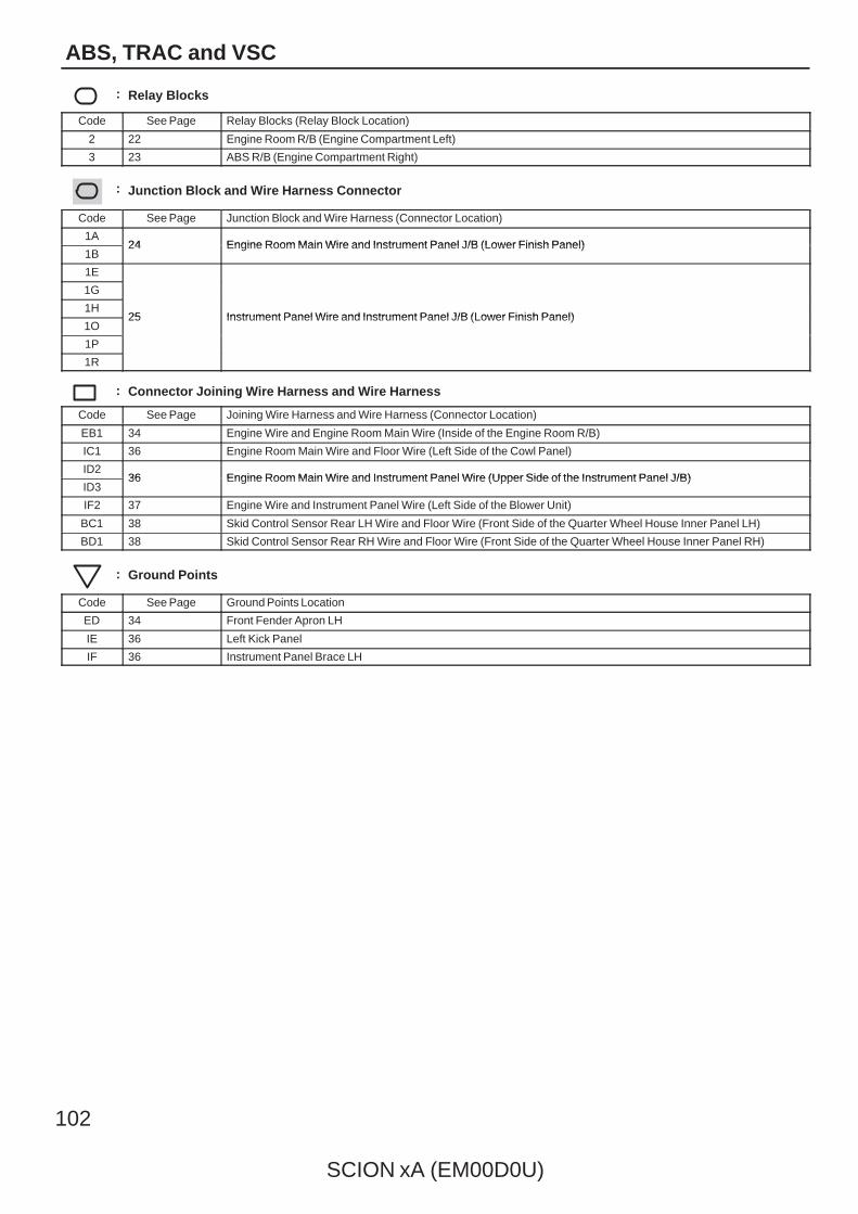
102
SCION xA (EM00D0U)
ABS, TRAC and VSC
: Relay Blocks
Code See Page Relay Blocks (Relay Block Location)
2 22 Engine Room R/B (Engine Compartment Left)
3 23 ABS R/B (Engine Compartment Right)
: Junction Block and Wire Harness Connector
Code See Page Junction Block and Wire Harness (Connector Location)
1A24 Engine Room Main Wire and Instrument Panel J/B (Lower Finish Panel)
1B24 Engine Room Main Wire and Instrument Panel J/B (Lower Finish Panel)
1E
25 Instrument Panel Wire and Instrument Panel J/B (Lower Finish Panel)
1G
25 Instrument Panel Wire and Instrument Panel J/B (Lower Finish Panel)1H
25 Instrument Panel Wire and Instrument Panel J/B (Lower Finish Panel)1O
25 Instrument Panel Wire and Instrument Panel J/B (Lower Finish Panel)
1P
1R
: Connector Joining Wire Harness and Wire Harness
Code See Page Joining Wire Harness and Wire Harness (Connector Location)
EB1 34 Engine Wire and Engine Room Main Wire (Inside of the Engine Room R/B)
IC1 36 Engine Room Main Wire and Floor Wire (Left Side of the Cowl Panel)
ID236 Engine Room Main Wire and Instrument Panel Wire (Upper Side of the Instrument Panel J/B)
ID336 Engine Room Main Wire and Instrument Panel Wire (Upper Side of the Instrument Panel J/B)
IF2 37 Engine Wire and Instrument Panel Wire (Left Side of the Blower Unit)
BC1 38 Skid Control Sensor Rear LH Wire and Floor Wire (Front Side of the Quarter Wheel House Inner Panel LH)
BD1 38 Skid Control Sensor Rear RH Wire and Floor Wire (Front Side of the Quarter Wheel House Inner Panel RH)
: Ground Points
Code See Page Ground Points Location
ED 34 Front Fender Apron LH
IE 36 Left Kick Panel
IF 36 Instrument Panel Brace LH

SCION xA (EM00D0U)
103
Memo
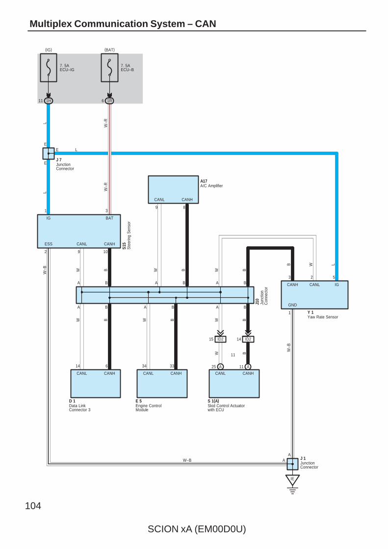
104
SCION xA (EM00D0U)
Multiplex Communication System – CAN
1R
7. 5AECU–B
6
Y 1
W–R
B
B
A
A
W B W B
W BBW
L W–R
W–B
B W L
W–B
A B
A B
1 3
2
3 2 5
1
9 10
GND
CANL CANH
IG BAT
ESS
CANH CANL IG
E
E
S15
J10
IE
E
J 7
L
JunctionConnector
Junc
tion
Con
nect
or
Ste
erin
g S
enso
r
Yaw Rate Sensor
1H
7. 5AECU–IG
11
L
ID215 ID214
W B
14 6
11
CANL CANH CANL CANH
D 1Data LinkConnector 3
S 1(A)Skid Control Actuatorwith ECU
W–B
(IG) (BAT)
JunctionConnector
J 1A
A
BA
BW
34 33
CANL CANH
E 5Engine ControlModule
CANL CANH
9 8
A B
BW
A/C AmplifierA17
A25 A11
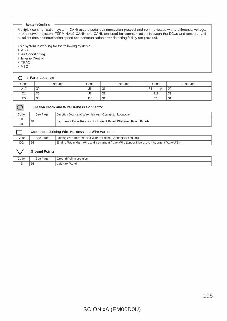
SCION xA (EM00D0U)
105
Multiplex communication system (CAN) uses a serial communication protocol and communicates with a differential voltage.In this network system, TERMINALS CANH and CANL are used for communication between the ECUs and sensors, andexcellent data communication speed and communication error detecting facility are provided.
This system is working for the following systems:∗ ABS∗ Air Conditioning∗ Engine Control∗ TRAC∗ VSC
: Parts Location
Code See Page Code See Page Code See Page
A17 30 J1 31 S1 A 29
D1 30 J7 31 S15 31
E5 30 J10 31 Y1 31
: Junction Block and Wire Harness Connector
Code See Page Junction Block and Wire Harness (Connector Location)
1H25 Instrument Panel Wire and Instrument Panel J/B (Lower Finish Panel)
1R25 Instrument Panel Wire and Instrument Panel J/B (Lower Finish Panel)
: Connector Joining Wire Harness and Wire Harness
Code See Page Joining Wire Harness and Wire Harness (Connector Location)
ID2 36 Engine Room Main Wire and Instrument Panel Wire (Upper Side of the Instrument Panel J/B)
: Ground Points
Code See Page Ground Points Location
IE 36 Left Kick Panel
System Outline
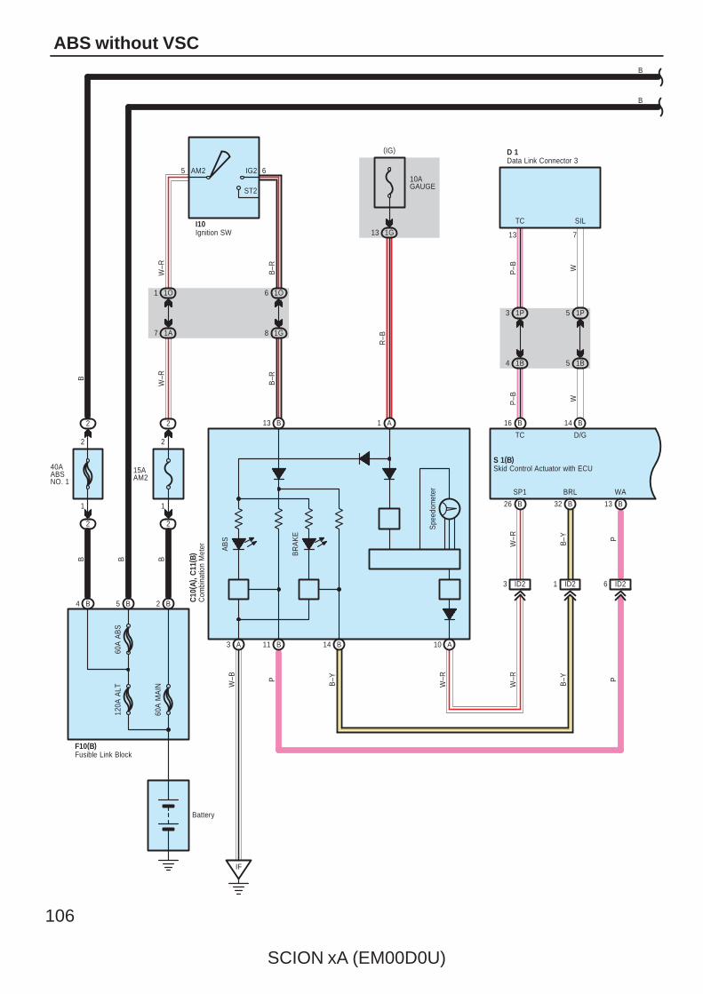
106
SCION xA (EM00D0U)
ABS without VSC
10AGAUGE
1G13
R–B
WA
1O
S 1(B)
D/GTC
713
4
WP–B
WP–B
1P5
1B5
3 1P
1B
TC SIL
D 1B
60A
MA
IN
15AAM2
2
2
2
1O1
1A7
5 6AM2 IG2
ST2
1
6
1G8
W–R
B–R
W–R
B–R
Battery
I10
120A
ALT
60A
AB
SBB
SP1 BRL
ID26ID21ID23
AB
S
BR
AK
E
Spe
edom
eter
A3 B11 B14 A10
B13 A1
IF
W–R
B–Y P
W–R
B–YP
W–B
W–R
B–Y P
B
B
Skid Control Actuator with ECU
Data Link Connector 3
Ignition SW
2
2
2
1
B
Fusible Link BlockF10(B)
Com
bina
tion
Met
erC
10( A
) , C
11( B
)
(IG)
B4 B5 B2
40AABSNO. 1
B16 B14
13 B32 B26 B
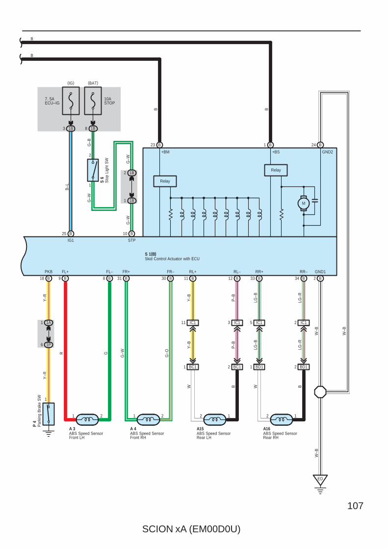
SCION xA (EM00D0U)
107
10ASTOP
1B8
G–B
3 1B
2 BC1
1
2
1 1B
2 1B
GND1
W–B
W–B
ED
21
R G
FL+ FL–
IG1
G–W
A 3
B–L
G–W
21
G–W
G–O
FR+ FR–
A 4
12
Y–B
P–B
RL+ RL–
A15
12
LG–B
LG–R
RR+ RR–
A16
IC111 IC13 IC15 IC12
Y–B
P–B
LG–B
LG–R
S 6
M
Relay
Relay
W–B
7. 5AECU–IG
BD11 BD12BC11
W B W B
+BM +BS
STP
S 1(B)
PKB
1A1
1P6
1
Y–R
Y–R
P 4
G–W
B
B
B B
Skid Control Actuator with ECU
ABS Speed SensorFront LH
ABS Speed SensorFront RH
ABS Speed SensorRear LH
ABS Speed SensorRear RH
Par
king
Bra
ke S
W
Sto
p Li
ght S
W
(IG) (BAT)
GND2
B2
B25 B10
B1 B24B23
B3433 B12 B11 B30 B31 B8 B9 B18 B
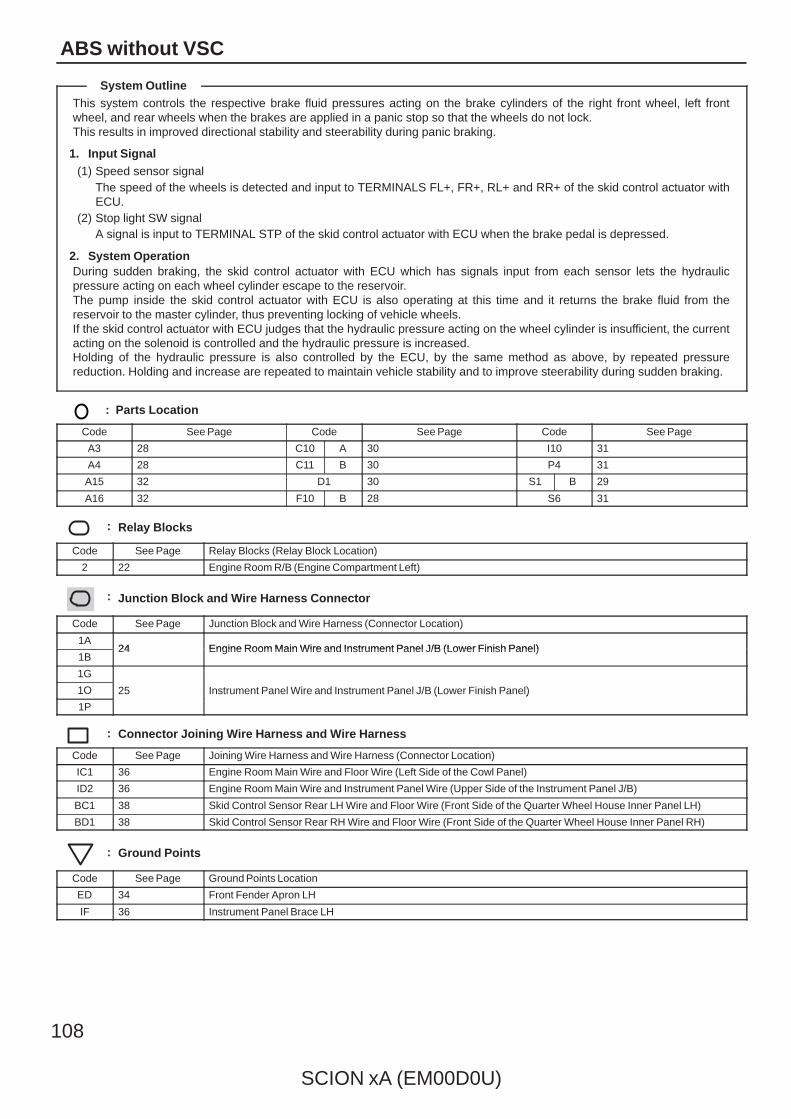
108
SCION xA (EM00D0U)
ABS without VSC
This system controls the respective brake fluid pressures acting on the brake cylinders of the right front wheel, left frontwheel, and rear wheels when the brakes are applied in a panic stop so that the wheels do not lock.This results in improved directional stability and steerability during panic braking.
1. Input Signal(1) Speed sensor signal
The speed of the wheels is detected and input to TERMINALS FL+, FR+, RL+ and RR+ of the skid control actuator withECU.
(2) Stop light SW signalA signal is input to TERMINAL STP of the skid control actuator with ECU when the brake pedal is depressed.
2. System OperationDuring sudden braking, the skid control actuator with ECU which has signals input from each sensor lets the hydraulicpressure acting on each wheel cylinder escape to the reservoir.The pump inside the skid control actuator with ECU is also operating at this time and it returns the brake fluid from thereservoir to the master cylinder, thus preventing locking of vehicle wheels.If the skid control actuator with ECU judges that the hydraulic pressure acting on the wheel cylinder is insufficient, the currentacting on the solenoid is controlled and the hydraulic pressure is increased.Holding of the hydraulic pressure is also controlled by the ECU, by the same method as above, by repeated pressurereduction. Holding and increase are repeated to maintain vehicle stability and to improve steerability during sudden braking.
: Parts Location
Code See Page Code See Page Code See Page
A3 28 C10 A 30 I10 31
A4 28 C11 B 30 P4 31
A15 32 D1 30 S1 B 29
A16 32 F10 B 28 S6 31
: Relay Blocks
Code See Page Relay Blocks (Relay Block Location)
2 22 Engine Room R/B (Engine Compartment Left)
: Junction Block and Wire Harness Connector
Code See Page Junction Block and Wire Harness (Connector Location)
1A24 Engine Room Main Wire and Instrument Panel J/B (Lower Finish Panel)
1B24 Engine Room Main Wire and Instrument Panel J/B (Lower Finish Panel)
1G
25 Instrument Panel Wire and Instrument Panel J/B (Lower Finish Panel)1O 25 Instrument Panel Wire and Instrument Panel J/B (Lower Finish Panel)
1P
25 Instrument Panel Wire and Instrument Panel J/B (Lower Finish Panel)
: Connector Joining Wire Harness and Wire Harness
Code See Page Joining Wire Harness and Wire Harness (Connector Location)
IC1 36 Engine Room Main Wire and Floor Wire (Left Side of the Cowl Panel)
ID2 36 Engine Room Main Wire and Instrument Panel Wire (Upper Side of the Instrument Panel J/B)
BC1 38 Skid Control Sensor Rear LH Wire and Floor Wire (Front Side of the Quarter Wheel House Inner Panel LH)
BD1 38 Skid Control Sensor Rear RH Wire and Floor Wire (Front Side of the Quarter Wheel House Inner Panel RH)
: Ground Points
Code See Page Ground Points Location
ED 34 Front Fender Apron LH
IF 36 Instrument Panel Brace LH
System Outline

SCION xA (EM00D0U)
109
SRS
NOTICE: When inspecting or repairing the SRS, perform service in accordance with the following precautionary instructionsand the procedure, and precautions in the Repair Manual applicable for the model year.
Malfunction symptoms of the SRS are difficult to confirm, so the DTCs become the most important source of informationwhen troubleshooting. When troubleshooting the SRS, always inspect the DTCs before disconnecting the battery.
Work must be started more than 90 seconds after the ignition SW is turned to the ”LOCK” position and thenegative (–) terminal cable is disconnected from the battery.(The SRS is equipped with a back–up power source so that if work is started within 90 seconds fromdisconnecting the negative (–) terminal cable of the battery, the SRS may deploy.)
When the negative (–) terminal cable is disconnected from the battery, the memory of the clock and audio system will becleared. So before starting work, make a record of the contents in the audio memory system. When work is finished,reset the audio systems as they were before and adjust the clock. Some vehicles have power tilt steering, powertelescopic steering, power seat and power outside rear view mirror which are all equipped with memory function.However, it is not possible to make a record of these memory contents. So when the work is finished, it will benecessary to explain it to your customer, and ask the customer to adjust the features and reset the memory. To avoiderasing the memory in each system, never use a back–up power supply from outside the vehicle.
Before repair, remove the airbag sensor if shocks are likely to be applied to the sensor during repair.
Do not expose the following parts directly to hot air or flame;
Even in cases of a minor collision where the SRS does not deploy, the following parts should be inspected;
Never use SRS parts from another vehicle. When replacing parts, replace with new parts.
For the purpose of reuse, never disassemble and repair the following parts.
If the following parts have been dropped, or have cracks, dents and other defects in their case, bracket, and connector,replace with new one.
Use a volt/ohmmeter with high impedance (10 kΩ/V minimum) for troubleshooting electrical circuits of the system.
Information labels are attached to the periphery of the SRS components. Follow the instructions of the notice.
After work on the SRS is completed, check the SRS warning light.
If the vehicle is equipped with a mobile communication system, refer to the precaution in the IN section of the RepairManual.
∗ Steering wheel pad∗ Front passenger airbag assembly∗ Side airbag assembly∗ Curtain shield airbag assembly∗ Seat belt pretensioner∗ Center airbag sensor assembly∗ Front airbag sensor assembly∗ Side airbag sensor assembly∗ Rear airbag sensor assembly
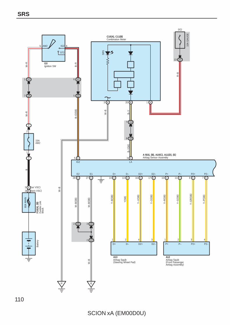
110
SCION xA (EM00D0U)
SRS
7 1A
1 1O
15AAM2
2
1
2
2
60A
MA
IN
1O6
1D5
C5
1D2 1D3
1O2
C28 C27
Bat
tery
BW
–RW
–R
B–O
( SB
)
I10
E2 E1
IG2
W–B
( SB
)
W–B
( SB
)
W–B
5 6AM2 IG2
ST2
F10(
A), (
B)
IE
B–R
7 C8 C11 C10 C17 C16 CC13
8 1D
7 1G
1 A20 B3 A
3 CA 9(A), (B), A10(C), A11(D), (E)
13 1G
C10(A), C11(B)
14 C
D2–D2+D–
A12
B–Y
( W)
LA
IF
D+
Y–V
( SB
)
Y–O
( SB
)
D2+ D2–
W–B
W–B
SR
S
B–Y
R–B
10A
GA
UG
E
Y–B
( SB
)
Y( S
B)
D+ D–
1 2 4 3
P2–P2+P–P+
Y–G
R( S
B)
Y–P
( SB
)
P2+ P2–
Y–R
( SB
)
Y–G
( SB
)P+ P–
1 2 3 4
A13Airbag Squib(Front PassengerAirbag Assembly)
Airbag Squib(Steering Wheel Pad)
Airbag Sensor Assembly
Combination MeterFu
sibl
e Li
nkB
lock
Ignition SW
(IG)
(w/o VSC)B2(w/ VSC)A3

SCION xA (EM00D0U)
111
23 C
1P3
1D4
1P5
1D1
C19 C12
TC SIL
13 7
D 1
P–B W
P–B
( W)
W( S
B)
TC SIL
B( S
B)
Y
32
E 6
1H10
1D9
F/PS
15 D D17
S 7
2 B8 A
5 E9 D
(∗2)1 B20 C9 C
2 ID1 1 ID1
A 6P16P15
A 9(A), (B), A10(C), A11(D), (E)
A 5
4 ID1 3 ID1
(∗1)7 A(∗2)
S10
C15 C
1
GSW2
26
+SL
2 1
W–R BR
W–R
( SB
)
BR
( SB
)
6 E
1 2 1 2
Y–B Y Y–B Y
PL+ PL– PR+ PR–
2
+SR –SR
B–W
( SB
)
BR
–W( S
B)
B–W
BR
–W
(∗1)10 D
∗ 2 : w/o Side Airbag∗ 1 : w/ Side Airbag
B
BBR–
3
BBR–
( ∗1) W
BBR+
4
BBR+
( ∗1)
B
BBL–
BBL–
( ∗1)
S 9
3
W
BBL+
BBL+
( ∗1)
4
BCR–
2
BCR+
1
2
BCL–
1
BCL+
( ∗1)
BCL–
1
R( ∗1)
BCL+
2
G
1
( ∗1)
BCR–
G
2
( ∗1)
BCR+
R
S 8
Airbag Sensor Assembly
Side Airbag SensorRear LH
Side Airbag SensorRear RH
Data Link Connector 3Engine ControlModule
Airbag SensorFront LH
Airbag SensorFront RH
Pretensioner LH Pretensioner RH
Side Airbag Sensor Front LH
Side Airbag Sensor Front RH
Note : Since there is a case where the different wire color is used depending on the vehicle, a wire color code like " G(SB)" is used in this manual. Please refer to page 40 for details.
(∗1)A18 (∗1)A16
–SL
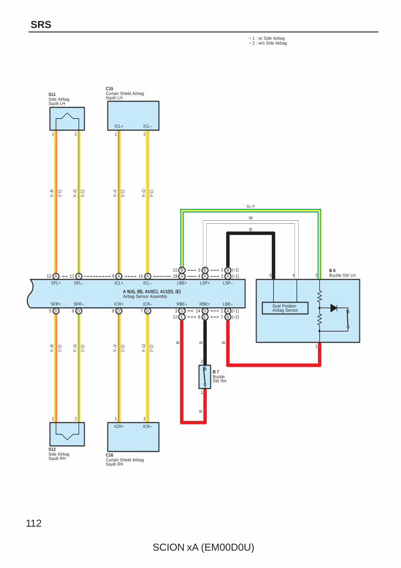
112
SCION xA (EM00D0U)
SRS
B11A19
B3 (∗2)A3 (∗1)
B
A2 (∗1)B7 (∗2)
43
AB 6
B 7
A12 A 9 A 10 A
5 D 6 D 8 D 7 D
A 9(A), (B), A10(C), A11(D), (E)
C15S11
S12C16
1 2
Y–R
Y–G
SFR+ SFR–
( ∗1)
( ∗1)
( ∗1)
ICR–ICR+
( ∗1)
21
ICR+ ICR–
Y–V
Y–O
Y–R
SFL+
( ∗1)
1
Y–G
SFL–
( ∗1)
2
( ∗1)
( ∗1)
ICL+ ICL–
Y–V
Y–O
1 2
ICL+
∗ 1 : w/ Side Airbag∗ 2 : w/o Side Airbag
LBE+ LSP+ LSP–
LBE–
1
1
5 4 2
B
W
G–Y
R
R
2
Seat PositionAirbag Sensor
B
D14E8
RBE+
ICL–
Buckle SW LH
BuckleSW RH
Airbag Sensor Assembly
Curtain Shield AirbagSquib LH
Curtain Shield AirbagSquib RH
Side AirbagSquib LH
Side AirbagSquib RH
D3E12
RBE–
R
11
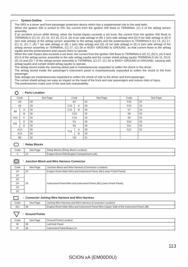
SCION xA (EM00D0U)
113
The SRS is a driver and front passenger protection device which has a supplemental role to the seat belts.When the ignition SW is turned to ON, the current from the ignition SW flows to TERMINAL (C) 5 of the airbag sensorassembly.If an accident occurs while driving, when the frontal impact exceeds a set level, the current from the ignition SW flows toTERMINALS (C) 14, (C) 16, (C) 10, (C) 8, (A) 8 (w/ side airbag) or (B) 2 (w/o side airbag) and (D) 9 (w/ side airbag) or (E) 5(w/o side airbag) of the airbag sensor assembly to the airbag squibs and the pretensioners to TERMINALS (C) 13, (C) 17,(C) 11, (C) 7, (A) 7 (w/ side airbag) or (B) 1 (w/o side airbag) and (D) 10 (w/ side airbag) or (E) 6 (w/o side airbag) of theairbag sensor assembly to TERMINAL (C) 27, (C) 28 or BODY GROUND to GROUND, so that current flows to the airbagsquibs and the pretensioners and causes them to operate.When the side impact also exceeds a set level, the current from the ignition SW flows to TERMINALS (A) 12, (D) 5, (A) 9 and(D) 8 of the airbag sensor assembly to the side airbag squibs and the curtain shield airbag squibs TERMINALS (A) 11, (D) 6,(A) 10 and (D) 7 of the airbag sensor assembly to TERMINAL (C) 27, (C) 28 or BODY GROUND to GROUND, causing sideairbag squibs and curtain shield airbag squibs to operate.The airbag stored inside the steering wheel pad is instantaneously expanded to soften the shock to the driver.The airbag stored inside the passenger’s instrument panel is instantaneously expanded to soften the shock to the frontpassenger.Side airbags are instantaneously expanded to soften the shock of side to the driver and front passenger.The curtain shield airbag can ease an impact on the head of the front and rear passengers and reduce risks of injury.The pretensioners make sure of the seat belt restrainability.
: Parts Location
Code See Page Code See Page Code See Page
A5 28 B7 32 P15 33
A6 28 C10 A 30 P16 33
A9A 30 C11 B 30 S7 33
A9B 30 C15 32 S8 33
A10 C 30 C16 32 S9 33
A11D 30 D1 30 S10 33
A11E 30 E6 30 S11 33
A12 30F10
A 28 S12 33
A13 30F10
B 28
B6 32 I10 31
: Relay Blocks
Code See Page Relay Blocks (Relay Block Location)
2 22 Engine Room R/B (Engine Compartment Left)
: Junction Block and Wire Harness Connector
Code See Page Junction Block and Wire Harness (Connector Location)
1A 24 Engine Room Main Wire and Instrument Panel J/B (Lower Finish Panel)
1D
25 Instrument Panel Wire and Instrument Panel J/B (Lower Finish Panel)
1G
25 Instrument Panel Wire and Instrument Panel J/B (Lower Finish Panel)1H 25 Instrument Panel Wire and Instrument Panel J/B (Lower Finish Panel)
1O
25 Instrument Panel Wire and Instrument Panel J/B (Lower Finish Panel)
1P
: Connector Joining Wire Harness and Wire Harness
Code See Page Joining Wire Harness and Wire Harness (Connector Location)
ID1 36 Engine Room Main Wire and Instrument Panel Wire (Upper Side of the Instrument Panel J/B)
: Ground Points
Code See Page Ground Points Location
IE 36 Left Kick Panel
IF 36 Instrument Panel Brace LH
System Outline
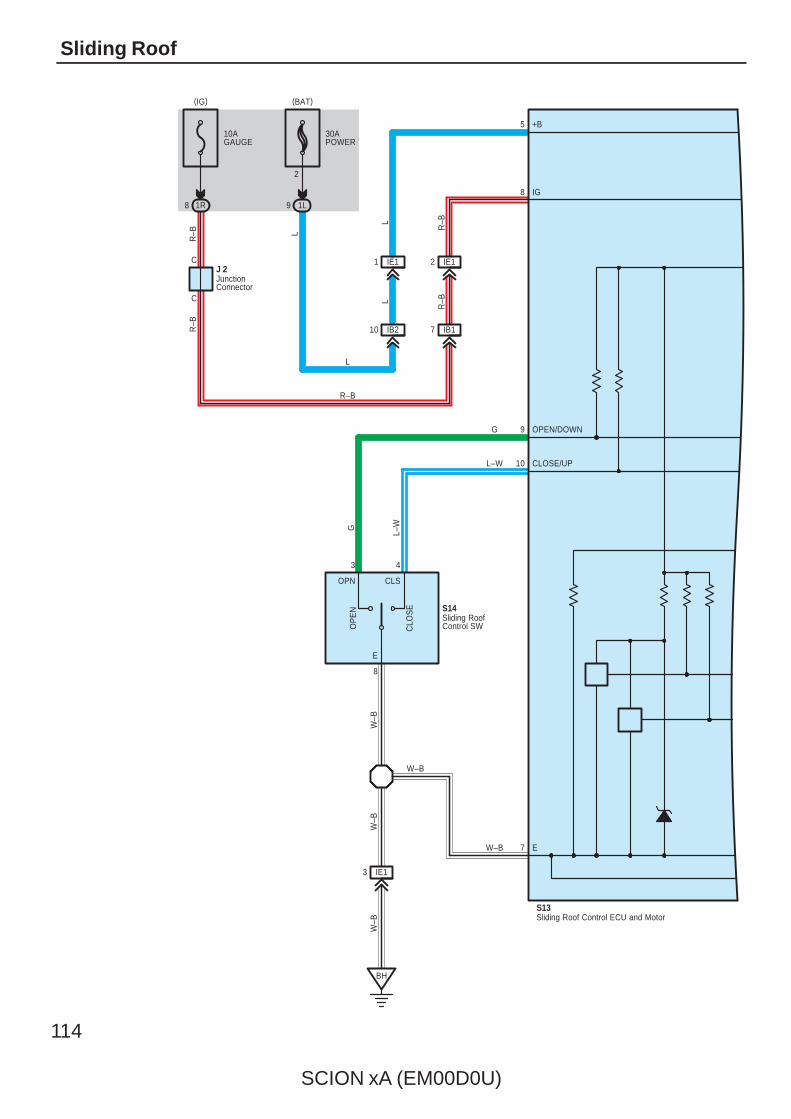
114
SCION xA (EM00D0U)
Sliding Roof
2
30APOWER
1L
S14
C
C
4
CLS
E
8
OP
EN
CLO
SE
OPN
3
R–B
J 2
8 1R
10AGAUGE
R–B
9
+B
IG
OPEN/DOWN
CLOSE/UP
E7
10
9
8
5
BH
IE13
W–B
L–W
G
W–B
W–B
W–B
W–B
G
L–W
IE12
IB17
IE11
IB210
L
R–B
R–BL
L
L
R–B
S13
JunctionConnector
Sliding Roof Control ECU and Motor
Sliding RoofControl SW
(BAT)(IG)
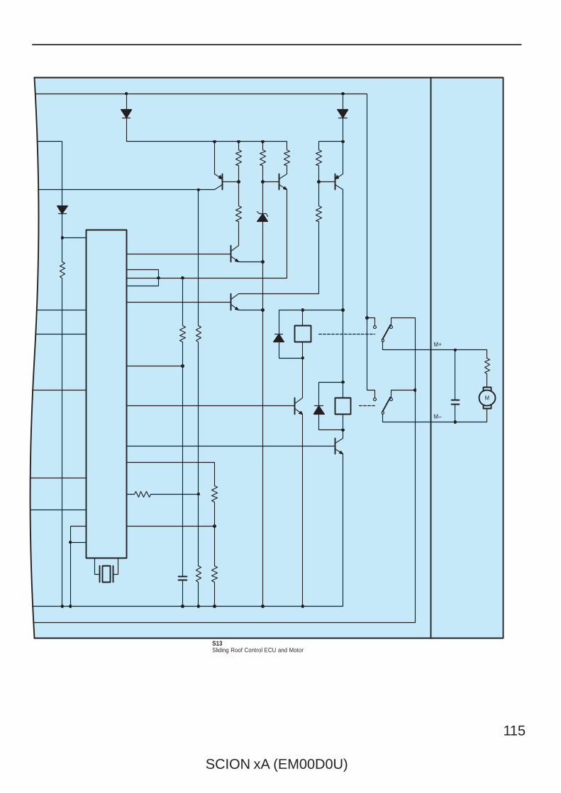
SCION xA (EM00D0U)
115
M
M–
M+
S13Sliding Roof Control ECU and Motor

116
SCION xA (EM00D0U)
Sliding Roof
The sliding roof can be operated when the ignition SW is turned to ON position.
1. Slide Open OperationThe sliding roof fully opens automatically by pressing the OPEN button of the sliding roof control SW once. The sliding roofopens half and stops the operation once. If the sliding roof control switch is pressed again when the sliding roof is operating,the movement of the sliding roof stops.
2. Slide Close OperationIf you keep pressing the CLOSE button of the sliding roof control SW when the sliding roof is closes.
3. Tilt Up OperationIf you press the CLOSE button of the sliding roof control SW, the sliding roof is tilted up. However, the sliding roof is not tiltedup when it is open
4. Tilt Down OperationIf you press the OPEN button when the TILT UP of the sliding roof control SW is pressed, the sliding roof is tilted down.
: Parts Location
Code See Page Code See Page Code See Page
J2 31 S13 33 S14 33
: Junction Block and Wire Harness Connector
Code See Page Junction Block and Wire Harness (Connector Location)
1L25 Instrument Panel Wire and Instrument Panel J/B (Lower Finish Panel)
1R25 Instrument Panel Wire and Instrument Panel J/B (Lower Finish Panel)
: Connector Joining Wire Harness and Wire Harness
Code See Page Joining Wire Harness and Wire Harness (Connector Location)
IB136 Floor Wire and Instrument Panel Wire (Upper Side of the Instrument Panel J/B)
IB236 Floor Wire and Instrument Panel Wire (Upper Side of the Instrument Panel J/B)
IE1 37 Roof Wire and Floor Wire (Upper Side of the Cowl Side Panel LH)
: Ground Points
Code See Page Ground Points Location
BH 38 Left Quarter Pillar
System Outline

SCION xA (EM00D0U)
117
Memo
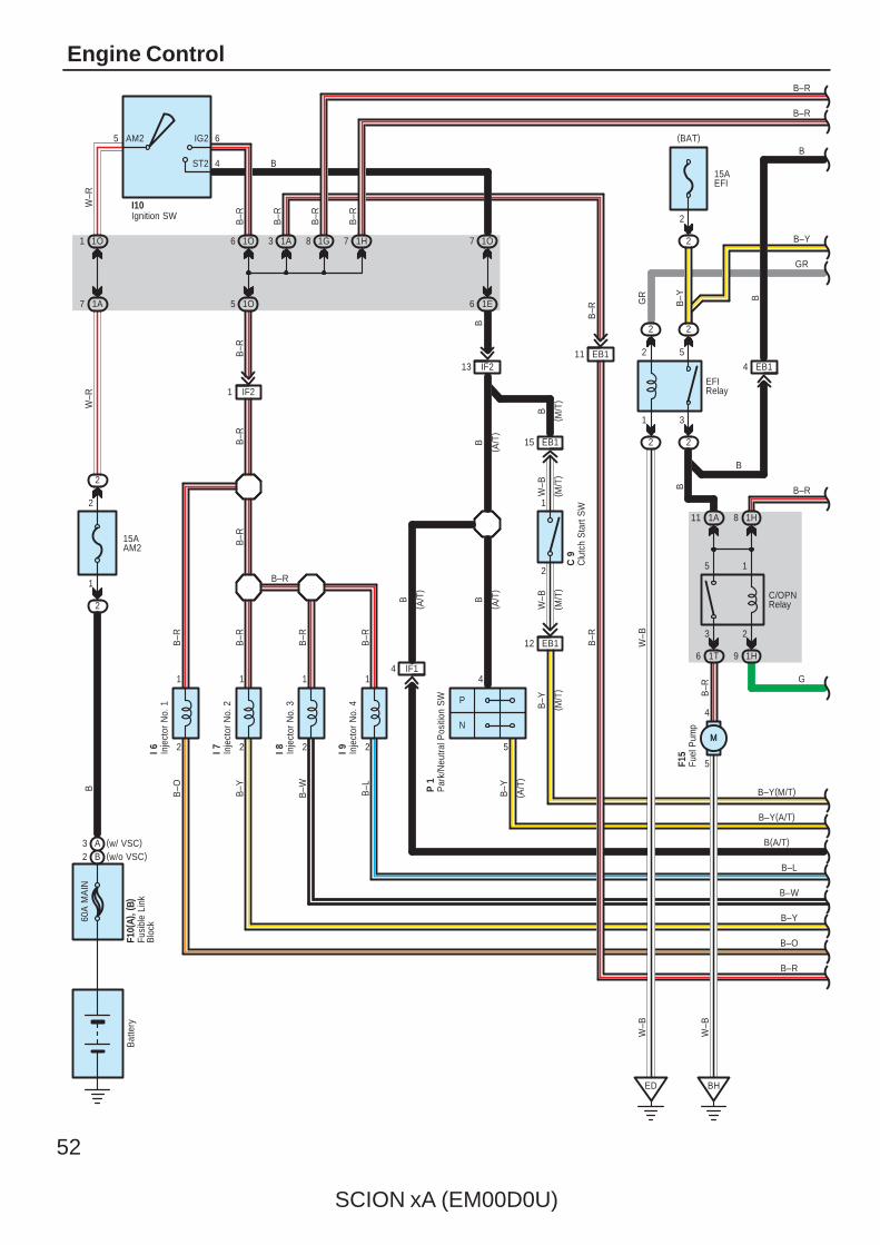
52
SCION xA (EM00D0U)
Engine Control60
A M
AIN
15AAM2
2
1
2
2
1O1
1A7
5 6
4
AM2 IG2
ST2
1O6
1O5
3 1A
BW
–RW
–R
B–R
B–R
B–R
IF21
B–R
B–R
2
1
B–Y
I 7
B–R
2
1
B–W
I 8
B–R
2
1
B–L
I 9
B–R
2
1
B–O
I 6
7 1O
B
6 1E
B
BB
P
N
4
2
5
B–Y
( A/T
)
( A/T
)
( A/T
)
B–Y
( M/T
)
15AEFI
2
1 3
2 5
2 2
2 2
W–B
ED
W–B
B–Y
B–Y
B–Y(A/T)
B(A/T)
B–L
B–W
B–Y
B–O
B
B–R
F10(
A), (
B)
I10
B
3 2
5 1
1A11 1H8
1T6 1H9
B–R
5
4
BH
EB1411 EB1
13 IF2
B
W–B
F15
Bat
tery
C/OPNRelay
EFIRelay
P 1
B
GR
B–R
B–R
B–R
B–R
G
( A/T
)
B–Y(M/T)
EB115
2
1
C 9
EB112
B
( M/T
)
W–B
( M/T
)
W–B
( M/T
)
7 1H
B–R
B–R
Clu
tch
Sta
rt S
W
Fusi
ble
Link
Blo
ck
Fuel
Pum
p
Inje
ctor
No.
1
Inje
ctor
No.
2
Inje
ctor
No.
3
Inje
ctor
No.
4
Ignition SW
Par
k/N
eutra
l Pos
ition
SW
B–R
M
(BAT)
8 1G
B–R
IF14
GR
B–R
(w/o VSC)B2(w/ VSC)A3
B
M
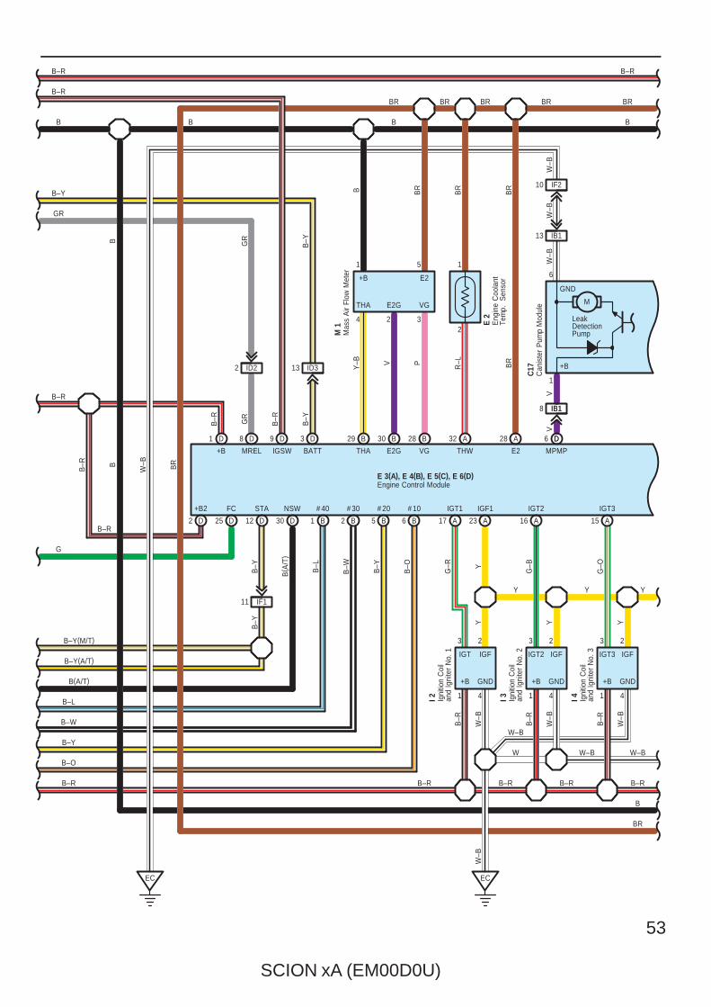
SCION xA (EM00D0U)
53
B–Y
B–L
B–W
B–Y
B–O
D25
FC
D12
STA
D1
+B
GR
GR
B29
THA
B30
E2G
B28
VGMREL
8 D
4 2 3
1 5
THW
32 A A28
E2
E 2
D30
NSW
B1
# 40
B2
# 30
B5
# 20
B6
# 10
B–OB–Y
B–WB–L
B( A
/T)
Y–B V P R–L BR
BR
BR
B
IGT3
A15
B B
BR BR
GR
B–R
B–R
17 A 23 A
IGT1 IGF1
16 A
IGT2
EC
2323
I 2 I 3
GND
B
W–B
+B
I 4
3 2
1 4 1 4 1 4
Y Y
W–BW
B–R B–RB–R
G–R Y
G–B
G–O
YYYW
–B
B–R
W–B
B–R
W–B
B–R
W–B
+B
BR
M 1
+B E2
THA E2G VG
G
BR
BR
BR
GND
B–R B–R
E 3(A), E 4(B), E 5(C), E 6(D)
+B GND
IGT IGF IGT2 IGF IGT3 IGF
Eng
ine
Coo
lant
Tem
p.
Sen
sor
Engine Control Module
Igni
tion
Coi
lan
d Ig
nite
r N
o. 1
Igni
tion
Coi
lan
d Ig
nite
r N
o. 2
Igni
tion
Coi
lan
d Ig
nite
r N
o. 3
Mas
s A
ir Fl
ow M
eter
B–Y(A/T)
B(A/T)
B–Y(M/T)
D2
+B2
MPMP
D6
IB18
V
D
IB1
V
10 IF2
IB113
W–B
W–B
W–B
2
1
13 ID3
B–Y
BATT
3 D
B–R
IGSW
9 D
B–Y
EC
B–R
B–R B
W–B BR
B–R
IF111
ID22
B
B
BR
B
B–R
B–Y
B–Y
Y
W–B
B–R
1
+B
M
LeakDetectionPump
C17
Can
iste
r P
ump
Mod
ule
6
GND

54
SCION xA (EM00D0U)
Engine Control
VPMP
BR
14 A
IGT4
I 5
E2
VC PSS
T 1
PSP
32 B
1
3 2
BR
Y–R
VTA1
20 A
VC
18 A
R–W
R–W
2
3 1
BR
3 2
1 4
Y
G–Y
Y
B–R
D5
R–W
8 IF1IB11
IB19
20 IF2
IB114
BB
BP
R–W
P
R–W
9
R–W Y
W–B
VTA
E2
VC
+B GND
IGT4 IGF
Igni
tion
Coi
lan
d Ig
nite
r N
o. 4
Thro
ttle
Pos
ition
Sen
sor
10ASTOP
1B8
1
2
C4
STP
G–W
1B2
1H2
G–B
G–W
32
1
BB
–R
A5
RSD
A3
E1
A1
HT1A
42
1 3
A21
OX1A
A2
HT1B
42
1 3
A25
OX1B
LL
W
B–RBR
B BR
BR B B
R
I 1
H 3
H 6
KNK1
29 A
1 EA1
W
( ∗1)
W
( ∗1)
( ∗1)
( ∗1)
S 6
B
BR
B
B23
PRG
W–G
2
1
B
B
B
IF113 IF114
IF12
1 IF1
W
(∗1)
B GND
RSD HT1A OX1A HT1B OX1B
+B E2 +B E2
W
(∗1)
BR
BR
BR
BR BR
( ∗1)
BRBR
B–R B–R
E 3(A), E 4(B), E 5(C), E 6(D)Engine Control Module
Hea
ted
Oxy
gen
Sen
sor
( Ban
k 1
Sen
sor
1)
Hea
ted
Oxy
gen
Sen
sor
( Ban
k 1
Sen
sor
2)
Idle
Air
Con
trol V
alve
Sto
p Li
ght S
W
(BAT)
EKNK
30 A
2 EA1
BB
WW
IF19
Pow
er S
teer
ing
Oil
Pre
ssur
e S
enso
r
P 2
PPMP
D31
IB110
RR
7 IF1
IB112
BR
BR
BR
2
7 IF1
IB1
B
BR
VS
V (
Pur
ge)
P17
W–B
B–R
Can
iste
r P
ump
Mod
ule
C17
Ven
t Val
ve
+B
GND
8
Canister PressureSensor
SGND
3
VOUT
4
VCC
2 1
Knock Sensor(Bank 1)
K 1
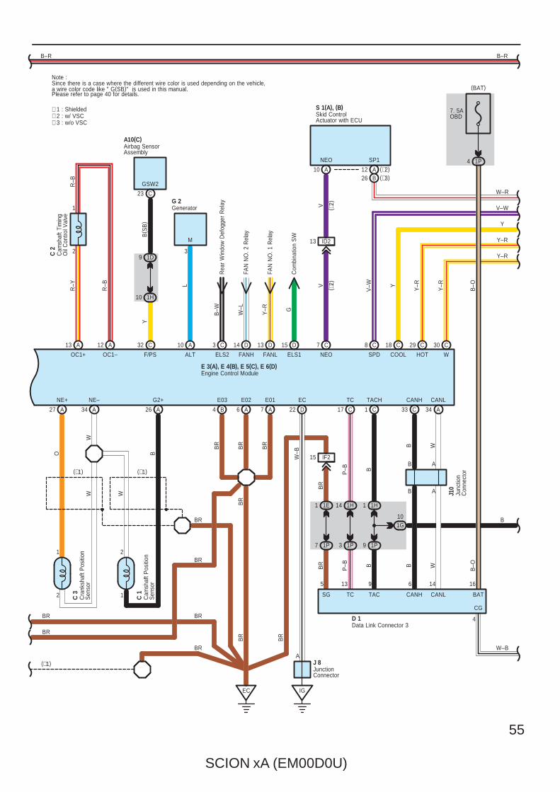
SCION xA (EM00D0U)
55
G
A10(C)
A13
OC1+
A12
OC1–
A10
ALT
2
1
R–Y
R–B L
M
R–B
3
A27
NE+
A34
NE–
WW
O
2
1
C 3 1
2
C 1
A26
G2+
W
B
BR
C 2
B4
E03
A6
E02
A7
E01
BR
BR
BR
EC
C17
TC
P–B
1H14
1P3
P–B
13
BR
BR
BR
B( S
B)
C8
SPD HOT
29 C
COOL
18 C
V–W
16
1P4
4
CG
BAT
B–O
Y–R
Y–R
Y
V–W
B–O
G 2
D 1
TC
C30
W
IF215
BR
1E1
1P7
BR
5
SG
FANH
D14
FAN
NO
. 2 R
elay
W–L
BR
Y–R
FANL
FAN
NO
. 1 R
elay
13 D
(∗1) (∗1)
1D9
1H10
C32
F/PS
Y
CANL
34 A
14
W
CANL
BR
(∗1)
W–B
B1G10
W
B–R B–R
GSW2
ELS1
Com
bina
tion
SW
15 D
ID213
V
NEO
7 C
NEO
V ( ∗2)
S 1(A), (B)
( ∗2) Y
Y–R
Y–R
E 3(A), E 4(B), E 5(C), E 6(D)
A
A
J10
Skid ControlActuator with ECU
Cam
shaf
t Pos
ition
Sen
sor
Cra
nksh
aft P
ositi
onS
enso
r
Airbag SensorAssembly
Cam
shaf
t Tim
ing
Oil
Con
trol V
alve
Data Link Connector 3
Engine Control Module
Generator
Junc
tion
Con
nect
or
Note : Since there is a case where the different wire color is used depending on the vehicle, a wire color code like " G(SB)" is used in this manual.
W–R
SP1
(BAT)
BR
BR
(∗2)A12(∗3)B26
CANH
33 C
6
B
CANH
B
B
B
TACH
1 C
1H1
B
1P9
B
9
TAC
IG
JunctionConnector
J 8A
D22
EC
W–B
∗ 1 : Shielded∗ 2 : w/ VSC∗ 3 : w/o VSC
7. 5AOBD
A10
ELS2
C3
Rea
r W
indo
w D
efog
ger
Rel
ayB
–W
C23
BR
Please refer to page 40 for details.
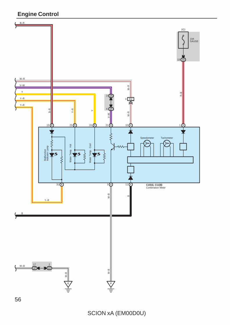
56
SCION xA (EM00D0U)
Engine Control
23 B 24 B
B31 A3
Y–R
W–B
Y–R
1G13
W–B
IE
A
W–B
IF
Speedometer
B21
1F6
1H3
V–W
13 B
Wat
er T
emp.
H
ot
Wat
er T
emp.
C
ool
Y–R
Y
V–W
W–B
10
B
A11
B
Tachometer
Mal
func
tion
Indi
cato
r La
mp
B–R
B–R
Y–R Y
ID23
W–R
W–R
R–B
A1
C10(A), C11(B)Combination Meter
W–R
(IG)
10AGAUGE
21O
171P
SCION xA (EM00D0U)
57
This system utilizes an engine control module and maintains overall control of the engine, transmission and so on. An outlineof the engine control is explained here.
1. Input Signals(1) Engine coolant temp. signal circuit
The engine coolant temp. sensor detects the engine coolant temp. and has a built–in thermistor with a resistance whichvaries according to the engine coolant temp. thus the engine coolant temp. is input in the form of a control signal intoTERMINAL THW of the engine control module.
(2) Intake air temp. signal circuitThe intake air temp. sensor is installed in the mass air flow meter and detects the intake air temp., which is input as acontrol signal into TERMINAL THA of the engine control module.
(3) Oxygen sensor signal circuitThe oxygen density in the exhaust gases is detected and input as a control signal into TERMINALS OX1A and OX1B ofthe engine control module.
(4) RPM signal circuitCamshaft position and crankshaft position are detected by the camshaft position sensor and crankshaft position sensor.Camshaft position is input as a control signal to TERMINAL G2+ of the engine control module, and engine RPM is inputinto TERMINAL NE+.
(5) Throttle signal circuitThe throttle position sensor detects the throttle valve opening angle, which is input as a control signal into TERMINALVTA1 of the engine control module.
(6) Vehicle speed signal circuitThe vehicle speed sensor detects the vehicle speed, and the signal is input into TERMINAL SPD of the engine controlmodule via the combination meter, from TERMINAL SP1 of the skid control actuator with ECU.
(7) NSW signal circuit (A/T)The Park/Neutral position SW detects whether the shift position are in neutral, parking or not, and inputs a control signalinto TERMINAL NSW of the engine control module.
(8) Battery signal circuitVoltage is constantly applied to TERMINAL BATT of the engine control module. When the ignition SW is turned on, thevoltage for engine control module start–up power supply is applied to TERMINAL +B of the engine control module viaEFI relay.
(9) Starter signal circuitTo confirm whether the engine is cranking, the voltage applied to the starter motor during cranking is detected and thesignal is input into TERMINAL STA of the engine control module as a control signal.
System Outline
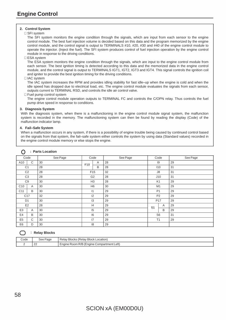
58
SCION xA (EM00D0U)
Engine Control
2. Control System∗ SFI system
The SFI system monitors the engine condition through the signals, which are input from each sensor to the enginecontrol module. The best fuel injection volume is decided based on this data and the program memorized by the enginecontrol module, and the control signal is output to TERMINALS #10, #20, #30 and #40 of the engine control module tooperate the injector. (Inject the fuel). The SFI system produces control of fuel injection operation by the engine controlmodule in response to the driving conditions.
∗ ESA systemThe ESA system monitors the engine condition through the signals, which are input to the engine control module fromeach sensor. The best ignition timing is detected according to this data and the memorized data in the engine controlmodule, and the control signal is output to TERMINALS IGT1, IGT2, IGT3 and IGT4. This signal controls the ignition coiland igniter to provide the best ignition timing for the driving conditions.
∗ IAC systemThe IAC system increases the RPM and provides idling stability for fast idle–up when the engine is cold and when theidle speed has dropped due to electrical load, etc. The engine control module evaluates the signals from each sensor,outputs current to TERMINAL RSD, and controls the idle air control valve.
∗ Fuel pump control systemThe engine control module operation outputs to TERMINAL FC and controls the C/OPN relay. Thus controls the fuelpump drive speed in response to conditions.
3. Diagnosis SystemWith the diagnosis system, when there is a malfunctioning in the engine control module signal system, the malfunctionsystem is recorded in the memory. The malfunctioning system can then be found by reading the display (Code) of themalfunction indicator lamp.
4. Fail–Safe SystemWhen a malfunction occurs in any system, if there is a possibility of engine trouble being caused by continued control basedon the signals from that system, the fail–safe system either controls the system by using data (Standard values) recorded inthe engine control module memory or else stops the engine.
: Parts Location
Code See Page Code See Page Code See Page
A10 C 30F10
A 28 I9 29
C1 28F10
B 28 I10 31
C2 28 F15 32 J8 31
C3 28 G2 28 J10 31
C9 30 H3 28 K1 29
C10 A 30 H6 30 M1 29
C11 B 30 I1 29 P1 29
C17 32 I2 29 P2 29
D1 30 I3 29 P17 29
E2 28 I4 29S1
A 29
E3 A 30 I5 29S1
B 29
E4 B 30 I6 29 S6 31
E5 C 30 I7 29 T1 29
E6 D 30 I8 29
: Relay Blocks
Code See Page Relay Blocks (Relay Block Location)
2 22 Engine Room R/B (Engine Compartment Left)
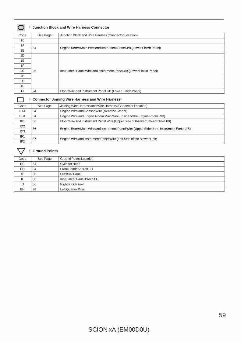
SCION xA (EM00D0U)
59
: Junction Block and Wire Harness Connector
Code See Page Junction Block and Wire Harness (Connector Location)
10
1A24 Engine Room Main Wire and Instrument Panel J/B (Lower Finish Panel)
1B24 Engine Room Main Wire and Instrument Panel J/B (Lower Finish Panel)
1D
25 Instrument Panel Wire and Instrument Panel J/B (Lower Finish Panel)
1E
25 Instrument Panel Wire and Instrument Panel J/B (Lower Finish Panel)
1F
25 Instrument Panel Wire and Instrument Panel J/B (Lower Finish Panel)1G 25 Instrument Panel Wire and Instrument Panel J/B (Lower Finish Panel)
1H
25 Instrument Panel Wire and Instrument Panel J/B (Lower Finish Panel)
1O
1P
1T 24 Floor Wire and Instrument Panel J/B (Lower Finish Panel)
: Connector Joining Wire Harness and Wire Harness
Code See Page Joining Wire Harness and Wire Harness (Connector Location)
EA1 34 Engine Wire and Sensor Wire (Near the Starter)
EB1 34 Engine Wire and Engine Room Main Wire (Inside of the Engine Room R/B)
IB1 36 Floor Wire and Instrument Panel Wire (Upper Side of the Instrument Panel J/B)
ID236 Engine Room Main Wire and Instrument Panel Wire (Upper Side of the Instrument Panel J/B)
ID336 Engine Room Main Wire and Instrument Panel Wire (Upper Side of the Instrument Panel J/B)
IF137 Engine Wire and Instrument Panel Wire (Left Side of the Blower Unit)
IF237 Engine Wire and Instrument Panel Wire (Left Side of the Blower Unit)
: Ground Points
Code See Page Ground Points Location
EC 34 Cylinder Head
ED 34 Front Fender Apron LH
IE 36 Left Kick Panel
IF 36 Instrument Panel Brace LH
IG 36 Right Kick Panel
BH 38 Left Quarter Pillar
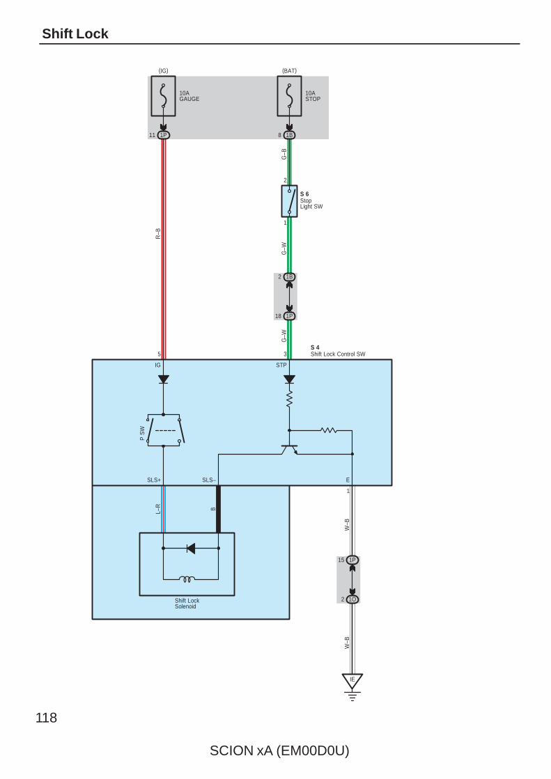
118
SCION xA (EM00D0U)
Shift Lock
11 1P
10AGAUGE
10ASTOP
1B8
1
2
1B2
1P18
R–B
G–B
1P15
1O2
IE
G–W
G–W
L–R B
W–B
W–B
5 3
1
IG STP
SLS+ SLS– E
S 6
S 4
Shift LockSolenoid
P S
W
Shift Lock Control SW
StopLight SW
(BAT)(IG)
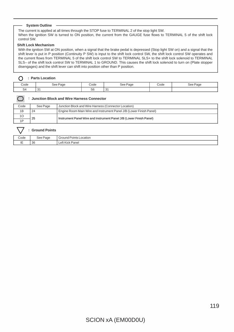
SCION xA (EM00D0U)
119
The current is applied at all times through the STOP fuse to TERMINAL 2 of the stop light SW.When the ignition SW is turned to ON position, the current from the GAUGE fuse flows to TERMINAL 5 of the shift lockcontrol SW.
Shift Lock MechanismWith the ignition SW at ON position, when a signal that the brake pedal is depressed (Stop light SW on) and a signal that theshift lever is put in P position (Continuity P SW) is input to the shift lock control SW, the shift lock control SW operates andthe current flows from TERMINAL 5 of the shift lock control SW to TERMINAL SLS+ to the shift lock solenoid to TERMINALSLS– of the shift lock control SW to TERMINAL 1 to GROUND. This causes the shift lock solenoid to turn on (Plate stopperdisengages) and the shift lever can shift into position other than P position.
: Parts Location
Code See Page Code See Page Code See Page
S4 31 S6 31
: Junction Block and Wire Harness Connector
Code See Page Junction Block and Wire Harness (Connector Location)
1B 24 Engine Room Main Wire and Instrument Panel J/B (Lower Finish Panel)
1O25 Instrument Panel Wire and Instrument Panel J/B (Lower Finish Panel)
1P25 Instrument Panel Wire and Instrument Panel J/B (Lower Finish Panel)
: Ground Points
Code See Page Ground Points Location
IE 36 Left Kick Panel
System Outline
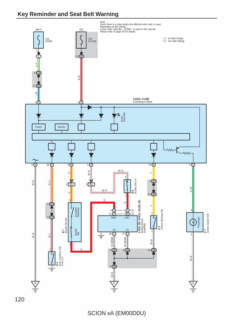
120
SCION xA (EM00D0U)
Key Reminder and Seat Belt Warning
Power Buzzer
Driv
erS
eat B
elt
B25A3 B8 B6 A6B18
A7 A1
IF
1G4
1S1
1
3
IB12 IB13
1
Occ
upan
tD
etec
tion
Buc
kle
SW
IE
1O2
1D2 1D3
C28 27 C
B7A2
3
1P
asse
nger
1
9
IG
1F1
1P19
1
2
1P16
D 4
B 7
A 9(
A), (
B), A
10( C
) , A1
1(D
) , ( E
)
U 1
C 7
B 6
O
W–R
R–Y
W–B
R–L
W–B
W–B
O
R
YY
G–W
W–B
( SB
)
W–B
( SB
)
W–B
W–B
W–R
(∗1)(∗2)
E2 E1
LBE–
C10(A), C11(B)
15ADOME
2
2
L–Y
10AGAUGE
1G13
1A4
1G12
L–B
R–B
∗ 2 : w/o Side Airbag∗ 1 : w/ Side Airbag
Buc
kle
SW
LH
Buc
kle
SW
RH
Airb
ag S
enso
rA
ssem
bly
Cen
ter
Clu
ster
SW
Combination Meter
Doo
r C
ourte
sy S
WFr
ont L
H
Unl
ock
War
ning
SW
Note : Since there is a case where the different wire color is useddepending on the vehicle, a wire color code like " G(SB)" is used in this manual. Please refer to page 40 for details.
E12D3
RBE–
R
R
W–R
(IG)(BAT)
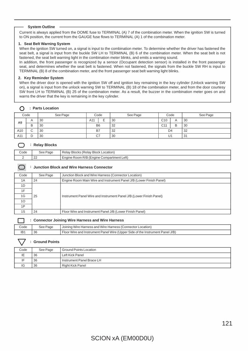
SCION xA (EM00D0U)
121
Current is always applied from the DOME fuse to TERMINAL (A) 7 of the combination meter. When the ignition SW is turnedto ON position, the current from the GAUGE fuse flows to TERMINAL (A) 1 of the combination meter.
1. Seat Belt Warning SystemWhen the ignition SW turned on, a signal is input to the combination meter. To determine whether the driver has fastened theseat belt, a signal is input from the buckle SW LH to TERMINAL (B) 6 of the combination meter. When the seat belt is notfastened, the seat belt warning light in the combination meter blinks, and emits a warning sound.In addition, the front passenger is recognized by a sensor (Occupant detection sensor) is installed in the front passengerseat, and determines whether the seat belt is fastened. When not fastened, the signals from the buckle SW RH is input toTERMINAL (B) 8 of the combination meter, and the front passenger seat belt warning light blinks.
2. Key Reminder SystemWhen the driver door is opened with the ignition SW off and ignition key remaining in the key cylinder (Unlock warning SWon), a signal is input from the unlock warning SW to TERMINAL (B) 18 of the combination meter, and from the door courtesySW front LH to TERMINAL (B) 25 of the combination meter. As a result, the buzzer in the combination meter goes on andwarns the driver that the key is remaining in the key cylinder.
: Parts Location
Code See Page Code See Page Code See Page
A9A 30 A11 E 30 C10 A 30
A9B 30 B6 32 C11 B 30
A10 C 30 B7 32 D4 32
A11 D 30 C7 30 U1 31
: Relay Blocks
Code See Page Relay Blocks (Relay Block Location)
2 22 Engine Room R/B (Engine Compartment Left)
: Junction Block and Wire Harness Connector
Code See Page Junction Block and Wire Harness (Connector Location)
1A 24 Engine Room Main Wire and Instrument Panel J/B (Lower Finish Panel)
1D
25 Instrument Panel Wire and Instrument Panel J/B (Lower Finish Panel)
1F
25 Instrument Panel Wire and Instrument Panel J/B (Lower Finish Panel)1G 25 Instrument Panel Wire and Instrument Panel J/B (Lower Finish Panel)
1O
25 Instrument Panel Wire and Instrument Panel J/B (Lower Finish Panel)
1P
1S 24 Floor Wire and Instrument Panel J/B (Lower Finish Panel)
: Connector Joining Wire Harness and Wire Harness
Code See Page Joining Wire Harness and Wire Harness (Connector Location)
IB1 36 Floor Wire and Instrument Panel Wire (Upper Side of the Instrument Panel J/B)
: Ground Points
Code See Page Ground Points Location
IE 36 Left Kick Panel
IF 36 Instrument Panel Brace LH
IG 36 Right Kick Panel
System Outline
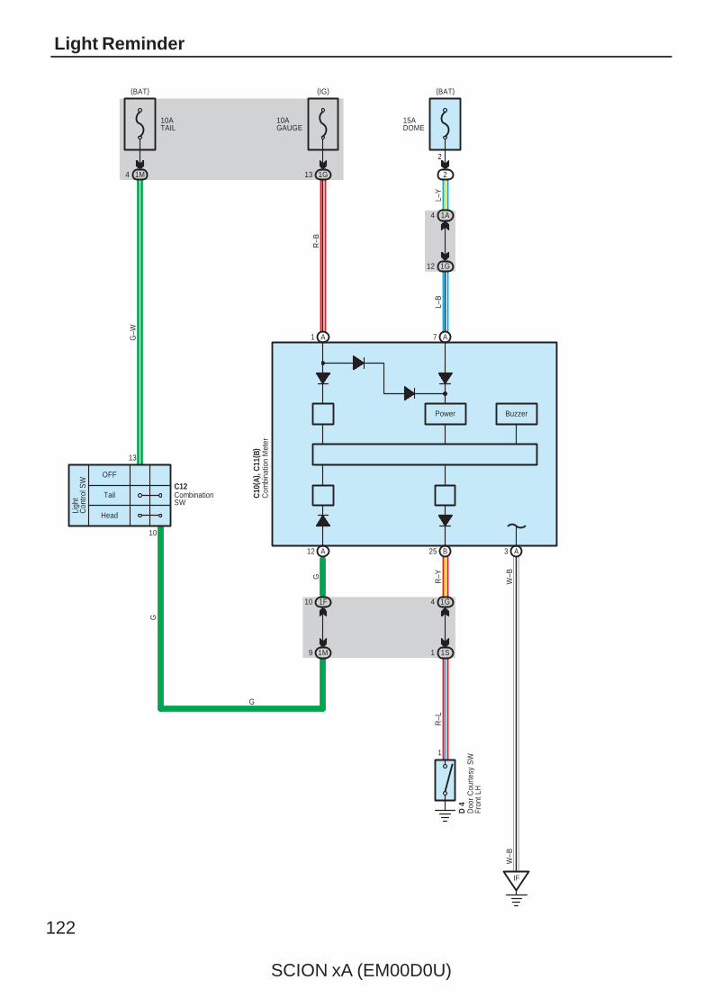
122
SCION xA (EM00D0U)
Light Reminder
10
10ATAIL
1M4
15ADOME
2
OFF
Tail
Head
9 1M
10 1F
B25A12 A3
A7
L–B
13
C10
( A) ,
C11
( B)
IF
1G4
1S1
1
G–W
L–Y
R–YG
W–B
R–L
W–B
Power
D 4
A1
10AGAUGE
1G13
R–B
2
1A4
1G12
Buzzer
C12
G
G
Ligh
tC
ontro
l SW
Com
bina
tion
Met
er
CombinationSW
Doo
r C
ourte
sy S
WFr
ont L
H
(BAT)(IG)(BAT)
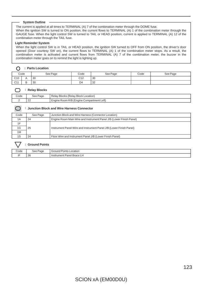
SCION xA (EM00D0U)
123
The current is applied at all times to TERMINAL (A) 7 of the combination meter through the DOME fuse.When the ignition SW is turned to ON position, the current flows to TERMINAL (A) 1 of the combination meter through theGAUGE fuse. When the light control SW is turned to TAIL or HEAD position, current is applied to TERMINAL (A) 12 of thecombination meter through the TAIL fuse.
Light Reminder SystemWhen the light control SW is in TAIL or HEAD position, the ignition SW turned to OFF from ON position, the driver’s dooropened (Door courtesy SW on), the current flows to TERMINAL (A) 1 of the combination meter stops. As a result, thecombination meter is activated and current flows from TERMINAL (A) 7 of the combination meter, the buzzer in thecombination meter goes on to remind the light is lighting up.
: Parts Location
Code See Page Code See Page Code See Page
C10 A 30 C12 30
C11 B 30 D4 32
: Relay Blocks
Code See Page Relay Blocks (Relay Block Location)
2 22 Engine Room R/B (Engine Compartment Left)
: Junction Block and Wire Harness Connector
Code See Page Junction Block and Wire Harness (Connector Location)
1A 24 Engine Room Main Wire and Instrument Panel J/B (Lower Finish Panel)
1F
25 Instrument Panel Wire and Instrument Panel J/B (Lower Finish Panel)1G 25 Instrument Panel Wire and Instrument Panel J/B (Lower Finish Panel)
1M
25 Instrument Panel Wire and Instrument Panel J/B (Lower Finish Panel)
1S 24 Floor Wire and Instrument Panel J/B (Lower Finish Panel)
: Ground Points
Code See Page Ground Points Location
IF 36 Instrument Panel Brace LH
System Outline
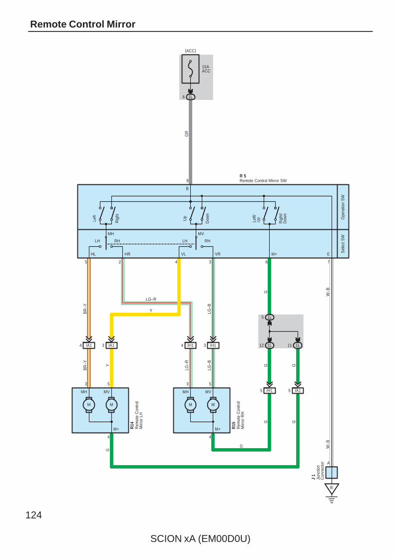
124
SCION xA (EM00D0U)
Remote Control Mirror
6 1L
15AACC
B
EM+VRVLHRHL
RHLHRHLH
Rig
ht/
Dow
n
Left/
Up
Dow
n
Up
Rig
ht
Sel
ect S
WO
pera
tion
SW
GR
R 5
J 1
8
7632 45
IE
IA14 3 IA1
M M
IH14 3 IH1
M M
1L5
1L12
IH15 IA15
1L11
4 4
3 5 3 5
LG–R
YBR
–Y
LG–B
BR
–Y Y
LG–R
LG–B G G
G
W–B
G G
W–B
G
G
R15
R14
A
MH MV MH MV
MH MV
M+ M+
Left
Junc
tion
Con
nect
or
Remote Control Mirror SW
Rem
ote
Con
trol
Mirr
or L
H
Rem
ote
Con
trol
Mirr
or R
H
(ACC)

SCION xA (EM00D0U)
125
: Parts Location
Code See Page Code See Page Code See Page
J1 31 R14 33
R5 31 R15 33
: Junction Block and Wire Harness Connector
Code See Page Junction Block and Wire Harness (Connector Location)
1L 25 Instrument Panel Wire and Instrument Panel J/B (Lower Finish Panel)
: Connector Joining Wire Harness and Wire Harness
Code See Page Joining Wire Harness and Wire Harness (Connector Location)
IA1 36 Front Door LH Wire and Instrument Panel Wire (Left Kick Panel)
IH1 37 Front Door RH Wire and Instrument Panel Wire (Right Kick Panel)
: Ground Points
Code See Page Ground Points Location
IE 36 Left Kick Panel
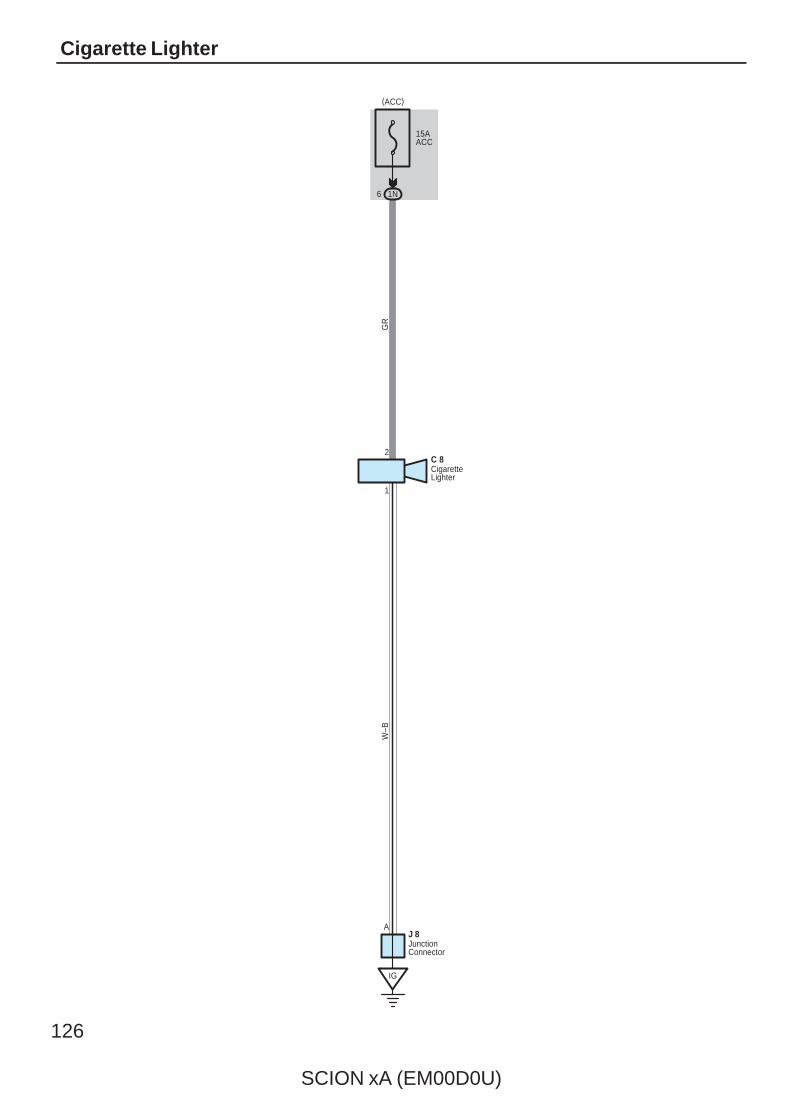
126
SCION xA (EM00D0U)
Cigarette Lighter
15AACC
1N6
1
2
J 8
GR
W–B
C 8
IG
A
CigaretteLighter
JunctionConnector
(ACC)
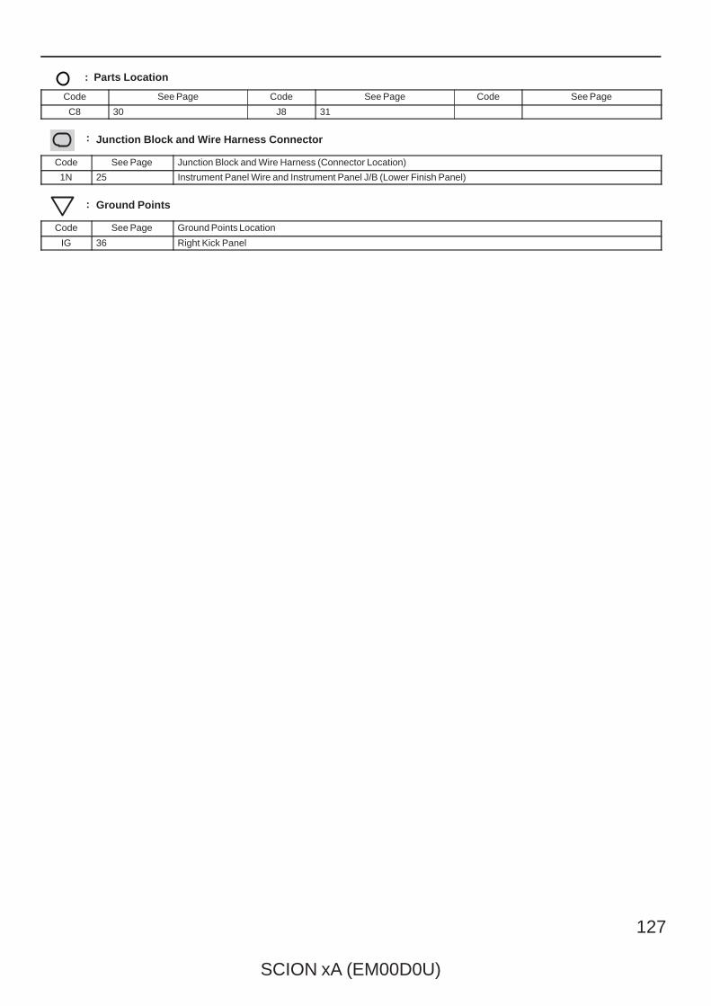
SCION xA (EM00D0U)
127
: Parts Location
Code See Page Code See Page Code See Page
C8 30 J8 31
: Junction Block and Wire Harness Connector
Code See Page Junction Block and Wire Harness (Connector Location)
1N 25 Instrument Panel Wire and Instrument Panel J/B (Lower Finish Panel)
: Ground Points
Code See Page Ground Points Location
IG 36 Right Kick Panel

128
SCION xA (EM00D0U)
Horn
15AHORN
2
2 3
1 5
2 2
2 2
ID34
1
G–W
W–R
G–R
G–R
2
S16H 5
HORNRelay
G–R
W–R
H 41
Hor
n
G–W
Spiral CableHorn(Low)
Horn(High)
(BAT)
6
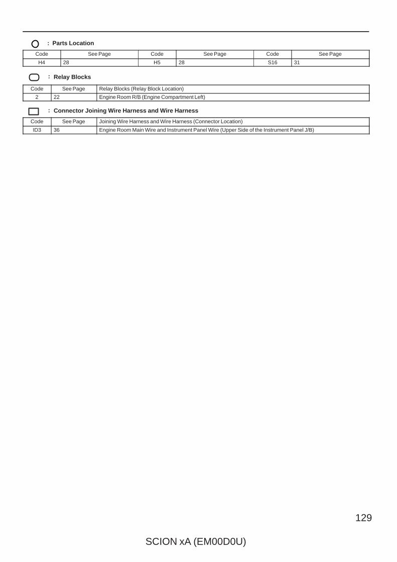
SCION xA (EM00D0U)
129
: Parts Location
Code See Page Code See Page Code See Page
H4 28 H5 28 S16 31
: Relay Blocks
Code See Page Relay Blocks (Relay Block Location)
2 22 Engine Room R/B (Engine Compartment Left)
: Connector Joining Wire Harness and Wire Harness
Code See Page Joining Wire Harness and Wire Harness (Connector Location)
ID3 36 Engine Room Main Wire and Instrument Panel Wire (Upper Side of the Instrument Panel J/B)
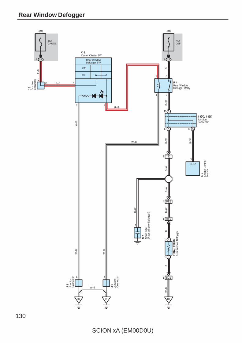
130
SCION xA (EM00D0U)
Rear Window Defogger
W–B
3 1J
25ADEF
10AGAUGE
1R8
A
IG
W–B
On
Off
1 3
2 5
BJ
3
W–B
4
Rear WindowDefogger SW
2
R 4C
C
A
J 2
R–B
R–B
B
IE
W–BJ 8
J 1
BG11
BF11
BE24
7 IB2
1
R–B
W–B B–W
B–W
B–W
B–W
BB
W–B
N 2
R11
( A) ,
R12
( B)
Junc
tion
Con
nect
or
Junc
tion
Con
nect
or
Junc
tion
Con
nect
or
Noi
se F
ilter
( Rea
r W
indo
w D
efog
ger)
Rear WindowDefogger Relay
Rea
r W
indo
w D
efog
ger
Center Cluster SWC 6
A1
B1
(IG)(IG)
B–W
B–W
ELS2
3
Eng
ine
Con
trol
Mod
ule
E 5
B–W
AE AE
BE
JunctionConnector
J 4(A), J 5(B)
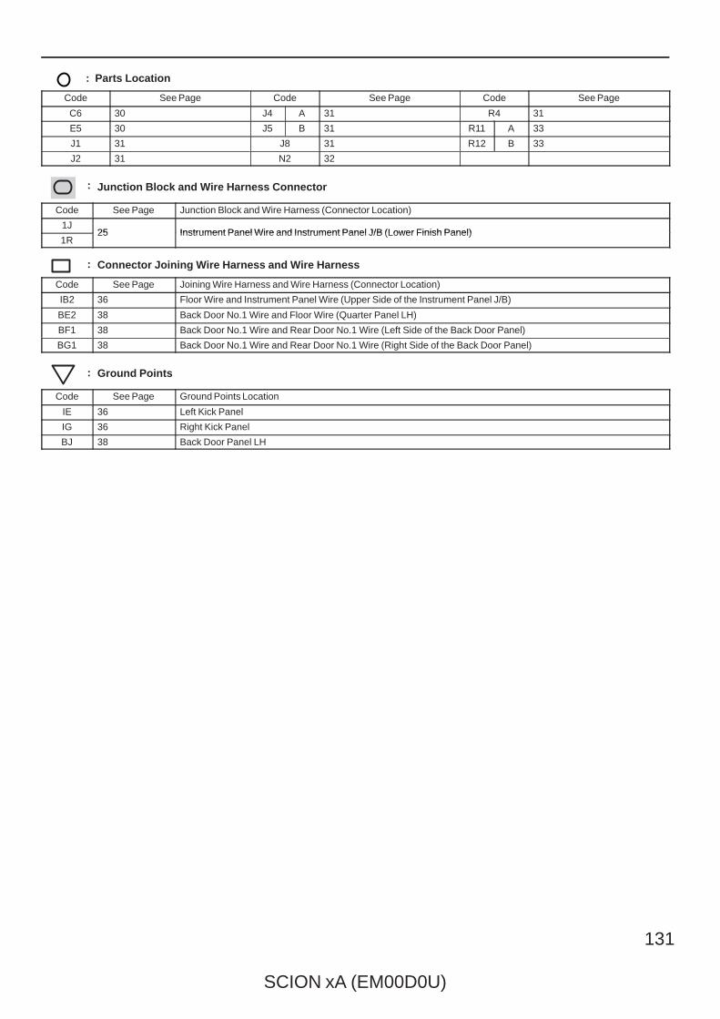
SCION xA (EM00D0U)
131
: Parts Location
Code See Page Code See Page Code See Page
C6 30 J4 A 31 R4 31
E5 30 J5 B 31 R11 A 33
J1 31 J8 31 R12 B 33
J2 31 N2 32
: Junction Block and Wire Harness Connector
Code See Page Junction Block and Wire Harness (Connector Location)
1J25 Instrument Panel Wire and Instrument Panel J/B (Lower Finish Panel)
1R25 Instrument Panel Wire and Instrument Panel J/B (Lower Finish Panel)
: Connector Joining Wire Harness and Wire Harness
Code See Page Joining Wire Harness and Wire Harness (Connector Location)
IB2 36 Floor Wire and Instrument Panel Wire (Upper Side of the Instrument Panel J/B)
BE2 38 Back Door No.1 Wire and Floor Wire (Quarter Panel LH)
BF1 38 Back Door No.1 Wire and Rear Door No.1 Wire (Left Side of the Back Door Panel)
BG1 38 Back Door No.1 Wire and Rear Door No.1 Wire (Right Side of the Back Door Panel)
: Ground Points
Code See Page Ground Points Location
IE 36 Left Kick Panel
IG 36 Right Kick Panel
BJ 38 Back Door Panel LH
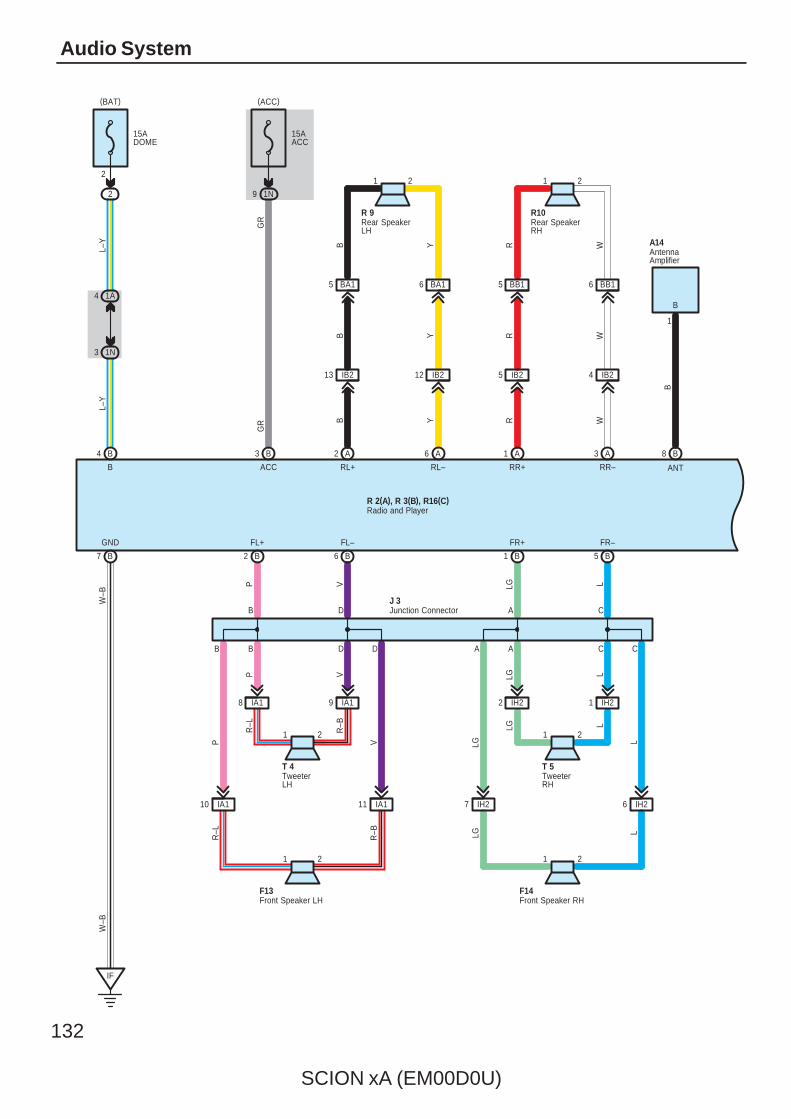
132
SCION xA (EM00D0U)
Audio System
15ADOME
2
15AACC
1N9
1A4
1N3
L
9
B4 B3
L–Y
L–Y
GR
GR
B7
IF
1 2
1
B1 B5
GND FR+ FR–
LG L
B
F14
B
B
1 2
B2 B6
FL+ FL–
P V
F13
6 BB1
Y
1 221 R–B
IH22
W–B
W–B
B ACC
2
IA18
T 4
R–L
IA1
RR–RR+RL–RL+
A2 A6 A1 A3
IB213 IB212 IB25 IB24
1 2 1 2
WWRYB
W
5 BB1
R
R 9
YB
R10
LGR
T 5
A14
1 IH2
6 BA15 BA1
B
ANT
AntennaAmplifier
Front Speaker LH Front Speaker RH
Rear SpeakerLH
Rear SpeakerRH
TweeterLH
TweeterRH
8
(ACC)(BAT)
Radio and PlayerR 2(A), R 3(B), R16(C)
IH26IH27
LLGLG L
B D A C
P V LG L
B D A C
IA111IA110
VPR
–L
R–B
Junction ConnectorJ 3
B D A C
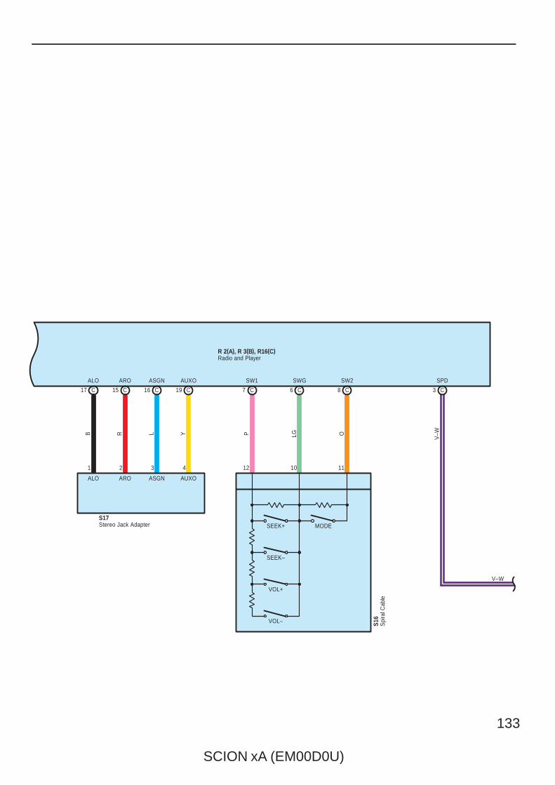
SCION xA (EM00D0U)
133
C17 15 C 16 C 19 C 7 C 6 C 8 C 3 C
ALO ARO ASGN AUXO SW1 SWG SW2 SPD
Radio and PlayerR 2(A), R 3(B), R16(C)
Stereo Jack AdapterS17
ALO
1
B R
2
ARO ASGN
3
L Y
4
AUXO
P LG O
V–W
S16
SEEK+
SEEK–
VOL+
VOL–
MODE
Spi
ral C
able
12 10 11
V–W
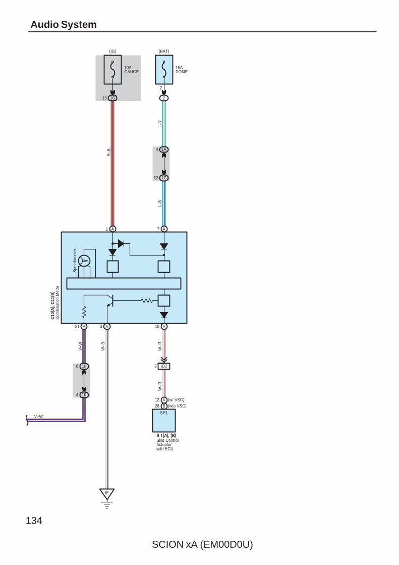
134
SCION xA (EM00D0U)
Audio System
10AGAUGE
(IG)
15ADOME
2
2
(BAT)
1A4
1G12
A1 A7
R–B
A10A3
Spe
edom
eter
A21
IF
ID23
SP1
(w/o VSC)B26(w/ VSC)A12
Skid ControlActuatorwith ECU
S 1(A), (B)
W–R
W–R
W–B
Com
bina
tion
Met
erC
10( A
) , C
11( B
)
1F6
1K4
V–W
V–W
1G13
L–Y
L–B
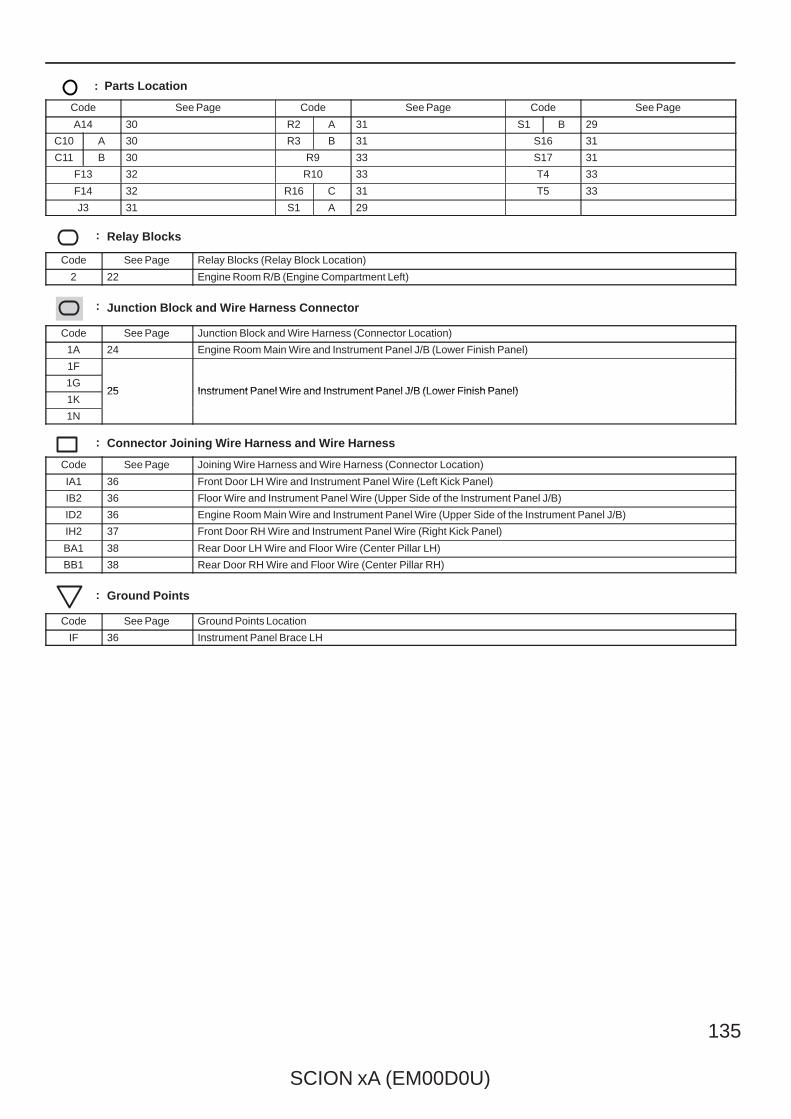
SCION xA (EM00D0U)
135
: Parts Location
Code See Page Code See Page Code See Page
A14 30 R2 A 31 S1 B 29
C10 A 30 R3 B 31 S16 31
C11 B 30 R9 33 S17 31
F13 32 R10 33 T4 33
F14 32 R16 C 31 T5 33
J3 31 S1 A 29
: Relay Blocks
Code See Page Relay Blocks (Relay Block Location)
2 22 Engine Room R/B (Engine Compartment Left)
: Junction Block and Wire Harness Connector
Code See Page Junction Block and Wire Harness (Connector Location)
1A 24 Engine Room Main Wire and Instrument Panel J/B (Lower Finish Panel)
1F
25 Instrument Panel Wire and Instrument Panel J/B (Lower Finish Panel)1G
25 Instrument Panel Wire and Instrument Panel J/B (Lower Finish Panel)1K
25 Instrument Panel Wire and Instrument Panel J/B (Lower Finish Panel)
1N
: Connector Joining Wire Harness and Wire Harness
Code See Page Joining Wire Harness and Wire Harness (Connector Location)
IA1 36 Front Door LH Wire and Instrument Panel Wire (Left Kick Panel)
IB2 36 Floor Wire and Instrument Panel Wire (Upper Side of the Instrument Panel J/B)
ID2 36 Engine Room Main Wire and Instrument Panel Wire (Upper Side of the Instrument Panel J/B)
IH2 37 Front Door RH Wire and Instrument Panel Wire (Right Kick Panel)
BA1 38 Rear Door LH Wire and Floor Wire (Center Pillar LH)
BB1 38 Rear Door RH Wire and Floor Wire (Center Pillar RH)
: Ground Points
Code See Page Ground Points Location
IF 36 Instrument Panel Brace LH
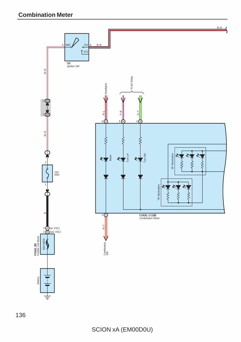
136
SCION xA (EM00D0U)
Combination Meter
Bea
m
Turn
LH
Turn
RH
SP
Illu
min
atio
n
TM Il
lum
inat
ion
60A
MA
IN
F10(
A), (
B)B
atte
ry
2
15AAM2
1
2
2
1A7
1O1
5 6AM2 IG2
ST2
BW
–RW
–R
I10
B–R
B–R
A8 A5 A4
A2
R–L
P–B
G–Y
Hea
dlig
hts
FLS
H R
elay
C10(A), C11(B)
Com
bina
tion
SW
R–Y
Combination Meter
Fusi
ble
Link
Blo
ck
Ignition SW
(w/o VSC)B2(w/ VSC)A3
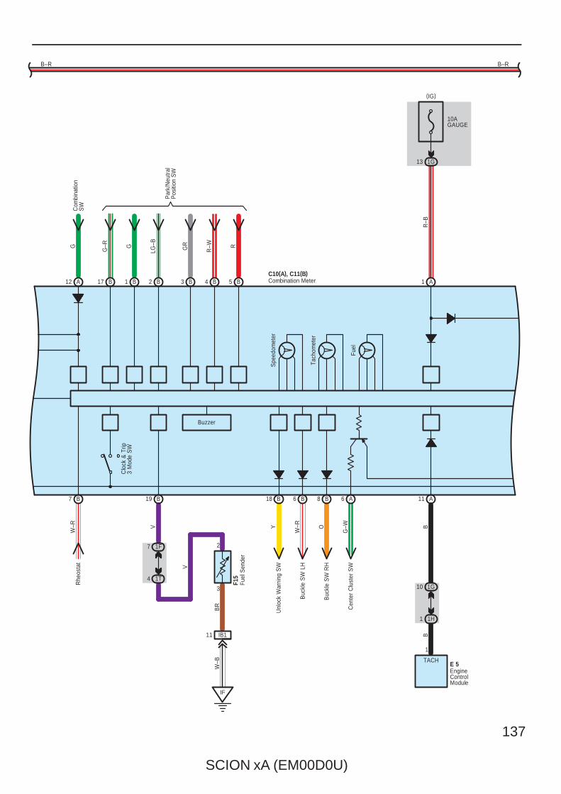
SCION xA (EM00D0U)
137
Spe
edom
eter
Tach
omet
er
Fuel
Clo
ck &
Trip
3 M
ode
SW
Buzzer
B–R
A12 B17 B1 B2 B3 B4 B5 A1
A11A6B8B6B18B19B7
G
G–R G
LG–B
GR
R–W R
Com
bina
tion
SW
Par
k/N
eutra
lP
ositi
on S
W
C10(A), C11(B)
Rhe
osta
tW
–R
1F7
1T4
IF
IB111
3
2
V
V
BR
W–B
F15
Unl
ock
War
ning
SW
Y
Buc
kle
SW
LH
W–R
Buc
kle
SW
RH
O
Cen
ter
Clu
ster
SW
G–W
1G10
1H1
TACH
1
B
E 5
B–R
10AGAUGE
1G13
R–B
Combination Meter
EngineControlModule
Fuel
Sen
der
(IG)
B
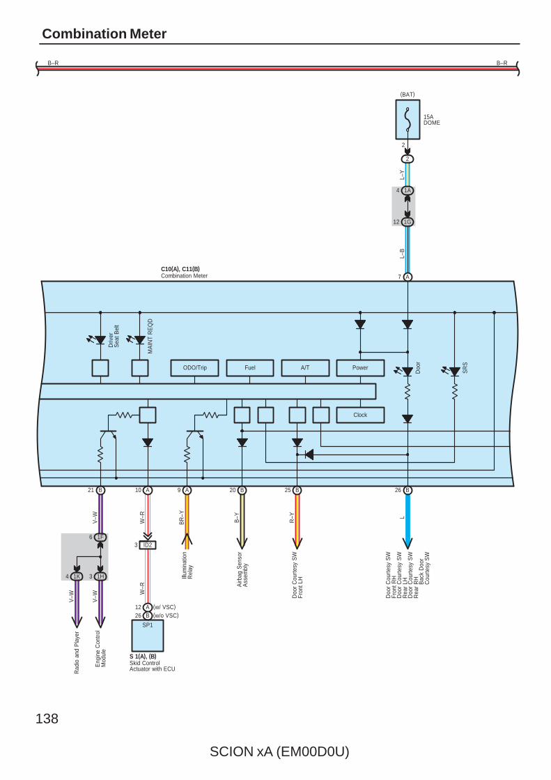
138
SCION xA (EM00D0U)
Combination Meter
ODO/Trip Fuel A/T
Clock
Power
Driv
erS
eat B
elt
MA
INT
RE
QD
Doo
r
SR
S
B21 A10 A9 B20 B25 B26
A7
Airb
ag S
enso
rA
ssem
bly
B–Y
Doo
r C
ourte
sy S
WFr
ont L
HR
–Y
Doo
r C
ourte
sy S
WFr
ont R
HL
Illum
inat
ion
Rel
ayB
R–Y
Doo
r C
ourte
sy S
WR
ear
LHD
oor
Cou
rtesy
SW
Rea
r R
HB
ack
Doo
rC
ourte
sy S
W
1F6
1H3
Eng
ine
Con
trol
Mod
ule
V–W
V–W
ID23
SP1
S 1(A), (B)
W–R
W–R
1A4
12 1G
15ADOME
2
2
B–R B–R
L–Y
C10(A), C11(B)
Skid ControlActuator with ECU
Combination Meter
L–B
(BAT)
(w/o VSC)B26(w/ VSC)A12
Rad
io a
nd P
laye
r
1K4
V–W
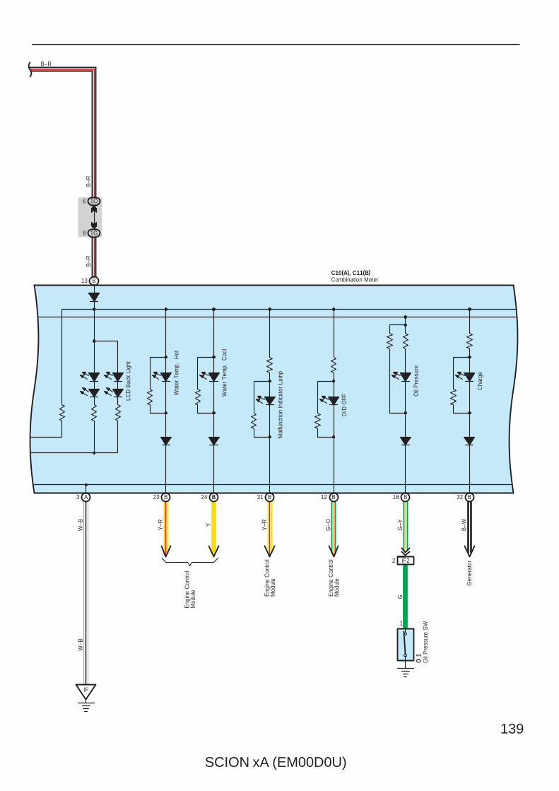
SCION xA (EM00D0U)
139
LCD
Bac
k Li
ght
Wat
er T
emp.
H
ot
Wat
er T
emp.
C
ool
Mal
func
tion
Indi
cato
r La
mp
O/D
OFF
Oil
Pre
ssur
e
Cha
rge
B13
A3 B31 B12 B16 32 B
1O6
1G8
B–R
B–R
B–R
IF
Eng
ine
Con
trol
Mod
ule
Y–R
Eng
ine
Con
trol
Mod
ule
G–O
Gen
erat
orB
–W
W–B
W–B
IF22
1
G–Y
G
O 1
C10(A), C11(B)Combination Meter
Oil
Pre
ssur
e S
W
B24 B
Y
23 B
Y–R
Eng
ine
Con
trol
Mod
ule

140
SCION xA (EM00D0U)
Combination Meter
BR
AK
E
AB
S
TRA
C O
FF
Slip
VS
C
B15 B14 B11 B30 B27 B10
C10(A), C11(B)
ID32
B–Y P R–L
B–R
BR
–W
ED
2
1
Y–R
Y–R
W–B
B 2
Skid Control Actuatorwith ECU
Bra
ke F
luid
Lev
elW
arni
ng S
W
Combination Meter
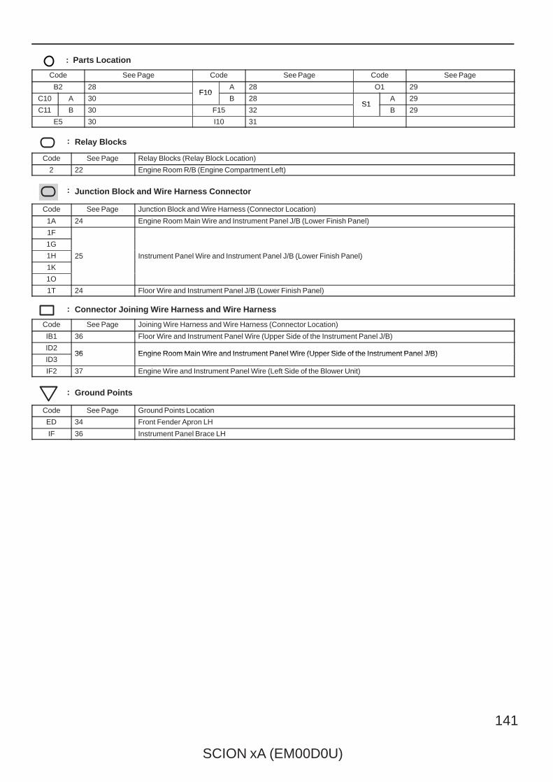
SCION xA (EM00D0U)
141
: Parts Location
Code See Page Code See Page Code See Page
B2 28F10
A 28 O1 29
C10 A 30F10
B 28S1
A 29
C11 B 30 F15 32S1
B 29
E5 30 I10 31
: Relay Blocks
Code See Page Relay Blocks (Relay Block Location)
2 22 Engine Room R/B (Engine Compartment Left)
: Junction Block and Wire Harness Connector
Code See Page Junction Block and Wire Harness (Connector Location)
1A 24 Engine Room Main Wire and Instrument Panel J/B (Lower Finish Panel)
1F
25 Instrument Panel Wire and Instrument Panel J/B (Lower Finish Panel)
1G
25 Instrument Panel Wire and Instrument Panel J/B (Lower Finish Panel)1H 25 Instrument Panel Wire and Instrument Panel J/B (Lower Finish Panel)
1K
25 Instrument Panel Wire and Instrument Panel J/B (Lower Finish Panel)
1O
1T 24 Floor Wire and Instrument Panel J/B (Lower Finish Panel)
: Connector Joining Wire Harness and Wire Harness
Code See Page Joining Wire Harness and Wire Harness (Connector Location)
IB1 36 Floor Wire and Instrument Panel Wire (Upper Side of the Instrument Panel J/B)
ID236 Engine Room Main Wire and Instrument Panel Wire (Upper Side of the Instrument Panel J/B)
ID336 Engine Room Main Wire and Instrument Panel Wire (Upper Side of the Instrument Panel J/B)
IF2 37 Engine Wire and Instrument Panel Wire (Left Side of the Blower Unit)
: Ground Points
Code See Page Ground Points Location
ED 34 Front Fender Apron LH
IF 36 Instrument Panel Brace LH
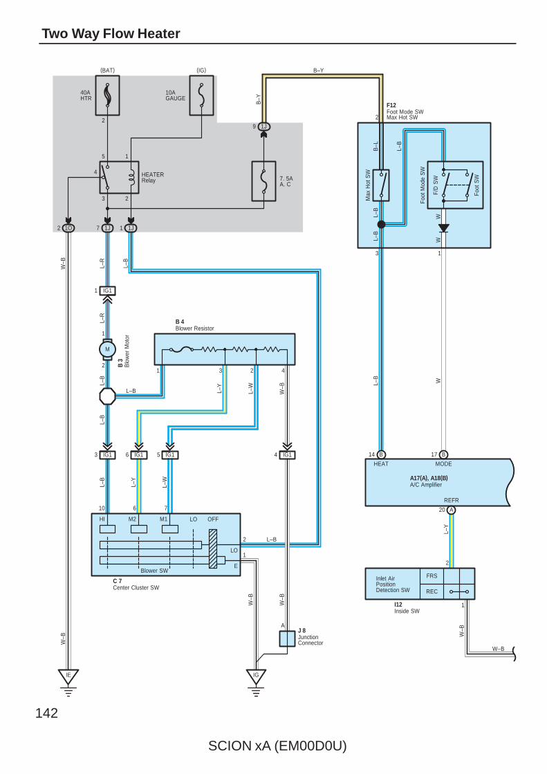
142
SCION xA (EM00D0U)
Two Way Flow Heater
7. 5AA. C
40AHTR
10AGAUGE
3 2
4
5 1
1J7 1J11O2
1J9
IE
W–B
W–B
IG
W–B
L–R
L–B
L–B
HEATERRelay
B–Y
B–Y
2
13
Foot
SW
A17(A), A18(B)
F/D
SW
W–B
F12
Max
Hot
SW
2
WL–
Y
HEAT MODE
REFR
Inlet AirPositionDetection SW
W–B
L–W
L–Y
L–W
L–B W–B
L–R
L–Y
L–B
L–B
J 8A
B–L
L–B
WL–B
L–B
Foot
Mod
e S
W
FRS
REC
2
1
10 6 7
2
1
HI M2 M1 LO OFF
C 7
L–B
Blower SW
Center Cluster SW
JunctionConnector
Foot Mode SWMax Hot SW
A/C Amplifier
I12Inside SW
IG11
2
1
1 3 2 4
IG13 IG16 IG15 IG14
Blower ResistorB 4
Blo
wer
Mot
orB
3
(IG)(BAT)
B14 B17
A20
W–B
L–B
M
LO
E
W

SCION xA (EM00D0U)
143
7. 5AECU–IG
1H11
E
E
A
IG
J 8
A
32 81
7
A 8J 7
L
W–BW–B
L–O
L–RG
W–B
W–B
LL
L
A
IG+ RECFRSR/F
GND
E
A
M ControlCircuit
B
Air Inlet ControlServo Motor
JunctionConnector
Junc
tion
Con
nect
or(IG)
A14 A18 A16 A28
A24
A17(A), A18(B)A/C Amplifier
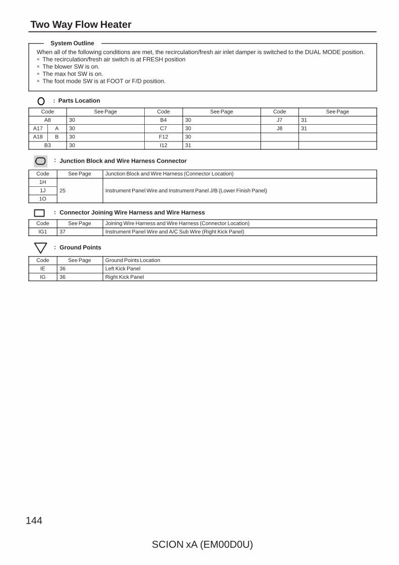
144
SCION xA (EM00D0U)
Two Way Flow Heater
When all of the following conditions are met, the recirculation/fresh air inlet damper is switched to the DUAL MODE position.∗ The recirculation/fresh air switch is at FRESH position∗ The blower SW is on.∗ The max hot SW is on.∗ The foot mode SW is at FOOT or F/D position.
: Parts Location
Code See Page Code See Page Code See Page
A8 30 B4 30 J7 31
A17 A 30 C7 30 J8 31
A18 B 30 F12 30
B3 30 I12 31
: Junction Block and Wire Harness Connector
Code See Page Junction Block and Wire Harness (Connector Location)
1H
25 Instrument Panel Wire and Instrument Panel J/B (Lower Finish Panel)1J 25 Instrument Panel Wire and Instrument Panel J/B (Lower Finish Panel)
1O
25 Instrument Panel Wire and Instrument Panel J/B (Lower Finish Panel)
: Connector Joining Wire Harness and Wire Harness
Code See Page Joining Wire Harness and Wire Harness (Connector Location)
IG1 37 Instrument Panel Wire and A/C Sub Wire (Right Kick Panel)
: Ground Points
Code See Page Ground Points Location
IE 36 Left Kick Panel
IG 36 Right Kick Panel
System Outline

SCION xA (EM00D0U)
145
Memo
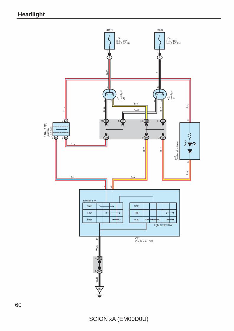
60
SCION xA (EM00D0U)
Headlight
2 1O
1M6
Head
Tail
OFFFlash
Low
High
W–B
IE
B BB B 2 1F5 1M7 1M
11 1B10 1B8 1A9 1A
3
21
3
21
2
10AH–LP RH/H–LP LO RH
10AH–LP LH/H–LP LO LH
2
R–Y
H 2
H 1
B–Y
B–WB
–R B
B–W B–Y
C10
R–L
R–L
R–Y
R–Y
R–Y
8 9
Dimmer SW
J 4(
A), J
5( B
)
Light Control SW
C12
W–B
11
2 2
AB
R–L
2
R–L
Bea
m
8
Com
bina
tion
Met
er
Combination SW
Hea
dlig
htLH H
eadl
ight
RH
Junc
tion
Con
nect
or
(BAT)(BAT)
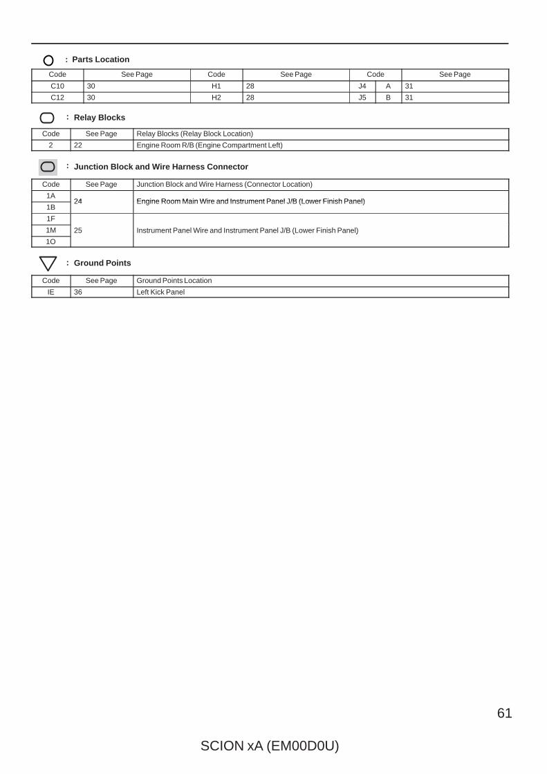
SCION xA (EM00D0U)
61
: Parts Location
Code See Page Code See Page Code See Page
C10 30 H1 28 J4 A 31
C12 30 H2 28 J5 B 31
: Relay Blocks
Code See Page Relay Blocks (Relay Block Location)
2 22 Engine Room R/B (Engine Compartment Left)
: Junction Block and Wire Harness Connector
Code See Page Junction Block and Wire Harness (Connector Location)
1A24 Engine Room Main Wire and Instrument Panel J/B (Lower Finish Panel)
1B24 Engine Room Main Wire and Instrument Panel J/B (Lower Finish Panel)
1F
25 Instrument Panel Wire and Instrument Panel J/B (Lower Finish Panel)1M 25 Instrument Panel Wire and Instrument Panel J/B (Lower Finish Panel)
1O
25 Instrument Panel Wire and Instrument Panel J/B (Lower Finish Panel)
: Ground Points
Code See Page Ground Points Location
IE 36 Left Kick Panel
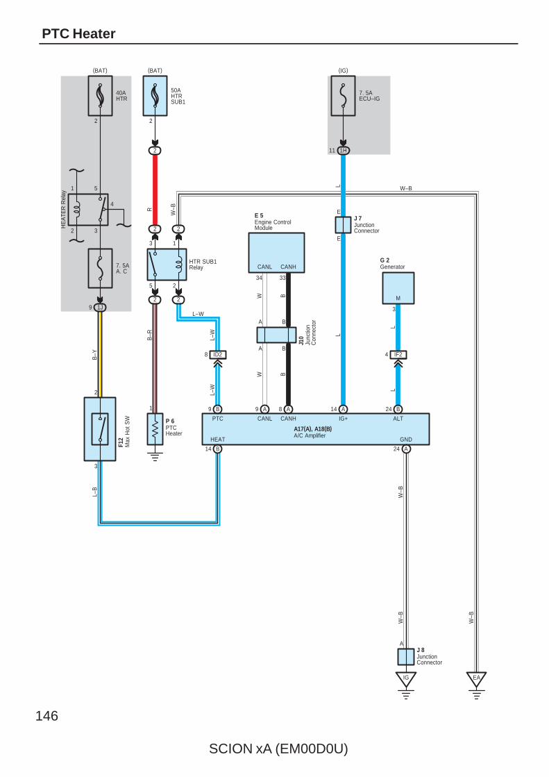
146
SCION xA (EM00D0U)
PTC Heater
50AHTRSUB1
2
7. 5AECU–IG
5 2
3 1
2 2
HTR SUB1Relay
2 2
J 7E
E
ID28
L–W
PTC ALT
B–R
R
L–W L
2
HEAT
L–W
IG+
A17(A), A18(B)
IG
GND
W–B
A
W–B
4 IF2
G 2
3
L
1
P 6
1H11
L
2
F12
3
L
M
J 8
Generator
JunctionConnector
JunctionConnector
Max
Hot
SW
A/C AmplifierPTCHeater
(IG)(BAT)
L–B
7. 5AA. C
1J9
B–Y
2 3
1 5
40AHTR
2
(BAT)H
EA
TER
Rel
ay
4
B24A14B9
A24B14
CANHCANL
Engine ControlModule
E 5
A9 A8
CANL CANH
A B
34 33
BA
BWW B
Junc
tion
Con
nect
or
J10
EA
W–B
W–B
W–B
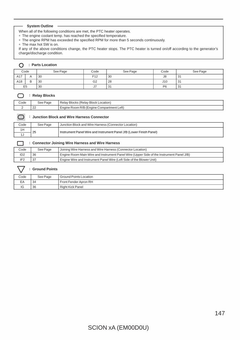
SCION xA (EM00D0U)
147
When all of the following conditions are met, the PTC heater operates.∗ The engine coolant temp. has reached the specified temperature.∗ The engine RPM has exceeded the specified RPM for more than 5 seconds continuously.∗ The max hot SW is on.If any of the above conditions change, the PTC heater stops. The PTC heater is turned on/off according to the generator’scharge/discharge condition.
: Parts Location
Code See Page Code See Page Code See Page
A17 A 30 F12 30 J8 31
A18 B 30 G2 28 J10 31
E5 30 J7 31 P6 31
: Relay Blocks
Code See Page Relay Blocks (Relay Block Location)
2 22 Engine Room R/B (Engine Compartment Left)
: Junction Block and Wire Harness Connector
Code See Page Junction Block and Wire Harness (Connector Location)
1H25 Instrument Panel Wire and Instrument Panel J/B (Lower Finish Panel)
1J25 Instrument Panel Wire and Instrument Panel J/B (Lower Finish Panel)
: Connector Joining Wire Harness and Wire Harness
Code See Page Joining Wire Harness and Wire Harness (Connector Location)
ID2 36 Engine Room Main Wire and Instrument Panel Wire (Upper Side of the Instrument Panel J/B)
IF2 37 Engine Wire and Instrument Panel Wire (Left Side of the Blower Unit)
: Ground Points
Code See Page Ground Points Location
EA 34 Front Fender Apron RH
IG 36 Right Kick Panel
System Outline
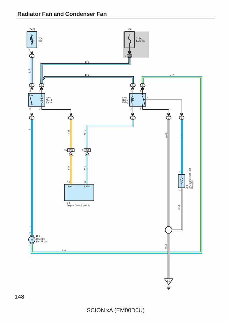
148
SCION xA (EM00D0U)
Radiator Fan and Condenser Fan
30ARDI
2
7. 5AECU–IG
1B3
5 2
3 1
2 2
2 2
2 2
2 2
1 3
2 5
4
1
2
2
15 ID3 11 ID3
FANNO. 1Relay
FANNO. 2Relay
L–R
B–L
Y–R
LW
–B
A 1
LL
R 1
W–B
2
1
2
L–Y
L–Y
B–L
13 14
ED
W–B
W–L
Y–R
FANL FANH
E 6
A/C
Con
dens
er F
anR
esis
tor
Engine Control Module
RadiatorFan Motor
(IG)(BAT)
W–L
M

SCION xA (EM00D0U)
149
The current is applied at all times through the RDI fuse to TERMINAL 3 of the FAN NO.1 relay.When the ignition SW is turned on, the current flows through the ECU–IG fuse to FAN NO.1 relay (Coil side) to TERMINAL 6of the engine control module. At the same time as this current flow, the current from ECU–IG fuse flows to the FAN NO.2relay (Coil side) to TERMINAL 7 of the engine control module.
1. Low Speed OperationWhen the A/C system is operating, the FAN NO.1 Relay is turned on. As a result, the current flows from the RDI fuse to FANNO.1 relay (Point side) to TERMINAL 2 of the radiator fan motor to TERMINAL 1 to TERMINAL 3 of the FAN NO.2 relay toTERMINAL 4 to TERMINAL 2 of the A/C condenser fan resistor to TERMINAL 1 to GROUND, and the radiator fan motorrotates at low speed.
2. High Speed OperationWhen the engine control module operated, the FAN NO.1 and NO.2 relay is turned on. As a result, the current flows from theRDI fuse to FAN NO.1 relay (Point side) to radiator fan motor to TERMINAL 3 of the FAN NO.2 Relay to TERMINAL 5 toGROUND, and the radiator fan motor rotates at high speed.
: Parts Location
Code See Page Code See Page Code See Page
A1 28 E6 30 R1 29
: Relay Blocks
Code See Page Relay Blocks (Relay Block Location)
2 22 Engine Room R/B (Engine Compartment Left)
: Junction Block and Wire Harness Connector
Code See Page Junction Block and Wire Harness (Connector Location)
1B 24 Engine Room Main Wire and Instrument Panel J/B (Lower Finish Panel)
: Connector Joining Wire Harness and Wire Harness
Code See Page Joining Wire Harness and Wire Harness (Connector Location)
ID3 36 Engine Room Main Wire and Instrument Panel Wire (Upper Side of the Instrument Panel J/B)
: Ground Points
Code See Page Ground Points Location
ED 34 Front Fender Apron LH
System Outline
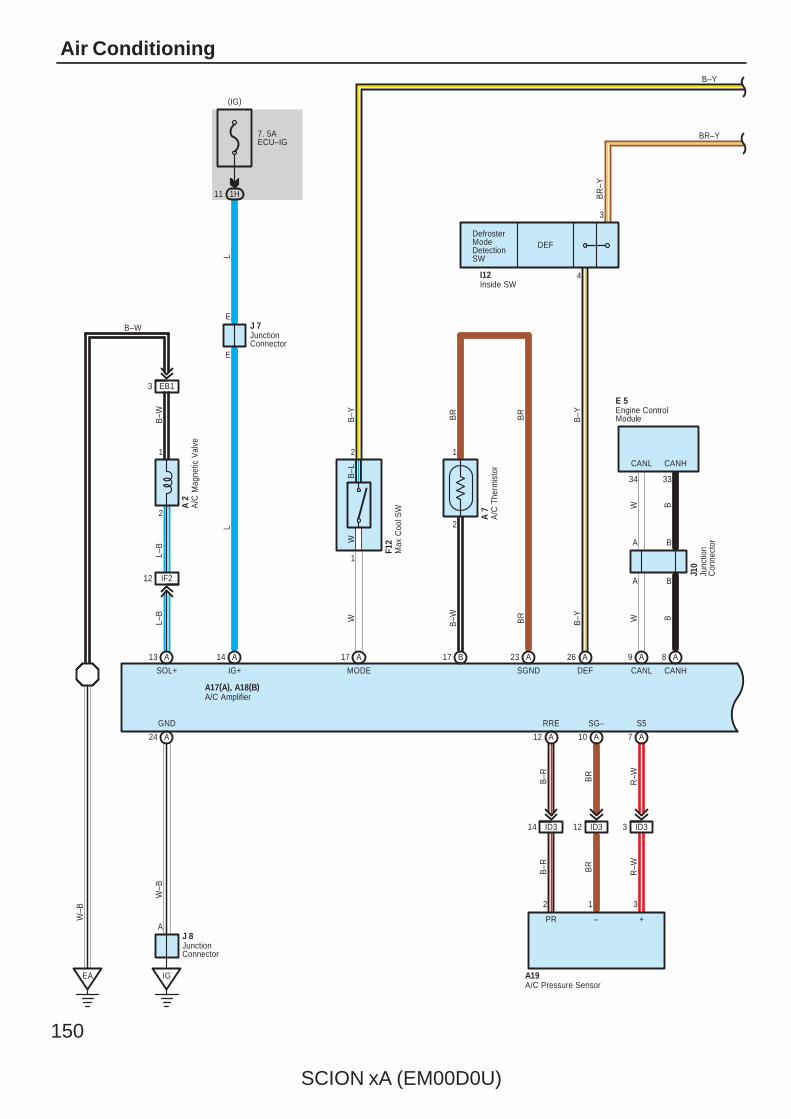
150
SCION xA (EM00D0U)
Air Conditioning
DEF
EB13
2
1
IF212
DefrosterModeDetectionSW
L–B
B–W BR
B–Y
B–W BR
BR
–Y
B–YBR
B–W
BR–Y
L–B
SOL+ MODE SGND DEF
A 2
A 7
4
3
I12
A17(A), A18(B)
A/C
Mag
netic
Val
ve
A/C
The
rmis
tor
A/C Amplifier
Inside SW
EA
W–B
CANHCANL
3334
A B
A B
W BBW
Junc
tion
Con
nect
or
J10
Engine ControlModule
E 5
CANL CANH
A/C Pressure SensorA19
ID314 ID312 ID33
2 1 3
S5SG–RRE
PR – +
B–R BR
R–W
B–R BR
R–W
7. 5AECU–IG
1H11
(IG)
JunctionConnector
J 7E
LL
E
IG+
IG
A
W–B
J 8JunctionConnector
GND
2
1
F12
Max
Coo
l SW
B–L
W
2
1
W
A13 A14 A17 B17 A23 A26 A9 A8
A24 A12 A10 A7
B–Y
B–Y
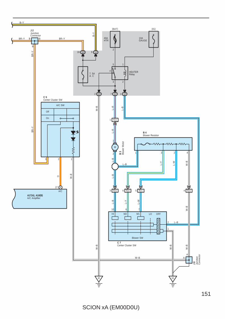
SCION xA (EM00D0U)
151
7. 5AA. C
40AHTR
10AGAUGE
3 2
4
5 1
1J7 1J11O2
1H18
10 6 7
2
1
HI M2 M1 LO OFF
W–B
W–B
A
W–B L–
R
L–B
L–B
HEATERRelay
On
2
Off
W–B
C 7
L–B
L–Y
1
L–W
W–B
IG
L–W
L–B W–B
L–R
L–Y
L–B
L–B
A
J 8
O
W–B
BR
–Y
W–B
A/C
B
BB
J 2
3 2 1
A/C SW
C 5Center Cluster SW
Center Cluster SW
Junc
tion
Con
nect
or
JunctionConnector
3 IG1 IG16 IG15 IG14
IG11
3 2 42
1
Blower ResistorB 4
Blo
wer
Mot
orB
3
Blower SW
(IG)(BAT)
BR–YBR–Y
M
BR
–Y
A17(A), A18(B)A/C Amplifier
IE
A27
1J9
B–Y
B–Y
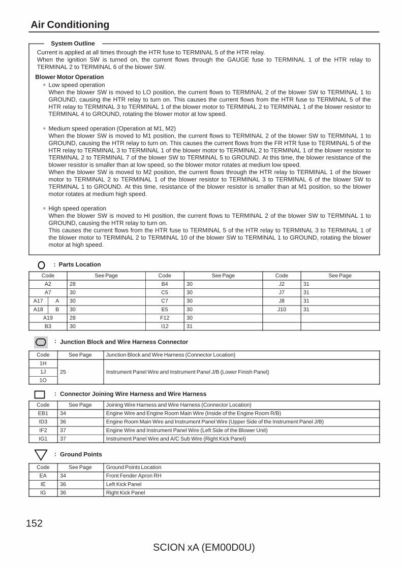
152
SCION xA (EM00D0U)
Air Conditioning
Current is applied at all times through the HTR fuse to TERMINAL 5 of the HTR relay.When the ignition SW is turned on, the current flows through the GAUGE fuse to TERMINAL 1 of the HTR relay toTERMINAL 2 to TERMINAL 6 of the blower SW.
Blower Motor Operation∗ Low speed operation
When the blower SW is moved to LO position, the current flows to TERMINAL 2 of the blower SW to TERMINAL 1 toGROUND, causing the HTR relay to turn on. This causes the current flows from the HTR fuse to TERMINAL 5 of theHTR relay to TERMINAL 3 to TERMINAL 1 of the blower motor to TERMINAL 2 to TERMINAL 1 of the blower resistor toTERMINAL 4 to GROUND, rotating the blower motor at low speed.
∗ Medium speed operation (Operation at M1, M2)When the blower SW is moved to M1 position, the current flows to TERMINAL 2 of the blower SW to TERMINAL 1 toGROUND, causing the HTR relay to turn on. This causes the current flows from the FR HTR fuse to TERMINAL 5 of theHTR relay to TERMINAL 3 to TERMINAL 1 of the blower motor to TERMINAL 2 to TERMINAL 1 of the blower resistor toTERMINAL 2 to TERMINAL 7 of the blower SW to TERMINAL 5 to GROUND. At this time, the blower resistance of theblower resistor is smaller than at low speed, so the blower motor rotates at medium low speed.When the blower SW is moved to M2 position, the current flows through the HTR relay to TERMINAL 1 of the blowermotor to TERMINAL 2 to TERMINAL 1 of the blower resistor to TERMINAL 3 to TERMINAL 6 of the blower SW toTERMINAL 1 to GROUND. At this time, resistance of the blower resistor is smaller than at M1 position, so the blowermotor rotates at medium high speed.
∗ High speed operationWhen the blower SW is moved to HI position, the current flows to TERMINAL 2 of the blower SW to TERMINAL 1 toGROUND, causing the HTR relay to turn on.This causes the current flows from the HTR fuse to TERMINAL 5 of the HTR relay to TERMINAL 3 to TERMINAL 1 ofthe blower motor to TERMINAL 2 to TERMINAL 10 of the blower SW to TERMINAL 1 to GROUND, rotating the blowermotor at high speed.
: Parts Location
Code See Page Code See Page Code See Page
A2 28 B4 30 J2 31
A7 30 C5 30 J7 31
A17 A 30 C7 30 J8 31
A18 B 30 E5 30 J10 31
A19 28 F12 30
B3 30 I12 31
: Junction Block and Wire Harness Connector
Code See Page Junction Block and Wire Harness (Connector Location)
1H
25 Instrument Panel Wire and Instrument Panel J/B (Lower Finish Panel)1J 25 Instrument Panel Wire and Instrument Panel J/B (Lower Finish Panel)
1O
25 Instrument Panel Wire and Instrument Panel J/B (Lower Finish Panel)
: Connector Joining Wire Harness and Wire Harness
Code See Page Joining Wire Harness and Wire Harness (Connector Location)
EB1 34 Engine Wire and Engine Room Main Wire (Inside of the Engine Room R/B)
ID3 36 Engine Room Main Wire and Instrument Panel Wire (Upper Side of the Instrument Panel J/B)
IF2 37 Engine Wire and Instrument Panel Wire (Left Side of the Blower Unit)
IG1 37 Instrument Panel Wire and A/C Sub Wire (Right Kick Panel)
: Ground Points
Code See Page Ground Points Location
EA 34 Front Fender Apron RH
IE 36 Left Kick Panel
IG 36 Right Kick Panel
System Outline

SCION xA (EM00D0U)
153
Memo
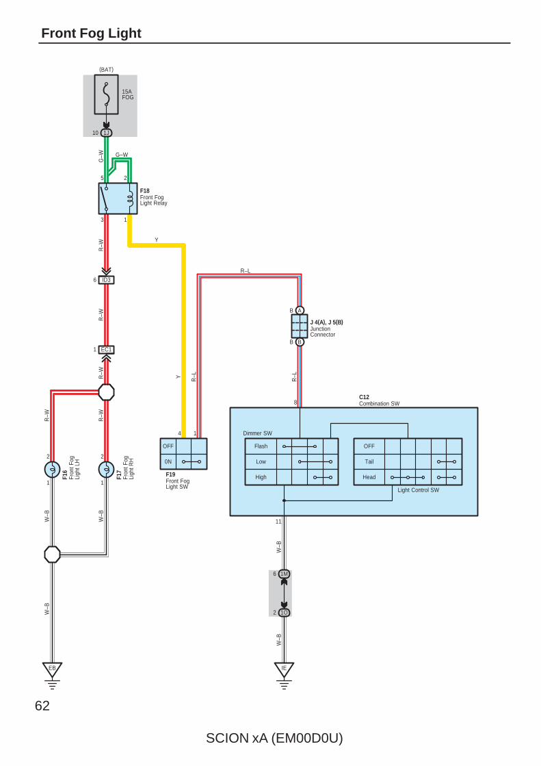
62
SCION xA (EM00D0U)
Front Fog Light
15AFOG
1J10
3 1
25
Front FogLight Relay
F18
G–W
ID36
R–W
EC11
R–W
R–W
1
2
1
2
EB
W–B
W–B
R–W
R–W
W–B
Fron
t Fog
Ligh
t RH
F17
Fron
t Fog
Ligh
t LH
F16
OFF
0N
4 1
Front FogLight SW
F19
AB
BB
JunctionConnector
J 4(A), J 5(B)
Y
Y R–L
R–L
R–L
Head
Tail
OFF
High
Low
Flash
Light Control SW
Dimmer SW
IE
11
1M6
1O2
W–B
W–B
8
G–W
Combination SWC12
(BAT)
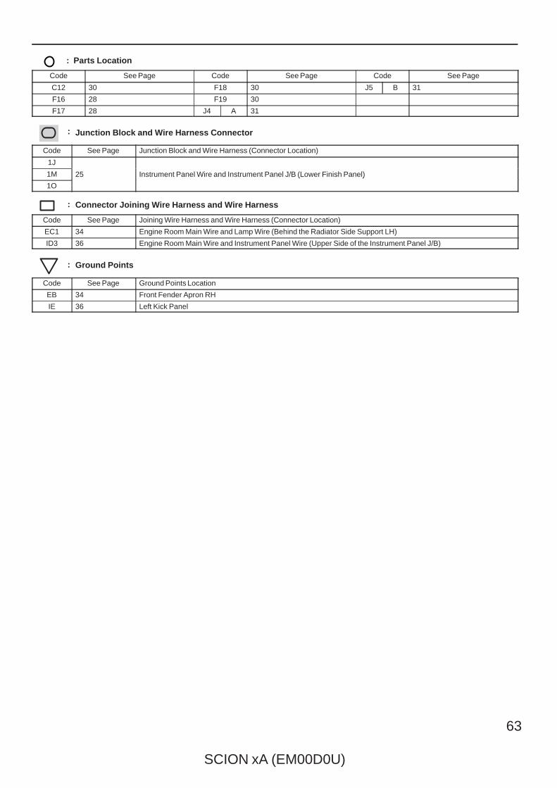
SCION xA (EM00D0U)
63
: Parts Location
Code See Page Code See Page Code See Page
C12 30 F18 30 J5 B 31
F16 28 F19 30
F17 28 J4 A 31
: Junction Block and Wire Harness Connector
Code See Page Junction Block and Wire Harness (Connector Location)
1J
25 Instrument Panel Wire and Instrument Panel J/B (Lower Finish Panel)1M 25 Instrument Panel Wire and Instrument Panel J/B (Lower Finish Panel)
1O
25 Instrument Panel Wire and Instrument Panel J/B (Lower Finish Panel)
: Connector Joining Wire Harness and Wire Harness
Code See Page Joining Wire Harness and Wire Harness (Connector Location)
EC1 34 Engine Room Main Wire and Lamp Wire (Behind the Radiator Side Support LH)
ID3 36 Engine Room Main Wire and Instrument Panel Wire (Upper Side of the Instrument Panel J/B)
: Ground Points
Code See Page Ground Points Location
EB 34 Front Fender Apron RH
IE 36 Left Kick Panel
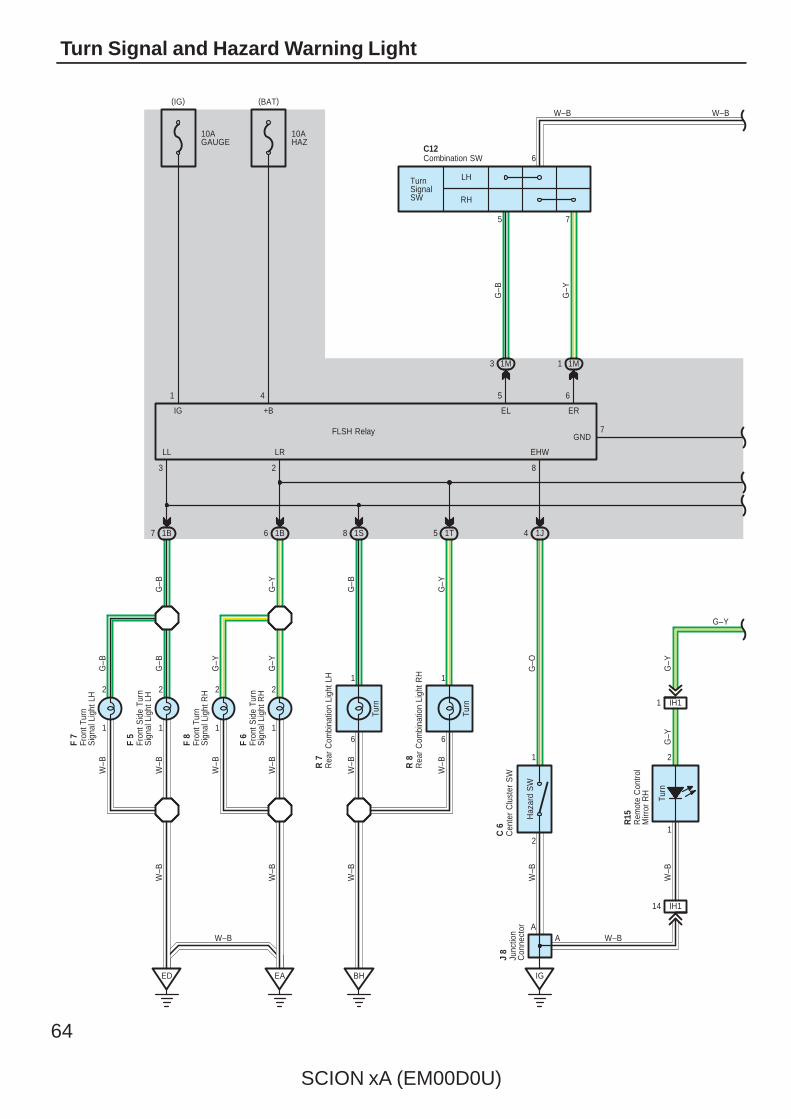
64
SCION xA (EM00D0U)
Turn Signal and Hazard Warning Light
1 1
10AGAUGE
FLSH Relay
10AHAZ
LH
RH
TurnSignalSW
6
1
6
1
ED EA BH
1B7 1B6 1S8 1T5
61 5
3
4
5
C12
7
7
1M11M3
2
W–B
W–B
W–B
W–B
W–B
G–B
G–Y
G–B
G–Y
G–B
G–Y
Turn
A
6
EL ER
GND
+BIG
LL LR
1J4
EHW
8
2
1
IG
G–O
W–B
W–B
W–B
Haz
ard
SW
2 2
1
2
1
2
G–B
G–B
G–Y
G–Y
W–B
W–B
W–B
W–B
Turn
Combination SW
Cen
ter
Clu
ster
SW
C 6
Rea
r C
ombi
natio
n Li
ght R
HR
8
Rea
r C
ombi
natio
n Li
ght L
HR
7
Fron
t Tur
nS
igna
l Lig
ht L
H
F 7
Fron
t Sid
e Tu
rnS
igna
l Lig
ht L
H
F 5
Fron
t Tur
nS
igna
l Lig
ht R
H
F 8
Fron
t Sid
e Tu
rnS
igna
l Lig
ht R
H
F 6
(BAT)(IG)
Junc
tion
Con
nect
or
J 8
A W–B
IH11
Turn
IH114
Rem
ote
Con
trol
Mirr
or R
H
R15
G–Y
G–Y
W–B
W–B
G–Y
1
2
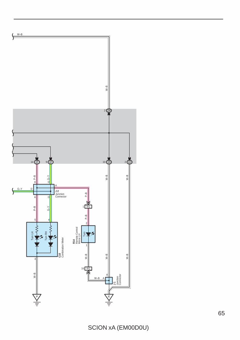
SCION xA (EM00D0U)
65
1F14 1F9 1N10
1M2
P–B
G–Y
W–B
W–B
W–B
W–B
1O2
IE
3
5 4
IF
W–B
Turn
LH
Turn
RH
C10
A
W–BCom
bina
tion
Met
er
IA11
Turn
IA116
Rem
ote
Con
trol
Mirr
or L
H
R14
P–B
P–B
W–B
Junc
tion
Con
nect
or
J 1
A D
D
A DA
JunctionConnector
J 2
W–B
G–Y
P–B
G–Y
AW–B
2
1
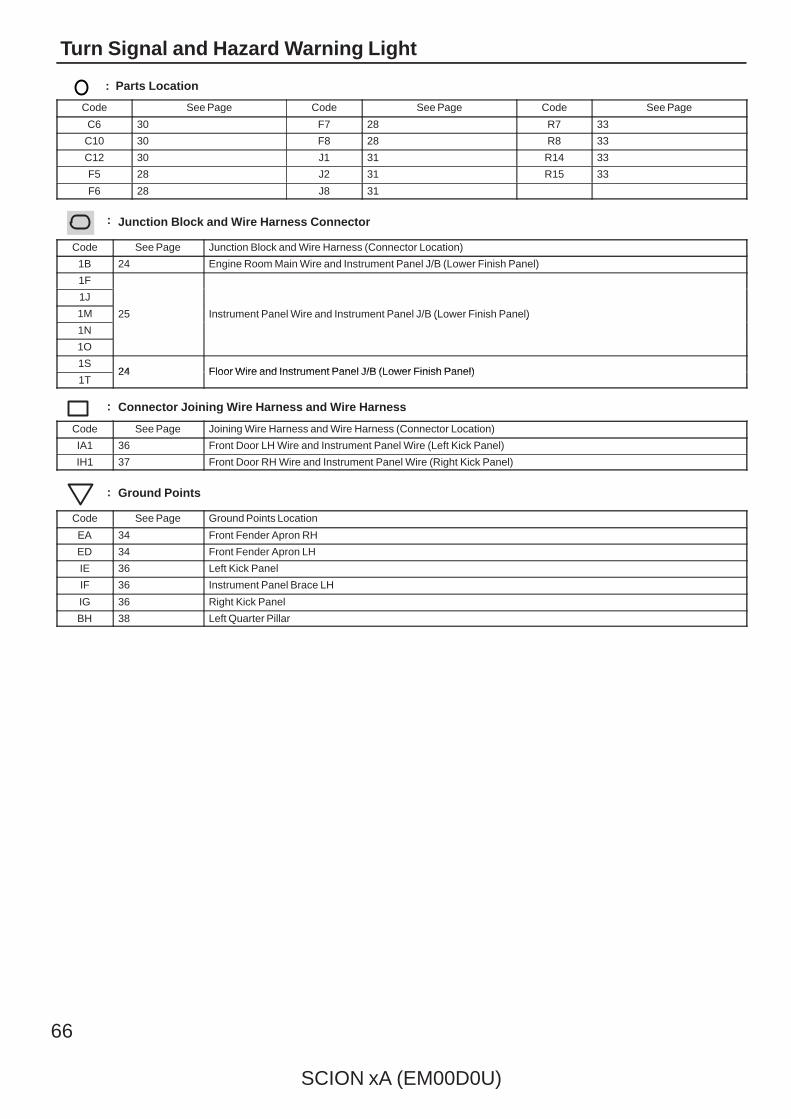
66
SCION xA (EM00D0U)
Turn Signal and Hazard Warning Light
: Parts Location
Code See Page Code See Page Code See Page
C6 30 F7 28 R7 33
C10 30 F8 28 R8 33
C12 30 J1 31 R14 33
F5 28 J2 31 R15 33
F6 28 J8 31
: Junction Block and Wire Harness Connector
Code See Page Junction Block and Wire Harness (Connector Location)
1B 24 Engine Room Main Wire and Instrument Panel J/B (Lower Finish Panel)
1F
25 Instrument Panel Wire and Instrument Panel J/B (Lower Finish Panel)
1J
25 Instrument Panel Wire and Instrument Panel J/B (Lower Finish Panel)1M 25 Instrument Panel Wire and Instrument Panel J/B (Lower Finish Panel)
1N
25 Instrument Panel Wire and Instrument Panel J/B (Lower Finish Panel)
1O
1S24 Floor Wire and Instrument Panel J/B (Lower Finish Panel)
1T24 Floor Wire and Instrument Panel J/B (Lower Finish Panel)
: Connector Joining Wire Harness and Wire Harness
Code See Page Joining Wire Harness and Wire Harness (Connector Location)
IA1 36 Front Door LH Wire and Instrument Panel Wire (Left Kick Panel)
IH1 37 Front Door RH Wire and Instrument Panel Wire (Right Kick Panel)
: Ground Points
Code See Page Ground Points Location
EA 34 Front Fender Apron RH
ED 34 Front Fender Apron LH
IE 36 Left Kick Panel
IF 36 Instrument Panel Brace LH
IG 36 Right Kick Panel
BH 38 Left Quarter Pillar

SCION xA (EM00D0U)
67
Memo
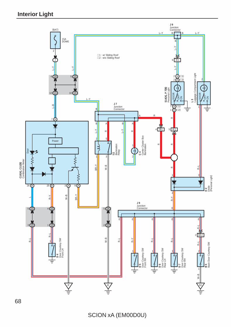
68
SCION xA (EM00D0U)
Interior Light
R–L
R–L
L–Y
2
1A4
1G12
R–Y
E
1
9
1G4
1S1
OFF
ON
DO
OR
1S5
1 1 1
R
A
L–B
R–L
R–L
R
W–B
BR
–Y
L–Y
D 6
D 7
D 5
E
R–L
R–Y
E
15ADOME
2
L–Y
∗ 2 : w/o Sliding Roof∗ 1 : w/ Sliding Roof
2
B B L–Y
B
L–Y
R–L
J 9
A7
B25 A3
L
1G
26
Power
B
5
Doo
r
IB14
(∗2)1 B
R–L
(∗1)7W
–BA
2
3 1S
(∗1)2
2 1O
5 1K
A
B 5
E
W–B
1
10 1K
(∗2)
J 7
DO
OR
ON
OFF
2 B
L–Y
IE16
S14(
A), P
7( B
)
BJ
2
1
2
3
5C
4
2
1
L–Y R
W–B
BR
–Y
ABAB
L–Y
B
1
RAI1
1
1
L–Y
E
IE
R
C10
( A) ,
C11
( B)
J 9D
2
R–Y
BE22
E
D 4
IF
IE15
R
Bac
k D
oor
Cou
rtesy
SW
Com
bina
tion
Met
er
Cen
ter
Clu
ster
Box
Illum
inat
ion
Doo
r C
ourte
sy S
WFr
ont L
H
Doo
r C
ourte
sy S
WFr
ont R
H
Doo
r C
ourte
sy S
WR
ear
LH
Doo
r C
ourte
sy S
WR
ear
RH
Dio
de( P
erso
nal L
ight
)
JunctionConnector
JunctionConnector
JunctionConnector
Illum
inat
ion
Rel
ay
Per
sona
l Lig
ht
R–L
3
L 3
Lugg
age
Com
partm
ent L
ight
(BAT)
R
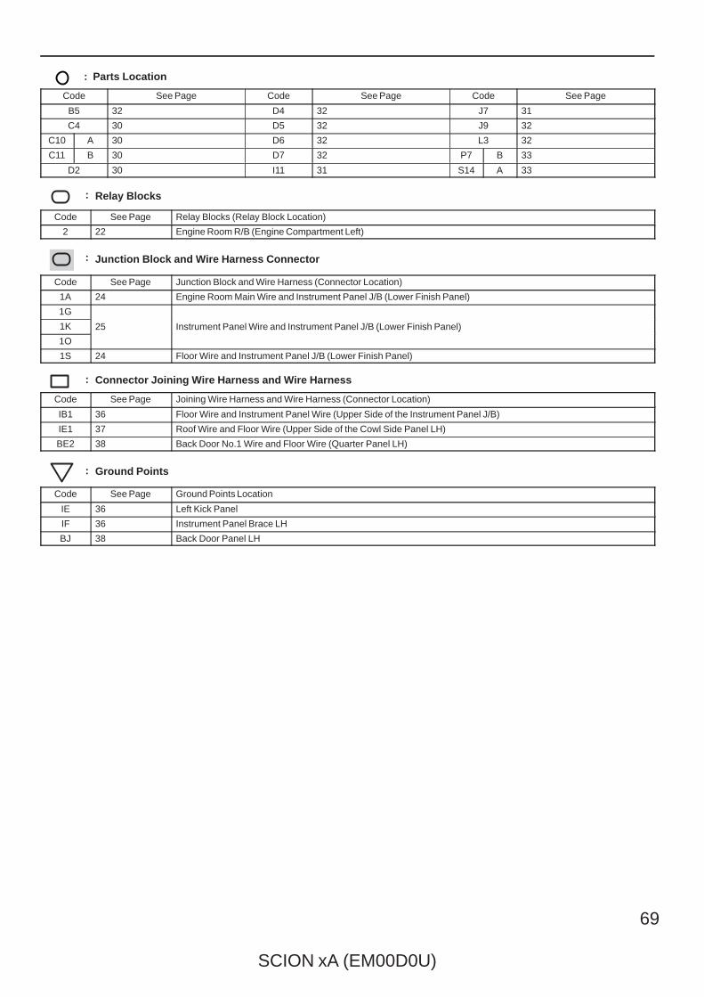
SCION xA (EM00D0U)
69
: Parts Location
Code See Page Code See Page Code See Page
B5 32 D4 32 J7 31
C4 30 D5 32 J9 32
C10 A 30 D6 32 L3 32
C11 B 30 D7 32 P7 B 33
D2 30 I11 31 S14 A 33
: Relay Blocks
Code See Page Relay Blocks (Relay Block Location)
2 22 Engine Room R/B (Engine Compartment Left)
: Junction Block and Wire Harness Connector
Code See Page Junction Block and Wire Harness (Connector Location)
1A 24 Engine Room Main Wire and Instrument Panel J/B (Lower Finish Panel)
1G
25 Instrument Panel Wire and Instrument Panel J/B (Lower Finish Panel)1K 25 Instrument Panel Wire and Instrument Panel J/B (Lower Finish Panel)
1O
25 Instrument Panel Wire and Instrument Panel J/B (Lower Finish Panel)
1S 24 Floor Wire and Instrument Panel J/B (Lower Finish Panel)
: Connector Joining Wire Harness and Wire Harness
Code See Page Joining Wire Harness and Wire Harness (Connector Location)
IB1 36 Floor Wire and Instrument Panel Wire (Upper Side of the Instrument Panel J/B)
IE1 37 Roof Wire and Floor Wire (Upper Side of the Cowl Side Panel LH)
BE2 38 Back Door No.1 Wire and Floor Wire (Quarter Panel LH)
: Ground Points
Code See Page Ground Points Location
IE 36 Left Kick Panel
IF 36 Instrument Panel Brace LH
BJ 38 Back Door Panel LH
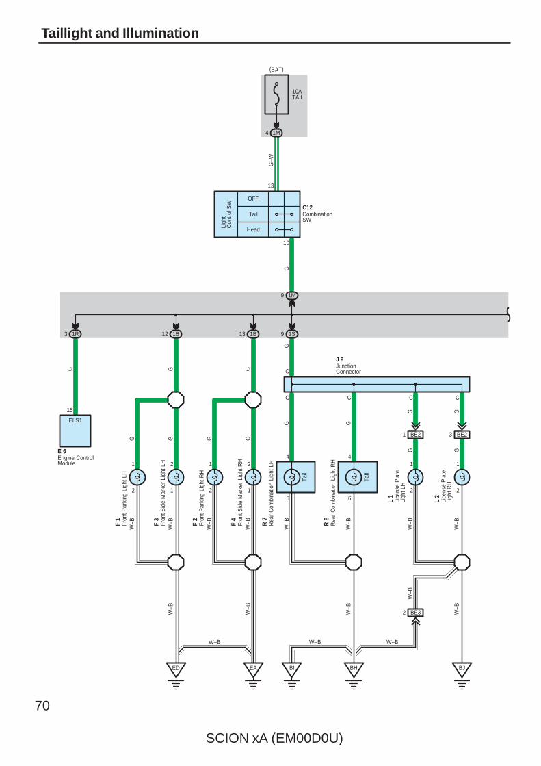
70
SCION xA (EM00D0U)
Taillight and Illumination
10ATAIL
1M4
OFF
Tail
Head
10
13
116
4
6
4
BHEAED
C
C
1B12 1B13 1S9
1M9
G
GG G
C
J 9
R 7
R 8
L 1
W–B
2
12
L 2
W–B
2
1
C C
W–B
Ligh
tC
ontro
l SW
G–W
G
2
2
1
2
1
GG
G G G GW
–B
W–B
W–B
W–B
W–B
W–B
F 1
F 3
F 2
F 4
W–B
W–B
W–B
BI
W–B
Tail
Tail
BE21 BE23
GG
G
W–B
W–B
BJ
W–B
C12CombinationSW
Fron
t Par
king
Lig
ht L
H
Fron
t Par
king
Lig
ht R
H
Fron
t Sid
e M
arke
r Li
ght L
H
Fron
t Sid
e M
arke
r Li
ght R
H
JunctionConnector
Lice
nse
Pla
teLi
ght L
H
Lice
nse
Pla
teLi
ght R
H
Rea
r C
ombi
natio
n Li
ght L
H
Rea
r C
ombi
natio
n Li
ght R
H
(BAT)
15
ELS1
G
Engine ControlModule
E 6
1R3
BE32
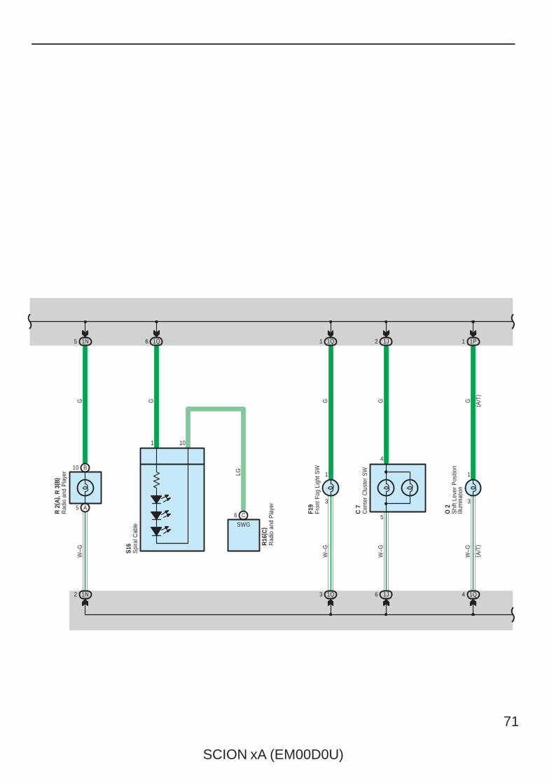
SCION xA (EM00D0U)
71
3
1
1P1
( A/T
)
G
( A/T
)
W–G
1Q41J61N2
5 1N 1J2
W–G
W–G
GG
R 2
( A) ,
R 3
( B)
5
4
C 7
O 2
Cen
ter
Clu
ster
SW
Shi
ft Le
ver
Pos
ition
Illum
inat
ion
Rad
io a
nd P
laye
r B10
A53
1
1Q1
GW
–G
1Q3
F19
Fron
t Fog
Lig
ht S
W
1Q6
G
Spi
ral C
able
S16
1 10
LG
C6
SWG
Rad
io a
nd P
laye
rR
16( C
)
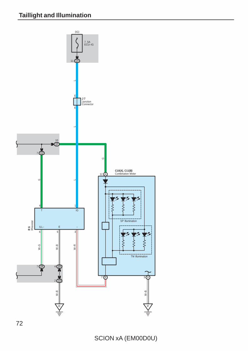
72
SCION xA (EM00D0U)
Taillight and Illumination
1R7 1R4
1O2
IE
SP Illumination
TM Illumination
IF
B7 A3
6 5 3
4 1
ILL– E –
T IG
W–G
W–B
W–R
W–B
1F10
1Q7
G
W–B
R 6
C10(A), C11(B)A12
G
7. 5AECU–IG
1H11
E
E
LL
L
J 7
Combination Meter
JunctionConnector
Rhe
osta
t(IG)
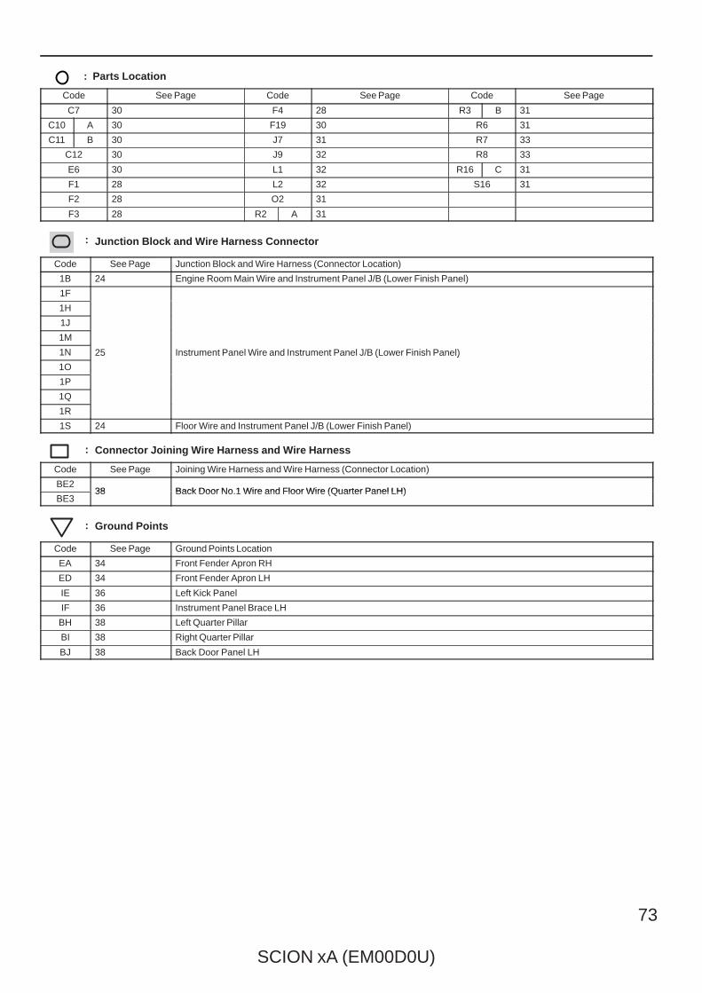
SCION xA (EM00D0U)
73
: Parts Location
Code See Page Code See Page Code See Page
C7 30 F4 28 R3 B 31
C10 A 30 F19 30 R6 31
C11 B 30 J7 31 R7 33
C12 30 J9 32 R8 33
E6 30 L1 32 R16 C 31
F1 28 L2 32 S16 31
F2 28 O2 31
F3 28 R2 A 31
: Junction Block and Wire Harness Connector
Code See Page Junction Block and Wire Harness (Connector Location)
1B 24 Engine Room Main Wire and Instrument Panel J/B (Lower Finish Panel)
1F
25 Instrument Panel Wire and Instrument Panel J/B (Lower Finish Panel)
1H
25 Instrument Panel Wire and Instrument Panel J/B (Lower Finish Panel)
1J
25 Instrument Panel Wire and Instrument Panel J/B (Lower Finish Panel)
1M
25 Instrument Panel Wire and Instrument Panel J/B (Lower Finish Panel)1N 25 Instrument Panel Wire and Instrument Panel J/B (Lower Finish Panel)
1O
25 Instrument Panel Wire and Instrument Panel J/B (Lower Finish Panel)
1P
1Q
1R
1S 24 Floor Wire and Instrument Panel J/B (Lower Finish Panel)
: Connector Joining Wire Harness and Wire Harness
Code See Page Joining Wire Harness and Wire Harness (Connector Location)
BE238 Back Door No.1 Wire and Floor Wire (Quarter Panel LH)
BE338 Back Door No.1 Wire and Floor Wire (Quarter Panel LH)
: Ground Points
Code See Page Ground Points Location
EA 34 Front Fender Apron RH
ED 34 Front Fender Apron LH
IE 36 Left Kick Panel
IF 36 Instrument Panel Brace LH
BH 38 Left Quarter Pillar
BI 38 Right Quarter Pillar
BJ 38 Back Door Panel LH
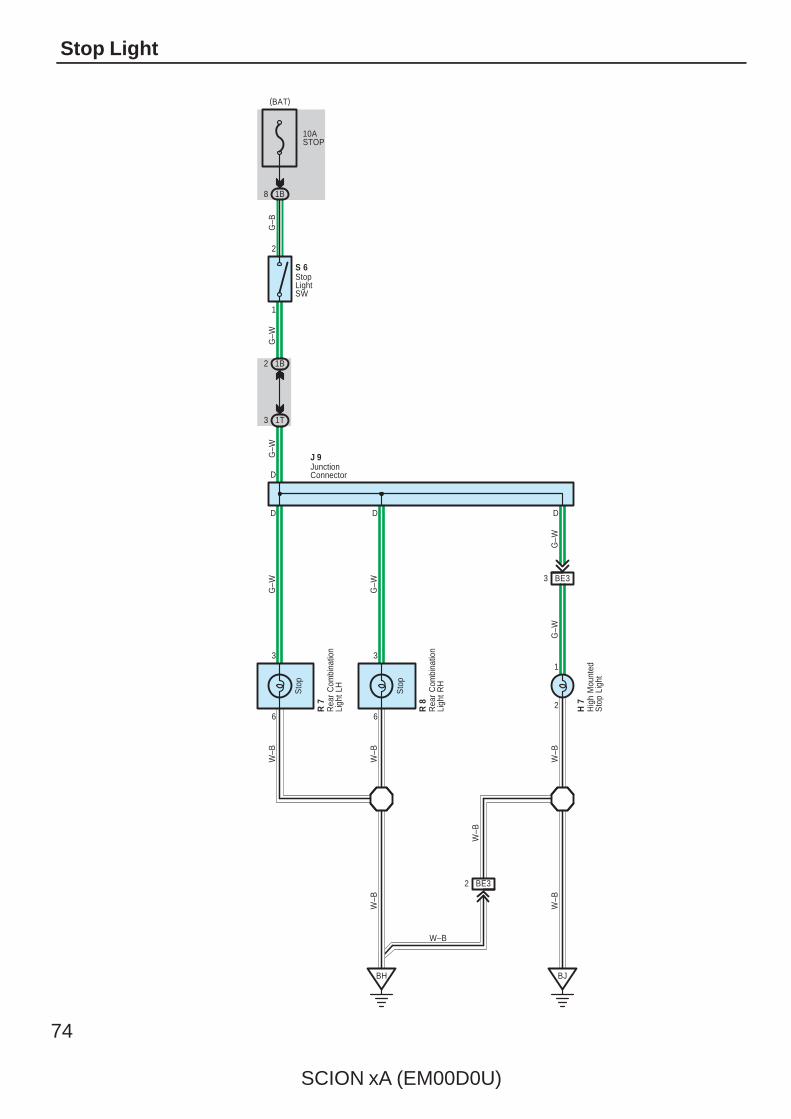
74
SCION xA (EM00D0U)
Stop Light
10ASTOP
1B8
1
2
1B2
1T3
D
G–W
W–B
6
3
6
3
D
D
BH
G–B
G–W
G–W
G–W
W–B
W–B
R 7
R 8
H 7
S 6G
–W
2
1
J 9
W–B
BJ
D
W–B
W–B
W–B
G–W
Sto
p
Sto
p
Hig
h M
ount
edS
top
Ligh
t
JunctionConnector
Rea
r C
ombi
natio
nLi
ght L
H
Rea
r C
ombi
natio
nLi
ght R
H
StopLightSW
BE32
BE33
(BAT)

SCION xA (EM00D0U)
75
: Parts Location
Code See Page Code See Page Code See Page
H7 32 R7 33 S6 31
J9 32 R8 33
: Junction Block and Wire Harness Connector
Code See Page Junction Block and Wire Harness (Connector Location)
1B 24 Engine Room Main Wire and Instrument Panel J/B (Lower Finish Panel)
1T 24 Floor Wire and Instrument Panel J/B (Lower Finish Panel)
: Connector Joining Wire Harness and Wire Harness
Code See Page Joining Wire Harness and Wire Harness (Connector Location)
BE3 38 Back Door No.1 Wire and Floor Wire (Quarter Panel LH)
: Ground Points
Code See Page Ground Points Location
BH 38 Left Quarter Pillar
BJ 38 Back Door Panel LH
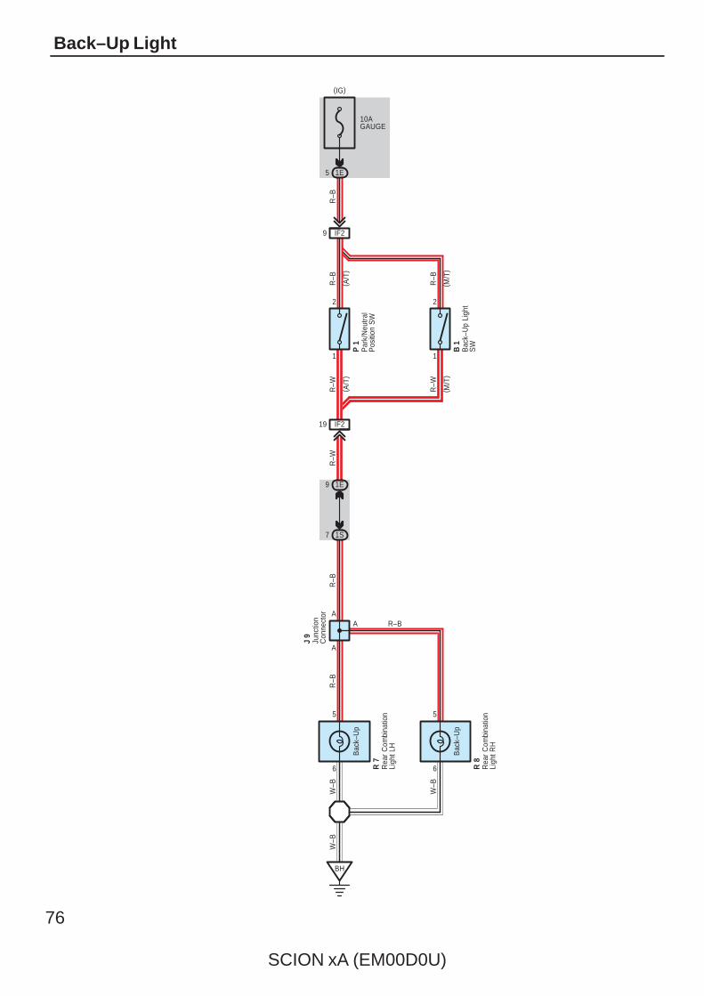
76
SCION xA (EM00D0U)
Back–Up Light
10AGAUGE
1E5
R–W
R–B
1E9
1S7
A
W–B
BH
W–B
R–W
R–W
R–B
R–B
R–B
R–B
R–B
1
19 IF2
5
6 R 7
Bac
k–U
p
IF29
A
6
Bac
k–U
p
A
5
R 8
1
2 2
( A/T
)( A
/T)
( M/T
)( M
/T)
B 1
P 1
W–B
J 9
Bac
k–U
p Li
ght
SW
Junc
tion
Con
nect
or
Par
k/N
eutra
lP
ositi
on S
W
Rea
r C
ombi
natio
nLi
ght L
H
Rea
r C
ombi
natio
nLi
ght R
H
(IG)
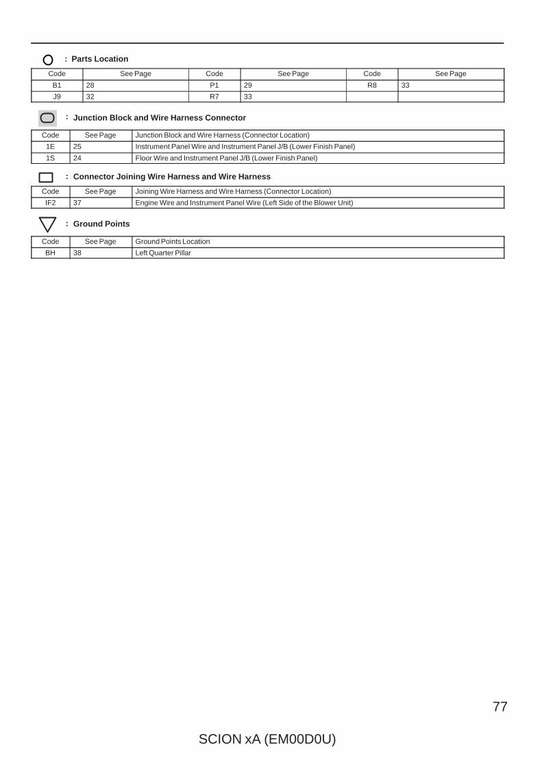
SCION xA (EM00D0U)
77
: Parts Location
Code See Page Code See Page Code See Page
B1 28 P1 29 R8 33
J9 32 R7 33
: Junction Block and Wire Harness Connector
Code See Page Junction Block and Wire Harness (Connector Location)
1E 25 Instrument Panel Wire and Instrument Panel J/B (Lower Finish Panel)
1S 24 Floor Wire and Instrument Panel J/B (Lower Finish Panel)
: Connector Joining Wire Harness and Wire Harness
Code See Page Joining Wire Harness and Wire Harness (Connector Location)
IF2 37 Engine Wire and Instrument Panel Wire (Left Side of the Blower Unit)
: Ground Points
Code See Page Ground Points Location
BH 38 Left Quarter Pillar
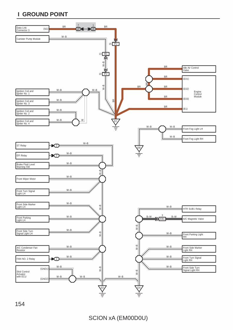
154
SCION xA (EM00D0U)
I GROUND POINT
W–B
W–B
11E
BR
ED
BRData LinkConnector 3
(E01)
(E02)
(E03)
Front Parking LightRH
Front Side MarkerLight RH
Ignition Coil andIgniter No. 1
ST Relay
Brake Fluid LevelWarning SW
Front Wiper Motor
Front ParkingLight LH
A/C Condenser FanResistor
FAN NO. 2 Relay
Skid ControlActuatorwith ECU
W–B
2
2
EA
Front Side TurnSignal Light LH
EC
W–B
W–B
W–B
W–B
W–B
W–B
W–B
W–B
W–B
Front Side MarkerLight LH
W–B
W–BFront Turn SignalLight LH
W–B
W–B
W–B
IF215
1P7
BR
BR
W–B
BR
BR
BR
W–B
(GND1)
(GND2)
EFI RelayW–B
(SG)
Ignition Coil andIgniter No. 3
W–B
Ignition Coil andIgniter No. 2
W–B
Ignition Coil andIgniter No. 4
W–B
W–B
2
BR(E1)
W–B
Idle Air ControlValve
BR
BR
W
EngineControlModule
W–B
W–B
W–B
W–B
Front Turn SignalLight RH
Front Side TurnSignal Light RH
Canister Pump Module
IF210
IB113
W–B
W–B
W–B
Front Fog Light LH
Front Fog Light RH
A/C Magnetic Valve
HTR SUB1 Relay
EB13
W–B
B–W
EB
W–B W–B
W–BW
–B
B–W
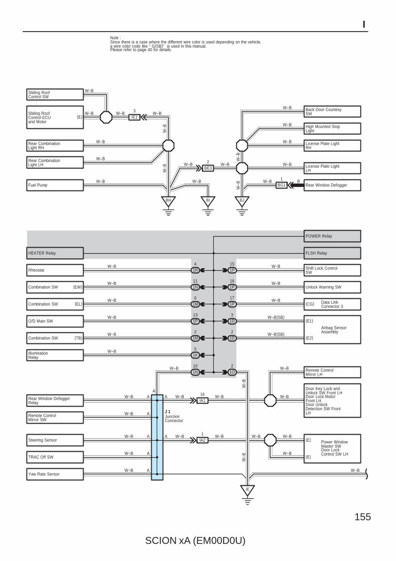
SCION xA (EM00D0U)
155
I
BH
Door LockControl SW LH
W–BIlluminationRelay
W–B1P
W–B
W–B
W–B
W–BA
A
A
IE13
1K5
Shift Lock ControlSW
W–B
W–B
A
AW–B
W–B
IE
1IA2
Door Key Lock andUnlock SW Front LH
Power WindowMaster SW
TRAC Off SW
Steering Sensor
Rear Window DefoggerRelay
Remote ControlMirror SW
IA116
W–B
W–BW–B
W–B
13
Rear CombinationLight LH License Plate Light
LH
1P
POWER Relay
FLSH Relay
Combination SW
W–B
Unlock Warning SW
(CG)
(E1)
(E2)
Rear CombinationLight RH
Fuel Pump
Rheostat
Combination SW
1N10
1D2
1D3
1P17
1P16
1N11
W–B
W–B(SB)
W–B
W–B
W–B(SB)
W–B
W–B
Airbag SensorAssembly
Data LinkConnector 3
1R4
(EW)
Yaw Rate SensorW–B
(TB)
(EL)
BRear Window Defogger
HEATER Relay
W–B
1O2
A
Sliding RoofControl ECUand Motor
Sliding RoofControl SW
1M6W–B
O/D Main SWW–B
15
AW–B
W–B
W–B(E)
(E)
W–B
BJ
W–B
W–B W–B
W–B
Combination SW2
1MW–B
W–BW–B
BI
License Plate LightRH
High Mounted StopLight
Back Door CourtesySW
W–B
W–B
W–B
W–B
W–B
BG11
W–B
Door Lock MotorFront LHDoor UnlockDetection SW FrontLH
W–B(E)
J 1JunctionConnector
A
BE32
Remote ControlMirror LH
W–B
W–B
W–B
W–B
Note : Since there is a case where the different wire color is used depending on the vehicle, a wire color code like " G(SB)" is used in this manual. Please refer to page 40 for details.
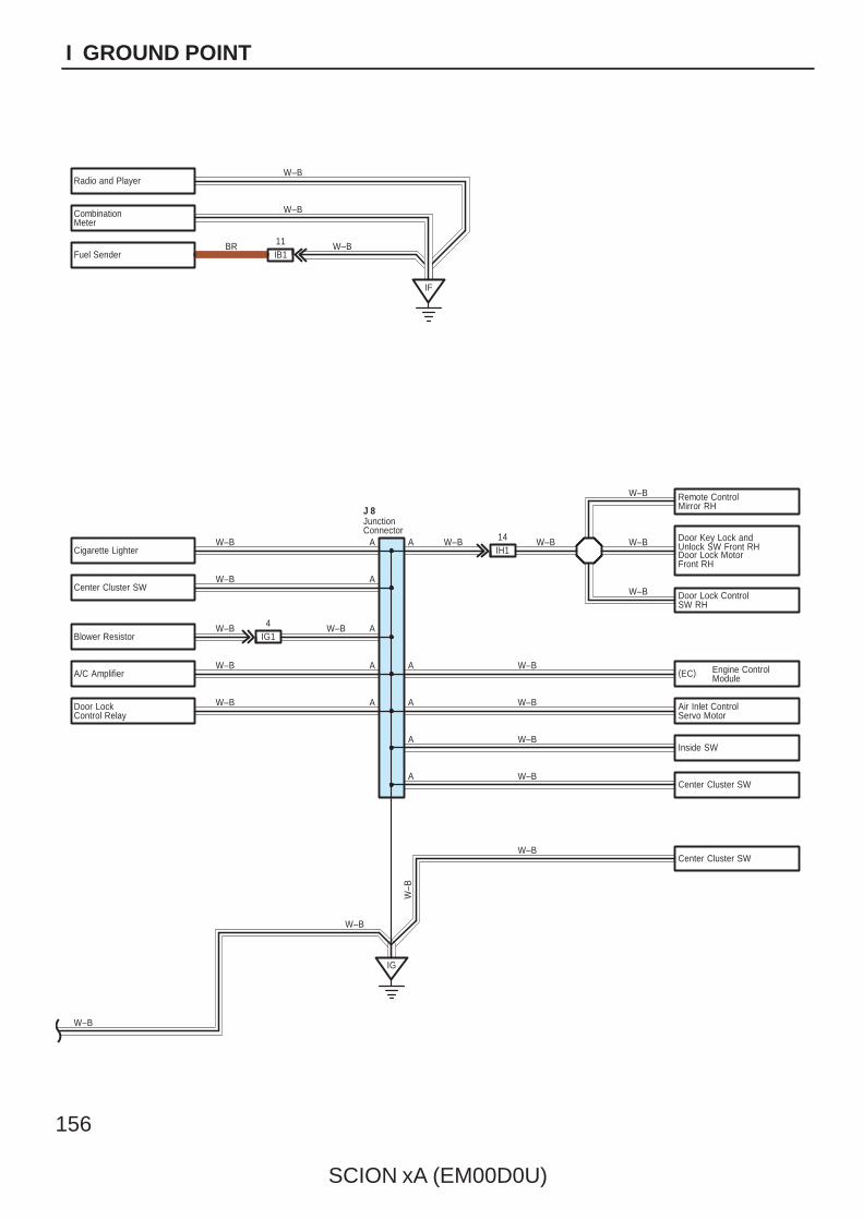
156
SCION xA (EM00D0U)
I GROUND POINT
IF
IG
Radio and Player
Door LockControl Relay
Air Inlet ControlServo Motor
Door Lock MotorFront RH
W–B
IH114 W–B
Door Lock ControlSW RH
Center Cluster SW
A
A
W–B
A
W–B
W–B
W–B W–B
J 8
W–BA
W–B
W–B
W–B
W–B
W–B
Center Cluster SW
A
CombinationMeter
Cigarette Lighter
IB111
Fuel Sender
Blower Resistor
Center Cluster SW
W–B
W–B
W–B A
A
A
W–B
Door Key Lock andUnlock SW Front RH
JunctionConnector
IG14 W–B
A/C Amplifier
AInside SW
W–B
BR
W–B
Remote ControlMirror RH
W–B
(EC) Engine ControlModule
W–BA
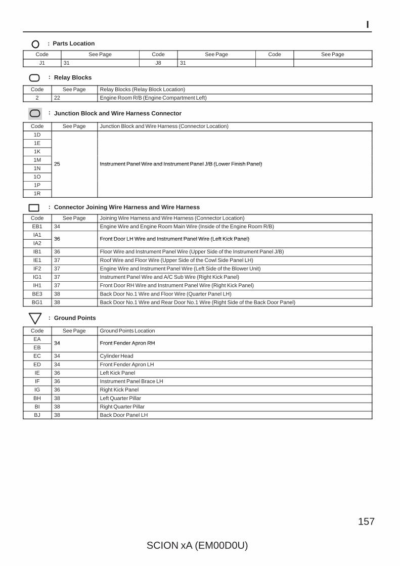
SCION xA (EM00D0U)
157
I
: Parts Location
Code See Page Code See Page Code See Page
J1 31 J8 31
: Relay Blocks
Code See Page Relay Blocks (Relay Block Location)
2 22 Engine Room R/B (Engine Compartment Left)
: Junction Block and Wire Harness Connector
Code See Page Junction Block and Wire Harness (Connector Location)
1D
25 Instrument Panel Wire and Instrument Panel J/B (Lower Finish Panel)
1E
25 Instrument Panel Wire and Instrument Panel J/B (Lower Finish Panel)
1K
25 Instrument Panel Wire and Instrument Panel J/B (Lower Finish Panel)1M
25 Instrument Panel Wire and Instrument Panel J/B (Lower Finish Panel)1N
25 Instrument Panel Wire and Instrument Panel J/B (Lower Finish Panel)
1O
1P
1R
: Connector Joining Wire Harness and Wire Harness
Code See Page Joining Wire Harness and Wire Harness (Connector Location)
EB1 34 Engine Wire and Engine Room Main Wire (Inside of the Engine Room R/B)
IA136 Front Door LH Wire and Instrument Panel Wire (Left Kick Panel)
IA236 Front Door LH Wire and Instrument Panel Wire (Left Kick Panel)
IB1 36 Floor Wire and Instrument Panel Wire (Upper Side of the Instrument Panel J/B)
IE1 37 Roof Wire and Floor Wire (Upper Side of the Cowl Side Panel LH)
IF2 37 Engine Wire and Instrument Panel Wire (Left Side of the Blower Unit)
IG1 37 Instrument Panel Wire and A/C Sub Wire (Right Kick Panel)
IH1 37 Front Door RH Wire and Instrument Panel Wire (Right Kick Panel)
BE3 38 Back Door No.1 Wire and Floor Wire (Quarter Panel LH)
BG1 38 Back Door No.1 Wire and Rear Door No.1 Wire (Right Side of the Back Door Panel)
: Ground Points
Code See Page Ground Points Location
EA34 Front Fender Apron RH
EB34 Front Fender Apron RH
EC 34 Cylinder Head
ED 34 Front Fender Apron LH
IE 36 Left Kick Panel
IF 36 Instrument Panel Brace LH
IG 36 Right Kick Panel
BH 38 Left Quarter Pillar
BI 38 Right Quarter Pillar
BJ 38 Back Door Panel LH
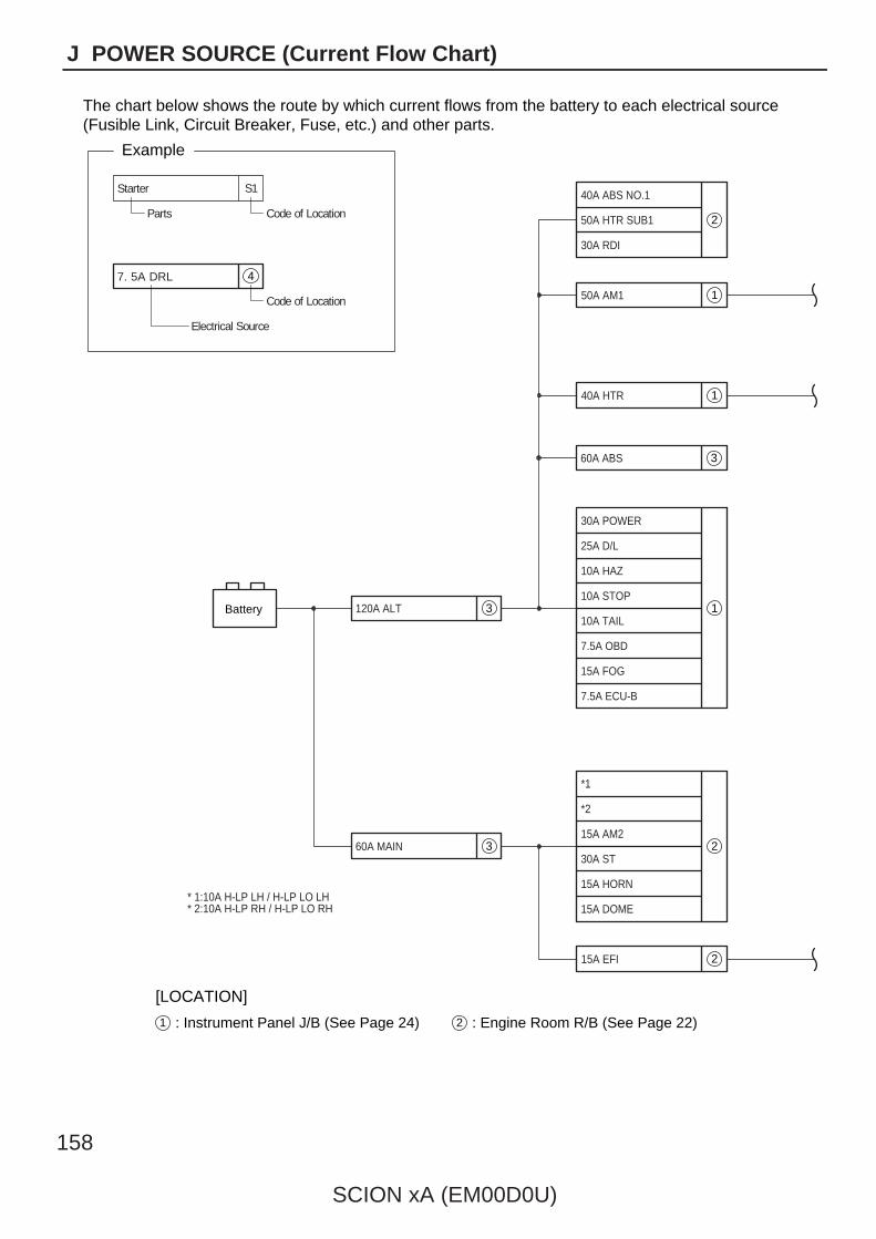
158
SCION xA (EM00D0U)
J POWER SOURCE (Current Flow Chart)
The chart below shows the route by which current flows from the battery to each electrical source(Fusible Link, Circuit Breaker, Fuse, etc.) and other parts.
4
S1Starter
Parts Code of Location
7. 5A DRL
Code of Location
Electrical Source
Example
50A HTR SUB1
40A ABS NO.1
30A RDI
50A AM1
30A POWER
25A D/L
10A HAZ
10A STOP
10A TAIL
7.5A OBD
15A FOG
7.5A ECU-B
*1
* 1:10A H-LP LH / H-LP LO LH* 2:10A H-LP RH / H-LP LO RH
*2
15A AM2
30A ST
15A HORN
15A DOME
60A MAIN
120A ALTBattery 3
2
1
40A HTR 1
60A ABS 3
15A EFI 2
1
23
1 : Instrument Panel J/B (See Page 24) 2 : Engine Room R/B (See Page 22)
[LOCATION]
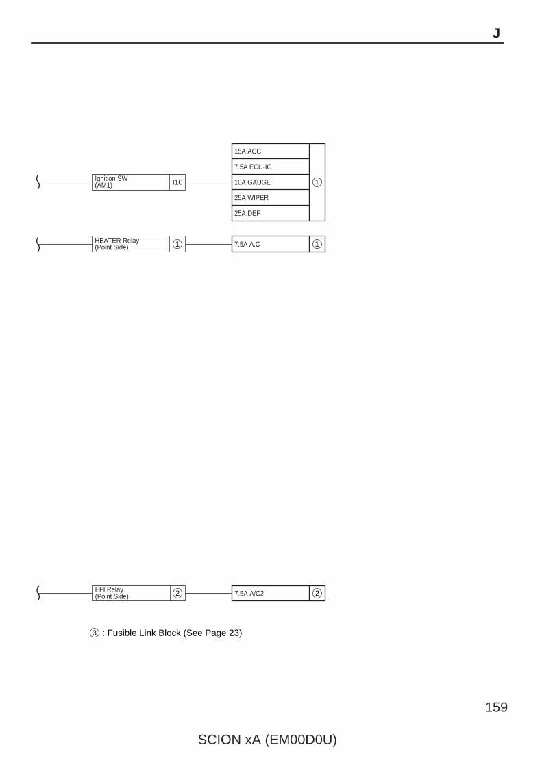
SCION xA (EM00D0U)
159
J
3 : Fusible Link Block (See Page 23)
15A ACC
7.5A ECU-IG
10A GAUGE
25A WIPER
25A DEF
Ignition SW(AM1) I10 1
7.5A A.CHEATER Relay(Point Side) 11
7.5A A/C2EFI Relay(Point Side) 22
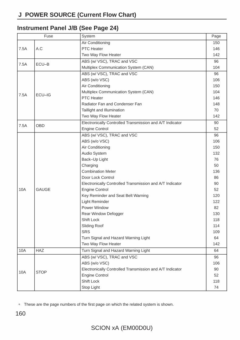
160
SCION xA (EM00D0U)
J POWER SOURCE (Current Flow Chart)
Instrument Panel J/B (See Page 24)Fuse System Page
7.5A A.C
Air Conditioning
PTC Heater
Two Way Flow Heater
150
146
142
7.5A ECU–BABS (w/ VSC), TRAC and VSC
Multiplex Communication System (CAN)
96
104
7.5A ECU–IG
ABS (w/ VSC), TRAC and VSC
ABS (w/o VSC)
Air Conditioning
Multiplex Communication System (CAN)
PTC Heater
Radiator Fan and Condenser Fan
Taillight and Illumination
Two Way Flow Heater
96
106
150
104
146
148
70
142
7.5A OBDElectronically Controlled Transmission and A/T Indicator
Engine Control
90
52
10A GAUGE
ABS (w/ VSC), TRAC and VSC
ABS (w/o VSC)
Air Conditioning
Audio System
Back–Up Light
Charging
Combination Meter
Door Lock Control
Electronically Controlled Transmission and A/T Indicator
Engine Control
Key Reminder and Seat Belt Warning
Light Reminder
Power Window
Rear Window Defogger
Shift Lock
Sliding Roof
SRS
Turn Signal and Hazard Warning Light
Two Way Flow Heater
96
106
150
132
76
50
136
86
90
52
120
122
82
130
118
114
109
64
142
10A HAZ Turn Signal and Hazard Warning Light 64
10A STOP
ABS (w/ VSC), TRAC and VSC
ABS (w/o VSC)
Electronically Controlled Transmission and A/T Indicator
Engine Control
Shift Lock
Stop Light
96
106
90
52
118
74
∗ These are the page numbers of the first page on which the related system is shown.
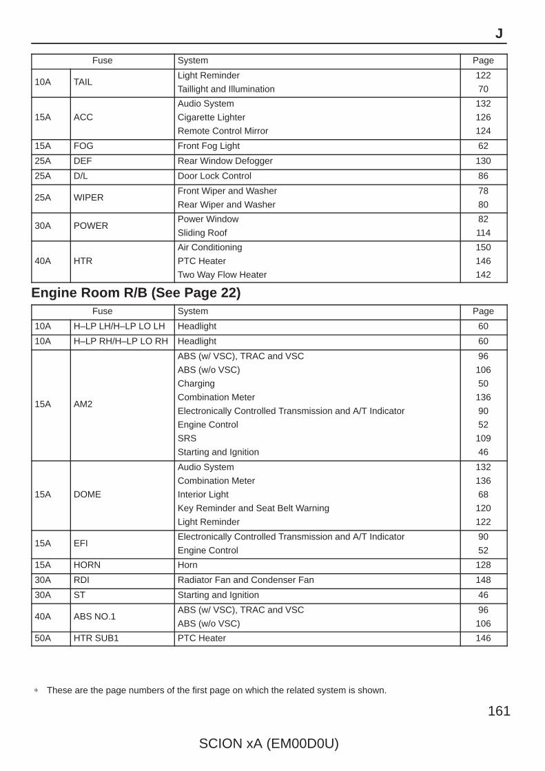
SCION xA (EM00D0U)
161
J
Fuse System Page
10A TAILLight Reminder
Taillight and Illumination
122
70
15A ACC
Audio System
Cigarette Lighter
Remote Control Mirror
132
126
124
15A FOG Front Fog Light 62
25A DEF Rear Window Defogger 130
25A D/L Door Lock Control 86
25A WIPERFront Wiper and Washer
Rear Wiper and Washer
78
80
30A POWERPower Window
Sliding Roof
82
114
40A HTR
Air Conditioning
PTC Heater
Two Way Flow Heater
150
146
142
Engine Room R/B (See Page 22)Fuse System Page
10A H–LP LH/H–LP LO LH Headlight 60
10A H–LP RH/H–LP LO RH Headlight 60
15A AM2
ABS (w/ VSC), TRAC and VSC
ABS (w/o VSC)
Charging
Combination Meter
Electronically Controlled Transmission and A/T Indicator
Engine Control
SRS
Starting and Ignition
96
106
50
136
90
52
109
46
15A DOME
Audio System
Combination Meter
Interior Light
Key Reminder and Seat Belt Warning
Light Reminder
132
136
68
120
122
15A EFIElectronically Controlled Transmission and A/T Indicator
Engine Control
90
52
15A HORN Horn 128
30A RDI Radiator Fan and Condenser Fan 148
30A ST Starting and Ignition 46
40A ABS NO.1ABS (w/ VSC), TRAC and VSC
ABS (w/o VSC)
96
106
50A HTR SUB1 PTC Heater 146
∗ These are the page numbers of the first page on which the related system is shown.

162
SCION xA (EM00D0U)
J POWER SOURCE (Current Flow Chart)
Fusible Link Block (See Page 23)Fuse System Page
60A ABSABS (w/ VSC), TRAC and VSC
ABS (w/o VSC)
96
106
60A MAIN
ABS (w/ VSC), TRAC and VSC
ABS (w/o VSC)
Charging
Combination Meter
Electronically Controlled Transmission and A/T Indicator
Engine Control
SRS
Starting and Ignition
96
106
50
136
90
52
109
46
120A ALT
ABS (w/ VSC), TRAC and VSC
ABS (w/o VSC)
Charging
96
106
50
∗ These are the page numbers of the first page on which the related system is shown.

SCION xA (EM00D0U)
163
Memo
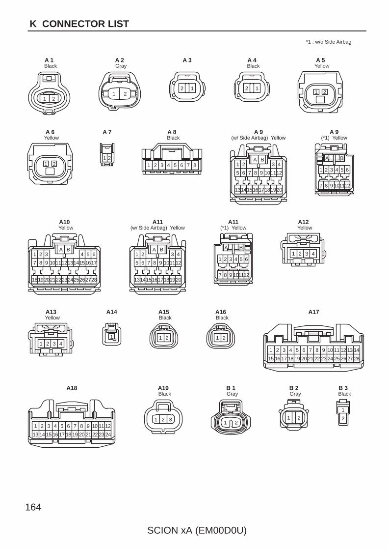
164
SCION xA (EM00D0U)
K CONNECTOR LIST
21
BlackA 1
1 2
GrayA 2
12
A 3
12
BlackA 4
1 2
YellowA 5
1 2
YellowA 6
21
A 7
2 3 4 5 6 7 81
BlackA 8
171819161415 20
1 2 3 4
5 6 7 8 9 101112
13
A B
(w/ Side Airbag) YellowA 9
1 2 3 4 5 6
7 8 9 101112
A B
(*1) YellowA 9
242523 26222021 2827
1 2 3 4 5 6
7 8 9 1011121314151617
1819
A B
YellowA10
171819161415 20
1 2 3 4
5 6 7 8 9 101112
13
A B
(w/ Side Airbag) YellowA11
1 2 3 4 5 6
7 8 9 101112
A B
(*1) YellowA11
1 2 3 4
YellowA12
1 2 3 4
YellowA13
1
A14
1 2
BlackA15
1 2
BlackA16
21
15 16
4
18
5
19
6
20
7
21
8
22
9
23
10
24
11
25
13
27
14
28
3
17
12
26
A17
21
13 14
3
15
4
16
5
17
6
18
7
19
8
20
9
21
10
22
11
23
12
24
A18
1 2 3
BlackA19
1 2
GrayB 1
1 2
GrayB 2
1
2
BlackB 3
*1 : w/o Side Airbag
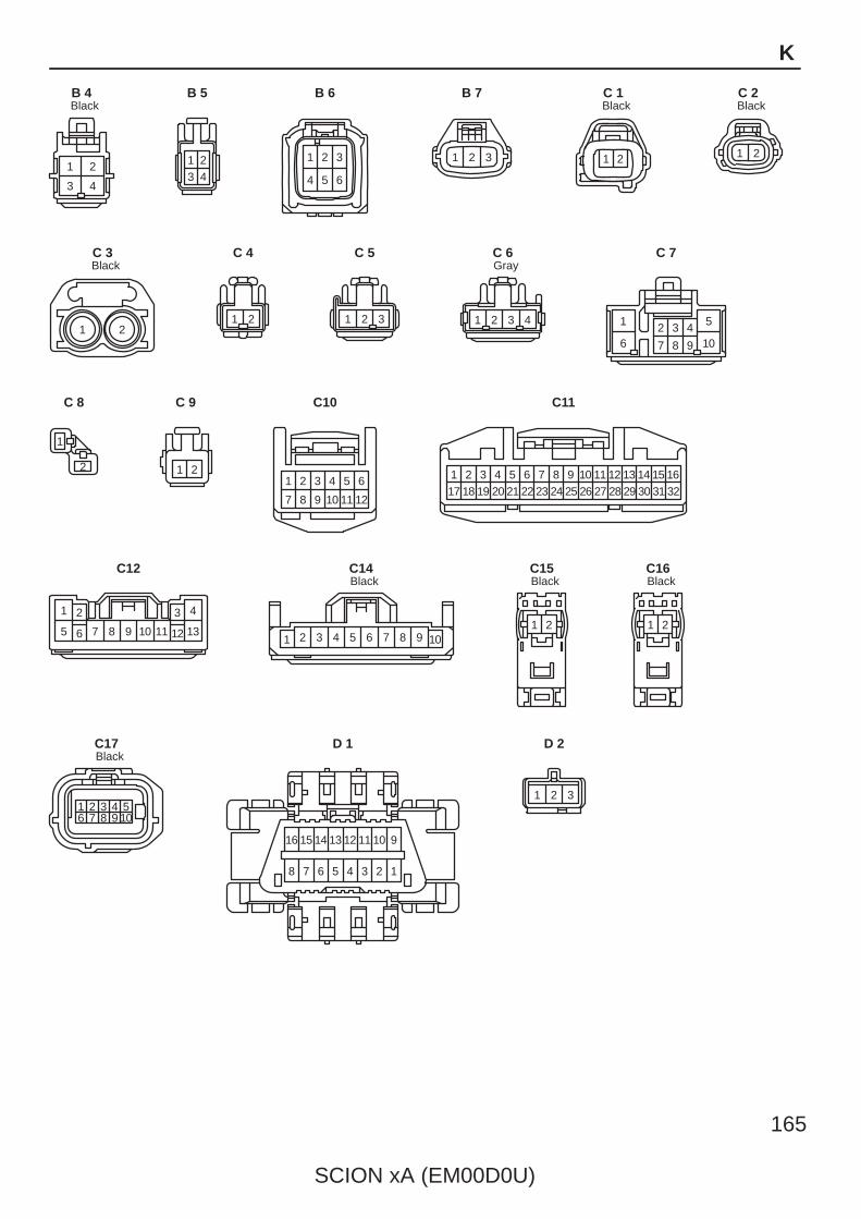
SCION xA (EM00D0U)
165
K
1 2
3 4
BlackB 4
23 41
B 5
1 2 3
4 5 6
B 6
1 2 3
B 7
1 2
BlackC 1
1 2
BlackC 2
1 2
BlackC 3
1 2
C 4
1 32
C 5
1 2 3 4
GrayC 6
1 2 3 4 5
6 7 8 9 10
C 7
1
2
C 8
1 2
C 9
7 8
1 2
12
4 5 6
9 1110
3
C10
418
317 201
211952
226
237
259
2610
2711
2812
2913
3014
3115
3216
248
C11
1 2 3 4
5 6 7 8 9 10 11 12 13
C12
1 2 3 4 5 6 7 8 9 10
BlackC14
21
BlackC15
21
BlackC16
1 2 3 4 56 7 8 9 10
BlackC17
16 15 14 13 12 11 10 9
8 7 6 5 4 3 2 1
D 1
1 2 3
D 2

166
SCION xA (EM00D0U)
K CONNECTOR LIST
21 3 4 5 6 7 8 9 101112 13
14 15 16171819 2021222324 25
D 3
1
D 4
1
D 5
1
D 6
1
D 7
1 2 3 4
5 6 7 8 9 10
D 8
1 2 3 4
5 6 7 8 9 10
D 9
6 95 8
14
7
15
4
17
21
1816
3
11 1310 12
D10
1 2
3 4 5 6
D11
1 2 3 4
5 6 7 8 9 10
D12
1 2 3 4
5 6 7 8 9 10
D13
1 2 3 4 5
6 7 8 9 10
GrayE 1
21
GrayE 2
1
17
29 3428
1918
98
20
10
21
33
11
76
13 14 15 16
22 23 26
12
432 5
2724 25
30 31 32
E 3
1
19
333231 3528
2320
118 12
34
13
76
15 16 17 18
24 25 26
14
432 5
27
29
21
9
30
22
10
E 4
16
3231 3528
2017
9 10
34
11
65
13 14 15
23 24 26
12
321 4
27
29
18
7
30
19
8
21 22 25
33
E 5
1
17
292827 3126
1918
98
20
10
21
30
11
76
13 14 15 16
22 23 24
12
432 5
25
E 6
1 2
BrownF 1
1 2
BrownF 2
1 2
F 3
1 2
F 4

SCION xA (EM00D0U)
167
K
1 2
GrayF 5
1 2
GrayF 6
1 2
GrayF 7
1 2
GrayF 8
1 2 3
4 5
BlackF 9
BlackF10
(See Page 23)
11
BlackF11
1 32
F12
1
2
GrayF13
1
2
GrayF14
1 2 3
4 5
Dark GrayF15
21
BlackF16
21
BlackF17
35
1 2
F18
1 2 3 4
BlackF19
1
G 1
1 2 3
BlackG 2
1
2 3
H 1
1
2 3
H 2
1 2
3 4
GrayH 3
1
BlackH 4
1
BlackH 5
21
3 4
GrayH 6
1 2
H 7
1 2 3
BlackI 1
1 2 3 4
BlackI 2
1 2 3 4
GrayI 3
1 2 3 4
BlackI 4
1 2 3 4
GrayI 5
1 2
BlackI 6
1 2
GrayI 7
1 2
BlackI 8
1 2
GrayI 9
1 24 5
36
I10
35
1 2
I11
23 41
I12
A A A AA A A A A A A
J 1
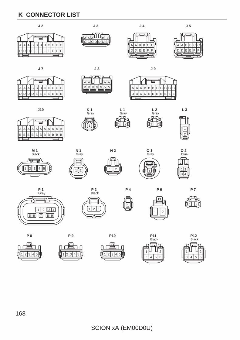
168
SCION xA (EM00D0U)
K CONNECTOR LIST
A
BB
AA
BB
AA
BB
AA
BB
AA
BB
A A
B
C
EE
CC
EE
CC
EE
BB
ED
BA
DD
A A
D
A A A AA A A A A A AC
EE
CC
EE
CC
EE
BB
ED
BA
DD
A A
D
A A B B C C
D D E E F F
C
FF
CC
FF
CB
EE
BB
EE
BA
DD
A A
D
J 2
BBAAAC C C D D D B
J 3
A A B B C C
D D E E F F
J 4 J 5
J 7 J 8 J 9
J10
1
GrayK 1
1 2
GrayL 1
1 2
GrayL 2
1
2
L 3
54321
BlackM 1
1 2
GrayN 1
1 2
N 2
1
GrayO 1
23 41
BlueO 2
87 9
21 3 4
65
GrayP 1
1 2 3
BlackP 2
1
P 4
1 2
P 6
1 2
P 7
1 2 3 4 5
P 8
1 2 3 4 5
P 9
1 2 3 4 5
P10
1 2
3 4 5 6
BlackP11
1 2
3 4 5 6
BlackP12
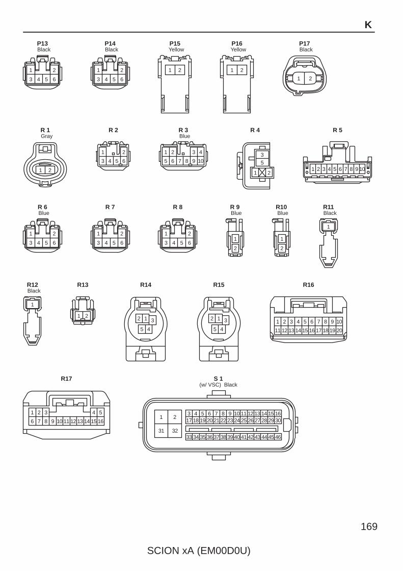
SCION xA (EM00D0U)
169
K
1 2
3 4 5 6
BlackP13
1 2
3 4 5 6
BlackP14
21
YellowP15
21
YellowP16
1 2
BlackP17
21
GrayR 1
1 2
3 4 5 6
R 2
1 2 3 4
5 6 7 8 9 10
BlueR 3
3
5
1 2
R 4
1 2 3 4 5 6 7 8 9 10
R 5
1 2
3 4 5 6
BlueR 6
1 2
3 4 5 6
R 7
1 2
3 4 5 6
R 8
1
2
BlueR 9
1
2
BlueR10
1
BlackR11
1
BlackR12
1 2
R13
2 1 3
5 4
R14
2 1 3
5 4
R15
1 2 3 4 5 6 7 8 9 10
11 12 13 14 15 16 17 18 19 20
R16
1
6
2
7
3
8 9 10 11 12 13 14
4
15
5
16
R17
31 32
213 4 5 6 7 8 9 10 11 12 13 14 15 1617 18 19 20 21 22 23 24 25 26 27 28 29 30
33 34 35 36 37 38 39 40 41 42 43 44 45 46
(w/ VSC) BlackS 1
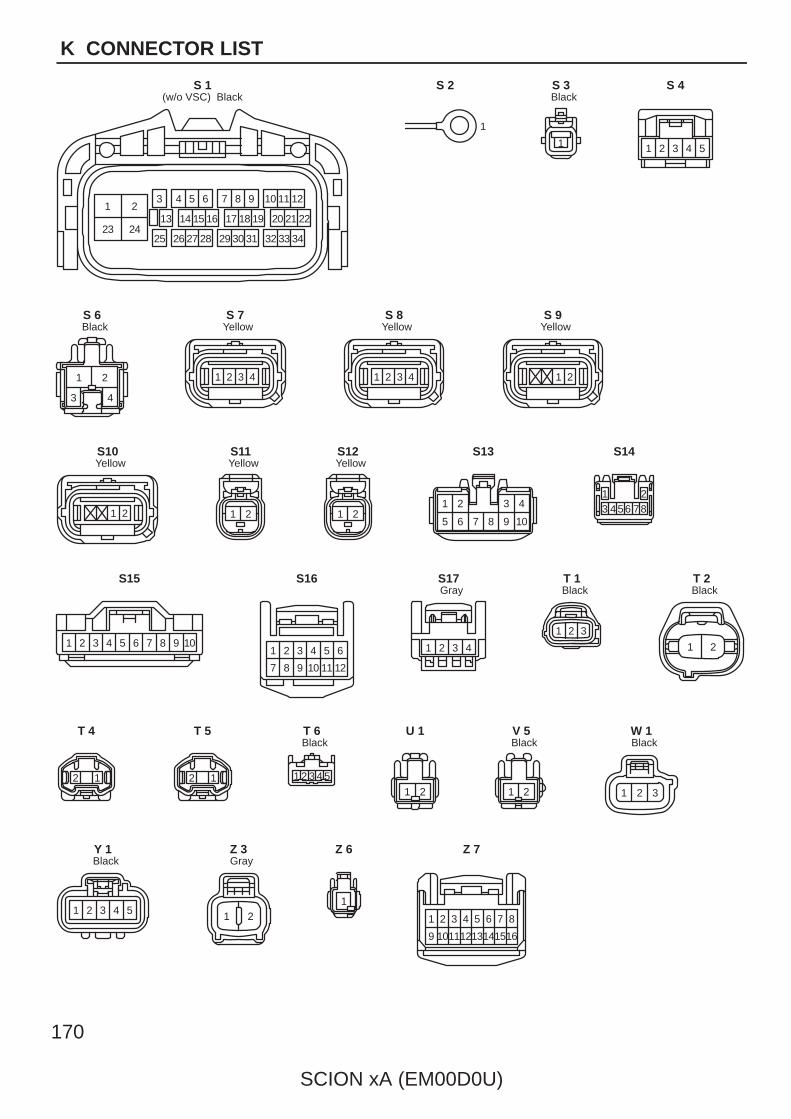
170
SCION xA (EM00D0U)
K CONNECTOR LIST
21
2423
3 4 5 6
13
25
161514
26 27 28 313029
17 18 19
987 10 11 12
222120
32 33 34
(w/o VSC) BlackS 1
1
S 2
1
BlackS 3
54321
S 4
1
3
2
4
BlackS 6
1 2 3 4
YellowS 7
1 2 3 4
YellowS 8
21
YellowS 9
21
YellowS10
1 2
YellowS11
1 2
YellowS12
1 2
5
3 4
6 7 8 9 10
S13
1 23 4 56 78
S14
10987654321
S15
7 8
1 2
12
4 5 6
9 1110
3
S16
1 2 3 4
GrayS17
1 2 3
BlackT 1
1 2
BlackT 2
12
T 4
12
T 5
1 2 3 4 5
BlackT 6
1 2
U 1
1 2
BlackV 5
1 2 3
BlackW 1
54321
BlackY 1
1 2
GrayZ 3
1
Z 6
9
1 2 3
16
4 5 86 7
1011 15141213
Z 7
SCION xA (EM00D0U)
171
Memo
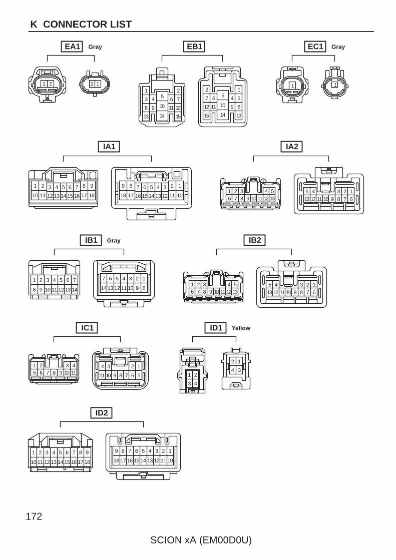
172
SCION xA (EM00D0U)
K CONNECTOR LIST
1 2 121 2
3 4
8 9
13
5
10
14
6 7
11 12
15
1
34
89
13
5
10
14
2
67
1112
15
1 1
1 2 3 4 5 6 7 8 9
10 11 12 13 14 15 16 17 18
9 8 7 6 5 4 3 2 1
18 17 16 15 14 13 12 11 101 2 3 4 56 7 8 9 10 11 12 13
1234513 6789101112
7
1413
65
1211
43
109
21
8
7
14
6
13
5
12
4
11
3
10
2
9
1
81 2 3 4 56 7 8 9 10 11 12 13
1234513 6789101112
1 2 3 45 6 7 8 9 10 11 11
4 3 2 1
5678910
2 1
4 31 2
3 4
9
18
8
1716
76
1514
54
1312
32
11
1
10
89
18 17
7
16
6
15
5
14
4
13
3
12
2
11
1
10
EA1 Gray EB1 EC1 Gray
IA1 IA2
IB1 Gray IB2
IC1 ID1 Yellow
ID2

SCION xA (EM00D0U)
173
K
4
9
53 6 7
13 1412 15 16
82
18
1
171110 7 6 5 4 3
15 1416 13 12
1289
10111718
123456
1 2
3 4 5 6
7
1413
65
1211
43
109
21
8
7
14
6
13
5
12
4
11
3
10
2
9
1
8
1 2 3 4 5 6 7 8 9 10
11 1213141516171819 20
12345678910
11121314151617181920
1 2
3 4 5 6123456 7
1413
65
1211
43
109
21
8
7
14
6
13
5
12
4
11
3
10
2
9
1
8
1 2 3 4 56 7 8 9 10 11 12 13
12345
13 6789101112 1 2 3 4 56 7 8 9 10
5 4 3 2 110 9 8 7 6
ID3 Blue IE1
IF1 IF2
IG1 IH1
IH2 BA1
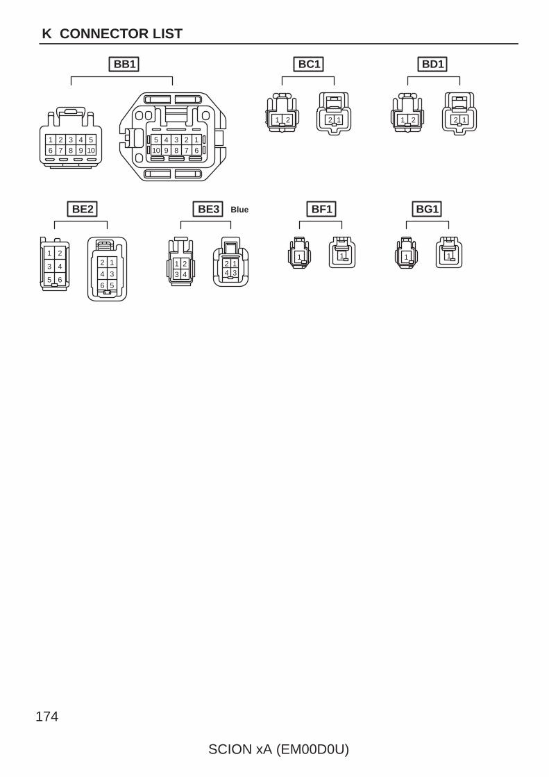
174
SCION xA (EM00D0U)
K CONNECTOR LIST
1 2 3 4 56 7 8 9 10
5 4 3 2 110 9 8 7 6
1 2 12 1 2 12
1 2
3 4
5 6
12
34
56
2
3 4
1 124 3
1 1 1 1
BE3 Blue
BB1 BC1 BD1
BE2 BF1 BG1

SCION xA (EM00D0U)
175
Memo
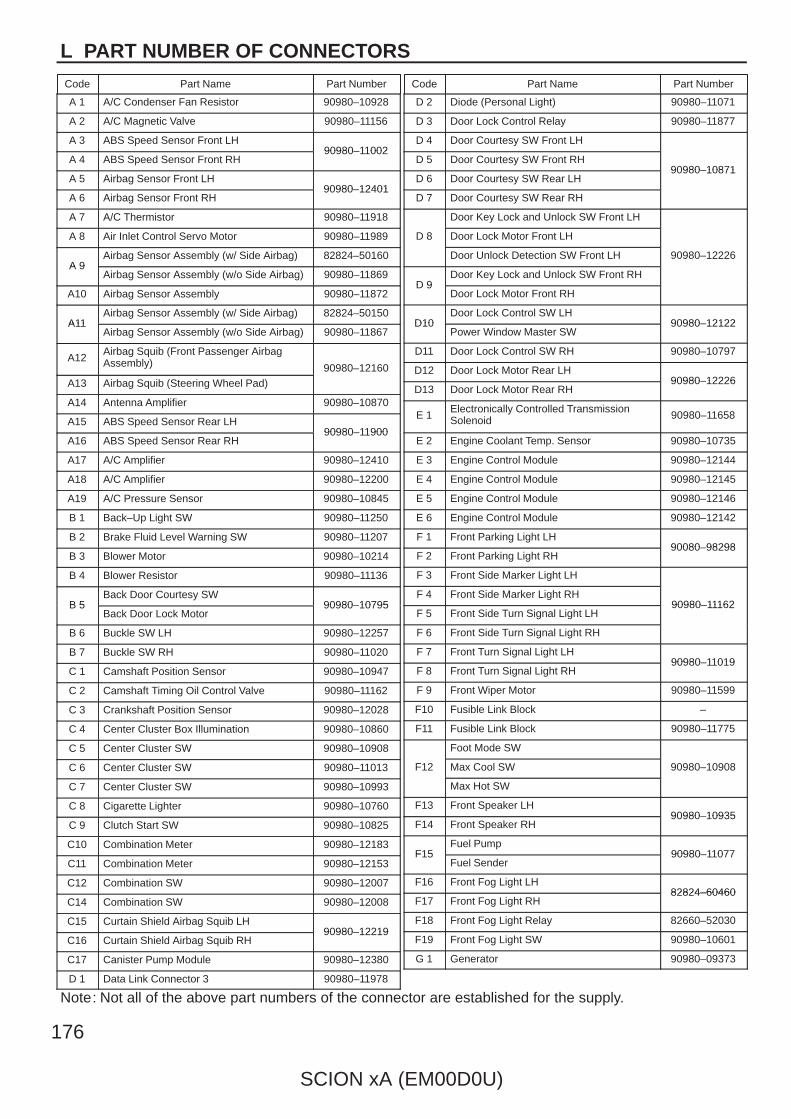
L PART NUMBER OF CONNECTORS
Code Part Name Part Number Code Part Name Part Number
SCION xA (EM00D0U)
Note: Not all of the above part numbers of the connector are established for the supply.
176
A 1 A/C Condenser Fan Resistor 90980–10928
A 2 A/C Magnetic Valve 90980–11156
A 3 ABS Speed Sensor Front LH90980–11002
A 4 ABS Speed Sensor Front RH90980–11002
A 5 Airbag Sensor Front LH90980–12401
A 6 Airbag Sensor Front RH90980–12401
A 7 A/C Thermistor 90980–11918
A 8 Air Inlet Control Servo Motor 90980–11989
A 9Airbag Sensor Assembly (w/ Side Airbag) 82824–50160
A 9Airbag Sensor Assembly (w/o Side Airbag) 90980–11869
A10 Airbag Sensor Assembly 90980–11872
A11Airbag Sensor Assembly (w/ Side Airbag) 82824–50150
A11Airbag Sensor Assembly (w/o Side Airbag) 90980–11867
A12Airbag Squib (Front Passenger AirbagAssembly) 90980–12160
A13 Airbag Squib (Steering Wheel Pad)90980–12160
A14 Antenna Amplifier 90980–10870
A15 ABS Speed Sensor Rear LH90980–11900
A16 ABS Speed Sensor Rear RH90980–11900
A17 A/C Amplifier 90980–12410
A18 A/C Amplifier 90980–12200
A19 A/C Pressure Sensor 90980–10845
B 1 Back–Up Light SW 90980–11250
B 2 Brake Fluid Level Warning SW 90980–11207
B 3 Blower Motor 90980–10214
B 4 Blower Resistor 90980–11136
B 5Back Door Courtesy SW
90980–10795B 5Back Door Lock Motor
90980–10795
B 6 Buckle SW LH 90980–12257
B 7 Buckle SW RH 90980–11020
C 1 Camshaft Position Sensor 90980–10947
C 2 Camshaft Timing Oil Control Valve 90980–11162
C 3 Crankshaft Position Sensor 90980–12028
C 4 Center Cluster Box Illumination 90980–10860
C 5 Center Cluster SW 90980–10908
C 6 Center Cluster SW 90980–11013
C 7 Center Cluster SW 90980–10993
C 8 Cigarette Lighter 90980–10760
C 9 Clutch Start SW 90980–10825
C10 Combination Meter 90980–12183
C11 Combination Meter 90980–12153
C12 Combination SW 90980–12007
C14 Combination SW 90980–12008
C15 Curtain Shield Airbag Squib LH90980–12219
C16 Curtain Shield Airbag Squib RH90980–12219
C17 Canister Pump Module 90980–12380
D 1 Data Link Connector 3 90980–11978
D 2 Diode (Personal Light) 90980–11071
D 3 Door Lock Control Relay 90980–11877
D 4 Door Courtesy SW Front LH
90980–10871D 5 Door Courtesy SW Front RH
90980–10871D 6 Door Courtesy SW Rear LH
90980–10871
D 7 Door Courtesy SW Rear RH
D 8
Door Key Lock and Unlock SW Front LH
90980–12226
D 8 Door Lock Motor Front LH
90980–12226Door Unlock Detection SW Front LH 90980–12226
D 9Door Key Lock and Unlock SW Front RH
D 9Door Lock Motor Front RH
D10Door Lock Control SW LH
90980–12122D10Power Window Master SW
90980–12122
D11 Door Lock Control SW RH 90980–10797
D12 Door Lock Motor Rear LH90980–12226
D13 Door Lock Motor Rear RH90980–12226
E 1Electronically Controlled TransmissionSolenoid 90980–11658
E 2 Engine Coolant Temp. Sensor 90980–10735
E 3 Engine Control Module 90980–12144
E 4 Engine Control Module 90980–12145
E 5 Engine Control Module 90980–12146
E 6 Engine Control Module 90980–12142
F 1 Front Parking Light LH90080–98298
F 2 Front Parking Light RH90080–98298
F 3 Front Side Marker Light LH
90980–11162F 4 Front Side Marker Light RH
90980–11162F 5 Front Side Turn Signal Light LH
90980–11162
F 6 Front Side Turn Signal Light RH
F 7 Front Turn Signal Light LH90980–11019
F 8 Front Turn Signal Light RH90980–11019
F 9 Front Wiper Motor 90980–11599
F10 Fusible Link Block –
F11 Fusible Link Block 90980–11775
F12
Foot Mode SW
90980–10908F12 Max Cool SW 90980–10908
Max Hot SW
F13 Front Speaker LH90980–10935
F14 Front Speaker RH90980–10935
F15Fuel Pump
90980–11077F15Fuel Sender
90980–11077
F16 Front Fog Light LH82824–60460
F17 Front Fog Light RH82824–60460
F18 Front Fog Light Relay 82660–52030
F19 Front Fog Light SW 90980–10601
G 1 Generator 90980–09373
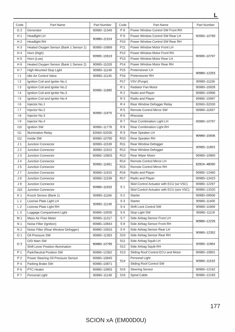
L
Code Part Name Part Number Code Part Name Part Number
SCION xA (EM00D0U)
177
G 2 Generator 90980–11349
H 1 Headlight LH90980–11314
H 2 Headlight RH90980–11314
H 3 Heated Oxygen Sensor (Bank 1 Sensor 1) 90980–10869
H 4 Horn (High)90980–10619
H 5 Horn (Low)90980–10619
H 6 Heated Oxygen Sensor (Bank 1 Sensor 2) 90980–11028
H 7 High Mounted Stop Light 90980–11148
I 1 Idle Air Control Valve 90980–11145
I 2 Ignition Coil and Igniter No.1
90980–11885I 3 Ignition Coil and Igniter No.2
90980–11885I 4 Ignition Coil and Igniter No.3
90980–11885
I 5 Ignition Coil and Igniter No.4
I 6 Injector No.1
90980–11875I 7 Injector No.2
90980–11875I 8 Injector No.3
90980–11875
I 9 Injector No.4
I10 Ignition SW 90980–11778
I11 Illumination Relay 82660–52030
I12 Inside SW 90980–10795
J 1 Junction Connector 90980–11539
J 2 Junction Connector 90980–11915
J 3 Junction Connector 90980–10803
J 4 Junction Connector90980–11661
J 5 Junction Connector90980–11661
J 7 Junction Connector 90980–11915
J 8 Junction Connector 90980–11539
J 9 Junction Connector90980–11915
J10 Junction Connector90980–11915
K 1 Knock Sensor (Bank 1) 90980–11166
L 1 License Plate Light LH90980–11148
L 2 License Plate Light RH90980–11148
L 3 Luggage Compartment Light 90980–10935
M 1 Mass Air Flow Meter 90980–11317
N 1 Noise Filter (Ignition) 90980–10843
N 2 Noise Filter (Rear Window Defogger) 90980–10916
O 1 Oil Pressure SW 90980–11363
O 2O/D Main SW
90980–10795O 2Shift Lever Position Illumination
90980–10795
P 1 Park/Neutral Position SW 90980–12362
P 2 Power Steering Oil Pressure Sensor 90980–10845
P 4 Parking Brake SW 90980–10871
P 6 PTC Heater 90980–10903
P 7 Personal Light 90980–11148
P 8 Power Window Control SW Front RH
90980–10789P 9 Power Window Control SW Rear LH 90980–10789
P10 Power Window Control SW Rear RH
P11 Power Window Motor Front LH
90980–10797P12 Power Window Motor Front RH
90980–10797P13 Power Window Motor Rear LH
90980–10797
P14 Power Window Motor Rear RH
P15 Pretensioner LH90980–12253
P16 Pretensioner RH90980–12253
P17 VSV (Purge) 90980–11156
R 1 Radiator Fan Motor 90980–10928
R 2 Radio and Player 90980–10996
R 3 Radio and Player 90980–10997
R 4 Rear Window Defogger Relay 82660–52030
R 5 Remote Control Mirror SW 90980–11657
R 6 Rheostat
90980–10797R 7 Rear Combination Light LH 90980–10797
R 8 Rear Combination Light RH
R 9 Rear Speaker LH90980–10935
R10 Rear Speaker RH90980–10935
R11 Rear Window Defogger90980–11853
R12 Rear Window Defogger90980–11853
R13 Rear Wiper Motor 90980–10860
R14 Remote Control Mirror LH82824–48090
R15 Remote Control Mirror RH82824–48090
R16 Radio and Player 90980–12460
R17 Radio and Player 90980–12423
S 1Skid Control Actuator with ECU (w/ VSC) 90980–12297
S 1Skid Control Actuator with ECU (w/o VSC) 90980–12020
S 2 Starter 90980–09506
S 3 Starter 90980–11400
S 4 Shift Lock Control SW 90980–11909
S 6 Stop Light SW 90980–11118
S 7 Side Airbag Sensor Front LH90980–12225
S 8 Side Airbag Sensor Front RH90980–12225
S 9 Side Airbag Sensor Rear LH90980–12352
S10 Side Airbag Sensor Rear RH90980–12352
S11 Side Airbag Squib LH90980–11864
S12 Side Airbag Squib RH90980–11864
S13 Sliding Roof Control ECU and Motor 90980–10801
S14Personal Light
90980–11533S14Sliding Roof Control SW
90980–11533
S15 Steering Sensor 90980–12162
S16 Spiral Cable 90980–12183

L PART NUMBER OF CONNECTORS
Code Part Name Part Number Code Part Name Part Number
SCION xA (EM00D0U)
Note: Not all of the above part numbers of the connector are established for the supply.
178
S17 Stereo Jack Adapter 82824–21030
T 1 Throttle Position Sensor 90980–11261
T 2 Turbine Speed Sensor 90980–11156
T 4 Tweeter LH90980–11159
T 5 Tweeter RH90980–11159
T 6 TRAC Off SW 90980–10631
U 1 Unlock Warning SW 90980–10860
V 5 VSC Warning Buzzer 90980–10906
W 1 Washer Motor 90980–10981
Y 1 Yaw Rate Sensor 90980–11904
Z 3 Option Connector (TVIP Siren) 90980–11051
Z 6 Option Connector (TVIP ECU) 90980–10871
Z 7 Option Connector (IPOD Unit) 90980–12553
L
Code Part Name Part Number Code Part Name Part Number
SCION xA (EM00D0U)
179

SC
ION
xA (E
M00D
0U)
183 M
1 2 3 4
IF2 9 IF2
(w/o VSC)12
B
2
1 xA
A2A4
1
2
60A M
AIN
W–R
W–L
W–L
W–R
B
B–G
7 1A
1 1O
2
15A A
M2
120A A
LT
2
AM25 6
2AM1
ST2
IG2
IG1
ACC
1
1O8
1C1
2
1
2
30A S
T
50A A
M1
B1
B–R
B–Y
B
IG
M
A1
B2
B3
L
B1
1O4
1E5
11
1G9
1E10
6 1O 1G8
4 IF2
2
1
3
5
2 2
2
5 EB1
1 B1A
2
ED
EB1
1E6 1A3
1O7
11 EB1
EC Cylinder Head
1
B
W–B
W–B
B–Y
B–Y
B–R
B–R
G–R
B–R
G–B
B–R
G–O
B–R
G–Y
Y
W–B
W–B
W–B
Y Y
W–B
W–B
Y
B–R
B–R
B–W
YY
R–B
B
B
B–R B–R
B–R
Y Y
W W–B
B–R B–R B–R
B–W
B–W
B–R
R–B
L
L L
L
B–R
F10 (A ), F11 (B )
B
Battery
B–R
STRelay
4
(M/T )
(A/T )
(A/T )
P
N
1 3 1 3 1 3 1 3
4 2 4 2 4 2 4 2
C11
Engine ControlModule<2–9>
Engine Control Module<2–9>
I10
Engine C
ontrolM
odule<2–8>
A/C
Am
plifier<
20–4>
3 A
10A G
AU
GE
B–Y
4
5
1
P o w e r S o u rc e S ta r tin g a n d Ig n it io n C h a rg in g
13 IF2
Front FenderApron LH
2
1
(w/ VSC)
Y
B(A
/T )B
(A/T )
W–B
W–B
I 4I 3
B(A/T)
(M/T )
Engine ControlModule<2–8>
I 5
B(M/T)
15 EB1
32
Charge
13
I 2
N 1
C 9
P 1
G 1(A), G 2(B)S 2(A), S 3(B)
Clutch S
tart SW
Com
bination Meter
Fusible Link Block
Generator
Ignition Coil and
Igniter No. 1
Ignition Coil and
Igniter No. 2
Ignition Coil and
Igniter No. 3
Ignition Coil and
Igniter No. 4
Ignition SW
Noise Filter
(Ignition )
Park/N
eutralP
osition SW
Starter
+B IGT
GND IGF
+B IGT2
GND IGF
+B IGT3
GND IGF
+B IGT4
GND IGF
B–Y
1 EB1
11 IF1
B–Y
B–Y
(M/T)B–Y
B–Y Engine ControlModule<2–8>
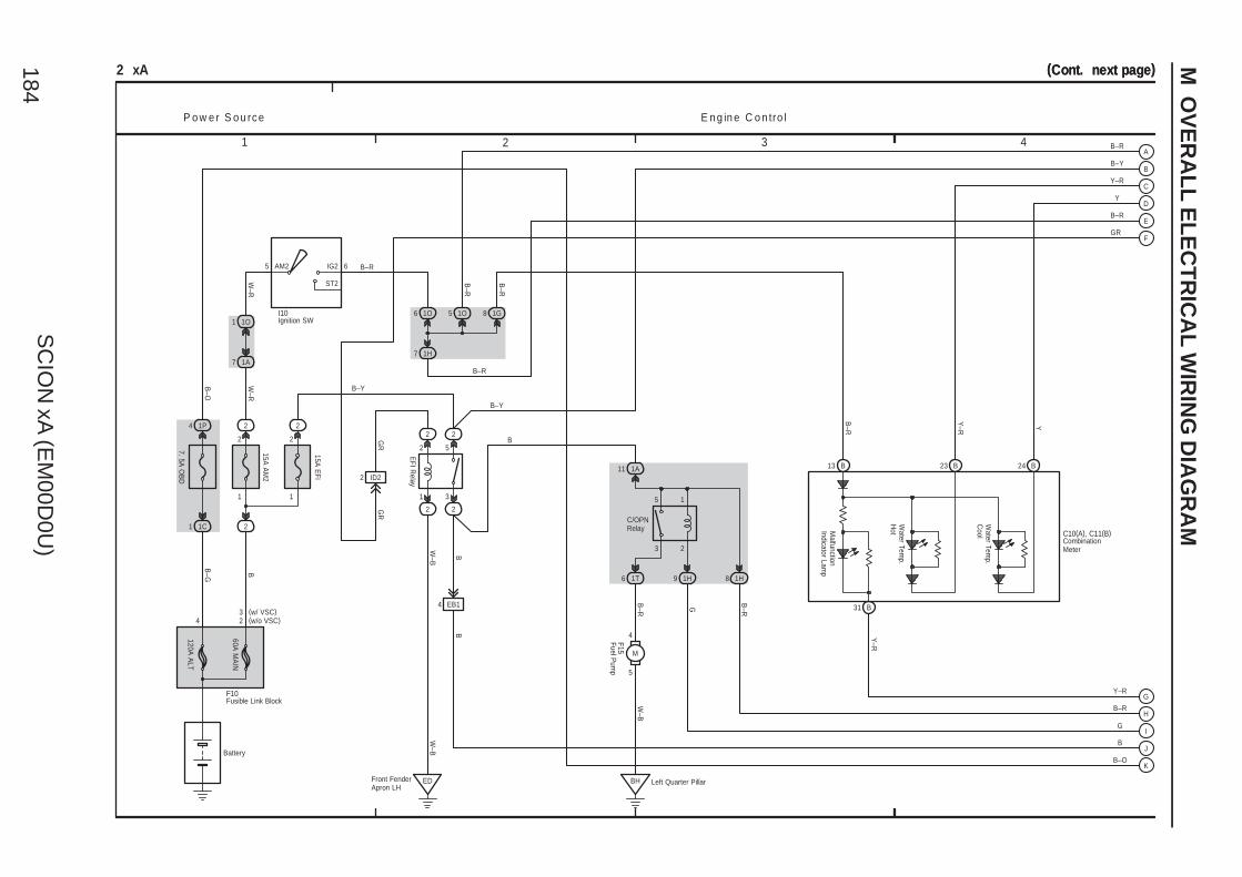
SC
ION
xA (E
M00D
0U)
184
M O
VE
RA
LL
EL
EC
TR
ICA
L W
IRIN
G D
IAG
RA
M
1 2 3 4
(Cont. next page)2 xA
1
2
60A M
AIN
4 2
W–R
W–R
B
B–G
7 1A
1 1O
2
15A A
M2
120A A
LT
2
AM25 6
ST2
IG2
1C1
P o w e r S o u rc e E n g in e C o n tro l
2
1 1
2
3
5
2
15A E
FI
2 2
2 2
1O6
1H7
EDFront FenderApron LH
11 1A
2
1
B24B23
5 1O
Left Quarter PillarBH
5
4
M
86 1T 9 1H 1H
EB14
4 1P
7. 5A O
BD
W–B
3W–B
B
B–Y
5
B31
B–R
B–R
Y
Y–R
B–Y
B–R
Y–R
B–R
G
B
B–O
B
W–B
B–R
G B–R
Y–R
Y–R Y
B–R
B–Y
B
EFI R
elay
C/OPNRelay
(Cont. next page)
B–OBattery
B–R
F15
Water Tem
p. C
ool C10(A), C11(B)
Water Tem
p. H
ot
B–R
1G8
13 B
Malfunction
Indicator Lamp
F10
3(w/o VSC)(w/ VSC)
I10
CombinationMeter
Fusible Link Block
Fuel Pum
p
Ignition SW
2 ID2
B–R
GR
GR
GR
A
B
C
D
E
F
G
H
I
J
K
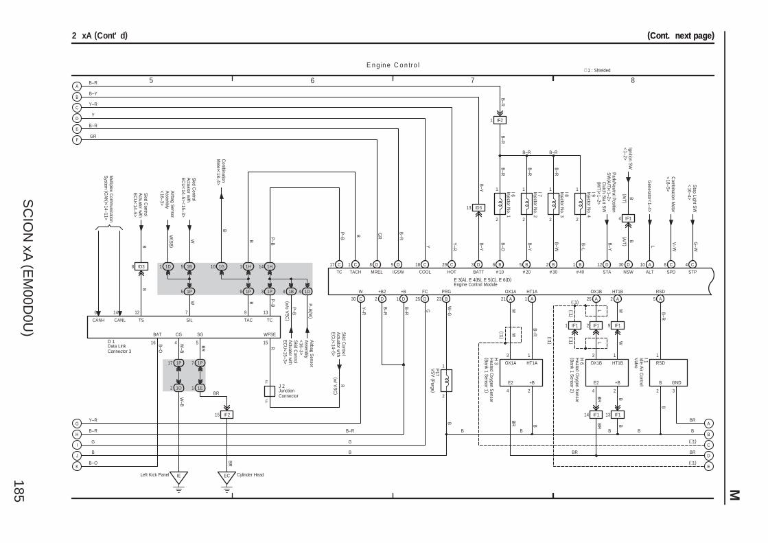
SC
ION
xA (E
M00D
0U)
185 M
7 865
(Cont. next page)
1H
SG
BR
BR
10 1G
P–B
D91
BR
BR
B
(∗1)
Airbag S
ensorA
ssembly
<16–3>
TCSIL
P–B
P–B
(W)
B–O
B–O
Skid C
ontrolA
ctuator with
EC
U<
15–3>
B
G
B–R
Y–R
W
BAT
16
Skid C
ontrolA
ctuator with
EC
U<
14–5><
15–3>
Airbag S
ensorA
ssembly
<16–3>
P–B
P–B
13
14 1H
3 1P
7
5 1P
CG
4
W–B
W–B
1P17
2 1O
5
C17
E n g in e C o n tro l
(A/T )
Park/N
eutral Position
SW
(A/T )<
1–2>B
–Y
D12
Ignition SW
<1–2>
B
D30
Generator<
1–4>L
A10
Com
bination Meter
<18–5>
V–W
C8
Stop Light S
W<
10–4>G
–W
(Cont. next page)
C4(∗1 )
B B B
11313
322424
B–R
B
B–R
WL
B–R
B–R
B–R
B–R
B–R
B–Y
Y Y–R
B–Y
B–O
B–Y
B–W
B–L
Y–R
B–R
G
W–G
B
BR
BR
1B
W
13
BB
B
BR
4
(∗1 )
B–RB–R
B–R
B–Y
Y–R
Y
B–R
B
G
B–R
30 C
1D4
WFSE
A1 A5A2A25A21B23
1
2
D25D1
C18 C29 D3
ID313
B1B2B5B6
1
2
1
2
1
22
1
IF21
2 xA (Cont' d)
1P7
1 1E
EC Cylinder HeadLeft Kick Panel IE
1 C
15
B
B
B14 IF1
2 IF1
BR
L W
IF1
B
(∗1 )
1B51D1
W
W(S
B)
OX1A HT1A
E2 +B
OX1B HT1B
E2 +B
RSD
B GND
TC TACH IGSW COOL HOT BATT
W +B FC PRG OX1A HT1A OX1B HT1B RSD
# 10 # 20 # 30 # 40 STA NSW ALT SPD STP
∗ 1 : Shielded
W
R
Com
binationM
eter<18–4>
15 IF2
BR
D 1
CANH
6
CANL
14
Skid C
ontrolA
ctuator with
EC
U<
14–5>
F R
Clutch S
tart SW
(M/T )<
1–2>
E 3(A), E 4(B), E 5(C), E 6(D)
1 IF1
(∗1)
(∗1 )
(∗1)
P17
H 3
H 6
I 1
(w/ V
SC
)
I 9I 8I 7I 6
Data LinkConnector 3
Engine Control Module
Heated O
xygen Sensor
(Bank 1 S
ensor 1 )
Heated O
xygen Sensor
(Bank 1 S
ensor 2 )
Idle Air C
ontrolV
alve
Injector No. 1
Injector No. 2
Injector No. 3
Injector No. 4
VS
V (P
urge )
(w/o V
SC
)
8 D
MREL
B–R
1P9
B
TAC
9
J 2JunctionConnector
F
2 D
B–R
+B2
4 IF1
B(A
/T )
GR
9 IF1
GR
ID3
B
8
Skid C
ontrolA
ctuator with
EC
U<
14–5>
B
Multiplex C
omm
unicationS
ystem (C
AN
)<14–11>
TS
12
A
B
C
D
E
F
G
H
I
J
K
A
B
C
D
E
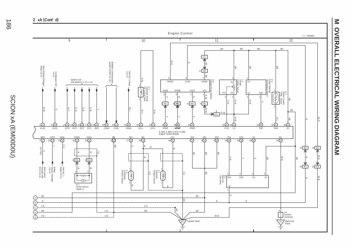
SC
ION
xA (E
M00D
0U)
186
M O
VE
RA
LL
EL
EC
TR
ICA
L W
IRIN
G D
IAG
RA
M
9 10 11 12
R–W
2
BR
BR
BR
P
R–W
(∗1 )
R–W
P
48
IB11
C
IF1
Com
bination SW
<6–3>
G
2 xA (Cont' d)
30B29 B 28 B
2
1
26 A
EC Cylinder Head
6 A 4 B7 A
28 A20 A 18 A 32 B 32 A
7
IB112
5 D
BR BR BR
BR
Y–B V P BR
BR
BR
BR
BR
BY
–R
R–W
R–W
R–L
BR
BR
BR
9
B
∗ 1 : Shielded
BR
(∗1)
1
3 1 3 2
B
4 2 3 5
2 1
BR
(∗1 )
W
BR
W–L
2
1
13 A 12 A
R–Y
R–B
R–B
FAN
NO
. 2 Relay
<19–2>
D14
Ignition Coiland Igniters<1–3><1–4>
BR
B
E n g in e C o n tro l
A23A17
G–Y
G–O
A16
G–B
A15
G–R
Y
A1415 D
VC PSP
E2
22 D
W–B
BR
W–B
IB1
BR
THA E2G VG E2
+B
ELS1 IGT4 IGT3 IGT2 IGT1 IGF1 FANH OC1+ OC1– VPMP
G2+ E01 E02 E03 THA EZG VG EC
VTA1 VC PSP THW E2
BR
R–W Y
32
BR
BR
W
EA1
W(∗1)
(∗1 )
W
WOBR
1
3 A A34A27
1
2
29 A
E1KNK1 NE+ NE–F/PS
D13
FANL E1
Y–RY
FAN
NO
. 1R
elay<19–2>
Airbag
Sensor A
ssembly
<16–4>
IF18
BR
C 2
C17
T 1
P 2
E 2
M 1
C 1
C 3
(∗1)
C7
NEO
V
E 3(A), E 4(B), E 5(C), E 6(D)
C3
ELS2
Cam
shaftP
osition Sensor
Crankshaft
Position S
ensor
Cam
shaft Timing
Oil C
ontrol Valve
Engine C
oolantTem
p. Sensor
Engine Control Module
Mass A
irFlow
Meter
Pow
er Steering
Oil P
ressure Sensor
ThrottleP
osition Sensor
Canister P
ump M
odule
(w/ V
SC
)
VTA VC
E2
VCC
SGND
Skid C
ontrolA
ctuator with
EC
U<
14–4>
Rear W
indow D
efoggerR
elay<19–4>
B–W
C34C33
CANH CANL
Multiplex C
omm
unicationS
ystem (C
AN
)<14–10>
B
EA12
Knock Sensor(Bank 1)
K 1
30 A
EKNK
WB
IG Right KickPanel
A
JunctionConnector
J 8
14 IB1 13 IB1
20 IF2 10 IF2
B
W–B
B
W–B
W–B
B
W–B
B
B B
VLVBMGND
96
2
1
VV
1
IB18
5 D
VPMPMPMP
D6
IB1
1
V RR
3
IB110
31 D
PPMP
VOUTMTRBVGND
1 2
(∗1)
(∗1)
A
B
C
D
E
SCION xA (EM00D0U)187
Memo
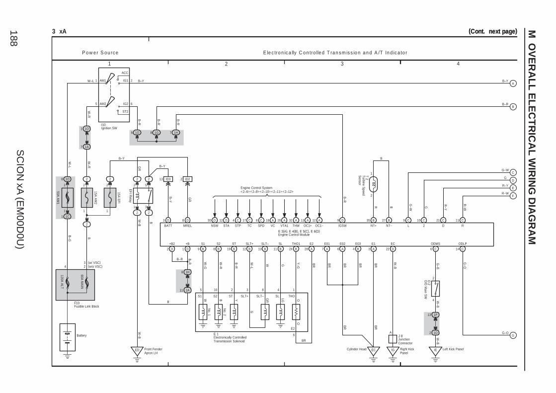
SC
ION
xA (E
M00D
0U)
188
M O
VE
RA
LL
EL
EC
TR
ICA
L W
IRIN
G D
IAG
RA
M
1 2 3 4
(Cont. next page)(Cont. next page)
T 2
O 2
E 1
E 3(A), E 4(B), E 5(C), E 6(D)
OC1–OC1+
A12A13
C14C
C17
A
4 C
3 xA
1
2
60A M
AIN
4 2
W–R
W–L
W–L
W–R
B
B–G
7 1A
1 1O
2
15A A
M2
120A A
LT
2
AM25 6
2AM1
ST2
IG2
IG1
ACC
1
1O8
1C1
P o w e r S o u rc e E le c tro n ic a lly C o n tro lle d T ra n s m is s io n a n d A /T In d ic a to r
2
11
2
3
5
2
15A E
FI
2 2
2 2
1O6
ED Front FenderApron LH
1H8
1A11
1 D 9 B B8 19 B 12 B B13 11 B 24 B
3 D
A28
13 ID3
35 B B27
2
1
7 A 6 A 4 B
ECCylinder Head
6
50A A
M1
4
2
IE Left Kick Panel
1P13
1O2
9 C 21 C 11 C10 C
W–G
W–R
B–R
W–L
W G Y–G
BR
BR
BR
BR
BR
BR
W–B
W–B
W–B
B–Y
W–B
B
B–R
R B
B–R
GR
BR
BB–Y
B
B–Y
5 10 2 3 8 4 1
6
18 A 20 A 32 A
B–Y
EFI R
elay
G–B
2
22
W–B
1
8C
S1 S2 ST SLT+ SLT– SL THOW B Y
G
LG OO
GR
E2
BR
D3
+B S1 S2 ST SLT+ SLT– SL THO1 E2
BATT STP TC SPD VC VTA1 THW NT+ NT– L 2 D R
E01 E02 E03 E1 EC ODMS
Battery
1G8
F10
3(w/o VSC)(w/ VSC)
I10
G–W
G
R–Y
R–W
G–O
B–Y
G–W G R–Y
R–W
G–O
ODLP
B–R
B–R
Electronically ControlledTransmission Solenoid
Engine Control Module
Fusible Link Block
Ignition SWO
/D M
ain SW
Turbine Speed
Sensor
No. 1
No. 2
Engine Control System<2–6><2–8><2–10><2–11><2–12>
12 D
STA
30 D
NSW
D8
MREL
2 ID2
GR
1H7
B–R
D9
IGSW
B–R
IG Right KickPanel
J 8JunctionConnector
A
2 D
+B2
B–R
A
B
C
D
E
F
G
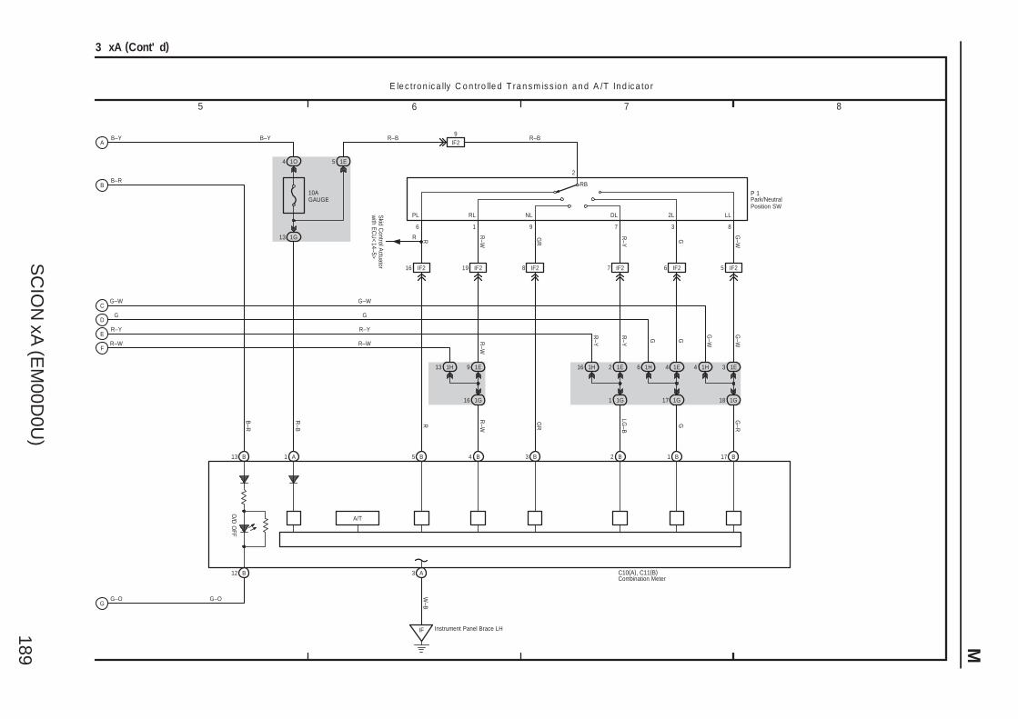
SC
ION
xA (E
M00D
0U)
189 M
7 865
3 xA (Cont' d)
Instrument Panel Brace LHIF
A3B12
B171 BB2B3B4B5A1
9IF2
5 1E
1G13
4 1O
10AGAUGE
16 IF2 19 IF2 8 IF2 7 IF2 6 IF2 5 IF2
1E4 1E31E21E91H13 1H16 1H6 1H4
1G1817 1G1G11G16
G–O
R–W
R–Y
G
G–W
B–R
13 B
R–WRR–B
B–R
GR
LG–B
G G–R
G–W
G–WGGR–Y
R–YR
–WR–W
R–Y
G
G–W
R
R–W
GR
R–Y
G
G–W
R–BR–BB–Y
W–B
G–O
C10(A), C11(B)
P 1
E le c tro n ic a lly C o n tro lle d T ra n s m is s io n a n d A /T In d ic a to r
Combination Meter
Park/NeutralPosition SW
R
Skid C
ontrol Actuator
with E
CU
<14–5>
O/D
OFF
A/T
B–Y
6 1 9 7 3 8
2
PL RL NL DL 2L LL
RB
A
B
C
D
E
F
G
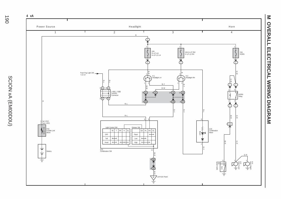
SC
ION
xA (E
M00D
0U)
190
M O
VE
RA
LL
EL
EC
TR
ICA
L W
IRIN
G D
IAG
RA
M
1 2 3 4
4 xA
2
60A M
AIN
OFF
Tail
Head
+B T RF H EL
Flash
Low
High
ED HL HU EL
6 1M
2 1O
2
10AH–LP LH/H–LP LO LH
2
10A H–LP RH/H–LP LO RH
2
1 2
3
1 2
3
1A9
7 1M
1A8 1B10 1B11
5 1M 1F2
B A
B B B B
8 9
R–Y
B
W–B
B–YB
–W
R–Y
R–Y
B
R–L
R–L
Front Fog Light SW<13–2>
B–Y
B–W
B–R B
1 1
2 2
11
P o w e r S o u rc e H e a d lig h t
Battery
R–L
Light Control SW Dimmer SW
AB
R–L
R–L
Beam
C10
(w/o VSC)(w/ VSC)3
F10
C12
J 4(A), J 5(B)
H 1 H 2
IE Left Kick Panel
W–B
8
2
CombinationMeter
Combination SW
Fusible LinkBlock
Headlight LH Headlight RH
JunctionConnector
2
1
3
5
22
HORNRelay
22
W–R
4 ID3
G–R
G–R
1
W–R
1H 5
H 4
G–R
G–W
Horn (Low
)
Horn (H
igh )
15AHORN
2
G–W
1
2
H o rn
6
Horn
S16S
piral Cable
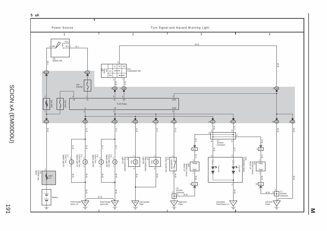
SC
ION
xA (E
M00D
0U)
191 M
1 2 3 4
5
5 xA
120AALT
4
1C1
B–G
50A A
M1
10A H
AZ
1O8
Battery
1N
2 1M
4 1O
1
ACC
IG1AM1 2
10AGAUGE
1M3 1M1
1
5 6
7
LH
RH
6
G–Y
G–B
1B7 1B6
G–B
ED
W–B
EA
G–Y
W–B
3 2
1F14 1F9
P–B
G–Y W
–BW
–B
W–B
FLSH Relay
4 1
+B IG EL ER
LL LR
W–L
B–Y
P o w e r S o u rc e T u rn S ig n a l a n d H a z a rd W a rn in g L ig h t
2 7
GND
TL TB TR
IE
5
W–B
F10
I10
C12
TurnS
ignalS
W
1 1
2 2
1
2
1
2
W–B
W–B
G–Y
G–Y
G–B
G–B
W–B
W–B
F 7
F 5
F 8
F 6 4
W–B
IF
C10
10
Com
bination Meter
Combination SW
Fusible LinkB
lock
Front TurnS
ignal Light LH
Front TurnS
ignal Light RH
Front Side Turn
Signal Light LH
Front Side Turn
Signal Light R
H
Ignition SW
InstrumentPanel Brace LH
Turn LH
Turn RH
3
A
1O2
W–B
W–B
JunctionConnector
J 1
Front FenderApron LH
Front FenderApron RH
TRNR
GND
2
1
1 IH1
G–Y
P–B
W–B
G–Y
G–Y
Rem
ote Control
Mirror LH
R15
14 IH1
Left KickPanel
A
A D
A D
DA
JunctionConnector
J 2
8
1J4
EHW
2
1
IG
G–O
A
W–B
Hazard S
W
C 6
Center C
luster SW
A
Turn
6
1
6
1
1S8 1T5
G–B
G–Y
BH
W–B
W–B
Turn
R 7
R 8
Rear C
ombination
Light LH
Rear C
ombination
Light RH
W–B
Left QuarterPillar
Right KickPanel
R14
Rem
ote Control
Mirror LH
TRNL
GND
IA11
2
1
16 IA1
W–B
P–B
P–B
JunctionConnector
J 8
W–B
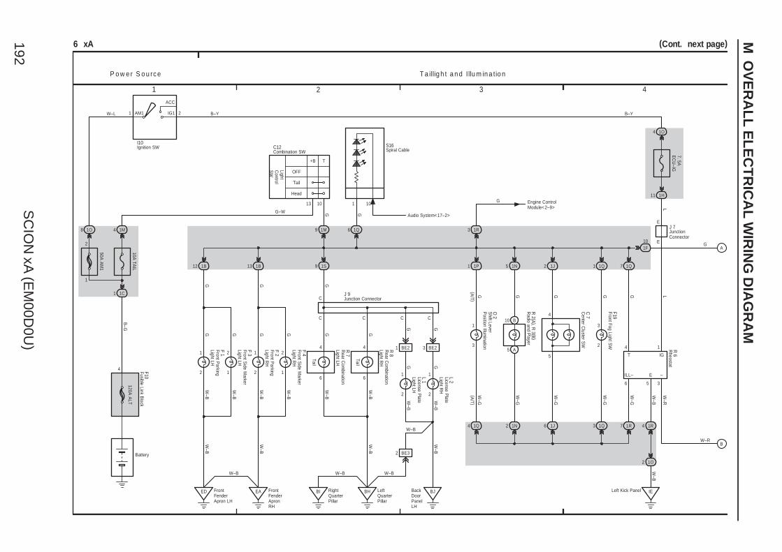
SC
ION
xA (E
M00D
0U)
192
M O
VE
RA
LL
EL
EC
TR
ICA
L W
IRIN
G D
IAG
RA
M
1 2 3 4
2
5
C
1A
1
W–G
6
B10
6 xA
Battery
4
120A A
LTB
–G
1M4
10A TA
IL
1C1
1B12 1B13 1S9
ED BH
6
GW
–B
GW
–B
G
GG
W–B
7
5
1R
W–B
3
1
5
4
1O2
4 1R
IE
1P1 1N5 1J2
G G G
2 1N
W–B
W–G
W–G
P o w e r S o u rc e T a illig h t a n d Illu m in a tio n
1J
1M9
W–B
(A/T )
O 2
R 2 (A ), R
3 (B )
2
C C
6
4
6
4
EA FrontFenderApronRH
OFF
Tail
Head
+B T
10
GG–W
C 7
W–G
1
(A/T )
1Q4
2
W–B
G
BackDoorPanelLH
C
1
2
W–B
G
C
BI RightQuarterPillar
BJ
W–B
F10
LightC
ontrolS
W
1
2
1
2
W–B
W–B
W–B
W–B
GGGG
F 1
F 3
F 2
F 4
R 7
R 8
Tail
W–B
W–B
J 9
W–B
LeftQuarterPillar
W–B
L 1
L 2
1 BE2 3 BE2
G G
3
2
3
1Q1
GW
–G
1Q
F19
Left Kick Panel
R 6
3
W–R
4
1Q7
G
101F
1O8
50A A
M1
1
ACC
IG1AM1 2W–L
I10
1O4
7. 5AE
CU
–IG
1H11
B–Y
1
L
E
E
L
J 7
B–Y
2
1
Center C
luster SW
13
Fusible Link Block
Front Parking
Light LH
Front Parking
Light RH
Front Side M
arkerLight LH
Front Side M
arkerLight R
H
Ignition SW
JunctionConnector
Junction Connector
License Plate
Light LH
License Plate
Light RH
Shift Lever
Position Illum
ination
Radio and P
layer
Rheostat
Rear C
ombination
Light LH
Rear C
ombination
Light RH
Front Fog Light SW
ILL– E –
IGT
Combination SWC12
W–B
BE32
FrontFenderApron LH
Tail
1R3
G Engine ControlModule<2–9>
G
W–R
(Cont. next page)
S16Spiral Cable
1 10
1Q6
G
Audio System<17–2>
A
B
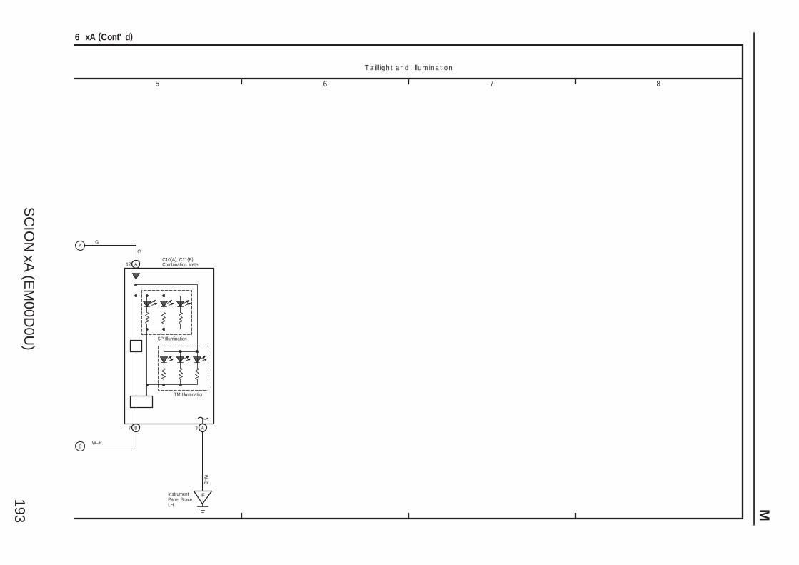
SC
ION
xA (E
M00D
0U)
193 M
7 865
6 xA (Cont' d)
G
12 A
7 B A3
W–B
IFInstrumentPanel BraceLH
SP Illumination
TM Illumination
C10(A), C11(B)Combination Meter
G
W–R
T a illig h t a n d Illu m in a tio n
A
B
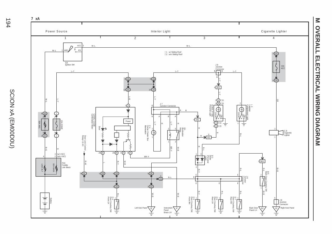
SC
ION
xA (E
M00D
0U)
194
M O
VE
RA
LL
EL
EC
TR
ICA
L W
IRIN
G D
IAG
RA
M
1 2 3 4
E
E
7 xA
4 1A
12 1G
1
2
60A M
AIN
5
W–L
W–L
B
B–G
2
15A D
OM
E
2
1S
AM1 IG1
ACC
1
1O8
1C1
50A A
M1
Battery
P o w e r S o u rc e In te r io r L ig h t
W–L3
1
2
4 2
1O3
15AACC
1N6
B
1S1
1G4
1
5 1G
1 1 1
2
1
GR
R–Y
R–L
R–L
L
R–Y
R–L
L–Y
L–B
L–Y L–Y
120A A
LT
E
C ig a re tte L ig h te r
IG Right Kick Panel
A
W–B
W–L
2
BB L–Y
A7
25 B
D 4
26 B
C10 (A ), C
11 (B )
F10
3(w/o VSC)(w/ VSC)
D 5
D 6
D 7
1
2
3
5
1
2
9 A
1K5
1O2
IELeft Kick Panel
C 4 I11
L–Y R L–Y RW
–B
BR
–Y
W–B
ABAB
1K10
B
L–Y
4 IB1
2
1
31S
ER–L
RA
L 3
ON
OFF
DO
OR
2 B (∗2)
2 A (∗1)
7 A (∗1)
1 B (∗2)
6 IE1
IE15
S14 (A ), P 7 (B )
L–YL–Y
J 9
E
2 BE2
R–L
R–L
1
E J 9
B 5
BJ
W–B
J 7
1L8
Door Lock C
ontrolR
elay<12–8>
R–W
I10
∗ 1 : w/ Sliding Roof∗ 2 : w/o Sliding Roof
C 8
J 8
BR–Y
Back D
oor Courtesy S
W
CigaretteLighter
Com
bination Meter
Center C
luster Box
Illumination
Door C
ourtesy SW
Front LH
Door C
ourtesy SW
Front RH
Door C
ourtesy SW
Rear LH
Door C
ourtesy SW
Rear R
H
FusibleLink Block
Ignition SW
LuggageC
ompartm
ent Light
JunctionConnector
Junction Connector
JunctionConnector
JunctionC
onnector
Illumination
Relay
Personal Light
3 A
Power
IFInstrumentPanelBrace LH
W–B
W–B
Door
1
2
DO
OR
OFF
ON
3 Diode
(Personal
Light )
D 2
R
R
R–L
R–Y
R
R
Back DoorPanel LH
R–L
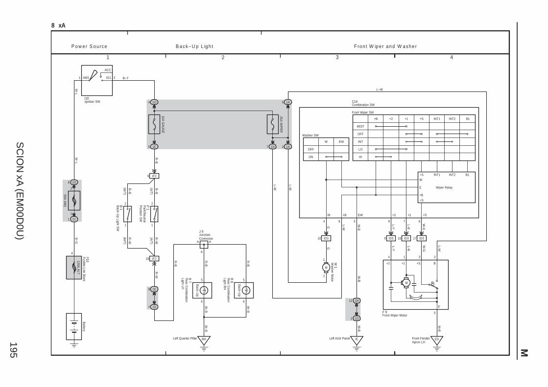
SC
ION
xA (E
M00D
0U)
195 M
1 2 3 4
2
1
A
8 xA
25A W
IPE
R
5 7 6
W–L
W–L
B–G
2AM1 IG1
ACC
1
1O8
1C1
50A A
M1
B–Y
Battery
P o w e r S o u rc e F ro n t W ip e r a n d W a s h e r
9 18 ID3
ED
A
L–W
W–G
L–B
L–Y
5
W–B
3 214
W–B
W–G
L–B
L–Y
W–B
M
B+1+2
E
11 1N
2 1O
4
ID310
Front FenderApron LH
17 ID3
9
1O
ID3
1
2
10A G
AU
GE
1E5
9 IF2
1E9
7 1S
BHLeft Quarter Pillar
R–W
R–W
R–B
R–B
R–B
W–B
W–B
R–B
R–B
L–W
B a c k – U p L ig h t
19
Left Kick Panel
A
6
5 5
6
M
1
2
IF2
IE
1N7 1A2
+S
1A5
L–WGG
L–W
L–W
84
OFF
ON
W EW
+S+1+2+B
INT
OFF
MIST
LO
HI
INT1 INT2 B1
Front Wiper SW
Washer SW
F 9
C14
W +B EW +2 +1 +S
+S INT1 INT2 B1
+S
W
E
+B
Wiper Relay
W–B
I10
2
1
(A/T )
(A/T )
R–W
R–B
(M/T )
(M/T )
B 1
P 1
Back–U
p
Back–U
p
W–B
R 8
R 7
J 9
W 1
Back–U
p Light SW
Combination SW
Front Wiper Motor
Ignition SW
JunctionConnector
Park/N
eutralP
osition SW
Rear C
ombination
Light LH
Rear C
ombination
Light RH
Washer M
otor
120A A
LT
4
Fusible Link Block
F10
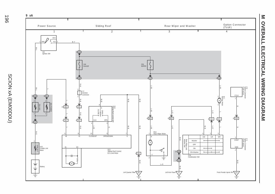
SC
ION
xA (E
M00D
0U)
196
M O
VE
RA
LL
EL
EC
TR
ICA
L W
IRIN
G D
IAG
RA
M
1 2 3 4
9 xA
1C1
50A A
M1
1O8
1
ACC
IG1AM1 2
B–G
B–Y
Battery
W–L
W–L
1
2
I10 1O4
10AGAUGE
30A P
OW
ER
1
2
1 IE1 2 IE1
7 IB1
C
C
1R8
3 IE1
BHLeft Quarter Pillar
25AWIPER
1T1 1A2
3
2
M
1 ID32 IB25 BE26 BE2
5 8 10 9 7
8
1 2 3
4 3
L
R–B
L–W
W–B
G
W–B
W–B
W–B
W–B
L–W
L–O
L–O LL
L–O
L–O
L–W
L–W
L–W
R–B
R–B
R–B
W–B
W–B
+B IG CLOSE/UP OPEN/DOWN E
W–B
S13
S14
W 1
J 2
EAFront Fender Apron RH
5 ID3
BB
W–B
2
1
1
GND
CTLS
CONT
Z 6Z 3
P o w e r S o u rc e S lid in g R o o f R e a r W ip e r a n d W a s h e r O p tio n C o n n e c to r(T V IP )
Ignition SW
JunctionConnector
Sliding Roof ControlECU and Motor
Sliding R
oof Control S
W
Washer M
otor
Option C
onnector(TV
IP S
iren )O
ption Connector
(TVIP
EC
U)
1L9
10 IB2
LL
L
11 1N
1O2
IELeft Kick Panel
5
W–B
M
–1 –
B
2
Rear Wiper MotorR13
L–O
OP
EN
CLO
SE
CLS OPN
E
Washer
ON
ON+Washer
EW +1R WR
OFF
Rear W
iper andW
asher SW
Combination SWC14
M
M– M+
120A A
LT
4
Fusible LinkBlock
F10

SC
ION
xA (E
M00D
0U)
197 M
1 2 3 4
Left Kick Panel
1
1P
C10(A), C11(B)
W–B
S 4
2
10 xA
W–L
W–L
B–G
120A A
LT
2AM1 IG1
ACC
1
1O8
1C1
Battery
P o w e r S o u rc e K e y R e m in d e r a n d S e a t B e lt W a rn in g S h ift L o c k
B–Y
4
50A A
M1
1O4
10AGAUGE
1G13
1F1
1P19
1 A
1
2
2 IB1 3 IB1
IG Right KickPanel
1P11
1P16 1O2
IE
Shift LockSolenoid
1
5 3
L–R B
W–B
G–W
R–B
SLS–SLS+E
IG STP
O
W–R
G–W
YY
W–B
W–B W
–B
W–B
R–B
R–B
1
2
10A S
TOP
1B
1
2
1B2
1T31P18
G–B
G–B
G–W
G–W
G–W
G–W
G–W
W–B
W–B
6 6
3 3
Stop
S to p L ig h t
7 A
15A D
OM
E
2
2
B
2
1
2
60A M
AIN
L–Y
9
15
1B1
G–W
Skid C
ontrolA
ctuator with
EC
U<
14–6><
15–3>
Taillight andIllum
ination System
<6–5>
L ig h t R e m in d e r
W–B
W–B
Instrument PanelBrace LH
IF
Interior Light System
<7–2>
Left QuarterPillar
BH
D
DD
W–B
1
6 A
L–B
U 1
6 B8 B 18 B3 A25 B12 A
1H2
G–W
Engine C
ontrolM
odule <2–8>
Passenger
O
D
Stop
C 7
Buckle S
W R
H<
16–8>
Buckle S
W LH
<16–8>
3(w/o VSC)(w/ VSC)
F10
BJBack DoorPanel LH
W–B
W–B
W–B
G–W
H 7
J 9
R 7
R 8
S 6
I10
W–R
Center C
luster SW
Combination Meter
Fusible Link Block
High M
ountedS
top Light
Ignition SW
Junction Connector
Rear C
ombination
Light LH
Rear C
ombination
Light RH
Shift Lock
Control S
W
Stop Light
SW
Unlock
Warning S
W
Power Buzzer
Driver
Seat B
elt
4 1A
1G12
3 BE3
2 BE3
8
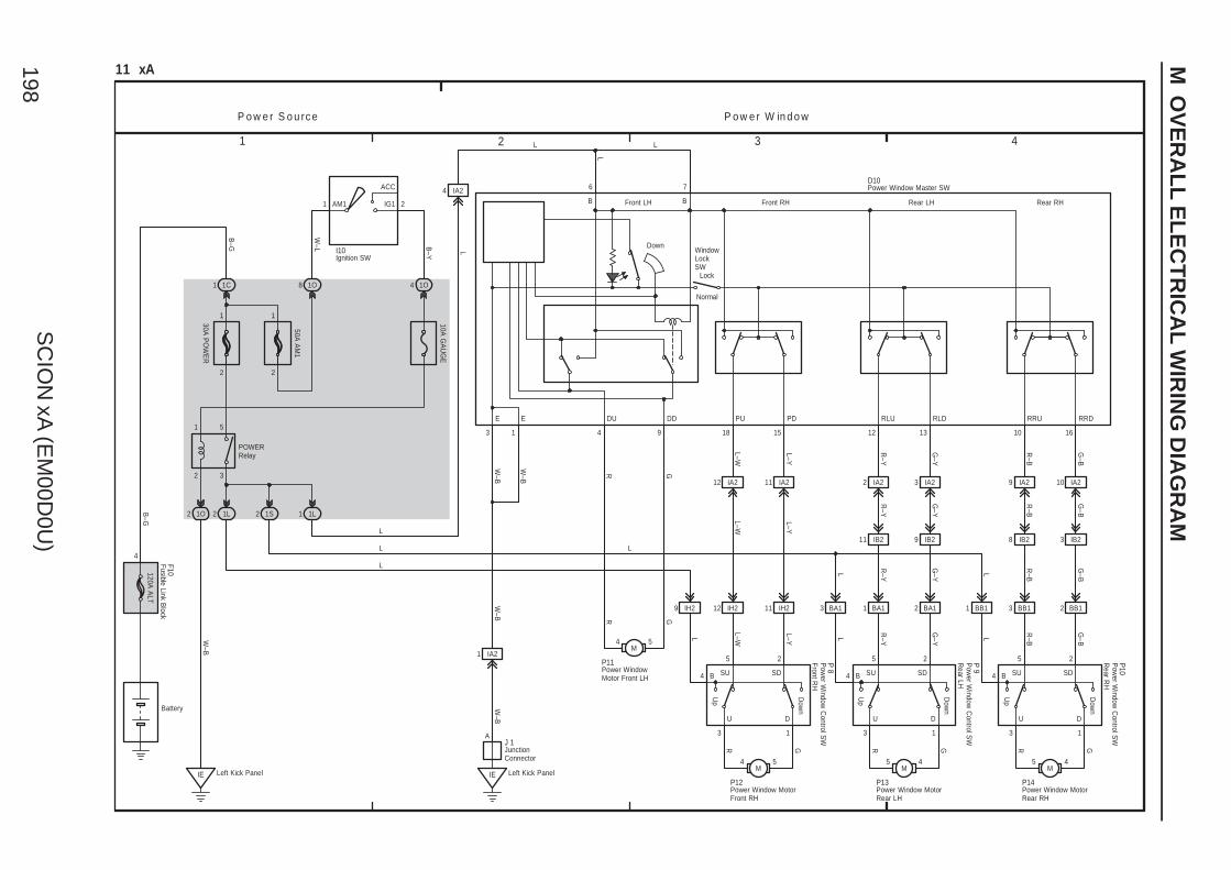
SC
ION
xA (E
M00D
0U)
198
M O
VE
RA
LL
EL
EC
TR
ICA
L W
IRIN
G D
IAG
RA
M
1 2 3 4
4 133
BA1BA1BA1
11 xA
P o w e r S o u rc e P o w e r W in d o w
2
1
3
5
1
ACC
IG1AM1 2
Left Kick PanelIE
1S1L 222 1O 1L1
1C1 1O8
L
W–B
4 IA2
9
2
1
M5 4
M5 4
M4 5
161018 1215
1
12 IA2 11 IA2 2 IA2 3 IA2 9 IA2 10 IA2
3 IB28 IB29 IB211 IB2
11 IH212 IH2
5 2 5 2 5 2
3 1 3 1 3 1
IH29
M4 5
A
Left Kick PanelIE
1O4
POWERRelay
Battery
PU PD RLU RLD RRU RRD
4 4 4
LL
L
L
L
L
B–G
B–G
W–L B
–Y L
G–B
R–B
G–Y
R–Y
L–Y
L–W
GR
G–B
R–B
G–Y
R–Y
L–Y
L–W
G–B
R–B
G–Y
R–Y
G–B
R–BL
G–Y
R–YLL–Y
L–WL
GR
W–B
W–B
GRGRGR
E E
1 IA2
W–B
L
DU DD
Down
30A P
OW
ER
50A A
M1
10A G
AU
GE
B BFront LH
WindowLockSW
Front RH Rear LH Rear RH
SU SD SU SD SU SDB B B
L
U
W–B
U U DDD
Up
Up
Dow
n
Dow
n
Up
Dow
n
22
1 1
3 1
D10
BB1
6 7
I10
3 BB1 2 BB1
P11
P12 P13 P14
P 8
P 9
P10
Ignition SW
Pow
er Window
Control S
WFront R
H
Pow
er Window
Control S
WR
ear LH
Pow
er Window
Control S
WR
ear RH
Power Window Master SW
Power WindowMotor Front LH
Power Window MotorFront RH
Power Window MotorRear LH
Power Window MotorRear RH
JunctionConnector
J 1
120A A
LT
4
Fusible Link Block
F10
Lock
Normal
SCION xA (EM00D0U)199
Memo
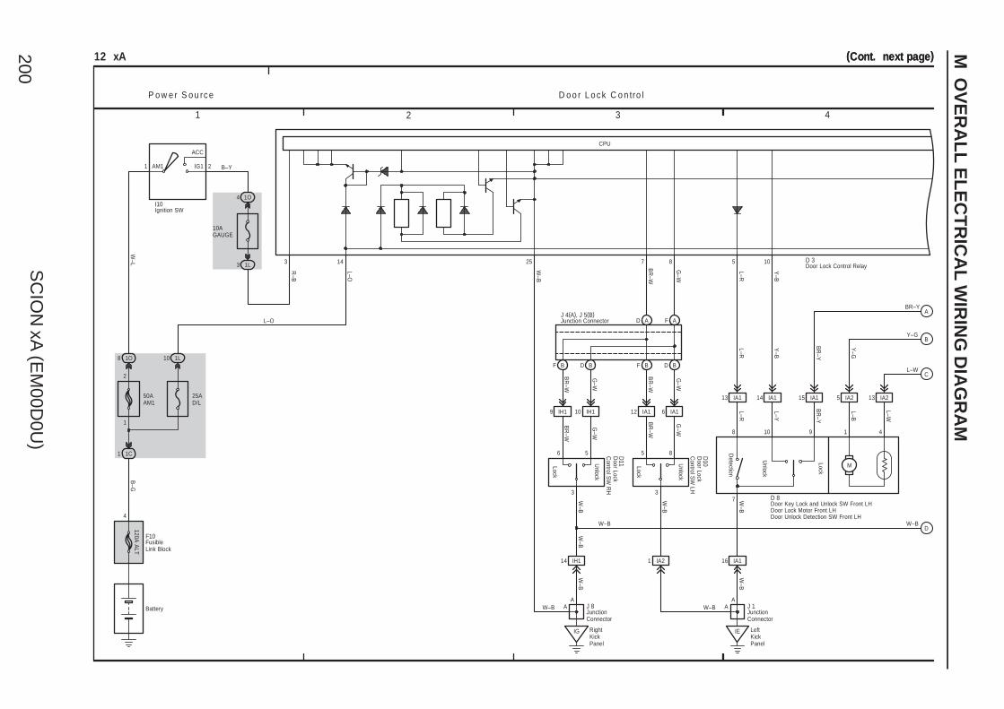
SC
ION
xA (E
M00D
0U)
200
M O
VE
RA
LL
EL
EC
TR
ICA
L W
IRIN
G D
IAG
RA
M
1 2 3 4
(Cont. next page)(Cont. next page)12 xA
Battery
B–G
1C1
50AAM1
25AD/L
1O8 1L10
1
ACC
IG1AM1 2
W–L
B–Y
D o o r L o c k C o n tro lP o w e r S o u rc e
1
2
4 1O
1L3
D A F A
A
F B D B
12
BF D B
IA1 6 IA19 IH1 10 IH1
3
Lock
Unlock
5 8
3
Lock
Unlock
6 5
IA21
BR
–W
G–W
BR
–W
G–W
BR
–W
G–W
BR
–W
G–W
IG RightKickPanel
A
IE LeftKickPanel
W–B
Y–B
L–R
8
16 IA1
G–W
W–B
10
BR
–W
Unlock
Lock
9
R–B
1
Detection
13 IA1
4
10
14 IA1
5L–R
15 IA1
25 8
5 IA2
W–B
L–W
13 IA2
BR–Y
J 1
D 3
J 4(A), J 5(B)
L–B
3
BR
–YB
R–Y
14 7
L–Y
D 8
L–O
W–B
7
A
W–B
W–B
L–W
Y–G
L–R
Y–B
W–B
W–B
M
14 IH1
A
W–B
10AGAUGE
I10
Door Lock Control Relay
Door Key Lock and Unlock SW Front LHDoor Lock Motor Front LHDoor Unlock Detection SW Front LH
Ignition SW
JunctionConnector
Junction Connector
J 8
W–B
W–B
120A A
LT
4
FusibleLink Block
F10
Y–G
JunctionConnector
Door Lock
Control S
W LH
D10
Door Lock
Control S
W R
H
D11
CPU
L–O
A
B
C
D
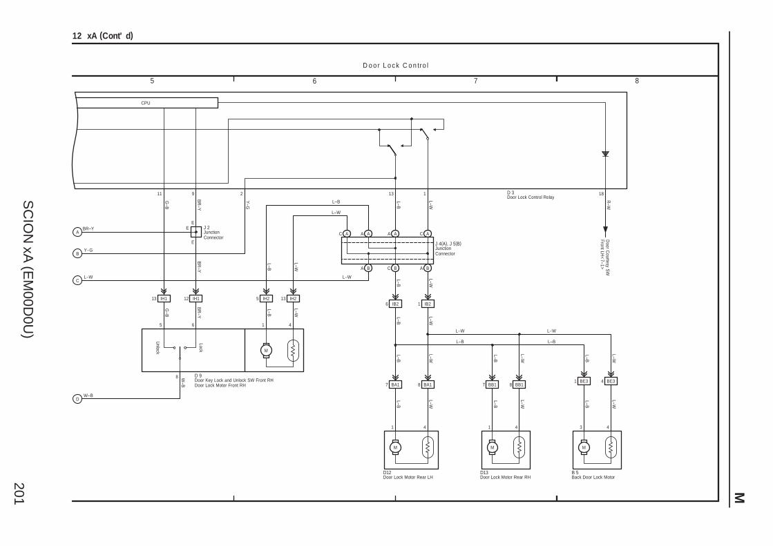
SC
ION
xA (E
M00D
0U)
201 M
7 865
L–W
L–B
43
M
D13D12
BB18BB17BA18BA1
D 9
EE
E
L–B
L–W
M
Door C
ourtesy SW
Front LH<
7–1>
Y–G
L–W
18
R–W
L–W
L–B L–W
L–B
113
L–W
L–B
BR
–Y
G–B
L–B
L–W
L–B
L–W
L–W
L–B
41
11 2
L–W
L–B
IB21IB26
BAC BBA
L–B
ACAAAAAC
7
L–W
L–W
8 W–B
G–B
BR
–Y
L–B
IH213IH25IH112IH113
416
Lock
Unlock
5
M
1 4
L–B
L–W
M
BR–Y
L–W
W–B
D o o r L o c k C o n tro l
12 xA (Cont' d)
JunctionConnector
L–W
L–B
L–W
L–B
B 5
J 4(A), J 5(B)
Back Door Lock Motor
J 2
Door Key Lock and Unlock SW Front RHDoor Lock Motor Front RH
Door Lock Motor Rear LH Door Lock Motor Rear RH
JunctionConnector
9 D 3Door Lock Control Relay
Y–G
BR
–Y
CPU
4 BE31 BE3
A
B
C
D
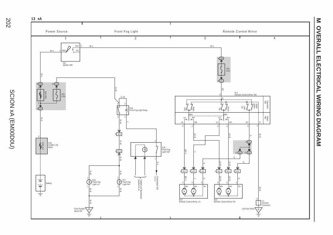
SC
ION
xA (E
M00D
0U)
202
M O
VE
RA
LL
EL
EC
TR
ICA
L W
IRIN
G D
IAG
RA
M
1 2 3 4
A
50A A
M1
13 xA
W–L AM1 IG1
ACC
1
P o w e r S o u rc e F ro n t F o g L ig h t R e m o te C o n tro l M irro r
W–L3
Right/
Dow
n
Select
SW
Operation
SW
LH RH RHLH
Left/U
pDow
n
Up
Right
Left
4 IA1 3 IA1 5 IA1
M M
4 IH1 3 IH1 5 IH1
M M
3 5 4 3 5 4
Y
BR
–Y
Y G
LG–R
LG–B
G
LG–R
LG–B
G
LG–B
BR
–Y
B
HL VL M+HR VR E
1L5
1L121L11
IELeft Kick Panel
G
G
LG–R
1O3
15AACC
1L6
W–B
G
W–B
W–L
763425
8
1J10
120A A
LT
4
2
W–L
1O8
1C1
B–G
Battery
1
15AFOG
1
1
2
3
5
6 ID3
W–B
EBFront FenderApron RH
1
2
1
2
G–W
Y
R–W
G–W
R–W
R–W
R–W
W–B
W–B
GR
F19
4
R–L
Com
bination SW
<4–2>
F10
I10
F18
1 EC1
R–W
F16 F17
3 2
Taillight and Illumination
System
<6–4>
R14 R15 J 1
R 5
Fusible LinkBlock
Ignition SW
JunctionConnector
Remote Control Mirror SW
Remote Control Mirror LH Remote Control Mirror RH
Front FogLight LH
Front FogLight RH
Front FogLight SW
Front Fog Light Relay
MH MV
MH MV M+ MH MV M+

SCION xA (EM00D0U)203
Memo
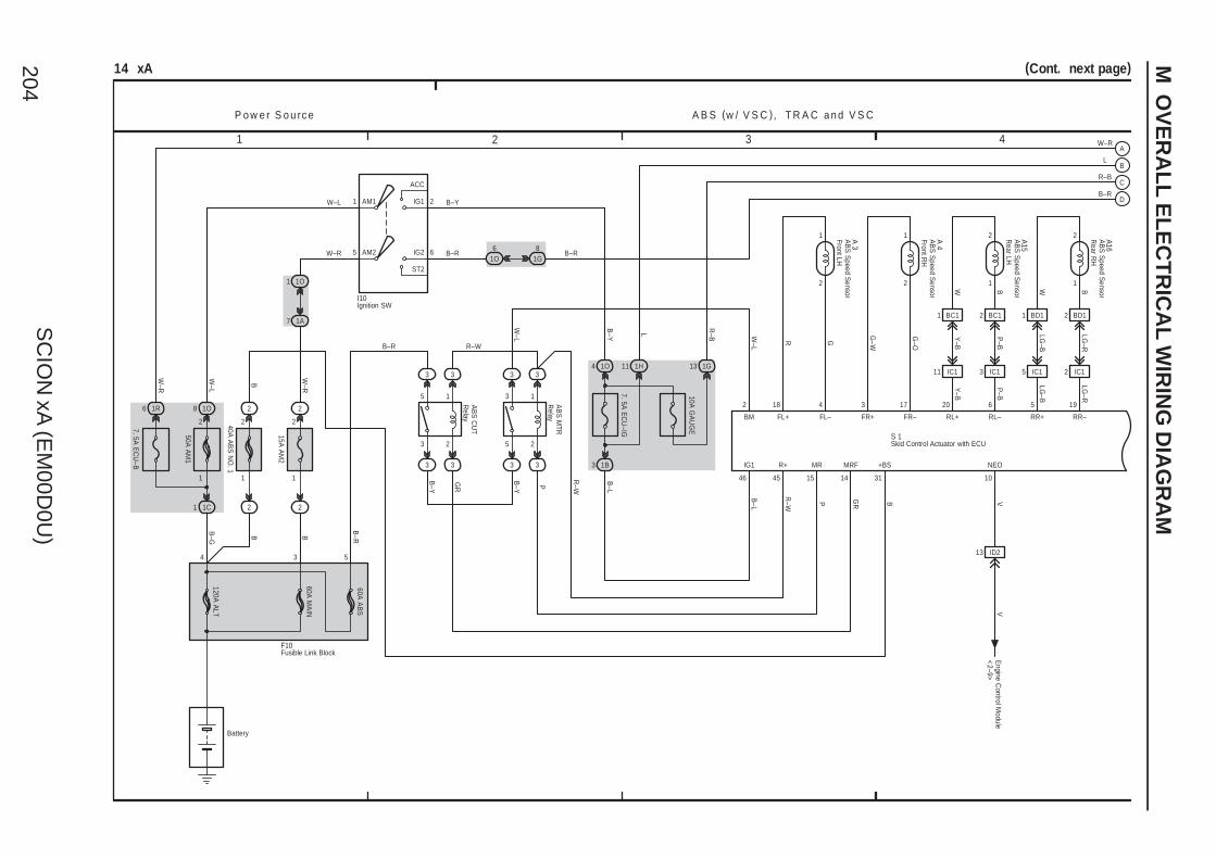
SC
ION
xA (E
M00D
0U)
204
M O
VE
RA
LL
EL
EC
TR
ICA
L W
IRIN
G D
IAG
RA
M
1 2 3 4
(Cont. next page)14 xA
L
R–B
L
534
W–R
2AM1
ST2
IG2
IG1
ACC
1
B–R
60A M
AIN
60A A
BS
AM2
7. 5A E
CU
–IG
120A A
LT
1B3
I10
W–L
B–Y
Battery
2
1
3
5 1
2
3
5
3 3 3 3
3 3 3 3
AB
S C
UT
Relay
AB
S M
TRR
elay
R–W
PB–Y
GR
B–L
B–R
B–Y
1H11
R–W
B–L
R–W P GR B
46 45 15 14 31
2 195620173418
FL–FL+BM FR+ FR– RL+ RL– RR+ RR–
+BSMRFMRR+IG1
2
1 A 3
2
1 A 41
2 A15
1
2 A16
F10
11 IC1 3 IC1 5 IC1 2 IC1
Y–B
P–B
LG–B
LG–R
Y–B
P–B
W–L
R G
G–W
G–O
LG–B
LG–R
V
10
NEO
V
S 1
P o w e r S o u rc e A B S (w / V S C ), T R A C a n d V S C
B–R
1R
W–L
W–L
B
B–G
2
1O8
1C1
2
1
50A A
M1
6
B–Y
7. 5A E
CU
–B
2
2
1
40A A
BS
NO
. 1
1O4
W–R
B
10A G
AU
GE
1G13
R–B
2
2
2
1
15A A
M2
1O1
1A7
65 B–RW–R
B
W–R
13 ID2
2 BD11 BD12 BC11 BC1
W B W B
61O
81G
B–R
Skid Control Actuator with ECU
AB
S S
peed Sensor
Front LH
AB
S S
peed Sensor
Front RH
AB
S S
peed Sensor
Rear LH
AB
S S
peed Sensor
Rear R
H
Fusible Link Block
Ignition SW
Engine C
ontrol Module
<2–9>
A
B
C
D
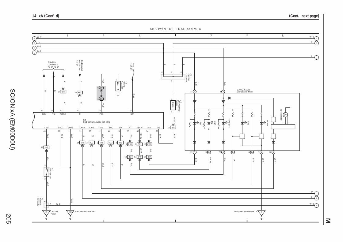
SC
ION
xA (E
M00D
0U)
205 M
7 865
(Cont. next page)14 xA (Cont' d)
2
5
1
E
W–L
W–B
43
CSW
T 6
A
R
J 1
A
4213
W
D/G WFSE
Data LinkConnector 3<2–5><2–6>
R
27
STP
G–W
Stop Light S
W<
10–3>
W–L
W–B
32
GND1
W–B
1
GND2
ED Front Fender Apron LH
W–B
P
1
2
Buzzer
R–W
R–W
B–Y
44
BRL
P
29
WA
R–L
35
WT
BR
–W
36
VSCW
28
Y–R
PKB
R–L
W–R
B
11
CANH
W
25
CANL
R–W
30
BZ
B
L
IND
V 5
34
B–R
W–R
L
R–B
W–B
A B S (w / V S C ), T R A C a n d V S C
S 1
Y–R
1 P 4
16
3
ID2
ID2
W
B–R
17 ID2
1P6
1A1
IE Left KickPanel
ID2 6 ID2
18 IF2 14 IF2 17 IF2
14 ID2 15 ID2
B–Y
W–R
W–R
12
SP1 10 ID2
L
E E E J 7
L L
Skid Control Actuator with ECU
JunctionC
onnector
JunctionC
onnectorParking
Brake S
W
TRA
C O
ff SW
VS
C W
arningB
uzzer
10 EB1
R
40
P
RP
ark/Neutral
Position S
W<
3–6>
9 EB1 8 EB1 13 EB1
R–L
BR
–W
B–R
W–B
B
W
L
B27
A1
30B10
B–R
BR
–W
R–L
P
W–B
C10(A), C11(B)
TRA
C O
FF
VS
C
R–B
A311 B
Slip
W–R
B
AB
S
B–Y
14 B
IFInstrument Panel Brace LH
13 B
10 A
B–R
Combination Meter
BR
AK
E
Speedom
eter
L
24
B
TS
A
B
C
D
A
B
C
D
E
F
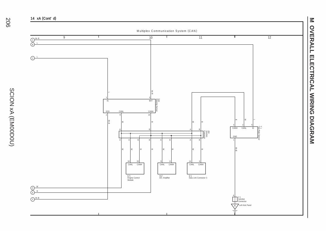
SC
ION
xA (E
M00D
0U)
206
M O
VE
RA
LL
EL
EC
TR
ICA
L W
IRIN
G D
IAG
RA
M
9 10 11 12
B
B
A
A
W B W B
W BBW
L
W–R
W–B
B W L
W–B
J10
S15
Y 1
A B
A B
1 3
2
3 2 5
1
9 10
GND
CANL CANH
IG BAT
ESS
CANH CANL IG
Left Kick PanelIE
JunctionC
onnector
Steering S
ensor
Yaw
Rate S
ensor
14 xA (Cont' d)
M u ltip le x C o m m u n ic a tio n S y s te m (C A N )
W–R
W–B
B
W
L
L
A
JunctionConnector
J 1
CANHCANL
9 8
A/C AmplifierA17
A B
BWCANHCANL
34 33
Engine ControlModule
E 5
A B
BW
CANHCANL
14 6
Data Link Connector 3D 1
A
B
C
D
E
F
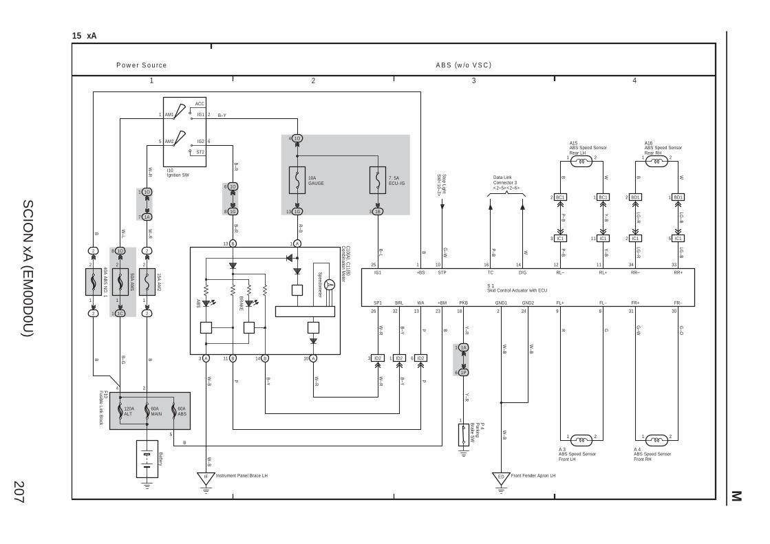
SC
ION
xA (E
M00D
0U)
207 M
1 2 3 4
B
IF
ID2
15 xA
1C
Battery
1
60AMAIN
B–G
60AABS
5
4
50A A
M1
1
ACC
IG1AM1 2
1O8
2
W–L
1O4
10AGAUGE
7. 5AECU–IG
B–Y
1G13 1B3
1
1 A
3 A
R–B
11 B
13
25 10
Instrument Panel Brace LH
W–B
W–B
P
G–W
B–L
23
B
B
Stop Light
SW
<10–3>
Data LinkConnector 3<2–5><2–6>
16 14
P–B
W
1 2
9 8
R G
1 2
31 30
G–W
G–O
1 2
2 IC1 5 IC1
34 33
B W
LG–R
LG–B
P o w e r S o u rc e A B S (w /o V S C )
ED Front Fender Apron LH
2 24
W–B
W–B
BD12 1 BD1
LG–R
LG–B
WA +BM FL+ FL– FR+
IG1 STP TC D/G RR– RR+
FR–GND1 GND2
W–B
6
120AALT
W–R
2
15A A
M2
2
2
1
1A7
1O1
B
5 AM2
W–R
6
ST2
IG2
B–R
AB
S
1G8
1O6
B–R
13 B
14 B 10 A 1 ID23 ID2
32
B–Y
BRL
26
W–R
SP1
A16
P B–Y
W–R
W–R
B–Y P
A15
RL+RL–
Y–B
P–B
BC112 BC1
Y–B
P–B
WB
1112
IC111IC13
21
A 3 A 4
1A1
1P6
1
Y–R
Y–R
18
PKB
S 1
2
C10 (A ), C
11 (B )
I10
Skid Control Actuator with ECU
ABS Speed SensorFront LH
ABS Speed SensorFront RH
ABS Speed SensorRear LH
ABS Speed SensorRear RH
Com
bination Meter
Ignition SW
BR
AK
E
Speedom
eter
2
40A A
BS
NO
. 1
2
2
1
B
1
B
+BS
Fusible Link Block
F10
Parking
Brake S
W
P 4
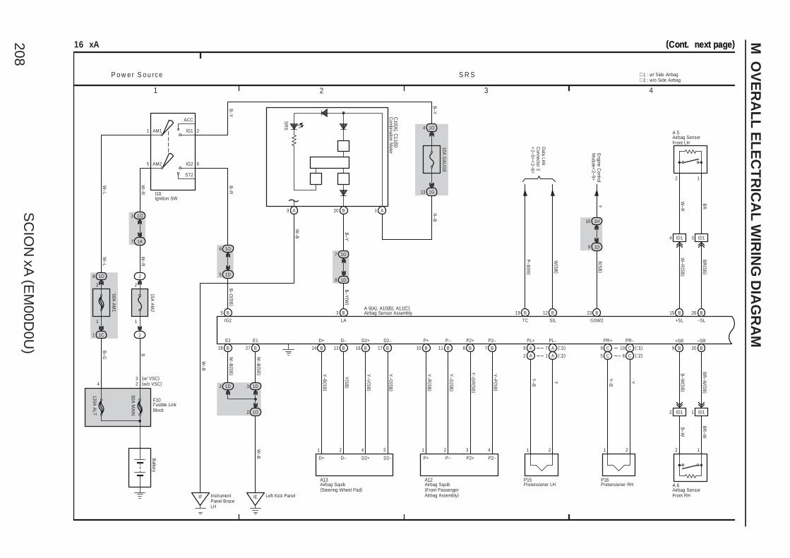
SC
ION
xA (E
M00D
0U)
208
M O
VE
RA
LL
EL
EC
TR
ICA
L W
IRIN
G D
IAG
RA
M
1 2 3 4
(Cont. next page)(Cont. next page)
D2–D2+D–
9 1D
1
16 xA
1
2
60A M
AIN
W–R
B
7 1A
1 1O
2
15A A
M2
2
P o w e r S o u rc e S R S
1O6
1D5
5 B 3 B
IE
1G7
1D8
B–O
(SB
)
B–Y
(W)
19 B 12 B
P–B
(W)
W(S
B)
TC SILLAIG2
B23
B–R
4 ID1 3 ID1
+SL
B15 26 B
2 1
W–R
BR
W–R
(SB
)
BR
(SB
)
–SL
28 B 27 B
1O2
1D31D2
W–B
(SB
)
W–B
(SB
)W
–B
D+
16 B 17 B
Y–V
(SB
)
Y–O
(SB
)
1 2 1 2
8 A 7 A 9 C 10 C
Y–B Y Y–B Y
E2 E1 D2+ D2– PL+ PL– PR+ PR–
2
2 ID1 1 ID1
9 B 20 B
+SR –SR
B–W
(SB
)
BR
–W(S
B)
B–W
BR
–W
2
1H10
Engine C
ontrolM
odule<2–9>
YB
(SB
)
GSW2
W–B
W–B
SR
S
20 B
B–Y
W–R
3 A
5
ACC
IG1
Battery
IG2
ST2
AM1 2
6AM2
1 A
B–Y
R–B
10A G
AU
GE
B–Y
1O4
13 1G
IF InstrumentPanel BraceLH
Left Kick Panel
C10 (A ), C
11 (B )
A 5
14 B 13 B
Y–B
(SB
)
Y(S
B)
D+ D–
A13
1 2 4 3
P2–P2+P–P+
8 B 7 B
Y–G
R(S
B)
Y–P
(SB
)
P2+ P2–
10 B 11 B
Y–R
(SB
)
Y–G
(SB
)P+ P–
A12
1 2 3 4
2 A 1 A 5 C 6 C (∗2)
(∗1)
(∗2)
(∗1)
P15 P16A 6
I10
3(w/o VSC)(w/ VSC)
50A A
M1
120A A
LT
4
1O8
1C1
B–G
F10
W–L
W–L
1
A 9(A), A10(B), A11(C)
∗ 2 : w/o Side Airbag∗ 1 : w/ Side Airbag
1
2
Airbag Squib(Front PassengerAirbag Assembly)
Airbag Squib(Steering Wheel Pad)
Airbag Sensor Assembly
Com
bination Meter
Airbag SensorFront LH
Airbag SensorFront RH
Fusible LinkBlock
Ignition SW
Pretensioner LH Pretensioner RH
Data Link
Connector 3
<2–5>
<2–6>

SC
ION
xA (E
M00D
0U)
209 M
7 865
S R S
16 xA (Cont' d)
15 C
B
BBR–
3
BBR–
(∗1 )
17 C
W
BBR+
4
BBR+
(∗1 )
1 2
5 C 6 C
Y–R
Y–G
SFR+ SFR–
(∗1 )
(∗1 )
(∗1 )
ICR–ICR+
(∗1 )21
8 C 7 C
ICR+ ICR–
Y–V
Y–O
18 A
B
BBL–
BBL–
(∗1 )
S 7
3
16 A
W
BBL+
BBL+
(∗1 )
4
12 A
Y–R
SFL+
(∗1 )
1
11 A
Y–G
SFL–
(∗1 )
2
(∗1 )
(∗1 )
9 A 10 A
ICL+ ICL–
Y–V
Y–O
1 2
ICL+ ICL–
S10Side Airbag SensorRear RH
Side Airbag SensorRear LH
S 9
BCR–
2
BCR+
1
2
BCL–
1
BCL+
(∗1 )
BCL–
1
R(∗1 )
BCL+
2
G
1
(∗1 )
BCR–
G
2
(∗1 )
BCR+
R
S11C15
S 8S12
C16
3 A11 A8 C 8 A (∗2)
2 A (∗1)
7 A (∗2)
3 A (∗1)4 A19 A14 C
RBE+ LBE+ LSP+ LSP–
1 31
5 4 2
B
W
G–Y
B
R
R
W–R
B W G–Y
O
R
R
3
A 9(A), A10(B), A11(C)
Com
bination Meter
<10–2>
∗ 2 : w/o Side Airbag∗ 1 : w/ Side Airbag
Buckle S
WR
H
Airbag Sensor Assembly
Curtain Shield AirbagSquib LH
Curtain Shield AirbagSquib RH
Side Airbag SensorFront LH
Side Airbag SensorFront RH
Side AirbagSquib LH
Side AirbagSquib RH
Seat PositionAirbag Sensor
B 6Buckle SW LH
12 C
3 C
RBE–
B
2
Occupant
Detection
Com
binationM
eter<10–2>
Buckle S
W R
HB 7
LBE–
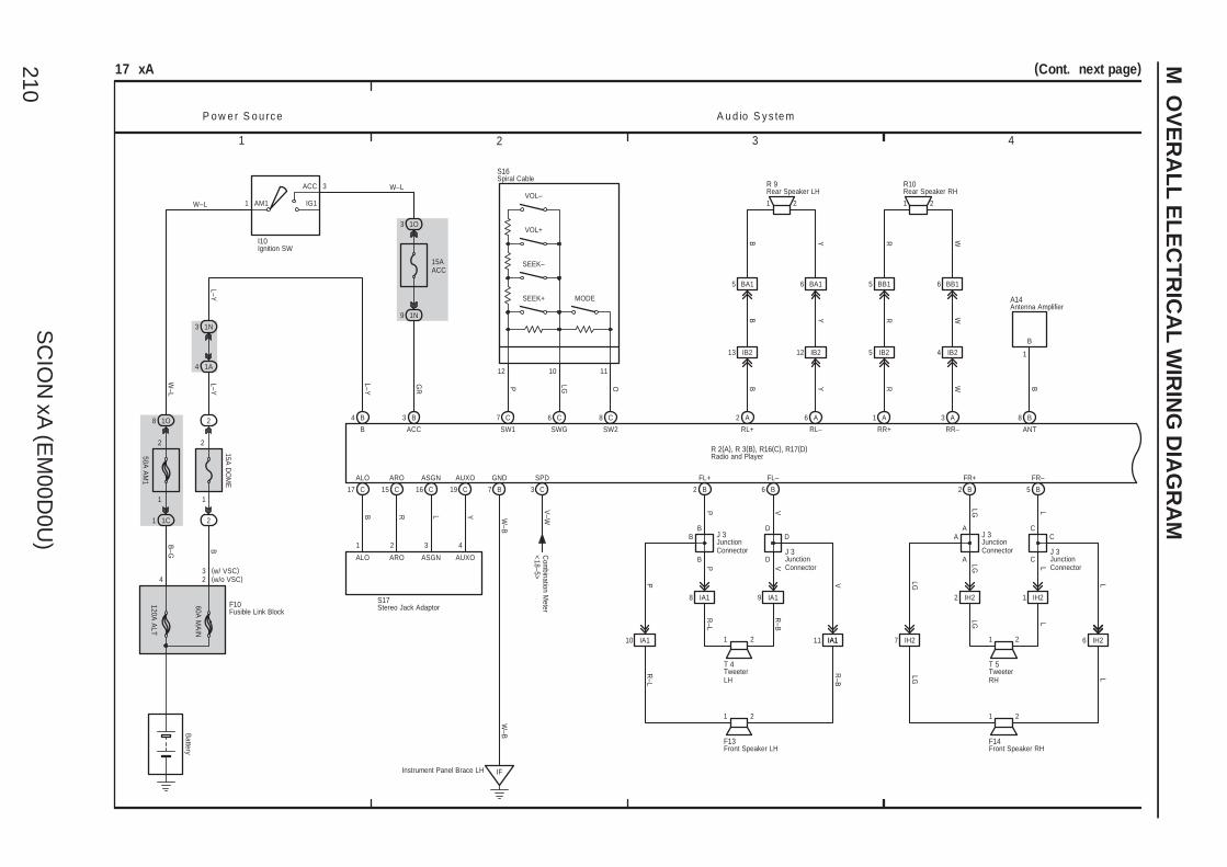
SC
ION
xA (E
M00D
0U)
210
M O
VE
RA
LL
EL
EC
TR
ICA
L W
IRIN
G D
IAG
RA
M
1 2 3 4
IB24
1
L–Y
IB2
B Y
17 xA
60A M
AIN
W–L
W–L
B
B–G
120A A
LT
2
AM1 IG1
ACC
1
1O8
1C1
50A A
M1
Battery
P o w e r S o u rc e A u d io S y s te m
15A D
OM
E
2
1N3
1A4
1O3
15AACC
1N9
IF
RL–RL+
1 2
RR–RR+
W–B
W–B
A6A2 A31 A
13
GR
L–Y
L–Y
I10
W–L
Y
B7
2
3
B WR
2 B 6 B
3 B4 B
ACCB
GND FL+ FL–
24
2
1
IB25
11 22
R W
5
IB212
1 2
P V
BA1
F10
3(w/o VSC)(w/ VSC)
6 BA1 5 BB1 6 BB1
8 IA1 9 IA1
YB WR
R 9 R10
T 4
F13
R–L
R–B
ANT
B8
B
1
B
A14
R 2(A), R 3(B), R16(C), R17(D)
Antenna Amplifier
Fusible Link Block
Front Speaker LH
Ignition SW
Radio and Player
Rear Speaker LH Rear Speaker RH
TweeterLH
17 C 15 C 16 C 19 C
ALO ARO ASGN AUXO
Stereo Jack AdaptorS17
1 2 3
ALO ARO ASGN AUXO
B R L Y
3 C
SPD
V–W
Com
bination Meter
<18–5>
7 C 8 C6 C
P OLG
SW1 SW2SWG
Instrument Panel Brace LH
D
D JunctionConnector
J 3
D
V
B
B
B
11 IA1IA110 IA1
VP
R–B
R–L
FR+ FR–
1 2
2 B 5 B
1 2
LG L
2 IH2 1 IH2
T 5
F14
LG L
Front Speaker RH
TweeterRH
LG L
LG L
IH2
A
A
CA
C
L
C
7
JunctionConnector
J 3JunctionConnector
J 3JunctionConnector
J 3
LGP
6 IH2
(Cont. next page)
SEEK+
SEEK–
VOL+
VOL–
MODE
12 10 11
S16Spiral Cable
4
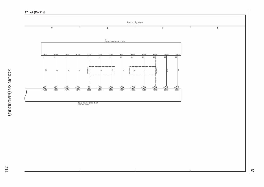
SC
ION
xA (E
M00D
0U)
211 M
7 865
17 xA (Cont' d)
1 D 3 D 4 D 6 D 7 D 8 D 9 D 10 D 11 D 12 D 13 D 14 D 16 D
FWGD ACID FWPW ACPW DOGD DOTX DORX ACDT AUDL AUDR AGND DGND SGND
LG
FWGD
1 3
ACID
G
4
FWPW
P
6
ACPW
V
7
DOGD
8
DOTX
B
9
DORX
W
10
ACDT
Y
11
AUDL
R
12
AUDR
L
13
AGND
14
DGND
W–B
16
SGND
BR
Option Connector (IPOD Unit)Z 7
(Shielded )
(Shielded )
A u d io S y s te m
Radio and PlayerR 2(A), R 3(B), R16(C), R17(D)
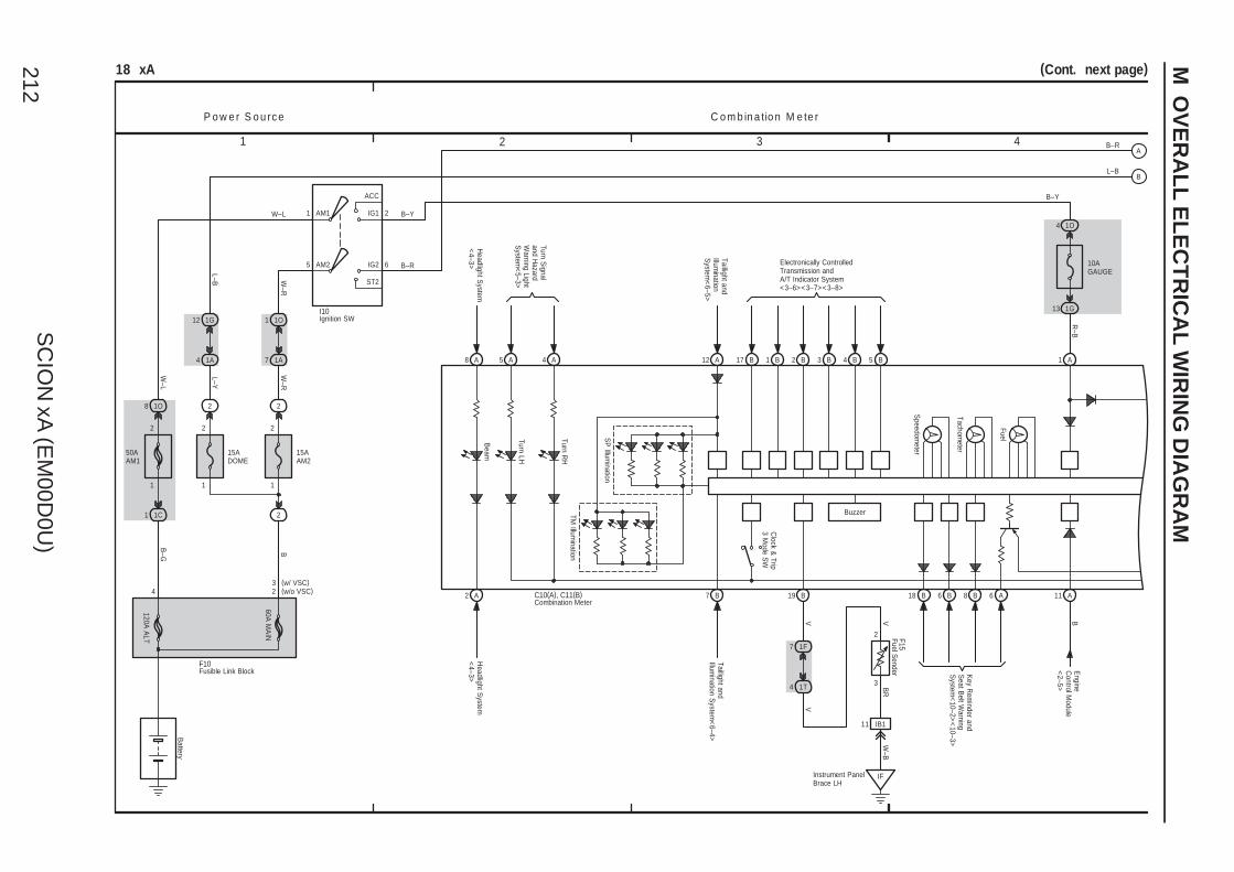
SC
ION
xA (E
M00D
0U)
212
M O
VE
RA
LL
EL
EC
TR
ICA
L W
IRIN
G D
IAG
RA
M
1 2 3 4
(Cont. next page)18 xA
B3 B4 B5
R–B
1
2
60A M
AIN
4 2
W–R
B–Y
B–R
W–L
W–L
W–R
B
B–G
7 1A
1 1O
2
15AAM2
120A A
LT
2
AM25 6
2AM1
ST2
IG2
IG1
ACC
1
50AAM1
1O8
1C1
Battery
2
1 1
2
L–BL–Y
4 1A
12 1G
2
15ADOME
I10
F10
3(w/o VSC)(w/ VSC)
Fusible Link Block
Ignition SW
2 B1 B17 B12 A4 A5 A8 A
Speedom
eter
Tachometer
Fuel
1 A
1G13
10AGAUGE
1O4
Beam
Turn LH
Turn RH
SP
Illumination
TM Illum
ination
2 A
V
3
2
BR
F15Fuel S
ender
Taillight andIllum
inationS
ystem<
6–5>
Turn Signal
and Hazard
Warning Light
System
<5–3>
Headlight S
ystem<
4–3>
B7
Taillight andIllum
ination System
<6–4>
Headlight S
ystem<
4–3> Electronically ControlledTransmission andA/T Indicator System<3–6><3–7><3–8>
Clock &
Trip3 M
ode SW
18 B 6 B 8 B 6 A
Key R
eminder and
Seat B
elt Warning
System
<10–2>
<10–3>
19 B
1F7
1T4
IFInstrument PanelBrace LH
11 IB1
VV
W–B
A11
Engine
Control M
odule<
2–5>
B
Buzzer
P o w e r S o u rc e C o m b in a tio n M e te r
Combination MeterC10(A), C11(B)
B–R
B–Y
L–B
A
B
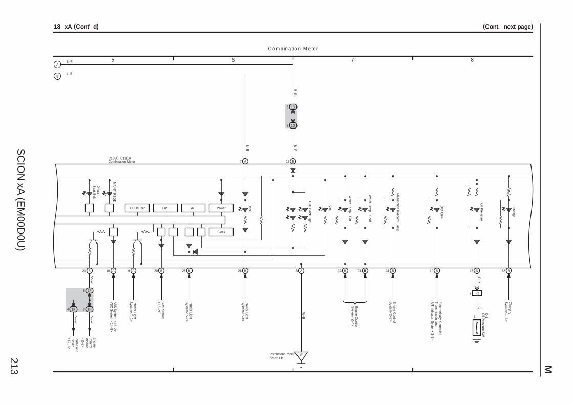
SC
ION
xA (E
M00D
0U)
213 M
7 865
(Cont. next page)
L–B
18 xA (Cont' d)
AB
S S
ystem <
15–2>V
SC
System
<14–8>
ODO/TRIP Fuel A/T
Clock
Power
21 B 10 A
1F6
3 1H
V–W
V–W
Engine
Control
Module
<2–8>
9 A
Interior LightS
ystem<
7–2>
Driver
Seat B
elt
MA
INT R
EQ
D
20 B
SR
S S
ystem<
16–2>
25 B
Interior LightS
ystem<
7–2>
7 A
26 B
Interior LightS
ystem<
7–1>
Door
LCD
Back Light
13 B
1O6
1G8
B–R
B–R
SR
S
Water Tem
p. Hot
Water Tem
p. Cool
3 A
IFInstrument PanelBrace LH
W–B
Malfunction Indicator Lam
p
31 B
Engine C
ontrolS
ystem<
2–3>
O/D
OFF
12 B
Electronically C
ontrolledTransm
ission andA
/T Indicator System
<3–5>
Oil P
ressureO
1
16 B
2 IF2
1
GG
–YO
il Pressure S
W
Charge
32 B
Charging
System
<1–4>
C o m b in a tio n M e te r
Combination MeterC10(A), C11(B)
B–R
L–B
1K4
V–W
Radio and
Player
<17–2>
24 BB23 B
Engine C
ontrolS
ystem<
2–4>
A
B

SC
ION
xA (E
M00D
0U)
214
M O
VE
RA
LL
EL
EC
TR
ICA
L W
IRIN
G D
IAG
RA
M
9 10 11 12
30 B B1027 BB14
VS
C S
ystem<
14–7>
18 xA (Cont' d)
15 B
ED Front FenderApron LH
Y–R
W–B
2
1
Y–R
ID32
B 2B
rake FluidLevelW
arning SW
BR
AK
E
AB
S
B11
VS
C S
ystem<
14–7><
14–8>A
BS
System
<15–1>
<15–2>
TRA
C O
FF
Slip
VS
C
C o m b in a tio n M e te r
Combination MeterC10(A), C11(B)
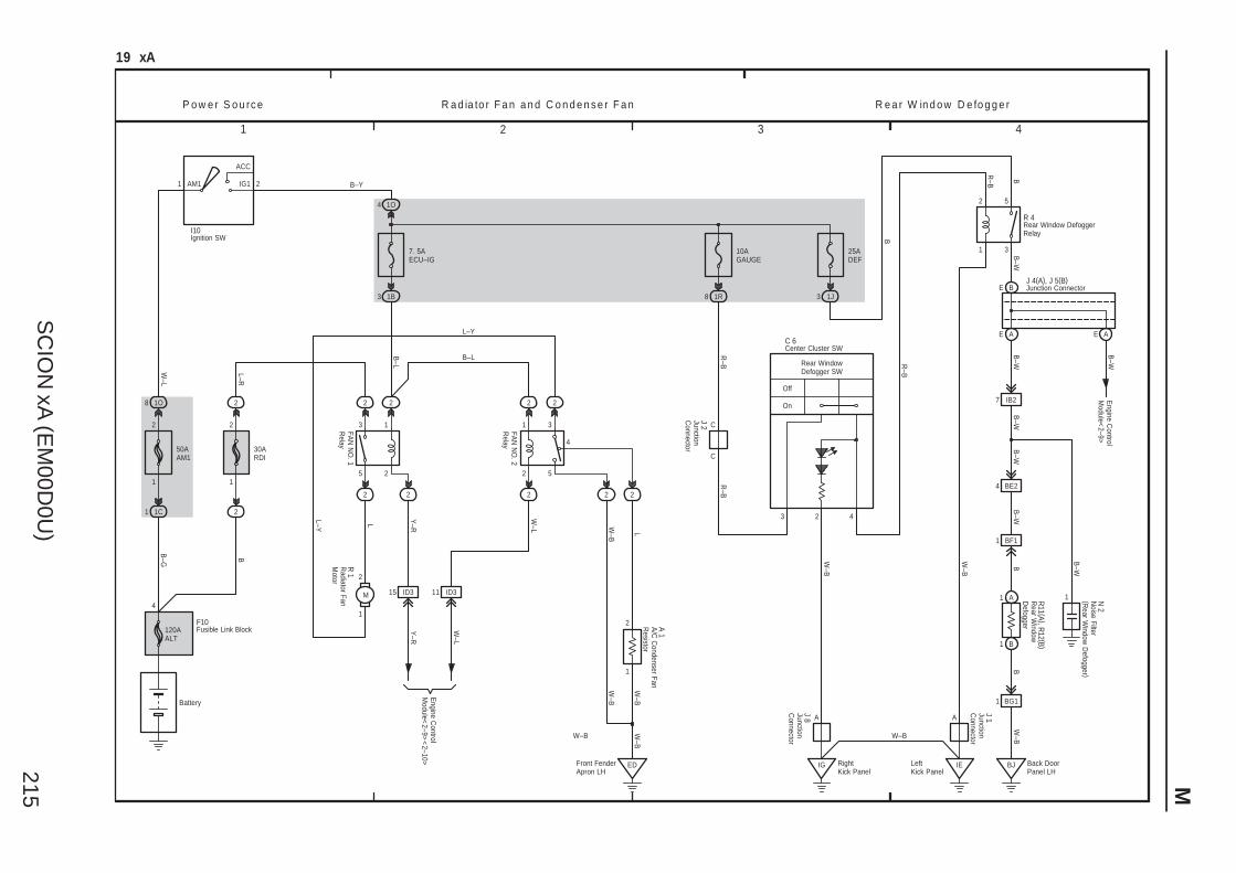
SC
ION
xA (E
M00D
0U)
215 M
1 2 3 4
3 1J
IB2
1
25ADEF
Front FenderApron LH
19 xA
2
1C1 2
30ARDI
1
2
B–G
50AAM1
B
1
120AALT
1O8
1O4
2
1
ACC
IG1AM1 2 B–Y
10AGAUGE
7. 5AECU–IG
1B3 1R8
W–L
4
Battery
2
1
5
3
22
2 2
FAN
NO
. 1R
elay
L–R
2
1
5
3
4
2 2
2 2
2
M
1
2
Y–R
Y–R
ED
L–Y
B–L
LL–Y
2
1
W–B
L
W–B
W–B
B–W
1 B
1 A
B–L
B–W
7
W–B
BJ Back DoorPanel LH
5
P o w e r S o u rc e R a d ia to r F a n a n d C o n d e n s e r F a n
FAN
NO
. 2R
elay
R e a r W in d o w D e fo g g e r
3
2
1
B
Off
On
IG RightKick Panel
W–B
A
Rear WindowDefogger SW
2 4
IELeftKick Panel
W–L
W–B
W–B
F10
I10
R 1
15 ID3 11 ID3
Engine C
ontrolM
odule<2–9>
<2–10>
A 1
C
R–B
3R
–B
1 BG1
BF1
4 BE2
A
1
R 4
R–B
B–W
B
B–W
W–B
W–B
BB
–W
J 8
R11 (A ), R
12 (B )
N 2
J 1
C 6
A/C
Condenser Fan
Resistor
Center Cluster SW
Fusible Link Block
Ignition SW
JunctionC
onnector
JunctionC
onnector
Noise Filter
(Rear W
indow D
efogger )
Radiator Fan
Motor
Rear Window DefoggerRelay
Rear W
indowD
efogger
J 2JunctionC
onnector
C
E B
E A E A
Engine C
ontrolM
odule<2–9>
Junction ConnectorJ 4(A), J 5(B)
B–W
R–B
B
B–W
W–L
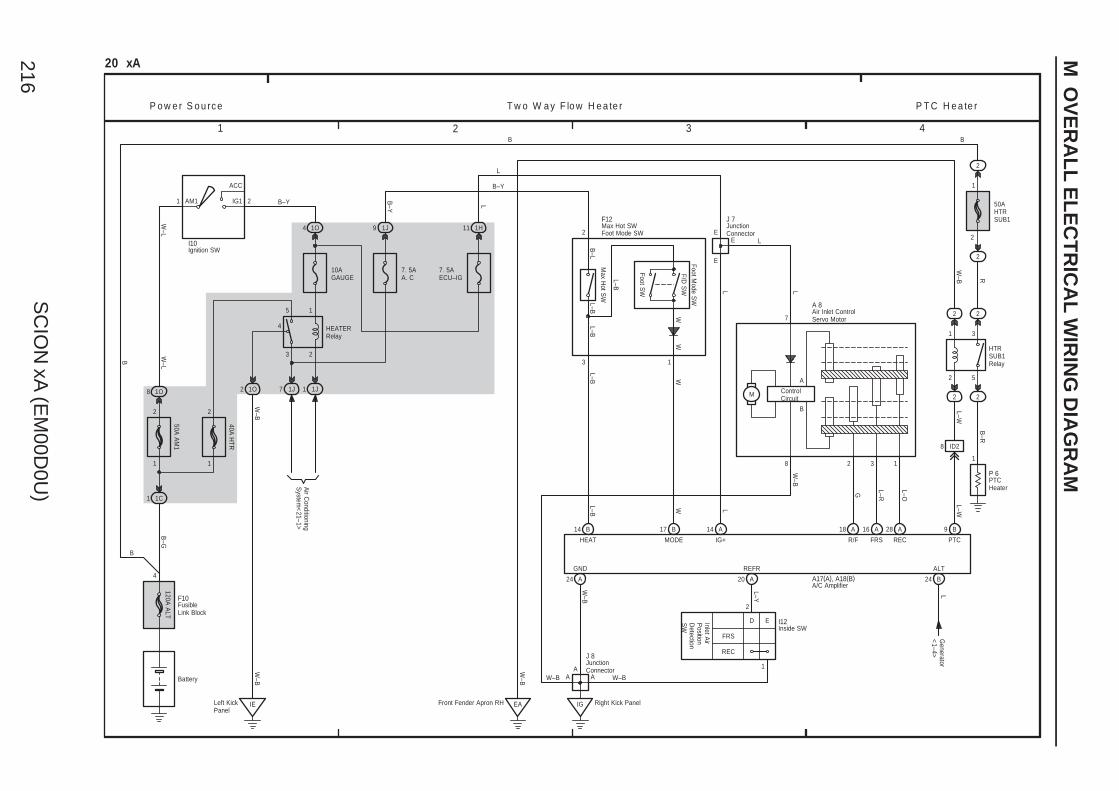
SC
ION
xA (E
M00D
0U)
216
M O
VE
RA
LL
EL
EC
TR
ICA
L W
IRIN
G D
IAG
RA
M
1 2 3 4
Max H
ot SW
2
F/D S
WW
20 xA
1C1
50A A
M1
40A H
TR
1O8
4 1O
1
ACC
IG1AM1 2
10AGAUGE
B–G
B–Y
3
5
2
1
4 HEATERRelay
1J11O2
IELeft KickPanel
7. 5AA. C
PTC
1J9
2
IG Right Kick Panel
L–B
2
2
50AHTRSUB1
2
2
B–R
2
3
Foot SW
1
P o w e r S o u rc e P T C H e a te r
Battery
1
B–L
8 ID2
B
W–BW–B
L
W–B
B
W–L
W–L
L–B W
L–B
W L
L–O
L–RG
L–W
L–B
L–Y
W–B
W–B
L–B
R
7
L–W
8 132
E
AA
A
E
B
L L
1
2
IG+
ALT
RECFRSR/FHEAT MODE
Generator
<1–4>
L
GND REFR
1 1
2 2
T w o W a y F lo w H e a te r
1H11
7. 5AECU–IG
E
W–B
2
1
5
3
W–B
M ControlCircuit
B
A
2
1
ED
REC
FRS
B
L
B–Y
B–Y
Foot Mode S
W
L
I10
F12
Inlet Air
Position
Detection
SW I12
P 6
A 8
J 7
Air Inlet ControlServo Motor
Ignition SW
Inside SW
JunctionConnector
JunctionConnector
Max Hot SW
PTCHeater
J 8
1J7
Foot Mode SW
Air C
onditioningS
ystem<
21–1>
120A A
LT
4
FusibleLink Block
F10
14 B 17 B 14 A 18 A 16 A 28 A 9 B
24 A 20 A 24 B
EA
W–B
HTRSUB1Relay
A/C AmplifierA17(A), A18(B)
Front Fender Apron RH
W
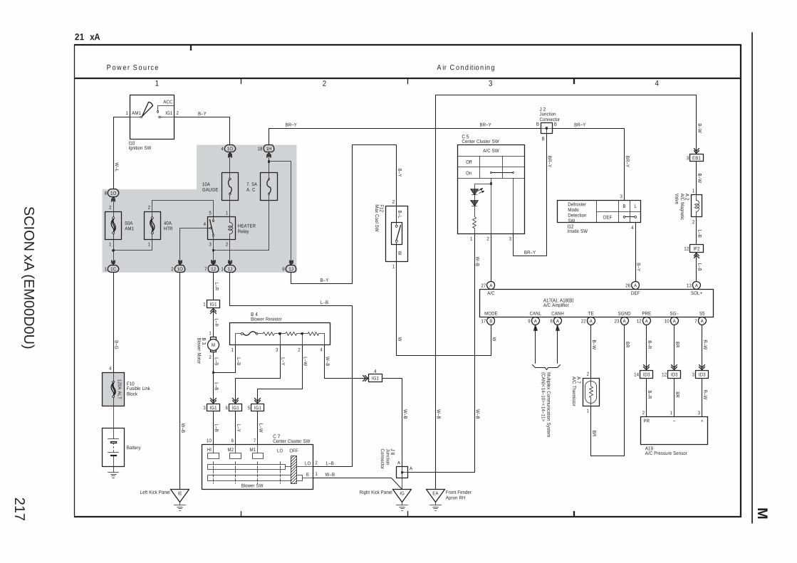
SC
ION
xA (E
M00D
0U)
217 M
1 2 3 4
IF2
IE
SOL+
21 xA
1C1
50AAM1
40AHTR
1O8
4 1O
10AGAUGE
B–G
B–Y
W–B
W–L
3
5
2
1
4 HEATERRelay
1J11J71O2
1H18
L–R
HI M2 M1
10 6 7
LO OFF
2
1
L–B
EB1
A
1
Off
On
W–B
L–W
P o w e r S o u rc e A ir C o n d itio n in g
Battery
Blower SW
11
22
L–Y
L–B
W–B
3
M
L–RL–B
L–B
L–B
L–Y
L–W
W–B
W–B
IGRight Kick PanelLeft Kick Panel
12
3
4
LB
DEF
A/C SW
C 5
1 2 3
B
B B
J 2
BR–Y BR–Y
BR–Y
DefrosterModeDetectionSWI12
W–B
W
BR
–Y
BR
–Y
A/C
A 7
A 2
2
B–W
B–W
L–BL–B
DEF
BR
B–W
B–Y
A
C 7
A/C
Magnetic
Valve
A/C
Thermistor
Center Cluster SW
Center Cluster SW
Inside SW
JunctionConnector
B 4Blower Resistor
JunctionC
onnector
J 8
1
ACC
IG1AM1 2
Ignition SWI10
BR–Y
L–B
7. 5AA. C
TE SGND
BR
3 IG1 6 IG1 5 IG1
IG14
1 IG1
1 3 2 4
2
1B 3B
lower M
otor
120A A
LT
4
Fusible LinkBlock
F10
E
LO
14 ID3 12 ID3 3 ID3
S5SG–PRE
B–R
BR
R–W
R–W
BR
B–R
2 1 3
PR – +
A/C Pressure SensorA19
Multiplex C
omm
unication System
(CA
N)<
14–10><
14–11>
CANHCANL
A/C AmplifierA17(A), A18(B)
EA Front FenderApron RH
W–B
1
2
1J9
B–Y
1
2
B–L
B–Y
W W
F12M
ax Cool S
W
27 A 26 A 13 A
17 B 22 A 23 A 12 A 10 A 7 A9 A A8
MODE
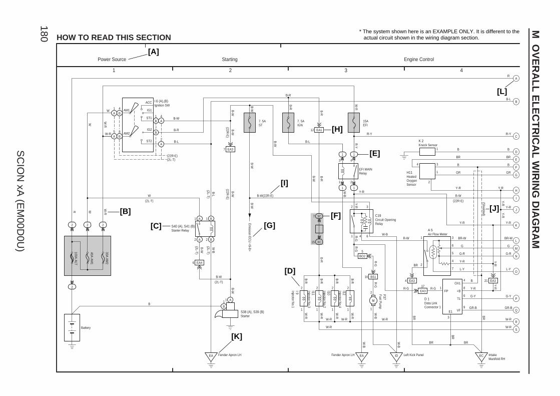
2
4
1 2 3 4
HOW TO READ THIS SECTION
ACC
IG1
ST1
IG2
ST2
AM2
6 EA4
7 EA3
2 A 2 B
1 A 1 B
4B
5A
B
1B
EA
1
3C15
3C7
41 6
1
1
1
3
2 3
1
2
4 3
1
1
3
6
5
4
7
4 EA3
12 EA1
BO25
21 EA3
ID ECEA
1
2
1
2
1
2
1
2
16 BS1
1
2
M
EA317 1
4
8
6
9B
W
W-R
B-W
B-R
B-L B-L
B-W(22R-E)
B-W
W-R
R-G
B
BR
B
GR
Y-R
B-W
Y-R
BR-W
G
G-R
Y-R
L-Y
Y-R
G-Y
GR-B
W-BR-W
R-G
BR
W-R
W-R
Y-R
R-Y
B-W
Y-R
Y-R
W
B-R
WR W-R
W-R
W
B-L
B-W
B-W
B-W
B-R
B-R
B-R
B-R
B-R
B-R
W-R
W-R
W-R
W-R B
R
BR
W-B
W-B
R-G
Y-R
W-B
B-R
Y-R
B
Y-R
W-B
B-W
W-B
B-R
R-Y
W-R
B-W
BR
100A A
LT
40A A
M1
30A A
M2
4A
2A
1A
7
(22R-E)(2L-T)
7. 5AST
7. 5AIGN
B-W
R-G
15AEFI
R-G
FP
OX1
+B
T1
VF
B-L
(2L-T)
1 A1B
R
AM1
B-W
2
BR
E1
3
(2L-T)
(22R-E
)
(2L-T)
(2L-T)
B-W
R-G
Y-R
Y-R
Y-R
W-R W-R
B
8B
A
B
C
D
E
F
G
H
I
K
L
M
N
O
P
Q
R
S
J
1
R-Y
B
BR
GR
(22R-E)
BR-W
G
G-R
L-Y
GR-B
G-Y
W-R
(2L-T)
BR
(22R-E
)
* The system shown here is an EXAMPLE ONLY. It is different to the actual circuit shown in the wiring diagram section.
[A]
[B]
[C]
[D]
[E]
[G][F]
[H]
[I]
[J]
[K]
[L]
C19
A 5
H11
K 2
I 9 I11
I10
I12 F37 D 1
I 6 (A),(B)
S40 (A), S41 (B)
S38 (A), S39 (B)
2
2 2 2
B-W
Fender Apron LH
(Shielded)
EFI MAINRelay
Fender Apron LH Left Kick Panel
Starting
IntakeManifold RH
Power Source Engine Control
Circuit OpeningRelay
Air Flow Meter
HeatedOxygenSensor
Knock Sensor
Injector No.1
Injector No.3
Injector No.2
Injector No.4
Fuel Pum
p
Data LinkConnector 1
Ignition SW
Starter Relay
Starter
Battery
Em
ission EC
U <9-8>
M O
VE
RA
LL
EL
EC
TR
ICA
L W
IRIN
G D
IAG
RA
M
180
SC
ION
xA (E
M00D
0U)

M181
SC
ION
xA (E
M00D
0U)
[A] : System Title
[B] : Indicates the wiring color.
Wire colors are indicated by an alphabetical code.
B = Black W = White BR = Brown
L = Blue V = Violet SB = Sky Blue
R = Red G = Green LG = Light Green
P = Pink Y = Yellow GR = Gray
O = Orange
The first letter indicates the basic wire color and thesecond letter indicates the color of the stripe.Example: L – Y
L(Blue)
Y(Yellow)
[C] : The position of the parts is the same as shown inthe wiring diagram and wire routing.
[D] : Indicates the pin number of the connector.The numbering system is different for femaleand male connectors.Example : Numbered in order
from upper left tolower right
Numbered in orderfrom upper right tolower left
The numbering system for the overall wiring diagram is the same as above
[E] : Indicates a Relay Block. No shading is used and only the Relay Block No. is shown to distinguishit from the J/B.Example : Indicates Relay Block No.1
[F] : Junction Block (The number in the circle is the J/B No. and the connector code is shown beside it). Junction Blocks are shaded to clearly separate them from other parts.
3C indicates thatit is insideJunction BlockNo.3
Example:
[G] : Indicates related system.
[H] : Indicates the wiring harness and wiring harnessconnector. The wiring harness with maleterminal is shown with arrows ( ).Outside numerals are pin numbers.
Female Male ( )
[I] : ( ) is used to indicate different wiring andconnector, etc. when the vehicle model, engine type, or specification is different.
[J] : Indicates a shielded cable.
[K] : Indicates and located on ground point.
[L] : The same code occuring on the next page indicates that the wire harness is continuous.

SYSTEM INDEXM
OV
ER
AL
L E
LE
CT
RIC
AL
WIR
ING
DIA
GR
AM
182
SC
ION
xA (E
M00D
0U)
SYSTEMS LOCATION SYSTEMS LOCATIONABS (w/ VSC) 14–2. . . . . . . . . . . . . . . . . . . . . . . . . . . . . . . . . . . . . . . . . . . . . .
ABS (w/o VSC) 15–2. . . . . . . . . . . . . . . . . . . . . . . . . . . . . . . . . . . . . . . . . . . .
Air Conditioning 21–2. . . . . . . . . . . . . . . . . . . . . . . . . . . . . . . . . . . . . . . . . . . .
Audio System 17–2. . . . . . . . . . . . . . . . . . . . . . . . . . . . . . . . . . . . . . . . . . . . . .
Back–Up Light 8–2. . . . . . . . . . . . . . . . . . . . . . . . . . . . . . . . . . . . . . . . . . . . . .
Charging 1–4. . . . . . . . . . . . . . . . . . . . . . . . . . . . . . . . . . . . . . . . . . . . . . . . . . .
Cigarette Lighter 7–4. . . . . . . . . . . . . . . . . . . . . . . . . . . . . . . . . . . . . . . . . . . .
Combination Meter 18–2. . . . . . . . . . . . . . . . . . . . . . . . . . . . . . . . . . . . . . . . .
Door Lock Control 12–2. . . . . . . . . . . . . . . . . . . . . . . . . . . . . . . . . . . . . . . . . .
Electronically Controlled Transmission and A/T Indicator 3–2. . . . . . . . .
Engine Control 2–2. . . . . . . . . . . . . . . . . . . . . . . . . . . . . . . . . . . . . . . . . . . . . .
Front Fog Light 13–2. . . . . . . . . . . . . . . . . . . . . . . . . . . . . . . . . . . . . . . . . . . . .
Front Wiper and Washer 8–3. . . . . . . . . . . . . . . . . . . . . . . . . . . . . . . . . . . . .
Headlight 4–2. . . . . . . . . . . . . . . . . . . . . . . . . . . . . . . . . . . . . . . . . . . . . . . . . . .
Horn 4–4. . . . . . . . . . . . . . . . . . . . . . . . . . . . . . . . . . . . . . . . . . . . . . . . . . . . . . .
Ignition 1–2. . . . . . . . . . . . . . . . . . . . . . . . . . . . . . . . . . . . . . . . . . . . . . . . . . . . .
Illumination 6–2. . . . . . . . . . . . . . . . . . . . . . . . . . . . . . . . . . . . . . . . . . . . . . . . .
Interior Light 7–2. . . . . . . . . . . . . . . . . . . . . . . . . . . . . . . . . . . . . . . . . . . . . . . .
Key Reminder 10–2. . . . . . . . . . . . . . . . . . . . . . . . . . . . . . . . . . . . . . . . . . . . .
Light Reminder 10–1. . . . . . . . . . . . . . . . . . . . . . . . . . . . . . . . . . . . . . . . . . . . .
Multiplex Communication System (CAN) 14–9. . . . . . . . . . . . . . . . . . . . . .
Option Connector (TVIP) 9–4. . . . . . . . . . . . . . . . . . . . . . . . . . . . . . . . . . . . .
Power Source 1~21–1. . . . . . . . . . . . . . . . . . . . . . . . . . . . . . . . . . . . . . . . . . . .
Power Window 11–2. . . . . . . . . . . . . . . . . . . . . . . . . . . . . . . . . . . . . . . . . . . . .
PTC Heater 20–4. . . . . . . . . . . . . . . . . . . . . . . . . . . . . . . . . . . . . . . . . . . . . . . .
Radiator Fan and Condenser Fan 19–2. . . . . . . . . . . . . . . . . . . . . . . . . . . .
Rear Window Defogger 19–3. . . . . . . . . . . . . . . . . . . . . . . . . . . . . . . . . . . . .
Rear Wiper and Washer 9–3. . . . . . . . . . . . . . . . . . . . . . . . . . . . . . . . . . . . . .
Remote Control Mirror 13–3. . . . . . . . . . . . . . . . . . . . . . . . . . . . . . . . . . . . . .
Seat Belt Warning 10–2. . . . . . . . . . . . . . . . . . . . . . . . . . . . . . . . . . . . . . . . . .
Shift Lock 10–3. . . . . . . . . . . . . . . . . . . . . . . . . . . . . . . . . . . . . . . . . . . . . . . . .
Sliding Roof 9–2. . . . . . . . . . . . . . . . . . . . . . . . . . . . . . . . . . . . . . . . . . . . . . . .
SRS 16–2. . . . . . . . . . . . . . . . . . . . . . . . . . . . . . . . . . . . . . . . . . . . . . . . . . . . . .
Starting 1–2. . . . . . . . . . . . . . . . . . . . . . . . . . . . . . . . . . . . . . . . . . . . . . . . . . . .
Stop Light 10–4. . . . . . . . . . . . . . . . . . . . . . . . . . . . . . . . . . . . . . . . . . . . . . . . .
Taillight 6–2. . . . . . . . . . . . . . . . . . . . . . . . . . . . . . . . . . . . . . . . . . . . . . . . . . . .
TRAC 14–2. . . . . . . . . . . . . . . . . . . . . . . . . . . . . . . . . . . . . . . . . . . . . . . . . . . . .
Turn Signal and Hazard Warning Light 5–2. . . . . . . . . . . . . . . . . . . . . . . . .
Two Way Flow Heater 20–2. . . . . . . . . . . . . . . . . . . . . . . . . . . . . . . . . . . . . . .
VSC 14–2. . . . . . . . . . . . . . . . . . . . . . . . . . . . . . . . . . . . . . . . . . . . . . . . . . . . . .


