
Evolution of Arc Fault Protection Technology at · PDF fileEvolution of Arc Fault Protection...
14
140 JOHNS HOPKINS APL TECHNICAL DIGEST, VOLUME 25, NUMBER 2 (2004) A Evolution of Arc Fault Protection Technology at APL H. Bruce Land III, Christopher L. Eddins, and John M. Klimek n electrical fire is reported in the United States every 5 min. Electrical fires are of even greater concern onboard ships, where the means of escape are limited. Historical data show that major electrical fires occur on Navy ships at a rate greater than 6 times per year. These fires damage equipment and place the lives of personnel and the survival of the ship at risk. APL investigated the causes and propagation of the high-energy arcs that produce damaging fires and created the Arc Fault Detection (AFD) system to detect and quench these fires. In addition, the Continuous Thermal Monitoring (CTM) system was created that can predict more than 60% of the arcs before they occur and thus prevent arcing damage. These systems, which are installed in all U.S. submarines and nuclear aircraft carriers, are credited with saving nine submarines from catastrophic electrical fires and directly saving two lives. With the advent of electric propulsion, the generation of electricity on ships is slated to increase many fold, potentially increasing the severity and frequency of electrical fires. Additional research will be needed to enhance the capabilities of the existing AFD/CTM systems to meet the new challenges. INTRODUCTION Ever since electricity was first used for more than lighting, electrical fires have been a problem for ships. While surface ships have options for fighting fires and for rescue if the fire cannot be contained, submarines have few options and thus view fires even more seriously. Thus, the Arc Fault Detection Program began address- ing the problem of electrical fires on submarines and then moved to addressing the problem on surface ships. World War II American submarines had two batteries composed of 126 lead-acid cells, each at 2.2 V. Each cell contained approximately 23,000 Ah and, with both bat- teries in parallel, could produce more than 15,000 A for normal loads such as underwater propulsion, weapons, and the living needs of the ship’s crew. Propulsion on the surface was furnished by the diesel, but all propulsion during a dive was from the battery. A faulty connection or a short circuit could result in arcs exceeding 4 MW, which could lead to considerable damage and the loss of the submarine. For years the problems were blamed on poor maintenance, and each major event resulted in a new maintenance thrust. With the advent of nuclear power, the primary pro- pulsion became steam-based, but the battery remained for backup power, and the total amount of electric- ity used on the submarines increased immensely. The severity of submarine arcing casualties varied, but the TECHNOLOGY
Transcript of Evolution of Arc Fault Protection Technology at · PDF fileEvolution of Arc Fault Protection...

140 JOHNS HOPKINS APL TECHNICAL DIGEST, VOLUME 25, NUMBER 2 (2004)
H. B. LAND III, C. L. EDDINS, AND J. M. KLIMEK
A
Evolution of Arc Fault Protection Technology at APL
H. Bruce Land III, Christopher L. Eddins, and John M. Klimek
n electrical fi re is reported in the United States every 5 min. Electrical fi res are of even greater concern onboard ships, where the means of escape are limited. Historical data show that major electrical fi res occur on Navy ships at a rate greater than 6 times per year. These fi res damage equipment and place the lives of personnel and the survival of the ship at risk. APL investigated the causes and propagation of the high-energy arcs that produce damaging fi res and created the Arc Fault Detection (AFD) system to detect and quench these fi res. In addition, the Continuous Thermal Monitoring (CTM) system was created that can predict more than 60% of the arcs before they occur and thus prevent arcing damage. These systems, which are installed in all U.S. submarines and nuclear aircraft carriers, are credited with saving nine submarines from catastrophic electrical fi res and directly saving two lives. With the advent of electric propulsion, the generation of electricity on ships is slated to increase many fold, potentially increasing the severity and frequency of electrical fi res. Additional research will be needed to enhance the capabilities of the existing AFD/CTM systems to meet the new challenges.
INTRODUCTION Ever since electricity was fi rst used for more than
lighting, electrical fi res have been a problem for ships. While surface ships have options for fi ghting fi res and for rescue if the fi re cannot be contained, submarines have few options and thus view fi res even more seriously. Thus, the Arc Fault Detection Program began address-ing the problem of electrical fi res on submarines and then moved to addressing the problem on surface ships. World War II American submarines had two batteries composed of 126 lead-acid cells, each at 2.2 V. Each cell contained approximately 23,000 Ah and, with both bat-teries in parallel, could produce more than 15,000 A for normal loads such as underwater propulsion, weapons,
and the living needs of the ship’s crew. Propulsion on the surface was furnished by the diesel, but all propulsion during a dive was from the battery. A faulty connection or a short circuit could result in arcs exceeding 4 MW, which could lead to considerable damage and the loss of the submarine. For years the problems were blamed on poor maintenance, and each major event resulted in a new maintenance thrust.
With the advent of nuclear power, the primary pro-pulsion became steam-based, but the battery remained for backup power, and the total amount of electric-ity used on the submarines increased immensely. The severity of submarine arcing casualties varied, but the
TECHNOLOGY
JOHNS HOPKINS APL TECHNICAL DIGEST, VOLUME 25, NUMBER 2 (2004) 141
ARC FAULT PROTECTION TECHNOLOGY
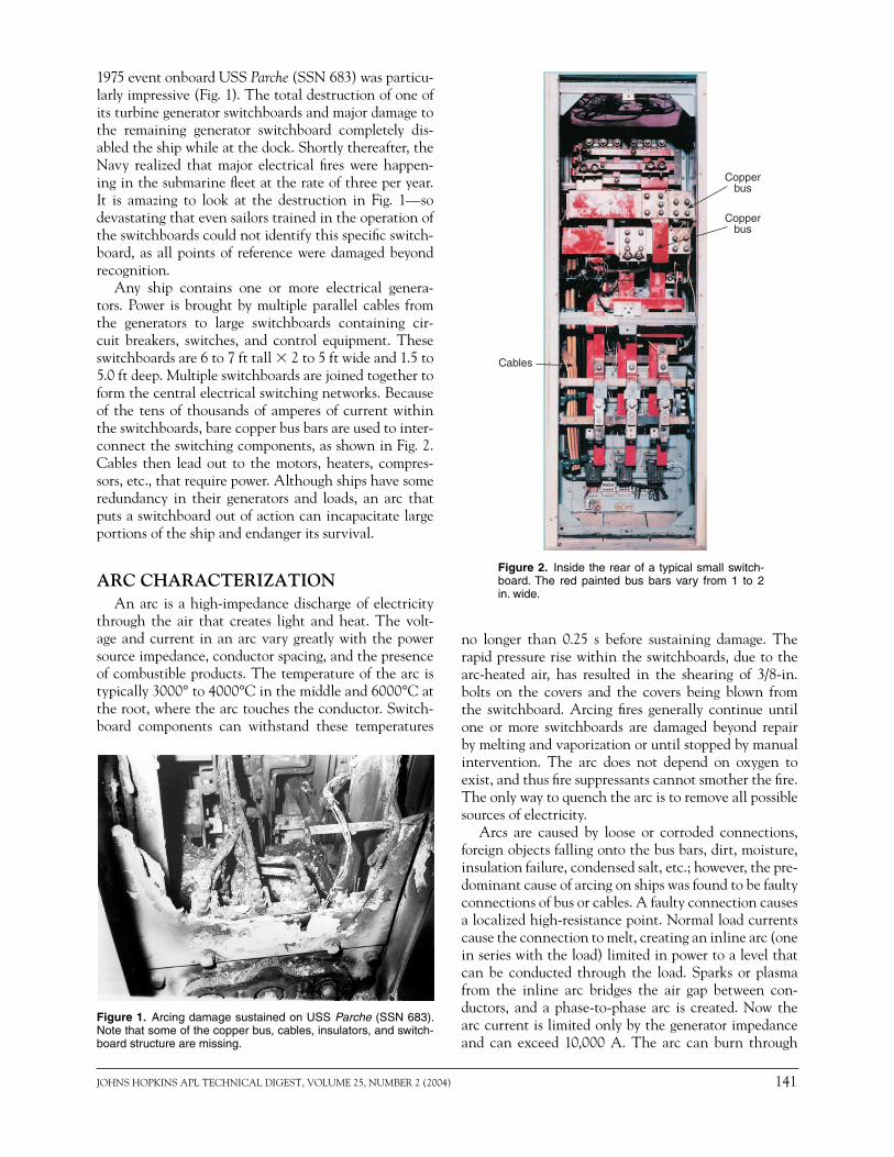
1975 event onboard USS Parche (SSN 683) was particu-larly impressive (Fig. 1). The total destruction of one of its turbine generator switchboards and major damage to the remaining generator switchboard completely dis-abled the ship while at the dock. Shortly thereafter, the Navy realized that major electrical fi res were happen-ing in the submarine fl eet at the rate of three per year. It is amazing to look at the destruction in Fig. 1—so devastating that even sailors trained in the operation of the switchboards could not identify this specifi c switch-board, as all points of reference were damaged beyond recognition.
Any ship contains one or more electrical genera-tors. Power is brought by multiple parallel cables from the generators to large switchboards containing cir-cuit breakers, switches, and control equipment. These switchboards are 6 to 7 ft tall � 2 to 5 ft wide and 1.5 to 5.0 ft deep. Multiple switchboards are joined together to form the central electrical switching networks. Because of the tens of thousands of amperes of current within the switchboards, bare copper bus bars are used to inter-connect the switching components, as shown in Fig. 2. Cables then lead out to the motors, heaters, compres-sors, etc., that require power. Although ships have some redundancy in their generators and loads, an arc that puts a switchboard out of action can incapacitate large portions of the ship and endanger its survival.
ARC CHARACTERIZATIONAn arc is a high-impedance discharge of electricity
through the air that creates light and heat. The volt-age and current in an arc vary greatly with the power source impedance, conductor spacing, and the presence of combustible products. The temperature of the arc is typically 3000° to 4000°C in the middle and 6000°C at the root, where the arc touches the conductor. Switch-board components can withstand these temperatures
no longer than 0.25 s before sustaining damage. The rapid pressure rise within the switchboards, due to the arc-heated air, has resulted in the shearing of 3/8-in. bolts on the covers and the covers being blown from the switchboard. Arcing fi res generally continue until one or more switchboards are damaged beyond repair by melting and vaporization or until stopped by manual intervention. The arc does not depend on oxygen to exist, and thus fi re suppressants cannot smother the fi re. The only way to quench the arc is to remove all possible sources of electricity.
Arcs are caused by loose or corroded connections, foreign objects falling onto the bus bars, dirt, moisture, insulation failure, condensed salt, etc.; however, the pre-dominant cause of arcing on ships was found to be faulty connections of bus or cables. A faulty connection causes a localized high-resistance point. Normal load currents cause the connection to melt, creating an inline arc (one in series with the load) limited in power to a level that can be conducted through the load. Sparks or plasma from the inline arc bridges the air gap between con-ductors, and a phase-to-phase arc is created. Now the arc current is limited only by the generator impedance and can exceed 10,000 A. The arc can burn through
Figure 1. Arcing damage sustained on USS Parche (SSN 683). Note that some of the copper bus, cables, insulators, and switch-board structure are missing.
Copperbus
Copperbus
Cables
Figure 2. Inside the rear of a typical small switch-board. The red painted bus bars vary from 1 to 2 in. wide.

142 JOHNS HOPKINS APL TECHNICAL DIGEST, VOLUME 25, NUMBER 2 (2004)
H. B. LAND III, C. L. EDDINS, AND J. M. KLIMEK
the side of the switchboard enclo-sure in less than 1 s and propagate into adjacent switchboards or eject hot plasma and smoke into manned spaces. Again, arcing usually con-tinues melting down and vaporiz-ing the switchboard materials until manually terminated by an opera-tor many seconds later. It should be noted that the currents in the arcs are low compared with currents through normal loads, and thus the arc is not usually detected by the breakers.
Initially, the Navy worked with the generator and switchboard com-panies to fi nd solutions to the prob-lem. A circuit breaker has the diffi -cult task of discriminating between normal inrush currents and the abnormal currents of an arc, since
over-pressure events. The inside of the switchboard was lined with Marinite, a fi re-resistant structural insulation, to prevent arc involvement with the metal switchboard structure. Connections were designed so that the bus bar involved with the arc could be replaced, as needed, between tests (Fig. 3). Initial testing was performed using 260 VDC at currents between 750 and 10,000 A. The initial goal was to create a reusable environment for generating stable, reproducible arcs similar to those that could occur on the 637 Class submarine. It was quickly determined that any test time over 1 s resulted in too much damage for a rapid turnaround between tests.
The next goal was to investigate all possible arc-sensing techniques and to determine which could best recognize the arc and yet give the best rejection against possible false alarms.1 Data from each sensor under test, arc voltage, and arc current were recorded on an FM tape recorder. Various bandpass optical fi lters, ranging from the infrared (IR) to the ultraviolet (UV), were placed in front of photo detectors to record the optical emissions of the arc. Additional optical tests were performed using a broadband thermopile detector. The fi gure of merit for evaluating optical sensors was the technique with the best ratio of arc signal to that from strong ambient light sources.
Numerous thermocouples were placed within the switchboard to measure temperature. Placement was complicated because thermocouples were vaporized if struck by the arc. Normal type-K thermocouples had too much mass to accurately respond to their short expo-sure to the hot gas. It was found that 0.001-in. platinum versus platinum/rhodium thermocouples would respond rapidly enough to obtain good data. During one test, a thermocouple was vaporized (>1800°C) while a second thermocouple 12 in. away measured room temperature.
Circularelectrodes
APL ArcTest Chamber
108 battery cells
Switch
Figure 3. The Laboratory’s Avery Advanced Technology Development Laboratory Arc Test Facility.
the inrush current to a motor will briefl y exceed 10 times the normal running current. An arc is not a short cir-cuit or “bolted fault” but rather a high-impedance fault with currents similar to those of many normal working loads. Thus, making the breakers respond more quickly to lower currents would result in nuisance tripping of the breakers without increased arc resistance. State-of-the-art current transformers were used to measure the current going into and out of a group of switchboards. Logically, if current is missing it must be taking an unintended path, such as an arc, and the circuit should be opened. However, because of the complexity of the switchboards, size of the current sensors, and accuracy of the current sensors, this solution was not practical.
BASIC RESEARCHIn 1978, an APL staff member met his new neigh-
bor and they were discussing their respective jobs. The neighbor was with the Naval Ship Engineering Center (NAVSEC), which was seeking solutions to the subma-rine arcing problem. NAVSEC was surprised to learn that APL had more than 1200 submarine cells that were used to power a 14-MW arc air heater for the Avery Lab-oratory, then known as the Propulsion Research Labo-ratory (PRL). To work on arc detection schemes, one fi rst needs to be able to reliably and reproducibly create arcs of the needed power. The PRL battery was a good source for reproducing submarine arcs, and the arc air heater gave PRL experience in the creation and control of arcs. Therefore, in May 1978, work on arc detection was initiated at APL.
To begin with, dimensions of typical Navy switch-boards were supplied and APL constructed a test switch-board with special reinforcements to allow it to contain

JOHNS HOPKINS APL TECHNICAL DIGEST, VOLUME 25, NUMBER 2 (2004) 143
ARC FAULT PROTECTION TECHNOLOGY
Therefore, it was concluded that the use of thermocou-ples to detect arcs was not practical since placement of enough thermocouples inside a switchboard to give the needed level of protection would be impractical.
Since arcs regularly blew the doors off switchboards, pressure appeared to be a good candidate for detecting arcs. The APL test switchboard door was fi tted with a rupture disks and breakaway bolts so that dangerous overpressure could be relieved before the enclosure was distorted (Fig. 4). Given that a typical switchboard door is 2880 in2, a pressure rise of only 1 psi would result in a total force of 1.5 tons hitting the door with a rise time of less than 1 s. Without the rupture disk, pressures in the tens of pounds per square inch could be expected from a typical arc event; however, the goal would be to detect the pressure rise well before the onset of any damage.
During this research, various types of pressure sensors were used. At the time, fast-response pressure transduc-ers used small diaphragms and could only detect higher pressures. A custom 0.09-in.-dia. silicon diaphragm pressure transducer was constructed for APL. This unit achieved the desired pressure sensitivity on the bench and, owing to its small size, had a frequency response of >20 kHz. But because the diaphragm was made from sili-con, it became a better photosensor than pressure sensor during the arc tests, and light baffl es had to be added to obtain meaningful data. It was found that 0.5 in. of water, or 0.002 psi, was the optimum detection thresh-old for pressure detection of an arc. While pressure had reasonable discrimination from background signals and thus was a very promising phenomenon to monitor, our custom sensor (Fig. 5) did not have adequate long-term stability, and no mass-produced sensor could be found to achieve the needed sensitivity, response time, and long-term stability.
Extensive analysis was performed on the current and voltage traces from the APL arc tests to look for unique characteristics of the arc. After examination of the large motors and inductive loads on the ship, it was deter-mined that discrimination between the conductive signals from the arc and the background electrical sig-nals from normal loads would be diffi cult. In addition, since electrical signals readily propagate down the bus and cables, it would be impos-sible to isolate the location of the arc to any specifi c switchboard. The use of these parameters to detect arcs was therefore discarded.
As a part of pressure measure-ment, sound from the arc was recorded with a microphone having a 50-kHz response and a wide dynamic range. Sounds of more than 140 dB were recorded 10 ft
Vent
Navyswitchboard
Rupture disk
Breaker
BreakerBreaker
Figure 4. The APL arc test switchboard on the left is shown with the cover on and an aluminum rupture disk on the lower portion of the door. The front of a typical medium-sized Navy switchboard with breakers is shown on the right.
Prototypepressuresensor
Prototypephotosensor
Figure 5. The APL prototype sensors.
from the open switchboard door. However, in the early 1980s, digital signal processing chips did not exist to allow rapid online signal analysis, so there was no way to discriminate the arc sounds from other shipboard sounds in real time and this concept was discarded.
Most of the arcing tests were recorded on 16-mm fi lm using a Fastex camera operating at 4000–5000 frames per second. These fi lms were then examined one frame at a time, and the information was combined with physical damage data to help understand the motion of the arc. This examination revealed that while the core
144 JOHNS HOPKINS APL TECHNICAL DIGEST, VOLUME 25, NUMBER 2 (2004)
H. B. LAND III, C. L. EDDINS, AND J. M. KLIMEK
light from the plasma was intense enough to overexpose the fi lm, it was a very localized event. This confi rmed the localized behavior exhibited by the thermocouples.
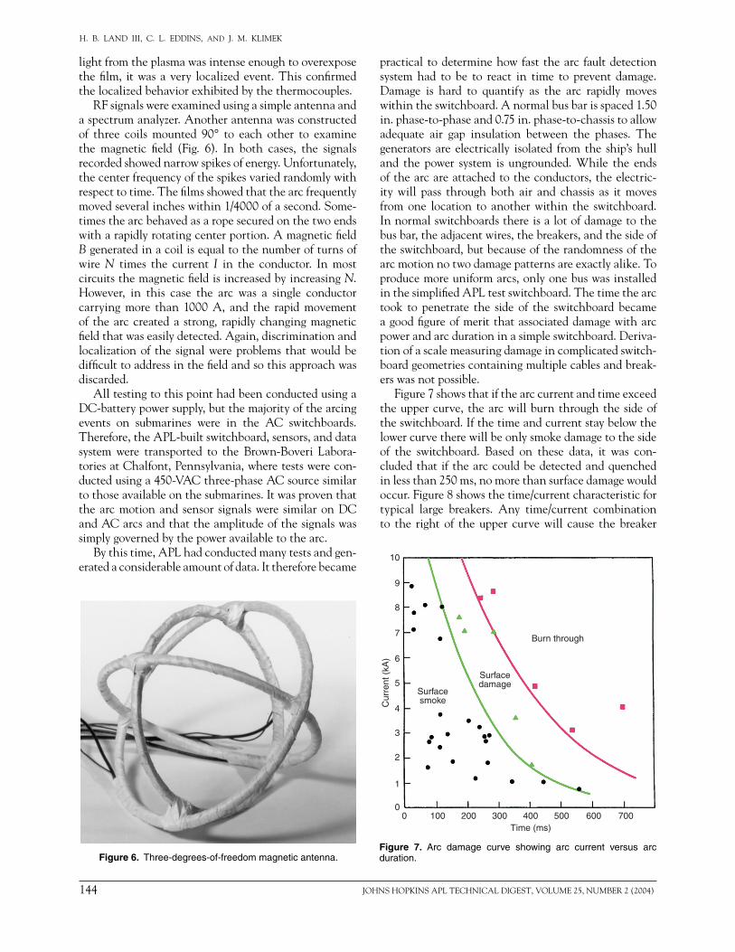
RF signals were examined using a simple antenna and a spectrum analyzer. Another antenna was constructed of three coils mounted 90° to each other to examine the magnetic fi eld (Fig. 6). In both cases, the signals recorded showed narrow spikes of energy. Unfortunately, the center frequency of the spikes varied randomly with respect to time. The fi lms showed that the arc frequently moved several inches within 1/4000 of a second. Some-times the arc behaved as a rope secured on the two ends with a rapidly rotating center portion. A magnetic fi eld B generated in a coil is equal to the number of turns of wire N times the current I in the conductor. In most circuits the magnetic fi eld is increased by increasing N. However, in this case the arc was a single conductor carrying more than 1000 A, and the rapid movement of the arc created a strong, rapidly changing magnetic fi eld that was easily detected. Again, discrimination and localization of the signal were problems that would be diffi cult to address in the fi eld and so this approach was discarded.
All testing to this point had been conducted using a DC-battery power supply, but the majority of the arcing events on submarines were in the AC switchboards. Therefore, the APL-built switchboard, sensors, and data system were transported to the Brown-Boveri Labora-tories at Chalfont, Pennsylvania, where tests were con-ducted using a 450-VAC three-phase AC source similar to those available on the submarines. It was proven that the arc motion and sensor signals were similar on DC and AC arcs and that the amplitude of the signals was simply governed by the power available to the arc.
By this time, APL had conducted many tests and gen-erated a considerable amount of data. It therefore became
practical to determine how fast the arc fault detection system had to be to react in time to prevent damage. Damage is hard to quantify as the arc rapidly moves within the switchboard. A normal bus bar is spaced 1.50 in. phase-to-phase and 0.75 in. phase-to-chassis to allow adequate air gap insulation between the phases. The generators are electrically isolated from the ship’s hull and the power system is ungrounded. While the ends of the arc are attached to the conductors, the electric-ity will pass through both air and chassis as it moves from one location to another within the switchboard. In normal switchboards there is a lot of damage to the bus bar, the adjacent wires, the breakers, and the side of the switchboard, but because of the randomness of the arc motion no two damage patterns are exactly alike. To produce more uniform arcs, only one bus was installed in the simplifi ed APL test switchboard. The time the arc took to penetrate the side of the switchboard became a good fi gure of merit that associated damage with arc power and arc duration in a simple switchboard. Deriva-tion of a scale measuring damage in complicated switch-board geometries containing multiple cables and break-ers was not possible.
Figure 7 shows that if the arc current and time exceed the upper curve, the arc will burn through the side of the switchboard. If the time and current stay below the lower curve there will be only smoke damage to the side of the switchboard. Based on these data, it was con-cluded that if the arc could be detected and quenched in less than 250 ms, no more than surface damage would occur. Figure 8 shows the time/current characteristic for typical large breakers. Any time/current combination to the right of the upper curve will cause the breaker
Figure 6. Three-degrees-of-freedom magnetic antenna.
7006005004003002001000Time (ms)
10
9
8
7
6
5
4
3
2
1
0
Cur
rent
(kA
)
Burn through
Surfacedamage
Surfacesmoke
Figure 7. Arc damage curve showing arc current versus arc duration.

JOHNS HOPKINS APL TECHNICAL DIGEST, VOLUME 25, NUMBER 2 (2004) 145
ARC FAULT PROTECTION TECHNOLOGY
to automatically open. The arc burn-through curve is plotted on the same scale. Any time/current combina-tion between the two curves will cause gross damage to the switchboard without opening the breaker. The fi nal determination was that arcs of 750 A must be detected and quenched in less than 250 ms and that larger arcs must be quenched in less than 90 ms.
EVOLUTION
Sensor Development It was found that ambient events on the submarine
that could create strong lights could not create pressures and vice versa. Therefore, the decision was made to use light and pressure as orthogonal signals to uniquely detect an arc. APL worked with United Detector Tech-nology to develop a photosensor that contained an integral narrowband UV fi lter centered at 325 nm. The resultant photosensor could detect the copper emis-sion line from the arc while ignoring other strong light sources. Four light emitting diodes (LEDs) were included on the substrate with the photodiode chip. Under com-mand of the built-in test (BIT), the light from the LEDs was bounced from the back of the photosensor lens into the photodiode, allowing for end-to-end testing. Each switchboard would contain two to six photosensors to ensure that at least one could see any location at which an arc could occur.
APL worked with World Magnetics Corp. to develop a sensor based on a small pressure switch that activated at 0.5 in. of water column pressure. Since the absolute pressure on a submarine can vary greatly with changes in ventilation and submergence, the Arc Fault Detection (AFD) system was chosen to look at the pressure difference between the inside and outside of the switchboard. The relatively slow, normal pressure changes in the submarine would be equalized with the inside of the switchboard through the switch-board louvers. The pressure shock wave from the arc would not escape the switchboard without being regis-tered by the AFD pressure sensor. An electrical switch was included parallel to the pressure switch for use by the BIT processor in the control unit. Under manual or program control, the BIT processor in the centrally located control unit can activate the BIT feature in the photo- and pressure sensors and perform an end-to-end test of the system. Two pressure switches were packaged in parallel into one housing for redundancy. Proper positioning of the sensors within the switch-board was based on APL’s understanding of arc behav-ior and is very important to the optimum operation of the system.
The fi nal design required that the narrowband UV signal exceed a given threshold for a specifi c amount of time, that the pressure inside the switchboard be higher than the pressure outside by at least 0.5 in. of water for a specifi c time, and that the proper phasing of the two signals exist before deciding that a real arc was present and was opening the proper breakers.
System DevelopmentIn May 1982, another severe arc fault casualty
occurred on a submarine. The fault began inside a large molded case breaker, propagated into the bus bar behind the breaker, gained strength, and penetrated the adja-cent switchboards. It then set the hull insulation on fi re before an operator could manually trip the breaker. This event increased APL’s interest in the small AFD effort.
With most of the answers in hand from the arc detection sensor research, in 1982 the Navy directed APL to move from sensor design to the design of a full AFD system. The design was to focus on four stringent mandatory guidelines and one desired guideline. Fur-thermore, APL was to design the system to meet full military specifi cations:
1. Opening of breakers caused by either false detection of an arc or from any failure of the AFD system or its components was not allowed, i.e., no single point failure could inadvertently cause a false breaker trip.
2. Switchboard burn-through was to be prevented by clearing all faults above 750 A in less than 0.25 s. This mandated fully automatic operation and no manual intervention.
106105104103102
Current (A)
10,000
1000
100
10
1
0.1
0.01
Tim
e (s
)
Arcing burn-throughcurve based on
experimental data
Time/currentcharacteristic
curves forcircuit breaker
Figure 8. Arc damage curve overlaid on the breaker response time curve.

146 JOHNS HOPKINS APL TECHNICAL DIGEST, VOLUME 25, NUMBER 2 (2004)
H. B. LAND III, C. L. EDDINS, AND J. M. KLIMEK
3. The extent of shutdown of the ship’s electrical power was to be minimized. This required the AFD system to be able to localize the arc and activate the mini-mum number of breakers to quench the arc. The ship was divided into independent zones of protection, and each AFD system was to protect and isolate only one zone.
4. Major switchboard damage that could result from phase-to-phase arcing was to be prevented. This con-fi ned the AFD protection to the bus bar enclosure and not to the breakers.
5. Assurance was needed that the system would be online and fully functional at all times by the use of the BIT.
APL completed fabrication of the Engineering Design Model AFD system in December 1982. AC arc valida-tion tests were successfully conducted at the Brown-Boveri Laboratories to confi rm the system’s perfor-mance. Additional tests were conducted to qualify the system for shipboard shock (MIL-S-901C) and vibration (MIL-STD-167).
APL next constructed a preproduction prototype for a formal Navy Technical Evaluation. This version of the AFD system received additional testing for electro-magnetic interference and radio-frequency interference (MIL-SPEC-461, EMI/RFI), water spray, and environ-mental temperature. A chassis containing only one AFD zone was installed on USS L. Mendel Rivers (SSN 686) in November 1984. A data system was installed to record details of system operation. By January 1986, 7600 h of operation had been accumulated on the system, and it was considered an unqualifi ed success.
In mid-1984, APL began the design and construc-tion of a full four-zone AFD system for Operational Evaluation. Installation of the system on USS Sea Devil (SSN 664) was completed in December 1985. During this period, APL hired outside companies to perform a formal sneak circuit analysis and a failure modes effects and criticality analysis. After the Laboratory addressed a couple of issues, the system was certifi ed to have no single point failures that could inadvertently cause a breaker to trip. The Operational Evaluation concluded in October 1986 with a few recommendations for improvements. After incorporation of the recommendations, the system was approved for full production in May 1987.
Until this time, most of the AFD design work had proceeded relatively slowly because of modest levels of funding. The system was perceived by some in the Navy to be applicable only to older submarines. The lead shipyard for 688 Class design had stated that the arcing problem was due to the old design and poor main-tenance in the older ships. On 15 September 1986, a major arc fault occurred on USS Louisville (SSN 724) while it was still in the shipyard, and alpha sea trials had to be postponed. Three more arcing casualties occurred
in the submarine fl eet in rapid succession. In November 1987, an arcing event destroyed several switchboards on USS Florida (SSBN 728), requiring it to leave patrol for repairs. Now that arcing events had happened on both 688 and Ohio (Trident) Class submarines, the Navy changed the Laboratory’s focus from the older to the newer vessels, increased the level of effort, and halted procurement of the AFD system for the SSBN 616/640 and SSN 637 Class submarines.
Modifi cationsSwitchboards in the newer submarines contained
differences that required additional testing of the AFD system and changes to the sensor sensitivities. Pressure sensitivity had to be lowered to 0.25 in. of water. While the arc can generate a substantial average pressure, the violent motion of the arc causes considerable oscillation in the pressure at any given location, causing the pres-sure switch to oscillate between being satisfi ed and not satisfi ed. In the older, smaller switchboards, the valleys in the pressure stayed above 0.5 in. In the newer, larger switchboards, the pressure rose more slowly and the oscillations were more pronounced. This reduced our pressure response time below the target level of 20 ms. A pneumatic pressure rectifi er and fi lter were designed to smooth the pressure perceived by the pressure switch (Fig. 9).
The newer submarines had many more switchboards per zone, and the AFD electronics had to be expanded accordingly. Each class of ship required its own system-level design. The Navy decided that the procurement would be advertised as “build-to-print” in Commerce Business Daily, and APL moved to upgrade all drawings to full level 3 compliance. In addition to the mechani-cal drawings, specifi cations were written for calibration, assembly, and testing at both the component and system level. Technical manuals were written describing opera-tion and troubleshooting of the system.
APL had conducted more than 2000 arcing tests from a few kilowatts up to several megawatts to help under-stand the arcing phenomena and to test the sensors and systems. Many of these arcs had been recorded with very high speed fi lm and then reviewed frame by frame for additional insight. Based on this experience, APL
Submarine AFDpressure sensor
Pressure sensor connector base
Figure 9. Pressure sensor.

JOHNS HOPKINS APL TECHNICAL DIGEST, VOLUME 25, NUMBER 2 (2004) 147
ARC FAULT PROTECTION TECHNOLOGY
became the lead investigator for most of the arc casual-ties that occurred on ships since 1980. The Laboratory’s expertise was also used by the National Transportation Safety Board to assist in the investigation of an electri-cal fi re on a large Alaskan ferry.
In mid-1988, APL was funded to assist in the design of the switchboards for the new SSN 21, Sea Wolf Class submarine. The Laboratory contributed to making the switchboards more arc resistant and designing an AFD system for SSN 21. During this time APL also designed and built prototype fi eld test equipment for the AFD system. This test equipment supplied a calibrated level of UV light and a calibrated pressure for testing the AFD sensors. Level 3 drawings for the fi eld test equip-ment were supplied to the Navy for their procurement.
ProductionIn August 1989, the Navy awarded a contract to Pow-
ertronic Systems Inc. of New Orleans to begin produc-tion of the Trident AFD system. In 1990 installations of the production AFD systems began. Over the next few years, AFD systems were built and installed on all 688 and Ohio Class submarines.
Problems were initially experienced in the accuracy of the AFD wiring being installed by the shipyard, and APL was approached for a solution. The Laboratory designed a cable-testing scheme based on a commer-cial cable tester, more than 30 connector adapters, and software to perform end-to-end tests of the cables. This proved successful, and APL was tasked to produce simi-lar cable test systems for each class of submarine.
In May 1993, an arcing fault occurred on USS Okla-homa City (SSN 723). This was the fi rst arc fault to occur in an AFD-protected ship. The system reacted so quickly that the incident was limited to smoke damage. The ship’s force fi xed the cause of the arc, removed the surface smoke deposits, and returned the switchboard to service while remaining at sea. Since that time, the submarine AFD system is credited with correctly iden-tifying and quenching nine arcing events and directly saving two lives. In more than 700 ship years (>3000 system years) of service the system has never caused a false breaker trip.
Improvements for Virginia Class SubmarinesIn 1994, APL evaluated the Virginia Class (formally
NSSN) switchboards for arc susceptibility and was sub-sequently funded to begin a Virginia Class AFD system design. By this time, the Navy had accepted the philoso-phy of the AFD system and was pleased with its results. However, while the system reacted quickly enough to greatly minimize damage, it was still an AFD system and thus did not prevent all damage. The Navy wanted improvements. For the Virginia Class design, the Navy asked APL to investigate methods of predicting the arc and furnishing an alarm before it occurred. In addition,
the Navy required that the new capability be added without raising the cost of the production hardware.
As sensitivity of the AFD system is increased, the risk of false alarms is also increased. Since the Navy had become more comfortable with the system, they asked what could be done to make it respond more quickly to the arc and stated that they were now will-ing to accept a bit more risk. The photosensor was rede-signed to increase sensitivity and to allow it to operate from the refl ected arc rather than just from direct line of sight. As part of this modifi cation, the narrowband UV fi lter was removed and a special lens coating was developed. This coating transmitted the arc light while permitting the light from the BIT LEDs to be refl ected back into the detector. Figure 10 shows the narrowband UV photosensor atop a connector base and a wideband photosensor. In each case, the detection of the proper wavelength, amplitude, and timing of the light results in the opening of the breakers. Each sensor contains LEDs for BIT operation. This redesign reduced the cost of each photosensor from $2500 to less than $600 and increased the operational life of the sensors, resulting in a fl eet-wide life-cycle cost savings of $55 million. It also resulted in major production cost savings that could be used to add the arc prediction capability to the Virginia Class AFD system.
All Navy electrical fi re data from the previous 20 years was examined in detail by APL, NAVSEA, and Science Applications International Corp. (SAIC).2 It was concluded that 60 to 80% of all arcing faults origi-nated as inline arcs caused by faulty connections. APL moved into a testing program to understand how faulty connections develop into arcs and to develop arc pre-diction sensors. As a part of the APL casualty analysis, samples of overheated connections were obtained from the fi eld. A good connection requires clean surfaces and good pressure to create an airtight mating of the sur-faces.3 If the connection becomes loose, its resistance increases and oxidation and corrosion attack the mating surfaces, thus increasing the resistance even more. With the application of current, the connection heats, which accelerates oxidation and further raises resistance. Even-tually, the resistance reaches a point at which the con-nection melts, creating an arc.
Connectorbase
Narrowband photosensor
Newer widebandsubmarine
photosensor Newest widebandphotosensor forsurface ships
Figure 10. AFD photosensors.

148 JOHNS HOPKINS APL TECHNICAL DIGEST, VOLUME 25, NUMBER 2 (2004)
H. B. LAND III, C. L. EDDINS, AND J. M. KLIMEK
Extensive testing was undertaken at APL to deter-mine how an event progresses. Tests were performed with wires from 4 AWG (0.23-in. dia.) to 400 MCM (0.73-in. dia.). Curves were created from the data which showed the correlation between the torque placed on the connection bolt and the temperature rise of the connection. Cycling the power on and off caused the temperature to go even higher with each cycle until the joint failed completely.
Thermal imaging cameras are used by the Navy and commercial power installations to help identify over-heated connections before they create a problem. Unfor-tunately, these tests must be performed by applying elec-trical power to the switchboard, and power needs to be consumed by each load at the time of the test to be truly effective. The covers of the switchboard must be open during the test, creating a safety issue. Typically, less than half of the connections are visible from outside the switchboard (Fig. 2). Because of costs, thermal imaging is performed only periodically and is not a continuous reading of connection quality. APL testing showed that a connection can go from good to bad within a few days. Therefore, while thermal imaging programs are useful, they are not a complete solution. In fact, a cable with thermally damaged insulation was found on a subma-rine 2 days after the switchboard had successfully passed thermal imaging tests.
Since a faulty connection is hot, IR detectors are a natural choice. APL surveyed 204 different IR detectors from 15 different technologies. The specifi cations of 69 detector assemblies and systems were examined. Detec-tors using lead sulfi de, lead selenide, indium arsenide, pyroelectric, and thermopile technologies were pur-chased, assembled into sensors, and tested.4
The emissivity of the switchboard components varies with age, and the energy captured by a detector falls off with the cosine of the angle. An IR detector reads a single value related to the average temperature of its total fi eld of view. This means that a single hot 3/8-in. bolt on a cool background would give the same detector output as if the entire fi eld of view was at a warm tem-perature. The ideal solutions would be to have one IR detector per possible hot spot or an IR imaging system with a resolution equal to the minimum hot spot size.
One concept required the use of IR optical fi ber detec-tors to allow sensing the temperature at an individual joint. The cost of $300 per meter for IR fi ber caused this concept to fall by the wayside. Low-cost silicon imaging arrays did not have enough sensitivity in the IR range to be useful.
Thermopile detectors were the most promising because of their IR sensitivity, small size, low cost, and long-term stability. Amplifi cation and ambient temperature compensation were added to the thermo-pile, creating a complete, small (1.5-in.-long � 0.85-in.-dia.) sensor. This sensor performed well and costs
were projected to be less than $100 each in production. The concept was later discarded because of the exces-sive amount of wiring required to accomplish the total task. Similarly, the use of inexpensive contact tem-perature measurement sensors, such as the AD590, was examined. This concept was also discarded because of excessive wiring.
The best IR cameras of the time used a single high-quality IR detector and two mirrors to scan the image in the x and y directions. These units produced good visual quality and calibrated results, but they were too large, complicated, delicate, and expensive for this applica-tion. The IR focal plane array cameras of the time were smaller and more rugged, but were even more expensive and not quantitative enough for the task.
APL conceived of two different ways of using a single thermopile to scan the inside of a switchboard. The fi rst built on the fact that light rays are slightly bent as they pass through an optical wedge. Two concentri-cally aligned counter-rotating optical wedges were used to steer the IR energy onto the single detector. Plotting the intensity of the output of the detector with position produces a gray-scale image of the scene being scanned. While the optical wedges would have to be custom man-ufactured, this concept held the promise of being a rela-tively small and rugged pseudo-IR imaging system.
In the second concept, an IR fi lter was added to a thermopile and installed in a housing that looked much like a gun barrel inside a turret. As the turret was rotated, the gun barrel oscillated 45° up and down. This process continued until the entire image was scanned. Gearing was used so that one motor could control both the rotation and elevation of the detector view. Approx-imately 60 min were required to scan a 90° cone of view and produce an IR image on a PC. The turret scanner proved to be small, rugged, and relatively inexpensive. The photographic agreement between the turret scan-ner and the commercial IR imaging system was good. Unfortunately, the switchboard did not have enough room to position enough sensors for full coverage of all of the connections, and this concept was discarded.
Continuous Thermal MonitoringSmoke and fumes are emitted from overheated con-
nections, and as such were investigated as possible ave-nues for detection of a hot connection. Commercial gas detectors based on semiconductors and heated beads were assessed. While these detected the outgassing from the overheated connections, they also responded to paint fumes, diesel generator fumes, and other gases that are likely to be present on a ship. These types of units experienced problems with long-term stability and calibration and thus were not suitable for long-term unattended operation in a power plant. Photoelectric smoke detectors were also examined, found to have simi-lar problems, and thus discarded.

JOHNS HOPKINS APL TECHNICAL DIGEST, VOLUME 25, NUMBER 2 (2004) 149
ARC FAULT PROTECTION TECHNOLOGY
In another investigation, a sensor was designed using a commercially available radioactive ionization cham-ber. Ionization chambers use a small radioactive source (less than 1 �Ci of americium-241) to ionize a fi eld between two polarized electrodes. This creates a small baseline fl ow of electrons between the plates. When properly sized particles enter the fi eld they soak up elec-trons and the fl ow of current is reduced. The change in current is proportional to the number of particles. Since the number of particles emitted by the overheated con-nection is proportional to temperature, it was possible to calibrate the ionization signal so that it was proportional to the temperature of the connection. Thus the Ther-mal Ionization Detector (TID) was produced.
For a moment consider the simple mercury thermom-eter that was used to take a person’s temperature 20 years ago. Actually, the thermometer measured the expansion of mercury in a confi ned space, but the confi ned space was calibrated such that it was related to temperature. In additional, the thermometer only measured human body temperature relatively accurately when it was prop-erly placed in the mouth and under the tongue. If the thermometer was placed under the armpit or in another orifi ce the temperature measured was not the body tem-perature because of instrument application error.
Similarly, the TID was calibrated to become a tem-perature sensor. If the distance between the TID and the hot connection was known, then the TID output would represent the temperature of the overheated con-nection. If the distance and relative position were not known, then there would be an error in the absolute temperature measurement. Errors could also creep into the measurement because of convection and duration of the heating. However, in the switchboard application one merely needs to know that a connection is faulty well before it actually fails, and thus absolute accuracy is not required. Testing and calibrations resulted in a setpoint that correctly identifi ed if any connection within the switchboard reached a temperature between 150° and 300°C, regardless of the connection’s position within the switchboard. While this is a wide tempera-ture spread, it is signifi cantly below the 1083°C needed to melt copper and thus it will give a useful alarm well before the joint fails. In 2001, the TID was awarded a patent.5 Two versions of the TID were created, a full MIL-SPEC one with a digital output for the subma-rine system and later one with an analog output for the nuclear aircraft carrier (CVN) system (Fig. 11).
The TID sensor allowed continuous monitoring of the switchboard for faulty connections and was a major step forward from the intermittent protection given by thermal imaging. Thus was born the APL Arc Fault Detection and Continuous Thermal Monitoring (AFD/CTM) system. This new system met the Navy’s require-ments for arc fault prediction and quicker response to arcing events, and yet came in under the cost of previous
AFD hardware. All four of the Virginia Class subma-rines produced have AFD/CTM systems and all future submarines are slated for similar installations.
For a long time, only the submarine community was interested in arcing protection. Several years of propos-als to the carrier community had produced no results. In 1996, the Navy realized that they were having three arcing faults per year in a carrier fl eet of only nine, so APL was asked to join a team looking into the switch-board arcing problem. After some study, the Laboratory concluded that the arcing problems on the CVNs were similar to those on the submarines and were amenable to a similar solution.
AFD Protection for Nuclear Aircraft CarriersWhile submarines have 15 to 30 switchboards per
ship, the CVN has 80 that are considered critical. Since the submarine was designed using full MIL-SPEC components, the AFD hardware costs approximately $35,000 per protected switchboard. The submarine system used metal sensors that required the installation of heavy mounting brackets to pass the shock tests. It was designed with a star-type wiring system of unique wires from each sensor to the control unit. The wiring and brackets combined to make the installation cost as much as the hardware. Still, fi res were critical enough on submarines to justify this level of system costs.
With their greater number of switchboards and their lower concern for fi res, the CVN community would not absorb the projected cost to protect a CVN with the submarine hardware. At about this point, the DoD put forward its new COTS (commercial off-the-shelf) design philosophy. The confl uence of changes to the Navy design guidelines and advances in technology, as pre-sented below, allowed APL to propose methods of rede-signing the system to reduce the cost of the hardware to approximately 20% of that of the submarine system.
Submarine TIDon its connector base Newer plastic TID
for surface ships
Figure 11. Thermal Ionization Detectors (TIDs).

150 JOHNS HOPKINS APL TECHNICAL DIGEST, VOLUME 25, NUMBER 2 (2004)
H. B. LAND III, C. L. EDDINS, AND J. M. KLIMEK
• When the original AFD system was designed in the early 1980s all hardware had to be MIL-SPEC and this added considerable cost. In the 1990s the Navy enacted the COTS thrust that allowed reduction in the cost of components. A MIL-SPEC optical iso-lator cost $26, whereas the consumer-grade equiva-lent cost $1. The COTS thrust allowed APL to move from a custom-welded control unit chassis and card cage to a commercial spray-tight box made to the National Electrical Manufacturing Association (NEMA) standard and a PC-104 computer bus.
• In the 1980s most sensor and computer systems were wired in the star confi guration discussed above. In the 1990s networking became accepted. The move from a star wiring scheme to a daisy chain network wiring confi guration greatly reduced installation costs.
• In the 1980s the way to design sensors to meet all MIL-SPEC requirements was to use metal. The 1990s brought technology that allowed a transi-tion from metal to shielded plastic. This transition reduced the size and weight of the sensors. Note that the plastic sensor, unlike a metal sensor, is self-insulating.
• With the use of lighter insulated sensors, double-sided adhesive tape was proposed for mounting them. This eliminated the need for heavy brackets and most drilling within the switchboards.
• The use of a microcontroller sensor multiplexer within the switchboard distributed processing out onto the network and reduced the computing load on the central control unit.
• In the 1980s most integrated circuits were dual inline packages. These circuits were large and required holes through the printed circuit board. In the 1990s smaller surface-mount components became readily available. The use of these surface-mount compo-nents throughout the system saved space, weight, and cost over the through-hole components in the submarine system.
• While a custom motherboard was designed for the control unit, the use of a PC-104 backplane allowed the inexpensive addition of input and output con-nections and a COTS rugged terminal for the human–machine interface.
• In the 1980s microprocessors were new and un-proven, and thus the Navy would not allow their use on systems related to reactors. In the 1990s the Navy accepted the use of microprocessors to replace large quantities of discrete logic chips.
• The surface ship switchboards had bigger louvers, which resulted in decreased pressure rises compared with previous experiences. The choices were to retain the use of two parameters for arc detection by redesign of the pressure transducer to meet this new environment or by switching to the use of only the
photosensor to detect arcs. By this time, the Navy had enough confi dence in the AFD technology that they decided to drop the requirement for pressure sensing in surface ship applications. The Navy concurred with these changes to the design
philosophy, and use of the AFD/CTM system for CVNs began. Although COTS allowed the procurement of less expensive parts, the Navy still required that the system meet all Navy shipboard environmental requirements for shock, vibration, spray, temperature, EMI/RFI, etc., and this presented challenges. One of the most amaz-ing challenges met was when APL obtained certifi cation from NAVSEA 08 (Nuclear Department), allowing the use of double sticky tape to install AFD/CTM compo-nents inside nuclear switchboards. APL exceeded the design goal and reduced the cost of the hardware from $35,000 per protected switchboard to $3,500 per switch-board. The addition of the COTS terminal allowed an expanded human –machine interface as compared to the lights and switches on the submarine system. The fi rst AFD/CVN installation occurred in 1998 on USS George Washington (CVN 73).
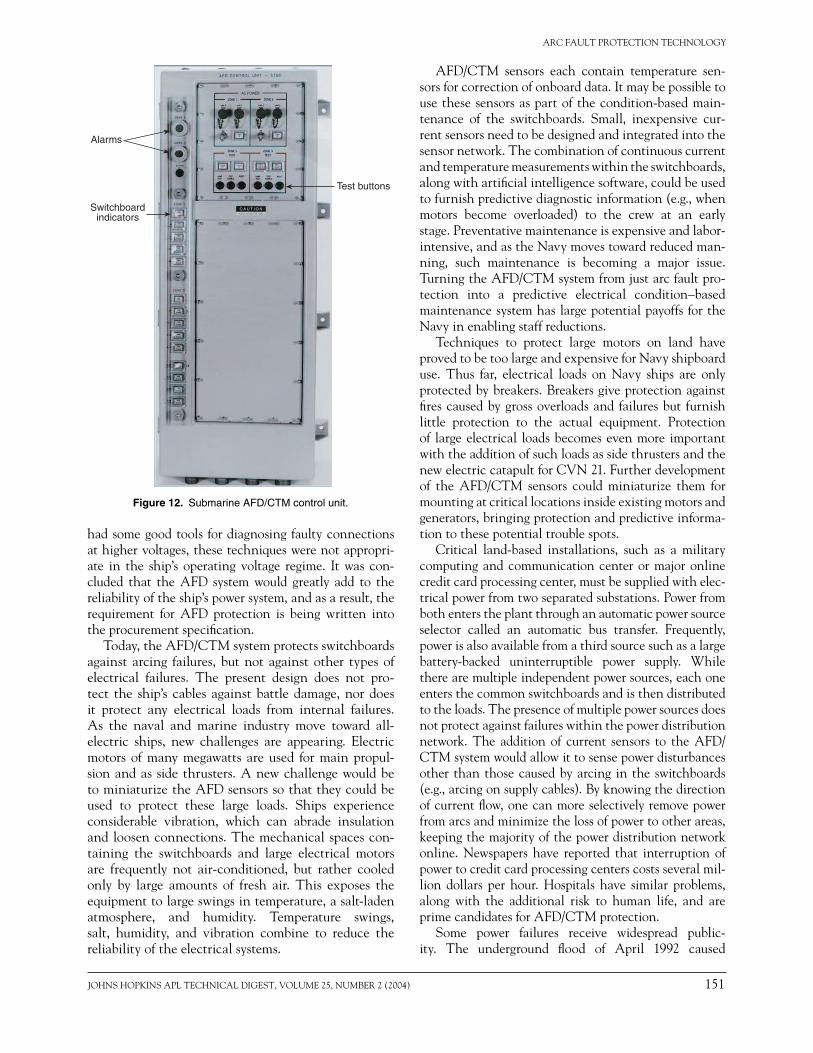
The submarine control unit could protect up to 15 switchboards per central control unit and up to 2 zones of protection. (A zone of protection was defi ned as the smallest number of switchboards from which power would be removed in a group for arc protection.) All operator input was via switches; communication to the operator was via LEDs and legend lights. This chassis was hardened and mounted directly to the ship’s bulk-head (Fig. 12). The surface ship control unit was a lighter commercial stainless steel chassis with a full alpha-numeric display and keyboard for bidirectional operator communication. To meet the shock and vibration speci-fi cations, the chassis was mounted on the coiled steel rope shock absorbers.
FUTURE WORKA new type of power distribution architecture, the
Integrated Power System (IPS), was proposed for the next-generation destroyer (DDX). The IPS system focused on the integration of electric propulsion into an all-electric ship. With the design of conventional ships, the screw (propeller), shaft, and drive unit (steam turbine, gas turbine, or diesel engine) are fi rst placed in alignment and then all other elements are installed around the propulsion items. With electric drive, the generation of the power and the screw do not have to be coupled by a shaft and so they no longer drive the layout of the ship. However, the use of electric propul-sion greatly increases the amount of electricity that must be generated and distributed and increases the risk of electrical fi res. In 2000, APL evaluated the IPS and found that it was as susceptible to arcing faults as any other electrical distribution system. Although industry
JOHNS HOPKINS APL TECHNICAL DIGEST, VOLUME 25, NUMBER 2 (2004) 151
ARC FAULT PROTECTION TECHNOLOGY
Switchboardindicators
Test buttons
Alarms
Figure 12. Submarine AFD/CTM control unit.
had some good tools for diagnosing faulty connections at higher voltages, these techniques were not appropri-ate in the ship’s operating voltage regime. It was con-cluded that the AFD system would greatly add to the reliability of the ship’s power system, and as a result, the requirement for AFD protection is being written into the procurement specifi cation.
Today, the AFD/CTM system protects switchboards against arcing failures, but not against other types of electrical failures. The present design does not pro-tect the ship’s cables against battle damage, nor does it protect any electrical loads from internal failures. As the naval and marine industry move toward all-electric ships, new challenges are appearing. Electric motors of many megawatts are used for main propul-sion and as side thrusters. A new challenge would be to miniaturize the AFD sensors so that they could be used to protect these large loads. Ships experience considerable vibration, which can abrade insulation and loosen connections. The mechanical spaces con-taining the switchboards and large electrical motors are frequently not air-conditioned, but rather cooled only by large amounts of fresh air. This exposes the equipment to large swings in temperature, a salt-laden atmosphere, and humidity. Temperature swings, salt, humidity, and vibration combine to reduce the reliability of the electrical systems.
AFD/CTM sensors each contain temperature sen-sors for correction of onboard data. It may be possible to use these sensors as part of the condition-based main-tenance of the switchboards. Small, inexpensive cur-rent sensors need to be designed and integrated into the sensor network. The combination of continuous current and temperature measurements within the switchboards, along with artifi cial intelligence software, could be used to furnish predictive diagnostic information (e.g., when motors become overloaded) to the crew at an early stage. Preventative maintenance is expensive and labor-intensive, and as the Navy moves toward reduced man-ning, such maintenance is becoming a major issue. Turning the AFD/CTM system from just arc fault pro-tection into a predictive electrical condition–based maintenance system has large potential payoffs for the Navy in enabling staff reductions.
Techniques to protect large motors on land have proved to be too large and expensive for Navy shipboard use. Thus far, electrical loads on Navy ships are only protected by breakers. Breakers give protection against fi res caused by gross overloads and failures but furnish little protection to the actual equipment. Protection of large electrical loads becomes even more important with the addition of such loads as side thrusters and the new electric catapult for CVN 21. Further development of the AFD/CTM sensors could miniaturize them for mounting at critical locations inside existing motors and generators, bringing protection and predictive informa-tion to these potential trouble spots.
Critical land-based installations, such as a military computing and communication center or major online credit card processing center, must be supplied with elec-trical power from two separated substations. Power from both enters the plant through an automatic power source selector called an automatic bus transfer. Frequently, power is also available from a third source such as a large battery-backed uninterruptible power supply. While there are multiple independent power sources, each one enters the common switchboards and is then distributed to the loads. The presence of multiple power sources does not protect against failures within the power distribution network. The addition of current sensors to the AFD/CTM system would allow it to sense power disturbances other than those caused by arcing in the switchboards (e.g., arcing on supply cables). By knowing the direction of current fl ow, one can more selectively remove power from arcs and minimize the loss of power to other areas, keeping the majority of the power distribution network online. Newspapers have reported that interruption of power to credit card processing centers costs several mil-lion dollars per hour. Hospitals have similar problems, along with the additional risk to human life, and are prime candidates for AFD/CTM protection.
Some power failures receive widespread public-ity. The underground fl ood of April 1992 caused

152 JOHNS HOPKINS APL TECHNICAL DIGEST, VOLUME 25, NUMBER 2 (2004)
H. B. LAND III, C. L. EDDINS, AND J. M. KLIMEK
electrical damage that darkened the Chicago Loop for several days. In July 1999, electrical failures darkened the Loop again. While the great New York City blackouts of November 1965, July 1977, and August 2003 are well known, many smaller blackouts have affected smaller areas such as Wall Street. Several of these blackouts have been traced back to the failure of switchboard and substation components. While AFD/CTM protection is important for these applications, additional research would have to be done to determine if modifi cations are needed for these higher voltage and power applications and how the technology could best be integrated into these power distribution networks.
For completeness, it should be mentioned that Arc Fault Circuit Interrupter (AFCI) breakers are now avail-able for residential use. These breakers are the follow-on to the familiar Ground Fault Interrupter (GFI) breakers. Both AFCI and GFI breakers are intended to protect homes from the small sputtering arcs caused by compro-mised wire insulation, which can cause house fi res. A sputtering 1- to 2-A arc will release more than enough heat to set carpets, drapes, and wood on fi re. These breakers work by looking for the electrical noise that the arc impresses upon the power line. Unfortunately, motor brushes, light switches, etc., can impress similar noise on the power line and sometimes cause false tipping of the breakers. Although these breakers work well in the residential environment, Square D, a large breaker manufacturer, notes that this technology is not likely to ever work in commercial environments because of the high level of electrical noise and the higher currents in commercial use. While AFCIs are an improvement for residential service, they are not currently applicable to Navy shipboard applications.
CONCLUSIONSAFD has been a collection of many programs over
many years at APL. The earliest systems were designed for nuclear submarines and placed stringent require-ments on both pressure and light signals before trip-ping breakers. The TID was added to the later subma-rine designs to furnish arc fault prediction and prevent damage. With the surface ship systems, the pressure sensors were removed and the photosensors alone were allowed to trip breakers. The TID continues to be used on surface ships.
Clearly, commercial ships need similar arc fault pre-diction and protection. While commercial ships are pri-vately owned and thus public reporting of fi res is rare, there have been several reports of electrical fi res in the cruise ship industry. The latest cruise ships have gone all-electric and contain more than 60 MW of total
power. Hospitals, power plants, Internet server farms, credit card processing facilities, etc., all require high-reliability power, and the expansion of the AFD/CTM technology could fi nd wide use in those applications.
APL took the arc problem from basic research into characterizing arc behavior to sensor research and devel-opment. A complete system was developed around the sensors and integrated into submarine and ship power systems. Level 3 production drawings were created and delivered to the Navy, and systems were mass produced via competitive bids. More than 15,000 photosensors, 4000 pressure sensors, and 175 control units have been built and deployed on each ship of all classes of subma-rines. More than 50 control units and 1700 sensors have been deployed on nuclear aircraft carriers. AFD systems have been credited with saving nine ships and two lives. They are approved by the Navy for connection to all types of power systems including nuclear systems. AFD protection is being planned for all new classes of ships. Although this technology has progressed to the point where it is appropriate for protecting the AC power for commercial ships and critical land-base applications, it presently is a stand-alone capability and work is needed to make it a fully integrated, generalized solution to power quality issues.
REFERENCES 1Land, H. B. III, “Sensing Switchboard Arc Faults,” IEEE Power Eng.
Rev. 27, 18–20 (Apr 2002). 2The Arc Fault Detection/Prevention Enhanced System: An Assessment of
the Continuous Thermal Monitoring (CTM) System Research and Devel-opment Program, Prepared for PEO-SUB-R, NAVSEA, by SAIC, SEA Technology Division, Arlington, VA (Aug 1994).
3Denault, C. L., “Electrical Contact of Bus Bar Joints,” Electric J. (Jul 1933).
4Land, H. B. III, Eddins, C. L., Gauthier L. R. Jr., and Klimek, J. M., “Design of a Sensor to Predict Arcing Faults in Nuclear Switchgear,” IEEE Trans. Nucl. Sci. 50(4) (Aug 2003).
5Land, H. B. III, Eddins, C. L., Gauthier, L. R. Jr., and Klimek, J. M., “Thermal Ionization Detector,” U.S. Patent 6,292,105, Patent & Trade-mark Offi ce, Washington, DC, pp. 1161–1165 (18 Sep 2001).
ACKNOWLEDGMENTS: The sponsorship of this work originated with NAVSEC (6156B) in 1978 and moved to Peter Knowles (NAVSEA-5421) under N. Rivera. Donald Strawser (NAVSEA 05Z44) became the sponsor in 1987 and was the sponsor for the subsequent AFD programs. S. Kurth (NAVSEA 08K) has provided valuable support and interface with the nuclear world throughout the life of the program. R. T. Cusick began the program and was the APL program manager until late 1981, when J. F. George assumed program management. H. B. Land III was the AFD system engineer for the entire program and became the program manager in January 1992. While many at APL contributed to this work, the basic submarine work was signifi cantly affected by the contributions of D. A. Carpenter, K. R. Fowler, J. A. Frantz, S. A. Grand, D. Richards, W. E. Sparrow, and L. C. Witte. L. R. Gauthier was the system engineer for the NSSN design, D. R. Kohler contributed to the IR work, and S. A. Gearheart contributed to the optics design. W. Schneider and D. S. Wenstrand performed detailed electrical design of the CVN control unit and sensor interface module. C. L. Eddins, J. V. Palmer, and J. M. Klimek led the CVN sensor design efforts. M. J. Timmons, H. R. White Jr., and T. C. Magee performed the CVN mechanical design. Many in the A10, SOR, TSE, TSM, and TSS groups furnished fabrication and part selection support. H. Benden and others of RAS furnished support for testing at APL and fi eld test sites, and onboard ships.

JOHNS HOPKINS APL TECHNICAL DIGEST, VOLUME 25, NUMBER 2 (2004) 153
ARC FAULT PROTECTION TECHNOLOGY
THE AUTHORS
H. BRUCE LAND III is a member of APL’s Principal Professional Staff in the Milton S. Eisenhower Research and Technology Development Center. He received a B.E.E. from the Johns Hopkins Whiting School of Engineering in 1984. He is an instrumentation engineer with a broad background in sensor development, sensor deployment, and fi eld testing. Mr. Land has managed many sensor programs includ-ing the Arc Fault Detector Programs, Advanced Flight Vehicle Instrumentation, Landfi ll Energy Recovery, Hit Flash Detection, and others. He supervised instru-mentation and controls for the APL Avery Advanced Technology Development Laboratory from 1987 to 1997 and is the senior facility electronics engineer. He has been a member of ISA (The Instrumentation, Systems, and Automation Soci-ety) since 1982 and was inducted as a Fellow in 2000. His e-mail address is [email protected].
CHRISTOPHER L. EDDINS is a member of APL’s Senior Professional Staff in the Research and Technology Development Center’s Aeronautic Science and Tech-nology Group. He received a B.S. in electrical engineering from the University of Maryland, College Park, in 1995. Since joining APL in 1994, he has been an instru-mentation/control engineer in the Avery Advanced Technology Development Laboratory. His work also involves the development of several instrumentation packages for use on a variety of fl ight vehicles. In addition, Mr. Eddins has worked extensively on the development of the Continuous Thermal Monitoring Function of the Arc Fault Detector and Continuous Thermal Monitoring (AFD/CTM) Pro-gram. His e-mail address is [email protected].
JOHN M. KLIMEK is a member of APL’s Senior Professional Staff in the Research and Technology Development Center where he is the supervisor of the Electron-ics Section. He received a B.S. in electrical engineering from the University of Wyoming in 1988. As a member of the Electronics Systems Technology Team in the Avery Advanced Technology Development Laboratory (AATDL), he has sup-ported many design, analysis, and testing tasks in the area of specialized instrumen-tation. Mr. Klimek has a broad background in digital, analog, and opto-electronics design as well as experience in developing customized graphical user interfaces. Past efforts include the development of a prototype infrared scanning imager along with printed circuit board and detector designs for the Continuous Thermal Monitor-ing Program. In the AATDL he led the effort to develop the rapid electronic pro-totyping capability and developed hardware and software for CONTOUR ground support equipment. His e-mail address is [email protected].

![Series and Parallel Arc-Fault Circuit Interrupter Tests · the DC electrical arc-fault noise signatures of series and parallel arc-faults were measured and quantified [1-2]. Many](https://static.fdocuments.us/doc/165x107/5e88bc1ba36b331bef64c424/series-and-parallel-arc-fault-circuit-interrupter-tests-the-dc-electrical-arc-fault.jpg)


