Kitchen Tiles, Waterproof Tiles, Digital Wall Tiles Suppliers

HAL Id: cea-03134221https://hal-cea.archives-ouvertes.fr/cea-03134221
Submitted on 8 Feb 2021
HAL is a multi-disciplinary open accessarchive for the deposit and dissemination of sci-entific research documents, whether they are pub-lished or not. The documents may come fromteaching and research institutions in France orabroad, or from public or private research centers.
L’archive ouverte pluridisciplinaire HAL, estdestinée au dépôt et à la diffusion de documentsscientifiques de niveau recherche, publiés ou non,émanant des établissements d’enseignement et derecherche français ou étrangers, des laboratoirespublics ou privés.
Evidence of damage in carbon fibre composite tilesjoined to a metallic heat sink under high heat flux
fatigueR Mitteau, P Chappuis, L Moncel, J Schlosser
To cite this version:R Mitteau, P Chappuis, L Moncel, J Schlosser. Evidence of damage in carbon fibre composite tilesjoined to a metallic heat sink under high heat flux fatigue. Journal of Nuclear Materials, Elsevier,1998, 258-263, pp.972 - 977. �10.1016/s0022-3115(98)00314-6�. �cea-03134221�

1
This a postprint (paper accepted for publication, after peer review) of :
R. Mitteau, P. Chappuis, L. Moncel and J. Schlosser
Evidence of Damage in Carbon Fibre Composite Tiles Joined to a metallic Heat
Sink under High Heat Flux Fatigue
Journal of Nuclear Materials, Volumes 258–263, Part 1, 1998, Pages 972-977,
ISSN 0022-3115,
https://doi.org/10.1016/S0022-3115(98)00314-6
https://www.sciencedirect.com/science/article/pii/S0022311598003146
EVIDENCE OF DAMAGE IN CARBON FIBRE
COMPOSITE TILES JOINED TO A METALLIC HEAT
SINK UNDER HIGH HEAT FLUX FATIGUE
R. Mitteau, P. Chappuis, L. Moncel and J. Schlosser
Association Euratom - CEA sur la Fusion Contrôlée.
Centre d'Etude de Cadarache
F-13108 Saint Paul Lez Durance CEDEX
ABSTRACT
The two years experience with Active Metal Casting flat bonds shows that this
technology is suitable for the heat fluxes expected in Tore Supra (10 MW/m²). Tests
were pursued up to 3330 cycles, with elements still functional. At higher heat
fluxes, fatigue damage is observed, but the bond resists remarkably well with no
tile detachment. Examination of such deliberately damaged bonds showed
distributed cracking, proving the absence of any weak link. The limitations to those
higher heat fluxes are more related to the design and the base materials than to the
bond itself.
I. INTRODUCTION
Continuous operation in tokamaks or stellerators requires the use of actively cooled
plasma facing components. One of the main issues in the manufacturing of such
components is to join the plasma facing material, often a refractory material with a
low thermal expansion coefficient, to a structural metallic heat sink with a much
higher thermal expansion coefficient.
Until recently, the technology to join Carbon Fibre Composite (CFC) tiles to the
metallic heat sink was direct brazing [1-3]. In 1995 a new technology, Active Metal
Casting (AMC), was introduced by Plansee [4]. This technology features a laser-
treatment of the joining surface. An Oxygen Free High Conductivity (OFHC)

2
copper layer is cast on the tile using a wettablility agent. The CFC/copper blocks
are then brazed or EB-welded to the heat sink.
This technology is today's state of the art, allowing to manufacture large series of
elements. It is used for macroblocs a well as for flat tile geometries. At Tore Supra,
macroblocs are still investigated [5], but the emphasis was put on flat tile geometries
because elements are easier to design, manufacture and control. It is planed for the
Toroïdal Pumped Limiter (TPL) as well as for the lateral protections of the RF
antennas [6,7]. The CFC is N11 from "Société Européenne de Propulsion" (SEP)
and the heat sink material is Chromium Zirconium Copper (CuCrZr).
II. HIGH HEAT FLUX TESTS OF FLAT AMC BONDS
Such flat AMC bonds have been extensively tested on the high heat flux facility
EB-200 of CEA/Framatome in Le Creusot [8], namely two TPL subscale fingers
(PL1 and PL5), four TPL scale-one fingers (C2, R2, PL2-3 and PL2-4) [8] and two
ITER baffle mock-ups (SMS 2B and 3B, [9]). More recently, four W7X divertor
target prototypes and eight short fingers for the protections of RF antennas with the
same technology have been tested.
Figure 1 : results of high heat flux tests of CFC armour to Cu heat sink joints.
All these tests represent 242 tiles, from which more than half were cycled. The total
tested surface amounts to 1838 cm². Most mock-ups were tested with a flat beam
profile above the expected heat flux to explore the limits of the design. All heat
loads mentioned below are absorbed power densities deduced from calorimetric
measurements.
PL1 and PL5 sustained 1000 cycles at 15 MW/m² without evolution of the surface
temperature. R2 sustained 1000 cycles without damage at 14 MW/m², but C2 began
3
to show two evolving tiles after 600 cycles for the same heat flux. Other parts of
R2 and C2 were tested at 18 MW/m² and showed clear damages on some tiles after
a few cycles. This value of 18 MW/m² appears to be the ultimate heat flux for flat
AMC bonds. The other scale one fingers PL2-3 and PL2-4 were tested at 10
MW/m² during 3330 cycles (see section III), the test being stopped with the mock-
up still functional.
With NS31 from SEP and Dunlop concept 2, SMS 2B and 3B were cycled during
1000 cycles at 18 MW/m², showing an evolution of the surface temperature, and
intense erosion but no tile detachment. Those tests compare well with the literature
(figure 1, see also [10]).
The AMC bond in flat tile geometry, although less capable in term of highest heat
load, is the second ever tested in term of number of cycles.
III. REFINED ANALYSIS OF SCALE-ONE FINGERS PL2-3
AND PL2-4
The behaviour of PL2-3 and PL2-4 was investigated more thoroughly because they
were submitted to 3330 cycles, which largely exceeds the usual 1000 cycles. 3330
cycles is comparable to the number of full power shots expected for the TPL in
Tore Supra. The 10 MW/m² flat heat load was severe compared to design peak
values of 6 MW/m² for the flat part and 8 MW/m² for the leading edge.
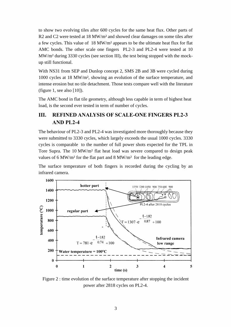
The surface temperature of both fingers is recorded during the cycling by an
infrared camera.
Figure 2 : time evolution of the surface temperature after stopping the incident
power after 2818 cycles on PL2-4.

4
The infrared view shows regular and hotter parts (figure 2). The hotter parts can be
attributed to numerous effects such as deteriorated bonds, lower tile conductivity,
local differences in the surface emissivity and non evenness of the beam. After the
cycling, surface temperature of both parts versus time are extracted by averaging
on 10*10 pixels zones (figure 2).
The surface temperature is calculated on the plateau and the time constant during
the cooling of the structure. The emissivity of the surface was set to 0.85.
Calibration shots before and after the tests showed that the correction coefficient
(transmission of the windows, tile emissivity, etc...) didn't noticeably changed
during tests. Only the cycles with a heat flux higher than 10 MW/m² (ranging from
10.6 to 11.5 MW/m²) were taken into account in this study. The surface
temperatures were normalised to 10 MW/m² according to finite element
calculations to allow comparison. The normalised surface temperature of regular
and hotter parts of PL2-3 and PL2-4 are given versus the number of cycles
(figure 3).
Figure 3 : Evolution of the surface temperature versus number of cycles for TPL
prototype elements.
The temperatures of the regular tiles of both fingers are almost constant, around
800°C. Hotter parts on both fingers show a steady increase of the temperature with
the cycling, from 950°C to 1350°C. The temperature rise of the hot tiles cannot be
attributed to lower tile conductivity or beam profile, which are constant during the
test. For this reason, this temperature rise is linked to progressive damage at the
interface, either as the progression of a crack or to progressive micro-cracking.

5
The temperature variation on neighbouring points gives the uncertainty of the
method. For 0, 500, 1000 and 3000 cycles where at least two temperatures for close
number of cycles are known, the fluctuations can be evaluated to 30 °C. Therefore,
the temperature rise of ~ 400°C of the hotter parts of PL2-3 and PL2-4 is significant.
The interface damage is also characterized by a longer time response of the tiles.
The time constants of the tiles are calculated during the transients. They are given
figure 4 for hotter and regular parts.
Figure 4 : Evolution of the time constants.
Rather big fluctuations are observed, around 0.07 second while the time constant is
around 0.7 second. However, different evolutions between the spots are still
significant. The time constants of the regular zones are approximately constant,
while those of the hotter parts always increase with the number of cycles. The hotter
tiles always finish with longer time constants than the regular tiles. For PL2-3, the
increase is around 23 % of the initial value, and for PL2-4 around 12%. The time
constants, although less precise than the surface temperature measurements,
confirm the degradation of the heat transfer capability of the structure. However,

6
the damaged tiles remain remarkably actively cooled, with time constants smaller
than 1 second and a surface temperature still acceptable for operation.
IV. MACROGRAPHIC OBSERVATIONS
Macro-examinations were done in an attempt to link the surface temperature rise to
defects. However, this task is made more difficult because macroscopic defects
such as large cracks appear only on tiles that underwent a heat flux higher
than ~15 MW/m². Elements fatigued at 10 MW/m² (like PL2-3 and PL2-4) don't
show much more defects as uncycled ones.
Examinations show that defects can appear in three areas, namely the composite,
the bond and the soft copper layer, the latest being not addressed here
Figure 5 : Macrography of the heat sink after tests at 18 MW/m² (the defective tile
was removed in laboratory)
On broken tiles removed from the mock-up after test at 18 MW/m² (figure 5), the
copper is mainly black, with many cones visible. The cones are made out of copper
that has solidified in the laser - machined holes in the CFCduring the AMC process.
Fibre bundles often remain attached to the copper. Very few copper is visible on
the fractured area of the tile. These elements indicate that such cracks propagate
mainly in the CFC or just beneath. Moreover, some black dust falls from the tile,
suggesting a disintegration of the CFC material in the vicinity of the bond.
In the CFC (figure 6), cracks are observed above the cones, on top of the cones or
between cones. On the edges, cracks start in the CFC in front of the cones. Inside
the tiles, the cracks begin at the interface to copper or inside the CFC. Cracks can
be observed at the interface between the copper and the CFC. More often such
cracks are hybrid, that is they propagate indifferently in the CFC or at the interface
of the CFC to copper. In these areas, the cones recede from the CFC, leaving a crack

7
that follows the cones or sometimes goes through the CFC between two cones. On
some very damaged tiles, continuous cracks that go straight through the cone and
the CFC could be observed.
Figure 6 : Macrography of cracks in the CFC and at the interface CFC-copper.
Internal voids in the CFC near the interface are sometime filled with copper or
carbides. Such inclusions in the CFC are to expand and shrink during thermal
cycling. As the CFC has a lower thermal expansion coefficient, it will undergo
cyclic compression. This suggests a damage mechanism which could explain the
disintegration of the CFC above the bond. In some cases, such inclusions were
observed above cracks, showing that the crack was subsequent to the manufacture
of the AMC bond.
The variety of defects suggest that many damage mechanisms can take place. No
evidence of any weak link can be found ; damages are distributed throughout the
bond. No simple description of the bond fatigue can be given and further
investigations are necessary. This is currently being done with specific experiments,
like tensile tests, shear tests and dilatometric measurements.
V. DISCUSSION
Finite element calculations are done to evaluate the stresses in the structure of a
finger. A new non-linear model was specially developed and implemented for the
CFC [11]. Stresses in a CFC tile of the LPT for 10 MW/m² and a computation of
the Tsai-Wu criterion are shown figure 7.

8
In most of the tile, the criterion exceeds 1, showing the CFC material should break.
Even if the criterion may be overestimated, the level of stress explains the observed
cracks. It explains also the kind of disintegration of the CFC observed above the
bond. However, the cracks also allow the CFC to accommodate somehow the
imposed deformation, which could explain that damaged tiles still hold to the heat
sink. These results also point out the limitation of the Tsai-Wu criterion, which isn't
suitable for this configuration. A new criterion is currently under development at
Tore Supra to characterize the stress level.
Figure 7 : Stresses (MPa) in a CFC tile under 10 MW/m² (2D generalised plain
strain calculation)
The very thin CFC-copper interface is more difficult to analyse and modelize. It
was shown in section IV that cracking also occurs there. Seemingly, a key
advantage of the AMC technology comes from the important increase of the
interface surface created by the cones. Assuming 0.25 mm high cones with a
periodicity of 0.25 mm, and a base radius of 0.08 mm, the increase of the area of
the interface amounts to 175 % compared to a flat one. Even with an interface
weaker than the base materials, the surface increase can compensate its reduction
of strength.
VI. CONCLUSION
AMC flat bonds have proved their ability to sustain high heat fluxes and thermal
fatigue. Much higher fluxes than the design value of Tore Supra combined with
cycling are necessary to observe damages. This result allows to enter the
manufacturing stage, and approximately 1000 fingers totalling roughly 8 m² of bond
have been ordered for the toroïdal pumped limiter and the RF antennas lateral
protections for Tore Supra. Developments are still under way to prepare future
plasma facing components which will have to sustain higher heat fluxes than those

9
of today. The macrobloc geometry could allow higher heat fluxes. Changes in the
local geometry near the singular point of flat tiles are also investigated to delay the
progression of damage.
REFERENCES
[1] Development of high thermal flux components for continuous operation in
tokamaks, J. Schlosser, A. Cardella, P. Chappuis et al., Proc. of the 14th
IEEE/NPSS symposium, San Diego, 1991, pp. 350-356.
[2] Brazing of the Tore Supra actively cooled phase III limiter, R.E. Nygren,
C.A. Walker, T.J. Lutz et al., JNM 212-215(1994)1621-1626.
[3] Mechanics of brazed joint and compliant layers in high heat flux
components, G. Lovato, F. Moret, G. Chaumat et al., Proc. 18th Symp. on
Fusion Technology, Karlsruhe, 1994, pp. 247-250.
[4] The manufacturing and testing of toroïdal pumped limiter prototype
elements for Tore Supra, T. Huber, L. Plöchl, N Reheis et al., Proc. of the
16th IEEE/NPSS Symp. on Fusion Engineering, 1995, Champaign Illinois,
USA, pp. 716-719.
[5] Development and testing of CFC-copper high heat flux element, R. Mitteau,
P. Chappuis, P. Deschamps et al., Proc. 18th Symp. on Fusion Technology,
Karlsruhe, 1994, pp. 435-438.
[6] Development for an actively cooled Toroïdal Pumped Limiter for Tore
Supra, J. Schlosser, P. Chappuis, L. Doceul et al., Proc. 19th Symp. on
Fusion Technology, Lisbon, 1996, pp. 447-450.
[7] Tore Supra ICRH antennas for long pulse operation, G. Agarici et al.,
accepted at 17th IEEE/NPSS Symp.,San Diego, october 1997, to be
published.
[8] Upgrading of EB200 high thermal flux station for fusion experiments needs,
M. Diotalevy, M. Febvre, Proc. 19th Symp. on Fusion Technology, Lisbon,
1996, pp. 491-494.
[9] Manufacture and testing of small-scale mock-ups for the ITER divertor,
G. Vieider, P. Chappuis, L. Plöchl et al., Proc. 19th Symp. on Fusion
Technology, Lisbon, 1996, pp. 275-278.
[10] R. Tivey and M. Ulrichson, ITER EDA Newsletter, Vol2 N2, February
1997.
[11] Fatigue of a carbon fibre material under thermomechanical cycling,
L. Moncel, P. Chappuis, J. Schlosser et al., Proc. of 1st Int. Conf. on Fatigue
of Composites, Paris, 1997, pp. 213-220.