EVERSOURCE MODEL AND TECHNICAL DATA REQUEST LIST FOR ...
13
EVERSOURCE MODEL AND TECHNICAL DATA REQUEST LIST FOR AFFECTED SYSTEM OPERATOR (ASO) TRANSMISSION STUDIES In preparation for conducting the ASO studies, Eversource would like to provide customers with the list of technical information that will be needed in advance so that customers can begin pulling this information together. All data below will need to be received for each project before the ASO study can commence. It is assumed that all the DER included in the ASO transmission studies are non-FERC. The modeling and data requests are for studies to support the ISO-NE Level 0 and Level 3 Proposed Plan Application (PPA). EVERSOURCE DATA AND MODEL REQUEST TO SUPPORT ISO-NE LEVEL 0 PPA APPROVAL All applications that are greater than 1MW must provide a fully working PSCAD model and the following inverter modeling information. • Description of the Battery Energy Storage System (BESS) if the project includes any BESS. o If the project includes both BESS and PV how are the BESS and PV connected (AC coupled, or DC coupled)? o Can the BESS charge from the grid? • Inverter manufacturer, inverter model name, version and kW rating. • Fully functional PSCAD models of the projects are required. PSCAD model requirements are included in the attached Appendix B. • The inverter’s frequency and voltage relay trip settings must meet the requirements found in the attached ISO-NE Inverter Source Requirement Document in Appendix C. 1. PROJECT PHYSICAL INFORMATION • Stamped project one-line diagram (must include inverters) 2. PROJECT MARKET INFORMATION • Project projected in-service date • Project will indicate if it will be a Settlement Only Generator (SOG) or if it intends on participating in the ISO-NE market as a Generator in accordance to ISO-NE designation in OP- 14 1 . EVERSOURCE DATA AND MODEL REQUEST FOR STUDY TO SUPPORT ISO-NE LEVEL 3 PPA APPROVAL 1. PROJECT PHYSICAL INFORMATION • Stamped project one-line diagram (must include inverters) 2. PROJECT MARKET INFORMATION 1 ISO New England Operating Procedure No. 14 - Technical Requirements for Generators, Demand Response Resources, Asset Related Demands and Alternative Technology Regulation Resources
Transcript of EVERSOURCE MODEL AND TECHNICAL DATA REQUEST LIST FOR ...
EVERSOURCE MODEL AND TECHNICAL DATA REQUEST LIST FOR AFFECTED SYSTEM OPERATOR (ASO) TRANSMISSION STUDIES
In preparation for conducting the ASO studies, Eversource would like to provide customers with the list of technical information that will be needed in advance so that customers can begin pulling this information together. All data below will need to be received for each project before the ASO study can commence. It is assumed that all the DER included in the ASO transmission studies are non-FERC. The modeling and data requests are for studies to support the ISO-NE Level 0 and Level 3 Proposed Plan Application (PPA).
EVERSOURCE DATA AND MODEL REQUEST TO SUPPORT ISO-NE LEVEL 0 PPA APPROVAL All applications that are greater than 1MW must provide a fully working PSCAD model and the following inverter modeling information.
• Description of the Battery Energy Storage System (BESS) if the project includes any BESS. o If the project includes both BESS and PV how are the BESS and PV connected (AC
coupled, or DC coupled)? o Can the BESS charge from the grid?
• Inverter manufacturer, inverter model name, version and kW rating. • Fully functional PSCAD models of the projects are required. PSCAD model requirements are
included in the attached Appendix B. • The inverter’s frequency and voltage relay trip settings must meet the requirements found
in the attached ISO-NE Inverter Source Requirement Document in Appendix C.
1. PROJECT PHYSICAL INFORMATION • Stamped project one-line diagram (must include inverters)
2. PROJECT MARKET INFORMATION
• Project projected in-service date • Project will indicate if it will be a Settlement Only Generator (SOG) or if it intends on
participating in the ISO-NE market as a Generator in accordance to ISO-NE designation in OP-141.
EVERSOURCE DATA AND MODEL REQUEST FOR STUDY TO SUPPORT ISO-NE LEVEL 3 PPA APPROVAL
1. PROJECT PHYSICAL INFORMATION
• Stamped project one-line diagram (must include inverters)
2. PROJECT MARKET INFORMATION
1 ISO New England Operating Procedure No. 14 - Technical Requirements for Generators, Demand Response Resources, Asset Related Demands and Alternative Technology Regulation Resources

• Project projected in-service date • Project will indicate if it will be a Settlement Only Generator (SOG) or if it intends on
participating in the ISO-NE market as a Generator in accordance to ISO-NE designation in OP-14
3. PROJECT TECHNICAL INFORMATION • Conductor type and distances in mile between inverters/GSUs • Conductor type and length of dedicated feeder to POI in miles • Generator step-up (GSU) transformer size (MVA), impedance (%Z), and X/R ratio • GSU transformer number of taps and per unit size of each (typical is +/-2 steps, each at 2.5%
or, 0.95, 0.975, 1.0,1.025, 1.05 per unit) • Project inverter modeling information (>1MW and <5MW only)
o Eversource to use the DER_A inverter stability model • Project inverter modeling information (≥5MW only)
o Datasheet and manual o Reactive capability curve and/or data tables necessary to create the capability curve
when the project output is a maximum (Pmax) o Stability model in PSS/E standard library model format. Note ISO-NE does not
accept user- written models. Stability models must consist of the types listed in the latest version of the
NERC List of Acceptable Models for Interconnection-Wide Modeling, as required by the ISO New England Compliance Bulletin MOD-032 dated April, 20202. The NERC list of Acceptable Renewable Energy Resource Models as of June 8, 2021 is listed in Appendix A.
The stability model must include accurate voltage and frequency control parameters if the voltage and frequency control functions of the model are disabled.
• Comprehensive project inverter modeling information o Description of the Battery Energy Storage System (BESS) if the project includes any
BESS. If the project includes both BESS and PV how are the BESS and PV
connected (AC coupled, or DC coupled)? Can the BESS charge from the grid?
o Inverter manufacturer, inverter model name, version and kW rating. o Fully functional PSCAD models of the projects are required. PSCAD model
requirements are included in the attached Appendix B. o The inverter’s frequency and voltage relay trip settings must meet the requirements
found in the attached ISO-NE Inverter Source Requirement Document in Appendix C.
2 https://iso-ne.com/static-assets/documents/2015/06/iso_new_england_compliance_bulletin_mod_032.pdf
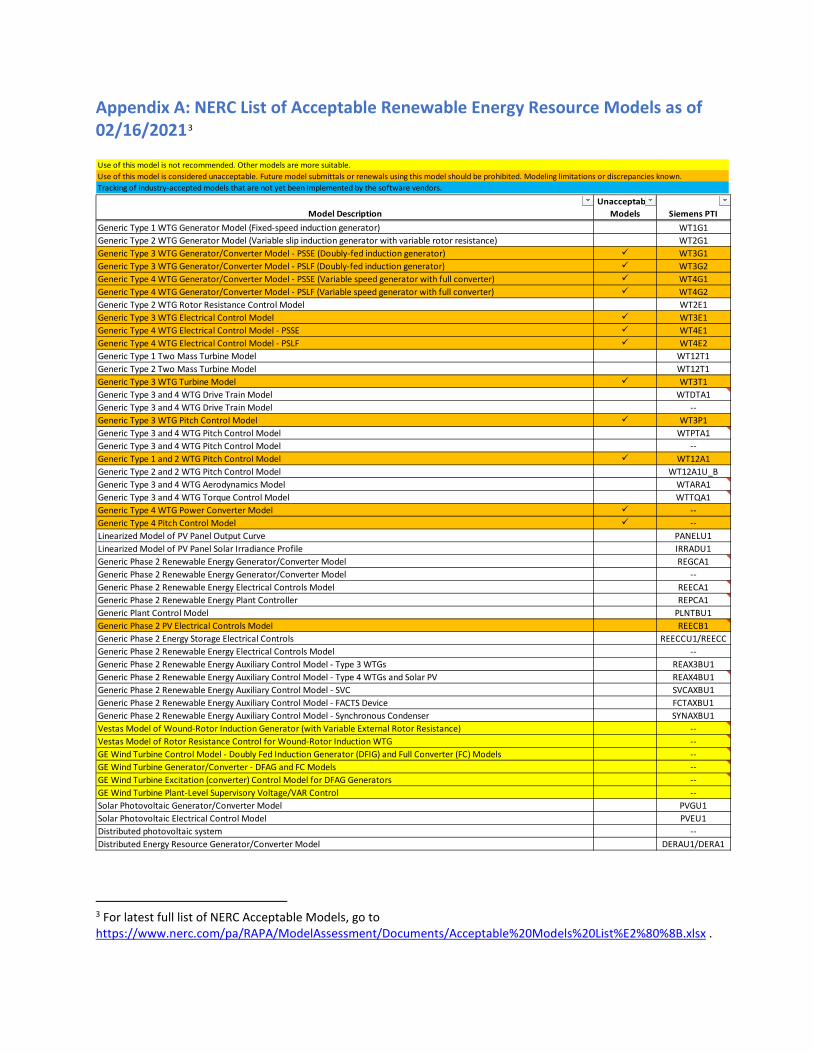
Appendix A: NERC List of Acceptable Renewable Energy Resource Models as of 02/16/20213
3 For latest full list of NERC Acceptable Models, go to https://www.nerc.com/pa/RAPA/ModelAssessment/Documents/Acceptable%20Models%20List%E2%80%8B.xlsx .
Use of this model is not recommended. Other models are more suitable.Use of this model is considered unacceptable. Future model submittals or renewals using this model should be prohibited. Modeling limitations or discrepancies known.Tracking of industry-accepted models that are not yet been implemented by the software vendors.
Model Description Siemens PTI Unacceptable
ModelsGeneric Type 1 WTG Generator Model (Fixed-speed induction generator) WT1G1Generic Type 2 WTG Generator Model (Variable slip induction generator with variable rotor resistance) WT2G1Generic Type 3 WTG Generator/Converter Model - PSSE (Doubly-fed induction generator) WT3G1Generic Type 3 WTG Generator/Converter Model - PSLF (Doubly-fed induction generator) WT3G2Generic Type 4 WTG Generator/Converter Model - PSSE (Variable speed generator with full converter) WT4G1Generic Type 4 WTG Generator/Converter Model - PSLF (Variable speed generator with full converter) WT4G2Generic Type 2 WTG Rotor Resistance Control Model WT2E1Generic Type 3 WTG Electrical Control Model WT3E1Generic Type 4 WTG Electrical Control Model - PSSE WT4E1Generic Type 4 WTG Electrical Control Model - PSLF WT4E2Generic Type 1 Two Mass Turbine Model WT12T1Generic Type 2 Two Mass Turbine Model WT12T1Generic Type 3 WTG Turbine Model WT3T1Generic Type 3 and 4 WTG Drive Train Model WTDTA1Generic Type 3 and 4 WTG Drive Train Model --Generic Type 3 WTG Pitch Control Model WT3P1Generic Type 3 and 4 WTG Pitch Control Model WTPTA1Generic Type 3 and 4 WTG Pitch Control Model --Generic Type 1 and 2 WTG Pitch Control Model WT12A1Generic Type 2 and 2 WTG Pitch Control Model WT12A1U_BGeneric Type 3 and 4 WTG Aerodynamics Model WTARA1Generic Type 3 and 4 WTG Torque Control Model WTTQA1Generic Type 4 WTG Power Converter Model --Generic Type 4 Pitch Control Model --Linearized Model of PV Panel Output Curve PANELU1Linearized Model of PV Panel Solar Irradiance Profile IRRADU1Generic Phase 2 Renewable Energy Generator/Converter Model REGCA1Generic Phase 2 Renewable Energy Generator/Converter Model --Generic Phase 2 Renewable Energy Electrical Controls Model REECA1Generic Phase 2 Renewable Energy Plant Controller REPCA1Generic Plant Control Model PLNTBU1Generic Phase 2 PV Electrical Controls Model REECB1Generic Phase 2 Energy Storage Electrical Controls REECCU1/REECCGeneric Phase 2 Renewable Energy Electrical Controls Model --Generic Phase 2 Renewable Energy Auxiliary Control Model - Type 3 WTGs REAX3BU1Generic Phase 2 Renewable Energy Auxiliary Control Model - Type 4 WTGs and Solar PV REAX4BU1Generic Phase 2 Renewable Energy Auxiliary Control Model - SVC SVCAXBU1Generic Phase 2 Renewable Energy Auxiliary Control Model - FACTS Device FCTAXBU1Generic Phase 2 Renewable Energy Auxiliary Control Model - Synchronous Condenser SYNAXBU1Vestas Model of Wound-Rotor Induction Generator (with Variable External Rotor Resistance) --Vestas Model of Rotor Resistance Control for Wound-Rotor Induction WTG --GE Wind Turbine Control Model - Doubly Fed Induction Generator (DFIG) and Full Converter (FC) Models --GE Wind Turbine Generator/Converter - DFAG and FC Models --GE Wind Turbine Excitation (converter) Control Model for DFAG Generators --GE Wind Turbine Plant-Level Supervisory Voltage/VAR Control --Solar Photovoltaic Generator/Converter Model PVGU1Solar Photovoltaic Electrical Control Model PVEU1Distributed photovoltaic system --Distributed Energy Resource Generator/Converter Model DERAU1/DERA1
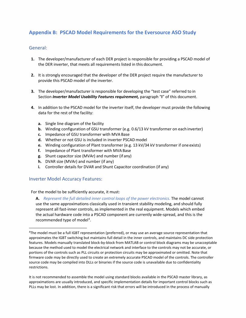
Appendix B: PSCAD Model Requirements for the Eversource ASO Study
General:
1. The developer/manufacturer of each DER project is responsible for providing a PSCAD model of the DER inverter, that meets all requirements listed in this document.
2. It is strongly encouraged that the developer of the DER project require the manufacturer to
provide this PSCAD model of the inverter.
3. The developer/manufacturer is responsible for developing the “test case” referred to in Section Inverter Model Usability Features requirement, paragraph “I” of this document.
4. In addition to the PSCAD model for the inverter itself, the developer must provide the following
data for the rest of the facility:
a. Single line diagram of the facility b. Winding configuration of GSU transformer (e.g. 0.6/13 kV transformer on each inverter) c. Impedance of GSU transformer with MVA Base d. Whether or not GSU is included in inverter PSCAD model e. Winding configuration of Plant transformer (e.g. 13 kV/34 kV transformer if one exists) f. Impedance of Plant transformer with MVA Base g. Shunt capacitor size (MVAr) and number (if any) h. DVAR size (MVAr) and number (if any) i. Controller details for DVAR and Shunt Capacitor coordination (if any)
Inverter Model Accuracy Features:
For the model to be sufficiently accurate, it must: A. Represent the full detailed inner control loops of the power electronics. The model cannot use the same approximations classically used in transient stability modeling, and should fully represent all fast-inner controls, as implemented in the real equipment. Models which embed the actual hardware code into a PSCAD component are currently wide-spread, and this is the recommended type of model4.
4The model must be a full IGBT representation (preferred), or may use an average source representation that approximates the IGBT switching but maintains full detail in the inner controls, and maintains DC side protection features. Models manually translated block-by-block from MATLAB or control block diagrams may be unacceptable because the method used to model the electrical network and interface to the controls may not be accurate, or portions of the controls such as PLL circuits or protection circuits may be approximated or omitted. Note that firmware code may be directly used to create an extremely accurate PSCAD model of the controls. The controller source code may be compiled into DLLs or binaries if the source code is unavailable due to confidentiality restrictions. It is not recommended to assemble the model using standard blocks available in the PSCAD master library, as approximations are usually introduced, and specific implementation details for important control blocks such as PLLs may be lost. In addition, there is a significant risk that errors will be introduced in the process of manually
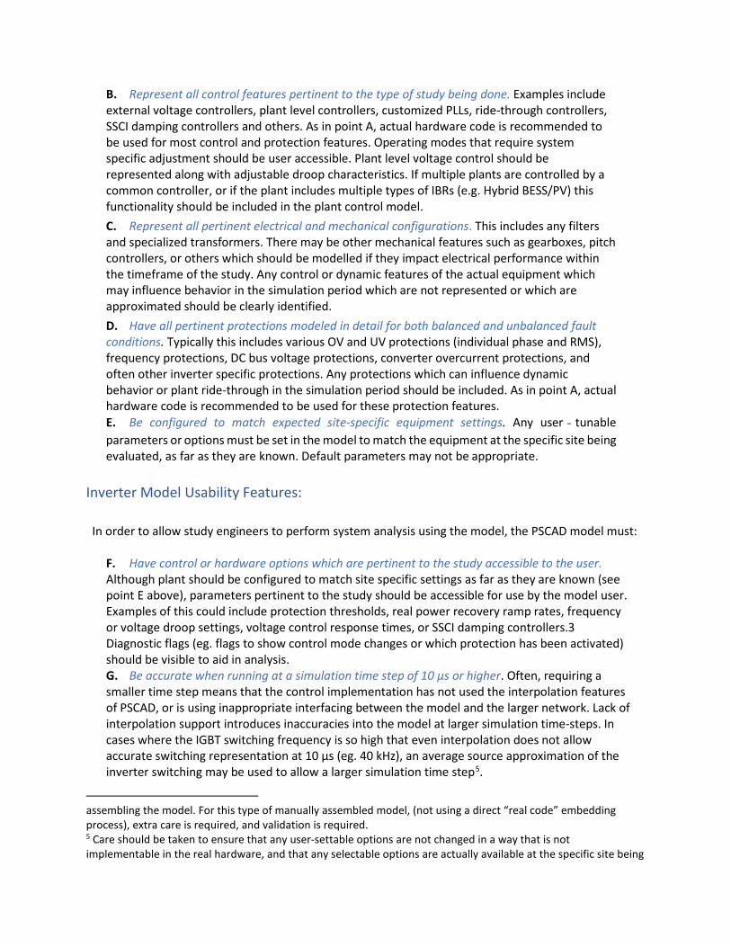
B. Represent all control features pertinent to the type of study being done. Examples include external voltage controllers, plant level controllers, customized PLLs, ride-through controllers, SSCI damping controllers and others. As in point A, actual hardware code is recommended to be used for most control and protection features. Operating modes that require system specific adjustment should be user accessible. Plant level voltage control should be represented along with adjustable droop characteristics. If multiple plants are controlled by a common controller, or if the plant includes multiple types of IBRs (e.g. Hybrid BESS/PV) this functionality should be included in the plant control model. C. Represent all pertinent electrical and mechanical configurations. This includes any filters and specialized transformers. There may be other mechanical features such as gearboxes, pitch controllers, or others which should be modelled if they impact electrical performance within the timeframe of the study. Any control or dynamic features of the actual equipment which may influence behavior in the simulation period which are not represented or which are approximated should be clearly identified. D. Have all pertinent protections modeled in detail for both balanced and unbalanced fault conditions. Typically this includes various OV and UV protections (individual phase and RMS), frequency protections, DC bus voltage protections, converter overcurrent protections, and often other inverter specific protections. Any protections which can influence dynamic behavior or plant ride-through in the simulation period should be included. As in point A, actual hardware code is recommended to be used for these protection features. E. Be configured to match expected site-specific equipment settings. Any user ‐ tunable parameters or options must be set in the model to match the equipment at the specific site being evaluated, as far as they are known. Default parameters may not be appropriate.
Inverter Model Usability Features:
In order to allow study engineers to perform system analysis using the model, the PSCAD model must:
F. Have control or hardware options which are pertinent to the study accessible to the user. Although plant should be configured to match site specific settings as far as they are known (see point E above), parameters pertinent to the study should be accessible for use by the model user. Examples of this could include protection thresholds, real power recovery ramp rates, frequency or voltage droop settings, voltage control response times, or SSCI damping controllers.3 Diagnostic flags (eg. flags to show control mode changes or which protection has been activated) should be visible to aid in analysis. G. Be accurate when running at a simulation time step of 10 µs or higher. Often, requiring a smaller time step means that the control implementation has not used the interpolation features of PSCAD, or is using inappropriate interfacing between the model and the larger network. Lack of interpolation support introduces inaccuracies into the model at larger simulation time-steps. In cases where the IGBT switching frequency is so high that even interpolation does not allow accurate switching representation at 10 μs (eg. 40 kHz), an average source approximation of the inverter switching may be used to allow a larger simulation time step5.
assembling the model. For this type of manually assembled model, (not using a direct “real code” embedding process), extra care is required, and validation is required. 5 Care should be taken to ensure that any user-settable options are not changed in a way that is not implementable in the real hardware, and that any selectable options are actually available at the specific site being

H. Operate at a range of simulation time steps. The model should not be restricted to operating at a single time step, but should be able to operate within a range (eg. 10 μs – 20 μs). I. Have the ability to disable protection models. Many studies result in inadvertent tripping of converter equipment, and the ability to disable protection functions temporarily provides study engineers with valuable system diagnostic information. J. Include documentation and a sample implementation test case. Test case models should be configured according to the site-specific real equipment configuration up to the Point of Interconnection. This would include (for example): aggregated generator model, aggregated generator transformer, equivalent collector branch, main step up transformers, gen tie line, and any other static or dynamic reactive resources. Test case should use a single machine infinite bus representation of the system, configured with an appropriate representative SCR6. Access to technical support engineers is desirable. K. Have an identification mechanism for configuration. The model documentation should provide a clear way to identify the specific settings and equipment configuration which will be used in any study, such that during commissioning the settings used in the studies can be checked. This may be control revision codes, settings files, or a combination of these and other identification measures. L. Accept external reference variables. This includes real and reactive power ordered values for Q control modes, or voltage reference values for voltage control modes. Model must accept these reference variables for initialization and be capable of changing these reference variables mid- simulation, i.e. dynamic signal references. M. Be capable of initializing itself. Once provided with initial condition variables, the model must initialize and ramp to the ordered output without external input from simulation engineers. Any slower control functions which are included (such as switched shunt controllers or power plant controllers) should also accept initial condition variables if required. Note that during the first few seconds of simulation (eg. 0-2 seconds), the system voltage and corresponding terminal conditions may deviate from nominal values due to other system devices initializing, and the model should be able to tolerate these deviations or provide a variable initialization time. N. Have the ability to scale plant capacity. The active power capacity of the model must be scalable in some way, either internally or through an external scaling transformer7. This is distinct from a dispatchable power order and is used for modeling different capacities of plant or breaking a lumped equivalent plant into smaller composite models. O. Have the ability to dispatch its output to values less than nameplate. This is distinct from scaling a plant from one unit to more than one, and is used for testing plant behavior at various operating points. P. Initialize quickly. Model must reach its ordered initial conditions as quickly as possible (for example <5 seconds) to user supplied terminal conditions.
Study Efficiency Features:
In addition, the following elements are required to improve study efficiency, model compatibility, and
considered. Discussion is recommended with the manufacturer prior to any changes being made in model configuration. 6 Representative SCR should reflect approximate N-1 interconnection SCR where possible, especially if the system is expected to be weak. If the system strength is not known, using a relatively low SCR in the test system, such as 2.5, may help to avoid issues during study phases. 7 A free publicly available scaling transformer suitable for this purpose is available in the E-Tran library.
enable other studies which include the model to be run as efficiently as possible. If these features are not supported, additional discussion is required:
Q. Model must be compiled with Intel Fortran version 12 or higher. Model must not be dependent on a specific Fortran version to run. R. Model should be compatible with PSCAD version 4.6.3 and higher. S. Model supports multiple instances of its own definition in the same simulation case. T. Model supports the PSCAD “timed snapshot” feature accessible through project settings. U. Model supports the PSCAD “multiple run” feature. V. Model does not use or rely upon global variables in the PSCAD environment. W. Model should not utilize multiple layers in the PSCAD environment, including ‘disabled’ layers.

Appendix C: Inverter Source Requirement Document of ISO New England
February 6, 2018 Page 1
ISO-NE PUBLIC
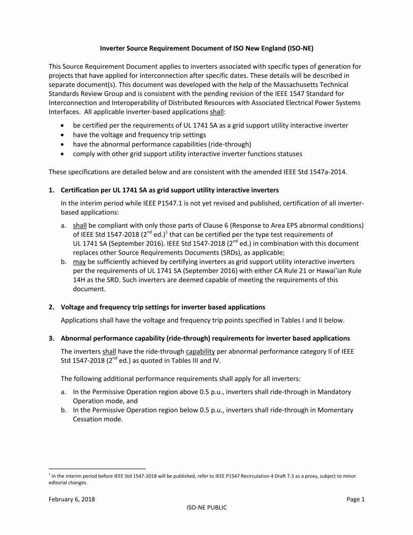
Inverter Source Requirement Document of ISO New England (ISO-NE) This Source Requirement Document applies to inverters associated with specific types of generation for projects that have applied for interconnection after specific dates. These details will be described in separate document(s). This document was developed with the help of the Massachusetts Technical Standards Review Group and is consistent with the pending revision of the IEEE 1547 Standard for Interconnection and Interoperability of Distributed Resources with Associated Electrical Power Systems Interfaces. All applicable inverter-based applications shall:
be certified per the requirements of UL 1741 SA as a grid support utility interactive inverter
have the voltage and frequency trip settings
have the abnormal performance capabilities (ride-through)
comply with other grid support utility interactive inverter functions statuses These specifications are detailed below and are consistent with the amended IEEE Std 1547a-2014. 1. Certification per UL 1741 SA as grid support utility interactive inverters
In the interim period while IEEE P1547.1 is not yet revised and published, certification of all inverter-based applications:
a. shall be compliant with only those parts of Clause 6 (Response to Area EPS abnormal conditions) of IEEE Std 1547-2018 (2nd ed.)1 that can be certified per the type test requirements of UL 1741 SA (September 2016). IEEE Std 1547-2018 (2nd ed.) in combination with this document replaces other Source Requirements Documents (SRDs), as applicable;
b. may be sufficiently achieved by certifying inverters as grid support utility interactive inverters per the requirements of UL 1741 SA (September 2016) with either CA Rule 21 or Hawai’ian Rule 14H as the SRD. Such inverters are deemed capable of meeting the requirements of this document.
2. Voltage and frequency trip settings for inverter based applications
Applications shall have the voltage and frequency trip points specified in Tables I and II below. 3. Abnormal performance capability (ride-through) requirements for inverter based applications
The inverters shall have the ride-through capability per abnormal performance category II of IEEE Std 1547-2018 (2nd ed.) as quoted in Tables III and IV. The following additional performance requirements shall apply for all inverters:
a. In the Permissive Operation region above 0.5 p.u., inverters shall ride-through in Mandatory Operation mode, and
b. In the Permissive Operation region below 0.5 p.u., inverters shall ride-through in Momentary Cessation mode.
1 In the interim period before IEEE Std 1547-2018 will be published, refer to IEEE P1547 Recirculation 4 Draft 7.3 as a proxy, subject to minor editorial changes.
February 6, 2018 Page 2
ISO-NE PUBLIC
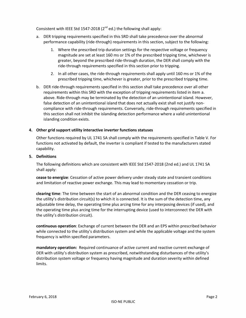
Consistent with IEEE Std 1547-2018 (2nd ed.) the following shall apply:
a. DER tripping requirements specified in this SRD shall take precedence over the abnormal performance capability (ride-through) requirements in this section, subject to the following:
1. Where the prescribed trip duration settings for the respective voltage or frequency magnitude are set at least 160 ms or 1% of the prescribed tripping time, whichever is greater, beyond the prescribed ride-through duration, the DER shall comply with the ride-through requirements specified in this section prior to tripping.
2. In all other cases, the ride-through requirements shall apply until 160 ms or 1% of the prescribed tripping time, whichever is greater, prior to the prescribed tripping time.
b. DER ride-through requirements specified in this section shall take precedence over all other requirements within this SRD with the exception of tripping requirements listed in item a. above. Ride-through may be terminated by the detection of an unintentional island. However, false detection of an unintentional island that does not actually exist shall not justify non-compliance with ride-through requirements. Conversely, ride-through requirements specified in this section shall not inhibit the islanding detection performance where a valid unintentional islanding condition exists.
4. Other grid support utility interactive inverter functions statuses
Other functions required by UL 1741 SA shall comply with the requirements specified in Table V. For functions not activated by default, the inverter is compliant if tested to the manufacturers stated capability.
5. Definitions
The following definitions which are consistent with IEEE Std 1547-2018 (2nd ed.) and UL 1741 SA shall apply:
cease to energize: Cessation of active power delivery under steady state and transient conditions and limitation of reactive power exchange. This may lead to momentary cessation or trip. clearing time: The time between the start of an abnormal condition and the DER ceasing to energize the utility’s distribution circuit(s) to which it is connected. It is the sum of the detection time, any adjustable time delay, the operating time plus arcing time for any interposing devices (if used), and the operating time plus arcing time for the interrupting device (used to interconnect the DER with the utility’s distribution circuit).
continuous operation: Exchange of current between the DER and an EPS within prescribed behavior while connected to the utility’s distribution system and while the applicable voltage and the system frequency is within specified parameters.
mandatory operation: Required continuance of active current and reactive current exchange of DER with utility’s distribution system as prescribed, notwithstanding disturbances of the utility’s distribution system voltage or frequency having magnitude and duration severity within defined limits.

February 6, 2018 Page 3
ISO-NE PUBLIC
momentary cessation: Temporarily cease to energize the utility’s distribution system while connected to the utility’s distribution system, in response to a disturbance of the applicable voltages or the system frequency, with the capability of immediate restore output of operation when the applicable voltages and the system frequency return to within defined ranges.
permissive operation: operating mode where the DER performs ride-through either in mandatory operation or in momentary cessation, in response to a disturbance of the applicable voltages or the system frequency.
February 6, 2018 Page 4
ISO-NE PUBLIC
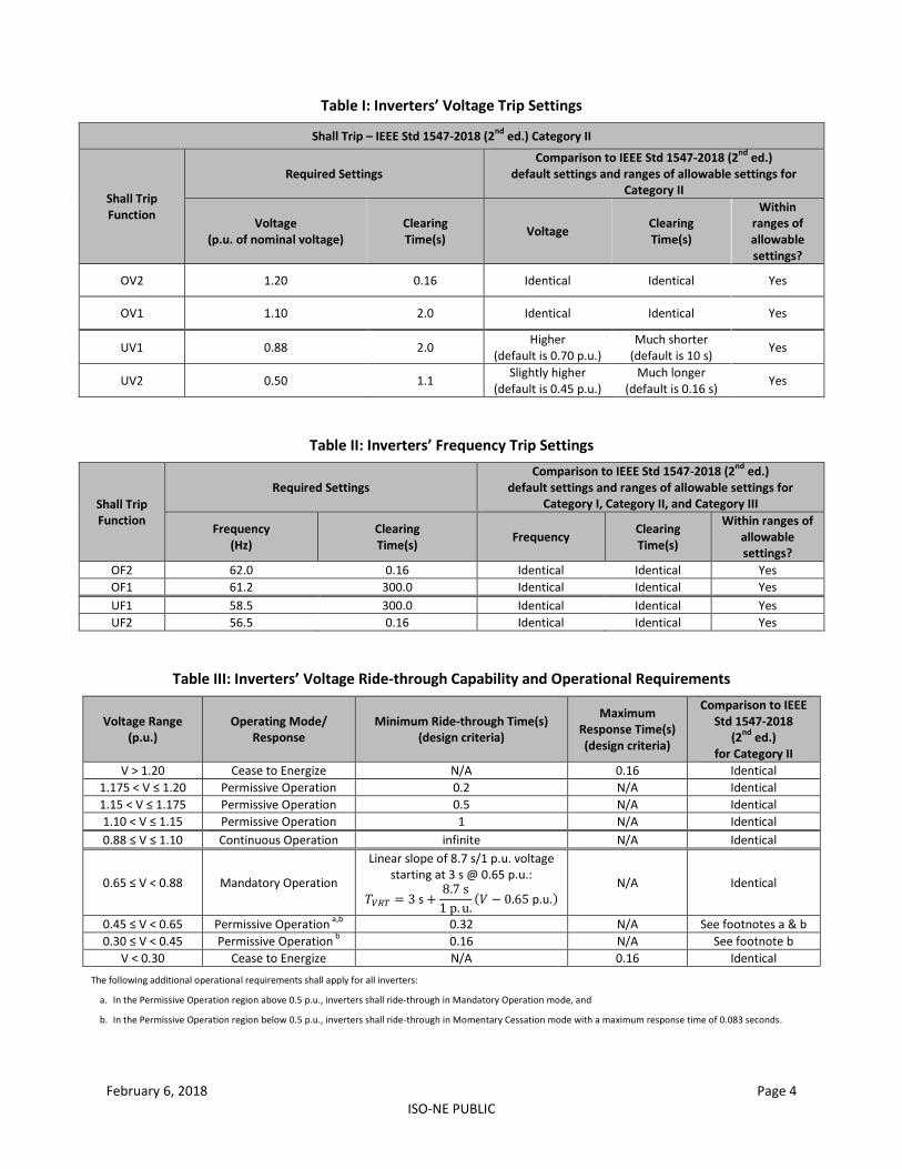
Table I: Inverters’ Voltage Trip Settings
Shall Trip – IEEE Std 1547-2018 (2nd
ed.) Category II
Shall Trip Function
Required Settings Comparison to IEEE Std 1547-2018 (2
nd ed.)
default settings and ranges of allowable settings for Category II
Voltage (p.u. of nominal voltage)
Clearing Time(s)
Voltage Clearing Time(s)
Within ranges of allowable settings?
OV2 1.20 0.16 Identical Identical Yes
OV1 1.10 2.0 Identical Identical Yes
UV1 0.88 2.0 Higher
(default is 0.70 p.u.) Much shorter
(default is 10 s) Yes
UV2 0.50 1.1 Slightly higher
(default is 0.45 p.u.) Much longer
(default is 0.16 s) Yes
Table II: Inverters’ Frequency Trip Settings
Shall Trip Function
Required Settings Comparison to IEEE Std 1547-2018 (2
nd ed.)
default settings and ranges of allowable settings for Category I, Category II, and Category III
Frequency (Hz)
Clearing Time(s)
Frequency Clearing Time(s)
Within ranges of allowable settings?
OF2 62.0 0.16 Identical Identical Yes
OF1 61.2 300.0 Identical Identical Yes
UF1 58.5 300.0 Identical Identical Yes
UF2 56.5 0.16 Identical Identical Yes
Table III: Inverters’ Voltage Ride-through Capability and Operational Requirements
Voltage Range (p.u.)
Operating Mode/ Response
Minimum Ride-through Time(s) (design criteria)
Maximum Response Time(s) (design criteria)
Comparison to IEEE Std 1547-2018
(2nd
ed.) for Category II
V > 1.20 Cease to Energize N/A 0.16 Identical
1.175 < V ≤ 1.20 Permissive Operation 0.2 N/A Identical
1.15 < V ≤ 1.175 Permissive Operation 0.5 N/A Identical
1.10 < V ≤ 1.15 Permissive Operation 1 N/A Identical
0.88 ≤ V ≤ 1.10 Continuous Operation infinite N/A Identical
0.65 ≤ V < 0.88 Mandatory Operation
Linear slope of 8.7 s/1 p.u. voltage starting at 3 s @ 0.65 p.u.:
𝑇𝑉𝑅𝑇 = 3 s +8.7 s
1 p. u.(𝑉 − 0.65 p.u.)
N/A Identical
0.45 ≤ V < 0.65 Permissive Operation a,b
0.32 N/A See footnotes a & b
0.30 ≤ V < 0.45 Permissive Operation b
0.16 N/A See footnote b
V < 0.30 Cease to Energize N/A 0.16 Identical
The following additional operational requirements shall apply for all inverters:
a. In the Permissive Operation region above 0.5 p.u., inverters shall ride-through in Mandatory Operation mode, and
b. In the Permissive Operation region below 0.5 p.u., inverters shall ride-through in Momentary Cessation mode with a maximum response time of 0.083 seconds.

February 6, 2018 Page 5
ISO-NE PUBLIC
Table IV: Inverters’ Frequency Ride-through Capability
Frequency Range (Hz)
Operating Mode Minimum Time(s) (design criteria)
Comparison to IEEE Std 1547-2018
(2nd
ed.) for Category II
f > 62.0 No ride-through requirements apply to this range Identical
61.2 < f ≤ 61.8 Mandatory Operation 299 Identical
58.8 ≤ f ≤ 61.2 Continuous Operation Infinite Identical
57.0 ≤ f < 58.8 Mandatory Operation 299 Identical
f < 57.0 No ride-through requirements apply to this range Identical
Table V: Grid Support Utility Interactive Inverter Functions Status
Function Default Activation State
SPF, Specified Power Factor OFF2
Q(V), Volt-Var Function with Watt or Var Priority OFF
SS, Soft-Start Ramp Rate ON
Default value: 2% of maximum current output per second
FW, Freq-Watt Function OFF
OFF
2 OFF and operating at unity PF. Or set to ON with unity PF.