EVENT UPSET)-RRTE OF MICROPROCESSOR PR..(U) · PDF filequestion of how the microprocessor test...
40
AD-R173 1?6 TECHNIQUES OF MICROPROCESSOR TESTING AND SEU (SINGLE 1/1 EVENT UPSET)-RRTE PR..(U) AEROSPACE CORP EL SEGUNO CA SPACE SCIENCES LAB R KOOA ET AL. 15 AUG 96 UNCLSSIIED R-996(649-5)-2 SDTR-9-52F/S 9/2 N
Transcript of EVENT UPSET)-RRTE OF MICROPROCESSOR PR..(U) · PDF filequestion of how the microprocessor test...

AD-R173 1?6 TECHNIQUES OF MICROPROCESSOR TESTING AND SEU (SINGLE 1/1
EVENT UPSET)-RRTE PR..(U) AEROSPACE CORP EL SEGUNO CASPACE SCIENCES LAB R KOOA ET AL. 15 AUG 96UNCLSSIIED R-996(649-5)-2 SDTR-9-52F/S 9/2 N

IIII L 2.2I . L2 0i
1.25 1q
MICROCOPY RESOLUTION TEST CHARTNATIONAL BUREAU Or STANDARDS 1963A
.%
a-. f.1
'-. w , *2~ .~ 2. * ~ J !: , x

REPORT SD-TR-86-52
to
o1 Techniques of MicroprocessorTesting and SEU-Rate Prediction
Prepared by
R. KOGA, W. A. KOLASINSKI, and M. T. MARRA 7-Space Sciences Laboratory
Laboratory OperationsThe Aerospace Corporation
El Segundo, CA 90245
ELECTE15 August 1986 1)
APPROVED FOR PUBLIC RELEASE;DISTRIBUTION UNLIMITED
Prepared for
SPACE DIVISIONAIR FORCE SYSTEMS COMMAND
Los Angeles Air Force StationP.O. Box 92960, Worldway Postal Center
Los Angeles, CA 90009-2960
LAU
L.-.
""-•C.. %

UNCLAS SIFIEDSECURITY CLASSIFICATION OF THIS PAGE (When. Dae Entewed) __________________
S..F.
REPORT DOCUMENTATION PAGE REA ISTRUCTIONS
I R POR MU mER2 GOVT ACCESSION O. 3. RECIPIENT'S CATALOG HUMME
SD-TR-86-52/9 3 744. T1T6E (and Subtitle) S. TYPE or REPORT a PERIOD COVERED
TECHINIQUES OF MICROPROCESSORTESTING AND SEU-RATE S. PERFORMING ORG. REPORT MUMMERPREDICTION TR-0086(6940-05)-20__
7. AUTMoR(s) S. CONTRACT OR GRANT NUMMUER(A)
Rokutaro Koga, Wojciech A. Kolasinski, andtichael T. Marra F04701-85.C.0086
9 PERFORMING ORGANIZATION NAMIE AND ADDRESS 10. PROGRAM ELEMENT, PROJECT. TASK 4AREA & WORK UN IT NUMBERS
The Aerospace CorporationEl Segundo, Calif. 90245 -
I I CONTROLLING OFFICE NAME ANO ADDRESS 12. REPORT CATESpace Division 15 August 1986Los Angeles Air Force Station 13. NUMMER OF PAGES
Los Angeles, Calif. 90009-2960 3514 MONITORING AGENCY NAME II AOORESS(II dillcrst from Countrolling Office) IS. SECURITY CLASS, (.1 tis roeft)
UnclassifiedtISA GECASSIFICATION/ DOWNGRAING ..
4. SCH EGUL1
S. 1S. DISTRIBUTION STATEMENT (oI tde oRepee)
Approved for public release; distribution unlimited
17. GISTRISIUTION STATEMENT (of the abstract onteoed it Stock 20. it different ft- Repoat)
10. SUPPLEMENTARY NOTES
19. KEY WORDS (Continue on rovers* ode it necessary mid Identify by block numbe")
Micropressor TestingSingle Event Upset.tadiation Hardness
.1 ~ 20. AUISTRACT (Continue an reverse aide it necessary and idenify by block num~ber)
Several different approaches have been used In the past to assess thevulnerability of microprocessors to SEU. In this report we discuss the
*advantages and disadvantages of each of these test methods, and address thequestion of how the microprocessor test results can be used to estimate .-
upset rate in space. Finally, as an application of the above techniques, wepresent the test results and predicted upset rates In synchronous orbit fora selected group of microprocessors. vc?FORM :DO 1473 UNCLASSIFIED
* . SECURITY CL.ASSIFICATION OPP THIS PAGE (When veto Entered)
~ -~4~: .:~./% ~ ~. . **** ** 5--... -t N-. -%

- .. " -x a'L
PREFACE
The authors wish to express their appreciation to The Aerospace Corpora-
tion personnel for assisting with the experiments. The authors are also
grateful to the SEU test collaborators from Harris, McDonnell Douglas, NWSC-
Crane, Analex, NASA GSFC, and Sandia, as well as the entire accelerator staff
at IUCF, HHIRF, 88-in. Cyclotron (LBL), and Bevalac (LBL), who made the SEU
testing possible.
AcceSion ForViDic TAB L
Unannounced ]IJustific~ation ............ ..........- . %.:..
B Y ............. ........ ..................... ... %D istl ib ~ ti o ni .-
... " Availability Codes ,.,
i Avail ;jdi orl O~ist S pucial ' ,
% 6.%
%
.IIa
a,.'
,.' ?*I

CONTENTS
PREFACE ...................... ......... .......... . . ......... ........ 1I • INTRODUCTION ........................ o................ ...... ...... . 9
II. MICROPROCESSOR TEST METHODS ............ o ...... ....... .......... 11
111. ILLUSTRATION OF TEST METHODS: DETAILED EXAMPLES .................. 15A. -Bit Slice Processor (2901) (Method 4) ...................... . 15
B. 16-Bit MD2815 Processor (Method 4) ............................. 20
C. 8-Bit Microcontrollers and Microprocessors
D. 16-Bit Microprocessor (Method 2) .............................. 22
E . Ot h e r De v ic e s .......... . . . . . . . . . . . . . . . . . . . . . . . . . . . .... . . . . . . . . 2 2
IV. METHODS OF UPSET-RATE PREDICTIONS .................................. 23
V. UPSET-RATE PREDICTION RESULTS ...................................... 25
A. 4-Bit Slice Processor (2901) ................................... 25
B. M6800 Microprocessor ................ ........... o ... o .... ..... 30 e
,C. 80C86 Microprocessor ... ............ . ... ....... . .. . .. . .. .. .. 35 a.. -
VI . SUMMARY AND CONCLUSIONS ............................................ 39REFERENCES .... ........ ........ ............. ............ ....... ... .. 41....'
4
"'.a
'I~
S.. ..
*.da.
..'i..'"- 9. .:*:a., ,,,'". . . 9.l -'~ , -r .[, ,e , , V %... ., . -. 'V ,, . -. ..-. -. . -. . - •< . . , -. ... . .. . . . -. .

FIGURES
1. Functional Elements of Microprocessors .............................16-18
2. The "2901" Test Procedure...... .. ........... ................... 19
3. The Cyclotron Test Results of 2901B ................................ 27
4. The Cyclotron Test Results of 2901C ................................ 28
5. The Cyclotron Test Results of M6800..... ....... .. ...... 32-34
6. The Cyclotron Test Results of 80C86................................ 36
%
.6
a,.,..
NO~, V No
J.a .a
.~',
I *. 5 -a... ?*

, W7
TABLES
1. A Comparison of the Five Test Methods .............................. 13
2. SEU Test Results and Upset Predictions ............................ 26
3. ECR Ion Beams Used in SEU Testing .................................. 30
.3.% -r
0.1
7.
-S . - " " " ' " ° , ' ' ' "- - . . -.. % % • " - " -' . . . " " b " .% " ," - " % % % "

I. INTRODUCTION
A microprocessor has been studied for its vulnerability against cosmic .ray induced errors such as single event upset (SEU) and latch-up. Earlier
1, , ,reports on the observation ,234of SEU in microprocessors were followed byseveral mentions of test results in the SEU summary format.5' As the needs
for advanced control and computing capabilities increase in satellite applica-
tions, a wide range of microprocessors as well as other microcircuits will be *.
considered for use. Therefore, the ability to predict rates of upset of these% rdevices in space is becoming an important factor. In this report we would
like to limit our attention to microprocessors (including bit slice pro-
cessors), report on the various SEU test techniques oriented towards pre-
d icting upset rate in space, and present some predictions based on recently
conducted tests.
The prediction of a microprocessor SEU rate in space requires both the
laboratory SEU test data and some circuit analysis, in addition to the general
knowledge of program execution procedures. In the future, circuit simulationtech iqu s h ve ot eac ed t e c iti al eve of matu ity whe e n la ora
alone can be used for the upset rate determination but, as yet, simulation
tory-test confirmation is needed. Each confirmation refines the circuit-
simulation technique, and eventually the latter may become the chief means of
predicting the upset rate. Thus, the existence of a published extensive andreadily accessible data base of experimental SEU test results is extremelyvaluable in the process of evolution of predictive techniques based on circuit
lished for predicting SEll rates of RAMs and relatively simple logic devices,
and their use is fairly routine. In contrast, microprocessor data bases are
just beginning to emerge, and it is not entirely clear how one should use what
little there is. Microprocessor SEiJ test data need to be presented differ-
ently from those pertaining to simple latches or RAMs, where the cross-section
vs LET curve has a simple meaning and is readily usable for estimating the V
upset rate in space. In order to obtain comparable data for a microprocessor,
9 -

it is essential to analyze carefully various possible test methods and their
implications regarding the desirable device characterization.
I.10

II. MICROPROCESSOR TEST METHODS
In devising a test method for a microprocessor, we begin by examining all %
possible functional elements. If we can test the SEU vulnerability of each
functional element, the combined rate of SEU in space can be estimated from
the program execution pattern. This "macroscopic" (functional element as
opposed to individual circuit) testing of many functional elements can be
accomplished "externally" using the standard instruction sets (i.e., there is
no need to obtain test device circuits especially fabricated for microscopic
SEU testing.) It should be remembered that macroscopic testing may be the
only available means of ascertaining the SEU rate of a commercially available
microprocessor, since neither a detailed knowledge of the device nor test
circuits will in general be readily obtainable.
While testing various microcircuits, we have considered and developed
five methods of microprocessor testing. After briefly defining these below,
we will Introduce each one in some detail with the help of examples of devices
actually tested. The methods we will consider are:
1. Self-testing Single Computer Method: a microprocessor can be tested in asimple computer configuration, e.g., single board computer. The proces-sor "self-tests"~ and the result of the self-test can be visually recog-nized either by a CRT displayed output pattern or even by a simple LED.
2. Controller Assisted, Single Computer Method: an external controllerinterrogates the operation of the microprocessor under test by comparingits outputs with the "true" values stored in an external memory table.
3. Controller Assisted, Golden Chip Method: an external controller comparesthe outputs of the microprocessor under test with the outputs of a"standard" microprocessor (golden chip) operation under the same pro-gram. In the above three methods the microprocessor under test auto-matically fetches the instructions stored in memory (RAM or ROM) whenever i ~it requires them.
4. Controller Dominated, Single Computer Method: it is possible for thecontroller to "take over" the function of the simple computer memory by :introducing instructions whenever the microprocessor under test requiresthen. Here the instructions are "force-fed," and the microprocessorunder test effectively single-steps through the given program sequential-ly. The same controller interrogates the outputs of each step.
%'Vt, Z %

5. Controller Dominated, Golden Chip Method: this is another single-stepmethod. The interrogation of upsets consists of comparing the outputs of "=the microprocessor under test and those of a "standard" microprocessor
(golden chip) operating under the same program. The controller stores ""• ~the error data.
In all methods, except for the first one, the speed of the operation is
limited by that of the controller during the handshake. The controller is ,,-
usually a micro- or mint-computer hich requires tens of microseconds to '.-
collect and store data. Therefore, the clock frequency of a DUT must be ' .7.
4.0
124
5.teCoutrollerle Doecnated lleode lhlethodpse dthis is anohe singletec mckehod. y The introgation of seit consitsgo cop ardring the utsof
tth meioprAcessrsunde terst and hose of ah fisetaedrd microoc ssoreii-.
hb e errordata
4.
.- * -
-v. I °clc12sitodcdt pcf th vrg cokrt drn h 4.

METHODS---- --- --- CONROLE ASISE CONTROLLER....INATE
\4
TESTJTEST4
TESTING
METHODSTRADE-~' SINLE
0 ~~~~ ~ ~ ~ 1 SIGE "OLE IGL GLE
OFF COPUTERRITERIA
C~~ ~ ~ ~ ~ ~ ~~ ITCMUE HP"CMUE HP
EFFECTIVE
TE TESILTY
5 TERROAD-SIGL
SCRTRSIPL COMPTER CHP"E COMPUTER CHP"E
CLOCK AIO HIGH MEDIUM MEDIUM LOWIU LOWNG -
TESTABILI0TY8,830 99 91 8MD85 X0 F45NC0
SA3000________ _______ ______
ERROR-ABLE3
STRUTUR/ SIPLE COMPEX OMPLX CMPLE COPLE

~ZAA
III. ILLUSTRATION OF TEST METHODS: DETAILED EXAMPLES
A. 4-BIT SLICE PROCESSOR (2901) (METHOD 4)
The block diagram of the device is shown In Figure Ia. The 2901 is a 4-
bit slice processor. It is essentially a static device, and the clock can be
operated at any frequency up to 15 MHz. The RAM section (16 x 4 bit), a Q
register, and A and B port latches (2 x 4 bit) are the only memory elements,
and all were tested for SEU. The ALU is used each time the data is placed In
the Q register or the RAM. Therefore, a change in the writing frequency
alters the degree of the ALU circuit involvement and enables us to measure the
SEU vulnerability of ALU.
This device is much like a SRAM (or. D flip-flop) from the standpoint of
SEU testing. We used a simple version of test method no. 4, in which the test
clock frequency is limited to about 10 kHz.
The software instruction sequence of our SEU test procedure is shown in
Figure 2. The clock pulse controls the A- and B- latches as well as the WRITE
RAM process. The clock line must be kept "high" during the read cycle in
order to minimize errors associated with corrections during data analysis. .
The clock line was "low" for one waiting cycle, and "high" for the next
cycle. This process was repeated many times until a statistically significant
number of upsets were obtained.
There are many versions of the 2901, fabricated in TTL, ECL, and CMOS
with varying vulnerabilities to SEU. The test results of these devices are pre-
sented and discussed in the following section, along with the results for the
same device type tested earlier using a simpler version of test method no. 5.*
The 2901 processor is not a full microprocessor, and it cannot "run by
itself." Therefore, one can test it only with method nos. 4 or 5. We
selected method no. 4 because the test preparation time was relatively short
and because observation of the RAM, port latches, and Q register could be
readily implemented.
*K. L. Wahlin, private communication. 15"%
15

INST ADDRESSIDATA BUS
11TRTON ECOEIA
C CZ
1BREAD ADD A 16 x 4 RMNC
&WAD S AOUT BOT )NC
CLOCK A LATCH 8 LATCH 0 REG
DATA N NA4PC
A Sv
OUTPU MU
t I MICROCODE ROMOUT MICROINSTRUCTION
(2901) E
PLA
(M02815)
A PROGRW
-'.4 - CUNE
0 REG
INV
S RE (8 x 30 an, 8 9x 305)
(c)( 8 30 300 an 8 30305
16

D ADDRESS
*000
*0~~ V IJJ
-. (lUL
*~I DTA N
FOE TT
INNRUCCO 80 ndZG dftdlie
REGST *A **
Figur C.OFNTO a lmnso irpoesr.()M80 82 n
H, L'N
D, SEl T 17
FLAG
,.- C, R* CDD

--- r
MEMORY.- -
I AN NDINST D E S DADOUEUE H4 L R C T pLOW
E S SP AL0LG hC S 0 rT LLJ-Hm
ssN IC R ADD.=S0 HIGH
DS R0
I ' 4..-5
I T IIu I"..,
A X ALU
C XD X FLAGS
8 P
SIPI (8RC86)
,, TATUSDAT
M A
M.
4%r.
R C WORPCE REGISTER
TDAT
(9900) % w
Figure 1. Functional Elements of Microprocessors. (g) 80C86, (h) 8085, and
(i) 9900.
.'.,.
, . . • .o - . %, ", % % % ' % . o . ' ' % ' • I

SOFTWARE EXERCISE
ELAPSED CLOCKTUNO H EMTIME LO HI
'.WRITE "STACK" TOTALLY
.WRITE "PROGRAM COUNTER" 2.5LSES
0.5 ms.1 * ~WRITE "HOLDING REGISTER" PLE
ITREAD "STACK" TOAL
PULSES*READ "PROGRAM COUNTER" J)0.5 ms
*READ "HOLDING REGISTER"2.ms/__
*CHECK FO RRR
REPEAT (go back 10*)
TURN OFF THE BEAM AFTER SUFFICIENTNO OF CYCLES
Figure 2. The "2901" Test Procedure
4 19

B. 16-BIT MD2815 PROCESSOR (METHOD 4)
The MD2815 control unit (CU) of the McDonnell Douglas' 1750A micro-
processor (CMOS/SOS) contains the microprogram ROM and the nexc-Instruction
logic to generate the next-microprogram addresses in the sequential operation
of the microprocessor as shown in Figure lb. The next-instruction logic
consists of a microprogram counter (PC), an incrementer (INCR), a register to
save the program counter (SV), an iteration counter (C), and an instruction
decode logic. The system timers IA and 1B are a part of the interrupt handing
"V logic. This device, just like the 2901, is a building block of a micro-
processor, and the test procedure used in the 2901 was also applicable for
MD2815. We used test method no. 4 in order to interrogate the PC register and
the 1K x 40-bit microcode ROM. The reason behind choosing this method is the
same as that stated in the previous section.
C. 8-BIT MICROCONTROLLERS AND MICROPROCESSORS (METHODS 1, 2, AND 5)
The 8X300 and 8X305 (manufactured by Signetics in full ECL and LS TTL for
I/O) are "old" but still very useful processors. The 8X300 was introduced in
1968 and the 8X305 in 1972, and both devices have the same functional elements
as shown in Figure Ic. These are the sixteen 8-bit data registers, one 13-bit
program counter, one 13-bit address register, one 16-bit instruction register,
one 8-bit I/O latch, the ALU, and the control and timing logic circuits. The
devices lack the complexity of the present level microprocessor, and therefore
they are called microcontrollers. The clock frequency can be varied from DC
to 10 MHz. Since operation over the design range of frequencies was an
,important consideration, we used test method no. 2. During the test, 16 data
registers, the program counter, and the ALU were interrogated for upset, since
these were representative of the full set of functional elements of the
device.
The 6800 NMOS microprocessor (Motorola) consists of several functional
groups such as two 8-bit accumulators (A and B), one 16-bit index register
(IX), one 16-bit stack pointer (SP), one 16-bit program counter (PC), one 6-
bit condition code register (CCR), ALU, and the control logic as shown in
Figure Id. The clock frequency must be kept between 0.1 and 2.0 MHz. Thus,4ON
4
20
%~~ r. % %1

again we used method 2 to check A, B, IX, SP, PC, CCR, and ALU elements for
SEU.
The 1802 microprocessor was designed over a decade ago, and the radiation
hardened version of 1802 has been used in spacecraft applications where the
radiation environment is particularly severe such as that in case of
Galileo. There is no minimum frequency requirement (the system can be held in
a static mode), and maximum clock frequency is about 6 MHz. The system has
one 8-bit data register (accumulator D), one 1-bit data-flag (DF), sixteen
scratch resisters (R), one 4-bit program counter selector (P), one 4-bit stack
pointer selector (X), one 4-bit high order instruction bits holder (N), one 4-
bit low order instruction bits holder (I), one 8-bit old -X and -P holder (T),
one 1-bit interrupt enable flag (IE), one output flip-flop (Q), one ALU, andthe control logic as shown in Figure le. We used method no. 2 to test 15 R's,
D, N, Q, and ALU. In addition, we employed method no. I to check operation A
with a set of simple but well mixed instructions. -N
While testing the above devices under method no. 2, we encountered a
problem connected with an occasional SEU occurring either in the instruction
register or in the program counter. Following such an event, the single board
computer would sometimes lose track of itself, and a catastrophic failure
would result. To circumvent this type of failure, we installed a watchdog
timer which would log the failures and re-initialize the microcomputer. The !6
total number of such failures yielded the combined error rate of PC and the
instruction register.
An alternative way to handle the recovery from catastrophic failure is to
use method nos. 4 or 5. While testing the following two 8-bit micro-
processors, we employed method no. 5. Space does not permit a description of
the many unique features of this method. A detailed example of its applica-
tion is provided in Ref. 7. %
Both the Z80 (manufactured by Zilog in the NMOS technology) and the
NSC800 (manufactured by National in the CMOS technology) have identical
instruction sets. A block diagram of NSC800, which also represents the Z80,
is shown in Figure If. The microprocessors consist of eight 16-bit register
4 .% .%
%°".5
g ~21 "-'
,,...4

arrays (AFHLDEBCA'F'H'L'D'E'B'C'), two index registers (IX, IY), two 8-bit
vectors (I, R), one stack pointer, one program counter, one 8-bit instruction
register, one 6-bit flag, ALU, and the control logic.
The clock frequency of NSC800 can be varied from 16 kHz to 3 MHz, whereas
Z80 has the lower limit of 0. 1 MHz and the upper limit of 3.0 MHz. (The clock
for NSC800 can be stopped without losing any data only at some certain phase.)
D. 16-BIT MICROPROCESSOR (METHOD 2)
The 80C86 microprocessor, manufactured by Harris In CMOS technology (the
mask number was 1750), was tested using test method no. 2. All internal , 1
registers, counters, and latches are of static design. The clock frequency
can vary from DC to 5 MHz. It functionally consists of four 16-bit segment-
register-files (code segment-CS, stack segment-SS, data segment-DS, extra
segment-ES), four 16-bit general registers (accumulator-AX, base-BX, count-CX,
data-DX), four 16-bit special registers (stack pointer-SP, base point-BP,
source index-SI, destination index-DI), one 16-bit instruction pointer (IF),
one 16-bit status flag (FLAGs), ALU, and the control and timing logic as shown
in Figure 1g. Both COS/EPI and CKOS/Bulk versions were tested using method
no. 2. We needed to test the device in a reasonably short time scale. .
Therefore, we chose test method no. 2. -,E. OTHER DEVICES
The block diagram of 8085 and 9900 are shown in Figure lh, and li,
respectively. The Sandia verion of 8085 (SA3000) was tested by methods no. I
and 2, and 9900 (also 9989) was tested by test method no. 3.2
All five test methods have been used since 1980. Method 2 may in
principle be replaced by test method 3 or vice versa. However, each test
method provides some unique features, and it will have its own place In the
SUE testing.
2.2
. .4
I[ %'.° "
@ ...',22
• .-. f.I
V.. , , ; : . .; ...,.,. .:. .: , : .- ...:.:.- .-: : : . . .: - . -, .-... . . ... -..- -, . ,. . .3 -

..- ...--
IV. METHODS OF UPSET-RATE PREDICTIONS r* ,-,
There are three stages in the process of estimating the upset rate of a
microprocessor. First, we need to select an appropriate test method, using
selection criteria such as microprocessor architecture, operating speed,
instruction formats, circuit design, and application soft ,,are. Second, it is
necessary to deduce the SEU cross-section as a function of LET for various
registers and any other elements (using appropriate ground-test procedures and
microprocessor element utilization factors during software executions).
Finally, using an appropriate physical device model, we can combine data from
step 2 with a radiation environmental model to compute upset rate in that
environment. 8,9
While the use of a cross-section vs LET curve to predict the upset rate
of a RAM is quite straightforward, matters are not nearly as simple In the
case of microprocessors. A considerable amount of analysis is required to
come up with a cross-section curve which will yield realistic upset-rate.'
predictions for a microprocessor.
For a bit slice processor (e.g., Figure la), a typical micro-instruction
should be taken into consideration in order to estimate the number of "live
4" and relevant" registers. By "live and relavant" register, we mean those
registers whose SEU will cause observable errors during the relavant program
execution. For example, if addition of two numbers were carried out soon 'i-..
after loading of the two numbers, only two registers and the ALU would be S. e.
vulnerable during the time period. Here, we can come up with a model of '
typical duty cycle for the vulnerability through Monte Carlo simulation using
a set of instructions, or analysis of vulnerability using the actual existing
applications program. A simple first order model using a less sophisticated
approximation can always be applied. In the past, for example, the average
SEU rate per bit based on upset cross-sections measured for the various regis-
ters was simply multiplied by the number of total bits to estimate the device-2
wise SEU rate. This may over-estimate the device upset rate by as much as
one order of magnitude.
23
2*. * * *1 3 V-%'. % V

U%
In the more standard microprocessor, the classification of various
func-
tional elements into the "live and relevant group" as a function of time can .
be always accomplished in similar manner. However, a first order approxima-
tion can be done quickly knowing that the program counter and the instruction
decoder are continuously being used, whereas the use of other elements is less
frequent. More advanced microprocessors such as the 80C86 "look ahead" to the "..?
next instructions and even hold several bytes of the instruction stream withinthe processor. In these devices, consideration of the duty cycle alone can.
provide a first order approximation of the upset rate of the whole device.
'-:-V
4 4
% "
24.
p.N
..-..-
,'.4...
..-. I
-
*. 1= jl
.:... .. •2 "'Z..'" w.#_" "' " * ,'*, ."" . ". % ". "" " : " " ' ".. .". , .,,.". ."",". ". .. ".- " : .- ", .. ', "",'. ". . " . "'p

V. UPSET-RATE PREDICTION RESULTS
In this section we present detailed results for the three devices dis-
cussed above. Several versions of the bit-slice microprocessor are con-
sidered. The 6800 and 80C86 microprocessors were chosen as examples of "old"
and "new" microprocessor types, respectively. Additional test results and . -
upset rates for other recently tested devices are also shown in Table 2.
A. 4-BIT SLICE PROCESSOR (2901)
IWe have tested commercially available Am2901's manufactured by AMD. These
are presently available in B (low power Schottky) and C (mostly ECL with some
low power Schottky) versions. The SEU vulnerability of the RAM, the Q regis-
ter, and the port latches for Am2901B are shown in Figures 3a, 3b, and 3c,
respectively. Similar curves for Am2901C are shown in Figures 4a, 4b, and 4c,
respectively.
The SEU rate of the device was not dependent on the clock frequency,which agrees with an earlier observation on a NMOS microprocessor.1 Also, the
errors arising from the ALU were insignificant in this device. The RAM cross-
- sections were mainly taken from unaddressed storage elements. The probability A.'
of upset during the addressed elements has been reported to be lower. 10
However, at most only one out of 16 can be addressed, and so this fact does
64 not affect the total response of the device. The bit pattern used to simulate
a common program was 50% "1" and 50% "0."
It was reported earlier that the average Krypton or Argon fluence for one
2 4upset per Am2901B was a few hundred particles/cm2. Our results agree with
A that value. However, our interest is to produce the upset rate in space due
to cosmic rays, and not to be content with measuring the laboratory upset rate
only. Now, how can we relate the measured cross sections to the upset rate in
space? The answer lies in the software programming of Am2901B. In order to
predict an upset rate in space from the above data, a general programming ,. %
knowledge of the microprocessor is needed.
25
---.
-" ..". - " , , . ,.. .- ,.. ,,, . , -. , t.,,, -. -M-. .. ,, ,. 0.,. .. ... . ,. . . . .- . , .. . . .,

i .1
6 ~1 mm.
sat.. 3
- -v - -. - s
C CCCC C
I 'A
0 4414 1qq.-S
4) -
IS u 60 me
1.h
14:
.0A
aIHE& 4"
~9. N26
%! %qqC~l ppp

.. *0
R% % %.' o% %
10-44(a) (b) AM 2901 B (5V bias) (c) (d)
10-- -_
105 RAM • *1- .. .
100
cc 40W
0 0pCC-)
E~ A AND B 0 REGISTER 0- "COMPOSITE" -";
10_o- LATCHES "'''.
_0 z "'"
0
0 10 20 30 40 50 0 10 20 30 40 50 0 10 20 30 40 50 0 10 20 30 40 50 .
L F T (MeVl(mglcm2))
Figure 3. The Cyclotron Test Results of 2901B
"N 1.
.% ' .
*. ,
27
-7, % _*%.

JI p
44
1010RAM
(AM 2901 C (5V bias)
I I I I I I 01020II .'%
10- 5 0 4 RAM 10 203 510 - 40
o SIN 2.10-6 REGISTER 10- 5 "COMPOSITE"..'
SIN 3
10- 7 10-6-
0 10 20 30 40 50 0 10 20 30 40 .50 0 10 20 30n4 50 1 0 10 20 30 40 50 o3
L F T (MeV/(mg/cm2) --,
Figure 4. The Cyclot~ron Test Results of 2901C .. _
28

P~~~ _7 -2 7 777
V A
For example, one can say that about 1/2 of the 2901B instruction set
deals with the manipulation of a stored value in the RAM and a value in the Q
register (e.g., ADD (Q) and (RAM address 1) before storing the result in (RAM
address 2)). In this mode of operation, we use the Q register and only 2/16
of the RAM space. The rest of the instruction set in this model deals with
two numbers in the RAM. Here, we do not use the Q register. Then, on the
average, the programming duty cycle of the Q register is 50%, whereas that of
the RAM is 16%. Within the program, an SEU error in the port latches has
little effect on the total upset rate. Therefore, we can calculate the func-
tional upset cross section for Am2901B in this typical program by using the -
three individual cross-section curves as shown in Figure 3d (compositecurve). Using the curve in the figure, we can calculate the upset rate in
space with the methods described by Petersen or Adams.8,9 It must be remem-
bered that this result is based on one particular mix of program routines. A .-V
similar calculation can be made given another mix of programming routines.
However, without the help of the three curves as shown in Figure 3a, b, and c,
it would have been impossible to proceed. Also, if one were to include 100%
of RAM and 100% of the Q register, the upset prediction would be over-
estimated by a factor of about 6.
The Sandia National Laboratory has produced a CMOS version of 2901. -'.
Cross coupled resistors of approximately 80K ohm were used in critical
cells. Since the device was inherently very strong against SEU, we used
300 MeV krypton and 451 MeV xenon ions at the 88-inch cyclotron facility for
extensive SEU testing. The results are summarized in Table 2.
The krypton and zenon ions used in this test have become available only
recently. The electron cyclotron resonance (ECR) heavy-ion source was first "
successfully used for SEU and latch-up testing at the 88-inch cyclotron facil-
ity (LBL). The ECR source enables us to utilize higher energy and higher Z .t .
ions for testing. The summary of representative ions presently available at
the 88-inch cyclotron facility is shown in Table 3.
.%'%
.
29
A..
ra 4-

oo %
Zf'
Table 3. ECR Ion Beams Used In SEU Testing
Element Atomic Mass Energy dE/dX Range Accelerator BeamNo. No. (MeV) (MeV/ mg/cm2 ) (i) Facility Duty Cycle
C,.;
N 7 15 68 3.0 66 881n Cyc. 1 %_.
Ne 10 20 80 6.0 45 881n Cyc. I %
Ar 18 40 163 15.0 41 88in Cyc. I %
Kr 36 84 300 40.7 38 88in Cyc. I %
Xe 54 129 451 60.2 43 88in Cyc. I 2 .
.16°
i
.
' .

B. M6800 MICROPROCESSOR
The device is fabricated by Motorola in NKOS. We used three test programs
under test method no 2: (1) The first one tested A(8-bit), B(8-bit),
X(16-bit), SP(16-bit), and F(6-bit) registers (see Figure Id). The
X-register, for example, was tested by placing a known pattern on it during
the exposure, and reading it some time later to check for errors. Over the F%44
years, this type of interrogation technique has been used in testing RAMs in a a'.
static condition. In this test the program counter and the instruction
register are continuously exercised while the registers are static. Hence,
this test is called "semi-static." We summed all errors resulting in catas-trophic failure, such as an unexpected jump of the program counter, and termed --
them the program counter and/or instruction decoder, "PCID," error. The above
results, as well as. the semi-static upsets, are shown in Figure 5a.
Another program sequence to test the microprocessor involved writing a f
pattern on the x-register and transferring the contents of the x-register to . .
the SP register, then back to the x-register, etc., for a given time, in order
to observe the bit error. The microprocessor was programmed to perform the
transfer task only during exposure to beam. In this fashion, we tested A, B,
X, and SF. In some cases the ALU was placed in the program loop to test the
vulnerability of the ALU section. As before, we encountered errors in the A
"PCID" category. The results are shown in Figure 5b. We call this test
"semi-dynamic." The cross-section vs LET curve of the "PCID" in the semi-
static test overlaps almost identically with that of the "PCID" curve in the
semi-dynamic test results. This result was expected, since they are essen-
tially the same exercise as far as the program counter and the instruction
decoder are concerned.
The vulnerability of A, B, X, and SP registers did not depend very much
on the semi-static and semi-dynamic nature of the test program. One possible
exception is that accumulators A and B exhibited a high resistance against SEU
-. during the semi-dynamic test and not in the semi-static test.
31

p-i..
6800 REGISTER TEST (semi-static) ,
10-5 -
10 -6 -3 SAMPLE AVERAGE:SN = 31, 32 & 33
REGISTERS:
o A 18 -bil
10-7 & B (B-bitI (a)o INDEX (1.6-bil
0 STACK POINTER 16-biti
e FLAG 16-biti
A PCID I16-bit)
10-8 UPPER LIMIT:
10-9 I I I I I p %0 0 20 30 40 50
LET [MeV/mg/cm 21
Figure 5. The Cyclotron Test Results of H6800
32 .
_ .-6

%* .A "
6800 REG ISTER TEST (serni-dynamic)
10-
10-7
10-6 1 1e ADSAK ONE
SoCONTINUOUS TRANSFERS CONiTINUU RNFRBETWEEN REGISTERS fETEE INwEX
4,. A 18-bitl AND B (8-bill REISTE 6-bitl
THROUGH ALU&.A --o ALU --o B, P, UPPER LIMIT
4,0 10 20 30 40 50P
LET [MeV/mg/cm 21
Figure 5. The Cyclotron Test Results of M6800
33
%4

.4 _
./,a.,t',
.,
10-5 - -
.i*i: : 9. ..
" 'p-4
~~~o SIN 32 , ,,
I & S/N 31,
10-6
10-71 1 1 1 1 1 1 ,
0 10 20 30 40 50,."=
=. LET JMeV/mg,'cm211
~~Figure 5. The Cyclotron Test Results of M6800
34...--*.
".C...;,-,- ." ". 9,' , -: :::,:L';,'.;:X,, ; " {

3...
It is very interesting to note that a statistically significant portion
of the upset rate is attributable to the ALU. Although this device is a very
old one, information about circuit details relevant to the design of the PC
and ID has not been available. Therefore, we have tentatively plotted the
figure assuming the PCID errors are equally shared among the 16 bits.
So far, it has been worth while to compare the vulnerability of various
elements on a "per-bit" basis. Moreover, at the system level, power weights
must be assigned to the individual element cross-section, when arriving at an
overall system upset cross-section. A simplified approach used in the case of
the 6800 is outlined below. The number of user available registers is small
(A, B, X, SP and F). We suggest that, on the average, a typical program uses
S, PC, and a portion of F registers. The total number of "live and relevant"
bits for such a program amounts to about 30. Thus, in first order, we can
produce a device-wise cross-section vs LET curve (the "composite" curve) as
done for the bit slice as before. Of course, a more precise curve can be
4 obtained, for example, by a Monte Carlo program. We also tested the micro-
processor by running the core of a program used by NASA for an actual applica- A
tion. The program ran in a loop that took many steps to arrive at a resultant
number whose value was checked by the controller. If correct, the micro-
processor would continue in the loop. Upon encountering an error, the con-
troller incremented an external counter and re-initialized the micro- i'
processor. The results of this test are shown in Figure 5c. A strikingly
interesting result is that this curve is very close to the composite curve
suggested earlier. We realize this similarity corroborates the hypothesis
that, in first order, "device-wide" error rate can be calculated using the
cross-section vs LET curve in Figure 5c for this device.
C. .80C86 MICROPROCESSOR -.-.
The analysis of this device is presented to illustrate the situation
where the overall device vulnerability is dominated by the vulnerabilities of -"qf
the PC and instruction decoder. We tested CGOS/EPI and CIOS/Bulk (the mask
number was 1750). The latter device exhibited a high degree of latch-up
vulnerability as shown in Figure 6a, and made the soft error upset data
35'4d
.4%.3 ~ ~ ~ ~ ~ ~ ~ .* 4 .* *l?3W3 ~. 3

I f I
C* .AJ W.-
-Z
.4
C-. E9...cC-4
L cc
C=.
EE
. PS4
V-4
CL I I
Ne.
a'%

collection impossible for LET values beyond 20 MeV/(mg/cm2 ), The comparison
of SEU cross-sections obtained from various elements showed that the program
counter and the instruction decoder were most vulnerable. The composite error
rate of the two elements is at least one order of magnitude larger than the
combined effect of other registers. Therefore, the cross-section vs LET curve
of the device is essentially that of the composite curve of the program
counter and the instruction decoder registers as shown in Figure 6b. This
curve can be used to obtain the upset rate in terms of error/ device-day.8'9
Again, it is not proper to use the term "errors/bit-day" in this device in
order to predict the upset rate.
*. The architecture of 80C86 provides very high "performance" because a
*" pipelined architecture is used which allows instructions to be pre-fetched ,
during spare bus cycles. Clearly, this feature is the least desirable from t -
the SEU standpoint, since the longer the instructions stay within the micro-
processor registers, the more easily they encounter upset. This device may
need a gate level circuit analysis to detect the vulnerable area.
....7..
t :q
37 . ,.

~. % .
VI. SUMMARY AND CONCLUSIONS
Meaningful test methods for microprocessors are inherently different from
methods used for RA~s. This difference carries over to the analysis performed
to predict SEU vulnerability. In RAMs, a gate-level analysis, including
circuit simulation, is all that is usually needed.11 '-6
Use of this approach, followed by prediction of a microprocessor on a
*per-bit" basis, will often lead to an erroneous result. ~'l
s:Even prior to designing a test of a microprocessor, a system level analy-
si sneeded. This is followed by the selection of key functional elements
frtesting.
Use of the test data entails some degree of reversal of the process, In
order to synthesize an "effective" cross-section vs LET curve that can be used
to yield meaningful predictions for SEU rates in microprocessors.
.P.k
39p
.
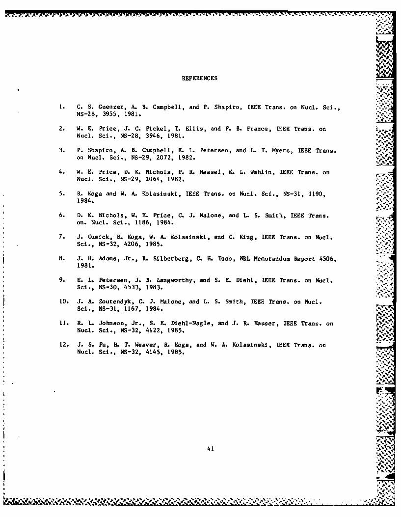
REFERENCES
I. C.S. Guenzer, A. B. Campbell, and P. Shapiro, IEEE Trans. on Nucl. Scl.,NS-28, 3955, 1981.
2. W. E. Price, J. C. Pickel, T. Ellis, and F. B. Frazee, IEEE Trans. onNucl. Sci., NS-28, 3946, 1981.
3. P. Shapiro, A. B. Campbell, E. L. Petersen, and L. T. Myers, IEEE Trans.on Nucl. Sci., NS-29, 2072, 1982.
4. W. E. Price, D. K. Nichols, P. R. Measel, K. L. Wahlin, IEEE Trans. onNucl. Sci., NS-29, 2064, 1982.
5. R. Koga and W. A. Kolasinski, IEEE Trans. on Nucl. Sci., NS-31, 1190,1984.
6. D. K. Nichols, W. E. Price, C. J. Malone, and L. S. Smith, IEEE Trans. .on. Nucl. Sci., 1186, 1984.
-... '.
7. J. Cusick, R. Koga, W. A. Kolasinski, and C. King, IEEE Trans. on Nucl.Sci., NS-32, 4206, 1985.
8. J. H. Adams, Jr., R. Sllberberg, C. H. Tsao, NRL Memorandum Report 4506,1981.
9. E. L. Petersen, J. B. Langworthy, and S. E. Diehl, IEEE Trans. on Nucl. ".Sci., NS-30, 4533, 1983.
10. J. A. Zoutendyk, C. J. Malone, and L. S. Smith, IEEE Trans. on Nucl.Sci., NS-31, 1167, 1984.
11. R. L. Johnson, Jr., S. E. Diehl-Nagle, and J. R. Hauser, IEEE Trans. onNucl. Sci., NS-32, 4122, 1985. VV
12. J. S. Fu, H. T. Weaver, R. Koga, and W. A. Kolasinski, IEEE Trans. onNucl. Sci., NS-32, 4145, 1985.
Ok
* 41
- "",.-
~~% %

% _ 7 .
LBORA, ORY OPERATIONS r
•4 .,". ,
The Aerospace Corporation functions as an "architect-engineer" for •='.
national security projects, specializing in advanced military space systems. %'
Providing research support, the corporation's Laboratory Operations conducts
experimental and theoretical investigations that focus on the application of
scientific and technical advances to such systems. Vital to the success of.. .
these investigations is the technical staff's wide-ranging expertise and its -..-'"
ability to stay current with new developments. This expertise is enhanced by . '-
a research program aimed at dealing with the many problems associated with "'"
rapidly evolving space systems. Contributing their capabilities to the -. %-
research effort are these individual laboratories: _
Aeroph~sics Laboratory: Launch vehicle and reentry fluid mechanics, heat-," -'-
transfer and flight dynamics; chemical and electric propulsion, propellant '. .chemistry, chemical dynamics, environmental chemistry, trace detection; r. ".spacecraft structural mechanics, contamination, thermal and structural °. "
control; high temperature thermomechanics, gas kinetics and radiation; cw and .;-
pulsed chemical and excimer laser development including chemical kinetics, =
spectroscopy, optical resonators, beam control, atmospheric propagation, lasereffects and countermeasures. =
Chemistry and Physics Laboratory: Atmospheric chemical reactions, .atmospheric optics, light scattering, state-specific chemical reactions and %
radiative signatures of missile plumes, sensor out-of-field-of-view rejection, %"applied laser spectroscopy, laser chemistry, laser optoelectronics, solar cell .-.
physics, battery electrochemistry, space vacuum and radiation effects on -%"
materials, lubrication and surface phenomena, thermionic emission, photo- a -
ensitive materials and detectors, atomic frequency standards, andenvironmental chemistry.
Computer Science Laboratory: Program verification, program translation, -'
performnce-sensitive system design, distributed architectures for spaceborne --.
computers, fault-tolerant computer systems, artificial intelligence, micro- % .electronics applications, communication protocols, and computer security.
Electronics Research Laboratoy: Microelectronics, sold-state device
physics, compound semiconductors, radiation hardening; electro-optics, quantum
e lectronics, solid-state lasers, opaltio s thatfon and communications;
? m~icrowave semiconductor devices, microwave/millimeter wave measurements, ,.-
diagnostics and radiometry, microwave/mill.imeter wave thermionic devices; . -atomic time and frequency standards; antennas, rf systems, electromagnetic
propagation phenomena, space communication systems.rg e te d
Materials Sciences Laboratory: Development of new materials metals, balloys, ceramics, polymers and their composites, and new forms of carbon; non-
destructive evaluation, component failure analysis and reliability; fracture
mechanics and stress corrosion; analysis and evaluation of materials at heatcryogenic and elevated temperatures as well as in space and enemy-induced
environmentsm y , n c tet
sp Space Sciences Laboratory: Magnetopheric, auroral and cosmic ray
physics, wave-particle Interactions, magnetosphertic plasma waves; atmosphericand ionospheric physics, density and composition of the upper atmosphere, 1-
remote sensing using atmospheric radiation; solar physics, infrared astronomy,
Infrared signature analysis; effects of solar activity, magnetic storms and %nuclear explosions n the earth's atmospe- sp here and magnetosphere;
effects of electromagnetic and particulate radiations on space systems; space
instrucntat ion. a a m ri n
r?-
eniomnolceity
CcPat
4, p a n s s t
coptrfuttlrn"omue ytmatfca inelgne micro- ," '-: - .-."

p4pP4
.4.
VU
2-'V
'V
-V
---- k-,'