
Event Manual - Aerospace Maintenance Council€¦ · #30 (B) Pratt & Whitney V2500 HPC 7 th Stage...
91
Event Manual The Aerospace Maintenance Council, a non-profit organization, promotes and supports the aerospace maintenance community. The council’s flagstone event, the Aerospace Maintenance Competition (AMC), recognizes and celebrates the aviation maintenance technician, and raises awareness of the knowledge and skill required to maintain safe, airworthy aircraft, worldwide. The competition is held annually in conjunction with Aviation Week’s MRO Americas. The event will take place on April 8-11 at— The Georgia World Congress Center, Building B | Halls 1-5 285 Andrew Young International Blvd NW Atlanta, GA 30313 (404) 223-4000 The purpose of this manual is to provide participants information about the competition and its competitive events. It will be revised periodically while events are added and modified, please check back often to ensure you’re referencing the most current version. Send comments and suggested revisions to [email protected].
Transcript of Event Manual - Aerospace Maintenance Council€¦ · #30 (B) Pratt & Whitney V2500 HPC 7 th Stage...

Event Manual
The Aerospace Maintenance Council, a non-profit organization, promotes and supports the aerospace maintenance community. The council’s flagstone event, the Aerospace Maintenance Competition (AMC), recognizes and celebrates the aviation maintenance technician, and raises awareness of the knowledge and skill required to maintain safe, airworthy aircraft, worldwide. The competition is held annually in conjunction with Aviation Week’s MRO Americas.
The event will take place on April 8-11 at—
The Georgia World Congress Center, Building B | Halls 1-5 285 Andrew Young International Blvd NW Atlanta, GA 30313 (404) 223-4000
The purpose of this manual is to provide participants information about the competition and its competitive events. It will be revised periodically while events are added and modified, please check back often to ensure you’re referencing the most current version.
Send comments and suggested revisions to [email protected].

Aerospace Maintenance Competition Event Manual
Page 2 of 91
This document is the property of the Aerospace Maintenance Council, it may not be reproduced without express written consent. Uncontrolled printed versions of this document are for reference only, users are responsible for verifying its currency against the master electronic version available on the AMC website.
Revision Number: 04
Original Issue Date: 12/18/2018
Revision Date: 03/28/2019
Table of Contents
About............................................................................................................................................................. 4
MRO Americas .............................................................................................................................................. 4
Hotel Accommodation .................................................................................................................................. 4
Floor Access .................................................................................................................................................. 4
Registration Hours ........................................................................................................................................ 5
Exhibit Hall Hours .......................................................................................................................................... 5
AMC Schedule of Events ............................................................................................................................... 5
Competition Rules ......................................................................................................................................... 5
Use of Alternates .......................................................................................................................................... 6
Scoring........................................................................................................................................................... 7
Sponsor and Event Setup .............................................................................................................................. 7
Shipping information .................................................................................................................................... 7
Competition Layout ...................................................................................................................................... 8
Team and Sponsor Recognition .................................................................................................................... 9
Competitor Orientation ................................................................................................................................ 9
Teams ............................................................................................................................................................ 9
Events .......................................................................................................................................................... 12
Event Schedule ............................................................................................................................................ 13
#1 8Tree and Alaska Airlines Airframe Damage Inspection .................................................................... 16
#2 Perfect Point and Ntegrity Aircraft Parts E-Drill Fastener Removal ................................................... 17
#3 Aircraft Technologies Group Sheet Metal Accuracy .......................................................................... 19
#4 Alaska Airlines External Power Receptacle Event .............................................................................. 21
#5 U.S. Air Force Flex Fluid Lines ............................................................................................................. 23
#6 Aerospace Maintenance Council Safety Wiring ................................................................................. 27
#7 Eastern Florida State Space Vehicle - Vacuum Loading Operation .................................................... 28
#8 ULTRAX Aerospace Condition-Based Intelligence (CBITM) .................................................................. 33
#9 Boeing Cable Rigging .......................................................................................................................... 34
#10 Daniels Manufacturing Corporation Electrical Troubleshooting ................................................... 37
#11 Daniels Manufacturing Corporation Safe-T-Cable ......................................................................... 39

Aerospace Maintenance Competition Event Manual
Page 3 of 91
This document is the property of the Aerospace Maintenance Council, it may not be reproduced without express written consent. Uncontrolled printed versions of this document are for reference only, users are responsible for verifying its currency against the master electronic version available on the AMC website.
Revision Number: 04
Original Issue Date: 12/18/2018
Revision Date: 03/28/2019
#12 Click Bond Adhesive-Bonded Fastener Installations ...................................................................... 41
#13 Michelin Aircraft Tires Inspection .................................................................................................. 43
#14 Alberth Aviation Wheel and Brake Removal and Installation ....................................................... 45
#15 Olympus and PPG Ultrasonic Testing ............................................................................................. 48
#16 Barfield Thermal Imaging CANCELLED ........................................................................................... 49
#17 Barfield Air Data Testing ................................................................................................................ 50
#18 Barfield Rf Antenna Testing ........................................................................................................... 51
#19 Boeing Fiber Optics ........................................................................................................................ 52
#20 Nida Corporation Power Troubleshooting ..................................................................................... 56
#21 W.L. Gore & Associates, Inc. Leading Edge & Panel Sealing .......................................................... 58
#22 American Airlines APU Burner Can ................................................................................................ 61
#23 United Fuel Tank Entry Precautions............................................................................................... 63
#24 American Airlines Pedestal ............................................................................................................ 64
#25 JetBlue University ADS-B Troubleshooting .................................................................................... 65
#26 Spectro Scientific Oil Test Analysis ................................................................................................ 66
#27 Abaris Training Composite Repair .................................................................................................. 68
#28 PPG Transparencies, Paint and Wing Sealant ................................................................................ 70
#29 FedEx Express Turbine Engine PDU Removal and Installation....................................................... 72
#30 (A) Pratt & Whitney PW1100G-JM Engine ACC Valve R/R ............................................................. 74
#30 (B) Pratt & Whitney V2500 HPC 7th Stage Bleed Valve Solenoid Test ........................................... 81
#31 Northrop Rice Aviation Training Solutions Charles E. Taylor Exam ............................................... 88
Record of Revisions ..................................................................................................................................... 89

Aerospace Maintenance Competition Event Manual
Page 4 of 91
This document is the property of the Aerospace Maintenance Council, it may not be reproduced without express written consent. Uncontrolled printed versions of this document are for reference only, users are responsible for verifying its currency against the master electronic version available on the AMC website.
Revision Number: 04
Original Issue Date: 12/18/2018
Revision Date: 03/28/2019
About
The AMC provides an opportunity for current and future maintenance professionals to showcase their abilities and see how they stack up against peers across the country. Five-member teams compete in maintenance events intended to test skill and knowledge required of an aviation maintenance technician. Teams may enter one of the following categories:
• Commercial Aviation • General Aviation • Space • Education • Military • MRO/OEM
The competition is managed by the Aerospace Maintenance Council’s AMC committee. It is supported through the generous contributions of the aerospace community. Sponsors host events, provide prizes, and make monetary contributions.
MRO Americas
The competition is held on the exhibit floor of MRO Americas, an annual gathering of aviation maintenance professionals that incorporates informative conference sessions and a showcase of new and innovative products, technologies, offerings and services. More information about the location and logistics can be found on that event’s website.
The AMC will take place at MRO Americas Booth Number 3359. The exhibit hall layout is available at https://exhibitor.mroamericas.aviationweek.com/am19/Public/eventmap.aspx?shavailable=1&shexhlist=1.
Hotel Accommodation
Aviation Week has reserved room blocks at a discounted rate for all MRO Americas participants. Reserve accommodation at https://mroamericas.aviationweek.com/en/plan-your-visit/hotel.html.
Floor Access
To access the competition area, all AMC competitors, instructors/coaches, sponsors, visitors and volunteers must register for a floor pass at https://www.eiseverywhere.com/ereg/index.php?eventid=359056&categoryid=2715282.
If completed in advance, registration is free. Individuals must be 16 years and older to register.
Only AMC competitors, instructors/coaches, sponsors, and volunteers will have early access to the show floor. AMC visitors and guests will only have access when the show floor is open to the public.
Aerospace Maintenance Competition Event Manual
Page 5 of 91
This document is the property of the Aerospace Maintenance Council, it may not be reproduced without express written consent. Uncontrolled printed versions of this document are for reference only, users are responsible for verifying its currency against the master electronic version available on the AMC website.
Revision Number: 04
Original Issue Date: 12/18/2018
Revision Date: 03/28/2019
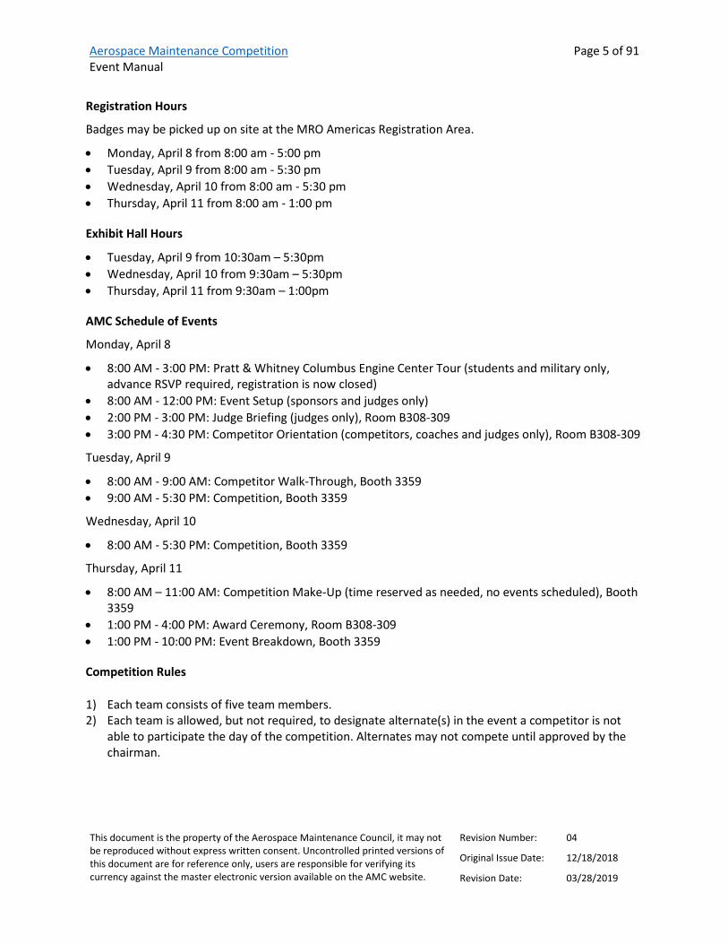
Registration Hours
Badges may be picked up on site at the MRO Americas Registration Area.
• Monday, April 8 from 8:00 am - 5:00 pm • Tuesday, April 9 from 8:00 am - 5:30 pm • Wednesday, April 10 from 8:00 am - 5:30 pm • Thursday, April 11 from 8:00 am - 1:00 pm
Exhibit Hall Hours
• Tuesday, April 9 from 10:30am – 5:30pm • Wednesday, April 10 from 9:30am – 5:30pm • Thursday, April 11 from 9:30am – 1:00pm
AMC Schedule of Events
Monday, April 8
• 8:00 AM - 3:00 PM: Pratt & Whitney Columbus Engine Center Tour (students and military only, advance RSVP required, registration is now closed)
• 8:00 AM - 12:00 PM: Event Setup (sponsors and judges only) • 2:00 PM - 3:00 PM: Judge Briefing (judges only), Room B308-309 • 3:00 PM - 4:30 PM: Competitor Orientation (competitors, coaches and judges only), Room B308-309
Tuesday, April 9
• 8:00 AM - 9:00 AM: Competitor Walk-Through, Booth 3359 • 9:00 AM - 5:30 PM: Competition, Booth 3359
Wednesday, April 10
• 8:00 AM - 5:30 PM: Competition, Booth 3359
Thursday, April 11
• 8:00 AM – 11:00 AM: Competition Make-Up (time reserved as needed, no events scheduled), Booth 3359
• 1:00 PM - 4:00 PM: Award Ceremony, Room B308-309 • 1:00 PM - 10:00 PM: Event Breakdown, Booth 3359
Competition Rules
1) Each team consists of five team members. 2) Each team is allowed, but not required, to designate alternate(s) in the event a competitor is not
able to participate the day of the competition. Alternates may not compete until approved by the chairman.

Aerospace Maintenance Competition Event Manual
Page 6 of 91
This document is the property of the Aerospace Maintenance Council, it may not be reproduced without express written consent. Uncontrolled printed versions of this document are for reference only, users are responsible for verifying its currency against the master electronic version available on the AMC website.
Revision Number: 04
Original Issue Date: 12/18/2018
Revision Date: 03/28/2019
3) Competitors must be either certificated by a national aviation authority (e.g., hold an FAA mechanic certificate), enrolled in a certificated aviation maintenance technician school, employed by a certificated repair station or manufacturing facility, or a member of the armed forces.
4) School category teams are comprised of five currently-enrolled students. Individuals that graduated the institution in the last six months that are not currently employed by an aviation-related company are also eligible to compete. Instructors are not eligible to compete.
5) Each team member must sign a release of liability to participate, completed at orientation. 6) Teams have 15 minutes to complete their assigned competitive event. All teams compete in all
events. 7) Each event has a designated number of team member(s) required to complete the task. For events
that require less than five team members, the team will assign member(s) of their choice to compete.
8) There is a five-minute break between the end of one event and the beginning of the next event. Competitors present in the five minutes preceding the event start time may review task cards, materials, or prepare for the event, as permitted by the event judge. Time will not be credited for competitors arriving after the designated start time.
9) Scores are calculated based on the standard score sheet. 10) Event sponsors provide judges for each event. Judges may stop the clock to remedy problems or
answer a question at their discretion. 11) Scores provided verbally at the completion of an event are not official until properly recorded. 12) Score grievances may be brought to the sergeant at arms during the competition and up to one half
hour after its conclusion. The AMC chairman reserves the right to modify final scores up until the awards ceremony.
13) The three teams with the lowest score in each category will be recognized at the awards ceremony. The team with the lowest score across all categories will be awarded the William F. “Bill” O’Brien Award for Excellence in Aircraft Maintenance.
14) The AMC chairman reserves the right to remove any team member(s) from the competition for, but not limited to, unprofessional behavior, cheating, etc.
15) The AMC committee reserves the right to alter events and/or rules prior to or during the competition and will make best efforts to notify all team members of the change.
16) Participants are expected to observe personal protection equipment requirements throughout the competition. Failure to observe safety practices will result in penalties.
17) All required tooling and protection equipment is provided by event sponsors. Personal tools are not allowed.
Use of Alternates
Each team will consist of five team members. Each team is allowed, but not required, to designate alternate(s) in the event a member is not able to compete the day of the competition.
The five competing team members will receive identifying wristbands at orientation and are expected to wear them at all times during the competition. In the event a team member is not able to compete

Aerospace Maintenance Competition Event Manual
Page 7 of 91
This document is the property of the Aerospace Maintenance Council, it may not be reproduced without express written consent. Uncontrolled printed versions of this document are for reference only, users are responsible for verifying its currency against the master electronic version available on the AMC website.
Revision Number: 04
Original Issue Date: 12/18/2018
Revision Date: 03/28/2019
during the event, the alternate must obtain a wristband from AMC staff before taking the place of a competing member.
Goodie bags provided at orientation for competing team members only. Only five bags per team will be distributed. Goodie bags may be offered to alternates upon availability.
Scoring
Judges will utilize the standard AMC score sheet to calculate team scores for each event. Event scores are calculated by adding the total amount of time expended to complete the event, plus penalties assessed. Standard penalties are assessed for—
• Failure to follow procedures • Improper use of tools • Unprofessionalism • Failure to properly store tools and/or equipment • Improper use of safety equipment • Incomplete or incorrect recordkeeping • Other, and provided for by the specific event or at the judge’s discretion
Any additional penalties and optional 60-second bonus opportunity specific to a particular event are detailed in the event criteria.
Sponsor and Event Setup
Sponsors will setup event and exhibit tables on Monday, April 8 from 8:00 AM to noon.
Event breakdown will take place when the exhibit floor closes, Thursday, April 11 from 1:00 PM to 10:00 PM. While tabletop materials can be broken down at the conclusion of the competition, freight items will not be picked up until Thursday afternoon. Those that plan to attend the awards ceremony taking place at 1:00 PM, may break down after its conclusion, at 4:00 PM.
All event spaces with electric needs will be pre-set with a 120V 5 Amp (500w) Single Outlet, two standard six-foot tables and two chairs. Sponsors are responsible for costs associated with any additional freight or facility needs (i.e., furniture, wireless internet, carpet, etc.). Contact [email protected] to coordinate these additional requirements.
Information regarding shipments and exhibit hall access is in the MRO Americas Exhibitor Manual available at https://mroamericas.aviationweek.com/en/exhibitor-resources1/exhibitor-resources11.html.
Shipping information
To ensure proper delivery, shipments should identify the AMC Booth #3359, and the AMC-designated event or sponsor number (for example, 3359-01, 3359-02, etc.), as provided for in this manual.

Aerospace Maintenance Competition Event Manual
Page 8 of 91
This document is the property of the Aerospace Maintenance Council, it may not be reproduced without express written consent. Uncontrolled printed versions of this document are for reference only, users are responsible for verifying its currency against the master electronic version available on the AMC website.
Revision Number: 04
Original Issue Date: 12/18/2018
Revision Date: 03/28/2019
Warehouse Shipping (for materials weighing under 5000 lbs per piece and arriving after March 7 and before March 29)—
Aerospace Maintenance Competition / Booth #3359-[Enter Event/Sponsor Table Number] MRO AMERICAS 2019 C/O Freeman 841 Joseph E Lowery Blvd NW Atlanta, GA 30318 (404) 253-6494
Show Site Shipping Address (for materials arriving after April 6 at 1:00 PM)—
Aerospace Maintenance Competition / Booth #3359-[Enter Event/Sponsor Table Number] MRO AMERICAS 2019 Georgia World Congress Center C/O Freeman 285 Andrew Young International Blvd NW Atlanta, GA 30313 (404) 253-6494
Competition Layout

Aerospace Maintenance Competition Event Manual
Page 9 of 91
This document is the property of the Aerospace Maintenance Council, it may not be reproduced without express written consent. Uncontrolled printed versions of this document are for reference only, users are responsible for verifying its currency against the master electronic version available on the AMC website.
Revision Number: 04
Original Issue Date: 12/18/2018
Revision Date: 03/28/2019
Team and Sponsor Recognition
Sponsor and team logos will be displayed on event signage and in the event program. Signage will be created and displayed at the AMC committee’s discretion. Event sponsors and those in the exhibit areas may bring company-branded table skirts and any floor and/or table signage that will fit within their designated space. Banners or flags that required hanging or rigging are prohibited.
Competitor Orientation
The briefing takes place the day before the competition begins, Monday April 8 at 3:00 PM, and is mandatory for all team members and judges. Guests are not permitted. Different from years past, the orientation will take place in Room B308-309, not on the competition floor.
One hour before the competition begins on Tuesday, April 9, competitors will have the opportunity to walk around the competition floor to get a close-up look at each event and ask further questions. If practical and as time allows, that event’s judge may offer tutorials to ensure all competitors understand the event criteria and requirements.
Teams
The AMC is able to accommodate 90 teams. Spots are available on a first come, first served basis.
Each team is assigned a team number that will be used as identifiers on the team schedule and to facilitate scoring. As of the revision date of this manual, 84 teams are confirmed to participate in the 2019 event.
No. Team Name Category 1 Airbus MRO/MFR 2 Alaska Airlines - ANC Commercial 3 Alaska Airlines - SEA Commercial 4 Alitalia Commercial 5 American Airlines - DFW Commercial 6 American Airlines - DWH MRO/MFR 7 American Airlines - TUL MRO/MFR 8 Australian Licenced Aircraft Engineers Association MRO/MFR 9 Aviation High School School
10 Aviation Institute of Maintenance - Atlanta School 11 Aviation Institute of Maintenance - Houston School 12 Boeing MRO/MFR 13 Broward College - Team 1 School 14 Broward College - Team 2 School 15 United States Air Force - 317th MXG Military 16 Elevate Aviation Military 17 Embry-Riddle University School 18 FedEx Express - INDY Commercial 19 FedEx Express - LAX MRO/MFR

Aerospace Maintenance Competition Event Manual
Page 10 of 91
This document is the property of the Aerospace Maintenance Council, it may not be reproduced without express written consent. Uncontrolled printed versions of this document are for reference only, users are responsible for verifying its currency against the master electronic version available on the AMC website.
Revision Number: 04
Original Issue Date: 12/18/2018
Revision Date: 03/28/2019
No. Team Name Category 20 HAECO Americas MRO/MFR 21 Horizon Air Commercial 22 Indian Hills Community College School 23 JetBlue Commercial 24 Jetstar - Team 1 Commercial 25 Jetstar - Team 2 Commercial 26 Liberty University School 27 Mexicana MRO MRO/MFR 28 Middle Tennessee State University - Team 1 School 29 Middle Tennessee State University - Team 2 School 30 Mohawk Valley Community College School 31 Pittsburgh Institute of Aeronautics - Hagerstown School 32 Pittsburgh Institute of Aeronautics - Myrtle Beach School 33 Pittsburgh Institute of Aeronautics - Pittsburgh School 34 Pittsburgh Institute of Aeronautics - Youngstown School 35 Pratt & Whitney - WiseMen MRO/MFR 36 Pratt & Whitney - WiseWomen MRO/MFR 37 Qantas Commercial 38 Qatar Airways Commercial 39 Republic Airline Commercial 40 Rock Valley College School 41 Royal Canadian Air Force - 4 Wing Military 42 Royal Canadian Air Force - 4 Wing 401 TFS Military 43 Royal Canadian Air Force - 435 Squadron Military 44 Royal Canadian Air Force - All Female Military 45 Royal Canadian Air Force - Search & Rescue Team Military 46 Salt Lake Community College - Team 1 School 47 Southern Illinois University Carbondale - Detail Dawgs School 48 Tarrant County College - Team 1 School 49 Tarrant County College - Team 2 School 50 TulsaTech School 51 TulsaTech Aerospace Academy School 52 United Airlines - Base Maintenance MRO/MFR 53 United Airlines - Chicago Commercial 54 United Airlines - Chix Fix Commercial 55 United Airlines - CLE Commercial 56 United States Air Force - 1 SOMXG Military 57 United States Air Force - Edwards AFB/412 Maintenance Group Military 58 United States Air Force - Fairchild Military 59 United States Air Force - McChord Military 60 United States Air Force - Ogden Air Logistics Complex Military 61 United States Air Force - OKC Air Logistics Complex - Team A Military

Aerospace Maintenance Competition Event Manual
Page 11 of 91
This document is the property of the Aerospace Maintenance Council, it may not be reproduced without express written consent. Uncontrolled printed versions of this document are for reference only, users are responsible for verifying its currency against the master electronic version available on the AMC website.
Revision Number: 04
Original Issue Date: 12/18/2018
Revision Date: 03/28/2019
No. Team Name Category 62 United States Air Force - OKC Air Logistics Complex - Team B Military 63 United States Air Force - Warner Robins Air Logistics Complex - Team 1 Military 64 United States Air Force - Warner Robins Air Logistics Complex - Team 2 Military 65 United States Air Force Reserves - 446 Aircraft Maintenance Squadron Military 66 United States Army - 128th Aviation Brigade Military 67 United States Army National Guard - CTARNG Military 68 United States Coast Guard - Aero Engineers Military 69 United States Coast Guard - Air Station Clearwater Military 70 United States Coast Guard - C-27J APO Military 71 United States Marine Corp - MAG 16 Military 72 United States Marine Corp - MALS 11 Military 73 United States Marine Corp - MALS 39 - Team 1 Military 74 United States Marine Corp - MALS 39 - Team 2 Military 75 United States Marine Corp - VMM 166 Military 76 University of the District of Columbia Community College School 77 UPS Commercial 78 Utah State University School 79 Vaughn College of Aeronautics and Technology School 80 West Los Angeles College School 81 Western Michigan University School 82 WestJet Airlines Commercial 83 WestJet Encore Commercial 84 WSU Tech School

Aerospace Maintenance Competition Event Manual
Page 12 of 91
This document is the property of the Aerospace Maintenance Council, it may not be reproduced without express written consent. Uncontrolled printed versions of this document are for reference only, users are responsible for verifying its currency against the master electronic version available on the AMC website.
Revision Number: 04
Original Issue Date: 12/18/2018
Revision Date: 03/28/2019
Events
Teams are responsible for assigning individual competitors to each event. The number of competitors required to complete each event is provided in the event grouping and in the event criteria. Description, instructions and judging criteria for each event are provided in subsequent pages of this manual. Competitors may contact judges directly with questions on a specific event.
Teams will compete in simultaneous events according to the following event group schedule:
Group Event Competitors
1 #9: Boeing Cable Rigging 2
#13: Michelin Tires Aircraft Tire Inspection 1
#22: American Airlines APU Burner Can 2
2 #20: Nida Corp Power Troubleshooting 2
#29: FedEx Turbine Engine PDU Removal and Installation 2
#31: Northrop Rice Aviation Training Solutions Charles Taylor Exam 1
3 #11: Daniels Manufacturing Corporation Safe-T-Cable 1
#17: Barfield Air Data Testing 2
#18: Barfield Rf Antenna Testing 2
4 #7: Eastern Florida State Space Vehicle - Vacuum Loading Operation 2
#10: Daniels Manufacturing Corporation Electrical Troubleshooting 2
#24: American Airlines Pedestal 1
5 #2: Perfect Point E-Drill Fastener Removal 1
#4: Alaska Airlines External Power Receptacle 2
#12: Click Bond, Inc. Adhesive-Bonded Fastener Installations 2
6 #28: PPG Aerospace Transparencies, Paint and Wing Sealant 5

Aerospace Maintenance Competition Event Manual
Page 13 of 91
This document is the property of the Aerospace Maintenance Council, it may not be reproduced without express written consent. Uncontrolled printed versions of this document are for reference only, users are responsible for verifying its currency against the master electronic version available on the AMC website.
Revision Number: 04
Original Issue Date: 12/18/2018
Revision Date: 03/28/2019
Group Event Competitors
7 #3: Aircraft Technology Group Sheet Metal Accuracy 1
#5: U.S. Air Force Flex Fluid Lines 2
#14: Alberth Aviation Wheel and Brake Removal and Installation 2
8 #1: 8Tree & Alaska Airlines Airframe Damage Inspection 2
#16: Barfield Thermal Imaging CANCELLED 2
#21: W.L. Gore & Associates, Inc. Leading Edge & Panel Sealing 3
9 #26: Spectro Scientific Oil Test Analysis 1
#27: ABARIS Composite Repair 2
#30: Pratt & Whitney ACC Valve R/R & Bleed Valve Solenoid Test 2
10 #8: ULTRAX Aerospace Condition Based Intelligence 2
#15: Olympus & PPG Aerospace Ultrasonic Testing 1
#23: United Airlines Fuel Tank Entry Precautions 2
11 #6: Aerospace Maintenance Council Safety Wiring 1
#19: Boeing Fiber Optics 2
#25: JetBlue University ADS-B Troubleshooting 2
Event Schedule
The competition consists of 15-minute stages. Two teams will complete each event group simultaneously, as indicated by the team numbers assigned in each stage and group in the schedule below.
Each team is responsible for assigning the number of individual competitors required for each event, as provided for in the event grouping, above.

Aerospace Maintenance Competition Event Manual
Page 14 of 91
This document is the property of the Aerospace Maintenance Council, it may not be reproduced without express written consent. Uncontrolled printed versions of this document are for reference only, users are responsible for verifying its currency against the master electronic version available on the AMC website.
Revision Number: 04
Original Issue Date: 12/18/2018
Revision Date: 03/28/2019
Tuesday, April 9 AM
Stage 1 Stage 2 Stage 3 Stage 4 Stage 5 Stage 6 Stage 7 Stage 8 Stage 9
Start Time 9:00 AM 9:20 AM 9:40 AM 10:00 AM 10:20 AM 10:40 AM 11:00 AM 11:20 AM 11:40 AM 11:55 AM End Time 9:15 AM 9:35 AM 9:55 AM 10:15 AM 10:35 AM 10:55 AM 11:15 AM 11:35 AM 11:55 AM 1:00 PM
Event Group 1 1 & 46 12 & 57 23 & 68 34 & 79 BREAK 11 & 56 22 & 67 33 & 78 BREAK
LUN
CH BREAK Event Group 2 2 & 47 13 & 58 24 & 69 35 & 80 1 & 46 12 & 57 23 & 68 34 & 79 BREAK Event Group 3 3 & 48 14 & 59 25 & 70 36 & 81 2 & 47 13 & 58 24 & 69 35 & 80 1 & 46 Event Group 4 4 & 49 15 & 60 26 & 71 37 & 82 3 & 48 14 & 59 25 & 70 36 & 81 2 & 47 Event Group 5 5 & 50 16 & 61 27 & 72 38 & 83 4 & 49 15 & 60 26 & 71 37 & 82 3 & 48 Event Group 6 6 & 51 17 & 62 28 & 73 39 & 84 5 & 50 16 & 61 27 & 72 38 & 83 4 & 49 Event Group 7 7 & 52 18 & 63 29 & 74 40 & 43 6 & 51 17 & 62 28 & 73 39 & 84 5 & 50 Event Group 8 8 & 53 19 & 64 30 & 75 41 & 44 7 & 52 18 & 63 29 & 74 40 & 43 6 & 51 Event Group 9 9 & 54 20 & 65 31 & 76 42 & 45 8 & 53 19 & 64 30 & 75 41 & 44 7 & 52 Event Group 10 10 & 55 21 & 66 32 & 77 BREAK 9 & 54 20 & 65 31 & 76 42 & 45 8 & 53 Event Group 11 11 & 56 22 & 67 33 & 78 BREAK 10 & 55 21 & 66 32 & 77 BREAK 9 & 54
Tuesday, April 9 PM
Stage 10 Stage 11 Stage 12 Stage 13 Stage 14 Stage 15 Stage 16 Stage 17 Stage 18 Stage 19 Stage 20 Stage 21 Stage 22 Start Time 1:00 PM 1:20 PM 1:40 PM 2:00 PM 2:20 PM 2:40 PM 3:00 PM 3:20 PM 3:40 PM 4:00 PM 4:20 PM 4:40 PM 5:00 PM
End Time 1:15 PM 1:35 PM 1:55 PM 2:15 PM 2:35 PM 2:55 PM 3:15 PM 3:35 PM 3:55 PM 4:15 PM 4:35 PM 4:55 PM 5:15 PM Event Group 1 10 & 55 21 & 66 32 & 77 BREAK 9 & 54 20 & 65 31 & 76 42 & 45 8 & 53 19 & 64 30 & 75 41 & 44 7 & 52 Event Group 2 11 & 56 22 & 67 33 & 78 BREAK 10 & 55 21 & 66 32 & 77 BREAK 9 & 54 20 & 65 31 & 76 42 & 45 8 & 53 Event Group 3 12 & 57 23 & 68 34 & 79 BREAK 11 & 56 22 & 67 33 & 78 BREAK 10 & 55 21 & 66 32 & 77 BREAK 9 & 54 Event Group 4 13 & 58 24 & 69 35 & 80 1 & 46 12 & 57 23 & 68 34 & 79 BREAK 11 & 56 22 & 67 33 & 78 BREAK 10 & 55 Event Group 5 14 & 59 25 & 70 36 & 81 2 & 47 13 & 58 24 & 69 35 & 80 1 & 46 12 & 57 23 & 68 34 & 79 BREAK 11 & 56 Event Group 6 15 & 60 26 & 71 37 & 82 3 & 48 14 & 59 25 & 70 36 & 81 2 & 47 13 & 58 24 & 69 35 & 80 1 & 46 12 & 57 Event Group 7 16 & 61 27 & 72 38 & 83 4 & 49 15 & 60 26 & 71 37 & 82 3 & 48 14 & 59 25 & 70 36 & 81 2 & 47 13 & 58 Event Group 8 17 & 62 28 & 73 39 & 84 5 & 50 16 & 61 27 & 72 38 & 83 4 & 49 15 & 60 26 & 71 37 & 82 3 & 48 14 & 59 Event Group 9 18 & 63 29 & 74 40 & 43 6 & 51 17 & 62 28 & 73 39 & 84 5 & 50 16 & 61 27 & 72 38 & 83 4 & 49 15 & 60 Event Group 10 19 & 64 30 & 75 41 & 44 7 & 52 18 & 63 29 & 74 40 & 43 6 & 51 17 & 62 28 & 73 39 & 84 5 & 50 16 & 61 Event Group 11 20 & 65 31 & 76 42 & 45 8 & 53 19 & 64 30 & 75 41 & 44 7 & 52 18 & 63 29 & 74 40 & 43 6 & 51 17 & 62

Aerospace Maintenance Competition Event Manual
Page 15 of 91
This document is the property of the Aerospace Maintenance Council, it may not be reproduced without express written consent. Uncontrolled printed versions of this document are for reference only, users are responsible for verifying its currency against the master electronic version available on the AMC website.
Revision Number: 04
Original Issue Date: 12/18/2018
Revision Date: 03/28/2019
Wednesday April 10 AM
Stage 23 Stage 24 Stage 25 Stage 26 Stage 27 Stage 28 Stage 29 Stage 30 Stage 31 Stage 32 Stage 33 Stage 34
Start Time 8:00 AM 8:20 AM 8:40 AM 9:00 AM 9:20 AM 9:40 AM 10:00 AM 10:20 AM 10:40 AM 11:00 AM 11:20 AM 11:40 AM 11:55 AM End Time 8:15 AM 8:35 AM 8:55 AM 9:15 AM 9:35 AM 9:55 AM 10:15 AM 10:35 AM 10:55 AM 11:15 AM 11:35 AM 11:55 AM 1:00 PM
Event Group 1 18 & 63 29 & 74 40 & 43 6 & 51 17 & 62 28 & 73 39 & 84 5 & 50 16 & 61 27 & 72 38 & 83 4 & 49
LUN
CH BREAK
Event Group 2 19 & 64 30 & 75 41 & 44 7 & 52 18 & 63 29 & 74 40 & 43 6 & 51 17 & 62 28 & 73 39 & 84 5 & 50 Event Group 3 20 & 65 31 & 76 42 & 45 8 & 53 19 & 64 30 & 75 41 & 44 7 & 52 18 & 63 29 & 74 40 & 43 6 & 51 Event Group 4 21 & 66 32 & 77 BREAK 9 & 54 20 & 65 31 & 76 42 & 45 8 & 53 19 & 64 30 & 75 41 & 44 7 & 52 Event Group 5 22 & 67 33 & 78 BREAK 10 & 55 21 & 66 32 & 77 BREAK 9 & 54 20 & 65 31 & 76 42 & 45 8 & 53 Event Group 6 23 & 68 34 & 79 BREAK 11 & 56 22 & 67 33 & 78 BREAK 10 & 55 21 & 66 32 & 77 BREAK 9 & 54 Event Group 7 24 & 69 35 & 80 1 & 46 12 & 57 23 & 68 34 & 79 BREAK 11 & 56 22 & 67 33 & 78 BREAK 10 & 55 Event Group 8 25 & 70 36 & 81 2 & 47 13 & 58 24 & 69 35 & 80 1 & 46 12 & 57 23 & 68 34 & 79 BREAK 11 & 56 Event Group 9 26 & 71 37 & 82 3 & 48 14 & 59 25 & 70 36 & 81 2 & 47 13 & 58 24 & 69 35 & 80 1 & 46 12 & 57 Event Group 10 27 & 72 38 & 83 4 & 49 15 & 60 26 & 71 37 & 82 3 & 48 14 & 59 25 & 70 36 & 81 2 & 47 13 & 58 Event Group 11 28 & 73 39 & 84 5 & 50 16 & 61 27 & 72 38 & 83 4 & 49 15 & 60 26 & 71 37 & 82 3 & 48 14 & 59
Wednesday April 10 PM
Stage 35 Stage 36 Stage 37 Stage 38 Stage 39 Stage 40 Stage 41 Stage 42 Stage 43 Stage 44 Stage 45 Start Time 1:00 PM 1:20 PM 1:40 PM 2:00 PM 2:20 PM 2:40 PM 3:00 PM 3:20 PM 3:40 PM 4:00 PM 4:20 PM
End Time 1:15 PM 1:35 PM 1:55 PM 2:15 PM 2:35 PM 2:55 PM 3:15 PM 3:35 PM 3:55 PM 4:15 PM 4:35 PM Event Group 1 15 & 60 26 & 71 37 & 82 3 & 48 14 & 59 25 & 70 36 & 81 2 & 47 13 & 58 24 & 69 35 & 80 Event Group 2 16 & 61 27 & 72 38 & 83 4 & 49 15 & 60 26 & 71 37 & 82 3 & 48 14 & 59 25 & 70 36 & 81 Event Group 3 17 & 62 28 & 73 39 & 84 5 & 50 16 & 61 27 & 72 38 & 83 4 & 49 15 & 60 26 & 71 37 & 82 Event Group 4 18 & 63 29 & 74 40 & 43 6 & 51 17 & 62 28 & 73 39 & 84 5 & 50 16 & 61 27 & 72 38 & 83 Event Group 5 19 & 64 30 & 75 41 & 44 7 & 52 18 & 63 29 & 74 40 & 43 6 & 51 17 & 62 28 & 73 39 & 84 Event Group 6 20 & 65 31 & 76 42 & 45 8 & 53 19 & 64 30 & 75 41 & 44 7 & 52 18 & 63 29 & 74 40 & 43 Event Group 7 21 & 66 32 & 77 BREAK 9 & 54 20 & 65 31 & 76 42 & 45 8 & 53 19 & 64 30 & 75 41 & 44 Event Group 8 22 & 67 33 & 78 BREAK 10 & 55 21 & 66 32 & 77 BREAK 9 & 54 20 & 65 31 & 76 42 & 45 Event Group 9 23 & 68 34 & 79 BREAK 11 & 56 22 & 67 33 & 78 BREAK 10 & 55 21 & 66 32 & 77 BREAK Event Group 10 24 & 69 35 & 80 1 & 46 12 & 57 23 & 68 34 & 79 BREAK 11 & 56 22 & 67 33 & 78 BREAK Event Group 11 25 & 70 36 & 81 2 & 47 13 & 58 24 & 69 35 & 80 1 & 46 12 & 57 23 & 68 34 & 79 BREAK

Aerospace Maintenance Competition Event Manual
Page 16 of 91
This document is the property of the Aerospace Maintenance Council, it may not be reproduced without express written consent. Uncontrolled printed versions of this document are for reference only, users are responsible for verifying its currency against the master electronic version available on the AMC website.
Revision Number: 04
Original Issue Date: 12/18/2018
Revision Date: 03/28/2019
Event #1 8Tree and Alaska Airlines Airframe Damage Inspection
Provided by
Contact(s)/Judge(s) Howard Chung, [email protected], 540-838-5530
Keith Li, [email protected]
Erik Klaas, [email protected]
John Mark Mines, John Robinson
Description Competitors will measure dent damages on an airframe panel using traditional methods and with the dentCHECK inspection tool. Competitors will be evaluated on the ability to follow the prescribed steps outlined in the manual.
References Task Instructions
Equipment Depth gauge, six-inch ruler, marker, flashlight, calculator, calibration block, dentCHECK inspection tool, QR codes, compact remote control
Team members required Two
Instructions Within the allocated 15 minutes, complete tasks in order:
1. Evaluate dent as per Task #1 Manual (Dent Evaluation using Traditional Method)
2. Repeat dent evaluation as per Task #2 Manual (Dent Evaluation using dentCHECK)
Bonus: If there is time remaining after the above two tasks are completed, participants may choose to evaluate additional dents.
Scoring Scores will be calculated according to the AMC score sheet.

Aerospace Maintenance Competition Event Manual
Page 17 of 91
This document is the property of the Aerospace Maintenance Council, it may not be reproduced without express written consent. Uncontrolled printed versions of this document are for reference only, users are responsible for verifying its currency against the master electronic version available on the AMC website.
Revision Number: 04
Original Issue Date: 12/18/2018
Revision Date: 03/28/2019
Event #2 Perfect Point and Ntegrity Aircraft Parts E-Drill Fastener Removal
Provided by
Contact(s)/Judge(s) Jim Becker, Director-Business Development
Sam Derenne, Technical Director
Nils Besvold, Sales and Marketing Associate, [email protected]
Description This event will test the technician’s ability and speed when removing titanium fasteners from an aircraft structure. This will require technicians to remove 5 fasteners using an E-drill from a wing flap. The Fasteners will be of a blind-bolt configuration and exact part numbers will be presented at the competition.
References Full E-drill User Guide
E-drill Training Videos
Event Detailed Instructions
Test article photos
Tools and equipment list Eye protection required. The E-drill hand tool, locating devices, punches, hammers, and consumables will be provided.
Team Members Required One

Aerospace Maintenance Competition Event Manual
Page 18 of 91
This document is the property of the Aerospace Maintenance Council, it may not be reproduced without express written consent. Uncontrolled printed versions of this document are for reference only, users are responsible for verifying its currency against the master electronic version available on the AMC website.
Revision Number: 04
Original Issue Date: 12/18/2018
Revision Date: 03/28/2019
Event #2 Perfect Point and Ntegrity Aircraft Parts E-Drill Fastener Removal
Instructions A) Using supplied reference data, remove the Qty. (5) fasteners identified on the flap. The fasteners to be removed will be marked. See references for detailed instructions on using the E-drill with blind-bolt.
B) Using a punch, sever the stem of the fastener from the head. C) Locate and remove all FOD and check the structure for damage to
the structure
Scoring Scores will be calculated according to the AMC score sheet. Additional penalties may be assessed for mis-aligning the E-drill over the fastener which results in damage to the structure, mis-handling the tool or locators, and excessive water leakage or sparking.

Aerospace Maintenance Competition Event Manual
Page 19 of 91
This document is the property of the Aerospace Maintenance Council, it may not be reproduced without express written consent. Uncontrolled printed versions of this document are for reference only, users are responsible for verifying its currency against the master electronic version available on the AMC website.
Revision Number: 04
Original Issue Date: 12/18/2018
Revision Date: 03/28/2019
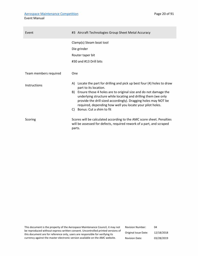
Event #3 Aircraft Technologies Group Sheet Metal Accuracy
Provided by
Contact(s)/Judge(s) Jay Logie [email protected]
Steve Kane
Description This event tests sheet metal/structures skill and accuracy for locating a part, laying out/marking holes and shims, drilling and dragging holes (as may be required) in aluminum parts.
The event will utilize a mock up nacelle to wing structure for a drag angle repair. Competitors will locate a 7” nested angle onto a drag angel per an EO dwg, which will be provided at competitor orientation.
Every job like this would be different depending on the EO, damage and access. You will have a variety of tools at your disposal to choose how you wish to proceed – access will dictate that.
References FAA Advisory Circular 43.13
Equipment Bench
Vise
Assorted Squares
6” Scale
Sharpie pen
Bull nose shears
Corded and Cordless drills
Aerospace Maintenance Competition Event Manual
Page 20 of 91
This document is the property of the Aerospace Maintenance Council, it may not be reproduced without express written consent. Uncontrolled printed versions of this document are for reference only, users are responsible for verifying its currency against the master electronic version available on the AMC website.
Revision Number: 04
Original Issue Date: 12/18/2018
Revision Date: 03/28/2019
Event #3 Aircraft Technologies Group Sheet Metal Accuracy
Clamp(s) Steam boat tool
Die grinder
Router taper bit
#30 and #13 Drill bits
Team members required One
Instructions A) Locate the part for drilling and pick up best four (4) holes to draw part to its location.
B) Ensure those 4 holes are to original size and do not damage the underlying structure while locating and drilling them (we only provide the drill sized accordingly). Dragging holes may NOT be required, depending how well you locate your pilot holes.
C) Bonus: Cut a shim to fit
Scoring Scores will be calculated according to the AMC score sheet. Penalties will be assessed for defects, required rework of a part, and scraped parts.

Aerospace Maintenance Competition Event Manual
Page 21 of 91
This document is the property of the Aerospace Maintenance Council, it may not be reproduced without express written consent. Uncontrolled printed versions of this document are for reference only, users are responsible for verifying its currency against the master electronic version available on the AMC website.
Revision Number: 04
Original Issue Date: 12/18/2018
Revision Date: 03/28/2019
Event #4 Alaska Airlines External Power Receptacle Event
Provided by
Contact(s)/Judge(s) Robert A. Long, Line/Shop Aircraft Technician, [email protected]
Ernest Yeun, Senior Engineer/AOG Engineer, [email protected]
Duane Bailey, Senior Technical Service Specialist
Ken Pitt, Engineer
Description Competitors will evaluate a discrepancy provided on a logbook sheet and determine steps for corrective action. Competitors will utilize tools to complete the task the complete appropriate paperwork.
References Task Summary
Simulator Aircraft Maintenance Manual (Rev. i)
Equipment Inspection flashlight, screw driver, wrench – hex 1/8 inch and 3/16 inch, wear gage, safety tags
Team members required Two
Instructions A) Identify the aircraft and aircraft type you are tasked to work on B) Understand the discrepancy provided on the logbook sheet and
determine planned action for corrective action

Aerospace Maintenance Competition Event Manual
Page 22 of 91
This document is the property of the Aerospace Maintenance Council, it may not be reproduced without express written consent. Uncontrolled printed versions of this document are for reference only, users are responsible for verifying its currency against the master electronic version available on the AMC website.
Revision Number: 04
Original Issue Date: 12/18/2018
Revision Date: 03/28/2019
Event #4 Alaska Airlines External Power Receptacle Event
C) Identify the appropriate sections of the Simulated Aircraft Structure (SAS) Maintenance Manual to accomplish corrective maintenance action and associated Task Cards
D) Identify components, determine effectivities, utilize tools, hardware, technical data and standard aircraft maintenance practices to complete tasks
E) Complete logbook entry filling in required areas with appropriate information
F) Consider completed task on SAS Simulator same as completed task on live aircraft
G) Tool collection and accountability H) Foreign object debris (FOD) survey within work location I) Document completion and task card completion
Scoring Scores will be calculated according to the AMC score sheet. Additional penalties may be assessed as provided for in the Alaska Skills Time Sheet.

Aerospace Maintenance Competition Event Manual
Page 23 of 91
This document is the property of the Aerospace Maintenance Council, it may not be reproduced without express written consent. Uncontrolled printed versions of this document are for reference only, users are responsible for verifying its currency against the master electronic version available on the AMC website.
Revision Number: 04
Original Issue Date: 12/18/2018
Revision Date: 03/28/2019
Event #5 U.S. Air Force Flex Fluid Lines
Provided by
Contact(s)/Judge(s) MSgt Warren Hessler, [email protected]
SSgt Travis Wilkin, [email protected]
Description Hose assembly length is 11.5 inches (“A”). Assembly length is measured from middle of b-nut flat to middle of b-nut flat. Cutoff factor for each hose end fitting is .75 inches (“C”). (See figure 6)
References None
Tools and equipment list Qty 2, 11/16 combination wrench
Qty 1, 13/16 combination wrench
Qty 1, tape measure
Qty 1, feeler gauge (0.23 - .046)
Qty 1, 3/8" dr torque wrench able to torque 190-215 in lbs.
Qty 1, 3/8" dr 11/16" crow foot.
Qty 1, hacksaw.
Qty 1, 10 pack replacement hacksaw blades. (32 TPI)
Qty, 1 diagonal cutters
Qty 1, brass pick
Qty 2, leather gloves
Team members required Two
Instructions A) Medium pressure PTFE hose buildup 1) Measure hose to required length

Aerospace Maintenance Competition Event Manual
Page 24 of 91
This document is the property of the Aerospace Maintenance Council, it may not be reproduced without express written consent. Uncontrolled printed versions of this document are for reference only, users are responsible for verifying its currency against the master electronic version available on the AMC website.
Revision Number: 04
Original Issue Date: 12/18/2018
Revision Date: 03/28/2019
Event #5 U.S. Air Force Flex Fluid Lines
2) Wrap circumference of hose with masking tape at cutoff to prevent flare out of braid **CAUTION** Do not overwrap tape
3) Cut off hose square using hack saw 4) Clamp sockets in vise.
**CAUTION** Do not overtighten vice on thin walled fittings 5) Insert neck-down end of hose into sockets using a twisting,
pushing motion until hose is through the sockets, ensuring the ends are skirt to skirt. (Figure 1). Remove tape from hose and assembly from vise
6) Separate wire braid from tube. Seal pick is provided to aide in
separation. 7) Insert sleeve between braid and outer diameter of the inner
tube **CAUTION** Do not allow wire braid to be caught between sleeve and inner tube. Do not pinch inner tube with sleeve
8) Complete positioning of sleeve by pushing sleeve against a flat surface until tube bottoms against inside sleeve diameter (Figure 3).

Aerospace Maintenance Competition Event Manual
Page 25 of 91
This document is the property of the Aerospace Maintenance Council, it may not be reproduced without express written consent. Uncontrolled printed versions of this document are for reference only, users are responsible for verifying its currency against the master electronic version available on the AMC website.
Revision Number: 04
Original Issue Date: 12/18/2018
Revision Date: 03/28/2019
Event #5 U.S. Air Force Flex Fluid Lines
9) Check tube end to make sure it is bottomed against sleeve and
wires are not trapped under sleeve. Trim excess wires as needed.
10) Clamp Nipple in vise (Note: Do not lubricate hose or nipple before insertion. Fitting components are dryfilm lubricated at time of manufacture.)
11) Size tube to sleeve by pushing hose over nipple until sleeve bottoms against nipple chamfer.
12) Check end to make sure sleeve is positioned properly. 13) Slide socket forward and thread onto nipple by hand
14) Reposition assembly by placing socket flats in vise.

Aerospace Maintenance Competition Event Manual
Page 26 of 91
This document is the property of the Aerospace Maintenance Council, it may not be reproduced without express written consent. Uncontrolled printed versions of this document are for reference only, users are responsible for verifying its currency against the master electronic version available on the AMC website.
Revision Number: 04
Original Issue Date: 12/18/2018
Revision Date: 03/28/2019
Event #5 U.S. Air Force Flex Fluid Lines
15) Tighten assembly by using a wrench on the nipple hex until
gap between socket hex and nipple hex is 1/32 inch. Gap may vary from .023 to .046 inch.
16) Repeat steps 6 through 15 for fitting on the other end. 17) Inspect hose.
B) Medium pressure PTFE hose install 1) Place hose into fixture assembly, threading coupling nuts on
by hand. 2) Torque coupling nuts 190-215 in lbs. utilizing a backup
wrench.
Figure 6.
Scoring Scores will be calculated according to the AMC score sheet.

Aerospace Maintenance Competition Event Manual
Page 27 of 91
This document is the property of the Aerospace Maintenance Council, it may not be reproduced without express written consent. Uncontrolled printed versions of this document are for reference only, users are responsible for verifying its currency against the master electronic version available on the AMC website.
Revision Number: 04
Original Issue Date: 12/18/2018
Revision Date: 03/28/2019
Event #6 Aerospace Maintenance Council Safety Wiring
Provided by
Contact(s)/Judge(s) Ken MacTiernan [email protected]
Gary McGraw
Stephen Fotoulis
Description This event will test each participant's skill and speed while accomplishing a series of safety wire patterns.
References None
Tools and equipment list Safety wire pliers, wire cutters, needle nose/duck bill pliers, and 32/1000 safety wire
Team members required One
Instructions Competitors will complete as many patterns as they can in the allotted time.
Scoring Scores will be calculated according to the AMC score sheet. Additional penalties may be assessed related to tautness of the safety wire, closeness and tightness of the pigtail to the securing hardware, and negative safety.

Aerospace Maintenance Competition Event Manual
Page 28 of 91
This document is the property of the Aerospace Maintenance Council, it may not be reproduced without express written consent. Uncontrolled printed versions of this document are for reference only, users are responsible for verifying its currency against the master electronic version available on the AMC website.
Revision Number: 04
Original Issue Date: 12/18/2018
Revision Date: 03/28/2019
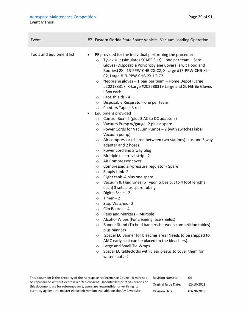
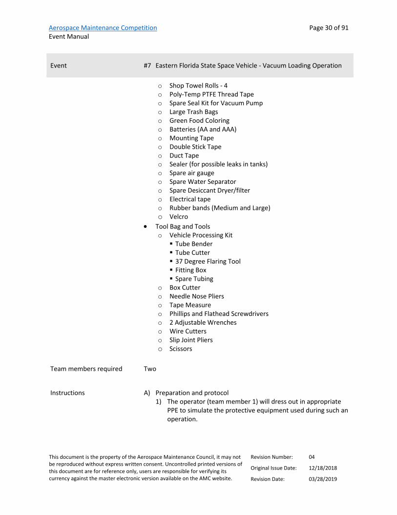
Event #7 Eastern Florida State Space Vehicle - Vacuum Loading Operation
Provided by
Contact(s)/Judge(s) Bill Fletcher, [email protected]
Description This event simulates the loading of a small quantity of a hazardous commodity from a holding tank into a space vehicle flight tank. The individual performing the procedure will be required to don the proper PPE, assemble a mobile fluid transfer station per a detailed procedure and a schematic and transfer 200 grams of a commodity (colored water) from a holding tank to a flight tank using a vacuum loading operation. A command/response protocol (see definition below) must be followed when completing the operation. Upon completion of the fluid transfer all system lines will be evacuated using compressed air (60 seconds) and disassembled from the station. (Note: The Flight Tank does not drain during line evacuation).
The QDs we are using are a push/pull type connector (explain inserting and pushing until it bottoms out and then how they have to push on the collar to get it to release the tubing). One will be available at the event table prior to the event for the technician to look at and operate to familiarize themselves on how it works.
All steps must be completed. There are no provisions for NOT PERFORMING a step or series of steps.
Definition of Command/Response Protocol- a method of communication in such a manner that the command or work instruction is read by one individual (command) and then it is repeated (response) by the person performing that work step as they complete the instruction.
References None
Aerospace Maintenance Competition Event Manual
Page 29 of 91
This document is the property of the Aerospace Maintenance Council, it may not be reproduced without express written consent. Uncontrolled printed versions of this document are for reference only, users are responsible for verifying its currency against the master electronic version available on the AMC website.
Revision Number: 04
Original Issue Date: 12/18/2018
Revision Date: 03/28/2019
Event #7 Eastern Florida State Space Vehicle - Vacuum Loading Operation
Tools and equipment list • PE provided for the individual performing the procedure o Tyvek suit (simulates SCAPE Suit) – one per team – Sara
Gloves (Disposable Polypropylene Coveralls wit Hood and Booties) 2X #13-PPW-CHB-2X-C2, X Large #13-PPW-CHB-XL-C2, Large #13-PPW-CHB-2X-LG-C2
o Neoprene gloves – 1 pair per team – Home Depot (Large #202188317, X-Large #202288319 Large and XL Nitrile Gloves I Box each
o Face shields - 4 o Disposable Respirator- one per team o Painters Tape – 3 rolls
• Equipment provided o Control Box - 2 (plus 3 AC to DC adapters) o Vacuum Pump w/gauge -2 plus a spare o Power Cords for Vacuum Pumps – 2 (with switches label
Vacuum pump) o Air compressor (shared between two stations) plus one 3 way
adapter and 2 hoses o Power cord and 3 way plug o Multiple electrical strip - 2 o Air Compressor cover o Compressed air-pressure regulator - Spare o Supply tank -2 o Flight tank -4 plus one spare o Vacuum & Fluid Lines (6 Tygon tubes cut to 4 foot lengths
each) 3 sets plus spare tubing o Digital Scale - 2 o Timer – 2 o Stop Watches - 2 o Clip Boards – 4 o Pens and Markers – Multiple o Alcohol Wipes (For cleaning face shields) o Banner Stand (To hold banners between competition tables)
plus banners o SpaceTEC Banner for bleacher area (Needs to be shipped to
AMC early so it can be placed on the bleachers). o Large and Small Tie Wraps o SpaceTEC tablecloths with clear plastic to cover them for
water spots -2
Aerospace Maintenance Competition Event Manual
Page 30 of 91
This document is the property of the Aerospace Maintenance Council, it may not be reproduced without express written consent. Uncontrolled printed versions of this document are for reference only, users are responsible for verifying its currency against the master electronic version available on the AMC website.
Revision Number: 04
Original Issue Date: 12/18/2018
Revision Date: 03/28/2019
Event #7 Eastern Florida State Space Vehicle - Vacuum Loading Operation
o Shop Towel Rolls - 4 o Poly-Temp PTFE Thread Tape o Spare Seal Kit for Vacuum Pump o Large Trash Bags o Green Food Coloring o Batteries (AA and AAA) o Mounting Tape o Double Stick Tape o Duct Tape o Sealer (for possible leaks in tanks) o Spare air gauge o Spare Water Separator o Spare Desiccant Dryer/filter o Electrical tape o Rubber bands (Medium and Large) o Velcro
• Tool Bag and Tools o Vehicle Processing Kit Tube Bender Tube Cutter 37 Degree Flaring Tool Fitting Box Spare Tubing
o Box Cutter o Needle Nose Pliers o Tape Measure o Phillips and Flathead Screwdrivers o 2 Adjustable Wrenches o Wire Cutters o Slip Joint Pliers o Scissors
Team members required Two
Instructions A) Preparation and protocol 1) The operator (team member 1) will dress out in appropriate
PPE to simulate the protective equipment used during such an operation.

Aerospace Maintenance Competition Event Manual
Page 31 of 91
This document is the property of the Aerospace Maintenance Council, it may not be reproduced without express written consent. Uncontrolled printed versions of this document are for reference only, users are responsible for verifying its currency against the master electronic version available on the AMC website.
Revision Number: 04
Original Issue Date: 12/18/2018
Revision Date: 03/28/2019
Event #7 Eastern Florida State Space Vehicle - Vacuum Loading Operation
2) Team member 2 will read out the procedure while team member 1 performs the operation. The “call and response” protocol referenced above must be used. That is, team member 2 will read out the step, and team member 1 gives an appropriate response to verify the step is complete. For example, if team member 2 reads off “close valve 1”, team member 1 would respond with “valve 1 closed” after completing the step.
B) Setup 1) Turn on power to Control Box 2) Cycle electrical valves to ensure operation (red light indicator) 3) Verify all valves (manual and electrical) are closed 4) Turn off power to the Control Box 5) Connect Vacuum and Fluid lines as shown in schematic. Note:
all fittings are push lock type. Ensure lines are pushed in all the way. The compressed air line to pressure valve will already be connected.
6) Verify all Vacuum and Fluid lines are connected as shown in schematic.
7) Verify Flight Tank is on digital scale. C) Evacuate Tank
1) Turn on power to Control Box 2) Open MV 4 3) Start Vacuum Pump 4) Open Vacuum Valve 5) Open Flight Valve 6) Open MV2 7) Evacuate system until vacuum gage reads at least 22 Hg +/- 5 8) Close Vacuum Valve 9) Close Flight Valve 10) Close MV 4 11) Turn off Vacuum pump
D) Flight Tank Load-Vacuum 1) Turn on digital scale and tare 2) Open Atmospheric Vent Valve 3) Open Supply Valve 4) Open Flight Valve and cycle valve as necessary to meter 150
grams of fluid into Flight Tank – NOTIFY JUDGE WHEN COMPLETE
5) Close all valves (manual and electric)

Aerospace Maintenance Competition Event Manual
Page 32 of 91
This document is the property of the Aerospace Maintenance Council, it may not be reproduced without express written consent. Uncontrolled printed versions of this document are for reference only, users are responsible for verifying its currency against the master electronic version available on the AMC website.
Revision Number: 04
Original Issue Date: 12/18/2018
Revision Date: 03/28/2019
Event #7 Eastern Florida State Space Vehicle - Vacuum Loading Operation
Note: If Vacuum load was unsuccessful, step 4-System Drain must be completed before restarting step 2-Evacuate Tank
E) System Drain 1) Verify all valves closed (manual and electric) 2) Verify compressed air regulator set at 20+/-5 psi 3) Open MV3 4) Open MV1 5) Open Atmospheric Vent Valve 6) Open Flight Valve 7) Open Supply Valve 8) Open Pressure Valve 9) Purge all water from system for 60 seconds (use timer
provided) Note: FLIGHT TANK DOES NOT DRAIN 10) Close Pressure Valve 11) Close Supply Valve 12) Close Flight Valve 13) Close Atmospheric Vent Valve 14) Close MV1 15) Reduce compressed air regulator to zero 16) Close MV3 17) Open MV2 to vent Flight Tank 18) Open MV1 to vent Supply Tank 19) Close all valves (manual and electric) 20) Turn Power off to Control Box
F) System Clean up 1) Verify power to vacuum pump and control box is turned off 2) Verify all valves closed 3) Disconnect all hoses between control panel and tanks (both
ends of all 6 hoses must be disconnected)
END OF EVENT
Participants should remove PPE and return it to the PPE staging table
Scoring Scores will be calculated according to the AMC score sheet. Additional penalties may be assessed for each step not completed and for each gram over/under flight tank load target

Aerospace Maintenance Competition Event Manual
Page 33 of 91
This document is the property of the Aerospace Maintenance Council, it may not be reproduced without express written consent. Uncontrolled printed versions of this document are for reference only, users are responsible for verifying its currency against the master electronic version available on the AMC website.
Revision Number: 04
Original Issue Date: 12/18/2018
Revision Date: 03/28/2019
Event #8 ULTRAX Aerospace Condition-Based Intelligence (CBITM)
Provided by
Contact(s)/Judge(s) Travis Fisher – Corporate Development, 816-595-4472 [email protected]
Matt Nimmo – Senior Technical Lead, 816-595-4448 [email protected]
Description Competitors will complete an engine service induction with a borescope inspection of the first stage compressor blades. They will use the CBITM to capture observable facts, generating accurate, actionable intelligence to distribute in their community.
References www.ultraxinc.com
https://ultraxinc.com/amc2019/
INSTRUCTIONAL VIDEO TO BE POSTED APRIL 1, 2019
Tools and equipment list All required equipment and tools will be provided by ULTRAX and available in the competition booth.
1. Mobile devices with CBI Application 2. Olympus Borescope/Videoscope – IPLEX GX
https://www.olympus-ims.com/en/rvi-products/iplex-gx/
Team members required Two
Instructions T700 Engine Service Induction with Borescope Inspection Instructions
Scoring Scores will be calculated according to the AMC score sheet.

Aerospace Maintenance Competition Event Manual
Page 34 of 91
This document is the property of the Aerospace Maintenance Council, it may not be reproduced without express written consent. Uncontrolled printed versions of this document are for reference only, users are responsible for verifying its currency against the master electronic version available on the AMC website.
Revision Number: 04
Original Issue Date: 12/18/2018
Revision Date: 03/28/2019
Event #9 Boeing Cable Rigging
Provided by
Contact(s)/Judge(s) George Thompson, Boeing Seattle Flight Test, [email protected]
Todd Warnstadt, [email protected]
Description After first flight the aileron cable rig was found to be out of tolerance. Team members will re-rig cables AA & AB.
References Table 1-3 Cable Rigging Tension (lbs)
Tensitron ACX-1 Series Digital Aircraft Cable Tension Meter Operating Instructions
Safety Turnbuckle Diagram
Tools and equipment list Tensitron Cable Tension Meter
Cable diameter gauge
Team members required Two
Instructions Warning: Check and clear aircraft and flight controls before turning on hydraulics.
A) Turn on both A&B system hydraulic switches, cycle ailerons check and install the rig pins in the captain’s wheel and the aileron control quadrant.
B) Turn off and deactivate both A&B systems hydraulics by pulling the circuit breaker for A&B system and installing the lock out collars.
Warning: Hydraulics systems must be deactivated prior to the start of any rigging operations.
C) Use the Cable diameter gauge included to easily and accurately measure cable size.
D) Record the size cable being rigged

Aerospace Maintenance Competition Event Manual
Page 35 of 91
This document is the property of the Aerospace Maintenance Council, it may not be reproduced without express written consent. Uncontrolled printed versions of this document are for reference only, users are responsible for verifying its currency against the master electronic version available on the AMC website.
Revision Number: 04
Original Issue Date: 12/18/2018
Revision Date: 03/28/2019
Event #9 Boeing Cable Rigging
E) Set up Tensitron Meter 1) Power unit on by pressing ON button. Main display will
indicate tension, material, five stored tension readings and their average, and other information.
2) Select a screen a) Move between screens by using the up (↑) and down (↓)
buttons b) Make or enter a selection by pressing the Enter/Zero
button c) Exit a setting by pressing the Escape (ESC) button.
3) Select Tension Units a) Using the up or down arrows, scroll to TENSION UNITS,
then press ENTER b) Next, select from Kilograms, DecaNewtons, or LBS, and
then press ENTER 4) Select Material
a) Using either the up or down arrows, scroll to SELECT MATERIAL, then press ENTER
b) Next scroll through the cable descriptions until the correct cable size is highlighted, then press ENTER. Your main display will indicate the cable size selected.
F) Use the tension values in Table 1-3 Cable Rigging Tension for cables AA&AB, the Tensitron meter and cable clamps adjust the cable tension to the correct value +5 / -15 lbs. for 64 F outside ambient temperature.
G) Record the required tension in lbs. per Table 1-3 H) Remove rig pins and cable clamps I) Reset Circuit breakers for the A&B system hydraulics
Warning: Check and clear aircraft and flight controls before turning on hydraulics.
J) Turn on A&B system hydraulic switches cycle the captain’s wheel, 5 times.
Note: Operate captain’s wheel gently and smoothly when cycling and returning to neutral.
K) Install Rig pins, Recheck rig load (table 1-3) of each cable and free movement of appropriate rig pins.
L) If good turn off hydraulics go to next step, if not return to step B M) Using the push/pull rod adjust the aileron to align with the mark,
after adjustments are complete, hand tighten jam nuts remove rig pins.

Aerospace Maintenance Competition Event Manual
Page 36 of 91
This document is the property of the Aerospace Maintenance Council, it may not be reproduced without express written consent. Uncontrolled printed versions of this document are for reference only, users are responsible for verifying its currency against the master electronic version available on the AMC website.
Revision Number: 04
Original Issue Date: 12/18/2018
Revision Date: 03/28/2019
Event #9 Boeing Cable Rigging
N) Safety turnbuckles per Safety Turnbuckle Diagram O) Return all tools
Notes:
No more than 3 threads may show beyond turnbuckle body. Align the slit in the barrel with the slot in the cable terminal, insert the straight end of the lock clip into the aperture formed by the aligned slots. Bring hook end of the lock clip over the hole in the center of the turnbuckle barrel and seat the hook loop into the hole by applying pressure to the hook shoulder. Repeat these steps to lock the opposite end of the turnbuckle. Both locking clips may be inserted in the same turnbuckle barrel hole, or they may be inserted in the opposite holes.
Examine both locking clips for proper engagement of the hook lip by a slight pull in the disengaging direction without the use of any tools and by visual examination to make certain that the hook lip has engaged the interior of the turnbuckle body.
Lock clips shall not be reused. The paint on the clips provides a means for determining that the clips have not been previously used.
Scoring Scores will be calculated according to the AMC score sheet.

Aerospace Maintenance Competition Event Manual
Page 37 of 91
This document is the property of the Aerospace Maintenance Council, it may not be reproduced without express written consent. Uncontrolled printed versions of this document are for reference only, users are responsible for verifying its currency against the master electronic version available on the AMC website.
Revision Number: 04
Original Issue Date: 12/18/2018
Revision Date: 03/28/2019
Event #10 Daniels Manufacturing Corporation Electrical Troubleshooting
Provided by
Contact(s)/Judge(s) Matthew Bohannon, Product Manager, [email protected]
Description Competitors will be required to find the multiple faults in a MIL-DTL-26500 connector consisting of 30 size 16 contacts using a Snap-on multi-meter. Competitors will remove the faulty wires, properly terminate contacts to a new wire, insert the new wire into both sides of the connector, check contact retention using a retention tester and continuity using a multi-meter.
References Photo 1
Photo 2
Photo 3
DMC wiring diagram
Video Tutorial
Tools and equipment list AF8 Crimp Tool
TH1A: Turret Head
DAK16B: Insertion Tool
DRK16B: Removal Tool
HT250-2: Retention Tester
67-016-01: Retention Tester Tip (socket)
68-016-01: Retention Tester Tip (pin)
Digital Multimeter: Snap-on, part number EEDM504D
22” pre-stripped wire

Aerospace Maintenance Competition Event Manual
Page 38 of 91
This document is the property of the Aerospace Maintenance Council, it may not be reproduced without express written consent. Uncontrolled printed versions of this document are for reference only, users are responsible for verifying its currency against the master electronic version available on the AMC website.
Revision Number: 04
Original Issue Date: 12/18/2018
Revision Date: 03/28/2019
Event #10 Daniels Manufacturing Corporation Electrical Troubleshooting
Contacts: M39029/31-229 (PIN), M39029/32-248 (SOCKET)
26500 Connectors: MS24264-R-24-T-30P, MS24264-R-24-T-30S
Multiple wires improperly terminated to simulate a faulty wire
Note: Competitors will be provided with a multi-meter and leads. They may not use their own equipment for this competition
Team members required Two
Instructions A) Competitors will be presented with mounted 26500 receptacles on a mock panel
B) The connector will have 30 contact cavities with size 16 contacts C) Competitors must check continuity of ALL contact cavities and find
the faulty wires using a multi-meter D) Remove the faulty wires using the proper tooling E) Competitors must assemble the crimp tools provided with the
corresponding accessory (turret head or positioner) F) The competitors must set the crimp tools to the proper crimp
settings based upon the contact part number and wire gauge G) Once properly set, the competitors will crimp a pin and socket on
the opposite ends of a 22” piece of pre-stripped wire (provided) H) Completed wire must then be inserted into the proper cavities of
the 26500 connector I) Once the new wire is inserted, the competitors must test contact
retention using a 5lb or less retention test tool J) Finally, competitors MUST test the continuity of the new wires
using a multi-meter
Scoring Scores will be calculated according to the AMC score sheet. Additional penalties may be assessed for incorrect repair of faulty wire.
Aerospace Maintenance Competition Event Manual
Page 39 of 91
This document is the property of the Aerospace Maintenance Council, it may not be reproduced without express written consent. Uncontrolled printed versions of this document are for reference only, users are responsible for verifying its currency against the master electronic version available on the AMC website.
Revision Number: 04
Original Issue Date: 12/18/2018
Revision Date: 03/28/2019
Event #11 Daniels Manufacturing Corporation Safe-T-Cable
Provided by
Contact(s)/Judge(s) Bill Randall, Strategic Accounts Manager, [email protected]
Description This event will test each participant’s skill and speed while accomplishing a series of patterns using Safe-T-Cable. The application of the safe-t-cable must maintain positive tension on the fasteners and meet the criteria for flex limits.
References Installation Instructions
Verification Equipment
Elongated Ferrules
Tools and equipment list Safety (Safe-T-Cable) Cable Gun SCTR327 (7 inch nose for .32 cable)
C10-218 Cable qty 100 .032” x 18” safety cables
F10-04 Elongated Ferrules (use where low profile bolts are present)
SCT-TB1 Torque Verification Block
3/8” drive torque wrench
Team members required One
Instructions Competitors must first verify proper function and tensioning settings of the tool by using the SCT-TB1 and a 3/8 inch drive torque wrench. Safe-T-Cable should remain in place on SCT-TB1 test block during application of the measured force.
Once verification is complete, competitors will complete as many 2 or 3 bolt patterns as they can in the allotted time. Competitors must properly thread the Safe-T-Cable through the fasteners in a manner

Aerospace Maintenance Competition Event Manual
Page 40 of 91
This document is the property of the Aerospace Maintenance Council, it may not be reproduced without express written consent. Uncontrolled printed versions of this document are for reference only, users are responsible for verifying its currency against the master electronic version available on the AMC website.
Revision Number: 04
Original Issue Date: 12/18/2018
Revision Date: 03/28/2019
Event #11 Daniels Manufacturing Corporation Safe-T-Cable
that maintains positive tension. Competitors will properly tension the Safe-T-Cable and crimp a ferrule on the end of the cable using the DMC SCTR327 rotary tool. Any excess cable/FOD must be properly disposed of after application is complete.
Scoring Scores will be calculated according to the AMC score sheet. Additional penalties may be assessed related to tautness of the safety cable and negative safety.

Aerospace Maintenance Competition Event Manual
Page 41 of 91
This document is the property of the Aerospace Maintenance Council, it may not be reproduced without express written consent. Uncontrolled printed versions of this document are for reference only, users are responsible for verifying its currency against the master electronic version available on the AMC website.
Revision Number: 04
Original Issue Date: 12/18/2018
Revision Date: 03/28/2019
Event #12 Click Bond Adhesive-Bonded Fastener Installations
Provided by
Contact(s)/Judge(s) Amy Arnold, Director Marketing & Communications, 775-885-8000 x1141, [email protected]
Rick Angell, Technical Training Manager
Moisés Valle, Applications Engineer
Ken Campitelli, Senior Program Sustainment Manager
Tim Anderson, Customer Support Engineer
Description This is a skill event using adhesive-bonded fasteners to repair wing inspection cover plates, fuel leakage cracks, and oversize bolt holes.
References Installation videos are posted to the Click Bond YouTube channel:
Surface Prep: https://www.youtube.com/watch?v=M_4b2mgMcDo
Adhesive Prep: https://www.youtube.com/watch?v=B3VjfKV0ero
Nutplate Installation: https://www.youtube.com/watch?v=Xl_zYF7l-1g
Externally Fixtured Fastener Installation:
https://www.youtube.com/watch?v=mTKAsNgogNw
Internally Fixtured Fastener Installation: https://www.youtube.com/watch?v=BtQQxUfnYHg
Printed instructions will be provided at the competition.
Tools and equipment list Gloves
Aerospace Maintenance Competition Event Manual
Page 42 of 91
This document is the property of the Aerospace Maintenance Council, it may not be reproduced without express written consent. Uncontrolled printed versions of this document are for reference only, users are responsible for verifying its currency against the master electronic version available on the AMC website.
Revision Number: 04
Original Issue Date: 12/18/2018
Revision Date: 03/28/2019
Event #12 Click Bond Adhesive-Bonded Fastener Installations
Scotch Brite abrasive pads
Solvent wipes
Adhesive
Adhesive dispensers
Mixing tips
Fasteners (nutplates, sleeves, patches)
Team members required Two
Instructions Team members will complete adhesive-bonded fastener installations:
A) Read all instructions provided before starting B) Use provided personal protection equipment C) Install adhesive-bonded fasteners as detailed in provided
instructions
Scoring Scores will be calculated according to the AMC score sheet. Additional penalties may be assessed for application of too little or too much adhesive, and/or adequate adhesive squeeze-out around fastener base.

Aerospace Maintenance Competition Event Manual
Page 43 of 91
This document is the property of the Aerospace Maintenance Council, it may not be reproduced without express written consent. Uncontrolled printed versions of this document are for reference only, users are responsible for verifying its currency against the master electronic version available on the AMC website.
Revision Number: 04
Original Issue Date: 12/18/2018
Revision Date: 03/28/2019
Event #13 Michelin Aircraft Tires Inspection
Provided by
Contact(s)/Judge(s) Jim Boyle, Aviation Technical Director – Americas, [email protected]
Description Competitors will answer inspection requirement questions and perform an airworthiness inspection of an aircraft tire including visual inspection, tire pressure reading, inspection record, and required maintenance actions.
References CYGNUS X1 Aircraft Maintenance Manual, Task 32-0000001
CYGNUS X1 Aircraft Maintenance Manual, Task 32-0000002
Michelin Aircraft Tire Care & Service Manual
Tire Inspection Form
Tools and equipment list Proper Tire Pressure Gauge
Tread Depth Gauge
Tire Inspection Form
Appropriate PSE
Flashlight
Team members required One
Instructions Competitors will be presented with a mounted and inflated aircraft tire with visible worn conditions and damages. Tire is assumed to be on-wing and stationary for 4 hours.
A) Answer the following questions: 1) How often should on-wing aircraft tires be inspected? 2) How often should on-wing aircraft tire pressures be verified? 3) How much is the pressure of an aircraft wheel/tire assembly
allowed to decrease in 24 hours? 4) What is the cause of Chevron Cutting? 5) What is the purpose of the Sidewall Vents?

Aerospace Maintenance Competition Event Manual
Page 44 of 91
This document is the property of the Aerospace Maintenance Council, it may not be reproduced without express written consent. Uncontrolled printed versions of this document are for reference only, users are responsible for verifying its currency against the master electronic version available on the AMC website.
Revision Number: 04
Original Issue Date: 12/18/2018
Revision Date: 03/28/2019
Event #13 Michelin Aircraft Tires Inspection
B) Perform visual inspection of wheel/tire assembly per job card including tread depth.
C) Record the following: 1) Tire Part Number and Size including Ply, Load and Speed Rating 2) Tire Serial Number 3) Retread Level 4) Remaining Tire Skid Depth
D) Record any noted conditions and damages on inspection form. Determine tire disposition and required actions.
E) Perform Tire Pressure Check and record readings. Determine tire disposition and required actions.
Determine what corrective actions may be required and make appropriate maintenance log entries.
Scoring Scores will be calculated according to the AMC score sheet. Additional penalties may be assessed for incorrect answers/log entries.

Aerospace Maintenance Competition Event Manual
Page 45 of 91
This document is the property of the Aerospace Maintenance Council, it may not be reproduced without express written consent. Uncontrolled printed versions of this document are for reference only, users are responsible for verifying its currency against the master electronic version available on the AMC website.
Revision Number: 04
Original Issue Date: 12/18/2018
Revision Date: 03/28/2019
Event #14 Alberth Aviation Wheel and Brake Removal and Installation
Provided by
Contact(s)/Judge(s) Ken MacTiernan [email protected]
Description This event will task the technician’s ability to remove and reinstall a mock G-IV wheel and brake assembly.
References G-IV Maintenance Manual, Chapter 32, Main Wheel Removal/Installation, Sections: 32-10-10, 32-20-10, 32-30-10 and 32-40-10
Maintenance Manual Placard
FAA Form 8130-3
Tools and equipment list None
Team members required Two
Instructions A) Main Wheel Removal 1) Ensure that Maintenance Manual Placard is on display in
cockpit before removing main wheel assembly. 2) Ensure brakes are set and Parking Brake Handle is set. 3) Ensure that nose wheels are chocked. 4) Ensure that landing gear opposite of the main gear which main
wheel assembly is to be removed from is chocked. NOTE: ONLY ONE MAIN GEAR MAY BE JACKED AT ONE TIME.
5) Install Down-Lock Pins in both main gear assemblies. Jack main gear which main wheel assembly is to be removed from. Ensure there is sufficient clearance between main wheel assembly and ramp for removal of main wheel assembly being removed. NOTE: TAKE PROPER PRECAUTIONS THAT

Aerospace Maintenance Competition Event Manual
Page 46 of 91
This document is the property of the Aerospace Maintenance Council, it may not be reproduced without express written consent. Uncontrolled printed versions of this document are for reference only, users are responsible for verifying its currency against the master electronic version available on the AMC website.
Revision Number: 04
Original Issue Date: 12/18/2018
Revision Date: 03/28/2019
Event #14 Alberth Aviation Wheel and Brake Removal and Installation
EQUIPMENT IS CLEAR OF AIRCRAFTWHILE JACKING. DAMAGE TO EQUIPMENT MAY OCCUR IF PRECAUTIONS ARENOT TAKEN.
6) Remove hub cap bolts and hub cap. Loosen main wheel main nut to finger tight. Do not remove main nut.
7) Place tire/brake dolly under main wheel assembly and raise dolly to sufficiently hold main wheel assembly. Remove main wheel nut. Slowly pull dolly away from main gear till main wheel is completely off axle.
8) Inspect axle and visible main gear assembly for any obvious damage or defects.
9) Remove main wheel assembly from dolly and fill out appropriate 8130 Tag if main wheel is to be replaced.
B) Main Wheel Installation 1) Place main wheel assembly securely on main wheel/brake
dolly and position in front of axle. 2) Slowly position main wheel assembly onto axle. Install main
wheel nut finger tight. 3) Release brakes and ensure Parking Brake Handle is not set. 4) While rotating main wheel assembly tighten main wheel nut
to a torque value of 200 In./Lbs. (+/- 10 In./Lbs.). 5) Loosen main wheel nut finger tight. Then while slowly rotating
main wheel assembly re-torque main wheel nut to a final torque of 130 In./Lbs. (+/- 10In./Lbs.). Remove main wheel/brake dolly away from aircraft. Install hub cap and torque hub cap bolts to 10 In./Lbs (+/- 0) and safety hub cap bolts.
6) Set brakes and ensure Parking Brake Handle is set. 7) Lower main gear jack. Remove and stow Down- Lock Pins from
both main gear assemblies. Chock main gear. NOTE: TAKE PROPER PRECAUTIONS THAT EQUIPMENT IS CLEAR OF AIRCRAFTWHILE LOWERING AIRCRAFT. DAMAGE TO EQUIPMENT MAY OCCUR IFPRECAUTIONS ARE NOT TAKEN.
8) Remove and stow Maintenance Manual Placard. Return aircraft to normal configuration.
C) Brake Assembly Removal 1) Remove main wheel assembly from brake position to be
removed. Reference G-IV Maintenance Manual Chapter 32 Section 32-10-10.
2) Release brakes and ensure Parking Brake Handle is not set. 3) Disconnect hydraulic lines from brake assembly.

Aerospace Maintenance Competition Event Manual
Page 47 of 91
This document is the property of the Aerospace Maintenance Council, it may not be reproduced without express written consent. Uncontrolled printed versions of this document are for reference only, users are responsible for verifying its currency against the master electronic version available on the AMC website.
Revision Number: 04
Original Issue Date: 12/18/2018
Revision Date: 03/28/2019
Event #14 Alberth Aviation Wheel and Brake Removal and Installation
4) Place main wheel/brake dolly underneath brake assembly and jack till dolly firmly supports brake assembly. Remove brake support bolts.
5) Slowly pull brake assembly away from main gear till brake assembly is completely off axle.
6) Inspect axle and visible main gear assembly for any obvious damage or defects.
7) Remove brake assembly from dolly and fill out appropriate 8130 Tag if brake assembly is to be replaced.
D) Brake Assembly Installation 1) Place brake assembly onto main wheel/brake dolly and jack till
brake assembly is at sufficient height to slide onto axle. 2) Slowly slide brake assembly till seated properly on axle. Install
brake support bolts and torque to 30 In./Lbs. (+/- 5 In./Lbs.) Lower main wheel/brake dolly till clear of brake assembly and remove dolly from aircraft.
3) Connect hydraulic lines and safety. 4) Operate hydraulics and leak check brake assembly. Ensure
there are no leaks. 5) Install Main Wheel Assembly reference Maintenance Manual
Section: 32—20-10. E) Complete an 8130 tag with the following information:
1) Part Removed: 2) Part Number Removed: 3) Part Number Installed: 4) Serial Number Removed: 5) Serial Number Installed: 6) Aircraft Tail Number Removed From: 7) Aircraft Tail Number Installed On: 8) Date Removed: 9) Removed By: 10) Installed By: 11) Station: 12) Reason for Removal:
Scoring Scores will be calculated according to the AMC score sheet.

Aerospace Maintenance Competition Event Manual
Page 48 of 91
This document is the property of the Aerospace Maintenance Council, it may not be reproduced without express written consent. Uncontrolled printed versions of this document are for reference only, users are responsible for verifying its currency against the master electronic version available on the AMC website.
Revision Number: 04
Original Issue Date: 12/18/2018
Revision Date: 03/28/2019
Event #15 Olympus and PPG Ultrasonic Testing
Provided by
Contact(s)/Judge(s) Connie Little, Product Support Engineer, PPG, [email protected]
Mike Tomasch, Business Development, Olympus [email protected]
Description The competitor will be required to calibrate an ultrasonic thickness gage and verify various acrylic panel thicknesses, then state which is the thinnest acrylic panel via results obtained from an ultrasonic thickness gage
References White Paper: Introduction to Thickness Gaging
Brochure: 45MG Ultrasonic Thickness Gage
Manual: 45MG User’s Manual
Guide: Getting Started with 45MG
Tutorial: Thickness Gage Tutorial
Tools and equipment list 45MG Ultrasonic Thickness Gage
Team members required One
Instructions Ultrasonic Thickness Testing of Acrylic Aircraft Windows Using the Olympus 45MG
Scoring Scores will be calculated according to the AMC score sheet.

Aerospace Maintenance Competition Event Manual
Page 49 of 91
This document is the property of the Aerospace Maintenance Council, it may not be reproduced without express written consent. Uncontrolled printed versions of this document are for reference only, users are responsible for verifying its currency against the master electronic version available on the AMC website.
Revision Number: 04
Original Issue Date: 12/18/2018
Revision Date: 03/28/2019
Event #16 Barfield Thermal Imaging CANCELLED
Aerospace Maintenance Competition Event Manual
Page 50 of 91
This document is the property of the Aerospace Maintenance Council, it may not be reproduced without express written consent. Uncontrolled printed versions of this document are for reference only, users are responsible for verifying its currency against the master electronic version available on the AMC website.
Revision Number: 04
Original Issue Date: 12/18/2018
Revision Date: 03/28/2019
Event #17 Barfield Air Data Testing
Provided by
Contact(s)/Judge(s) Victor Bontorno, Director Distribution & GSTE, 305-894-5408, [email protected]
Description This competition is designed to test the skills of each participating team in their understanding of and ability to troubleshoot an aircraft Pitot-Static system. Barfield recommends participants fully understand a basic aircraft Pitot-Static system and potential issues that could be found. The faults found during this procedure will test this knowledge.
References None
Tools and equipment list See procedure, linked below
Team members required Two
Instructions Test procedure 84-611-00052-150412-5 (Rev. 3-25-19)
Scoring Scores will be calculated according to the AMC score sheet. Additional penalties may be assessed for damaging indicators, not following cautions outlined in the procedure, replacing hose with incorrect parts, unnecessarily replacing a good hose, incorrectly identifying a broken indicator, or loitering in the Pitot-Static event area prior to competing.

Aerospace Maintenance Competition Event Manual
Page 51 of 91
This document is the property of the Aerospace Maintenance Council, it may not be reproduced without express written consent. Uncontrolled printed versions of this document are for reference only, users are responsible for verifying its currency against the master electronic version available on the AMC website.
Revision Number: 04
Original Issue Date: 12/18/2018
Revision Date: 03/28/2019
Event #18 Barfield Rf Antenna Testing
Provided by
Contact(s)/Judge(s) Victor Bontorno, Director Distribution & GSTE, 305-894-5408, [email protected]
Description Coaxial Cable & Antenna System Inspection with a Frequency Domain Reflectometer
References SiteHawk RF Antenna & Cable Analyzer – Aviation Test Kit 7003A001-4
Tools and equipment list P/N 7003A001-4 SiteHawk RF Aviation & Cable Analyzer – Aviation Test Kit
Team members required Two
Instructions TECHNICAL TIP Procedure (Rev. 03/25/2019)
Scoring Scores will be calculated according to the AMC score sheet.

Aerospace Maintenance Competition Event Manual
Page 52 of 91
This document is the property of the Aerospace Maintenance Council, it may not be reproduced without express written consent. Uncontrolled printed versions of this document are for reference only, users are responsible for verifying its currency against the master electronic version available on the AMC website.
Revision Number: 04
Original Issue Date: 12/18/2018
Revision Date: 03/28/2019
Event #19 Boeing Fiber Optics
Provided by
Contact(s)/Judge(s) Greg Steele, 737 Renton Preflight, [email protected]
Donald M. Rogerson
Description The MULTIMODE FIBER OPTIC LIGHT LOSS EVENT has two parts: 1) complete a practical light loss test on a fiber optic bundle and 2) answer test questions.
References 570XL 850/1300nm LED Source Brochure
560XL Fiber Optic Power Meter Datasheet
Tools and equipment list None
Team members required Two
Instructions A) PART 1: On your board you will have two reference cables that need to be mated to the light source and power meter. The ends with the ST connectors are to be mated to the meters. The other end of these cables are the LC connectors which is a push-pull connector that utilizes a retaining tab latch mechanism. There will be a fiber optic duplex bundle (cable under test) with LC connector adaptors as well as a dust cap container. Channel A can be identified with its RED heat shrink. Channel B can be identified by its BLUE heat shrink. All measurements for this event will be required to be performed at the 850nm wavelength only.

Aerospace Maintenance Competition Event Manual
Page 53 of 91
This document is the property of the Aerospace Maintenance Council, it may not be reproduced without express written consent. Uncontrolled printed versions of this document are for reference only, users are responsible for verifying its currency against the master electronic version available on the AMC website.
Revision Number: 04
Original Issue Date: 12/18/2018
Revision Date: 03/28/2019
Event #19 Boeing Fiber Optics
Whenever link loss tests are performed on fiber optic networks or cables under test, the results will be displayed on the meter with a readout in “db”. The following picture shows the initial setup that you will find on you table for this fiber optic light loss event.
1) Turn on power to both the 570XL LED source and the 560XL power meter and remove dust caps. Ensure the 570XL LED light source and the 560XL power meter are both set to 850nm wavelength. On the 560XL power meter, verify dbm is displayed. Remove dust caps from one end of each of the (2) reference cables. Place the caps in the cap storage container. Clean and mate the (2) reference cables to the 570XL LED source (850nm interface) and the 560XL power meter.
2) Take one of your LC duplex adapters, remove all of the dust caps and place them in the dust cap storage container. Remove the dust cap from one of the reference cables and place it in the storage container. Next clean the reference cable LC connector with the green cartridge cleaner and immediately insert it into one half of the LC duplex adapter until you hear an audible click.
3) Remove dust caps from the second reference cable and place it in the cap storage container. Clean this LC connector and then insert it into the LC duplex adaptor
Aerospace Maintenance Competition Event Manual
Page 54 of 91
This document is the property of the Aerospace Maintenance Council, it may not be reproduced without express written consent. Uncontrolled printed versions of this document are for reference only, users are responsible for verifying its currency against the master electronic version available on the AMC website.
Revision Number: 04
Original Issue Date: 12/18/2018
Revision Date: 03/28/2019
Event #19 Boeing Fiber Optics
so that the LC connectors are mated end face to end face.
4) Record the displayed output power of the 560XL optic power meter: _______________dbm
5) Now that you have recorded the power received in step 4, the reference cable loss can now be recorded as a reference measurement (optional) or it may be “zeroed out”(preffered). To zero out the meter, press and hold the (db/dbm) key on the 560XL power meter for approximately 3 seconds until the small ”r” annunciator appears in the bottom R/H corner and the display reads 0.00db.
6) Remove all the dust caps from the second LC duplex adapter and place them in the dust cap container. Now you are ready to perform optical measurements on the “cable under test”. With power still applied to the 560XL power meter and the 570XL LED light source, remove one of the reference cable LC connectors from the LC duplex adaptor and clean with the green cartridge cleaner. Once clean, insert it into the LC duplex adaptor until you hear an audible click.
7) Remove both dust caps off of the channel A (RED) LC connectors of the cable under test and place them in the dust cap container. Clean both the LC connectors and then insert them into the LC duplex adaptors so that both LC connectors of the reference cables and the cable under test are mated end face to end face.
8) Repeat the above procedure for channel B (BLUE) of the cable under test by cleaning the LC connectors and inserting them next to channel A (RED) in the same half of the duplex adaptors. Use the cap container and clean when necessary to avoid any penalties. METER PASS/FAIL CRITERIA: -2db OR LESS FOR A PASS/ACCEPTABLE GREATER than -2db IS A FAIL/REJECT

Aerospace Maintenance Competition Event Manual
Page 55 of 91
This document is the property of the Aerospace Maintenance Council, it may not be reproduced without express written consent. Uncontrolled printed versions of this document are for reference only, users are responsible for verifying its currency against the master electronic version available on the AMC website.
Revision Number: 04
Original Issue Date: 12/18/2018
Revision Date: 03/28/2019
Event #19 Boeing Fiber Optics
For example, a reading of -1.95db would be a pass/accept and a reading of -2.1db would be a fail/reject.
9) Read and record the optical performance/light loss of channel A (RED) ______________db. ACCEPT ___________ REJECT ________
10) Remove both reference cable LC connectors from the test adaptors, clean, and mate them with channel B (BLUE) in both test adaptors.
11) Read and record the optical performance/light loss of channel b (BLUE) _____________db. ACCEPT ___________ REJECT ________
12) MUST BE COMPLETED: Remove ALL LC connectors from test adaptors and clean them, place ALL dust caps back on ALL connections. Put ALL dust caps back in both your test adaptors and place them neatly in there storage area. Turn off both meters, then clean and cap ALL cables and cap the meters also.
13) Once finished with step 12, tell your judge “I AM FINISHED” to stop the clock.
B) When you are complete with the PART 1 PRACTICAL you may now begin the PART 2 QUESTIONS that will be provided at the competition.
Scoring Scores will be calculated according to the AMC score sheet. Additional penalties may be assessed for damaging a fiber optic cable or connector, for each time a fiber optic connector is not cleaned on the green reel cleaner after a dust cap is removed or when an LC connector is removed from the test adapter, when a judge provides assistance, or for incorrect answers.

Aerospace Maintenance Competition Event Manual
Page 56 of 91
This document is the property of the Aerospace Maintenance Council, it may not be reproduced without express written consent. Uncontrolled printed versions of this document are for reference only, users are responsible for verifying its currency against the master electronic version available on the AMC website.
Revision Number: 04
Original Issue Date: 12/18/2018
Revision Date: 03/28/2019
Event #20 Nida Corporation Power Troubleshooting
Provided by
Contact(s)/Judge(s) Robin Asplund, [email protected]
Description This event challenges the aircraft maintenance technician’s ability to troubleshoot basic aircraft power distribution systems. Contestants will be provided schematics, system descriptions and operational procedures to troubleshoot generic single engine and multi-engine power distribution systems. Scores will be based on the speed and accuracy of finding the system faults.
References Detailed contest material available at www.nida.com/amc
Tools and equipment list Multi-meters
Team members required Two
Instructions A) Single Engine Power Distribution System Troubleshooting 1) System will be operationally ready with no faults. 2) Review the pilot “write up” on the discrepancy sheet. 3) Request the first fault insertion from the judge. 4) Determine the most probable cause of the fault and the
recommended repair. 5) Sign off the pilot “write up” with your conclusion. 6) Repeat Steps 2 through 5 until all single engine aircraft faults
are completed. Only one fault will be inserted at a time. B) Multi-Engine Aircraft Power Distribution System Troubleshooting
1) Move to the multi-engine training panel
Aerospace Maintenance Competition Event Manual
Page 57 of 91
This document is the property of the Aerospace Maintenance Council, it may not be reproduced without express written consent. Uncontrolled printed versions of this document are for reference only, users are responsible for verifying its currency against the master electronic version available on the AMC website.
Revision Number: 04
Original Issue Date: 12/18/2018
Revision Date: 03/28/2019
Event #20 Nida Corporation Power Troubleshooting
2) Repeat Steps 2 – 6 above until all multi-engine aircraft faults are completed
3) Finish your paperwork and tell the judge to stop the clock.
Scoring Scores will be calculated according to the AMC score sheet. Additional penalties may be assessed for incorrect answers or unfinished scenarios.

Aerospace Maintenance Competition Event Manual
Page 58 of 91
This document is the property of the Aerospace Maintenance Council, it may not be reproduced without express written consent. Uncontrolled printed versions of this document are for reference only, users are responsible for verifying its currency against the master electronic version available on the AMC website.
Revision Number: 04
Original Issue Date: 12/18/2018
Revision Date: 03/28/2019
Event #21 W.L. Gore & Associates, Inc. Leading Edge & Panel Sealing
Provided by
Contact(s)/Judge(s) GORE™ SKYFLEX™ Aerospace Materials Team:
Jack Penick, Application Engineer [email protected]
Jon Jacobs, Application Engineer [email protected]
Gerhard Burmann, Application Engineer [email protected]
Description D-Nose Leading Edge and Access Panel installation using GORE™ SKYFLEX™ Aerospace Materials
References Installation Guide and Link to video for Installing Flat Tapes on D-Nose:
Installation Guide Tapes
Video Surface Protection – D-Nose
Installation Guide and Link to video for Installing Gaskets on Access Panel:
Installation Guide Gaskets
Video Environmental Sealant – Gasket
Tools and equipment list Scissors – Link to Scissors
Nylon Awl for punching holes – Link to Awl
Torque Wrench – One per team
Speed Handle – Two per team
Screwdriver and bits – Two per team
Rags
Team members required Three
Instructions A) D-Nose LEADING EDGE: 1) Find 700 Series GORETM SKYFLEXTM Aerospace Tapes- Part
Number GSC-21-95159-024 and ensure within shelf life.

Aerospace Maintenance Competition Event Manual
Page 59 of 91
This document is the property of the Aerospace Maintenance Council, it may not be reproduced without express written consent. Uncontrolled printed versions of this document are for reference only, users are responsible for verifying its currency against the master electronic version available on the AMC website.
Revision Number: 04
Original Issue Date: 12/18/2018
Revision Date: 03/28/2019
2) Ensure Spar and D-Nose clean and free of debris – use provided rags to wipe faying surfaces down.
3) Apply GORETM SKYFLEXTM Aerospace Tapes on Leading Edge Spar using 4 pieces of tape cut to length with scissors. The First piece should be applied along the top and the second along the bottom. Finally apply two shorter pieces to the radius and ensure 3-5mm overlap on top and bottom pieces – Figure 1.
4) See Installation Guide for Tapes and watch video in References.
5) Poke holes for each fastener in tape material with Nylon or Wood Hole Awl
6) Install Leading Edge Profile over Spar 7) Use provided speed handle / screwdriver to seat each of the
18 fasteners using a staggered pattern. 8) Use provided torque wrench to tighten each fastener to 30
in·lbs using a staggered pattern.
Figure 1: Rig – D-Nose Installation Areas in Blue
B) ACCESS PANEL 1) Find 720 Series GORETM SKYFLEXTM Aerospace Gaskets Part
Number GSC-21-96704-027 and ensure within shelf life. 2) Ensure Access Panel and Frame clean and free of debris – use
provided rag to wipe faying surfaces. 3) Apply GORETM SKYFLEXTM Aerospace Gasket on
Polycarbonate Panel shown in Figure 2 – Carefully Align fastener holes in gasket with those on the panel. Ensure gasket is placed on the correct side of the access panel. It should be

Aerospace Maintenance Competition Event Manual
Page 60 of 91
This document is the property of the Aerospace Maintenance Council, it may not be reproduced without express written consent. Uncontrolled printed versions of this document are for reference only, users are responsible for verifying its currency against the master electronic version available on the AMC website.
Revision Number: 04
Original Issue Date: 12/18/2018
Revision Date: 03/28/2019
applied to bottom of the panel. The fastener countersink is considered the top of the panel.
4) See Installation Guide for Gaskets and watch video link in References.
5) Install Panel in Opening – Gasket between frame and panel. 6) Use provided speed handle / screwdriver to seat each of the
20 fasteners using a staggered pattern. 7) Use provided torque wrench to tighten each fastener to 30
in·lbs using a staggered pattern
Scoring Scores will be calculated according to the AMC score sheet. Additional penalties may be assessed for:
• Not following work instructions – example – faying surfaces are clean, using correct part number, checking expiration date, tightening all fasteners in staggered pattern.
• Incorrect application of tapes and overlaps at D-Nose and misalignment of gasket to access panel
• Using incorrect tools
Figure 2 - Shows Gasket installed on Lexan Access panel

Aerospace Maintenance Competition Event Manual
Page 61 of 91
This document is the property of the Aerospace Maintenance Council, it may not be reproduced without express written consent. Uncontrolled printed versions of this document are for reference only, users are responsible for verifying its currency against the master electronic version available on the AMC website.
Revision Number: 04
Original Issue Date: 12/18/2018
Revision Date: 03/28/2019
Event #22 American Airlines APU Burner Can
Provided by
Contact(s)/Judge(s) Jim Gentry, B-737 Supervisor Aircraft Maintenance, American Airlines, [email protected]
Glen Phillips, Supervisor, APU and Wiring Center, [email protected]
Description Remove and Replace MD80 APU Combustion Chamber – Packing. Competitors will show inspector torques and return to zero after usage.
References IPC of APU: MD80 AMM 49-20-01-201
Tools and equipment list 1 - diagonal cutter plier
1 - 8" wire twist plier
1 - 10" wire twist plier
1 -spool of .025" safety wire
1 - 3/8" dr 7/16" deep 12pt socket
1 - 3/8" dr 9/16" crows foot
1 - 5/8 x 9/16 open end wrench
1 - 3/4 x 7/8 open end wrench
1 - 3/8" dr ratchet
1 - 3/8" dr torque wrench 40-200in lbs
1 - 48oz dead blow hammer
1 - 6" blade flat tip screwdriver

Aerospace Maintenance Competition Event Manual
Page 62 of 91
This document is the property of the Aerospace Maintenance Council, it may not be reproduced without express written consent. Uncontrolled printed versions of this document are for reference only, users are responsible for verifying its currency against the master electronic version available on the AMC website.
Revision Number: 04
Original Issue Date: 12/18/2018
Revision Date: 03/28/2019
Event #22 American Airlines APU Burner Can
Team members required Two
Instructions Remove and Replace MD80 APU Combustion Chamber Instructions
Scoring Scores will be calculated according to the AMC score sheet.

Aerospace Maintenance Competition Event Manual
Page 63 of 91
This document is the property of the Aerospace Maintenance Council, it may not be reproduced without express written consent. Uncontrolled printed versions of this document are for reference only, users are responsible for verifying its currency against the master electronic version available on the AMC website.
Revision Number: 04
Original Issue Date: 12/18/2018
Revision Date: 03/28/2019
Event #23 United Fuel Tank Entry Precautions
Provided by
Contact(s)/Judge(s) Fred Glau, Supervisor, [email protected]
Paul Davis, Lead Technician
Scotty Cole, Avionics Technician
John Vasquez, Avionics Technician
Description Competitors will defuel and refuel a 747-400 fuel tank.
References Fuel Tank Diagram
Fuel Tank SIM Photos
Grounding lug photo
Tools and equipment list Speed Handle with no 3 apex bit
Screw Driver with no 3 apex bit
0-200 in/lb torque wrench
Grease pencil
Team members required Two
Instructions Fuel tank procedures
Scoring Scores will be calculated according to the AMC score sheet.

Aerospace Maintenance Competition Event Manual
Page 64 of 91
This document is the property of the Aerospace Maintenance Council, it may not be reproduced without express written consent. Uncontrolled printed versions of this document are for reference only, users are responsible for verifying its currency against the master electronic version available on the AMC website.
Revision Number: 04
Original Issue Date: 12/18/2018
Revision Date: 03/28/2019
Event #24 American Airlines Pedestal
Provided by
Contact(s)/Judge(s) Aaron Klippel [email protected]
Ed Kempa [email protected]
Description Execute removal/replacement of MD-80 pedestal floor light.
References Removal and Replacement Instructions
Tools and equipment list See removal and replacement instructions, linked above.
Team members required One
Instructions See removal and replacement instructions, linked above.
Scoring Scores will be calculated according to the AMC score sheet.

Aerospace Maintenance Competition Event Manual
Page 65 of 91
This document is the property of the Aerospace Maintenance Council, it may not be reproduced without express written consent. Uncontrolled printed versions of this document are for reference only, users are responsible for verifying its currency against the master electronic version available on the AMC website.
Revision Number: 04
Original Issue Date: 12/18/2018
Revision Date: 03/28/2019
Event #25 JetBlue University ADS-B Troubleshooting
Provided by
Contact(s)/Judge(s) Andy Kozak, [email protected]
Description Technicians will use modern test equipment, AeroflexIFR 6000 to validate proper operation and reporting to comply with the upcoming 2020 regulations for all aircraft operating in regulated airspace. The technicians will set-up the mock aircraft to be tested and demonstrate proper testing procedures and document results for completion.
References Event overview
Tools and equipment list Electronic Flight Instrument panel set-up with GPS and Encoder simulators to represent a working modern flightdeck.
Team members required Two
Instructions The technician will fill out a task card with reported information from the IFR 6000. See linked event overview, above, for more information.
Scoring Scores will be calculated according to the AMC score sheet.

Aerospace Maintenance Competition Event Manual
Page 66 of 91
This document is the property of the Aerospace Maintenance Council, it may not be reproduced without express written consent. Uncontrolled printed versions of this document are for reference only, users are responsible for verifying its currency against the master electronic version available on the AMC website.
Revision Number: 04
Original Issue Date: 12/18/2018
Revision Date: 03/28/2019
Event #26 Spectro Scientific Oil Test Analysis
Provided by
Contact(s)/Judge(s) Randi Price [email protected]
David O'Grady david.o'[email protected]
Description This is a skill event to test the mechanics ability to successfully test an oil sample on the FieldLab 58 oil analyzer and produce a test report with automated maintenance recommendations.
References
FieldLab 58 operators manual
FieldLab 58 quick start guide
FieldLab 58 (aka Q5800) Marine Corps case study
How to run a sample video
Tools and equipment list
All the required equipment, tools and supplies are provided by Spectro Scientific in the competition booth.
• FieldLab 58 Analyzer • Consumables kit (bottle, syringe, pipette, wipes) • Printer and paper
Team members required One
Instructions
A) Select the bottle of oil sample B) Follow the instructions for running a sample through the four test
phases on the FieldLab 58 C) Produce a printed report on the printer D) Clock stops when the printer stops printing

Aerospace Maintenance Competition Event Manual
Page 67 of 91
This document is the property of the Aerospace Maintenance Council, it may not be reproduced without express written consent. Uncontrolled printed versions of this document are for reference only, users are responsible for verifying its currency against the master electronic version available on the AMC website.
Revision Number: 04
Original Issue Date: 12/18/2018
Revision Date: 03/28/2019
Event #26 Spectro Scientific Oil Test Analysis
Scoring
Scores will be calculated according to the AMC score sheet. Additional penalties may be assessed for imprecise test results and for each parameter that is more than two standard deviations from the known mean value for this sample on this analyzer.

Aerospace Maintenance Competition Event Manual
Page 68 of 91
This document is the property of the Aerospace Maintenance Council, it may not be reproduced without express written consent. Uncontrolled printed versions of this document are for reference only, users are responsible for verifying its currency against the master electronic version available on the AMC website.
Revision Number: 04
Original Issue Date: 12/18/2018
Revision Date: 03/28/2019
Event #27 Abaris Training Composite Repair
Provided by
Contact(s)/Judge(s) Corrie Volinkaty, Technical Instructor, [email protected]
Description This skills event is based on an elevated high temperature, vacuum bagged, composite repair scenario.
References Text book titled “Essentials of Advance Composite Fabrication & Repair” Available thru Aviation Supplies & Academics, Inc.’s website www.asa2fly.com
Tools and equipment list Each team will be provided a work packet which includes the Job Card, Repair Ply Material and vacuum bag. All tools & equipment needed to perform this skills event will be provided and reused by all teams including the following items; Vacuum source/hoses/ports, Heatcon Single Zone Bonder/heat blanket/thermocouples, scissors, Stanley Knife, sharpie marker, volt ohm meter, 12-inch scale, circle template, tape dispenser and calculator.
Team members required Two
Instructions A) Competitors may review the job card in the five minutes preceding the event’s official start time. Arriving at the Composite Skills Event early allows for more time to review Job Card & derive a plan of attack.
B) The Job Card can be accomplished in any order that is decided by the team, but all sign off blocks must be completed. Non-completed job cards are a frequently-cited penalty for this event so take care to sign off all blocks.
C) Repair ply material, a rectangle piece of paper, will be used for the repair plies. After drawing a 3”, 4” and 5” circle with the circle template provided, mark the warp direction by drawing a line within each circle. The short side of the repair material is the warp

Aerospace Maintenance Competition Event Manual
Page 69 of 91
This document is the property of the Aerospace Maintenance Council, it may not be reproduced without express written consent. Uncontrolled printed versions of this document are for reference only, users are responsible for verifying its currency against the master electronic version available on the AMC website.
Revision Number: 04
Original Issue Date: 12/18/2018
Revision Date: 03/28/2019
Event #27 Abaris Training Composite Repair
direction. Once cut out, follow Job Card for proper orientation of each repair ply…a cause of many deductions in the past, the Judge will be watching closely!!
D) Teams should be familiar with Ohm’s Law when given Voltage, Wattage & solving for Resistance (R = V² ÷ W). This will be used to calculate, measure & document both results on the Job Card. They also need to solve & calculate a resin mix ratio word problem…Example; Based on a given amount of total mixed epoxy resin needed, say 50 grams with a mix ratio 100:35, how many grams of Part A? How many grams of Part B? Teams will clearly write their answers on the Job Card.
E) Teams should also be familiar with vacuum bag processing. Peel ply, Bleeder, solid film, Breather materials needed for this skills challenge will be pre-cut, clearly marked and reused for all other teams. Once their repair area is vacuumed down they can start the bonder.
F) After you are done, the judge will give your time to write on the Job Card. Take a breath… & please help clean up and put the table back the way you found it. All cleanup efforts are greatly appreciated.
G) All teams must understand that these instructions are a general overview of this skills challenge & that there is a lot of detail on the Job Card, that if not followed, can lead to problems and/or unexpected deductions.
Scoring Scores will be calculated according to the AMC score sheet. Additional penalties may be assessed for items missed or a block not signed off on a job card.

Aerospace Maintenance Competition Event Manual
Page 70 of 91
This document is the property of the Aerospace Maintenance Council, it may not be reproduced without express written consent. Uncontrolled printed versions of this document are for reference only, users are responsible for verifying its currency against the master electronic version available on the AMC website.
Revision Number: 04
Original Issue Date: 12/18/2018
Revision Date: 03/28/2019
Event #28 PPG Transparencies, Paint and Wing Sealant
Provided by
Contact(s)/Judge(s) Connie Griesemer, Product Support Engineer, PPG, [email protected].
Description This is a five-part event with three separate sessions. The transparencies section will require a framing assembly repair and a Surface Seal application. The paint section will require competitors to use a Virtual Reality (VR) paint booth to simulate painting. The sealant section will require operators to perform sealing on hi-lok fasteners, dome caps and fillet sealing, both by hand and by seal caps/ use of nozzles, as well as proper mixing of semkits and manual removal of cured sealant.
References Technical data sheet for Semco® 1088 Mixer, FlexPak cartridge, Semco® 1250 Battery Gun (available on http://www.ppgaerospace.com)
Tools and equipment list See procedures, linked below
Team members required Five
Instructions Glass Plug Replacement Procedure
Semco Procedure
Surface Seal® Procedure
Virtual Reality Procedure
Sealants Procedure (provided on site)

Aerospace Maintenance Competition Event Manual
Page 71 of 91
This document is the property of the Aerospace Maintenance Council, it may not be reproduced without express written consent. Uncontrolled printed versions of this document are for reference only, users are responsible for verifying its currency against the master electronic version available on the AMC website.
Revision Number: 04
Original Issue Date: 12/18/2018
Revision Date: 03/28/2019
Scoring Scores will be calculated according to the AMC score sheet. Additional penalties may be assessed for any process errors and /or quality concerns.

Aerospace Maintenance Competition Event Manual
Page 72 of 91
This document is the property of the Aerospace Maintenance Council, it may not be reproduced without express written consent. Uncontrolled printed versions of this document are for reference only, users are responsible for verifying its currency against the master electronic version available on the AMC website.
Revision Number: 04
Original Issue Date: 12/18/2018
Revision Date: 03/28/2019
Event #29 FedEx Express Turbine Engine PDU Removal and Installation
Provided by
Contact(s)/Judge(s) Ronald Merkel, [email protected]
Description This event will test the technician’s ability to remove and install the Thrust Reverser, Pneumatic Drive Unit (PDU) on a Pratt and Whitney JT9D-7R4 turbofan engine.
References None
Tools and equipment list ¼” Drive 40-200 in lb torque wrench PN QD1R200
¼” Drive 12-Point ¼” semi-deep socket PN TMDS8
¼” Drive 12-Point 5/16” semi-deep socket PN TMDS10
¼” Drive 12-Point 7/16” semi-deep socket PN TMDS14
¼” Drive 12-Point 9/16” semi-deep socket PN TMDS18
¼” Drive 6” extension PN TMXK60
¼” Drive 14” extension PN TMXK140
¼” Drive ratchet PN T72
¼” Drive 9/16” crowfoot PN TMCO18
3/8” Drive 200 – 1000 in lb torque wrench PN QD2R1000A
3/8” Drive 12-Point ¼” shallow socket PN F081
3/8” Drive 12-Point 5/16” shallow socket PN F101
3/8” Drive 12-Point 7/16” shallow socket PN F141
3/8” Drive 12-Point 9/16” shallow socket PN F181

Aerospace Maintenance Competition Event Manual
Page 73 of 91
This document is the property of the Aerospace Maintenance Council, it may not be reproduced without express written consent. Uncontrolled printed versions of this document are for reference only, users are responsible for verifying its currency against the master electronic version available on the AMC website.
Revision Number: 04
Original Issue Date: 12/18/2018
Revision Date: 03/28/2019
Event #29 FedEx Express Turbine Engine PDU Removal and Installation
3/8” Drive 6” extension PN FXK6
3/8” Drive 11” extension PN FXK11
3/8” Drive ratchet PN F80
3/8” Drive 5/8” crowfoot PN FC020A
3/8” Drive 11/16” crowfoot PN FC022A
¼ combination wrench PN OEX8B
7/16 combination wrench PN OEX14B
9/16 combination wrench PN OEX18B
5/8 combination wrench PN OEX20B
11/16 combination wrench PN OEX22B
8-3/4” Snap-On ratcheting screw driver PN SSDMR4B
Jaw cannon plug pliers PN PWC52A
Team members required Two
Instructions JT9D Pneumatic Drive Unit – Removal/Installation Instructions
Scoring Scores will be calculated according to the AMC score sheet. Additional penalties may be assessed for failure to place PDU on table and simulate packing change, failure to show judge torque on wrench before proceeding, failure to install or secure mount bolts, failure to install, secure or torque Lines and B Nuts.

Aerospace Maintenance Competition Event Manual
Page 74 of 91
This document is the property of the Aerospace Maintenance Council, it may not be reproduced without express written consent. Uncontrolled printed versions of this document are for reference only, users are responsible for verifying its currency against the master electronic version available on the AMC website.
Revision Number: 04
Original Issue Date: 12/18/2018
Revision Date: 03/28/2019
Event #30 (A) Pratt & Whitney PW1100G-JM Engine ACC Valve R/R
Provided by
Contact(s)/Judge(s) Del Laughery [email protected]
Description The task involves the removal, inspection, and replacement of an Active Clearance Control (ACC) valve installed on the PW1100G-JM engine.
Note: This event is made up of two separate tasks. Odd-numbered teams will complete Task #30(A), even-numbered teams will complete Task #30(B) (provided in subsequent pages of this manual).
References 43.13-1B – Acceptable Methods, Techniques, and Practices – Aircraft Inspection and Repair
Tools and equipment list Electrical Connector Pliers
3/8” drive ratchet
3/8” drive 6” extension
3/8” drive, 3/8” 12 point deep well socket
11/16” open end wrench
½” open end wrench
7/8” open end wrench
Dead blow plastic hammer
6” flathead screwdriver
3/8” drive torque wrench (click type – 200-1000 in/lb)
3/8” drive torque wrench (click type – 40-200 in/lb)
3/8” drive, 7/8” crows-foot

Aerospace Maintenance Competition Event Manual
Page 75 of 91
This document is the property of the Aerospace Maintenance Council, it may not be reproduced without express written consent. Uncontrolled printed versions of this document are for reference only, users are responsible for verifying its currency against the master electronic version available on the AMC website.
Revision Number: 04
Original Issue Date: 12/18/2018
Revision Date: 03/28/2019
Event #30 (A) Pratt & Whitney PW1100G-JM Engine ACC Valve R/R
3/8” drive, 11/16” crows-foot
Lint-Free cotton cloth
Team members required Two
Instructions “This document has been publicly released.”

Aerospace Maintenance Competition Event Manual
Page 76 of 91
This document is the property of the Aerospace Maintenance Council, it may not be reproduced without express written consent. Uncontrolled printed versions of this document are for reference only, users are responsible for verifying its currency against the master electronic version available on the AMC website.
Revision Number: 04
Original Issue Date: 12/18/2018
Revision Date: 03/28/2019
Event #30 (A) Pratt & Whitney PW1100G-JM Engine ACC Valve R/R

Aerospace Maintenance Competition Event Manual
Page 77 of 91
This document is the property of the Aerospace Maintenance Council, it may not be reproduced without express written consent. Uncontrolled printed versions of this document are for reference only, users are responsible for verifying its currency against the master electronic version available on the AMC website.
Revision Number: 04
Original Issue Date: 12/18/2018
Revision Date: 03/28/2019
Event #30 (A) Pratt & Whitney PW1100G-JM Engine ACC Valve R/R

Aerospace Maintenance Competition Event Manual
Page 78 of 91
This document is the property of the Aerospace Maintenance Council, it may not be reproduced without express written consent. Uncontrolled printed versions of this document are for reference only, users are responsible for verifying its currency against the master electronic version available on the AMC website.
Revision Number: 04
Original Issue Date: 12/18/2018
Revision Date: 03/28/2019
Event #30 (A) Pratt & Whitney PW1100G-JM Engine ACC Valve R/R
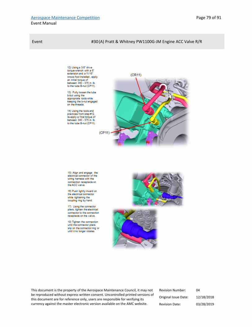
Aerospace Maintenance Competition Event Manual
Page 79 of 91
This document is the property of the Aerospace Maintenance Council, it may not be reproduced without express written consent. Uncontrolled printed versions of this document are for reference only, users are responsible for verifying its currency against the master electronic version available on the AMC website.
Revision Number: 04
Original Issue Date: 12/18/2018
Revision Date: 03/28/2019
Event #30 (A) Pratt & Whitney PW1100G-JM Engine ACC Valve R/R

Aerospace Maintenance Competition Event Manual
Page 80 of 91
This document is the property of the Aerospace Maintenance Council, it may not be reproduced without express written consent. Uncontrolled printed versions of this document are for reference only, users are responsible for verifying its currency against the master electronic version available on the AMC website.
Revision Number: 04
Original Issue Date: 12/18/2018
Revision Date: 03/28/2019
Event #30 (A) Pratt & Whitney PW1100G-JM Engine ACC Valve R/R
Scoring Scores will be calculated according to the AMC score sheet. Additional penalties may be assessed for failure to place cloth under fuel lines, failure to validate torque wrench settings with the judge before use, failure to use back-up wrenches properly to apply counter-torque, or failure to visually examine the ACC valve and report findings to the judge.

Aerospace Maintenance Competition Event Manual
Page 81 of 91
This document is the property of the Aerospace Maintenance Council, it may not be reproduced without express written consent. Uncontrolled printed versions of this document are for reference only, users are responsible for verifying its currency against the master electronic version available on the AMC website.
Revision Number: 04
Original Issue Date: 12/18/2018
Revision Date: 03/28/2019
Event #30 (B) Pratt & Whitney V2500 HPC 7th Stage Bleed Valve Solenoid Test
Provided by
Contact(s)/Judge(s) Steve Myers [email protected]
Description This is a skill event that requires utilization of engine test equipment to determine proper function of engine components.
Note: This event is made up of two separate tasks. Odd-numbered teams will complete Task #30(A), even-numbered teams will complete Task #30(B).
References V2500 HPC STAGE 7 SOLENOID VALVE 4020KS2, REMOVAL – FUNCTIONAL – TEST INSTRUCTIONS
BASIC SOLENOID TEST PROCEDURES LISTED ON TEST SET FACE PLATE
Tools and equipment list IAE 2R19437 TEST SET
11/16 COMBINATION WRENCH
¾ COMBINATION WRENCH
13/16 COMBINATION WRENCH
7/8 COMBINATION WRENCH
¼ INCH DRIVE RATCHET
¼ – 12 POINT SOCKET
¼ INCH DRIVE EXTENSION 6 INCH

Aerospace Maintenance Competition Event Manual
Page 82 of 91
This document is the property of the Aerospace Maintenance Council, it may not be reproduced without express written consent. Uncontrolled printed versions of this document are for reference only, users are responsible for verifying its currency against the master electronic version available on the AMC website.
Revision Number: 04
Original Issue Date: 12/18/2018
Revision Date: 03/28/2019
Event #30 (B) Pratt & Whitney V2500 HPC 7th Stage Bleed Valve Solenoid Test
PLYERS SOFT-JAW
11/16 CROWS FOOT ¼ DRIVE (OPEN END)
13/16 CROWS FOOT ¼ DRIVE (OPEN END)
TORQUE WRENCH 0-250 INCH POUNDS
STRAP WRENCH FOR ELECTRICAL CONNECTOR
PROTECTIVE CAPS/COVERS
Team members required Two
Instructions “This document has been publicly released.”
REMOVAL STAGE 7 SOLENOID VALVE 4020KSE
1. DISCONNECT THE HP3 AIR TUBES:
A) HP3 SUPPLY INPUT.
B) HP3 SERVO OUTPUT.
2. DISCONNECT THE ELECTRICAL CONNECTOR.
3. REMOVE HPC STAGE 7 SOLENOID VALVE:
A) REMOVE THE BOLTS & WASHERS WHICH ATTACH SOLENOID VALVE TO ENGINE BRACKET.
B) REMOVE SOLENOID VALVE.
4. INSTALL PROTECTIVE COVERS.
FUNCTIONAL TEST OF SOLENOID VALVE 4020KSE WITH TEST SET IAE2RI9437
1. INSTALLATION OF TEST SET:
A) CONNECT RED LINE TO SOLENOID VALVE SUPPLY INPUT CONNECTOR.
TORQUE TO 210 IN LBS.
Aerospace Maintenance Competition Event Manual
Page 83 of 91
This document is the property of the Aerospace Maintenance Council, it may not be reproduced without express written consent. Uncontrolled printed versions of this document are for reference only, users are responsible for verifying its currency against the master electronic version available on the AMC website.
Revision Number: 04
Original Issue Date: 12/18/2018
Revision Date: 03/28/2019
Event #30 (B) Pratt & Whitney V2500 HPC 7th Stage Bleed Valve Solenoid Test
B) CONNECT GREEN LINE TO SOLENOID VALVE SERVO OUTPUT CONNECTOR.
TORQUE TO 165 IN LBS.
2. CONNECT SOLENOID VALVE ELECTRICAL CONNECTOR WITH CABLE PROVIDED TO TEST SET.
3. PREFORM BASIC SOLENOID TEST PROCEDURES LISTED ON TEST SET FACE PLATE.
(NOTE: SOLENOID VALVE IS ALREADY CONNECTED TO TEST SET)
4. REMOVAL OF SOLENOID VALVE FROM TEST SET:
A) TURN TEST SET ELECTRICAL POWER OFF AND REMOVE ELECTRICAL CABLE.
B) REMOVE RED LINE FROM SOLENOID VALVE SUPPLY INPUT CONNECTOR.
C) REMOVE GREEN LINE FROM SOLENOID VALVE SERVO OUTPUT CONNECTOR.
INSTALLATION OF STAGE 7 SOLENOID VALVE 4020KSE
1. REMOVE PROTECTIVE COVERS FROM LINES AND ELECTRICAL CONNECTOR.
2. ATTACH THE SOLENOID VALVE TO ENGINE BRACKET WITH WASHERS AND BOLTS.
TORQUE TO 40 IN LBS.
4. INSTALL THE ELECTRICAL CONNECTOR TO THE SOLENOID VALVE
TIGHTEN CONNECTOR FULLY UNTIL RED LINE IS NO LONGER VISABLE
1. CONNECT THE HP3 AIR TUBES:
5. CONNECT THE HP3 SUPPLY LINE TO SOLENOID VALVE.
TORQUE TO 210 IN LBS.
B) CONNECT THE HP3 SERVO LINE TO SOLENOID VALVE.
TORQUE TO 165 IN LBS.

Aerospace Maintenance Competition Event Manual
Page 84 of 91
This document is the property of the Aerospace Maintenance Council, it may not be reproduced without express written consent. Uncontrolled printed versions of this document are for reference only, users are responsible for verifying its currency against the master electronic version available on the AMC website.
Revision Number: 04
Original Issue Date: 12/18/2018
Revision Date: 03/28/2019
Event #30 (B) Pratt & Whitney V2500 HPC 7th Stage Bleed Valve Solenoid Test
5. CLEAN UP AND REPLACE TOOLS.
6. INFORM JUDGE THAT EVENT IS COMPLETED.

Aerospace Maintenance Competition Event Manual
Page 85 of 91
This document is the property of the Aerospace Maintenance Council, it may not be reproduced without express written consent. Uncontrolled printed versions of this document are for reference only, users are responsible for verifying its currency against the master electronic version available on the AMC website.
Revision Number: 04
Original Issue Date: 12/18/2018
Revision Date: 03/28/2019
Event #30 (B) Pratt & Whitney V2500 HPC 7th Stage Bleed Valve Solenoid Test

Aerospace Maintenance Competition Event Manual
Page 86 of 91
This document is the property of the Aerospace Maintenance Council, it may not be reproduced without express written consent. Uncontrolled printed versions of this document are for reference only, users are responsible for verifying its currency against the master electronic version available on the AMC website.
Revision Number: 04
Original Issue Date: 12/18/2018
Revision Date: 03/28/2019
Event #30 (B) Pratt & Whitney V2500 HPC 7th Stage Bleed Valve Solenoid Test

Aerospace Maintenance Competition Event Manual
Page 87 of 91
This document is the property of the Aerospace Maintenance Council, it may not be reproduced without express written consent. Uncontrolled printed versions of this document are for reference only, users are responsible for verifying its currency against the master electronic version available on the AMC website.
Revision Number: 04
Original Issue Date: 12/18/2018
Revision Date: 03/28/2019
Event #30 (B) Pratt & Whitney V2500 HPC 7th Stage Bleed Valve Solenoid Test
Scoring Scores will be calculated according to the AMC score sheet. Additional penalties may be assessed for each step not completed, or incorrect test results.

Aerospace Maintenance Competition Event Manual
Page 88 of 91
This document is the property of the Aerospace Maintenance Council, it may not be reproduced without express written consent. Uncontrolled printed versions of this document are for reference only, users are responsible for verifying its currency against the master electronic version available on the AMC website.
Revision Number: 04
Original Issue Date: 12/18/2018
Revision Date: 03/28/2019
Event #31 Northrop Rice Aviation Training Solutions Charles E. Taylor Exam
Provided by
Contact(s)/Judge(s) Ken MacTiernan, [email protected]
Description This event will consist of multiple choice questions relating to Charles E. Taylor’s life and pioneers of aviation maintenance.
References “Charles E. Taylor 1868 – 1956 The Wright Brothers Mechanician” written by Howard R. DuFour with Peter J. Unitt, available on Amazon or at http://www.lulu.com/shop/howard-dufour-and-peter-unitt/charles-e-taylor-1868-1956-the-wright-brothers-mechanician/paperback/product-21047239.html.
“Pioneer Mechanics in Aviation” written by Giacinta Bradley Koontz, print version available at https://www.lulu.com/shop/view-cart.ep. Electronic version available at https://www.amazon.com/dp/B079FN8P7C/ref=sr_1_1?s=digital-text&ie=UTF8&qid=1517327320&sr=1-1&keywords=pioneer+mechanics+in+aviation
Tools and equipment list Tablet
Team members required One
Instructions Each designated team member will sit for a timed exam, proctored on a tablet.
Scoring Scores will be calculated based on the number of incorrect answers and unanswered questions, and the time it takes to complete the test.

Aerospace Maintenance Competition Event Manual
Page 89 of 91
This document is the property of the Aerospace Maintenance Council, it may not be reproduced without express written consent. Uncontrolled printed versions of this document are for reference only, users are responsible for verifying its currency against the master electronic version available on the AMC website.
Revision Number: 04
Original Issue Date: 12/18/2018
Revision Date: 03/28/2019
Record of Revisions
REVISION NUMBER
REVISION DATE
PAGE(S) AFFECTED REVISION DESCRIPTION
00 12/18/2018 ALL Original Issue 01 02/04/2019 47 Added linked references to PPG/Olympus event 01 02/04/2019 44 Changed Wheel and Break event from three to two competitors
01 02/04/2019 18 Added AeroSkills event 01 02/04/2019 73 Added titles to P&W event and split into two separate events.
Teams will be assigned one of the two events in subsequent versions of this manual.
01 02/04/2019 38 Added reference materials to Daniels Manufacturing Corporation Safe-T-Cable event
01 02/04/2019 36 Added video tutorial link to Daniels Manufacturing Electrical Troubleshooting event
01 02/04/2019 64 Updated description, tooling list, references, and instructions for American Airlines Pedestal event, added link to remove and replace procedures.
01 02/04/2019 11 Added event grouping 01 02/04/2019 8 Added team listing
01 02/04/2019 12 Added event schedule 01 02/04/2019 5 Revised schedule to remove competition time on Thursday, April
11, reserved for make-up events as needed.
02 02/06/2019 72 Changed the number of competitors required on the FedEx event to two (previously three), consistent with event grouping numbers as provided on page 11.
02 02/06/2019 64 Changed the number of competitors required for the American pedestal event to one (previously two), consistent with event grouping numbers as provided on page 11.
03 03/07/2019 23 Edited #5 U.S. Air Force event criteria to include tool listing and change judge contacts.
03 03/07/2019 88 Added Northrop Rice Training Solutions as #31 Charles Taylor Exam sponsor, revised judging criteria and description to indicate the test will be completed on a tablet.
03 03/07/2019 73 Update #29 FedEx event instructions (uploaded revised version), updated tooling list, revised judge criteria
03 03/07/2019 45 Added references and updated instructions for #13 Michelin Aircraft Tires Inspection

Aerospace Maintenance Competition Event Manual
Page 90 of 91
This document is the property of the Aerospace Maintenance Council, it may not be reproduced without express written consent. Uncontrolled printed versions of this document are for reference only, users are responsible for verifying its currency against the master electronic version available on the AMC website.
Revision Number: 04
Original Issue Date: 12/18/2018
Revision Date: 03/28/2019
REVISION NUMBER
REVISION DATE
PAGE(S) AFFECTED REVISION DESCRIPTION
03 03/07/2019 16 Added event criteria to #1 8tree and Alaska Airlines Airframe Damage Inspection.
03 03/07/2019 33 Updated #8 ULTRAX Condition-Based Intelligence (CBITM), revised description, added instructions.
03 03/07/2019 67 Uploaded revised criteria for #25 JetBlue University ADS-B Troubleshooting event
03 03/07/2019 43 Added additional judges to #12 Click Bond Adhesive-Bonded Fastener Installations
03 03/07/2019 17 Revised #2 Perfect Point and Ntegrity Aircraft Parts E-Drill Fastener Removal description and instructions, added new references including link to online instructions.
03 03/07/2019 75, 82 Added Pratt & Whitney event criteria to #30 (A) and (B) Tasks 03 03/07/2019 65 Revised #23 United Fuel tank task procedures 03 03/07/2019 66 Added judge email to #24 American Airlines pedestal event 03 03/07/2019 27 Added judge and contact emails to #6 AMC Safety Wiring event 03 03/07/2019 8 Added event layout
03 03/07/2019 9 Revised team list and added team numbers 03 03/07/2019 5 Added Pratt & Whitney tour opportunity to schedule, added
room numbers to orientation and judge briefing 04 03/28/2019 9 Revised team listing to remove one cancelled team and add one
newly-registered team (replaced team no. 15) 04 03/28/2019 14-15 Updated schedule to reflect 84 registered teams and regrouped
teams 40-45. Built in event group breaks for judges 04 03/28/2019 7 Revised standard score sheet to provide bonus time opportunity
for applicable events, linked to revised form in scoring section 04 03/28/2019 49 Cancelled #16 Barfield Thermal Imaging Event
04 03/28/2019 13, 16, 58 Removed #16 Barfield Thermal Imaging Event from Event Group 8. Added one additional competitor to Event #1: 8Tree & Alaska Airlines Airframe Damage Inspection (was one competitor, now two) and #21: W.L. Gore & Associates, Inc. Leading Edge & Panel Sealing (was two competitors, now three)
04 03/28/2019 50 Uploaded revised instructions for #17 Barfield Air Data Testing event, removed previous manual reference, revised description for additional penalties
04 03/28/2019 51 Added all event information to #18 Barfield Rf Antenna Testing

Aerospace Maintenance Competition Event Manual
Page 91 of 91
This document is the property of the Aerospace Maintenance Council, it may not be reproduced without express written consent. Uncontrolled printed versions of this document are for reference only, users are responsible for verifying its currency against the master electronic version available on the AMC website.
Revision Number: 04
Original Issue Date: 12/18/2018
Revision Date: 03/28/2019
REVISION NUMBER
REVISION DATE
PAGE(S) AFFECTED REVISION DESCRIPTION
04 03/28/2019 74 Added judge contacts to Pratt & Whitney events 04 03/28/2019 28 Made three revisions to #7 Eastern Florida State Space Vehicle -
Vacuum Loading Operation instructions— • Added (C)(2) Open MV 4 • Added (C)(10) Close MV 4 • Changed (D)(4) 200 grams to 150 grams
04 03/28/2019 21 Replaced #4 Alaska Airlines External Power Receptacle Event simulator aircraft maintenance manual with same manual, rev i
04 03/28/2019 23 Updated #5 U.S. Air Force Flex Fluid Lines: revised measurements in description and added figure 6
04 03/28/2019 33 Added linked set of instructions to #8 ULTRAX Aerospace Condition-Based Intelligence (CBITM)
04 03/28/2019 63 Updated #23 United Fuel Tank Entry Precautions: added a picture of the grounding lug and made minor changes to referenced instructions— • Removed verbal requirement for step 1, "Attach ground
wire" (incorporated ground lug for wire attachment) • Highlighted the verify reading levels and "Confirm for safe
Entry" in step 9
04 03/28/2019 61 Added revised instructions and tool list for #22 American Airlines APU Burner Can
04 03/28/2019 70 Added procedures for #28 PPG Transparencies, Paint and Wing Sealant event
04 03/28/2019 19 Edited description, instructions and judging criteria for #3 Aircraft Technologies Group Sheet Metal Accuracy event
04 03/28/2019 48 Add instructions for #15 Olympus and PPG Ultrasonic Testing 04 03/28/2019 72 Revised #29 FedEx Express Turbine Engine PDU Removal and
Installation instructions to remove step no. 13, added a statement that all tools must be placed in their original location prior to calling time


![HA 26.11 Simoprime A4 Catalogue V2500 [1].pdf](https://static.fdocuments.us/doc/165x107/55cf9d94550346d033ae3f15/ha-2611-simoprime-a4-catalogue-v2500-1pdf.jpg)


