Evaluation of the FreezeFree Anti-Icing System
82
Evaluation of The FreezeFree Anti-Icing System Funded by FHWA Under NAVFAC Contract No. N47408-03-D-8402 Final Report Submitted to: Paul Pisano Office of Transport.ation Operations Federal Highway Ao'rninist.ration 400 7th Street, SW lil/ashington, DC 20590 April 22 y 2005 AdL'Bncing rile Design Blld Construction Industry tllrough Illflovation
Transcript of Evaluation of the FreezeFree Anti-Icing System
Evaluation of TheFreezeFree Anti-Icing System
Funded by FHWA Under NAVFAC Contract No. N47408-03-D-8402
Final Report
Submitted to:Paul Pisano
Office of Transport.ation OperationsFederal Highway Ao'rninist.ration
400 7th Street, SWlil/ashington, DC 20590
April 22 y 2005
AdL'Bncing rile
Design Blld Construction Industry
tllrough Illflovation
(l
,
o
Civil Engineering Research Foundation
Evaluation of the FreezeFree Anti-Icing SystemFinal Report
Technical Evaluation Panel
Rick Nelson (Chair)Bill Barnhart
Dennis BurkheimerLarry Brown
Troy GilbertsonSteve Kaar
Jeffrey HallDavid KreagerMike Layman
Wayne LuptonMichele MarkotaTom Martinelli
Paul PisanoDaniel Roosvelt
Client LiaisonBarry StephensJim Crowley
CERF StaffAmar ChakerMuhammad Arner
Disclaimer: This dOCUJJJeJZt is based on }JJork supp01ted by Federal Highwqy Administration. AJryopinions, findings, conch/sions, or recomJJJendatiom e:>..pressed in this publication are those of the HighwqyImlo1Jative Technology EIJaluation Center (HITEC) of the Cilll'! Engineen'ng Research Foulldation(CERF), and do not necessati!y rqf!ed the IlieuJ ofthe Federal HighuJqy Administration.
Thz:r report is the re.wlt qf an impmtial, conJeJz.rus-based approach to ellaluatillg i111l01JC/ti1Je highuJCf)1tedJl1ology in close accordance with the HITEC Technical Protocol. The data presented are belie1Jed amlrate,C/11d the alla!yJeJ l"rc:dible. The statelJlel1ts made and l'Olzc!lIsiollJ draw11 regarding the plVdlld epC/lllated do 110t,houJe1Jer, aJJJount to C/Il endorseJJJeJZt or appr(J1)al ofthe product in gemral, orfor at!)particular applil"Cltion.
________________-F=-=in.::a::::l-=R~e::.lp:..:o:.:rt~---------------2
.._._.__._--~~~~-------
Civil Engineering Research ~oundation
Table of Contents
Page'
List of Tables and FiguresAcknowledgementsExecutive Summary
1. Introduction1.1 Background1.2 Anti-Icing of Bridge Decks and Other Problem Locations
1.2.1 The Problem1.2.2 FAST - The Proposed Solution1.2.3 Potential Benefits of FAST
1.3 Organization of the Report
2. System Information2.1 FreezeFree Basic2.2 FreezeFree Automated2.3 FreezeFree Nitro
10
14
________________-=-F.:.:in:::a::.:I~R:.:.e::Jp.::..:o:..:r:.:.t---------------_3

Civil Engineering Research Foundation
()
-4. Installation4.1 Maryland4.2 Wisconsin-K4.3 Wisconsin-R4.4 Minnesota4.5 North Dakota4.6 Oregon4.7 Summary of Ratings for System Installation
5. Operation and Maintenance5.1 Operation5.2 Maintenance5.3 Summary of Experience at the Test Sites
5.3.1 Maryland5.3.2 Wisconsin-K5.3.3 Wisconsin-R5.3.4 Minnesota5.3.5 North Dakota5.3.6 Oregon
5.4 Market Readiness5.5 Summary of Ratings for System Ope,ration & Maintenance
6. Data Collection and Analysis6.1 System Data - Adherence to Spray Logic6.2 External Data - Safety, Environmental, and Economic Benefits
32
42
61
7. Summary of Findings and Conclusions 648.1 Summary Documentation of Findings and Conclusions from the Test Sites
8.1.1 Maryland8.1.2 Wisconsin-K8.1.3 Wisconsin-R8.1.4 Minnesota8.1.5 North Dakota8.1.6 Oregon8.1.7 Key Lessons Learned
8.2 System Ratings
C)
APPENDIX-A: Selected Shop Drawings - FreezeFree System (Typical)APPENDIX-B: Data Analysis (North Dakota)
7378
________________~F~in....;a~I....:.R-e;:"lp~o:...;.rt~· 4
Civil Engineering Research Foundation
List of Tables &Figures
Table 3.1: General Information on Kenosha SiteTable 3.2: General Information on Racine SiteTable 3.3: Summary of Test Site CharacteristicsTable 5.1: Preventative Maintenance Schedule (Basic & Automated)Table 5.2: Preventative Maintenance Schedule (Nitro)Table 5.3: Performance Expectation and Market ReadinessTab.le 6.1: Summary of Analysis of Data from North Dakota SiteTable 7.1: Summary of Analysis of Data from North Dakota SiteTable 7.2: Summary of RatingsTable 7.3: Performance Expectations and Market Readiness
Page24253143435862676871
o
o
Figure A.l: Summary of Overall Rating of the System 9Figure 2.1: Pump House Assembly 15Figure 2.2: Pump Assembly 15Figure 2.3: Controller Assembly 16Figure 2.4: Spray Nozzle Assembly - Concrete Mount 17Figure 2.5: Spray Nozzle Assembly - Guardrail Mount 17Figure 2.6: Flush-Mounted Pavement Nozzle 17Figure 2.7: Pump House (Nitro) 20Figure 2.8: Pressure Tank (Nitro) 21Figure 3.1: FreezeFree Automated System Installation Site, Clarysville, Maryland 23Figure 3.2: FreezeFree Automated System Installation Site, Kenosha, Wisconsin 24Figure 3.3: FreezeFree Automated System Installation Site, Racine, Wisconsin 25Figure 3.4: FreezeFree Automated System Installation Site, Duluth, Minnesota 26Figure 3.5: FreezeFree Automated System Installation Site, Trail County, ND 27Figure 3.6: FreezeFree Automated System Installation Site, Quartz Creek Br., OR 28Figure 3.7: FreezeFree Automated System Installation Site, Los Angeles, CA 29Figure 4.1: Anecdotal Rating of System Components 32Figure 4.2: Working Conditions During System Installation 37Figure 4.3: Installation of Concrete Vault and Communication Lines 38Figure 4.4: Mounting of Support Brackets for the Conduits 38Figure 4.5: Another View of the Installation Using a Snooper Crane 39Figure 4.6: Solenoid Valve Boxes Installed at the Side of the Bridge 39Figure 4.7: Summary of System Installation Ratings 41Figure 5.1: SUl1U11ary of System Operation Ratings 59Figure 5.2: Summary of System Maintenance Ratings 60Figure 6.1: Sample Spray Logic 61Figure 7.1: Graphical Representation of Overall System Ratings 70
________________--=.F..:::;in:::.a;.:.:I;..:R:..:.e.=.ipc.0::.,:r:..:t---- 5

C)
CJ
o
c.jvi1 Eng.ineer.ing Research Foundadon
Acknowledgements
The Civil Engineering Research Foundation (CERF) wishes to acknowledge thecontributions of indiViduals whose efforts and suggestions have significantly influenced thecontent of this Highway Innovative Technology Evaluation Center (HITEC) evaluation.Notably, this study -was conducted under the guidance and review of the TechnicalEvaluation Panel, whose members volunteered to provide their insights and feedback todevelop the report. The Technical Evaluation Panel is composed of Mr. Rick J. Nelson(Chairman), Nevada DOT; Mr. Bill Barnhart, Oregon DOT; Mr. Dennis Burkheimer, IowaDOT; Mr. Larry Brown, FHWA, Mr. Troy Gilbertson, North Dakota DOT; Mr. Steve Kaar,Envirotech Central; Mr. jeffrey Hall, Minnesota DOT; Mr. David Kre,ager, City of DuluthEngineering, Minnesota; Mr. Mike Layman, Maryland SHA; Mr. Wayne Lupton, ColoradoDOT; Ms. Michele Markota, Caltrans; Mr. Tom Martinelli, Wisconsin DOT; lyfr. PaulPisano, FHWA; and Mr. Daniel Roosve1t, Virginia Transportation Research.
CERF also wishes to tllank tlle Federal Highway Administration (FHWA) for their support,cooperation and feedback during the process, and Mr. Barry Stephens and Mr. Jim Crowleyof Energy Absorption Systems for contributing to the HITEC evaluation process with theircomments and feedback.
Among the CERF staff who worked on this project, I wish to acknowledge the efforts andcontribution of Dr. Amar Chaker, Director, Engineering Applications, and Mr. MuhammadAmer, Senior Program Manager.
Michael M. GoodeVice President, Civil Engineering Research Foundation
Final Report 6

n
()
o
Civil Engineering Research Foundation
Executive Sun~mary
Background ,The Highway Innovative Technology Evaluation Center (HITEC) of the Civil EngineeringResearch Foundation (CERF), with support from the Federal Highway Administration(FHWA), conducted a multiyear study to evaluate the performance of FreezeFree™ fIxedautomated anti-icing spray system. The study was conducted by documenting the experienceof users of the system at six (6) different test sites1 located in the states of Maryland,Wisconsin (two test sites), Minnesota, North Dakota, and Oregon, and by studying andanalyzing the data obtained from these sites.
The FreezeFree system applies calibrated amounts of anti-icing liquids on ta;rgeted areas andhigh-incident locations. To trigger the spraying cycle, highway personnel can either activatethe system manually or allow the system to use its pavement sensor and Road WeatherInformation System (RWIS) to monitor ambient conditions and the road surface, and thenautomatically activate a pump and a series of high-pressure valves that spray anti-icing liquidover the targeted area in a pre-determined sequence. The system's computer makes a recordof the conditions and other information, including the date and time of activation. Tosupervise and evaluate the system's performance, offIcials can retrieve data or monitor thesystem via telephone, fax, or computer.
Limitations of the StudyThe FreezeFree systems installed on various sites were for the most part, unique. TIllsuniqueness existed in terms of the type of system such as Basic, Automated, or Nitro, typeof sensor (active or passive), types of nozzles, and so forth. This diversity of system features,on the one hand, was useful in representing the various features and possible confIgurationsof the system, but on the other hand, made it diffIcult to compare system performance fromone site to another. In addition, repairs and upgrades of the system on an ongoing basismade it diffIcult to "lock" the various parameters within a system for the purpose ofmonitoring performance over time of a given confIguration at any given site.
In addition to the evolving nature of the system during the course of thc evaluation, theother important limitation of the study is that it attempts to qualitatively summarize theexperience of system users at each of the test sites by assigning an anecdotal rating to thesystem. While such overall qualitative assessment is very useful in providing a snapshot ofuser experience, it is important to note that the criteria of assignment of such ratings canvary from user to user, depcnding on the personality, expcctations, perception, andunderstanding of each user. Moreover, outside factors such as the level of cooperation andresponse received from d1e local FreezeFrce represcntativcs can also impact d1C assignmcntof thesc ratings from one site to another.
Lasdy, due to the unavailability of data, an assessmcnt of the safety, environmental, andecononllc benefits of d1e system was not possible. Also, whilc system activation data was
1 There is a test site in California that was intended for use in this evaluation, but was not included since theinstallation at that site was not complete at the time of publication of this report.
________________--=-F..::in=a::.:l~R~e.=.JpL:..o::.:rt:.:......-----__....:.._ _:__--- 7
.-

(;
(J
o
Civil Engineerihg Researc.h Foundation
available from most sites, the ability to confml1 an actual- spray application was limited.Hence, a deterministic conclusion on system activation errors was made based on limitedinformation.
Key Lessons LearnedThe key lessons learned from this evaluation study include:
1. The FreezeFree system is not an off-thc-shelf system that can be purchased andinstalled right away at any given site. It requires customization of the installation at eachsite after studying the site requirements and conditions, and designing a specific systemand its installation to meet those requirements.
2. Selection of the proper site for the installation of the system is key to obtaining themaximum benefit out of the system. The site should have unique characteristics like highcrash history, sharp horizontal curve and/or vertical gradient change, remote locationaway from the regular maintenance routine, etc.
3. The type· and quality of the anti-icing liquid used can significantly affect theperformance of the system, particularly, the presence and p~rity of rust inhibitors.
4. The system can be most effective under frost conditions. It should not be expected toenhance safety under moderate to heavy snow conditions.
5. The installation and maintenance of the system is fairly simple. Apart from someisolated problems tl1at have been documented in this report, the installation andmaintenance requirements generally met the expectations of tl1e users.
6. There were a number of problems that were experienced in tl1e operation of tl1esystem. Some sites reported erratic response to the spray logic, which includes firing ofthe system when not required (6% of all events), and not firing when required (7% of allevents), as observed at tl1e North Dakota test site. There needs to be more work done inorder to eliminate or significantly reduce tlus problem to get maximum safety andeconomic benefits, and to increase the overall reliability of the system.
Summary of EvaluationWhile the comments received from the test sites were spread over a wide range ofobservations and experiences, it is clear from tlus evaluation that a number of problems wereexperienccd by tl1C test sites, which in most cases, were resolved over time. Some of tl1eproblems related to the command clement of tl1e automated systems remain to be resolved.Since the systems evolved over time due to repairs and upgrades, the test sites were not ableto achieve a stable/equilibrium state over tl1e past winter seasons to collect data andinformation that could be compared from one season to anotl1er. That being said, tl1ere islittle doubt tl1at when fully and reliably operational, tl1e system has demonstrated tl1epotential to maintain a high level of service, resulting in only a few cases of ice or snowbonding to tl1e pavement surface, with minimal labor and material used. Consequently, onewould expect:
Final Report 8
Civil Engineering Research Foundadon
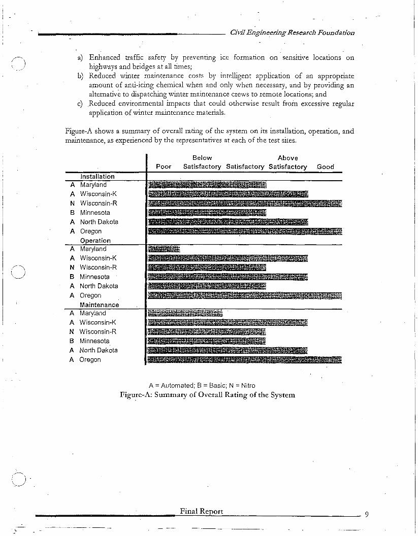
a) Enhanced traffic safety by preventing Ice formation on sensitive locations onhighways and bridges at all times;
b) Reduced winter maintenance costs by intelligent application of an appropr!ateamount of anti-icing chemical when and only when necessary, and by providing analternative to dispatching winter maintenance crews to remote locations; and
c) _Reduced environmental impacts that could otherwise result from excessive regularapplication of winter maintenance materials.
Figure-A shows a summary of overall rating of the system on its installation, operation, andmaintenance, as experienced by the representatives at each of the test sites.
PoorBelow Above
Satisfactory Satisfactory Satisfactory Good
InstallationA Maryland
A Wisconsin-K
N Wisconsin-R
B MinnesotaA North Dakota
A Oregon
OperationA Maryland
A Wisconsin-K
0 N Wisconsin-R
B Minnesota
A North Dakota
A Oregon
MaintenanceA Maryland
A Wisconsin-K
N Wisconsin-R
B Minnesota
A North Dakota
A Oregon
o
~.' , ' .
A =Automated; B =Basic; N =Nitro
Figu!e-A: Summary of Overall Rating of the System
Final Report 9
_. \, -----.------.

o
o
Civil Engineering Research Foundation
Chapter 1: Introduction-
1.1 Background
As part of its Highway Innovative Technology Evaluation Center (HITEC) program, CERFhas undertaken the evaluation of the FreezeFree system, an anti-icing spray technology thatis a product of the Chicago-based Energy Absorption Systems, Inc. The FreezeFreetechnology consists of an anti-icing system designed for application on bridges, curves,ramps, steep grades and high incident locations. The system features an anti-icing systemthat provides measured applications of anti-icing liquids on targeted areas at appropriatetimes. The study was initiated after the Federal Highway Administration (FHWA) received adirective from the U.S. Congress to evaluate the effectiveness of FreezeFree technology.
As part of an earlier phase of this project, CERF had developed guidelines2 for evaluatingthe system, and had facilitated the selection of sites for installation of the system on seven(7) test locations in six (6) different states including California, Maryland, Minnesota, NorthDakota, Oregon, and Wisconsin. This report is the product of the final phase of this project;and provides a comprehensive documentation of the test sites, the types of systems installed,and the installation, operation, and maintenance of those systems as experienced by thepersonnel responsible for managing those systems at each of the test sites.
The evaluation was directed by the technical evaluation panel assembled by HITEC todevelop the FreezeFree evaluation plan1 as part of an earlier effort. The evaluation panelincludes industry experts, representatives of FHWA, and representatives of statetransportation agencies responsible for the test sites.
In summary, the goal of this effort was to conduct an objective, consensus-based assessmentof the perfonnance of a system that has potential for improving highway safety and mobility,and reducing winter maintenance costs.
1.2 Anti-Icing of Bridge Decks and Other Problem Locations
1.2.1 The ProblemIn any highway maintenance operation, some sites on the system have characteristics thatpose a particular challenge to the field forces charged with carrying out the work and requirea disproportionate amount of attention and expenditure of resources.
In the particular case of winter maintenance, bridge decks are one such class of problemlocations. Because of tlle difference in the thermal regime of bridges and pavements, bridgedecks usually freeze sooner than the adjoining pavement. At stream crossings, this problemcan be further aggravated by generally higher levels of available moisture (humidity) ncar the
21-lighway Innovative Technology Evaluation Center, "HITEC Evaluation Plan for Energy AbsorptionSystem, Inc. FreezeFree System", March 28, 2002.
Final Report 10
o
o
o
Civil1!ngineering Research Foundation
bridge. This moisture can condense on the deck and freeze, even wh.ile the nearby pavementremains frost or ice-free (so-called "preferential icing"). As a result, bridge decks commonlyrequire anti-icing treatment earlie~ and more ofte~ than pavement.
Providing timely and effective anti-icing operations on bridge decks thus causes the normaloperational problems of (a) detecting the need for an anti-icing operation and (b) applyingthe appropriate strategy to be more acute and costly by, e.g., requiring more frequentemergency or off-hours call-outs of patrol trucks.
A second class of problematic winter maintenance locations are high crash sites: placeswhere sharp curves, steep grades, poor sight distance, a particularly harsh microclimate, orother undesirable conditions contribute to a disproportionate number or rate of crashesduring snow and ice events.
Finally, a third situation where providing a prescribed level of service can be particularlycostly and inefficient is in servicing critical sites that are difficult to reach due to theirdistance from the winter maintenance yard or due to traffic congestion. These critical sites- usually, bridge decks or high crash locations - pose the same operational problemsdescribed above, but to a more pronounced degree, due to the influence of increased timeand/or distance from the maintenance workshop.
Clearly, the operational difficulties associated with providing effective anti-icing at problemlocations have significant economic implications not only in terms of direct agency costs, butalso in terms of crash costs. When the very substantial benefits accruing from providingimproved motorist safety during winter storms is factored in, significant capital investmentsin improved technology may - in appropriate cases - be warranted. Indeed, the potentialpayoff of early intervention in snow removal and ice control in terms of improved qualityof-service (motorist convenience, mobility, and safety) was a major factor in the decision bytransportation agencies in recent years to make substantial investments in advancedtechnology to permit anti-icing to be more systematically and effectively applied. Thoseinvestments in advanced technology-collectively referred to as tlle "new generation of Snowand ice control,,3 and "a revolution in winter maintenance,,4 - include specially equippedapplicator trucks, sophisticated management information systems, and innovative ice controlmaterials.
.1.2.2 FAST-The Proposed SolutionStudies in the US5 and CanadaG indicate that a technology first used in Europe - genericallyreferred to as Fixed Anti-icing Spray Technology (FAST) - can be a cost-effective meansfor improving motorist safety on bridge decks during winter storms. Unlike tlle traditional
3 "Tbe Neill Gemration ojSnol/l and he ControL' Anli-icing and RlI7JS," a brochure developed by the Iowa DOT aspart of the AASHTO Lead States Program (1998).
4 Chollar, B. "A Revolution in Winter Maintenance," Public Roads On-Line, FH\\lA (\~\/inter 1996).5 Decker, R., "Automated Bridge Deck l\nti- and Deicing System," NCHRP-IDEA Project 27 Report(November 1998).GPinet, M. et aI, "Anti-Icing on Structures Using Fixed A"Utomated Spray Technology (FAST)," presented atthe 2001 i\nnual Conference of the Transportation Association of Canada, Halifax, Nova Scotia (J'vfay 1,2001).
Final Report 11
(J
o·
Civil Engineering Research Foundadon
mobile (truck-mounted) equipment for applying anti-icing chemicals, the mechanical sprayerin a FAST system is permanently installed on the site.
The FreezeFree.™ system. is a proprietary FAST system. First installed in Wisconsin inJanuary 2000, it consists of two major subsystems: a control system and a hydraulic system.The control system consists of sensors that detect tlle need for an application of anti-icingchemical, and a remote processing unit (RPU), which collects and stores the sensor data andactivates and deactivates tlle spray cycle. The hydraulic system consists of a storage tank andpump that dispenses ilie anti-icing fluids ilirough a series of solenoid-controlled nozzlesalong a lengili of steel piping. The nozzles may be side-mounted on a parapet or guardrail,or flush-mounted in ilie pavement or bridge deck.
The sensors used in ilie FreezeFree control system are available in a range of options, iliechoice of which will affect tlle accuracy of ilie detection, ilie flexibility and reliability of theoverall operation, as well as ilie system cost. For example, detection may be based solely ondata from a pavement sensor (i.e., surface temperature, surface condition, brine freezingpoint) or upon ilie full panoply of pavement and atmospheric data from an on-siteEnvironmental Sensor Station (i.e., wind speed, air temperature, humidity, etc.) as part of aRoad Weather Information System (RWIS). Furilier, pavement sensors are available as eiilieractive or passive units. A passive sensor estimates the freezing point of any brine present onthe pavement surface from measurements of conductivity; an active sensor measuresfreezing point directly by freezing a sample of the liquid.
A range of options is also available for activating ilie FreezeFree system. The spray cycle canbe manually activated - eitller on-site or remotely by telephone - or ilie system can beoperated fully automatically, based on tlle programmable logic incorporated in a proprietaryFreezeFree computer algoritllm. (Among otller tl1ings, ilie choice between manual and fullyautomatic activation may be influenced by tlle relative sophistication of ilie detection systemselected by ilie user.)
The FreezeFree system is designed to be used as a "fIrst response," anti-icing system, not asa snow removal tool. For some winter events (e.g., tlle classic early morning transientfrosting of a bridge deck), timely applications by ilie FreezeFree system may be tlle onlyaction necessary to effectively deal with tlle incident. Prolonged heavy snowfalls will stillrequire plowing. In such cases, tlle FreezeFree system ideally will cycle only long enough toperform its basic anti-icing function - i.e., supplying enough freezing point depressant toprevent a tight ice/pavement bond from forming or developing - and tllen deactivate untilany accumulated snow is removed. Depending on tlle sophistication of tlle installeddetection equipment, such deactivation may requiJ.·e intervention by maintenance staff.
1.2.3 Potential Benefits of FAST
Including FAST as part of the winter operations infrastructure can result in numerousbenefIts. These benefits, depending on the type of system and tlle ability of tlle system toperform as designed, include:
Final Report 12
n ••"---._-"-
••
•
•
•
••
•
•
()
o
1'0.
Civil Engineering-Research Foundation
Proactive approach to snow and ice control;
Automated control over timeliness of activa,tion, resulting in the application ofch~mical-onlywhen it is most effective; ,
Potential for'reduction in winter weather-related-crashes at high-crash locations;
Reduced/minimal staffIng needs, resulting in a direct impact on reducing operatingcosts;
Ability to apply chemical at any time of the day, every day of the year, regardless ofholidays, public closings, and staff availability;
Ability to instantly apply chemical on sites at remote locations with distant anddiffIcult access to winter maintenance vehicles, especially in bad weather conditions;
EffIcient use of the chemical due to need-based application, resulting in economicbenefIts and reduced environmental impact;
Flexibility in setting and modifying spray logic based on site conditions;
Flexibility in using alternative chemicfls at tlle site, including chemicals tlnt are lesscorrosive to structures;
Ability to accurately monitor the amount of chemical being used per mile perstructure; andGeneration and collection of extensive data that can be used to develop models onspray requirements.
1.3 Organization of the Report
This report is organized in seven (7) different chapters. Following the fIrst chapter thatintroduces the evaluation, Chapter 2 provides an overview of the different types ofFreezeFree systems, and the various components that are part of each of these systems.Chapter 3 provides a description of the seven (7) test sites located in six (6) different statesfrom the East Coast to the West Coast. Chapter 4 provides a description of the experienceof tlle State DOT personnel with tlle installation of the system at tlle test sites. Chapter 5describes tlle Operation and Maintenance of tlle system, while Chapter 6 provides a briefsummary of the fIndings from tlle analysis of data collected at the test sites. Chapter-7presents the key highlights of the fIndings and conclusions from the system evaluationprocess.
Final Report
..._--_._..._----~-------
13
(~\J
Civil Engineering Research Foundation·
Chapter 2: System Information
This chapter <liscusses. the generic version of the FreezeFree Anti-Icing System as it is. typically presented in Product and Installation Manuals. The actual system deployed at eachsite is specifically designed to meet the needs and requirements at the site, and may varyfro·m site to site as seen in the following chapters. The FreezeFree System is designed andmanufactured by Energy Absorption Systems, Inc., of Chicago, Illinois. It is available inthree different types:
• FreezeFree™ Basic
• FreezeFree™ Automated
• FreezeFree™ Nitro
2.1 FreezeFree™ Basic?
The FreezeFree Basic is a fIxed anti-icing system that provides treatment of a bridge, ramp,or other problem location. The FreezeFree Basic dispenses a liquid anti-icing agent bypumping the chemical through a series of high-pressure spray nozzles, individuallycontrolled by solenoid valves. Upon activation, the system energizes a motorized pump andautomatically sequences the solenoid valves to spray the anti-icing liquid over the targetedarea.
A programmable controller activates the motorized pump to bring the system to itsoperating pressure. An anti-icing chemical is circulated by the pump through anoverpressure relief valve back to the storage tank to provide agitation of the solution. Aseries of solenoid valves is then sequentially opened and closed to purge air from the systemand dispense the anti-icing chemical. The anti-icing cycle can be initiated remotely via ameans of communication medium such as telephone, cell phone, pager, computer, etc., or bymanually pushing a button at the controller assembly.
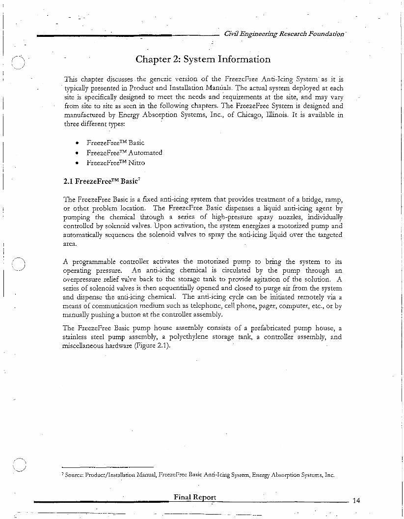
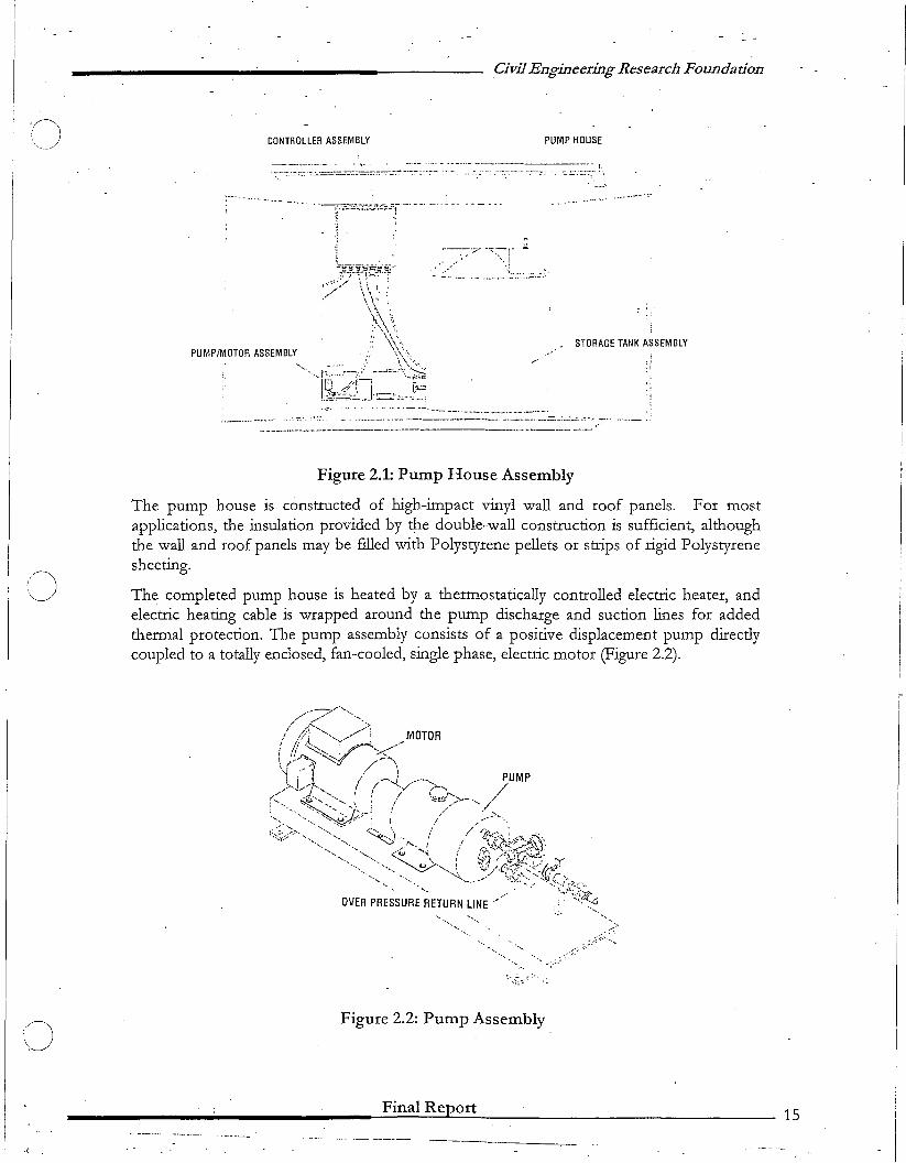
The FreezeFree Basic pump house assembly consists of a prefabricated pump house, astainless steel pump assembly, a polyethylene storage tank, a controller assembly, andmiscellaneous hardware (Figure 2.1).
7 Source: Product/Installation Manual, FrcezeFree Basic Anti-Icing System, Energy Absorption Systems, Inc.
Final Report 14
---,--~----- -----------
CONTROLLER ASSEMBLY
CivilEngineering Research Foundation
PUMP HOUSE
•.••.~.-- '<:"
:~'''''"'::::-r._. _....._ '·L :......;:.__::.
STORAGE TANK ASSEMBLY
.;
---..-....._-_.__.__.:::..:"'",,-,- .. _..
()
.1,
Figure 2.1: Pump House Assembly
The pump house is constructed of high-impact vinyl wall and roof panels. For mostapplications, the insulation provided by the double-wall construction is sufficient, althoughthe wall and roof panels may be filled with Polystyrene pellets or strips of rigid Polystyrenesheeting.
The completed pump house is heated by a thermostatically controlled electric heater, andelectric heating cable is wrapped around the pump discharge and suction lines for addedthermal protection. The pump assembly consists of a positive displacement pump directlycoupled to a totally enclosed, fan-cooled, single phase, electric motor (Figure 2.2).
'-'
Figure 2.2: Pump Assembly
Final Report
--------._----15
o
o
Cilil Engineering Research Foundation
A variable pressure relief-valve is· attached to the pump discharge, with an over pressurereturn line connected to the storage tank. The pump and relief valve are constructed ofstainless steel, and the internal valve c'omponents are made of chromium alloys. The storagetank is molded polyethylene. Standard tank sizes typically range from 375 to 700 gallons.Other sizes are provided depending on the specific needs at the' site. The tank assemblyconsists of the tank with a yented lid, two level switches, and PVC fittings for the suctionline, return line, and drain.
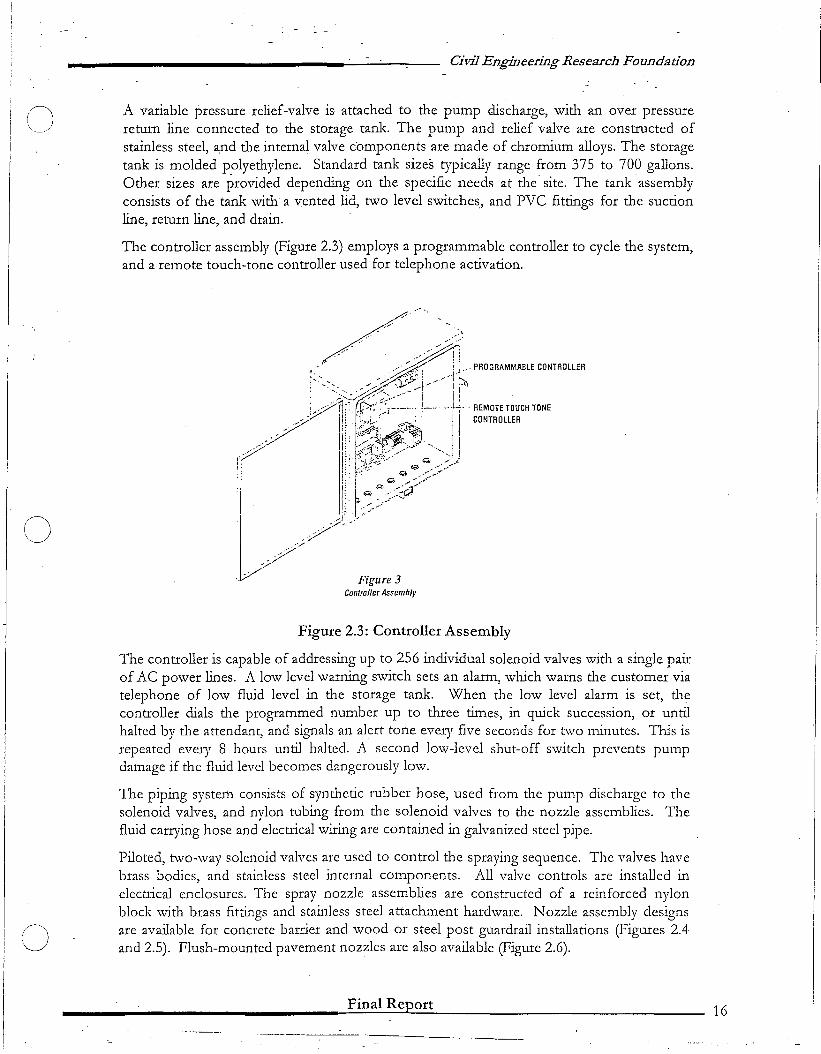
The controller assembly (Figure 2.3) employs a programmable controller to cycle the system,and a remote touch-tone controller used for telephone activation.
Figure 2.3: Controller Assembly
The controller is capable of addressing up to 256 individual solenoid valves with a single pairof AC power lines. A low level warning switch sets an alarm, which warns the customer viatelephone of low fluid level in the storage tank. When the low level alarm is set, thecontroller dials the programmed number up to three times, in quick succession, or untilhalted by the attendant, and signals an alert tone every five seconds for two minutes. This isrepeated every 8 hours until halted. A second low-level shut-off switch prevents pumpdamage if the fluid level becomes dangerously low.
The piping systerh consists of synthetic rubber hose, used from the pump discharge to thesolenoid valves, and nylon tubing from the solenoid valves to the nozzle assemblies. Thefluid carrying hose and electrical wiring are contained in galvanized steel pipe.
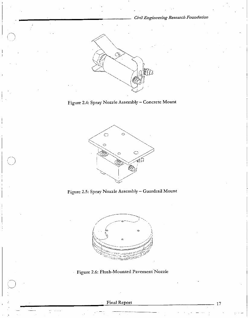
Piloted, two-way solenoid valves are used to control the spraying sequence. The valves havebrass bodies, and stainless steel internal components. All valve controls are installed inelectrical enclosures. The spray nozzle assemblies are constructed of a reinforced nylonblock with brass fittings and stainless steel attachment hardware. Nozzle assembly designsare available for concrete barrier and wood or steel post guardrail installations (Figures 2.4and 2.5). Flush-mounted pavement nozzles are also available (Figure 2.6).
Final Report
.._--... __._----------16
__ .--~' ;,0.--·-···. _, ._......J'
o
(J
Cild] Engineering Research Foundadon
Figure 2.4: Spray Nozzle Assembly - Concrete Mount
Figure 2.5: Spray Nozzle Assembly - Guardrail Mount
~,~,--"-"-----"---.................- .~.
"f//"
Figure 2.6: Flush-Mounted Pavement"Nozzle
Final Report 17
C)
C)
()
Civil EngiDeering Rese~rchFoundation
82.2 FreezeFree™ Automated
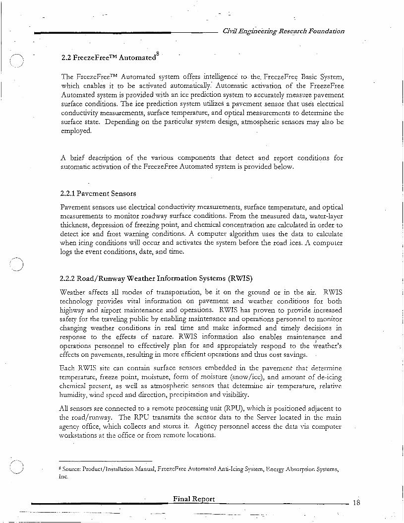
The FreezeFree™ Automated system offers intelligence to the. FreezeFree Basic System,which enables it to be activated automatically.· Automatic activation of the FreezeFreeAutomated system is provided with an ice prediction system to accurately measure pavementsurface conditions. The ice prediction system utilizes a pavement sensor that uses electricalconductivity measurements, surface temperature, and optical measurements to determine thesurface state. Depending on the particular system design, atmospheric sensors may also beemployed.
A brief description of the various components that detect and report conditions forautomatic activation of the FreezeFree Automated system is provided below.
2.2.1 Pavement Sensors
Pavement sensors use electrical conductivity measurements, surface temperature, and opticalmeasurements to monitor roadway surface conditions. From the measured data, water-layerthickness, depression of freezing point, and chemical concentration are calculated in order todetect ice and frost warning conditions. A computer algorithm uses the data to calculatewhen icing conditions will occur and activates the system before the road ices. A computerlogs the event conditions, date, and time.
2.2.2 Road/Runway Weather Information Systems (RWIS)
Weather affects all modes of transportation, be it on the ground or in the air. RWIStechnology provides vital information on pavement and weather conditions for bothhighway and airport maintenance and operations. RWIS has proven to provide increasedsafety for the traveling public by enabling maintenance and operations personnel to monitorchanging weather conditions in real time and make informed and timely decisions inresponse to the effects of nature. RWIS information also enables maintenance andoperations personnel to effectively plan for and appropriately respond to the \~eather'seffects on pavements, resulting in more efficient operations and thus cost savings.
Each RWIS site can contain surface sensors embedded in the pavement that determinetemperature, freeze point, moisture, form of moisture (snow/ice), and amount of de-icingchemical present, as well as atmospheric sensors that determine air temperature, relativehumidity, wind speed and direction, precipitation and visibility.
All sensors are connected to a remote processing unit (RPU), which is positioned adjacent tothe road/runway. The RPU transmits the sensor data to the Server located in the mainagency office, which collects and stores it. Agency personnel access the data via computerworkstations at the office or from remote locations.
H Source: Product/In~tallation Manual, FreezeFree Automated Anti-Icing Sys"tem, Energy Absorption Systems,Inc.
Final Report
--_._--~-_. _. ...
18
o
o
C]
" ...,
Civil Engineering Research Foundadon
An integral component of RWIS is pavement-specific weather forecasting. While the RWISsensors provide. timely information on current and historical conditions, it is the pavementspecific weather forecasts that serve as the predictor of the future. K.nm:ving what type of
- weather will occur is key to being and' staying one step ahead of the storm. Accuratepavement-sp~cificweather forecasts are a necessity for any efficient and effective anti-icingprogram.
2.2.3 ScanWeb
ScanWeb is the latest Road/Runway Weather Information Systems (RWI5) user interfacefrom Surface System's, Inc. (5S1). ScanWeb uses standard Internet technologies to displaydata from the RWI5. These technologies include the Transmission ControlProtocol/Internet Protocol (TCP/IP), the Hypertext Transfer Protocol (HTTP), theHypertext Markup Language (HTML), and Active Server Pages (ASPs). These standardsform the foundation of what has become commonly known as the World Wide Web(WWW). ScanWeb makes use of these standards technologies to display SCAN RWIS datausing widely available HTML browsers such as Netscape Navigator and Microsoft InternetExplorer.
ScanWeb provides powerful graphical data display pages. Users can easily select various dataviews to display and produce either concise summary views or detailed RWIS data. SiteSummary, Site Status, and historical data pages are available to enhance operationaleffectiv:eness. In addition, ScanWeb integrates current video images when sites areconfigured with video cameras.
2.3 FreezeFree™ Nitro9
The FreezeFree™ Nitro Anti-Icing System is a variation of the FreezeFree B~sic system. Itis a solar-charged, battery-powered system in which a pressurized nitrogen tank propels antiicing fluid sprayed on a bridge, ramp or other problem location, without the need forexternal electrical power or telephone communication lines. Upon actuation, anti-icingchemical is gravity fed on demand to a pressure vessel, which is then pressurized withgaseous nitrogen, regulated to maintain the design operating pressure throughout theSystem. A progranunable logic controller (pLC) monitors and controls System fluid levelsand pressure, and energizes a sequence of solenoid valves to dispense the anti-icing liquidover the targeted area.
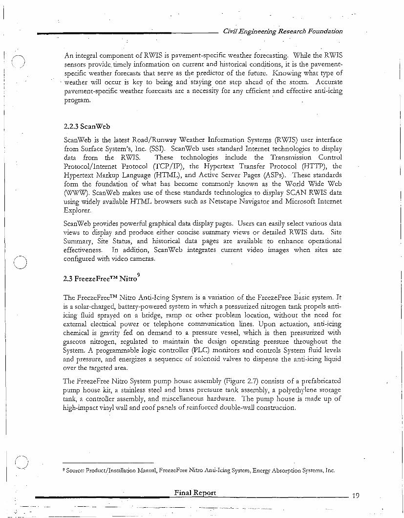
The FreezeFree Nitro System pump house assembly (Figure 2.7) consists of a prefabricatedpump house kit, a stainless steel and brass pressure tank assembly, a polyethylene storagetank, a controller assembly, and miscellaneous hardware. The pump house is made up ofhigh-in1pact vinyl wall and roof panels of reinforced double-wall construction.
9 Source: Product/Installation 1\.fanual, FreezeFree Nitro Anti-Icing System, Energy Absorption Systems, Inc.
Final Report 19
o
Civil Engineering Research Foundation
SOLAR CHARGING SYSTEM
CONTROLLER ASSEMBLY
REGULATORASSEMBLY------J+--t"t:l~
PUMP HOUSESTORAGE TANK ASSEMBLY
PRESSURE TANKf-.'""--_--'==='___-"I
ASS"LY
.. '.
o
()
Figure 2.7: Pump House (Nitro)
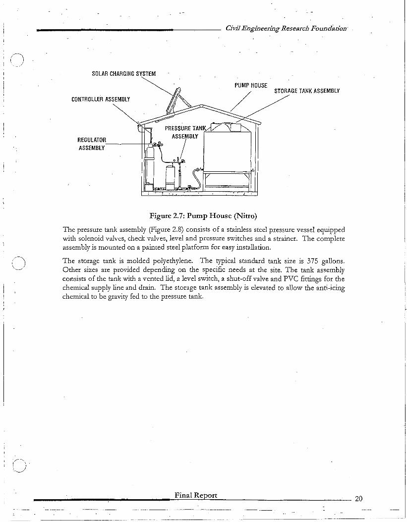
The pressure tank assembly (Figure 2.8) consists of a stainless steel pressure vessel equippedwith solenoid valves, check valves, level and pressure switches and a strainer. The completeassembly is mounted on a painted steel platform for easy installation.
The storage tank is molded polyethylene. The typical standard tank size is 375 gallons.Other sizes are provided depending on the specific needs at the site. The tank assemblyconsists of the tank with a vented lid, a level switch, a shut-off valve and PVC fittings for thechemical supply line and drain. The storage tank assembly is elevated to allow the anti-icingchemical to be gravity fed to the pressure tank.
________~-------~F~in~a:.:...l....:.R....:.e.::;Jp[:....o;:.:r:..:t---------------_20
--- .. ---_._-_._------_.-
(J
PRESSURE TANK
PRESSURE SWITCH,
Civil Engineering Research Foundation
/OLENOID VAlVE
lEVEL SWITCH
SUPPLY VALVE
;-SP-RAYi ~fOR-AG~
~V!-~V_E§J ~~~~~~9~~~~X:=:~~*~~~~1..b=!tl;"L..-''l-Q-J<'''''--~}~~~~
PLATFORM
Figure 2.8: Pressure Tank (Nitro)
The controller assembly employs a programmable logic controller (pLC) to cycle the System,and a remote control paging device for r.emote activation.
___--------------=-F..:.:in=a=I~R:..:;e.::Jpl:-o.::..:r:..:t~--------------_21
o
o
o
Civil Engineering Research Foundadon
Chapter 3: Test Sites
In order to conduct an ~valuation of the FreezeFree ~ystem, seven (7) "test sites were select~dnationwide in six different states, including Maryland, Wisconsin, Minnesota, North Dakota,Oregon, and California. Five of these sites consist of system installation on bridges, whilethe other two consist of system installation on sloping, curved pavements.
The FreezeFree systems installed on various sites were for the most part, unique. Thisuniqueness existed in terms of the type of system such as Basic, Automated, or Nitro, typeof sensor (active or passive), types of nozzles, and so forth. This variety of system features,on the one hand, was useful in representing the various features and possible configurationsof the system, but on the other hand, made it difficult to compare system performance fromone site to another. In addition, repairs and upgrades of the system on an ongoing basismade it difficult to "lock" the various parameters within a system for the purpose ofmonitoring performance over time at any given site.
The following sections discuss each of the test sites, and the type of system installed onthose sites:
3.1 Maryland
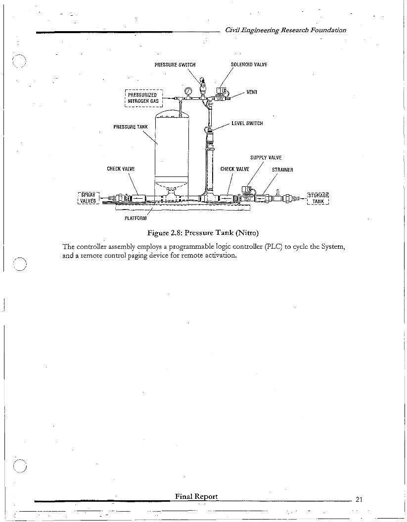
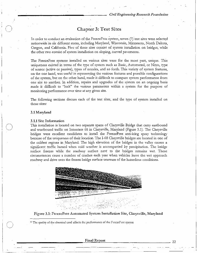
3.1.1 Site InfonnationThis installation is located on two separate spans of Clarysville Bridge that carry eastboundand westbound traffic on Interstate 68 in Clarysville, Maryland (Figure 3.1). The Clarysvillebridges were excellent candidates to install the FreezeFree anti-icing spray technologybecause of the uniqueness of their location. The 1-68 Clarysville bridges are located in one ofthe coldest regions in Maryland. The high elevation of the bridges in the valley causes asignificant traffic hazard when cold weather is accompanied by precipitation. The bridgesurface freezes while the roadway surface next to the bridges remains wet. Thesecircumstances cause a number of crashes each year when vehicles leave the wet approachroadway and drive onto the frozen bridge surface unaware of the hazardous conditions.
.;~. .
Figure 3.1: FreezeFree Automated System Installation Site, Clarysville, Maryland
13 The quality of the chemical used affects the performance of the FreezeFree sys~em
________________--=.F..:.:in;:.;a;.;.;;I...;,R...;,e;:Jp.:....o:;,.:r:..:t-------- 22
o
0-
Civil Engineering Research Foundation
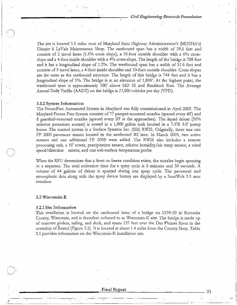
The site is located 3.5 miles west of Maryland State Highway Administration's (MDSFIA's)District 6 LaVale Maintenance Shop. The eastbound span has a width of 39.6 feet andconsists of 2 travel lanes (1.6% cross slope), a 10-foot outside shoulder with a 6% crossslope and a 4-foot inside" shoulder with a 4% cross-slope. The length of the bridge is 708 feetand it has a longitudinal slope of 1.5%. The westbound span has a width of 51.6 feet andconsists of 3 travel lanes, a 4-foot inside shoulder and 10-foot outside shoulder. Cross slopesare the same as the eastbound structure. The length of this bridge is 744 feet and it has alongitudinal slope of 5%. The bridge is at an elevation of 1,800'. At the highest point, thewestbound span is approximately 100' above MD 55 and Braddock Run. The AverageAnnual Daily Traffic (AADT) on the bridge is 27,000 vehicles per day (VPD).
3.1.2 System InformationThe FreezeFree Automated System in Maryland was fully comn;J.issioned in April 2002. TheMaryland Freeze Free System consists of 77 parapet-mounted nozzles (spaced every 40') and8 guardrail-mounted nozzles (spaced every 20' at the approaches). The liquid deicer (50%solution potassium acetate) is stored in a 1,000 gallon tank located in a 7.5'X 9.0' pumphouse. The control system is a Surface Systems Inc. (SSI) RWIS. Originally, there was oneFP 2000 pavement sensor located in the eastbound #2 lane. In March 2003, two activesensors and one additional FP 2000 were added. The RWIS also includes a remoteprocessing unit, a 10' tower, precipitation sensor, relative hunJidity/air temp sensor, a windspeed/direction sensor, and one sub-surface temperature probe.
When the RPU detennines that a frost or freeze condition exists, the nozzles begin sprayingin a sequence. The total activation time for a spray cycle is 8 minutes and 30 seconds. Avolume of 44 gallons of deicer is sprayed during one spray cycle. The pavement andatmospheric data along with the spray device history are displayed by a ScanWeb 3.3 userinterface.
3.2 Wisconsin-K
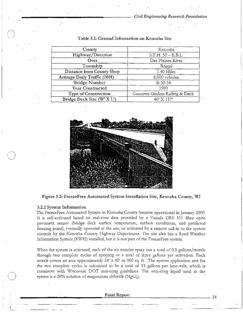
3.2.1 Site InformationTIllS installation is located on the eastbound lanes of a bridge on STH-50 in KenoshaCounty, Wisconsin, and is therefore referred to as Wisconsin-K site. The bridge is made upof concrete girders, railing, and deck, and spans 137 feet over the Des Plaines River in thetownsillp of Bristol (Figure 3.2). It is located at about 1.4 nllles from the County Shop. Table3.1 provides information on the Wisconsin-K installation site.
________________--=.F..:::in=.a=l:....:R:..::..::.ep[:,.o::..:r:..:t- 23
Civil Engineering Research Foundation
Table 3.1: General Information on Kenosha Site
KenoshaS.T.H. 50 - E.B.L.Des Plaines River.
Bristol1.40 Miles
8,900 vchiclesB-30-54
1989Concrete Girders Railin & Deck
40' X 137'
()
o
Figure 3.2: FreezeFree Automated System Installation Site, Kenosha County, WI
3.2.2 System InformationThe FrcczeFree Automatcd Systcm in Kcnosha County becamc operational in January 2000.It is self-activatcd based on rcal-time data provided by a Vaisala DRS 511 fibcr opticpavcment sensor (bridge dcck surface temperature, surface conditions, and predictedfreezing point), manually operated at the site, or activated by a remotc call-in to the systemcontrols by the Kenosha County Highway Department. The site also has a Road WeatherInformation System (RWIS) installed, but it is not part of the FreezeFree system.
When the system is activated, cach of the six nozzles spray out a total of 0.5 gallons/nozzlethrough two complcte cycles of spraying or a total of three gallons per activation. Eachnozzle covers an area approximately 24' x 40' or 960 sq. ft. The system application rate forthe two complete cycles is calculated to be a total of 33 gallons per lane-mile, which isconsistent with Wisconsin DOT anti-icing guidelines. The anti-icing liquid used in thesystem is a 26% solution of magnesium chloride (MgClz).
________________--=-F..:::in:::a:;.:l:..:R:.::.::Jept.:..o::;r:.;;t-- -- 24
._--_...._-------_._-- ._---
()-'~
Civil Engineering Research Foundation
3.3 Wisconsin-R
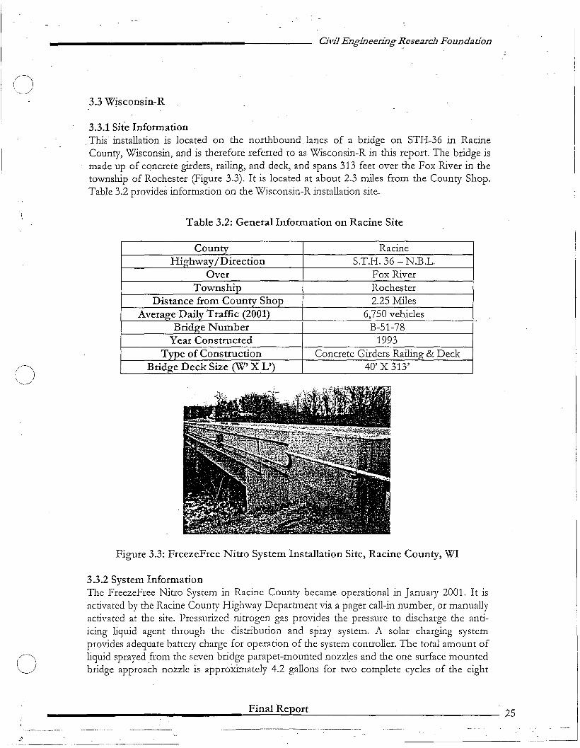
3.3.1 Site InformationThis installation is located on the northbound lanes of a bridge on STH-36 in RacineCounty, Wisconsin, and is therefore referred to as Wisconsin-R in this report. The bridge ismade up of concrete girders, railing, and deck, and spans 313 feet over the Fox River in thetownship of Rochester (Figure 3.3). It is located at about 2.3 miles from the County Shop.Table 3.2 provides information on the Wisconsin-R installation site.
Table 3.2: General Information on Racine Site
()
RacineS.T.H. 36 - N.B.L.
Fox RiverRochester2.25 Miles
6,750 vehiclesB-51-78
1993Concrete Girders Railin & Deck
40' X 313'
(J
Figure 3.3: FreezeFree Nitro System Installation Site, Racine County, WI
3.3.2 System InformationThe FreezeFree Nitro System in Racine County became operational in January 2001. It isactivated by the Racine County Highway Department via a pager call-in number, or manuallyactivated at the site. Pressurized nitrogen gas provides the pressure to discharge the antiicing liquid agent through the distribution and spray system. A solar charging systemprovides adequate battery charge for operation of the system controller. The total amount ofliquid sprayed _from the seven bridge parapet-mounted nozzles and the one surface mountedbridge approach nozzle is approXimately 4.2 gallons for two complete cycles of the eight
________________-=-F.=.::in=a:..:.:I-=R:..::.e:=Jp~o:.:r:..::.t---- 25
o
o
Civil Engineering Research Foundadon
nozzles (0.5 gallon/parapet nozzle/application and 0.7 gallon/surface nozzle/application).The application rate for this system is similar to that of the Kenosha County installation,which is 33 gallons per lane mile. The anti-icing material used in the system is a 26% solutionof magnesium chloride, the same as the liquid agent used at the Kenosha County site.
3.4 Minnesota
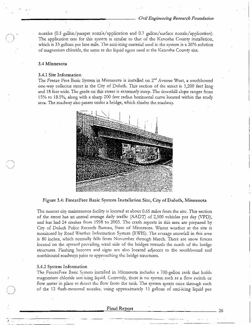
3.4.1 Site InformationThe Freeze Free Basic System in Minnesota is installed on 2nd Avenue West, a southboundone-way collector street in the City of Duluth. This section of the street is 1,200 feet longand 18 feet wide. The grade on this street is extremely steep. The downhill slope ranges from15% to 18.5%, along with a sharp 200 feet radius horizontal curve located within the studyarea. The roadway also passes under a bridge, which shades the roadway.
Figure 3.4: FreezeFree Basic System Installation Site, City of Duluth, Minnesota
The nearest city maintenance facility is located at about 0.65 miles from the site. This sectionof the street has an annual average daily traffic (AADT) of 2,500 vehicles per day (VPD),and has had 24 crashes from 1998 to 2003. The crash reports in this area are prepared byCity of Duluth Police Records Bureau, State of Minnesota. Winter weather at the site ismonitored by Road Weather Information System (RWIS). The average snowfall in this areais 80 inches, which normally falls from November through March. There are snow fenceslocated on the upward prevailing wind side of the bridges towards the north of the bridgestructures. Flashing beacons and signs are also located adjacent to the southbound andnorthbound roadways prior to approaching the bridge structures.
3.4.2 System InformationThe FreezeFree Basic System installed in Minnesota includes a 700-gallon tank that holdsmagnesium chloride anti-icing liquid. Currently, tl1ere is no system such as a flow switch orflow meter in place to detect tl1e flow from the tank. The system sprays once tl1tough eachof-the 12 flush-mounted nozzles, using approximately 15 gallons of anti-icing liquid per
________________--=.F..::in=a=I:...:R:..::..::.ept:..o.::.:r:.:t~- _.:.... _'____ 26
---.. _----_._--,---------/~ --
o
Civil Engineering Research Faun-dation
activation. -
The Duluth system ca~ be manually activated at the site _or by telephone. There are nopavement sensors or other means of kilowing what the pavement conditions are prior toactivation. The decision on when to fIre the system is based on the judgment of themaintenance foreman. For that reason, it may not function as a true automated anti-icingsystem.
3.5 North Dakota
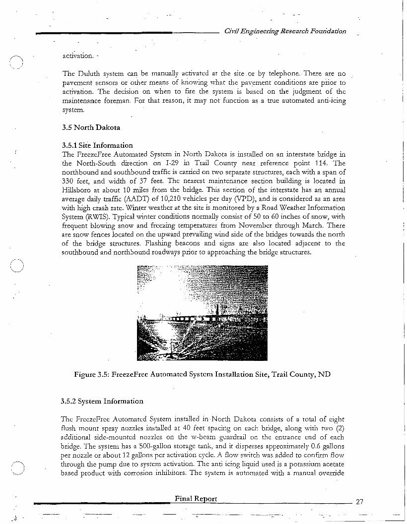
3.5.1 Site InformationThe FreezeFree Automated System in North Dakota is installed on an interstate bridge inthe North-South direction on 1-29 in Trail County near reference point 114. Thenorthbound and southbound traffIc is carried on two separate structures, each with a span of330 feet, and width of 37 feet. The nearest maintenance section building is located inHillsboro at about 10 miles from the bridge. This section of the interstate has an annualaverage daily traffIc (AADT) of 10,210 vehicles per day (VPD), and is considered as an areawith high crash rate. Winter weather at the site is monitored by a Road Weather InformationSystem (RWIS). Typical winter conditions normally consist of 50 to 60 inches of snow, withfrequent blowing snow and freezing temperatures from November through March. Thereare snow fences located on the upward prevailing wind side of the bridges towards the northof the bridge structures. Flashing beacons and signs are also located adjacent to thesouthbound and northbound roadways prior to approaching the bridge structures.
Figure 3.5: FreezeFree Automated System Installation Site, Trail County, ND
3.5.2 System Information
The FreezeFree Automated System installed in North Dakota consists of a total of eightflush mount spray nozzles installed at 40 feet spacing on each bridge, along with two (2)additional side-mounted nozzles on the w-beam guardrail on the entrance end of eachbridge. The system has a SOO-gallon storage tank, and it disperses approximately 0.6 gallonsper nozzle or about 12 gallons per activation cycle. A flow switch was added to confum flowthrough the pump due to system activation. The anti-icing liquid used is a potassium acetatebased product with corrosion inhibitors. The system is automated with a manual override
________________......;,...F.;,..in-a-I-R-e~p~o:...:r:..:.t---- 27
Civil Engineering Research Foundadon
capability by phone; cell phone, computer, or manual switch in the pump house. Themonitoring software initially used was ScanWeb 3.1, which was later upgraded to ScanWeb3.3. An FP-2000 passive sensor was installed to provide the automatic sensing for thesyst~m.
3.6 Oregon
3.6.1 Site InformationThe project site is located on US Highway 26 in the Cascade Range Mountains. Thishighway is designated as a Statewide Highway, which runs from the Pacific Ocean throughthe Coast Range Mountains east to the center of the state. The site is approximately 25miles inland from the Pacific Ocean, with an elevation of 1,147 feet, and 24 miles from theManning Maintenance station.
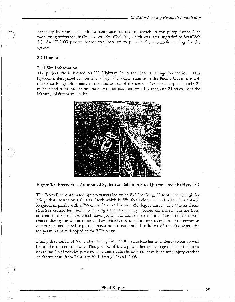
Figure 3.6: FreezeFree Automated System Installation Site, Quartz Creek Bridge, OR
The FreezeFree Automated System is installed on an 835 foot long, 26 foot wide steel girderbridge that crosses over Quartz Creek which is fifty feet below. The structure has a 4.4%longitudinal profile with a 7% cross ·slope and is on a 2V2 degree curve. The Quartz Creekstructure crosses between two tall ridges that are heavily wooded combined with the treesadjacent to the structure, which have grown well above the structure. The structure is wellshaded during the winter months. The presence of moisture or precipitation is a commonoccurrence, and it will typically freeze in the early and late hours of the day when thetemperatures have dropped to the 32"F range.
During the months of November thl'Ough March tllls structure has a tendency to ice up wellbefore tlle adjacent roadway. This portion of tlle lllghway has an average daily traffic countof around 6,800 vehicles per day. The crash data shows there have been nine injury crasheson tlle structure from Fe1?ruary 2001 through March 2003.
Final Report 28
CJ
Civil Engineering Research Foundation
3.6.2 System InformationThe FreezeFree System installed at tlus location consists of twenty-five side spray nozzlesand valve boxes, spaced on forty foot centers,_ and an in-ground concrete vault -for theelectronic components. Magnesium chloride is tlle selected anti-icing material to be_ usedand is stored in a 750-gallon tank within the concrete vault.
This system is self-activated and is interconnected with an existing RWIS system and alsoutilizes the pre-existing in-deck sensors for acti'\ration. When the system is activated, each ofthe twenty-five nozzles will apply 0.5 gallons/nozzle or 12.5 gallons of a 30% solution ofmagnesium chloride through two complete cycles. This is equivalent to a rate of 33 gallonsper lane-mile.
3.7 California
3.7.1 Site InformationThe installation site is located on State Route 2 in the East-West segment outside of LosAngeles, California. The length of the test section is 1,200 feet, with a width of 24 feet fortravel. The nearest maintenance station is located at about 15 miles from the test site. Thissection of tlle highway has an annual average daily traffic (AADT) of 1,300 vehicles per day(VPD). The California Highway Patrol (CHP) is the agency responsible for processingcollision reports for tlUs location.
Figure 3.7: FreezeFree Automated System Installation Site, Los Angeles, CA
3.7.2 System InformationThe installation of the system began in August 2003. The cdnstructionhas not yet beencompleted. The primary reason for tlus delay in installation is related to getting tlle necessary
________________-F-in-a-l-R-ePL..-or-t-- ~---_ 29
------_..__ .. - ..._-----_. ---_._-, ._. --
n'-~~/
(J
()
.'
-':l•••I"
Civil Engi.r::eering Research Foundadon
permits for utilities (electrical power and telephone service) to serve the installation. Also,since the site falls within Angeles National Forest, a construction permit was required fromthe U.S. Forest Service.
The system under installation in California consists of 13 side-mounted nozzles on guardrail,spaced 37.5 feet apart, and 18 flush-mounted nozzles spaced 40 feet apart. A pavementsensor is installed at approximately 50 feet from the pumping station. The system includes a400-gallon storage tank that holds Cryotech CF7, a potassium acetate-based anti-icing liquid.The software that will be used for collecting and viewing the data is ScanWeb.
It is important to note that since the installation ofthe !)!stem at the site in California was not complete at thetime ofpreparation of this report, data and observationsfrom that site could not be included as part of thisevaluation.
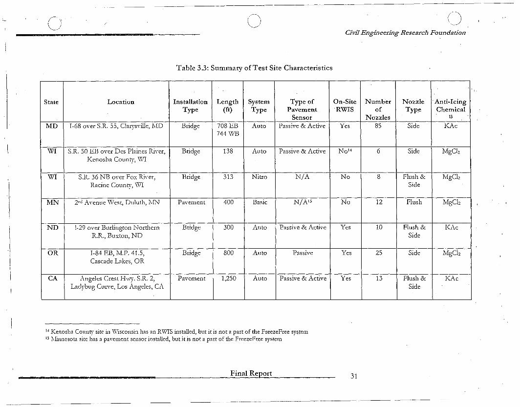
3.8 Summary of Test Site Characteristics
Table 3.3 summarizes the characteristics of each of the test sites and installations.
________________--=-F.:;:in=.:a,;.;.,I...:..R...:..e::.lp::..o:.,:r:.:,t- -::--:--_ _ 30
._-_ ....._--~'---------_... , ..,.,--.....
0' ( o
Table 3.3: Summary afTest Site Characteristics
/\\J
Civil Engineering Research Foundation
'Ii
State Location Installation Length System Type of On-Site Number Nozzle 'Anti-IcingType (ft) Type Pavement .RWIS of Type Chemical
Sensor Nozzles 13
MD 1-68 over S.R. 55, Clarysville, l\:ID Bridge 708 EB Auto Passive & Active Yes 85 Side KAc744 \\1B
WI S.R. 50 EB over Des Plaines Ri,-er, Bridge 138 Auto Passive & Active N 0 14 6 Side MgChKenosha County, \VI
WI S.R. 36 NB over Fox Ri,-er, Bridge 313 Nitro N/A No 8 Flush & MgChRacine County, \'\11 Side
MN 2nd Avenue \\les t, Duluth, l\.[N Pavement 400 Basic N/N5 No 12 Flush MgCh
ND !-29 over Burlington Northern Bridge 300 Auto Passive & Active Yes 10 Flush & KAcR.R., Buxton, ND Side
OR 1-84 EB, M.P. 41.5, Bridge 800 Auto Passive Yes 25 Side MgClzCascade Lakes, OR
CA Angeles Crest Hwy. S.R. 2, Pavement 1,250 Auto Passive & Active Yes 13 Flush & K.f\cLadybug Curve, Los Angeles, CA Side
14 Kenosha County site in \Visconsin has an R\'\11S installed, but it is 110t a part of the FreezeFree sy~tem
15 J\Iinnesota site has a pavement sensor installed, but it is not a part of the FreezeFree system '
Final Report 31
Civil Engineering Research Foundatj0n
Chapter 4: Installation·
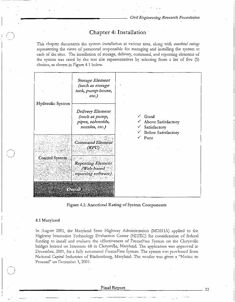
This chapter documents the system installation at various sites, along with anecdotal ratingsrepresenting the views of personnel responsible for managing and installing the system ateach of the sites. The installation of storage, delivery, command, and reporting clements ofthe system was rated by the test site representatives by selecting from a list of five (5)choices, as shown in Figure 4.1 below.
Storage Element(such as storage
tank, pump-house,. etc.)
Hydraulic System f------------i
(J
Delivery Element(such as pump,
pipes, solenoids,nozzles, etc.)
.. ~: ';" "." :':.~::'.~':":_::~';" ~.' .. -.;:.... -, :.::';~
"CorrJri~nd Ele;;;~'ni'.... PJ.I!U)·:,.~;}:_.~
:i«: ....• ',;..;: 5:"~~" . :: .. ;- .;.. .-.' ..:..
./ Good
./ Above Satisfactory
./ Satisfactory
./ Below Satisfactory
./ Poor
o
Figure 4.1: Anecdotal Rating of System Components
4.1 Maryland
In August 2001, the Maryland State Highway Administration (MDSHA) applied to theHighway Innovative Technology Evaluation Center (HITEC) for consideration of federalfunding to install and evaluate the effectiveness of FreezeFree System on the Clarysvillebridges located on Interstate 68 in Clarysville, Maryland. The application \vas approved inDecember, 2001, for a fully automated FreezeFree System. The system was purchased fromNational Capital Industries of Bladensburg, Maryland. The vendor was given a "Notice toProceed" on December 3, 2001.
Final Report 32
oCivil Engmeering Rese~rchFoundation
The system was installed by H&W Contracting of Raleigh, NC between January 28, 2002and. March 25, 2002. A total of 18 working days were required to install the variouscomponents of the System. The Road Wea.ther Information System (RWIS) was installed byGlobal Specialties of St. Louis, MO on March 21-25, 2002. The RWIS was commissioned bySurface Systems Inc. (SS!) on April 2, 2002 and the spray. system was commissioned byEnergy Absorption on April 17, 2002.
The total cost of the system was approximately $265,000. Details on the system are providedin Section 3.1.2. .
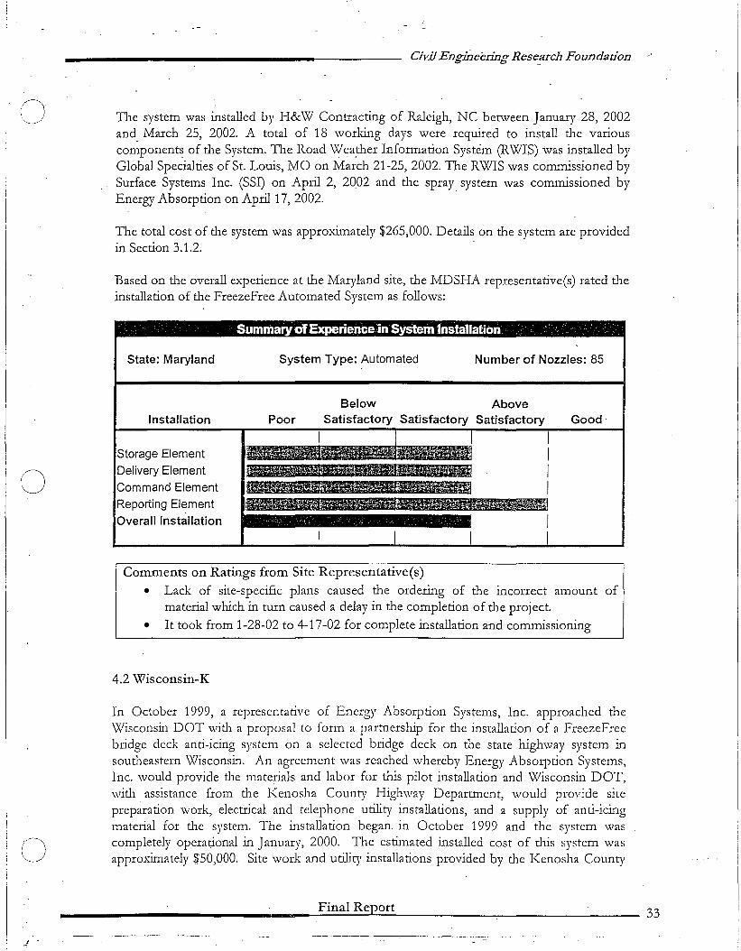
Based on the overall experience at the Maryland site, the MDSHA representative(s) rated theinstallation of the FreezeFree Automated System as follows:
. . SummaryofExperience in System Installation . .
State: Maryland System Type: Automated Number of Nozzles: 85
•
Installation
Storage Element
Delivery Element
Command Element
Reporting Element
Overall Installation
BelowPoor Satisfactory
AboveSatisfactory Good
C)
Comments on Ratings from Site Representative(s)
• Lack of site-specific plans caused the ordering of the incorrect amount ofmaterial which in turn caused a delay in the completion of the project.
• It took from 1-28-02 to 4-17-02 for complete installation and commissioning
4.2 Wisconsin-K
In October 1999, a representative of Energy Absorption Systems, Inc. approached the\Visconsin DOT with a proposal to form a partnership for the installation of a FreezeFreebridge deck anti-icing system on a selected bridge deck on the state highway system insoutheastern Wisconsin. An agreement was reached whereby Energy AbsOlvtion Systems,Inc. would provide the materials and labor for this pilot installation and Wisconsin DOT,with assistance from the Kenosha County Highway Department, would provide sitepreparation work, electrical and telephone utility installations, and a supply of anti-icingmaterial for the system. The installation began in October 1999 and the system wascompletely operational in January, 2000. The estimated installed cost of this system wasapproxin1ately $50,000. Site work and utility installations provided by the Kenosha County
Final Report 33
oCivil Engineering Research Foundation
Highway Department and Wisconsin DOT were estimated to be less than $3,500. Details onthe system are provided in Section 3.2.2.
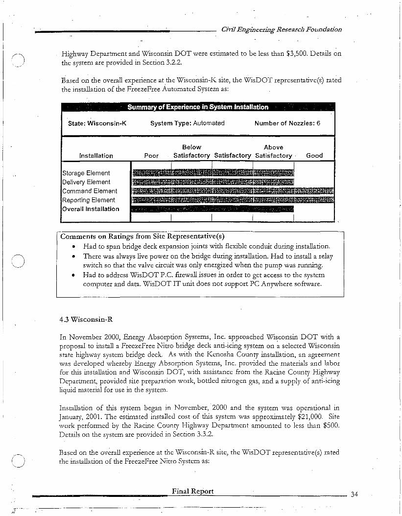
Based on the overall experience atthe Wisconsin-K site, the WisDOT representative(s) ratedthe installation of the FreezeFree Automated System as:
Summary ofExperience in :System Installation
State: Wisconsin-K System Type: Automated Number of Nozzles: 6
Installation
Storage Element
Delivery ElementCommand Element
Reporting ElementOverall Installation
PoorBelow
SatisfactoryAbove
Satisfactory· Good
o
o
Comments on Ratings from Site Representative(s)• Had to span bridge deck expansion joints with flexible conduit during installation.
• There was always live power on the bridge during installation. Had to install a relayswitch so that the valve circuit was only energized when the pump was running.
• Had to address WisDOT P.e. fIrewall issues in order to get access to the systemcomputer and data. WisDOT IT unit does not support PC Anywhere software.
4.3 Wisconsin-R
In November 2000, Energy Absorption Systems, Inc. approached Wi~consin DOT with aproposal to install a FreezeFree Nitro bridge deck anti-icing system on a selected Wisconsinstate highway system bridge deck. As with the Kenosha County installation, an agreementwas developed whereby Energy Absorption Systems, Inc. provided the materials and laborfor tlus installation and Wisconsin DOT, with assistance from the Racine County HighwayDepartment, provided site preparation work, bottled nitrogen gas, and a supply of anti-icingli(lUid material for use in tlle system.
Installation of tllis system began in November, 2000 and tlle system was operational inJanuary, 2001. The estimated installed cost· of tlus system was approximately $21,000. Sitework performed by the Racine County Highway Department amounted to less than $500.Details on tlle system are provided in Section 3.3.2.
Based on tlle overall experience at tlle Wisconsin-R site, the WisDOT representative(s) ratedtlle installation of tlle FreezeFree Nitro System as:
__________________-F-i-n-a-l-R-e....p-o-r-t------------ 34
---_..._._-----_ ..._.

n
o
o
Civil Engineedng Research Foundation
Summary ofExperience in System 'Installation "
-
State: Wisconsin-R System Type: Nitro Number of Nozzles: 8
Below AboveInstallation Poor Satisfactory Satisfactory Satisfactory Good
I I I IStorage Element ,Delivery Element
Command Element
Reporting Element N/A
Overall Installation
I I I I
Comments on Ratings from Site Representative(s)• No reporting system at this site due to lack of power source.
4.4 Minnesota
The FreezeFree System in Minnesota was installed in October 2001, and became operationalin 30 days. Polyphase Electric Inc. of Duluth, Minnesota served as the prime contractor forinstallation. Concrete work for the pump house was done by their laborers. Saw cutting ofthe concrete pavement for the flush nozzles was sublet. Permits for electrical work wereissued by the City of Duluth. Traffic Technologies of Minneapolis, Minnesota were thesuppliers of anti-icing components.
The total installation cost was $77,335. Out of this amount, $39,750 was spent on hardware,and $37,585 was spent on labor. The annual costs for electricity and telephone are $93 and$82 respectively. It would cost the city more than the monthly billing costs to deactivate thepower and telephone each season. Details on the system are provided in Section 3.4.2.
Based on the overall experience at the Minnesota site, the MNDOT representative(s) ratedthe installation of the FreezeFrce Basic System as:
Final Report 35
Civil Engineering Research Foundation
Summary ofExperience in System Installation '.
State: Minnesota System Type: Basic Number of Nozzles: 12
· Installation
Storage Element
Delivery Element
Command Element
Reporting Element
Overall Installation
PoorBelow
. SatisfactoryAbove
Satisfactory Good
(J
.,'_."':r
Comments on Ratings from Site Representative(s)• There were problems with the solenoid boxes filling with water and freezing. The
problem was later resolved, however, thorough site evaluation is required in thisarea before installation.
• Some mechanical and electrical problems were experienced with the installationof the new active sensor.
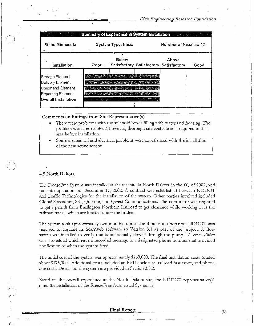
4.5 North Dakota
The FreezeFree System was installed at the test site in North Dakota in the fall of 2002, andput into operation on December 17, 2002. A contract was established between NDDOTand Traffic Technologies for the installation of the system. Other parties involved includedGlobal Specialties, SSI, Quixote, and Qwest Communications. The contractor was requiredto get a permit from Burlington Northern Railroad to get clearance while working over therailroad tracks, which are located under the bridge.
The system took approximately two months to install and put into operation. NDDOT wasrequired to .upgrade its ScanWeb software to Version 3.1 as part of the project. A flowswitch was installed to verify that liquid actually flowed through the pump. A voice dialerwas also added which gave a recorded incssage to a designated phone number that providednotification of when the systcm fircd.
The initial cost of the systcm was approximately $169,000. The final installation costs totaledabout $173,000. Additional costs includcd an RPU enclosure, railroad insurance, and phoneline costs. Details on the system arc providcd in Section 3.5.2.
Based on the overall experience at the North Dakota site, the NDDOT representative(s)rated the installation of the FreezeFree Automated System as:
Final Report 36
~--------- ---- --- ------------------
Civil Engineering Research Foundadon
Summary ofExperience inSystem Installation ' '. ..
State: North Dakota System Type: Automated Number of Nozzles: 10
Jnstallation
Storage ElementDelivery Element
Command Element
Reporting ElementOverall Installation
PoorBelow
SatisfactoryAbove
Satisfactory Good
Comments on Ratings from Site Representatives
• The pump house installation is fairly easy. It consists of pouring a flat slab andsetting a building on top.
• The installation of the delivery equipment is fairly easy.• The RWIS and sensor installation is fairly simple.
• The installation of the ScanWeb software is easy.
• Installation of the system was done by a contractor and appeared to be fairlysimple.
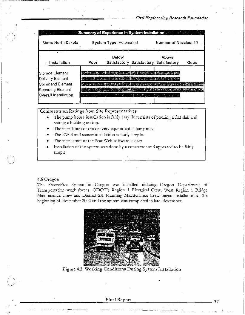
o4.6 OregonThe FreezeFree System in Oregon was installed utilizing Oregon Department ofTransportation work forces. ODOT's Region 1 Electrical Crew, West Region 1 BridgeMaintenance Crew and District 2A Manning Maintenance Crew began installation at thebeginning of November 2002 and the system was completed in late November.
Figure 4.2: Working Conditions During System Installation
o__________________-=F::..,:i=n=a=l..::.R.:..:e::.lp::...:o:..:r:...:.t---- 37
()'.~.__/'
o
Civil Engineering Research Foundadon
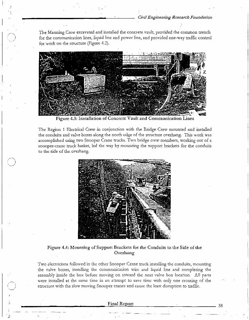
The Manning Crew excavated and installed the concrete vault, provided the common trenchfor the communication lines, liquid line and power line, and provided one-way traffic controlfor work on the ?tructure (Figure 4.2).
.boot:...---2. '.
Figure 4.3: Installation of Concrete Vault and Communication Lines
The Region 1 Electrical Crew in conjunction with the Bridge Crew mounted and installedthe conduits and valve boxes along the north edge of the structure overhang. This work wasaccomplished using two Snooper Crane trucks. Two bridge crew members, working out of asnooper-crane truck basket, led the way by mounting the support brackets for the conduitsto the side of the overhang.
Figure 4.4: Mounting of Support Brackets for the Conduits to the Side of theOverhang
Two electricians followed in the other Snooper Crane truck installing the conduits, mountingthe valve boxes, installing the communication wire and liquid line and completing theassembly inside the box before moving on toward the next valve box location. All partswere installed at the same time in an attempt to save time with only one crossing of thestructure with the slow moving Snooper cranes and cause the least disruption to traffic.
Final Report 38
Civil Engineering Research Foundation
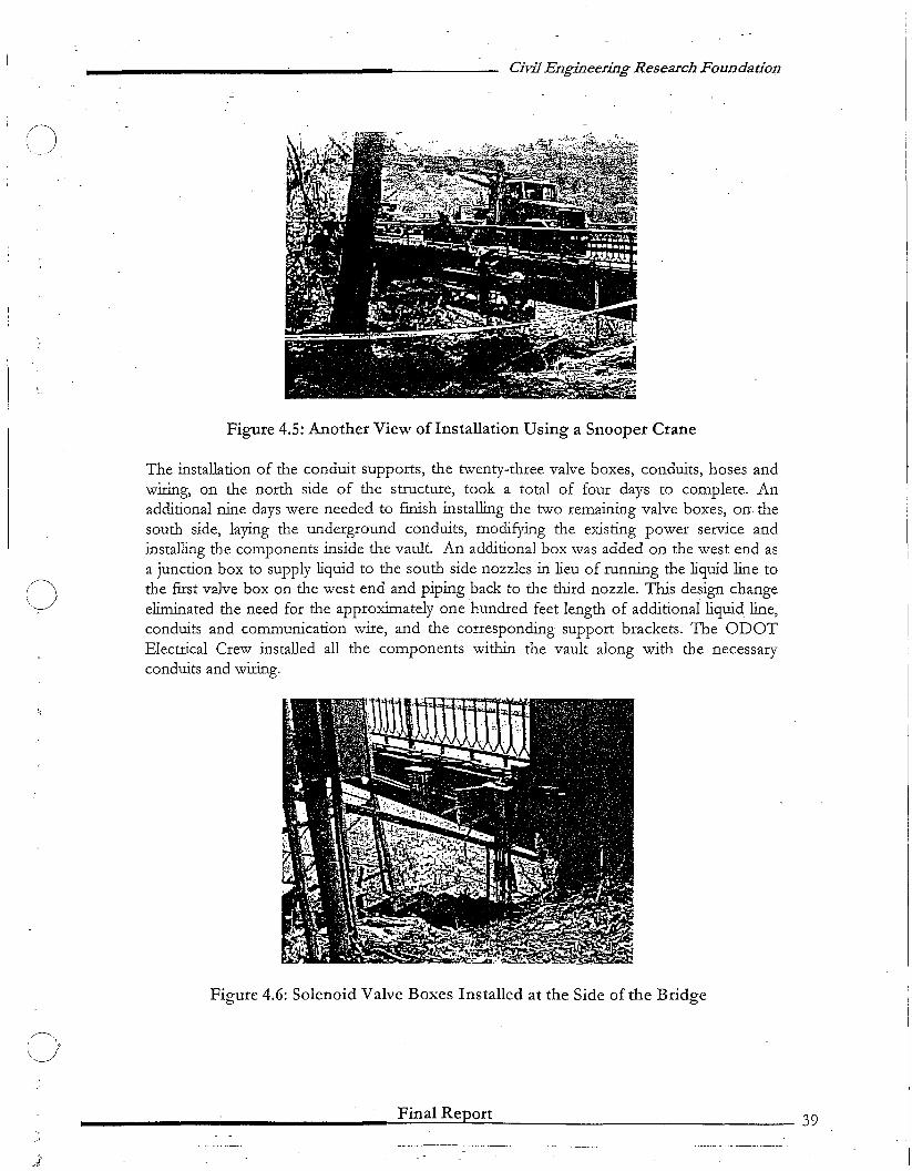
Figure 4.5: Another View of Installation Using a Snooper Crane
The installation of the conduit supports, the twenty-three valve boxes, conduits, hoses andwiring, on the north side of the structure, took a total of four days to complete. Anadditional nine days were needed to fInish installing the two remaining valve boxes, orr thesouth side, laying the underground conduits, modifying the existing power service andinstalling the components inside the vault. An additional box was added on the west end asa junction box to supply liquid to the south side nozzles in lieu of running the liquid line tothe fIrst valve box on the west end and piping back to the third nozzle. This design changeeliminated the need for the approximately one hundred feet length of additional liquid line,conduits and communication wire, and the corresponding support brackets. The ODOTElectrical Crew installed all the components within the vault along with the necessaryconduits and wiring.
Figure 4.6: Solenoid Valve Boxes Installed at the Side of the Bridge
________________~F..:;::in~a-I-R--=-ep.l:..o..:..r:.:..:t 39

oCivil Engineering Research. Foundation
The"estimated cost of this system was.approximately $165,000. Details on the system areprovided in Section 3.6.2.
Based on the overall experience at the O~egon site, the ODOT represeni:ative(s) rated theinstallation ot the FreezeFree Automated System as:
Summary of Experience in System Installation
State: Oregon System Type: Automated Number of Nozzles: 25
Installation performed by outside representative. Rating information not available
Installation
Storage Element
Delivery ElementCommand Element
Reporting ElementOverall Installation
PoorBelow
SatisfactoryAbove
Satisfactory Good
(J
.J-
*No comments on ratings from site representative(s)
4.7 Summary of Ratings fOf System Installation
Figure 4.6 shows a summary rating of system installation based on the input received fromthe representatives and personnel responsible for the test sites.
________________-=F..::.in=al:...,:R:...:...:.e.c:p..::.o.:.:ft=--- 40

Civil Engineering Research Foundation
.'1I9iNot Applicable
~i~~$j,
•
Good
Not Applicable
Below AboveSatisfactory Satisfactory SatisfactoryPoor
CJStora e Element
A Maryland
A Wisconsin-K
N Wisconsin-R
B Minnesota
A North Dakota
A Oregon
Delivery ElementA Maryland
A Wisconsin-K
N Wisconsin-R
B Minnesota
A North Dakota
A Oregon
Command ElementA MarylandA Wisconsin-K
N Wisconsin-R
B Minnesota
A North Dakota
0 A Oregon
Reportin ElementA Maryland
A Wisconsin-KN Wisconsin-R
B Minnesota
A North Dakota
A Oregon
OVERALLA Maryland
A Wisconsin-K
N Wisconsin-R
B Minnesota
A North Dakota
A Oregon
A =Automated; B =Basic; N =Nitro
Figure 4.7: Summary of System Installation Ratings
Final Report 41

C)
o
o
Civil Engineering Research Foundadon .
. Chapter 5: Operation & Maintenance
This chapter briefly introduces the operation of the FreezeFree system as described by themanufacturer, followed by the recommended periodic maintepance o·f the varjous·components of the system. It then documents a summary of experience with operation andmaintenance of the system at the test sites for the past winter seasons, highlighting anyoperational and maintenance issues that were encountered, and the corrective actions thatwere taken. As mentioned earlier in this report, each test site is unique in terms of the typeof installation. Moreover, at each site, the system has evolved over time due to variousrepairs, replacements, adjustments, and upgrades. That is why, in addition to presenting -asummary of experience with operating and maintaining the system at each of the sites,anecdotal ratings representing the views of personnel responsible for operating, andmaintaining the system at each of the sites are presented at the end of this chapter.
5.1 Operation
The FreezeFree System operates under a simple sequence of events from the point ofactivation. It dispenses a liquid anti-icing agent by pumping the chemical through a series ofhigh-pressure spray nozzles, individually controlled by a series of solenoid valves. Uponactivation, the system energizes a motorized pump and automatically sequences the solenoidvalves to spray the anti-icing liquid over the targeted area. A programmable controlleractivates the motorized pump to bring the system to its operating pressure. An anti-icingchemical is circulated by the pump through an overpressure relief valve back to the storagetank to provide agitation of the solution. A series of solenoid valves is then sequentiallyopened and closed to purge air from the system and dispense the anti-icing chemical. Theanti-icing cycle is automatically activated, and can also be initiated remotely via telephone, orby manually pushing a button at the controller assembly.
Automatic activation of the FreezeFree Automated system is provided with an ice predictionsystem employed to accurately measure pavement surface conditions. The ice predictionsystem utilizes a pavement sensor that uses electrical conductivity measurements, surfacetemperature, and optical measurements to determine the surface state. Depending on theparticular system design, atmospheric sensors may also be employed. From the measureddata, water-layer thickness, depression of the freezing point, and chemical concentration arecalculated to provide ice and frost warning conditions. A computer algorithm uses themeasured and calculated data to automatically activate the FreezeFree Automated systemwhen icing conditions are predicted.
In the case of the FreezeFree Nitro System, upon activation by manual push-button orremote pager, the fluid levels in the pressure tank and storage tank are checked. If thestorage tank level is adequate, a vent opens on the pressure tank assembly to bleed off anysystem pressure. After 2 Vz minutes, a supply valve opens to allow anti-icing chemical toflow by gravity from the storage tank to the pressure tank. When the pressure tank is filled,a solenoid valve on the gas regulator assembly opens and nitrogen pressurizes the systemuntil the system operating pressure (150 psi) is reached. The spray valves are sequentiallyopened for one second each, one second apart. Upon completion of the spraying cycle, thesystem re-pressurizes to 150 psi and completes a second spray cycle.
________________-::..F~in-..:a:..;,..l....:.R-e.:..pl-o.:..:r:...:t--- 42
o
o
Civil Engineering Research Foundation
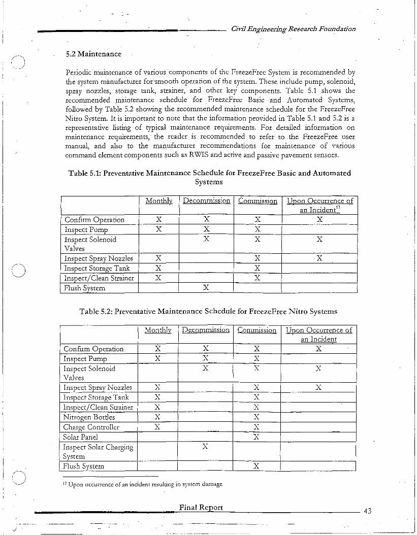
5.2 Maintenance
Periodic maintenance of various components of the FreezeFree System is recommended bythe system manufacturer for-smooth -operation of the system. These include pump, solenoid,spray nozzles, storage tank, strainer, and other key components. Table 5.1 shows therecommended maintenance schedule for _FreezeFree Basic and Automated Systems,followed by Table 5.2 showing the recommended maintenance schedule for the FreezeFreeNitro System. It is important to note that theinformation provided in Table 5.1 and 5.2 is arepresentative listing of typical maintenance requirements. For detailed information onmaintenance requirements; the reader is recommended to refer to the FreezeFree usermanual, and also to the manufacturer recorru~endations for maintenance of variouscommand element components such as RWIS and active and passive pavement sensors.
Table 5.1: Preventative Maintenance Schedule for FreezeFree Basic and AutomatedSystems
Monthly Decommission Commission Upon Occurrence ofan Incident17
ConfIrm Operation X X X XInspect Pump X X XInspect Solenoid X X XValvesInspect Spray Nozzles X X XInspect Storage Tank X XInspect/Clean Strainer X XFlush System X
Table 5.2: Preventative Maintenance Schedule for FreezeFree Nitro Systems
Monthly Decommission Commission Upon Occurrence ofan Incident
ConfIrm Operation X- X X XInspect Pump X X XInspect Solenoid X X XValvesInspect Spray Nozzles X X XInspect Storage Tank X XInspect/Clean Strainer X XNitrogen Bottles X XCharge Controller X XSolar Panel XInspect Solar Charging XSystemFlush System X
17 Upon occurrence of an incident resulting in system damage
_______________..__,....;:.:F....:.i-n-a-I-R-e.....p....;o-r....;t-- 43
----- ----.------------------ - - - ---------------------'
CJ
(J
Civil Engineering Research Foundation
5.3 Summary of Experience at the Test Sites
This section summarizes the experience of the personnel at the test sites in operating andmaintaining the system. The information presented, for the most part, was summarized fromthe documents submitted directly by tlle site representatives, and from information gatheredfrom electronic and telephonic communication with tlle site representatives and fieldpersonnel.
5.3.1 Maryland
The Maryland State Highway Agency (lVIDSHA) representative(s), who are responsible forthe operation and maintenance of the FreezeFree system, provided the following commentsand observations:
a) Winter 2002 - 2003
Odober 18. 2002 to December 27. 2002
The system activated a total bf 22 times during this time period. Several mechanicalproblems were experienced during this time period. MDSHA also had some difficultyunderstanding why the system was activating (or not activating) when certain weatherconditions existed as indicated by the data that was being reported by the ScanWeb interface.Problems during this tin1e period included:
• An activation on October 18, 2002 did not log into the Device History. The RPUwas monitoring the wrong analog input channel. This problem was corrected by SSIfrom their St. Louis office.
• The system sprayed tlle westbound span only and would not shut off. The problemwas identified as excessive voltage between the RPU and the spray controller. SSIinstalled a new Viking 2000 dialer and a 5 Volt power supply to correct the problem.The system was down from October 22,2002 until October 31,2002 because of tlusproblem.
• On November 4, 2002, it was discovered tlnt the tank was losing fluid. The tanklevel had dropped by 44 gallons between November 1, 2002 and Novem.ber 4, 2002and the system had not activated according to the Device History. SSI personnelcame to the site on November 8, 2002 after MDSHA personnel had found tlle leakat nozzle D7. The leak was stopped by disassembling and cleaning tlle solenoidassembly.
• On November 15, 2002, MDSHA manually activated tlle system. Nozzle E12 beganspraying continuously. The problem was identified as a bad address module in tllevalve control box. The system was down from November 15,2002 until November22, 2002, \vaiting for a new address module to be installed.
• It was observed tllat some side-mounted nozzles had rotated, resulting inmisdirected spray. Tlus problem was fLxed by grouting in the holes drilled to installthe nozzles. -
________________-F-in-a-I-R-ep'--or-t---- ---:- 44
C)
___________________----- -Civil Engineering Research Foundation
Some of the questions raised by MDSHA when they looked at the data being reported fromthe ScanWebsite included:
• Why was the system not activating in a "Snow Ice Warning" surface statUs?• Why was the data indicating an activation when there was none?• Why was the system activating when the surface status was "Wet" or "Chemical
Wet"?
During this time period, there were two significant storms. From December 4, 2002 throughDecember 6, 2002, a total of 7 inches of snow was received (the system activated 3 times).On December 24, 2002 and December 25, 2002, a total of 7 inches of snow was received(the system activated 2 times).
Duember 27. 2002 to March 4. 2003
The Freeze Free System did not function properly during this time period. The RPU calledfor the sprayer to activate a total of 77 times but there was no response. At the January 8,2003 meeting SSI could not give a defInitive answer as to why the system was not working.They proposed to improve the system by installing new ESS software along with activesensors. These improvements would hopefully allow MDSHA staff to have a betterunderstanding of the spray logic when the system activates. SSI advised that it may be thesummer of 2003 before these improvements could be implemented.
• On January 17, 2003, Energy Absorption advised that they believed the eXlStlngproblem with the system was being caused by a faulty Relay 8 module. On January21, 2003, a new Relay 8 module was installed. MDSHA advised that the systemshould now function properly.
• On January 22,2003, the system activated automatically 4 times during late morning.It was discovered that nozzle E6 was spraying continuously and the system wasspraying a dry bridge deck. The precipitation sensor was indicating precipitationalthough it was sunny and clear. The system was shut down and SSI was advised.
• On January 28, 2003, Contracting Technology Inc. of Imperial, Missouri installedtwo Frensor active sensors and one FP 2000 passive sensor. SSI installed a newaddress module at nozzle E6. The system was test-fIred prior to installing the activesensors so the spray pattern could be viewed. This allowed the contractor to properlyposition the sensors. Upon activation, deicer fluid gushed from valve control box B7(the %" supply line had come off the solenoid assembly). After repairs were made atB7, the system was activated again. Nozzle E5 sprayed continuously. It was disabledby removing the fuse in the valve control box, and the system was activated again.This time Nozzle B8 sprayed continuously. The system was shut down. There wasno further action taken at the site by the vendors until March 4, 2003.
During this time period (December 27, 2002 to March 4, 2003) a total of 78 inches of snowwas received, and the RPU called for the sprayer to activate 77 times.
_______--.-. ~F.=in=a=l:...::R:.:.e=.Jpt:..:o::.:r:.:.t-- 45

()
o
()
Cil'iJEngineering Research Foundation
.March 4,2003 to A,pril9, 2003On March 4-7, 2003, representatives from Energy Absorption, SSI, National CapitalIndustries and "H& W Contracting were on site. They performed the following:
• Inspected .all valve control boxes for leaks.• Placed hose clamps on all 3//' connections at the solenoid assemblies,• Installed new address modules at ES and B8.• Caulked around spray nozzles to prevent rotation. Calibrated the active sensors.• Updated the RPU code to ESS 1.6.• Installed new processor board and power supply.
The system was test-fired three times (twice manually at the site and once remotely from St.Louis). There were no visible problems during the three activations. From March 6, 2003 toApril 9, 2003, the system activated 25 times. There were no problems experienced with thenozzles, connections, address modules, etc. However, the precipitation sensor had arecurring problem. It indicated precipitation when there is none. MDSHA continues to havedifficulty understanding the spray logic when compared to actual conditions that existedwhen the system activated.
b) Winter 2003-2004
• The FreezeFree System was re-commissioned on November 4, 2003. During thewinter of 2003-2004, a total of 74 inches of snow was received at the site. Thesystem activated a total of 137 times between November 13, 2003 and April 2, 2004.
• The system did not experience any significant mechanical problems during thisperiod. During re-commissioning, three address relays and one solenoid werereplaced.
• The main concern centered on the inability of active sensors to report a freeze pointat the onset of deck coverage. The significance of tlns situation is that the system hasto have a freeze point to compare to the surface temperature before the spray systemcan activate. Maryland State Highway Administration (MDSHA) has recorded anddocumented a number of instances where the system had not activated even afterreceiving heavy snow squalls on the deck.
• In February of 2004, based on the recommendation of tl1e manufacturer of theactive sensor, SSI representative advised MDSHA to add two additional sensors.This suggestion was accepted by MDSHA. They are currently waiting to get aninstallation date from SST.
c) Anecdotal RatingBased on the overall experience at the Maryland site, tl1e MDSHA representative(s) rated tl1eFreezeFree Automated System as:
Final Report 46
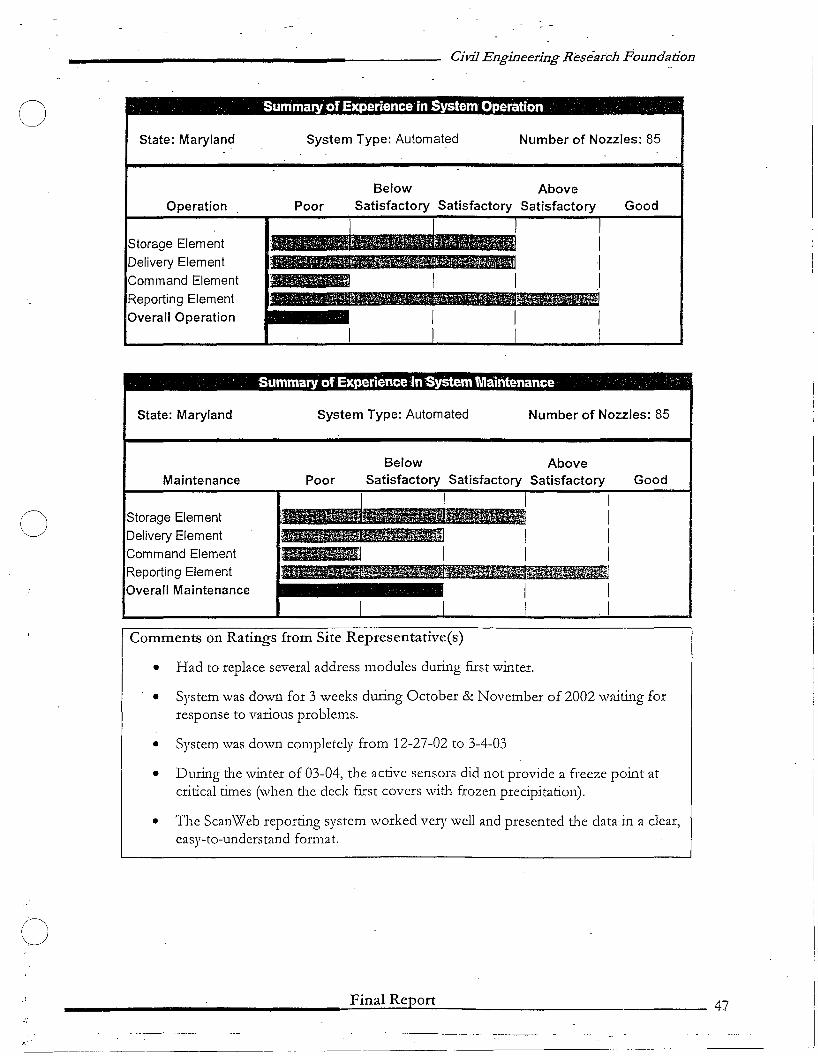
Civil Engineering Research Foundadon
, ' Summary ofExperience in System Operation '
State: Maryland System Type: Automat~d Number of Nozzles: 85
Operation
Storage ElementDelivery Element
Command Element
Reporting ElementOverall Operation
PoorBelow
SatisfactoryAbove
Satisfactory Good
Summary of Experience inSystem Maintenance '
State: Maryland System Type: Automated Number of Nozzles: 85
oMaintenance
Storage ElementDelivery ElementCommand ElementReporting ElementOverall Maintenance
PoorBelow
SatisfactoryAbove
Satisfactory Satisfactory Good
o
F-'.-
Comments on Ratings from Site Reprcsentative(s)
• Had to replace several address modules during fIrst winter.
• System was down for 3 weeks during October & November of 2002 'waiting forresponse to various problems.
• System was down completely from 12-27-02 to 3-4-03
• During the winter of 03-04, the active sensors did not provide a freeze point atcritical times (when the deck fIrst covers with frozen precipitation).
• The ScanWeb reporting system worked very well and presented the data in a clear,easy-to-understand format.
________________-:.;.F-in-a-I-R-cp'---'-or-.:t----- , 47
--- ...' ".. _.----- .

o
o
(J
/
Civil Engineering Research Foundation
_5.3.2 Wisconsin-K
The County Highway Department personnel from Kenosha County, who are responsible forthe operation and maintenance of the FreezeFree system, provided the following commentsand observations:-
a) Prior to 2003-2004 Winter Season• After the system became operational in January, 2000, there were no opportunities to
activate the system during the remainder of the 1999-2000 winter season.
• Due to over-activation of the system, WisDOT personnel requcsted that the automaticactivation codes be changed in October 2000 and December 2000 to be morerepresentative of winter weather in Kenosha County.
• The tank level monitor failed and the motor had to be replaced after it burned out.Minor warranty work was performed by Energy Absorption Systems, Inc. personnel onthe system equipment.
• There was some damage caused to the telephone line and electrical wiring installationdue to rodents entering the pump house.
• In general, the system worked well. The automatic activation parameters were moreconsistent. The Vaisala moisture sensor worked well, and the system did not over'activate.
b) 2003-2004 Winter Season• In 2003-2004 winter season, all nozzle plungers were replaced by units treated with zinc
coating because the spray nozzles had become inoperative due to corrosion of thenozzle plunger by the magnesium chloride product.
• The system was more reliable than the past winter seasons. The pump house was sealedto prevent rodents from accessing the wiring. Activation parameters were kept the sameas those of the previous season.
• There were various problems encountered with the voice dialer during this period.These problems were related to over-reporting of "low fluid" notification, and thesystem consistently not reporting spray activation. The voice dialer was later repaired,but it continued not reporting spray activation. It was learned that the pressure gaugewas not reading properly, and was not providing proper pressure to activate the dialer.There wcre also incidents when the dialer reported system activation when none hadoccurred according to the spray log history. These problems were resolved in February2004, and did not occur since then.
c) Anecdotal RatingBased on the overall experience at the Wisconsin-K site, the WisDOT represcntative(s) ratedthe FreczeFrec Automated System as:
Final Report 48
-------------------------------------------------'
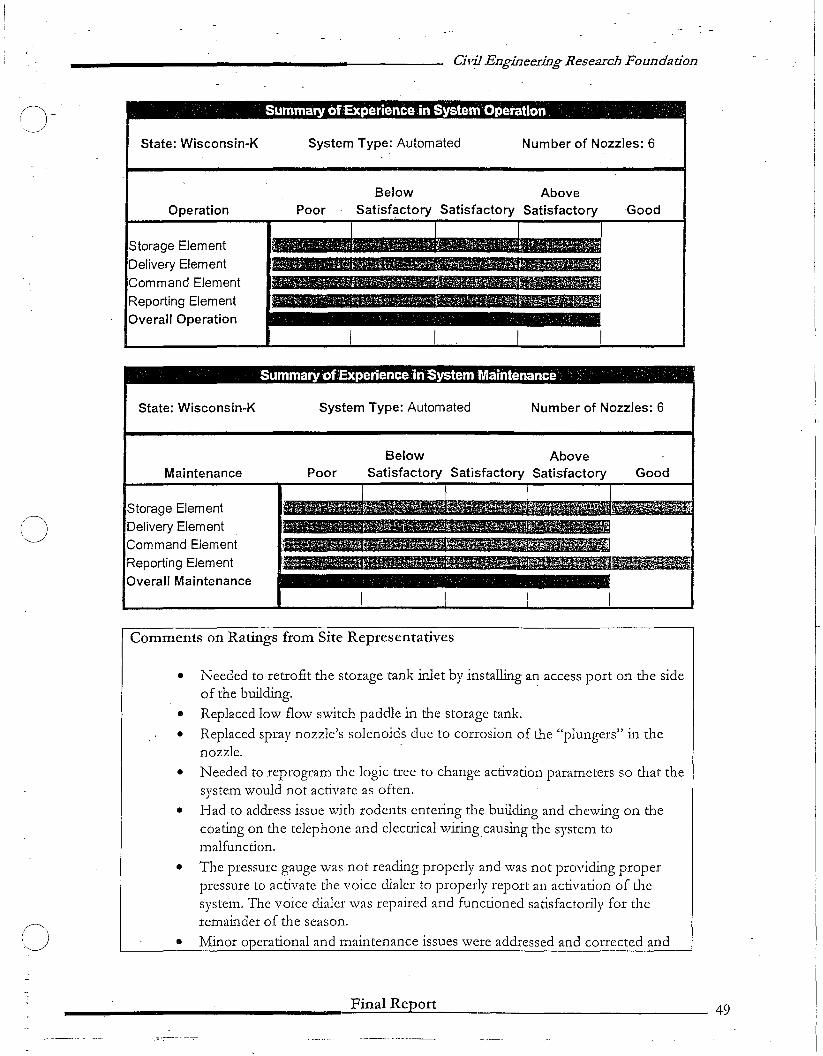
n-Civil Engineering Research Foundation
Summary of£Xperience in System Operation .' .
State: Wisconsin-K System Type: Automated Number of Nozzles: 6
Operation PoorBelow Above
Satisfactory Satisfactory Satisfactory Good
Storage ElementDelivery Element
Command Element
Reporting ElementOverall Operation
Summary ofExperience 1n System Maintenance' , , .
State: Wisconsin-K System Type: Automated Number of Nozzles: 6
Maintenance PoorBelow Above
Satisfactory Satisfactory Satisfactory Good
oStorage ElementDelivery ElementCommand ElementReporting ElementOverall Maintenance
. f
o
Comments on Ratings from Site Representatives
• Needed to retrofit the storage tank inlet by installing an access port on the sideof the building. .
• Replaced low flow switch paddle in the storage tank.
• Replaced spray nozzle's solenoids due to corrosion of the "plungers" in thenozzle. .
• Needed to reprogram the logic tree to change activation parameters so that thesystem would not activate as often.
• Had to address issue with rodents entering the building and chewing on thecoating on the telephone and electrical wiringcausing the system tomalfunction.
• The pressure gauge was not reading properly and was not providing properpressure to activate the voice dialer to properly report an activation of thesystem. The voice dialer was repaired and functioned satisfactorily for theremainder of the season.
• Minor operational and maintenance issues were addressed and corrected and
Final Report 49
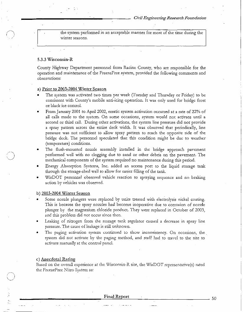
o
o
o
Civil Engineering Research Foundation
the system -performed in an acceptable manner for most of the time during thewinter seasons.
5.3.3 Wisconsin-R
County Highway Department personnel from Racine County, who are responsible for theoperation and maintenance of the FreezeFree system, provided the following comments andobservations:
a) Prior to 2003-2004 Winter Season
• The system was activated two times per week (fuesday and Thursday or Friday) to beconsistent with County's mobile anti-icing operation. It was only used for bridge frostor black ice control.
• From January 2001 to April 2002, erratic system activation occurred at a rate of 22% ofall calls made to the system. On some occasions, system would not activate until asecond or third call. During other activations, the system line pressure did not providea spray pattern across the entire deck width. It was observed that periodically, linepressure was not sufficient to allow spray pattern to reach the opposite side of thebridge deck. The personnel speculated that this condition might be due to weather(temperature) conditions.
• The flush-mounted nozzle assembly installed in the bridge approach pavementperformed well with no clogging due to sand or other debris on the pavement. Themechanical components of the system required no maintenance during this period.
• Energy Absorption Systems, Inc. added an access port to the liquid storage tankthrough the storage-shed wall to allow for easier filling of the tank.
• WisDOT personnel observed vehicle reaction to spraying sequence and no brakingaction by vehicles was observed.
b) 2003-2004 Winter Season
• Some nozzle plungers were replaced by units treated with electrolysis nickel coating.This is because the spray nozzles had become inoperative due to corrosion of nozzleplunger by the magnesium chloride product. They were replaced in October of 2003,and this problem did not occur since then.
• Leaking of nitrogen from the storage tank regulator caused a decrease in spray linepressure. The cause of leakage is still unknown.
• The paging activation system continued to show inconsistency. On occasions, thesystem did not activate by the paging method, and staff had to travel to the site toactivate manually at the control panel.
c) Anecdotal RatingBased on the overall experience at the Wisconsin-R site, the WisDOT representative(s) ratedthe FreezeFree Nitro System as:
Final Report 50
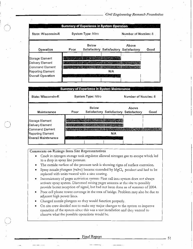
Civil Engineering Research Foundadon
Summary ofExperience in System Operation'
State: Wisconsin-R System Type: Nitro Number of Nozzles: 8
Operation
Storage ElementDelivery Element
Command Element
Reporting ElementOverall Operation
PoorBelow
Satisfactory
N/A
AboveSatisfactory Good
SummaryofExperience in System Maintenance '
State: Wisconsin-R System Type: Nitro Number of Nozzles: 8
GoodAbove
SatisfactoryBelow
SatisfactoryPoor
.........~N/A
Maintenance
Storage ElementDelivery ElementCommand ElementReporting ElementOverall Maintenance
C)
o
Comments on Ratings from Site Representatives
• Crack in nitrogen storage tank regulator allowed nitrogen gas to escape which ledto a drop in spray line pressure.
• The outside surface of the pressure tank is showing signs of surface corrosion.
• Spray nozzle plungers (valve) became corroded by MgClz product and had to bereplaced with units treated with a zinc coating.
• Inconsistency of pager activation system: First call into system does not alwaysactivate spray system. Discussed raising pager antenna at the site to possiblyprovide better reception of signal, but had not been done as of summer of 2004.
• Poor cell phone tower coverage in the area of bridge. Problem may also be due toadjacent high power lines.
• Changed nozzle plungers so they would function properly.
• On site crew decided not to make any major changes to the system to improveoperation of the system since this was a test installation and they wanted toobserve what the possible operations would be.
_________________F-in-al-R-ep....o-r-.:t 51

Civil Engineering Research Foundadon
5.3.4 Minnesota
The FreezeFree Basic System installed in the City of Dlliuth, :Minnesota, works under simplemanual operation. The system ·did nof experience any significant problems during the pastwinter seasons, except the system failures in March of 2002 and 2003 due to the entry ofwater into the boxes that house the solenoids for the nozzle. Observations indicate that thesystem works as it was designed to spray chemicals on tile roadway. The frequency of sitevisits is dictated by plowing or sanding requirements.
Anecdotal RatingBased on the overall experience at the Minnesota site, the MNDOT representative(s) ratedthe FreezeFree Basic System as:
SummaryofExperience in System Operation " . '
State: Minnesota System Type: Basic Number of Nozzles: 12
o
Operation
Storage Element
Delivery Element
Command Element
Reporting Element
Overall Operation
Below AbovePoor Satisfactory Satisfactory Satisfactory
:III
Good
.' . Sum'maryoJExperiencelnSystemMaintenance " : "
State: Minnesota System Type: Basic Number of Nozzles: 12
Cj
Maintenance
Storage ElementDelivery Element
Command Element
Reporting Element
Overall Maintenance
PoorBelow
SatisfactoryAbove
Satisfactory Good
Final Report 52
C)
(J
()
Civil Engineering Research Foundation
Comments on Ratings from Site Representatives
• The storage system is adequate and meets the department's needs.
• Operation and Maintenance of the system are generally in the acceptable rangesfor MNDOT's needs. There is a float problem inside the tank, where the tankneeds to be drained and a person needs to climb inside it. There needs to be aneasier solution for this problem.
5.3.5 North Dakota
The North Dakota Department of Transportation (NDDOT) representative(s), who areresponsible for the operation and maintenance of the FreezeFree system, provided thefollowing comments and observations:
a) Prior to 2003-2004 Winter Season
• The system only required general maintenance such as flushing fresh water through thesystem at the end of the winter season. NDDOT has had problems with rodents gettinginto the pump house, and has been required to keep rat poison in the building.
• The FP 2000 sensor does a satisfactory job; however, sediments can collect in thesampling cup and record a damp or wet deck condition when the deck is actually dry.The passive sensor also does not work when there are multiple chemicals on theroadway or bridge deck.
• Daily site visits to confrrm computer data found that the system indicated it had frredwhen it actually did not. NDDOT found this out by marking the liquid level on thetank along with a date. Several trips were made by SSI to try and fIx this problem. Whenthe system was working, several instances were observed in which the system indicatedit fIred and it did when it should have.
• Numerous problems were encountered with the automated bridge spray system. As aresult, the entire controller for the system was redesigned.. The RWIS system wasupgraded in 2002. The upgraded RWIS included a new FP-2000 roadway sensor toprovide roadway temperatures and chemical freeze points. The FP-2000 sensor is apassive sensor that relies on electrical conductivity readings to calculate the freeze pointof the chemical present on the roadway. Electrical conductivity readings are onlyaccurate with the FP 2000 sensor if only one chemical is used or a known mL"ture ofchemicals is used for anti-icing or dc-icing. It is common practice for the NDDOT toapply a mixture of salt and sand to roadways as a de-icing practice for snow and icecontrol. The application of salt to the structures was detected by the FP 2000 roadwaysensors and skewed the conductivity rcadings that were developed for potassium acetate(CF-7). The computer algorithm was based on strictly potassium acetate (CF~7), andtl1crefore the computer logic programmed to trigger tl1e system providcd erroneousinformation to the controller.
Final Report S3
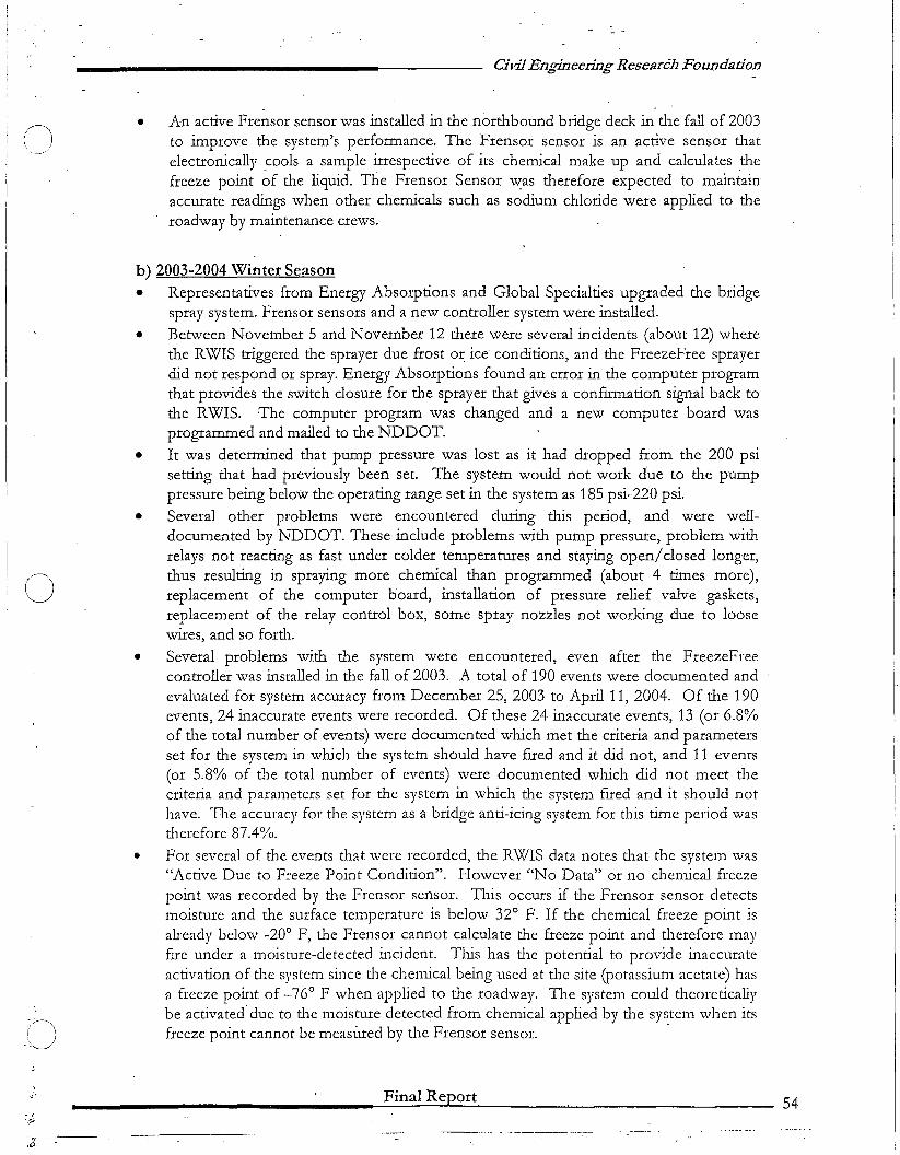
•
Civil Engineering Research Foundation
An active Frensor sensor was installed in the northbound bridge deck in the fall of 2003to improve the system's performance. The Frensor sensor is an active sensor thatelectronically .cools a sample irrespective of its chemical make up and calculates thefreeze point of the liquid. The Frensor Sensor w:as therefore expected to maintainaccurate readings when other chemicals such as sodium chloride were applied to theroadway by maintenance crews.
o
()
. ,'.~
b) 2003-2004 Winter Season• Representatives from Energy Absorptions and Global Specialties upgraded the bridge
spray system. Frensor sensors and a new controller system were installed.
• Between November 5 and November 12 there were several incidents (about 12) wherethe RWIS triggered the sprayer due frost or ice conditions, and the FreezeFree sprayerdid not respond or spray. Energy Absorptions found an error in the computer programthat provides the switch closure for the sprayer that gives a confIrmation signal back tothe RWIS. The computer program was changed and a new computer board wasprogrammed and mailed to the NDDOT.
• It was determined that pump pressure was lost as it had dropped from the 200 psisetting that had previously been set. The system would not work due to the pumppressure being below the operating range set in the system as 185 psi-220 psi.
• Several other problems were encountered during this period, and were welldocumented by NDDOT. These include problems with pump pressure, problem withrelays not reacting as fast under colder temperatures and staying open/closed longer,thus resulting in spraying more chemical than programmed (about 4 times more),replacement of the computer board, installation of pressure relief valve gaskets,replacement of the relay control box, some spray nozzles not working due to loosewires, and so forth.
• Several problems with the system were encountered, even after the FreezeFreecontroller was installed in the fall of 2003. A total of 190 events were documented andevaluated for system accuracy from December 25, 2003 to April 11, 2004. Of the 190events, 24 inaccurate events were recorded. Of these 24 inaccurate events, 13 (or 6.8%of the total number of events) were documented which met the criteria and parametersset for the system in which the system should have fued and it did not, and 11 events(or 5.8% of the total number of events) were documented which did not meet thecriteria and parameters set for the system in which the system fIred and it should nothave. The accuracy for the system as a bridge anti-icing system for tlus time period wastherefore 87.4%.
• For several of the events that were recorded, the RWIS data notes that the system was"Active Due to Freeze Point Condition". However "No Data" or no chemical freezepoint was recorded by the Frensor sensor. This occurs if the Frensor sensor detectsmoisture and the surface temperature is below 320 F. If the chemical freeze point isalready below _200 F, the Frensor cannot calculate the freeze point and therefore mayfIre under a moisture-detected incident. This has the potential to provide inaccurateactivation of the system since tl1e cl1enucal being used at the site (potassium acetate) hasa freeze point of _76 0 F when applied to the roadway. The system could theoreticallybe activated due to the moisture detected from chemical applied by the system when itsfreeze point cannot be measured by the Frensor sensor. .
________________~F-in-a-l-R-e...Jp'-o-'-r-=t- ~ 54
:(,.~...--
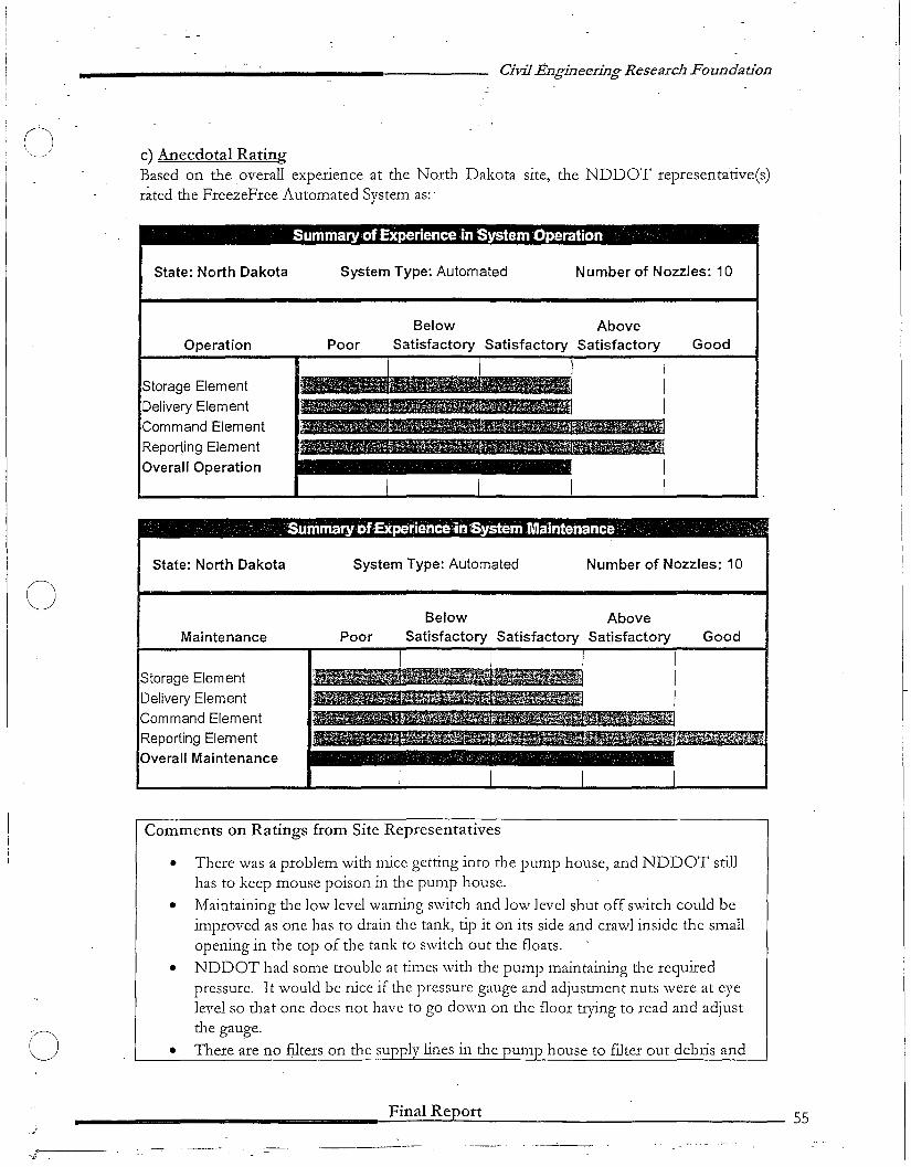
oCivil Engineering Research Foundadon
c) Anecdotal RatingBased on the overall experience at the North Dakota site, the NDDOT representative(s)rated the FreezeFree Automated System as:'
Summary ofExperience in System Operation '
State: North Dakota System Type: Automated Number of Nozzles: 10
Operation
Storage Element
Delivery ElementCommand Element
Reporting ElementOverall Operation
PoorBelow
SatisfactoryAbove
Satisfactory Good
'SummaryofExperienceinSystem Maintenance .' ,:",..;
System Type: Automated Number of Nozzles: 10
oState: North Dakota
Maintenance
Storage ElementDelivery ElementCommand ElementReporting ElementOverall Maintenance
PoorBelow
SatisfactoryAbove
Satisfactory Good
. ,~ ~.
o
Comments on Ratings from Site Representatives
• There was a problem with mice getting into the pump house, and NDDOT stillhas to keep mouse poison in the pump house.
• Maintaining the low level warning switch and low level shut off switch could beimproved as one has to drain the tank, tip it on its side and crawl inside the smallopening in the top of the tank to switch out the floats.
• NDDOT had some trouble at times with the punlp maintaining the requiredpressure. It would be nice if the pressure gauge and adjustment nuts were at eyelevel so that one does not have to go down on the floor trying to read and adjustthe gauge.
• There are no fliters on the supply lines in tne pump house to fliter out debris and
Final Report 55

(J
o
CivilEngineering Research Foundation
particles. Several of the electrical lines are not encased in conduit and-have thepotential to become damaged or eaten by rodents.
• The Frensor sensor can calculate a_ freeze point down to _20oP. If the sensordetects moisture and it cannot calculate a freeze point it will activate the system.. Ithas the potential to activate from moisture from the chemicals applied whosefreeze point is below -20°F. .
• The control boxes on the North Dakota System are powder coated paint and arerusting. Some of the bolts that hold the controller box doors shut are rusted off.
• Operating the software is simple and gives good data. It does not give anexplanation of why the system fIred due to freeze point condition, yet no freezepoint is calculated.
• Some maintenance of the output data is required at times. SSI has responded whenadjustments were needed to the output data screen.
• The system in North Dakota operated with an 87% accuracy rate from the timeperiod of December 25, 2003 to April 11 2004 in which data was collected.
• Overall system maintenance is fairly good with the exception of notedimprovement suggestions.
5.3.6 Oregon
The Oregon Department of Transportation (ODOT) representative(s), responsible for theoperation and maintenance of the FreezeFree system, provided the following comments andobservations:
a) Prior to 2003-2004 Winter SeasonNo data was collected due to the following issues:
• During the later part of November and all of December 2002, and part ofJanuary 2003,there was no commercial power due to a storm. However, test firing was completedusing a portable generator. The test appeared to be satisfactory.
• With the power on, the system would not communicate with RWIS. Therefore, theRWIS components were upgraded. R\X!IS existed at tlus site prior to the installation oftlle PreezeFree system.
• There was a problem in tlle common Freeze Free relay board.
• There was a problem with the valves. ODOT thought that the valve box control relayswere burned out (not broken). There was also a problem with control panelcommunication. A new control panel and a line conditioner were installed. The lineconditioner didn't work witll the system, and was unwired. (Apparently, it was not testedwitll the system before being tried in field) ..
• Of tlle valves that were stuck or malfunctioning, two appeared to be due to defectiverelay controls on the bridge, and three to fIve appeared to be malfunctioning due tomechanical problems. A deposit was found in the valve actuators. The deposit could befrom precipitation of tl1e solution tl1at h~d bled through a breather hole in tlle valve
Final Report 56
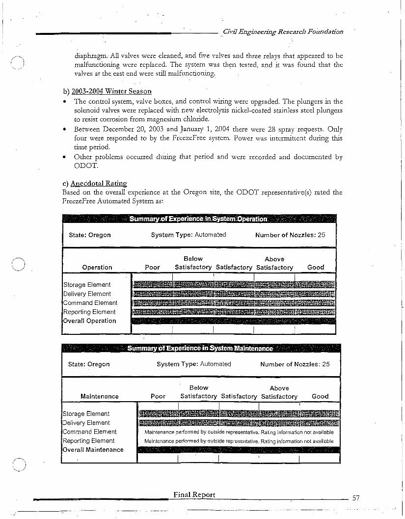
o___________________----- __ Civil Engineering Research Foundadon
diaphragm. All valves were cleaned, and five valves and three relays that appeared to bemalfunctioning were replaced. The system was then tested, and it ,vas found that thevalves at the east end were still malfunctioning._
b) 2003-2004 Winter Season
• The control system, valve boxcs, and control wiring were upgraded. The plungers in thesolenoid valvcs were replaced with new electrolysis nickel-coated stainless steel plungersto resist corrosion from magnesium chloride.
• Betwcen December 20, 2003 and January 1, 2004 there were 28 spray requests. Onlyfour were responded to by the FreezeFree system. Power was intermittent during thistime period.
• Other problems occurred during that period and were recorded and documented byODOT.
c) Anecdotal RatingBased on the overall experience at the Oregon site, the ODOT representative(s) rated theFreezeFree Automated System as:
, Summaty;OfExperience in,System,Operation ,- - ,_". ,,',
State: Oregon System Type: Automated Number of Nozzles: 25
Operation
Storage Element
Delivery Element
Command Element
Reporting Element
Overall Operation
PoorBelow
SatisfactoryAbove
Satisfactory Good
o
Summatyof,Experlence-inSystem Maintenance
State: Oregon System Type: Automated Number of Nozzles: 25
Below AboveMaintenance Poor Satisfactory Satisfactory Satisfactory Good
~i I IStorage Element "Delivery Element ~~~~~Command Element Maintenance performed by outside representative, Rating information not available
Reporting Element Maintenance performed by outside representative. Rating information not available
Overall Maintenance
I I I I
___...... ...... ~F..:.:in:.::..a:.::..I....:.R....:.e.:.Jpt:...o.:.;r:.:t---- ..,....._:,___-----_ 57
,,--------c::-'. -- -, .."--..-,'
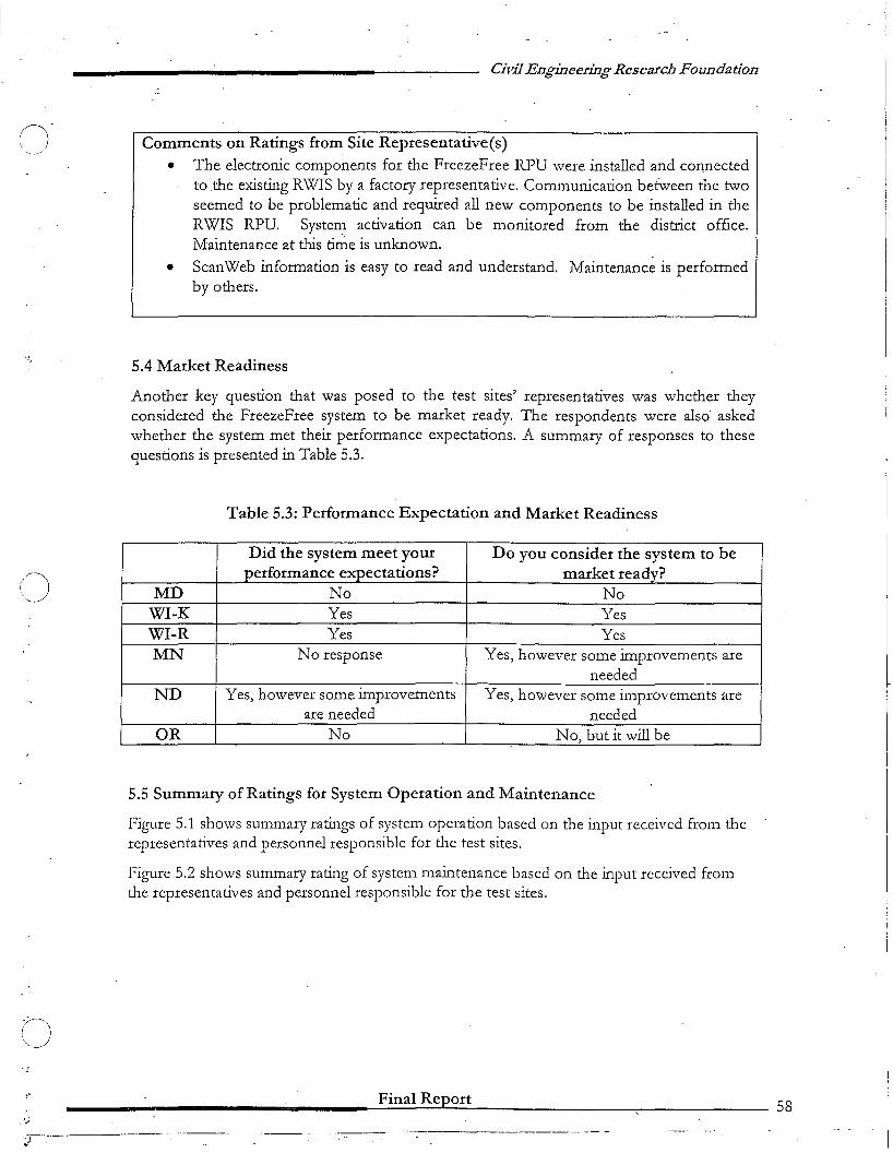
C)
()
()
.".;
Civil Engineering Research Foundation
Comments on Ratings from Site Representative(s)
• The electronic components for the FreezeFree RPU were installed and connectedtothe existing RWIS by a factory representative. Communication between the twoseemed to be problematic and required all new components to be installed in theRWIS RPU. System activation can be monitored from the district office.Maintenance at this t:irrie is unknown.
• ScanWeb infonnation is easy to read and understand. Maintenance is perfonnedby others.
5.4 Market Readiness
Another key question that was posed to the test sites' representatives was whether theyconsidered the FreezeFree system to be market ready. The respondents were also askedwhether the system met their performance expectations. A summary of responses to thesequestions is presented in Table 5.3.
Table 5.3: Performance Expectation and Market Readiness
Did the system meet your Do you consider the system to beperformance expectations? market ready?
MD No NoWI-K Yes YesWI-R Yes YesMN No response Yes, however some improvements are
neededND Yes, however some improvements Yes, however some improvements are
are needed neededOR No No, but it will be
5.5 Summary of Ratings for System Operation and Maintenance
Figure 5.1 shows summary ratings of system operation based on the input received from therepresentatives and personnel responsible for the test sites.
Figure 5.2 shows summary rating of system maintenance based on the input received fromthe representatives and personnel responsible for the test sites.
Final Report 58
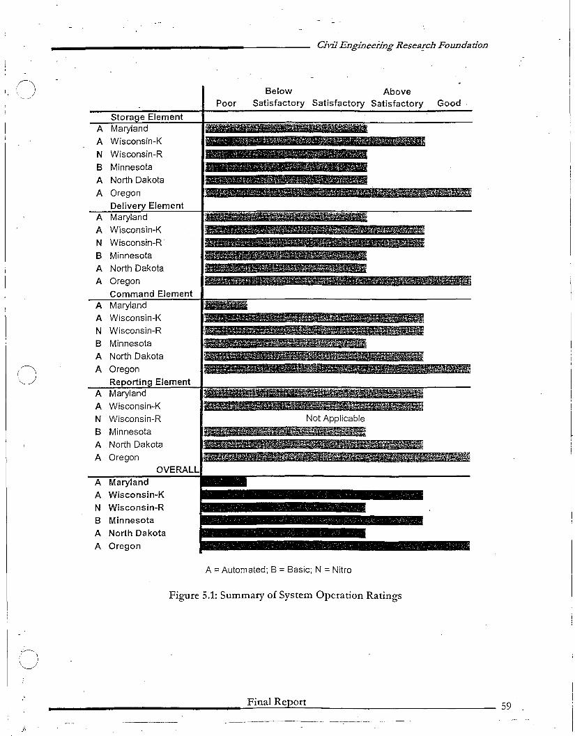
Civil Engin~eringResearch Foundadon
MJIjII!!I'B~,.,..,.,....~
GoodAbove
Satisfactory SatisfactoryBelow
SatisfactoryPoor
Iiiiii&44A~
Not Applicable
()Stora e Element
A Maryland
A Wisconsin-K
N Wisconsin-RB- Minnesota
A North Dakota
A Oregon
Delive ElementA Maryland
A Wisconsin-K
N Wisconsin-R -
B Minnesota
A North Dakota
A Oregon
Command ElementA Maryland
A Wisconsin-K
N Wisconsin-R
B Minnesota
A North Dakota
CJ A Oregon
Reportin ElementA Maryland
A Wisconsin-K
N Wisconsin-R
B Minnesota
A North Dakota
A OregonOVERALL
A Maryland
A Wisconsin-K
N Wisconsin-R
B Minnesota
A North Dakota
A Oregon
A =Automated; B =Basic; N =Nitro
Figure 5.1: Summary of System Operation Ratings
(JFinal Report 59
j,--------------
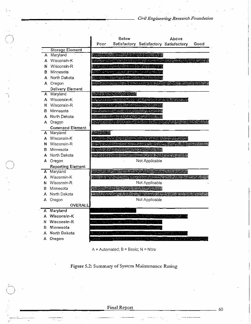
Civil Engineering Research Foundation
oPoor
Below AboveSatisfactory Satisfactory Satisfactory Good
Not Applicable
Not Applicable
....,&&~~
Not Applicable
Stora e ElementA Maryland
A Wisconsin-K
N Wisconsin-R
B Minnesota
A North Dakota
A Oregon
Delive Element.. A Maryland
A Wisconsin-K
N Wisconsin-R
B Minnesota
A North Dakota
A Oreg~n
Command ElementA Maryland
A Wisconsin-K
N Wisconsin-R
B Minnesota
A North Dakota
0A Oregon
Reportin ElementA Maryland
A Wisconsin-K
N Wisconsin-R
B Minnesota
A North Dakota
A OregonOVERALL
A Maryland
A Wisconsin-K
N Wisconsin-R
B Minnesota
A North Dakota
A Oregon
A =Automated; B =Basic; N =Nitro
Figure 5.2: Summary of System Maintenance Rating
-oFinal Report 60
-!
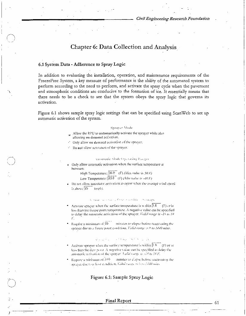
(J
o
Civil Engineering Research Foundation
Chapter-6: Data Collection and Analysis_
6.1 System Data - Adherence to Spray Logic
In addition to evaluating the installation, operation, and maintenance requirements of theFreezeFree System, a key measure of performance is the ability of the automated system toperform according to the need to perform, and activate the spray cycle when the pavementand atmospheric conditions are conducive to the formation of ice, It essentially means thatthere needs to be a check to see that the system obeys the spray logic that governs itsactivation.
Figure 6.1 shows sample spray logic settings that can be specified using ScanWeb to set upautomatic activation of the system.
Spnl~·1.;· '\!'I.;I('
",' !\lIo',\' tlh~ RI'Ll I.(l :lut(lOl:Hic:III~'~,clj\'a[c the ~p":lycr wllik <l1:;a'alkJ'Ning on demand oc.ti\'ntion,
Oniy ailow on dt'lll:tnd ;IGliv;~:i[)r. I.,fliw spr.-l;,cr.
Do nol ~dl(\\\' :,di';;III(\l"i or' \11,' spr:i:"l:r.
• Only .allow <1LJto!1lQtic m:ti".nl!nn wlwn the surCm:c lL::lllx'r;jlUrC isndWL:cn:
High Tcmperilture: ~;5~(i-' l.f) (M....\ ,'(dll,' i.1 51i;-:1
Low Tcmpcr,lHl"c-; 120.0 {F) ..-A/in '''';;i.'<' is ··10 1-"/
• IJl) nLl~ ;dln\\ aUh·ljn~lllC .HC'lh'ntil.l/1 to \"11;"(1.11" \"'h~1i lh~' ~p,·~ra;:.c \,.:1I1d s;h.~{'d
i.'; ;ih,'\'\: [25 - Imph). .
__ '.. : ~, :", I . ;.;!:: j. '~.. '; Il.::>
o
I 'I' '1'~1" 'I'".'\Clfl,'~llt" Srr;IYl~r '-~.. H~n lrlf.~ ";lJ:" ;Jl·l' t(."lnp~Hllllrt.: IS v,'ll un 1.0 (.'.J ~lr ISk'~;; Ibn the li('c-/.~~ IXIII'[ h~mJK'r:lIUr~', /0. n\:.!!-'lIi'.~· \'"llIL' .....:tll b(.' :':PL'('llkdII> dd;;y lhe i1l1lomali .... ill'li\:\til>11 "flh\: ~PI''',''t'I', [·,.;/;d IWI!;,.. ,i,1' -l,': If) /S
','f,
• f{t:yuir-L' ~I Illininll:Il""j" :[,0 Inli',:J:i:'!-\ IP I.:bp:-.:: ~.' .... t~lrl~ rl"'l.(ti·~··~Hil1g thv
)l)raY'cT (illt" ~(,l';1 fl"l't."/.l' plHl'lr. '-."P1HlIli·afl. ,'(,'lid "~".I):"":(· ,i, U to .'4·/0,nins,
. ( ;, .. '
..\t:iiv;'lll' ,;['r,J::<:" '.\ 1,,:11 Il1l' ~t1,.fi\""'· 1,':"p;:r;'llIlrl: ;,,; \\ idlilll:"-p;-'- (1"1 ('I' I,
]...4:-" ilt~~i'J 111t" d.,:',·,';"11 It1'l1 ..... neF:lll\C \ aIu,,' l'illl /"1":- ~p';"~l~iti('d In Ih.:1H:,· 1:1'.:~llIl"'I!n:Ltj~~ :l'~I!',~lll~111 fli illl.· ... pl'i!.yl..... J u/;.. l rllii.~l .'s -l ....· {(.I ,is /:.
• 1·~ ...~qlJlr~~ a !)lil:i:lIl1l1l 1'1" .~~M) jrJll1l1l.l~~ id t·:'.lJ~~;c ht~rl'I:": 1~::H::l!\'~JL~~'I}:: 11: ...;-;P:d:\L'l dol"':: II."' ~'I fl'.."!"! '.:\ Ihli;i\lll. i :d,'J .111 .....~:·l I ........ ,ill ... ·;·N.i ,'111'/0''0
Figure 6.1: Sample Spray Logic
________________-=-F..::in::.a:::I:..:R::.::..=.ep=or:.;t:..------ -61
--------------- .._-_ .. _--_._, -----
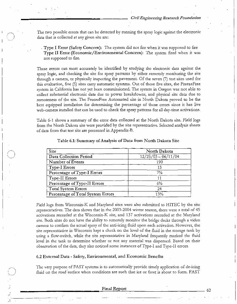
C)
o
o,
"
Civil Engineering Research Foundadon
The two possible errors that can be detected by running the spray logic against the electronicdata that is collected at any given site are:
. Type I Error (Safety Concern): The system did not fire when it was supposed to fIreType II Error (Economic/Environmental Concern): The system fued when it wasnot supposed to fIre.
These errors can most accurately be identifIed by studying the electronic data against thespray logic, and checking the site for spray patterns by either remotely monitoring the sitethrough a camera, or physically inspecting the pavement. Of the seven (7) test sites used forthis evaluation, fIve (5) sites carry automatic systems. Out of these fIve sites, the FreezeFreesystem in California has not yet been commissioned. The system in Oregon was not able tocollect substantial electronic data due' to power breakdowns, and physical site data due toremoteness of the site. The FreezeFree Automated site in North Dakota proved to be thebest equipped installation for determining the percentage of these errors since it has liveweb-camera installed that can be used to check the spray patterns for all day-time activations.
Table 6-1 shows a summary of the error data collected at the North Dakota site. Field logsfrom the North Dakota site were provided by the site representative. Selected analysis sheetsof data from that test site are presented in Appendix-B.
Table 6.1: Summary of Analysis of Data from North Dakota Site
Site North DakotaData Collection Period 12/25/03 - 04/11/04Number of Events 190Type-I Errors 13Percentage of Type-I Errors 7%Type-II Errors 11Percentage of Type-II Errors 6%Total System Errors 24Percentage of Total System Errors 13%
Field logs from Wisconsin-K and Maryland sites were also submitted to HITEC by the siterepresentatives. The data shows that in the 2003-2004 winter season, there were a total of 45activations recorded at the Wisconsin-K site, and 137 activations recorded at the Marylandsite. Both sites do not have the ability to remotely monitor the bridge decks through a videocamera to confirm the actual spray of the anti-icing fluid upon each activation. However, thesite representative in Wisconsin kept a check on the level of the fluid in the storage tank byusing a flow-switch, while the site representative in Maryland frequently marked the fluidlevel in the tank to deternune whetl1er or not any material was dispensed. Based on tl1eirobservation of the data, they also noticed some instances of Type-I and Type-II errors.
6.2 External Data - Safety, Environmental, and Economic Benefits
The very purpose of FAST systems is to automatically provide timely application of de-icingfluid on the road'surface when conditions are such that ice or frost is about to form. FAST
________________~F.:.:in:::a=I:...:R~e=.Jpt:.o.::.:r:.:t:....· ~_~_ _.,..---- 62
o
()
()
Civil Engineering Research Foundation
-systems are intended to deliver an appropriate amount of de-icing fluid onto the road surfacewhen and only when these conditions are met. This would lead to infer that FAST systemscan:
a) Substantially improve traffic safety during inclement weather periods by eliminatingdangerous road surface conditions in the winter season in a timely manner, therebyreducing the number and possibly the seriousness ofcrashes18
;
b) Reduce the quantity of de-icing fluid used and the total amount of such chemicals thatwill find its way into the environment, resulting in reduced environmental impact andoperational costs; and
c) Eliminate other labor and equipment costs associated with alternate methods ofpreventing dangerous road surface conditions during inclement winter weather, such assalting or spraying using trucks, hence, resulting in reduced operational costs
Evaluation andmeasurement of safety, environmental, and economic benefits of FreezeFreesystem requires a controlled experiment, starting with selection of test sites with high-crashlocations and availability of detailed crash data and transcripts, and proper documentation ofall the costs (chemicals, labor, and equipment) at a sufficient number of sites and over asufficient number of winter seasons. This information was not sufficiently available toperform a calculated assessment of safety, environmental, and economic benefits at theFreezeFree test sites.
18 In a recent study conducted in Canada, it was determined that a E-\ST system installation resulted incomplete success, effectively eliminating crashes during a severe winter season (Ivfinistry of Transportation,Ontario, "Anti-Icing on Structures Using Fixed Automated Spray Technology," M~y 1, 2001)
Final Report 63
~---------- -.- ---,--- .. -- -- ,----=---- _._------_.. ------ ------

o
8
Civil Engineering Research Foundadon
Chapter 7: Summary of Findings & Conclusions
While the comments received from the test sites were spread over a wide range ofobservations and experiences, it is clear from this evaluation that there were a number ofproblems that were experienced by the test sites, which in most cases, were resolved overtime. Some of the problems that are related to the command element of the automatedsystems sill remain to be resolved. Since the systems evolved over time due to repairs andupgrades, the test sites were not able to achieve a stable/equilibrium state over the pastwinter seasons to collect data and information that could be compared from one season toanother. That being said, there is little doubt that tl1eoretically, when fully and reliablyoperational, the system has demonstrated the potential to maintain a high level of selvice,i.e., result in only a few cases of ice or snow bonding to the pavement surface, witl1 minimallabor and material used. Consequently, one would expect:
a) Enhanced traffic safety by preventing ice formation on sensitive locations onhighways and bridges at all times;
b) Reduced winter maintenance costs by intelligent application of an appropriateamount of anti-icing chemical when and only when necessary, and by providing analternative to dispatching winter maintenance crews to remote locations; and
c) Reduced environmental impacts that could otherwise result from excessive regularapplication of winter maintenance materials.
The overall findings and conclusions of this evaluation will be presented in two separatesections. The first section summarizes and makes direct references to the conclusions thatwere provided by the representatives of the various test sites. The second sectionsummarizes the overall ratings of the system provided by these representatives, along withtheir responses to some broader questions related to whetl1er or not the system'sperformance met their expectations, and whether or not tl1ey consider the, system to bemarket ready.
7.1 Summary"Documentation of Findings and Conclusions from the Test Sites
7.1.1 MarylandThe performance of the FreezeFree Automated Anti-Icing system during the winter of 20022003 was poor. The vendor response to tl1e variety of problems experienced was inadequate.It was the hope of Matyland State Highway Administration (MDSHA) tl1at tl1e FreezcFreesystem could become an effective component of winter operations. The system's ability toperform as advertised is suspect.
The performance of tl1e FreezeFree System during the winter of 2003-2004 was inadequate.The reporting system (ScanWeb) performed satisfactorily. The hydraulic system, altllOughperforming better than the previous year, was not problem free. The system as a whole failedto demonstrate the ability to mitigate dangerous surface conditions at critical times.
Final Report G4
o
9
.r
Civil Engineering Research Foundation
The system's inability to respond in a timely manner to unpredictable occurrences, such asfrost or snow squalls, and its failure to detect and treat potentially dang~rous surfaceconditions at the beginning of a snow event make it questionable that the FreezeFree Systemcan be an effective component of MDSHA's winter operations.
7.1.2 Wisconsin-K ,• The FreezeFree bridge deck antHcing system technology appears to be
operationally reliable with only minor repairs reported for the basic system on theS.T.H. 50 bridge in Kenosha County.
• The installation and operational cost effectiveness of bridge deck anti-icing system inthe Wisconsin winter climate has not yet been determined by those involved with theFreezeFree system. Operational costs for liquid anti-icing agents, andtelephone/electrical service appear to be minimal to date.
• Activation reliability of the Kenosha County basic system has been very acceptable.
• Adjustments to the Kenosha County basic system's automatic activation codes wererequired to minimize the amount of liquid anti-icing agent dispensed during multipleactivations of the system for an event.
• WisDOT personnel were unable to remotely access or monitor the Kenosha Countysite due to WisDOT internal "firewall" criteria. This problems was resolved in'house.
• Liquid magnesium chloride performs well as an anti-icing agent in the FreezeFreesystem.
• Recorded crash data is not sufficient at this time to reach any conclusions on theability of the bridge deck anti-icing system to significantly reduce the number ofcrashes at the site.
• Additional field-testing and activation of this bridge deck anti-icing system arerequired before any additional significant conclusions about the system can bereached.
7.1.3 Wisconsin-R• The FreezeFree bridge deck anti-icing system technology appears to be operationally
reliable, with minor repairs reported for tlle Nitro system on the S.T.H. 36 bridge inRacine County.
• The installation and operational cost effectiveness of bridge deck anti-icing system intlle Wisconsin winter climate has not yet been determined by those involved witll theFreezeFree system. Operational costs for liquid anti-icing agents, nitrogen gascontainers, and telephone/electrical scrvice appear to be mil1ll1al to date.
• Activation of the Racinc County Nitro system has been erratic witll 22% of tllCattempted activations requiring two or three calls or manual activation at thc site.This problem diminished over timc, and rarely occurs now.
• Liquid magnesium chloride pcrforms well as an anti-icing agent in the FreezeFreesystem.
• Recorded crash data is not sufficient at this time to reach any conclusions on tlleability of this bridge deck anti-icing system to significantly reduce tlle number of .crashes at tlle site.
________________.-...:.:,F...;",in-a-I-R-ep'--or-t------------- 65
o
8
Civil Engineering Research Foundadon
• Additional field~testing and activation of the bridge deck antl-lcmg system arerequired before any additional significant conclusions about the system can bereached.
7.1.4 MinnesotaThe elJaluation ofFreezeFree Basic 5.J1stem in Ci!Y ifDttlttth in.Minnesota is unique in the sense that therepresentative from Ci!y of Duluth retired during the course of the elJalttation, and it was handed OlJer tolvlNDOT late lastyear. The comments receilJedfrom lv.!NDOT on this transition and the overall e>..perienceare presented be/ow.
The Minnesota Department of Transportation took back the responsibility for the testsection in the Fall of 2003 at the beginning of the winter maintenance season. At the time ofthis take over, a new person was charged with getting this system functional for use duringthe Winter Season. The only information that was received from the City of Duluth was thatthe system had never worked up to expectations.
The system was left until late in the season with water in it with some of the valves frozen.The damaged valves and solenoids were replaced and the system was charged withmagnesium chloride. Some training was provided to the MNDOT operators. The operatorswere unfamiliar with the system, and did not use it very often. However, a total of about 400gallons of magnesium chloride was used.
MNDOT's representative's opinion is that the system had or will have some positive effectson this area. The manufacturer made some modifications to the nozzles and closed theoutside holes to try and keep more of the material on the road surface as there was apercentage that was being sprayed up onto the shoulders and the sidewalk. They also madesome changes to the software that controlled the amount of material being applied andreduced the amounts from 30 gallons per firing to 15 gallons. From experience in other areasin the district depending on temperatures and amount of snow fall, a yolume of 15 gallonsseemed to work. If more anti-icing fluid was needed, the system could simply be activated asecond or a third time to achieve the desired result. When the system was used, improvedtraction and overall better driving conditions on tIus ramp were observed.
7.1.5 North DakotaNDDOT encountered numerous problems with the aut,omated bridge spray system that wasinstalled in 2002. As a result, tI1e entire controller for 'the system was redesigned. After theupgrades, several problems with tI1e system were experienced in the 2003-2004 season. Withhelp from the manufacturer, NDDOT was very successful in correcting those problems, andtI1e system did a very good job of preventing snow and ice from forming on the bridge decksfrom December 25,2003 tIlrough April 11, 2004. However, of tile total events recorded fortIlis period, the system did not fire when it was supposed to, and fired when it was notsupposed to for 13% of the time. The automated bridge spray system has been verybeneficial in keeping the bridge decks free from ice and snow, wruch NDDOT believes, hasprevented several crashes from occurring at tIUs location, Energy Absorption System.s, SST,and Traffic Technologies put an extra effort in responding to NDDOT's requests forassistance in making repairs and adjustments to the system. NDDOT feels that automated
Final Report 66•• 00 •

o
o
8
Civil Engineering Research Foundation
bridge spray systems have a lot of potential in the future for keeping roadways free fromsnow and ice and improving roadway safety.
As discussed ill Chapter-G, the two possible errors that can be detected by running the spraylogic against the electronic data that is collected at any given site are:
Type I Error (Safety Concern): The system did not flte when it was supposed to fIreType II Error (Economic/Environmental Concern): The system flted when it wasnot supposed to flte.
Table 7-1 shows a summary of the error data collected at the North Dakota site. Field logsfrom the North Dakota site were provided by the site representative. Selected analysis sheetsof data from that test site are presented in Appendix-B.
Table 7.1: Summary of Analysis of Data from North Dakota Site
Site North DakotaData Collection Period 12/25/03 - 04/11/04Number of Events 190Type-I Errors 13Percentage ofType-I Errors 7%Type-II Errors 11Percentage of Type-II Errors G%Total System Errors 24Percentage ofTotal System Errors 13%
7.1.6 OregonThe performance of the FreezeFree Automated Anti-icing system is inconclusive at thistime. ODOT has encountered many problems with the system and existing RWIS station,primarily due to the remote site location. The site is located in the Coast Mountain Rangeand is susceptible to winter weather conditions. Typically during winter weather eventswinds are a large factor having an adverse affect on the power supply to operate the system.That is why site was without po~wer during the times when the system would have beenrequested to fIre. To compensate for the loss of power and to adequately evaluate the systemduring winter events, ODOT is installing an automatic start/stop auxiliary power generator.
ODOT experienced numerous problems when the system did have power, the vendor/salesrepresentatives responses to the variety of problems were very timely. ODOT's opinion isthat the system will have a positive effect at this location and has made a commitment tomake the installation useable to evaluate its effectiveness.
7.1.7 Key Lessons LearnedThe key lessons learned from this evaluation study include:
1. The FreezeFree system is not an off-the-shelf system that can be purchased and-installed right away at any given site. It requires customization of the installation at each
Final Report
----- --_ ..
G7
n'-.---_ ... ,/
o
8..~.
Civil Engineering Research Foundation·
site after studying the site requirements and conditions, and designing a specific systemand its installation to meet those requirements.
2. Selection of the proper site for the installation of the system is key to" obtaining the .maximum benefit out of the system: The site should have unique ·characteristics like highcrash history, remoteJocation away from the regular maintenance routine; etc..
3. The type and quality of the a~ti-icing liquid used can significantly affect theperformance of the system.
4. The system can be most effective under frost conditions. It should not be expected toenhance safety under moderate to heavy snow conditions.
5. The installation and maintenance of the system is fairly simple. Apart from someisolated problems that have been documented in this report, the installation andmaintenance requirements generally met the expectations of the users.
6. There were a number of problems that were experienced in the operation of thesystem. Some sites reported erratic response to the spray logic, which includes firing ofthe system when not required (6% of all events), and not firing when required (7% of allevents), as observed at the North Dakota test site. There needs to be more work done inorder to eliminate or significantly reduce this problem to get maximum safety andeconomic benefits, and to increase tlle overall reliability of the system.
7.2 System Ratings
The summary of ratings as submitted by the representatives of test sites is presented in Table7.2 below. A graphical representation of the overall rating of installation, operation, andmaintenance of the system is shown in Figure 7.1.
________________,....::.F..:.in;;;.:.;.al-R-ep"'-=-ot:;,;t-· -,-- 68
----.--.._------_..
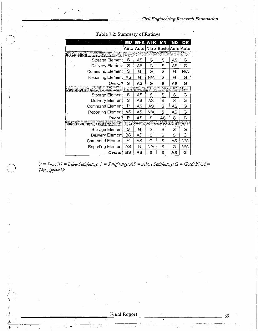
()
,j'
.~.",I.-"
Civil Engineering Research Foundadon
Table 7.2: Summary of Ratings
Auto Auto Nitro Basic Auto Auto
Ifr~J~II~ti~:n,i~1;~1}Eil~~r0.f;~~§~;fi,~J}tF"'--'-,..:-..:.....c..-T----:...~:...-;.:"-'T=_'_r'~__.:jStorage Element S AS G S AS G
. Delivery Elemen S' AS G S AS GCommand Element S G G S G N/A
Reporting Elemen AS G N/A S G G
Overal S AS G S AS G
:'p.~.r~KQHfl~~~t;1&~~~1i~;ilt..~~~~~~~~~~~~ill
P = Poor; BS = Below Satiifactory, S = Satiifactory;AS = Above Satisfactory; G = Good; N/A =Not Applicable
________________.=.F.=;in:.::a=I:...:R:.:.e:::Jpc;.;o:.:t:.:.t---- 69
.._-_ ... _._---
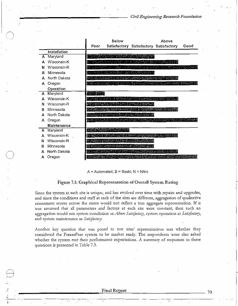
Civil Engineering Research Foundation
(l'-...._~j
InstallationA Maryland
A Wisconsin-K
N Wisconsin-R
B Minnesota
A North Dakota
A OregonOperation
A Maryland
A Wisconsin-K
N Wisconsin-R
B MinnesotaA North Dakota
A OregonMaintenance
A Maryland
A Wisconsin-K
N Wisconsin-R
B Minnesota
(J A North Dakota
A Oregon
Below AbovePoor Satisfactory Satisfactory Satisfactory Good
, , • ~'f "',' _ .' h --:. '_I', • '. 1,.' • or r • :~
• ". • , -' ' '.' , , ~ I " _, • - : :' I ~'I ~ ,".':
A.. r----..."
A =Automated; B =Basic; N =Nitro
Figure 7.1: Graphical Representation of Overall System Rating
Since the system at each site is unique, and has evolved over time with repairs and upgrades,and since the conditions and staff at each of the sites are different, aggregation of qualitativeassessment scores across the states would not reflect a true aggregate representation. If itwas assumed that all parameters and factors at each site were constant, then such anaggregation would rate system installation as Abo/Ie Sati.rfactory, system operation at Sati.gacto1Jl,and system maintenance as Sati.rfactory.
Another key question that was posed to test sites' representatives was whether theyconsidered tile FreezeFree system to be market ready. The respondents were also askedwhether the system met their performance expectations. A summary of responses to thesequestions is presented in Table 7.3.
Final Report 70
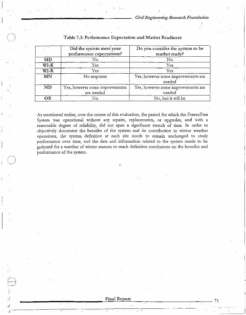
n"'~ .._.~
o
.i.....
Civil E.ngineering Research Foundation
Table 7.3: Performance Expectation and Market Readiness
Did the system meet·your Do you consider the system to beperformance expectations? market ready?
MD No NoWI-K Yes YesWI-R Yes YesMN No response Yes, however some improvements are _
neededND Yes, however some improvements Yes, however some improvements are
are needed neededOR No No, but it will be
As mentioned earlier, over the course of this evaluation, the period for which the FreezeFreeSystem was operational without any repairs, replacements, or upgrades, and with areasonable degree of reliability, did not span a significant stretch of time. In order toobjectively document the benefits of the system and its contribution to winter weatheroperations, the system definition at each site needs to remain unchanged to studyperformance over time, and the data and information related to the system needs to begathered for a number of winter seasons to reach definitive conclusions on the benefits andperformance of the system.
Final Report
-----------
71

o
o
o.r
,.r
.';'"
.,-1"!,1
__________..... ---- Civil Engineering Research Foundadon
APPENDICES
A. Selected Shop Drawings - FreezeFree System (Typical)B. Data Analysis (North Dakota)
______________-.-;F;:...i-n-a-lR---'ep'-o:....rt-=-- 72
.-::---._-_.. - --'-'
Civil Engineering Research Foundad,!n
n'--. .. /
Appendix-A
Selected Shop Drawings - FreezeFree System (Typical)·
o
;·i.~
-.<
_______________....:F:..:l=·o=a;:..l::,:R:.:;.cpJ:.0::.:rt:..:- 73
-;-_it,-.-=-.. _ .._--
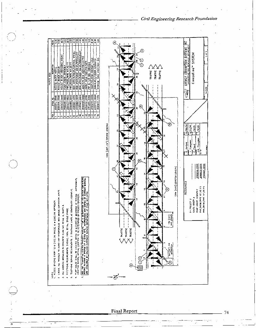
Civil Engineering Research Foundadon
~.
IIIII
~ ~ ~r. l: ~
\j'\lv
r' ~~~ .3=
"'Ji,. ! ...t:· .,: .~
~i!~ ~ !S",'
~~ "' H ~e:.
r:: :.~.~ ;i e"~a ~ g ~~;;~
.; '-
~'L;L."
C
~ nr.:~
~. ~~!;:; P ilL
!: ':< ;:> :U~ " ~..
;:: ~... t.r.
'II: ~ ! ~,~~... -~al:J
~. "E ...:~
-1(, '" ::: .::..t'
:-f
~II :;:
~,,~ ':j t:
~0: ll~ {~~~ 0{
U 8 r "~i3 ;r .., " t, ~
" ~ ~ ~ ~ J~ ~G~
~, § ~
II.f' [olf.:.,.C. ~~.' po~.~. (: "" ..
~.,t,. :loll .
~0< ~ ~ ~~ !~H
toE e :r ~ ~~ ·rE., !' '" ~. ~ I:S ...~
~ ~ :;l~, c: :J "u ;' ~,. -r. 1 .',I)
& ".. ~ ..?§~
Ii:' .. J, , ~i[, ~ .; " ~ ~ ~";l
3 .~ ,,~ ~->... f:' 7- §:: • ,r' 15"'g " ~~ ~ ... ~I~ 11 ~ ::",:t t:' C:i X
9_· n .." ~ <' '" "J
I~"-./
C)
Final Report 74
-.~-,--"'"
-----------------------------
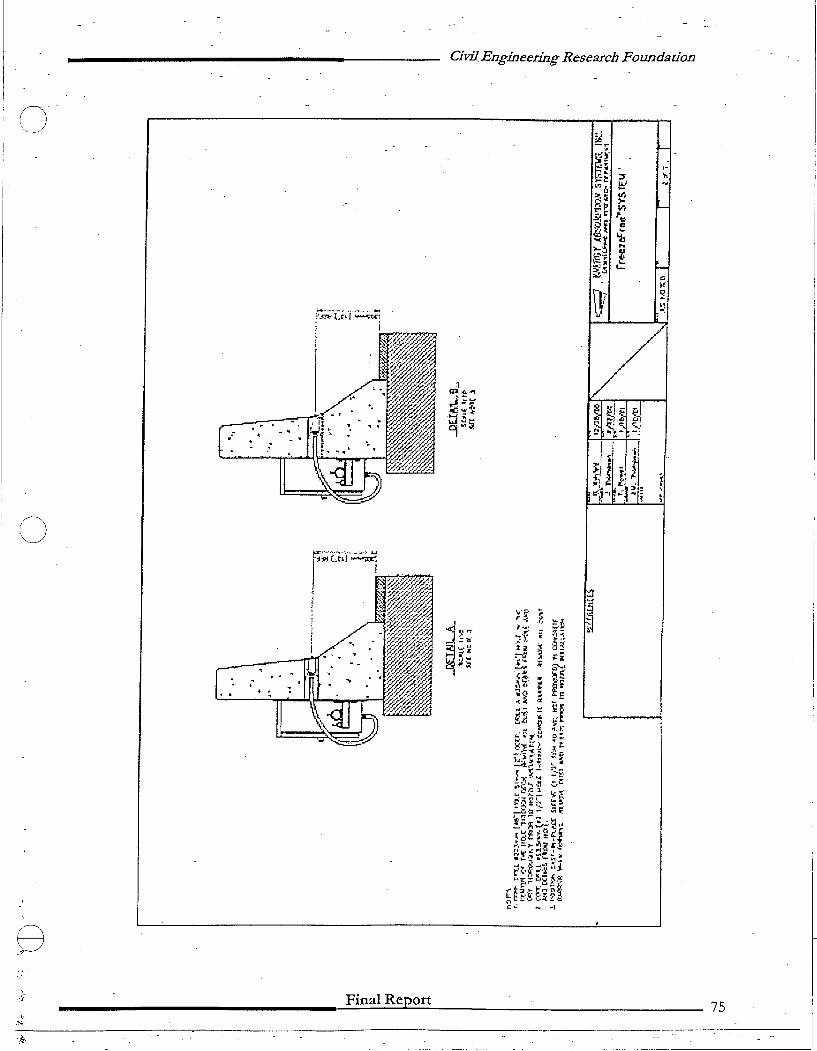
Civil. Engineering Research Foundadon
o
eFinal Report 75
._---------------_.~._-_ .._-----,- .._._-_._---------

Ci,iJ Engineering Research Foundadon
~ § ~j ~::! c:;;1 - "').:lr
'-!'-'I
,i91
~~~I ....
~I •..J ..J ~ " I:: !
tI ~ ~.~-:i :~
I-:t-' ~ •~o.-,
&
I
EH~ ~~
.I,
.}j' , t. ~,
I ""I"'. -:'~:;; ~I~.~,;:"i
~If,
i;to, ,~\
~. -.~I
~~ i;-'\
t'! r ~ :;;.toI~! _ ...,~. j ih'
~ - ~, to: '. '~IJ· -. h-' ~'
1. ~ ~ !to ~ ~"" ~~~.~jl.~
c. :.: r ~. t
r.
-~-.....
8
o
0 ~-'i
~H'--l..: :st:~ '.320
~,~ IiVJ7.:: rr.::l> V1
~. ~
10.1\. ;-; ~ ...g, III...
u L' --=~ Lt{J
>-!:. (!~ ~ ~ ~~ ...
"'f ..::!5~
Final Report 76
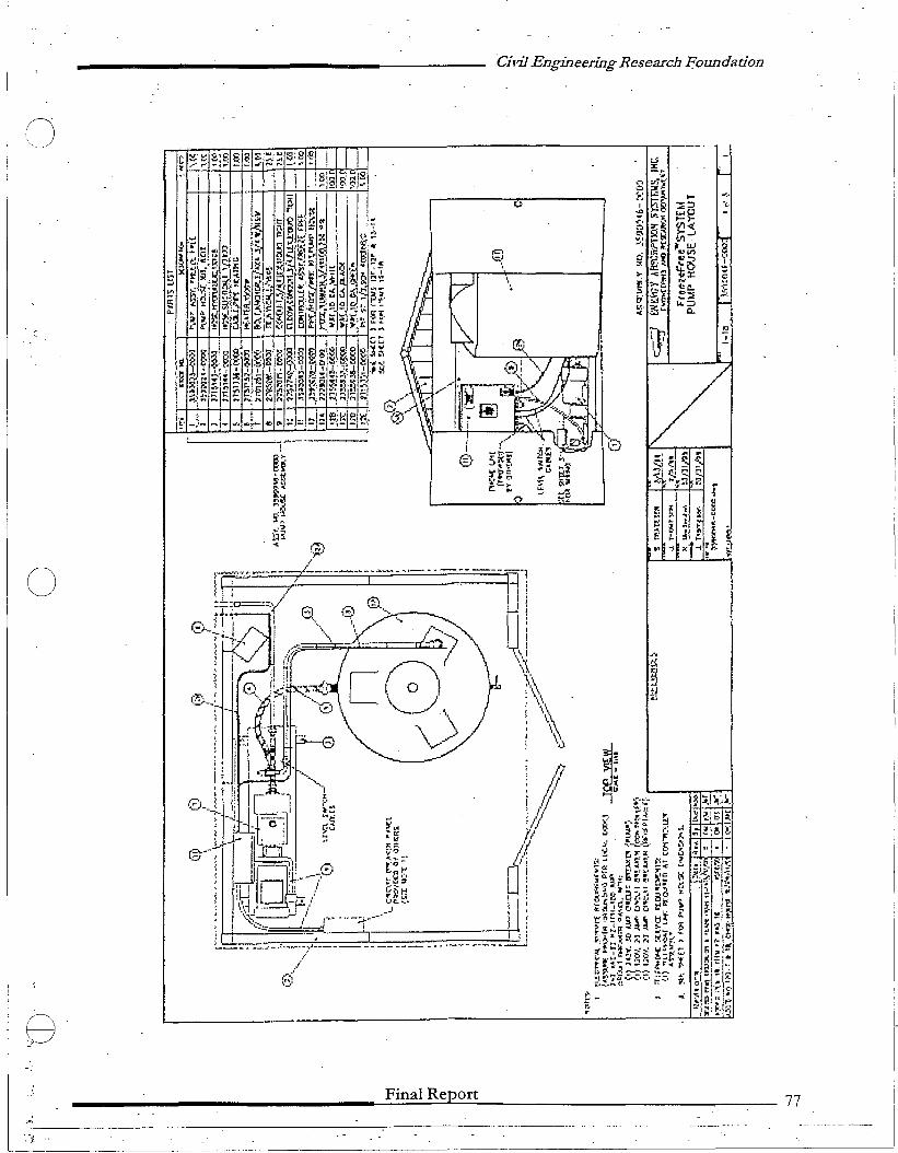
Civil Engineering Research £oundation
I-j
L-
..... ~,
:;::;, ·c·
~~
~5 'B"~ W."1)~~3'tJ:
~c..:::;.,.
~~ $~
"'~ -,CL I
.,,Ti71. ~..LJ
o
8Final Report 77
--J. ( .-
o
o
8
....
CivilEnginee~JngResearch Foundadon
Appendix-B
Data Analysis (North Dakota)
________---------=-F:::in:::a:.:.l.::.R.:.:e:..&:p....:.o.::.rt=--~-----------__:_--78
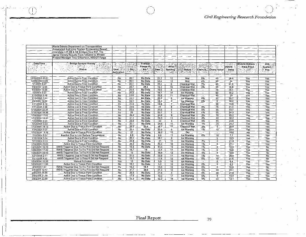
'.," ~-.- Q)
North Dakota Department on TransportationI ,Automated Anti icing System Evalauation Report
Interstate 1-29 NB & SB Bridges Near R.P.114Sprav Historv Results From 12125103 to 4111104Proiect Manager Troy Gilbertson, NDDOT Fargo
o I)~'
Civil Engineering Research Foundation
I'
<~~,~,e,!~.me ,;. ~;. ."...... ,
; .
Bridge-.'~; " ._~.
..:,~:,.;-:.. ::}~Y;r~t~,;\1jr.1·•.:".; ......
'j
II
12/25/2003 20:01 I Active Due to Frost Condition12/26/20030:00 I Active Due 10 Frosl Condition
1/1/2004 9:37 I Aclive Due 10 Frosl Condition1/2/200412:58 I AClive Due 10 Freeze Point Condition112/2004 10:38 I Active Due 10 Freeze Point Condition11212004 9:07 I Active Due 10 Frost Condition
1/10/20048:46 I Active Due 10 Frosl Condition1/10/20044:44 I Active Due 10 Frosl Condition1/9/2004 19:52 I Active Due 10 Frosl Condition1/11/20046:40 I Aclive Due to Frosl Condition1/11/20042:39 I Active Due to Frost Condilion
1/10/200422:37 I Aclive Due 10 Frosl Condition1/10/200418:36 I Aclive Due to Frost Condition1/1012004 17:01 I Active Due 10 Frosl Condition1/12/200415:34 I Active Due to Frost Condition1/12/2004 9:24 I Active Due to Frost Condition1112/2004 5:23 I Active Due to Frost Condition
1/12/200419:13 I Active Due to Freeze Point Condilion1/14/20040:37 I Aclive Due to Frosl Condition1115/200413:16 I Aclive Due to Freeze Point Condilion1/15/20046:37 I Inaclive Due to Low Surface Temperalure1/16/20045:14 I Active Due 10 Frost Condition1/17/20040:13 I Aclive Due 10 Frost Condition
1/16/200420:05 I Active Due to Freeze Poinl Condition1/20/200416:10 RWIS Triggered Due To Frz PI & Did Not Respond1120/2004 17:32 RWIS Triggered Due To Frz Pt & Did Not Respond1/20/200420:10 I RWIS Trig.9.ered Due To Frz PI & Did Nol Respond1/21/20040:11 I RWIS Triggered Due to Frosl & Did Not Respond1/21/20044:32 I RWIS Triggered Due to Frost & Did Nol Respond
1/26/2004 10:20 I Manual Activation1/26/2004 11 :56 I Aclive Due to Freeze Point Condition2/5/2004 1:51 I RWIS Triggered Due To Frz Pt & Did Nol Respond2/5/200412:47 I RWIS Triggered Due To Frz Pt & Did Nol Respond2/5/200416:56 I Active Due to Freeze Poinl Condition2/5/2004 21 :30 I Active Due 10 Freeze Poinl Condition2/5/2004 22:50 I Active Due 10 Freeze Point Condition
NoNoNoNoNoNoNoNoNoNoNoNoNoNoNoNoNoNoNoNoNoNoNoNoNoNoNoNoNoYesNoNoNoNoNoNo
26.133.120.125.724.420.322.620.120.121.622.623.525
26.431.123.920.125.220.1276.6
20.122.828.216.916.718
22.618.710
15.115.331.125.517.816.3
No DataNo DataNo Data
29.3No DataNo DalaNo DataNo DataNo DataNo DataNo DataNo DataNo DataNo DataNo DataNo DataNo Data
23.4No DataNo DataNo DataNo DataNo DataNo DataNo Data-1-4-
No DataNo DataNo DalaNo DataNo Data
18.330.9
No DataNo DataNo Data
27.733.419.416.219.618.722.820.318.319.821
23.523.724.629.323
24.618.122.516.26.818.721
26.413.515.418.925.917.65.95.916.521.421.613.512.2
1213915
1411847
7
114111761311
1110161413111210161612
1716
WeiWet
Chemical WetChemical WetChemical WetIce Warning
Chemical WetIce WarninQIce Warning
Chemical WetChemical WetChemical WetChemical WetChemical WetChemical WetChemical WetIce Warning
Chemical WetIce Warning
DryIce WarningIce WarningIce WarningIce WarningIce Warning.Ice WarningIce WarningIce WarningIce WarningIce WarningIce WarningIce WarningIce WarningIce WarningIce WarningIce Warning
5%4%7%3%
0%0%
5%5%4%3%4%5%1%3%1%
0%
2%1%1%1%1%1%0%
0%0%0%0%0%0%
859595957560953059575555570459520515
1055555515155552030530
28.934
21.916.920.119.223
20.719.419.921.423.724.325.230.223.925.220.822.819.67.719.921.9'27.114.915:619.626.821.66.46.316.922.121.914.413.1
YesYesYesYesYesYesYesYesYesYesYesYesYesYesYesYesYesYesYesNoNo
YesYesYesYesYesYesYesYesYesYesYesYesYesYesYes
YesYesYesYesYesYesYesYesYesYesYesYesYesYesYesYesYesYesYesYesYesYesYesYesNoNoNoNoNoYesYesNoNoYesYesYes
Final Report 79
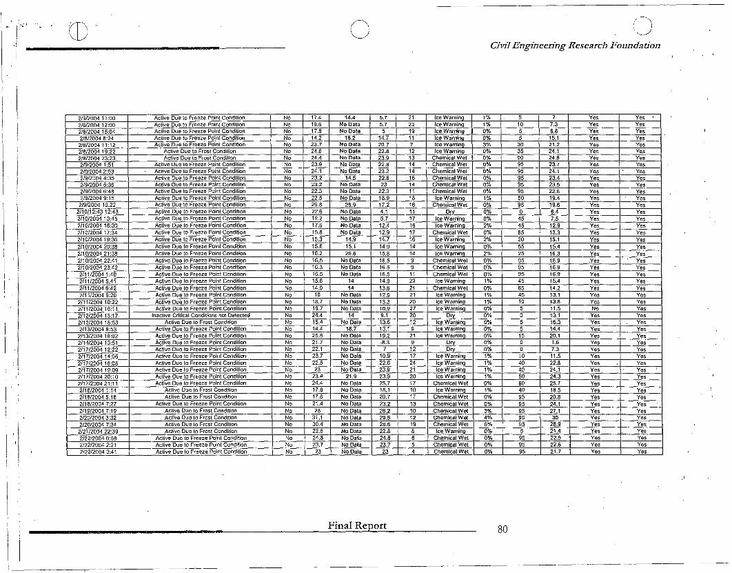
(I)"" .1'"''-------o CJ
Civil Engineering Research Foundation
,II
2/612004 11 :00 Active Due to Freeze Point Condition No 17.4 14.4 5.7 21 Ice Warnina 1% 5 7 Yes Yes ,2/6/2004 12:00 Active Due to Freeze Point Condition No 19.6 No Data 5.7 23 Ice WarninQ 1% 10 7.3 Yes Yes2/6/2004 15:04 Active Due to Freeze Point Condition No 17.8 No Data 5 19 Ice Warnina 0% 5 6.8 Yes Yes2/8/2004 8:24 Active Due to Freeze Point Condition No 14.2 16.2 14.7 11 Ice Warnina 0% 5 15.1 Yes Yes2/8/2004 11:12 Active Due to Freeze Point Condition No 23.7 No Data 20.7 7 Ice Warnina 3% 30 21.2 Yes Yes2/8/2004 19:22 Active Due to Frost Condition No 24.6 No Data 22.8 12 Ice Warnina 0% 35 24.1 Yes Yes2/8/2004 23:23 Active Due to Frost Condition No 24.4 No Data 23.9 13 Chemical Wet 0% 90 24.8 Yes Yes2/9/2004 1:51 Active Due to Freeze Point Condition No 23.9 No Data 22.8 14 Chemical Wet 0% 95 23.7 Yes Yes2/9/2004 2:53 Active Due to Freeze Point Condition No 24.1 No Data 23.2 14 Chemical Wet 0% 95 24.1 Yes Yes2/9/2004 4:35 Active Due to Freeze Point Condition No 23.2 14.5 22.6 16 Chemical Wet 0% 95 23.4 Yes Yes2/9/2004 5:36 Active Due to Freeze Point Condilion No 23.2 No Data 23 14 Chemical Wet 0% 95 23.5 Yes Yes2/9/2004 6:48 Active Due 10 Freeze Point Condition No 22.3 No Data 22.3 11 Chemical Wet 0% 95 22.6 Yes Yes2/9/2004 9:15 Active Due to Freeze Point Condition No 22.5 No Data 18.9 18 Ice Warning 1% 50 19.4 Yes Yes
2/9/2004 10:22 Active Due to Freeze Point Condition No 26.8 28.9 17.2 16 Chemical Wet 0% 95 19.6 Yes Yes2/10/12:4312:43 Active Due to Freeze Point Condition No 22.6 No Data 4.1 11 Drv 0% 0 6.4 Yes Yes2/10/2004 13:45 Active Due 10 Freeze Point Condition No 19.2 No Data 5.7 17 Ice Warnina 0% 45 7.5 Yes Yes2/10/2004 16:30 Active Due to Freeze Point Condition No 17.6 No Data 12.4 16 Ice Warning 2% 45 12.9 Yes Yes2/10/200417:34 Active Due to Freeze Point Condition No 15.8 No Data 12.9 17 Chemical Wet 0% 65 13.3 Yes Yes2/101200419:36 Active Due to Freeze Point Condition No 15.3 14.9 14.7 16 Ice Warning 2% 20 15.1 Yes Yes2/10/2004 20:38 Active Due to Freeze Point Condition No 15.6 15.1 14.9 14 Ice Warning 0% 55 15.4 Yes Yes2/10/200421:38 Active Due to Freeze Point Condition No 16.2 26.6 15.8 14 Ice Warning 2% 25 16.3 Yes Yes2/10/2004 22:41 Active Due to Freeze Point Conditian No 16.5 No Data 16.5 9 Chemical Wet 0% 95 16.9 Yes Yes2/10/2004 23:42 Active Due to Freeze Point Condition No 16.3 No Data 16.5 9 Chemical Wet 0% 95 16.9 Yes Yes2/11/2004 1:40 Active Due to Freeze Point Condilien No 16.5 No Data 16.5 11 Chemical Wet 0% 95 16.9 Yes Yes2/11/2004 5:41 Active Due to Freeze Point Condition No 15.6 14 14.9 22 Ice Warning 1% 45 15.4 Yes Yes2/1112004 6:42 Active Due to Freeze Point Condition No 14.9 14 13.6 21 Chemical Wet 0% 65 14.2 Yes Yes2/11/2004 9:20 Active Due to Freeze Point Condition No 16 No Data 12.9 21 Ice Warning 1% 45 13.1 Yes Yes
2/1112004 10:22 Active Due to Freeze Point Condition No 18.7 No Data 13.3 20 Ice Warning 1% 10 13.8 Yes Yes2/1112004 16:11 Active Due to Freeze Poinl.Condilion No 18.7 No Data 10.9 27 Ice Warnina 0% 5 11.5 No Yes2/12/200413:17 Inactive Critical Conditions not Detected No 24.4 14 9.1 20 Drv 0% 0 13.1 Yes Yes2/12/2004 18:53 Active Due to Frost Condition No 15.4 No Data 13.6 12 Ice Warning 0% 5 16.3 Yes Yes2/13/2004 8:53 Active Due to Freeze Point Condition No 14.4 18.7 13.1 9 Ice Warnina 0% 5 14.4 Yes Yes
2/13/2004 18:02 Active Due to Freeze Point Condition No 25.5 No Data 19.2 21 Ice Warnina 0% 15 20.1 Yes Yes2/14/2004 13:51 Active Due to Freeze Point Condition No 21.7 No Data -8.3 9 Drv 0% 0 1.6 Yes Yes2/17/200412:22 Active Due to Freeze Point Condition No 22.1 No Data 7 12 Drv 0% 0 7.3 Yes Yes2/17/2004 14:06 Active Due to Freeze Poinl Condition No 23.7 No Dara 10.9 17 Ice Warnina 1% 10 11.5 Yes Yes2/17/200418:08 Active Due to Freeze Point Condition No 22.5 No Data 22.6 24 Ice WarninQ 1% 40 22.8 Yes Yes2/17/2004 19:09 Active Due to Freeze Point Condition No 23 No Data 23.9 21 Ice Warning 1% 40 24.1 Yes Yes
,2/17/200420:10 Active Due to Freeze Point Condition No 23.4 21.9 23.9 20 Ice Warnina 1% 50 24.3 Yes Yes2/17/2004 21 :11 Active Due to Freeze Point Condition No 24.4 No Data 25.7 17 Chemical Wet 0% 60 25.7 Yes Yes2/18/2004 1:14 Active Due to Frost Condition No 17.8 No Data 18.1 10 Ice Warning 1% 40 18.5 Yes Yes2/18/20045:18 Active Due to Frost Condilion No 17.8 No Data 20.7 17 Chemical Wet 0% 95 20.8 Yes Yes2/18/2004 7:27 Active Due to Freeze Point Condition No 21.4 No Data 23.2 13 Chemical Wet 0% 95 24.1 Yes Yes2/19/20047:19 Active Due to Frost Condition No 28 No Data 26.2 10 Chemical Wet 3% 95 27.1 Yes Yes2/20/2004 3:32 Active Due to Frost Condition No 31.1 No Data 29.5 12 Chemical Wet 4% 95 30 Yes Yes2/20/2004 7:34 Active Due to Frost Condition No 30.4 No Data 28.6 19 Chemical Wet 6% 95 28.9 Yes Yes
2/21/200422:39 Active Due to Frost Condition No 22.8 No Data 22.8 8 Ice Warnina 0% 5 '21.4 Yes Yes212212004 0:58 Active Due to Freeze Point Condition No 24.8 No Data 24.8 6 Chemical Wet 0% 95 22.5 Yes Yes2/22/20042:21 Active Due to Freeze Point Condition No 23.7 No Data 23.7 5 Chemicat Wet 0% 95 22.6 Yes Yes2/22/2004 3:41 Active Due to Freeze Point Condition No 23 No Data 23 4 Chemical Wet 0% 95 21.7 Yes Yes
Final Report 80
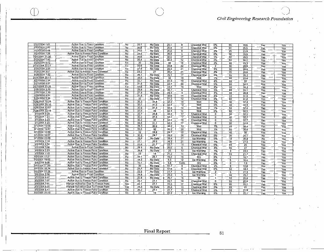
CD o oCil'iJ Engineering Researcb Foundation
:
i
2/22/2004 7:41 Active Due to Frost Condition No 20.1 No Data 20.1 8 Chemical Wet 0% 95 19.6 Ves Ves ,2/23/2004 2:46 Active Due to Frost Condition No 26.8 No Data 26.8 11 Chemical Wet 3% 90 25.5 Ves Ves2/23/2004 6:48 Active Due to Frost Condition No 26.6 No Dala 26.6 8 Chemical Wet 3% 95 25.9 'Ves Ves2/24/2004 7:39 Active Due 10 Freeze Point Condition No 28.8 No Dala 28.8 6 Chemical WeI 0% 90 25.9 Ves Ves
2/24/2004 21 :38 Active Due to Frost Condition No 30.6 No Data 30.6 17 Chemical WeI 1% 60 29.5 Ves Ves2/25/2004 1:40 Active Due to Frost Condition No 30.4 No Data 30.4 12 Chemical Wei 2% 60 30.2 Ves Ves2/25/2004 5:42 Active Due to Frost Condition No 30 No Data 30 18 Chemical Wet 3% 95 29.3 Ves Ves
2/25/2004 22:51 Active Due to Frost Condition No 30.6 No Data 28.8 22 Chemical Wet 2 50 29.8 Ves Ves2/26/2004 2:50 Active Due to Frost Condition No 27.9 No Data 28.2 21 Chemical Wet 3% 50 28.8 Ves Ves212612004 3:51 Active Due to Freeze Point Condition No 28.2 27 28.2 21 Chemical Wet 4% 95 28.6 Ves Ves2/26/2004 7:52 Active Due to Frost Condition No 26.1 No Data 26.1 17 Chemical Wet 5% 95 26.2 Ves Ves
2/26/2004 20:11 Active Due to Frost Condition No 33.6 No Dala 32 19 WeI 1% 95 33.4 Ves Ves2/27/20040:34 Active Due to Frost Condition" No 30.7 No Data 31.3 19 Chemical WeI 4% 95 32 Ves Ves2/27/20044:57 Active Due to Frost Condition No 31.8 No Data 32.7 25 Chemical Wet 6% 95 34.2 Ves Ves
2/27/200423:28 Active Due to Frost Condition No 33.6 No Data 33.4 16 Wet 4% 90 34.3 Ves Ves2/28/2004 3:29 Active Due 10 Frost Condition No 29.8 No Data 30.7 8 Chemical Wet 5% 95 31.1 Ves Ves2/28/2004 7:30 Active Due to Frost Condition' No 27.9 No Data 26.4 4 Chemical Wet 4% 95 26.8 Ves Ves2/29/20044:54 Active Due to Frost Condition No 31.8 No Dala 30.6 14 Chemical Wet 3% 95 31.5 Ves Ves2/29/2004 9:39 Active Due to Frost Condition No 32 No Data 31.3 12 Chemical WeI 5% 95 31.8 Ves Ves2/29/2004 18:39 Active Due to Freeze Point Condition No 33.3 31.8 32.2 14 Wet 1% 30 32.4 Ves Ves2/29/200420:10 Active Due to Freeze Point Condition No 33.1 31.5 32.4 13 Wet 0% 45 32.5 Ves Ves2/29/2004 22:07 Active Due to Freeze Point Condition No 32.9 31.3 32.4 14 WeI 1% 55 32.4 Ves Ves2/29/2004 23:19 Active Due to Freeze Point Condition No 32.9 32 32.4 14 Wet 0% 85 32.5 Ves Ves
3/1/2004 0:20 Active Due to Freeze Point Condition No 32.7 31.8 32.4 17 Chemical Wet 0 50 32.5 Ves Ves3/112004 1:21 Active Due to Freeze Point Condition No 32.2 31.5 32.4 17 Chemical Wet 0 40 32.7 Ves Ves3/1/2004 2:23 Active Due to Freeze Point Condition No 32.2 32 32.4 19 Chemical Wet 0 10 32.7 Ves Ves3/1/20043:23 AClive Due to Freeze Point Condition No 32.5 31.1 32.4 17 Chemical WeI 0 50 32.5 Ves Ves3/1/2004 13:56 Active Due to Freeze Point Condition No 34.3 30.9 30.2 19 WeI 1% 45 30.4 Ves Ves3/1/200415:57 Active Due to Freeze Point Condilion No 33.6 32 30.2 22 Wet 1% 60 30.4 Ves Ves3/1/2004 16:59 Active Due to Freeze Point Condition No 32 31.6 29.7 22 Chemical Wet 1% 40 30 Ves Ves3/1/2004 18:07 . Active Due to Freeze Point Condition No 30.9 29.7 28.9 26 Chemical Wet 0% 30 29.1 No Ves3/1/200422:08 Active Due to Frost Condition No 28.9 No Dala 28.4 27 Ice Warnina 0% 15 28.8 No Ves3/2/2004 2:19 Active Due 10 Freeze Point Condition No 27.1 25.5 26.2 21 Ice Warnina 1% 30 27.5 Ves Ves3/2/20044:50 Active Due to Freeze Point Condition No 23.4 21.7 23.7 15 Chemical Wet 0% 95 25 Ves Ves3/3/2004 3:08 Active Due to Frost Condition No 28.6 No Dala 26.6 6 Chemical Wet 3% 95 27 Ves Ves3/3/2004 5:53 Active Due to Freeze Point Condition No 26.8 No Data 23 12 'Ice Warnina 1% 5 23.5 Ves Ves3/3/20047:15 Active Due to Freeze Point Condition No 25 14 21.2 11 Chemical Wet 0% 95 21.7 Ves Ves
3/3/2004 17:21 Active Due to Freeze Point Condition No 29.1 29.1 16.2 15 DrY 0% 5 16.7 Ves Ves3/3/2004 19:00 Active Due to Freeze Point Condition No 18.3 No Data 9.3 12 Ice Warnina 0% 5 10.4 Ves Ves3/4/2004 9:08 Aclive Due to Freeze Point Condition No 15.1 No Data 6.8 Calm Drv 0% 0 7.9 Ves Ves
3/4/2004 11 :09 Active Due to Freeze Point Condition No 30 No Data 11.7 9 Chemical Wet 1% 5 12.6 Ves Ves3/4/200418:24 Active Due 10 Freeze Point Condition No 24.4 No Dala 17.6 6 Chemical Wet 0% 55 19.4 Ves Ves3/4/2004 22:26 Active Due to Frost Condition No 23.5 No Data 21.7 8 Ice Warnino 2 5 22.3 Ves Ves3/5/2004 2:28 Aclive Due to Frost Condition No 24.8 No Data 25.3 6 Ice Warnina- 1 35 25.7 Ves Ves3/5/2004 6:07 Active Due to Freeze Point Condition No 22.8 No Dala 20.7 16 16 1 55 20.8 Ves Ves3/5/2004 7:37 Active Due to Freeze Point Condition No 22.1 27.1 20.1 19 Chemical Wet 0 95 20.5 Ves Ves3/5/2004 7:51 Manual Activation Due To Freeze Point Ves 22.1 27.1 20.3 17 Chemical Wet 0% 95 20.7 Ves Ves3/5/2004 8:35 Manual Acfrvation Due To Freeze Point Ves 24.3 No Data 20.8 16 Chemical WeI 0% 95 21 Ves Ves3/5/2004 9:41 Active Due to Freeze Point Condition No 26.2 27.1 21.7 16 Chemical Wet 0% 95 21.9 Ves Ves
3/5/200522:15 Active Due to Freeze Point Condilian No 27 14 21.2 6 Ice Warnina 0% 5 22.1 Ves Ves
Final Report 81
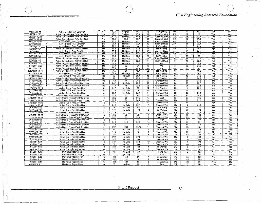
Ir
1) o (~')
I,~
Civil Engineering Research Foundation
I
!r
3/6/2004 6:39 Active Due to Frost Condition No 16.3 No Data 14.5 11 Ice WarninQ 0% 35 15.1 Yes Yes3/6/2004 7:41 Active Due to Freeze Point Condition No 18.7 No Data 15.6 11 Chemical Wet 0% 95 16 Yes Yes3/6/2004 10:06 Active Due 10 Freeze Point Condition No 30.4 No Data 19,8 17 Chemical Wet 1% 45 20.3 Yes Yes3/6/2004 19:36 Active Due to Freeze Point Condition No 31.5 29.8 29.7 19 Chemical Wet 2% 85 31.8 Ves Yes3/6/2004 23:37 Active Due to Frost Condilion No 26.1 No Dala 25.7 17 Chemical Wet 0% 70 20.8 Ves Ves3/7/2004 3:39 Active Due to Frost Condition No 28.9 No Dala 27.7 16 Chemical Wet 2% 95 29.8 Ves Ves3/7/2004 7:41 Active Due to Frost Condition No 28.2 No Data 27 18 Ice Wamino 1% 35 27.7 Ves Ves3/8/2004 0:51 Active Due to Freeze Point Condition No 19.9 No Data 13.6 9 Ice Warnino 0% 5 14.2 Ves Yes3/8/2004 4:53 Active Due to Frost Condition No 23.5 No Data 21.7 16 Chemical Wet 0% 95 24.3 Ves Ves3/8/2004 22:41 Active Due to Frost Condilion No 32.4 No Data 30.9 10 Chemical Wei 0% 5 33.3 Ves Ves3/9/2004 2:42 Active Due to Frost Condition No 27.3 No Data 27.1 11 Ice Warnino 1% 30 28 Ves Ves3/9/2004 6:12 Active Due to Freeze Point Condition No 23.7 No Dala 22.3 9 Chemical Wei 0 65 22.6 Ves Ves3/9/20047:18 Active Due to Freeze Point Condilion No 24.3 No Data 22.6 9 Chemical Wet 0 75 23.2 Ves Yes3/10/2004 3:05 Active Due to Freeze Point Condition , No 33.8 No Data 33.3 15 Wet 2 10 35.1 Ves Ves3/10/2004 7:52 Active Due to Freeze Point Condition No 33.4 32 34 17 Wet 3 95 34.5 Ves Ves
3/1012004 17:47 AClive Due to Freeze Point Condition No 33.6 32 24.1 22 Wet 0% 65 25 Ves Yes3/10/2004 19:40 Active Due to Freeze Point Condition No 20.5 21 10.4 28 Ice Warnino 0% 5 10.9 No Ves3/13/2004 0:22 Active Due to Frost Condition No 30.6 No Data 28.8 13 Ice Warnino 0% 5 30.4 Ves Ves3/13/2004 5:22 Active Due to Frost Condition No 30 No Data 28.4 18 Ice Warnino 0% 10 31.3 Ves Ves
3/13/2004 23:46 Active Due to Freeze Point Condition No 27 14 23.9 16 Ice Warnino 0% 10 24.1 Ves Ves3/14/20042:12 Active Due to Freeze Point Condition No 25.7 14 24.3 27 Chemical Wet 0% 55 24.6 No Ves3/14120044:13 Active Due 10 Freeze Point Condition No 24.3 No Data 23.2 29 Chemical Wet 0% 95 23.5 No Yes3/14/2004 5:22 Active Due to Freeze Point Condition No 23.7 16 22.6 29 Chemical Wet 0% 95 22.8 No Ves3/15/2004 22: 15 Active Due to Frost Condition No 24.8 No Dala 23 12 Ice Warnino 0% 5 23.4 ' Yes Ves3/16/20042:16 Active Due to Frost Condition No 23.2 No Data 25 13 Chemical Wet 0% 95 25.9 Ves Ves3/16/20046:18 Active Due to Frost Condition No 26.6 No Data 26.8 14 Chemicat Wet 9% 95 27.3 Yes Ves
3/16/2004 12:38 Active Due 10 Freeze Point Condition No 32.2 32 30.4 15 Chemical Wet 4% 95 30.9 Ves Ves3/16/200413:41 Active Due to Freeze Point Condilian No 32.9 32 30.6 17 Wet 0% 95 30.9 Ves Yes3/16/200414:46 Active Due to Freeze Point Condition No 32.2 32 30.7 14 Chemical Wet 0% 95 31.1 Ves Ves3116/2004 19:05 Active Due to Frost Condition No 31.5 28 32 11 Chemical Wet 0% 65 32 Ves Ves3/16/2004 23:06 Active Due to Frost Condition No 24.4 No Data 24.1 7 Chemical Wet 5% 5 24.3 Ves Ves3/17/2004 3:19 Active Due to Frost Condition No 18 No Data 16.5 11 Ice Warnino 3% 40 17.1 Ves Ves3/1712004 7:20 Active Due to Frost Condition No 17.4 No Data 17.6 6 Ice Warnino 7% 50 17.8 Ves Yes
3/171200421:22 Active Due to Freeze Point Condition No 32.9 32 32 4 Wet 8% 30 32.4 Ves Yes3/17/2004 22:23 Active Due to Freeze Point Condition No 32.2 32 32 4 Chemical Wet 0% 55 32.5 Ves Yes3/1712004 23:24 Active Due to Freeze Point Condition No 32.5 32 32.4 5 Chemical Wet 0% 65 32.5 Ves Ves3/18/2004 0:26 Active Due to Freeze Point Condition No 33.1 32 32.2 9 Wet 0% 15 32.4 Ves Ves3/18/2004 1:27 Active Due to FreeZe Point Condition No 31.8 31.5 31.8 14 Chemical Wet 0% 70 32 Ves Yes3/18/2004 2:29 Aclive Due to Freeze Point Condition No 31.8 32 31.3 14 Chemical Wet 0% 95 31.5 Ves Yes3/18/2004 3:31 Active Due to Freeze Point Condition No 29.1 28.8 28.26 11 Chemical Wet 3% 95 28.4 Yes Ves
3/21/200422:07 Active Due to Frost Condition No 18.1 No Data 16.3 6 Ice Warnino 0% 5 17.8 Yes Yes3/22/2004 2:09 Active Due to Frost Condition No 14.9 No Data 18 8 Chemical Wet 0% 60 18.1 No Ves3/22/2004 6:10 Active Due to Frost Condition No 14.7 No Data 18.7 9 Chemical Wei 0% 95 18.9 No Ves3/23/2004 0:05 Active Due to Frosl Condition No 29.1 No Data 27.3 14 Chemical Wet 1% 5 28.6 Ves Ves4/112004 5:24 Active Due to Frost Condition No 32.2 No Data 30.6 11 Chemical Wet 0% 10 32.5 Ves Ves4/3/2004 1:32 Active Due to Frost Condition No 33.4 No Dala 31.8 12 Chemical Wet 0% 5 32.9 Ves Ves4/3/2004 5:33 Active Due to Frost Condition No 29.1 No Dala 30.4 5 Chemical Wet 2% 40 30.6 Ves Ves4/4/2004 1:45 Active Due to Frost Condition No 30.6 No Data 28.8 4 Ice Warnino 0% 5 30 Ves Ves4/4/20046:47 Active Due to Frost Condition No 27.5 No Data 28.9 4 Chemieal Wet 0% 80 29.1 Ves Ves4/8/2004 1:01 No Status Report Given No 32.7 No Data 31.3 11 Ice Warnino 0% 5 32.2 Ves No4/8/2004 6:01 No Status Report Given No 27.3 No Data 27.7 8 Frost 0% 0 28.9 Ves No4/9/2004 6:38 No Status Report Given No 31.6 32 27.1 4 Ice Warnino 0% 35 28.9 Ves No4/9/2004 7:40 No Status Report Given No 31.3 32 26.1 8 Ice Warnino 0% 45 28.9 Ves No4/9/2004 8:42 No Status Report Given No 31.5 32 25.5 8 Ice Warnino 0% 35 28.4 Yes No
4111/20045:21 No Status Report Given I No 22.1 No Data 22.8 9 Frost 0% 0 24.4 Ves No
r'
"\
Final Report 82