Evaluation of test methods used to characterize fiber...
7
General rights Copyright and moral rights for the publications made accessible in the public portal are retained by the authors and/or other copyright owners and it is a condition of accessing publications that users recognise and abide by the legal requirements associated with these rights. Users may download and print one copy of any publication from the public portal for the purpose of private study or research. You may not further distribute the material or use it for any profit-making activity or commercial gain You may freely distribute the URL identifying the publication in the public portal If you believe that this document breaches copyright please contact us providing details, and we will remove access to the work immediately and investigate your claim. Downloaded from orbit.dtu.dk on: Feb 15, 2019 Evaluation of test methods used to characterize fiber reinforced cementitious composites Paegle, Ieva; Fischer, Gregor Published in: Proceedings of the International Conference "Innovative Materials, Structures and Technologies" Publication date: 2013 Link back to DTU Orbit Citation (APA): Paegle, I., & Fischer, G. (2013). Evaluation of test methods used to characterize fiber reinforced cementitious composites. In Proceedings of the International Conference "Innovative Materials, Structures and Technologies" (pp. 122-128)
Transcript of Evaluation of test methods used to characterize fiber...

General rights Copyright and moral rights for the publications made accessible in the public portal are retained by the authors and/or other copyright owners and it is a condition of accessing publications that users recognise and abide by the legal requirements associated with these rights.
Users may download and print one copy of any publication from the public portal for the purpose of private study or research.
You may not further distribute the material or use it for any profit-making activity or commercial gain
You may freely distribute the URL identifying the publication in the public portal If you believe that this document breaches copyright please contact us providing details, and we will remove access to the work immediately and investigate your claim.
Downloaded from orbit.dtu.dk on: Feb 15, 2019
Evaluation of test methods used to characterize fiber reinforced cementitiouscomposites
Paegle, Ieva; Fischer, Gregor
Published in:Proceedings of the International Conference "Innovative Materials, Structures and Technologies"
Publication date:2013
Link back to DTU Orbit
Citation (APA):Paegle, I., & Fischer, G. (2013). Evaluation of test methods used to characterize fiber reinforced cementitiouscomposites. In Proceedings of the International Conference "Innovative Materials, Structures and Technologies"(pp. 122-128)
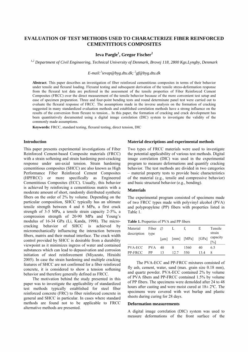
EVALUATION OF TEST METHODS USED TO CHARACTERIZE FIBER REINFORCED CEMENTITIOUS COMPOSITES
Ieva Paegle1, Gregor Fischer2 1,2 Department of Civil Engineering, Technical University of Denmark, Brovej 118, 2800 Kgs.Lyngby, Denmark
E-mail:[email protected]; [email protected]
Abstract. This paper describes an investigation of fiber reinforced cementitious composites in terms of their behavior under tensile and flexural loading. Flexural testing and subsequent derivation of the tensile stress-deformation response from the flexural test data are preferred in the assessment of the tensile properties of Fiber Reinforced Cement Composites (FRCC) over the direct measurement of the tensile behavior because of the more convenient test setup and ease of specimen preparation. Three and four-point bending tests and round determinate panel test were carried out to evaluate the flexural response of FRCC. The assumptions made in the inverse analysis on the formation of cracking suggested in many standardized evaluation methods and established correlation methods have a strong influence on the results of the conversion from flexure to tension... In this paper, the formation of cracking and crack development has been quantitatively documented using a digital image correlation (DIC) system to investigate the validity of the commonly made assumptions.
Keywords: FRCC, standard testing, flexural testing, direct tension, DIC
Introduction
This paper presents experimental investigations of Fiber Reinforced Cement-based Composite materials (FRCC) with a strain softening and strain hardening post-cracking response under uni-axial tension. Strain hardening cementitious composites (SHCC) are also known as High Performance Fiber Reinforced Cement Composites (HPFRCC) or more specifically as Engineered Cementitious Composites (ECC). Usually, this behavior is achieved by reinforcing a cementitious matrix with a moderate amount of short, randomly distributed synthetic fibers on the order of 2% by volume. Depending on the particular composition, SHCC typically has an ultimate tensile strength between 4 and 6 MPa, a first crack strength of 3-5 MPa, a tensile strain capacity 2-5%, a compression strength of 20-90 MPa and Young’s modulus of 16-34 GPa (Li, Kanda, 1998). The micro-cracking behavior of SHCC is achieved by micromechanically influencing the interaction between fibers, matrix and their mutual interface. The crack width control provided by SHCC is desirable from a durability viewpoint as it minimizes ingress of water and contained substances which can lead to depassivation and corrosion initiation of steel reinforcement (Miyazato, Hiraishi 2005). In case the strain hardening and multiple cracking features of SHCC are not confirmed for a fiber reinforced concrete, it is considered to show a tension softening behavior and therefore generally defined as FRCC.
The motivation behind the study presented in this paper was to investigate the applicability of standardized test methods typically established for steel fiber reinforced concrete (FRC) to fiber reinforced concrete in general and SHCC in particular. In cases where standard methods are found not to be applicable to FRCC alternative methods are presented.
Material descriptions and experimental methods
Two types of FRCC materials were used to investigate the potential applicability of various test methods. Digital image correlation (DIC) was used in the experimental program to measure deformations and quantify cracking behavior. The test methods are divided in two categories – material property tests to provide basic characteristics of the material (e.g., tensile and compressive behavior) and basic structural behavior (e.g., bending).
Materials
The experimental program consisted of specimens made of two FRCC types made with polyvinyl alcohol (PVA) and polypropylene (PP) fibers with properties listed in Table 1.
Table 1. Properties of PVA and PP fibers
Material description
Fiber type
[μm]
L [mm]
ft [MPa]
E [GPa]
Tensile strain capacity [%]
PVA-ECC PVA 40 8 1560 40 6.5 PP-FRCC PP 13 12.7 550 13.4 8
The PVA-ECC and PP-FRCC mixtures consisted of
fly ash, cement, water, sand (max. grain size 0.18 mm), and quartz powder. PVA-ECC contained 2% by volume of PVA fibers and PP-FRCC contained 1.5% by volume of PP fibers. The specimens were demolded after 24 to 48 hours after casting and were moist cured at 18± 2ºC. The specimens were covered with wet burlap and plastic sheets during curing for 28 days.
Deformation measurements
A digital image correlation (DIC) system was used to measure deformations of the front surface of the

specimens in the region of interest. Deformations of selected beams were additionally verified by an arrangement of LVDTs positioned on the back or sides of the specimens.
A commercially available DIC system called ARAMIS for three dimensional (3D) measurements and a single DSLR camera with 60 mm lens for two dimensional measurements were utilized to provide quantitative and qualitative information on the cracking behavior in the specimen. The 3D DIC system consists of two monochrome 4 mega pixel charged couple device (CCD) cameras and a data acquisition system which captures and processes images. The two CCD cameras were positioned at the same height and were focused on the same surface, but from different angles, allowing 3D deformation measurements. In order to facilitate DIC measurements adequate contrast in the grey-scale of individual objects is required. This was achieved by using black and white spray paint to apply a stochastic spatter pattern. A calibration was preformed prior to testing, using a calibration plate provided by the manufacturer, in order to insure accurate measurements.
The photogrammetry system tracks movements of small areas (called facets) of the specimen surface corresponding to 15 by 15 pixel square areas. Additional details on the DIC technique and equipment are available in the literature (Pease et.al. 2005).
Material properties
The basic material properties include compressive and tensile strength. Typically for cementations materials the tensile strength of concrete is given as a percentage of compressive strength or concrete gets tested in split cylinder test (e.g., ASTM C496, EN 12390-6). While the split cylinder test provides sufficient information for brittle materials in tension, where post-cracking tensile strength and deformations are negligible compared to cracking strength, significant post-cracking strength and deformations are evident in FRCC, requiring new test methods.
Single crack notched coupon test
The basic tensile material property for FRCC should be measured from a single crack. To isolate one crack and to avoid multiple, a new test method was developed (Fischer et.al. 2007, Pereira et al. 2010).
The tensile stress - crack opening response of PVA-ECC and PP-FRCC was determined using notched coupon specimens with a representative cross section of 8 mm 30 mm. The size of the notched coupon specimen and the test setup is shown in Fig. 1. The notch reduced the tested area of specimen by 60% to generate a single tensile crack in the specimen even for a strain hardening material. Deformation controlled tensile tests (0.3 mm/min loading rate) were conducted using clip-gauge measuring the opening displacement of a single crack. The deformation was applied to the specimen through hydraulic grips providing fixed support to the both ends of the specimen (Fischer et.al. 2007, Pereira et al. 2010).
Fig. 1. Single-crack notched coupon test: (a) specimen geometry; (b) test setup with clip gauges; (c) specimen after testing
Results
The obtained tensile stress - crack opening relationships for PVA-ECC and PP-FRCC are shown in Fig. 2. The average tensile strength taken from six test specimens for each material was 4.8 MPa and 3.0 MPa for PVA-ECC and PP-FRCC, respectively.
Fig. 2. Experimentally obtained tensile stress-crack opening relationships
The cracking strength of PP-FRCC is around the same as the maximum stress that fibers can bridge over the crack while cracking strength of PVA-ECC is smaller than the maximum stress than fibers can bridge over the crack. The property that the first cracking strength is lower than maximum stress that fibers can bridge over the crack results in a multiple cracking behavior under uni-axial tension in the SHCC material.
Tensile “dogbone” test
As the SHCC material can have multiple cracking, the single crack behavior does not completely characterize material response to uniaxial tension. Additionally to single crack stress – crack opening behavior, it is necessary to know the strain capacity, crack spacing, and the average, minimum and maximum crack widths at a specific strain level.

Fig. 3. Tensile “dogbone” test: (a) specimen geometry; (b) test setup; (c) part of specimen after testing
To determine experimentally the tensile stress-strain responses of PVA-ECC and PP-FRCC ‘dogbone’ specimens with a representative cross section of 25 mm 50 mm and with a representative length of 210 mm were used (Fig. 3). Similar to single crack notched coupon test, the deformation was applied to the specimen through hydraulic grips providing fixed support to both specimen ends. Deformation controlled tensile tests (0.5 mm/min loading rate) were conducted with linear variable differential transducers (LVDTs) measuring the tensile deformations and a DIC system measuring crack formations. The DIC equipment captured images of the representative section of the specimen at a rate of 1 Hz.
Fig. 4. Tensile properties of: (a) PVA-ECC and (b) PP-FRCC
Results
Typical tensile stress-strain relationships for PVA-ECC and PP-FRCC are shown in Fig. 4 (a) and (b), respectively. A strain hardening response for PVA-ECC was found (Fig. 4 a) while tension softening was seen for PP-FRCC (Fig. 4 b). The average first cracking strength taken from six test specimens was 4.1 MPa and 3.2 MPa for PVA-ECC and PP-FRCC, respectively. Average ultimate tensile strength for the PVA-ECC and PP-FRCC were 4.5 MPa and 4.1 MPa, respectively.
Compressive strength and modulus of elasticity
Compressive strength and modulus of elasticity of FRCC can be measured using standard methods for regular concrete using compressive cylinders or cubes (e.g., ISO 1920-10, EN 12390-3, ASTM C39). For this study compressive parameters were obtained using standard cylinders with a diameter of 100 mm and height of 200 mm. The specimens were loaded to failure in compression with a loading rate of 6.28 kN/s.
Results
The average compressive strength was 47.5 MPa and 39.0 MPa for PVA-ECC and PP-FRCC, respectively. The average elastic modulus in compression was 18.0 GPa in PVA-ECC and 13.6 GPa in PP-FRCC.
Structural behavior of FRCC
The most common structural behavior tests of FRC are bending tests – three and four point bending beam and round panel tests.
Three-point bending notched beam tests
The notched three-point bending test is a standard test method of FRC (e.g., EN 14651, RILEM TC-162 TDF, JCI-S-002-2003). For this study, 3 point bending tests were conducted according to RILEM TC-162 TDF. To investigate the effect of FRCCs specimens with different thickness, a modified three point bending notched beam with scaled geometry was tested. The geometry of the specimens has been shown in Fig. 5. Two different sizes of beams were tested:
1. L = 500 mm (span), h=b=150 mm; 2. L = 120 mm, h = b = 40 mm.
Fig. 5. Notched three point bending beam setup: (a) specimen geometry; (b) test setup with measuring devices.
Results
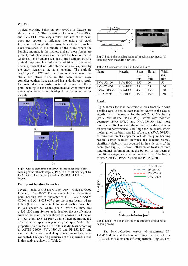
Typical cracking behaviors for FRCCs in flexure are shown in Fig. 6. The formation of cracks of PP-FRCC and PVA-ECC were very similar. The size of the beam does not appear to influence the nature of crack formation. Although the cross-section of the beam has been weakened in the middle of the beam where the bending moment is the highest and no shear forces are present, multiple cracking of material has been observed. As a result, the right and left side of the beam do not have a rigid response, but deform in addition to the notch opening, such that not all deformations are captured by the gage measuring the notch opening. The multiple cracking of SHCC and branching of cracks make the strain and stress fields in the beam much more complicated than those assumed in standards. As a result, the material characteristics obtained by notched three-point bending test are not representative when more than one single crack is originating from the notch or its vicinity.
Fig. 6. Cracks distribution of FRCC beams under three point bending at the ultimate stage: a) PVA-ECC of 40 mm height, b) PVA-ECC of 150 mm height and c) PP-FRCC of 150 mm height
Four point bending beam test
Several standards (ASTM C1609, DBV - Guide to Good Practice, JCI-S-003-2007) are available that use a four-point bending test to characterize FRC. While ASTM C1609 and JCI-S-003-007 prescribe to use beams where b=h=a (Fig. 7), DBV - Guide to Good Practice prescribes to use specimens where a>b;h (b=h=150 mm, but a=L/3=200 mm). Some standards allow the use of various sizes of the beams, which should be chosen as a function of fiber length (ASTM 1069), while others permit the use of a particular specimen geometry but specify the fiber properties used in the FRC. In this study, tests according to ASTM C1609 (PVA-150/450 and PP-150/450) and modified tests with scaled specimen geometries were conducted. The specific geometries of the specimens used in this study are shown in Table 2.
Fig. 7. Four point bending beam: (a) specimen geometry; (b) test setup with measuring devices.
Table 2. Geometry of four pint bending beams
Name Material Span (L), mm
Height (h), mm
Width (b), mm
PVA-50/150 PVA-ECC 150 50 50 PVA-75/450 PVA-ECC 450 75 150 PVA-150/450 PVA-ECC 450 150 150 PP-150/450 PP-FRCC 450 150 150
Results
Fig. 8 shows the load-deflection curves from four point bending tests. It can be seen that the scatter in the data is significant in the results for the ASTM C1609 beams (PVA-150/450 and PP-150/450). Beams with modified geometry (PVA-50/150 and PVA-75/450) had more uniform results. However, the influence on shear stresses on flexural performance is still high for the beams where the height of the beam was 1/3 of the span (PVA-50/150), as numerous cracks appeared outside the pure bending region (center segment between the loading points), significant deformations occurred in the side parts of the beam (see Fig. 9). Between 30-40 % of total measured longitudinal deformations at the bottom of the beam at the ultimate stage occurred in the side parts of the beams for PVA-50/150, PVA-150/450 and PP-150/450.
Fig. 8. Load – mid-span deflection relationship of four point bending beams
The load-deflection curves of specimens PP-150/450 show a deflection hardening response of PP-FRCC which is a tension softening material (Fig. 8). This
result indicates the new/modified test methods may also be needed for tension softening FRCCs if a deflection hardening response is observed.
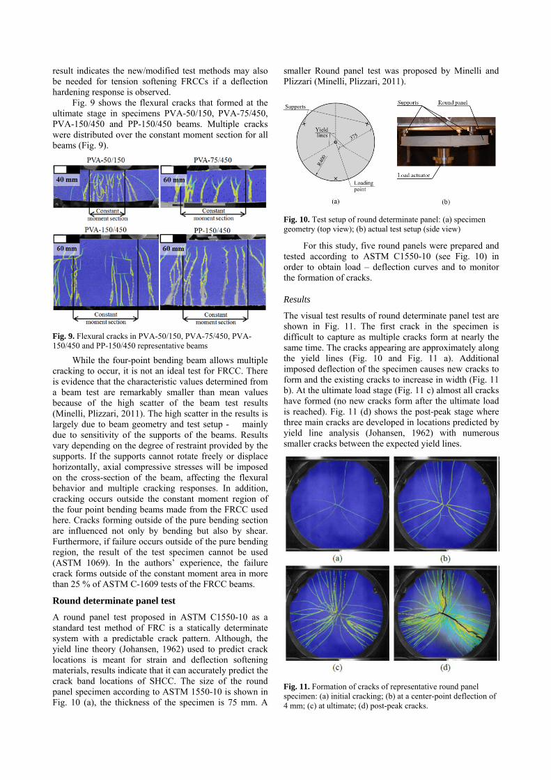
Fig. 9 shows the flexural cracks that formed at the ultimate stage in specimens PVA-50/150, PVA-75/450, PVA-150/450 and PP-150/450 beams. Multiple cracks were distributed over the constant moment section for all beams (Fig. 9).
Fig. 9. Flexural cracks in PVA-50/150, PVA-75/450, PVA-150/450 and PP-150/450 representative beams
While the four-point bending beam allows multiple cracking to occur, it is not an ideal test for FRCC. There is evidence that the characteristic values determined from a beam test are remarkably smaller than mean values because of the high scatter of the beam test results (Minelli, Plizzari, 2011). The high scatter in the results is largely due to beam geometry and test setup - mainly due to sensitivity of the supports of the beams. Results vary depending on the degree of restraint provided by the supports. If the supports cannot rotate freely or displace horizontally, axial compressive stresses will be imposed on the cross-section of the beam, affecting the flexural behavior and multiple cracking responses. In addition, cracking occurs outside the constant moment region of the four point bending beams made from the FRCC used here. Cracks forming outside of the pure bending section are influenced not only by bending but also by shear. Furthermore, if failure occurs outside of the pure bending region, the result of the test specimen cannot be used (ASTM 1069). In the authors’ experience, the failure crack forms outside of the constant moment area in more than 25 % of ASTM C-1609 tests of the FRCC beams.
Round determinate panel test
A round panel test proposed in ASTM C1550-10 as a standard test method of FRC is a statically determinate system with a predictable crack pattern. Although, the yield line theory (Johansen, 1962) used to predict crack locations is meant for strain and deflection softening materials, results indicate that it can accurately predict the crack band locations of SHCC. The size of the round panel specimen according to ASTM 1550-10 is shown in Fig. 10 (a), the thickness of the specimen is 75 mm. A
smaller Round panel test was proposed by Minelli and Plizzari (Minelli, Plizzari, 2011).
Fig. 10. Test setup of round determinate panel: (a) specimen geometry (top view); (b) actual test setup (side view)
For this study, five round panels were prepared and tested according to ASTM C1550-10 (see Fig. 10) in order to obtain load – deflection curves and to monitor the formation of cracks.
Results
The visual test results of round determinate panel test are shown in Fig. 11. The first crack in the specimen is difficult to capture as multiple cracks form at nearly the same time. The cracks appearing are approximately along the yield lines (Fig. 10 and Fig. 11 a). Additional imposed deflection of the specimen causes new cracks to form and the existing cracks to increase in width (Fig. 11 b). At the ultimate load stage (Fig. 11 c) almost all cracks have formed (no new cracks form after the ultimate load is reached). Fig. 11 (d) shows the post-peak stage where three main cracks are developed in locations predicted by yield line analysis (Johansen, 1962) with numerous smaller cracks between the expected yield lines.
Fig. 11. Formation of cracks of representative round panel specimen: (a) initial cracking; (b) at a center-point deflection of 4 mm; (c) at ultimate; (d) post-peak cracks.
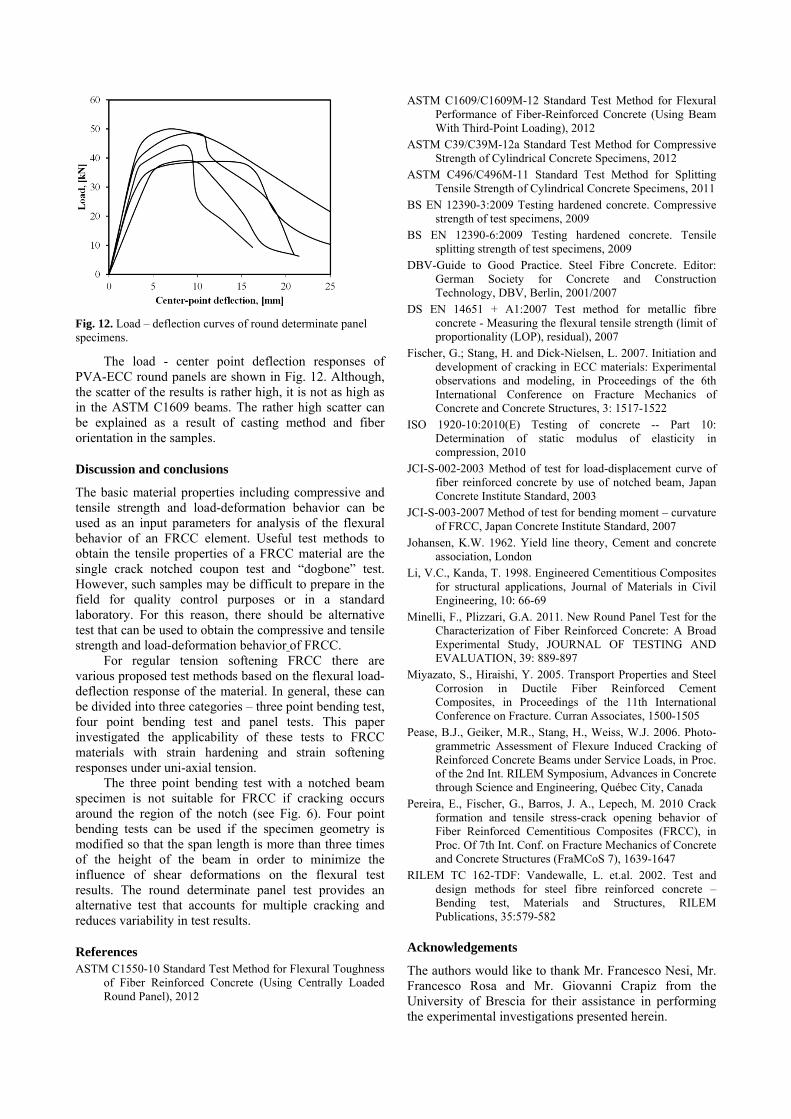
Fig. 12. Load – deflection curves of round determinate panel specimens.
The load - center point deflection responses of PVA-ECC round panels are shown in Fig. 12. Although, the scatter of the results is rather high, it is not as high as in the ASTM C1609 beams. The rather high scatter can be explained as a result of casting method and fiber orientation in the samples.
Discussion and conclusions
The basic material properties including compressive and tensile strength and load-deformation behavior can be used as an input parameters for analysis of the flexural behavior of an FRCC element. Useful test methods to obtain the tensile properties of a FRCC material are the single crack notched coupon test and “dogbone” test. However, such samples may be difficult to prepare in the field for quality control purposes or in a standard laboratory. For this reason, there should be alternative test that can be used to obtain the compressive and tensile strength and load-deformation behavior of FRCC.
For regular tension softening FRCC there are various proposed test methods based on the flexural load-deflection response of the material. In general, these can be divided into three categories – three point bending test, four point bending test and panel tests. This paper investigated the applicability of these tests to FRCC materials with strain hardening and strain softening responses under uni-axial tension.
The three point bending test with a notched beam specimen is not suitable for FRCC if cracking occurs around the region of the notch (see Fig. 6). Four point bending tests can be used if the specimen geometry is modified so that the span length is more than three times of the height of the beam in order to minimize the influence of shear deformations on the flexural test results. The round determinate panel test provides an alternative test that accounts for multiple cracking and reduces variability in test results.
References ASTM C1550-10 Standard Test Method for Flexural Toughness
of Fiber Reinforced Concrete (Using Centrally Loaded Round Panel), 2012
ASTM C1609/C1609M-12 Standard Test Method for Flexural Performance of Fiber-Reinforced Concrete (Using Beam With Third-Point Loading), 2012
ASTM C39/C39M-12a Standard Test Method for Compressive Strength of Cylindrical Concrete Specimens, 2012
ASTM C496/C496M-11 Standard Test Method for Splitting Tensile Strength of Cylindrical Concrete Specimens, 2011
BS EN 12390-3:2009 Testing hardened concrete. Compressive strength of test specimens, 2009
BS EN 12390-6:2009 Testing hardened concrete. Tensile splitting strength of test specimens, 2009
DBV-Guide to Good Practice. Steel Fibre Concrete. Editor: German Society for Concrete and Construction Technology, DBV, Berlin, 2001/2007
DS EN 14651 + A1:2007 Test method for metallic fibre concrete - Measuring the flexural tensile strength (limit of proportionality (LOP), residual), 2007
Fischer, G.; Stang, H. and Dick-Nielsen, L. 2007. Initiation and development of cracking in ECC materials: Experimental observations and modeling, in Proceedings of the 6th International Conference on Fracture Mechanics of Concrete and Concrete Structures, 3: 1517-1522
ISO 1920-10:2010(E) Testing of concrete -- Part 10: Determination of static modulus of elasticity in compression, 2010
JCI-S-002-2003 Method of test for load-displacement curve of fiber reinforced concrete by use of notched beam, Japan Concrete Institute Standard, 2003
JCI-S-003-2007 Method of test for bending moment – curvature of FRCC, Japan Concrete Institute Standard, 2007
Johansen, K.W. 1962. Yield line theory, Cement and concrete association, London
Li, V.C., Kanda, T. 1998. Engineered Cementitious Composites for structural applications, Journal of Materials in Civil Engineering, 10: 66-69
Minelli, F., Plizzari, G.A. 2011. New Round Panel Test for the Characterization of Fiber Reinforced Concrete: A Broad Experimental Study, JOURNAL OF TESTING AND EVALUATION, 39: 889-897
Miyazato, S., Hiraishi, Y. 2005. Transport Properties and Steel Corrosion in Ductile Fiber Reinforced Cement Composites, in Proceedings of the 11th International Conference on Fracture. Curran Associates, 1500-1505
Pease, B.J., Geiker, M.R., Stang, H., Weiss, W.J. 2006. Photo-grammetric Assessment of Flexure Induced Cracking of Reinforced Concrete Beams under Service Loads, in Proc. of the 2nd Int. RILEM Symposium, Advances in Concrete through Science and Engineering, Québec City, Canada
Pereira, E., Fischer, G., Barros, J. A., Lepech, M. 2010 Crack formation and tensile stress-crack opening behavior of Fiber Reinforced Cementitious Composites (FRCC), in Proc. Of 7th Int. Conf. on Fracture Mechanics of Concrete and Concrete Structures (FraMCoS 7), 1639-1647
RILEM TC 162-TDF: Vandewalle, L. et.al. 2002. Test and design methods for steel fibre reinforced concrete – Bending test, Materials and Structures, RILEM Publications, 35:579-582
Acknowledgements
The authors would like to thank Mr. Francesco Nesi, Mr. Francesco Rosa and Mr. Giovanni Crapiz from the University of Brescia for their assistance in performing the experimental investigations presented herein.