EVALUATION OF SEVERAL BRIDGE DECK PROTECTIVE SYSTEMS
88
FHWA/ NJ-81/003 81-003-7783 EVALUATION OF SEVERAL BRIDGE DECK . PROTECTIVE SYSTEMS RICHARD M. WEED AUTHOR DIVISION OF RESEARCH AND DEMONSTRATION NEW JERSEY STATE DEPARTMENT OF TRANSPORTATION AUGUST 1980 FINAL REPORT Prepared By New Jersey Department of Transportation Division of R es ear E h and Demonstration In Cooperation With U. S. Department of Transportation Federal Highway Administration
Transcript of EVALUATION OF SEVERAL BRIDGE DECK PROTECTIVE SYSTEMS

FHWA/ NJ-81/003
81-003-7783
EVALUATION OF SEVERAL BRIDGE DECK
. PROTECTIVE SYSTEMS
RICHARD M. WEED AUTHOR
D I V I S I O N OF RESEARCH AND DEMONSTRATION
NEW JERSEY STATE DEPARTMENT OF TRANSPORTATION
AUGUST 1980
FINAL REPORT
Prepared By
New Jersey Depar tment of Transpor ta t ion D iv is ion of R es ear E h a n d Demonstration
I n Coopera t ion W i t h U. S . D e p a r t m e n t of T r a n s p o r t a t i o n F e d e r a l H ighway A d m i n i s t r a t i o n

TECHNICAL REPORT STANDARD TITLE PAGE
1. Report No.
FHWA/NJ-81/003 2. Government Accession No.
9. Performing Organization Nomr and Address
New Jersey Department of Transportation Division of Research and Demonstration 1035 Parkway Avenue Trenton, New Jersey 08625
Federal Highway Administration Washington, D. C.
12. Sponsoring Agoncy Name and Address
1.5. Supplemmtary Notas
17. Key Words
Bridge decks, protect ive systems; membranes, spa l l i ng ,
3. Recipiont's Catalog No.
\ C l W b A Y 18. Disnibution Srotunm~
No r e s t r i c t i o n s
5. Roport Date
August 1980 6. Performing Orgonization Code
19. Socurity Classif. (of chis mpoet)
Unclassified
8. Performing Organization Report NO.
81 -003-7783 10. Work Unit No.
20. k a r r i r y Classif. (of this p a q d 21. No. 0 6 Pagas 2 2 Price
Unclassified 86
11. Contraa or Gront No.
N.J. HPR Study 7783 13. Type of Report and Period Covered
Final Report ~
14. Sponsoring Agency Code
16. Abrtroct
This report detai ls the i n s t a l l a t i o n and evaluat ion of t en d i f f e r e n t bridge deck protect ive systems. l i q u i d rubberized asphalt, two preformed sheet systems, one ro l l -on fabric system, latex-rnodified concrete, high densi ty concrete, epoxy-coated r e in fo rc ing steel, galvanized reinforcing steel , and internal ly-sealed concrete. Most i n s t a l l a t i o n s involve a t least two test decks.
These include asbestos-mcdified asphal t , hot-applied

Abstract !Continued 1
A l l are considered ten ta t ive ly acceptable based on the i r performance t o date although the Department's Design and Maintenance forces have developed d i s t i n c t preferences based on ease of i n s t a l l a t i o n , cos t and apparent effectiveness. A l l systems w i l l continue to be monitored f o r several years as p a r t of another study . As a fu r the r a id to designers, Appendix V I contains charts useful i n making realist ic comparisons between l e s s expensive but shrter l ived systems and more expensive but longer l ived systems. l i f e of a membrane system (shor t l i ved ) are known as well as the cos t of some more elaborate system, these charts enable the user t o determine the expected l i f e required f o r t h e more expensive system to be economically equivalent t o the membrane system.
For example, if the cos t and expected

NOTICE
The Sta te of New Je r sey and t h e United S t a t e s Covernment.,do not endorse
products o r manufacturers. Trade o r manufacturers' names appear h e r e i n
s o l e l y because they are considered e s s e n t i a l t o the o b j e c t of t h i s r e p o r t .
DISCLAIMER STATEMENT
The contents of t h i s r e p o r t reflect the views o f the author who is
responsible f o r t h e facts and the accuracy of the data presented he re in .
The contents do no t necessa r i ly reflect t h e o f f i c i a l views o r p o l i c i e s
of the New Jersey Department of Transportat ion o r the Federal Highway
Administration. This r e p o r t does no t c o n s t i t u t e a s t anda rd , s p e c i f i c a t i o n ,
o r r egu la t ion .
i

r
ACKNOWLEDGEMENT
The writer wishes t o acknowledge the cooperation and assis tance of the many individuals i n the bureaus of Construction Practices, S t ruc tura l Design, and Maintenance who furnished much of the information contained i n t h i s report . The Bureau of Construction Practices, i n pa r t i cu la r , provided construction and cos t d a t a fo r severa l of the systems including a l l of the d a t a per ta ining t o internally-sealed concrete.
ii

TABLE O F CONTENTS
1.0 SUMMARY AND CONCLUSIONS ....................................... 1
2.0 BACKGROUND .................................................... 2
3.0 METHODS O F EVALUATION ......................................... 4
3 . 1
4.0
4.1
MOISTURE S E N S I N G ELECTRODES ................................... 6 SYSTEMS UNDER T E S T ............................................ 8
ASBESTOS-MODIFIED ASPHALT SYSTEM .............................. 8
4.2 HOT-APPLIED L I Q U I D RUBBERIZED ASPHALT SYSTEM ................. 1 2
4.3 ROYSTON PREFORMED SHEET MEMBRANE ............................. 13
4.4 GRACE PREFORMED S H E E T MEMBRANE ............................... 14
4.5 PETROMAT MEMBRANE ............................................ 15
4.6 LATEX-EIODIF'IED CONCRETE ....................................... 17
4.7 LOWSLUMP HIGH-DENSITY CONCRETE .............................. 1 9
4 . 8 EPOXY-COATED REINFORCING STEEL ............................... 20
4.9 GALVANIZED REINFORCING STEEL ................................. 21 4.10 INTERNALLY SEALED CONCRETE .................................. 2 2
5.0 TENTATIVE EVALUATIONS O F TEST SYSTEMS ........................ 24
5.1 MEMBRANE SYSTEMS ............................................. 24
5.2 LATEX-MODIFIED CONCRETE AND LOWSLUMP HIGH-DENSITY CONCRETE .. 29 5 . 3 EPOXY-COATED AND GALVANIZED REINFORCING STEEL ................ 30
5.4 INTERNALLY SEALED CONCRETE ................................... 30
6.0 DEPTH O F COVER STUDY ......................................... 30
6 . 1 B A S I C PREMISE ................................................ 30
6.2 EVALUATION O F THE PACHOMETER ................................. 31
6.3 D E S C R I P T I O N O F TEST BRIDGES .................................. 32
6.4 ANALYSIS O F DEPTH O F C O m R MEASUREMENTS ...................... 32
iii

TABLE OF CONTENTS (Cont.)
6.5 DEVELOPMENT OF A DEPTH OF COVER SPECIFICATION ....'............ 36
7.0 REFERENCES .................................................... 38
APPENDIX I SPECIFICATIONS FOR MOISTURE SENSING ELECTRODES ....... 39
APPENDIX I1 MOISTURE SENSING ELECTRODE LOCATIONS ................. 41
APPENDIX I11 MOISTURE SENSING ELECTRODE READINGS .................. 49 APPENDIX IV IDENTIFICATION OF TEST BRIDGES ....................... 64
APPENDIX V DESCRIPTION OF AN INSTALLATION OF LATEX-MODIFIED
CONCRETE ............................................. 69 .
APPENDIX V I DEVELOPMENT OF ECONOMIC EQUIVALENCE CHARTS ............ 73
iv

1 . 0 SUMMARY AND CONCLUSIONS
Although a l l systems tested under t h i s s tudy are copsidered t en ta -
t i v e l y acceptable based on the i r performance t o date, both our Design
and Maintenance fo rces have developed d i s t i n c t - p r e f e r e n c e s based on
speed and ease o f i n s t a l l a t i o n , c o s t , and apparent e f f ec t iveness . For
repair of e x i s t i n g decks t h a t are n o t badly d e t e r i o r a t e d , patching
followed by a preformed sheet membrane and a bituminous concrete wearing
course is preferred. For badly d e t e r i o r a t e d decks r equ i r ing s u b s t a n t i a l
removal and replacement of concrete , the top surface is scarified and
replaced with e i ther latex-modified mortar o r high dens i ty concrete.
For new decks o r those r e q u i r i n g complete reconstruct ion, the top mat
of r e in fo rc ing steel is usua l ly protected wi th an epoxy coat ing ar,d
normal s t r u c t u r a l concrete is used.
galvanizing had been favored u n t i l FHWA Notice N5140.10 restricted
further use of t h i s system on Federal-aid p r o j e c t s pending more
p o s i t i v e proof o f its e f fec t iveness . 1
(Because of its ease of handling, 1
It had o r i g i n a l l y been planned t o evaluate the e f f ec t iveness of
the waterproofing membrane systems by means of moisture sensing
e l e c t r o d e s placed beneath the membranes during i n s t a l l a t i o n .
some long-term t r ends appear to e x i s t , the data gathered i n t h i s manner
turned o u t t o be considerably less conclusive than was expected, due
p r imar i ly t o t h e unce r t a in ty o f the actual source of the r e l a t i v e l y
small amounts of moisture that were detected. This is discussed i n
more detail i n Sect ion 5.1.
Although
The moisture sensing electrode d a t a is included i n t h i s r e p o r t
because i t may be o f i n t e r e s t t o others who have used t h i s method o r
who may be consider ing the use of similar instrumentation. However,
- 2 -
f o r the purposes of this study, the evaluations of the membrane systems
r e l y almost en t i re ly on the co l lec t ive judgement of the several engineers
who witnessed these ins t a l l a t ions p l u s the periodic visual inspections
by Research personnel.
2.0 BACKGROUND One of the most ser ious destruct ive phenomena i n evidence on a
large percentage of concrete bridge decks throughout the country is
spa l l ing , the breaking away of large chunks of concrete from the deck
surface. This is a t t r ibu ted t o the corrosion and subsequent expansion
of the top mat of reinforcing steel resu l t ing from the penetration of
water and deicing chemicals.
I n theory, the spa l l i ng problem can be solved i f a means can be
found t o prevent the corrosion of t h e re inforcing steel.
are possible basic approaches:
The following
A. Prevent corrosive materials from reaching the steel
1. Waterproof membrane on deck
2. Protective coating on steel
Avoid corrosion by other means
1.
2. Cathodic protection
B.
Stainless steel o r other spec ia l a l loys
The methods l i s t e d under Category ttBn were b r i e f ly invest igated a t
the beginning of the study and then excluded from further consideration.
Although stainless reinforcing steel was commercially ava i lab le and
probably could have solved the spa l l i ng problem,its cos t was prohibi t ive.
An economic comparison indicated tha t a bridge deck could be repaired
severa l times a t less overa l l cos t than t h a t of an i n s t a l l a t i o n using
s t a i n l e s s reinforcing steel. Cathodic protection was a l s o considered

- 3 -
b u t was judged by the Department's Design and Maintenance forces t o be
a more exot ic system than was desired fo r the type of appl icat ions
expected t o be routinely encountered i n the future .
It was decided t o limit candidate systems t o t h e two general types
l i s ted under Category "A1', bridge deck waterproofing membranes (or
similar barriers) and protective coatings fo r the reinforcing steel.
Further , s ince this study was i n i t i a t e d largely a t the request of our
Maintenance forces who needed an effect ive way t o repair a growing
backlog of badly spal led decks, it was decided t o concentrate on
systems which had already shown promise in previous invest igat ions by
others . This policy was followed throughout the study except fo r the
l a s t i n s t a l l a t i o n which u t i l i zed a more h igh ly experimental system
(internally-sealed concrete ) . I n order t o provide a thorough and realistic test of the experi-
mental systems, i t was decided that they would be in s t a l l ed on actual
bridge decks.
were s t ruc tu ra l ly sound but which exhibited extensive surface de ter ior -
a t ion . The necessary repairs and surface preparations were made as
required fo r each of the protective systems tested. (Chloride contents
and depth of cover over the reinforcing steel were not measured because
the Department had not acquired the necessary equipment f o r t h i s a t the
time the study waa initiated.
other br idges a t a later dateand is discussed i n Section 6 of this repor t . 1
Test sites selected fo r this study were decks which
A depth of cover study was performed on
Since most of New Jersey 's main arteries are heavily t ravel led
and subjected to subs tan t ia l volumes of truck t r a f f i c , suitable test
bridges were f a i r l y p len t i fu l . It is estimated t h a t a l l tes t bridges
a r e on routes having an AADT of 20,000 or more with the percentage of

- 4 -
heavy truck traffic ranging from 5% t o 15%.
The deicing compound used i n t h i s state is a 4 : l n ix ture of rock
salt and calcium chlor ide but the actual appl icat ion rate on the tes t
bridges is not known.
per lane mile but the truck d r ive r s are ins t ruc ted t o tu rn o f f the
The standard appl icat ion rate is 250 to 350 pounds
spreader when passing over a bridge deck.
these ins t ruc t ions are not always followed and, even when they are, i t
is known tha t a subs t an t i a l amount of salt is tracked onto the decks by
t r a f f i c ,
However, i t is suspected that
I n i t i a l l y , it w a s planned t o have two test decks f o r each o f the
protect ive systems included i n t h i s study.
gressed, a number of addi t iona l bridges were included as part of the
FHWA's experimental cost-effect ive bridge deck reconstruct ion program.
However, as the study pro-
Typically, these i n s t a l l a t i o n s were made on bridge decks that were
badly deter iorated or which contained chloride l eve l s above 2 l b s . /c .y . , the threshold above which it is believed more economiczl t o remove and
replace the e n t i r e deck. 2
3.0 METHODS OF EVALUATION
Since the object ive of t h i s study was t o i den t i fy bridge deck
protect ive systems which could be readi ly used by the Maintenance
Department t o repair deter iorated decks, a primary concern was speed
and ease of i n s t a l l a t i o n . In most cases, it was des i red t o be able t o
d ive r t traffic i n the morning, complete the repairs during the day, and
open the bridge i n time. for t h e la te afternoon rush hour. Furthermore,
from the standpoint of the Maintenance Department, a desirable system
would require ne i ther highly t ra ined workmen nor special equipment.
The effect iveness of the systems was evaluated by two methods.

- 5 -
A l l systems were subjected t o periodic v isua l inspec t ions and, i n
a d d i t i o q t h e waterproofing membranes were evaluated by means of special
e lectrodes placed so as t o sense the presence of moisture d i r e c t l y beneath
the membranes.
,
The v isua l inspections were made t o observe any obvious’
physical de te r iora t ion while the electrodes made it possible t o de tec t any
subs t an t i a l accumulations of water beneath the membranes.
A t h i r d means of evaluation w a s cos t effect iveness . A more cos t ly repair
would st i l l be considered of value if it were f e l t i t could subs tan t ia l ly
extend the usefu l se rv ice l i f e of a bridge deck.
development of char t s usefu l i n making economic comparisons between subs t an t i a l ly
Appendix V I presents the .
d i f f e ren t systems.
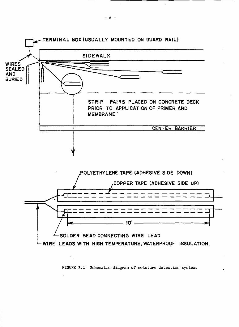
3 .1 MOISTURE SENSING ELECTRODES
A schematic drawing of t h e moisture sensing electrodes is shown in
The electrodes cons is t of t h i n copper tape, 1/2 inch wide by Figure 3.1.
10 f t . long by 0.0015 inches thick. The copper t a p e is first attached t o
polyethylene t ape (duct tape) and then placed on the surface of the bridge
deck.
neath the bituminous wearing course t o a terminal box a t one end of the
br idge.
contained i n Appendix I.
Wire leads wi th waterproof high-temperature insu la t ion are run under-
More extensive information on these instrumentation materials is
Normally, about 10 pairs of these s t r i p s were placed on each test deck.
Some were placed a t specific locat ions such as close t o the curb, near the
end of the br idge, o r next t o any joints. Others were located randomly on
the decks, some i n the wheelpaths and others between the wheelpaths, and
one (cont ro l ) was usual ly placed on the approach slab a t tke end of the
bridge where there was t o be a bituminous overlay but no membrane. The
exact locat ions of the electrodes are shown i n the diagrams i n Appendix 11.
To determine the ex i s t ing wetness condition of t h e concrete surfaces
- 6 -
TERMINAL BOX (USUALLY MOUNTED ON GUARD RAIL) C Y I \
/- WIRES SEALED AND BURIED
SIDEWALK
STRIP PAIRS PLACED ON CONCRETE DECK PRIOR TO APPLICATION OF PRIMER AND MEMBRANE '
CENTER BARRIER
POLYETHYLENE TAPE (ADHESIVE SIDE DOWN) /
I-- 10'.
SOLDER BEAD CONNECTING WIRE LEAD L WI RE LEADS WITH HIGH TEMPERATURE, WATERPROOF INSULATION.
FIGURE 3.1 Schematic diagram of moisture de tec t ion system.

- 7 -
upon which the electrodes were placed, e l e c t r i c a l resistance readings
were taken between the two s t r i p s of each p a i r by means of an ordinary
ohm-meter.
and salt leve ls , a series of ca l ibra t ion tests were made.
indicated t h a t completely dry concrete would produce readings of a t
least 20,000 ohms and as high as several mill ion ohms. Readings i n
the range from 20,000 ohms down to about 2,000 ohms a re considered
uncertain as far as the presence of moisture is concerned. Below
2,000 ohms, moisture is almost cer ta in ly present and, below approxi-
mately 500 ohms, i t is believed that both salts and moisture a re
present. The bridge deck readings f o r t h i s study were taken on a
periodic b a s i s and, on cccasion, were taken short ly after a heavy
r a i n i n an a t tempt t o detect any leaks i n the membranes.
By instrumenting a test s l a b and control l ing both moisture
These
While performing the ca l ibra t ion tests, two unexpected observa-
When a resis tance reading was taken, the ohm-meter t ions were made.
of ten tended t o d r i f t f o r a few seconds before s tab i l iz ing .
reversing the two leads t o the electrodes u s u a l l y produced a s l igh t ly
d i f f e ren t reading. Therefore, it becaae standard procedure t o allow
time fo r the readings to s t a b i l i z e and to make both d i r e c t and reverse
measurements and average the r e su l t s . A l l t h e d a t a recorded i n
Appendix I11 were obtained i n t h i s manner.
Also,
Although the terminal s t r i p s were housed i n closed aluminum
junction boxes which were mounted f a i r l y inconspicuously near the
ends of the test br idges , nearly a l l of them were eventually destroyed
by vandals.
f i ve years o r more although, i n some cases, i t was less.
of the vandalism, a l l future long-term monitoring w i l l have t o be
In most cases, readings were obtained f o r periods of
A s a result

- a -
accomplished by means other than the moisture-sensing electrodes.
v i sua l observations w i l l be included as pa r t of another study and,if
it appears that addi t ional useful information can be obtained, chlor ide
measurements and half c e l l readings may be taken.
Annual
4 . 0 SYSTEMS UNDER TEST
This sect ion provides general information pertaining t o each of
the ten systems under test and is summarized i n Table 4.1. More addi t iona l
information including ident i f ica t ion of the test b r idges is contained i n
Appendix I V .
4 . 1 ASBESTOS-MODIFIED ASPHALT SYSTEM
This is a bituminous concrete system which consis ts of a r e l a t i v e l y
t h i n membrane course followed by a thicker wearing course o r normal
bituminous paving.
amount of asbestos fibers (supplied by Johns Manville) t o o f f s e t the
high asphalt content of approximately 15%.
put down a t a thickness of 1/2 inch t o 3 / 4 inch and, because of its
composition, a higher-than-normal placement temperature of 350°F o r
more is recommended.
The membrane mix uses a f i n e aggregate and a small
The membrane mix is usual ly
Advantages of t h i s system include low cos t and the a b i l i t y t o place
i t on a rough, uneven surface using standard equipment. Disadvantages
include the handling of the asbestos fibers a t the mixing p lan t and
the requirement of a higher than normal placement temperature.
sequent disadvantage is the withdrawal of Johns-Manville from the asbestos-
modified-asphalt market i n 1976.)
( A sub-
Due t o a delay i n placing the moisture sensing electrodes, plus the
fact that t h e paver w a s cold a t the start, the material was placed on .
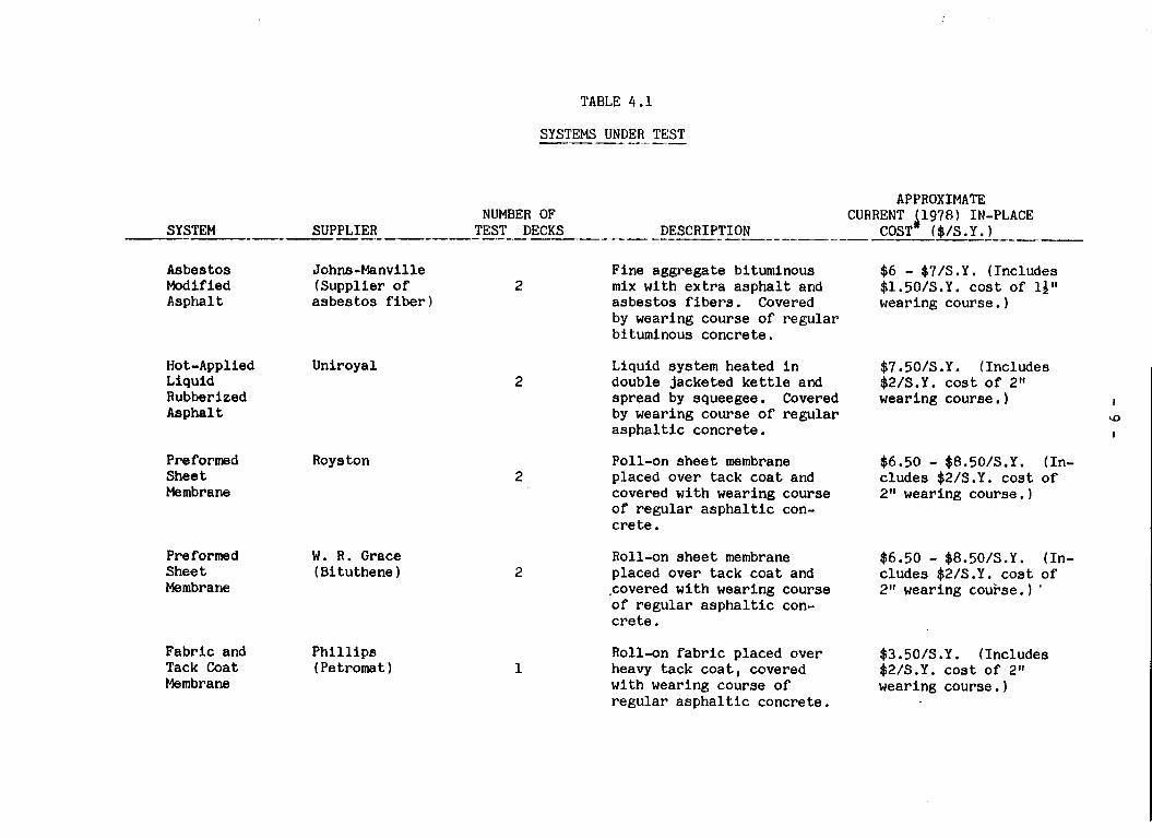
TABLE 4 . 1
SYSTEMS UNDER TEST
APPROXIMATE NUMBER OF CURRENT 519781 IN-PLACE
SUPPLIER TEST DECKS DESCRIPTION COST ($/S.Y. 1 --- --_-_- --------.-- -- ------ --------- - - ----_-___ SYSTEM -.--
Asbestos Johns -Manville F ine aggregate b i t uminous Modif led (Supplier of 2 mix w i t h extra asphalt and Asphalt asbestos fiber 1 asbestos f ibers . Covered
by wearing course of regular b i tuminous concrete .
Ho t-Applied Uniroyal Liquid Rubberized Asphalt
2
Preformed Sheet Membrane
Roys ton 2
Preformed W. R. Grace Sheet (Bituthene) Membrane
Fabric and Ph ill i p s Tack Coat ( Pe troma t 1 Membrane
2
1
Liquid system heated i n double jacketed ket t le and spread by squeegee. Covered by wearing course of regular asphaltic concrete.
Poll-on sheet membrane placed over tack coat and covered w i t h wearing course of regular asphaltic con- cre t e . Roll-on sheet membrane placed over tack coat and ,covered w i t h wearing course of regular asphaltic con- crete.
Roll-on fabric placed over heavy tack coat, covered wi th wearing course of regular asphaltic concrete .
$6 - $7/S.Y. (Includes $1.50/S.Y. cost of 13" wearing course. 1
$7.50/S .Y. (Includes $2/S.Y. cost of 2" wearing course, ) I
u3
I
$6.50 - $8.50/S.Y. ( In - cludes $2/S.Y. cost of 211 wearing course. 1
$6.50 - $8.50/S.Y. ( I n - cludes $2/S.Y. cost of 2" wearing course. 1 '
$3.50/S .Y. (Includes
wearing course, ) $2/S.Y. cost of 2"

APPROXIMATE NUMBER OF CURRENT (1978) IN-PLACE
DESCRIPTION COST* ($/S.Y. 1 l_l_-._-._____-- - - -------I_- -- TEST DECKS --- ---- SUPPLIER ---- SYSTEM
Latex Dow Mod i f ied Concrete
Low-Slump Various High-Density Concrete (Iowa Sys tem
Epoxy-Coa t e d Various Reinforc ing Steel
Galvanized Re in fo rc ing Steel
Various
Th i s system inc ludes the 28 removal by s c a r i f i c a t i o n
(or a i r harmer) of the deteriorated t o p s u r f a c e of the bridge deck fo l - lowed by replacement w i t h latex-modified mortar.
4
2
a
T h i s system is e s s e n t i a l l y t he same as t h e latex- modified-mortar system excep t t h a t low-slump h igh-dens i ty conc re t e is used.
P r o t e c t i v e c o a t i n g to pre- v e n t water and d e i c i n g s a l t s from cor rod ing the r e i n f o r - c i n g s teel . Both upper and lower mats of r e i n f o r c i n g steel were coated for one deck, only t h e upper mat was coated for t h e other .
Unlike t h e epoxy c o a t i n g which p reven t s c o r r o s i o n , ga lvan iz ing is a sacrifical c o a t i n g which is be l i eved to reduce t h e l i k e l i h o o d and s e v e r i t y of s p a l l i n g . For t h e s e i n s t a l l a t i o n s , both the upper and lower mats were ga lvan ized .
$20 - $50/S.Y. (Depending upon amount of p repa ra to ry work r e q u i r e d . 1
$11 - Q3WS.Y. (These f i g u r e s based on new c o n s t r u c t i o n only .
$14/S on ly ?
mats epoxy
$34 -
I P
Y . for upper mat
coating).
$27/S.Y. for both 0
extra coat due to I
$50/S.Y. for both upper and lower mats.

APPROXIMATE
COST ($/S.Y. 1 NUMBER OF CURRENT 51978) IN-PLACE
- - -__I.-___ SYSTEM SUPPLIER TEST DECKS DESCRIPTION I- -----_I_- ---. __._I_--_ C.---___---..--------_I_----
I n t e r n a l l y Monsanto 2 Wax beads r e p l a c e a por- Sealed (Supp l i e r of (Eastbound & t i o n of t h e sand i n a Concrete wax beads 1 Westbound non-air-entrained
decks of s t r u c t u r a l concrete mix. single span b r idge 1 h e a t is a p p l i e d t o t h e
After a pe r iod of cur ing ,
deck t o melt t h e wax and allow it t o flow i n t o t h e c a p i l l a r i e s .
$50/S.Y. ( T h i s cost i a based upon a r e l a t i v e l y small b r i d g e and does n o t i nc lude t h e cost o f t h e h e a t i n g equipment borrowed from FHWA. The cost would have been approximately $7O/S.Y, wi th t h e h e a t i n g equipment inc luded . )
#NOTE: The cost f i g u r e s g iven h e r e r e p r e s e n t t h e to ta l extra cost a t t r i b u t a b l e t o the p r o t e c t i v e system. i n s t a l l a t i o n s p l u s c u r r e n t estimates by t h e v a r i o u s s u p p l i e r s and , t h e r e f o r e , must be regarded as approximate.
These are based on a l i m i t e d number of r e l a t i v e l y small
- 12 -
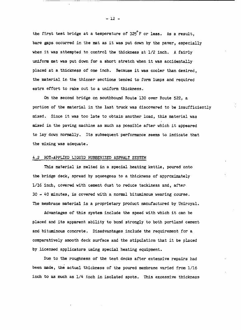
the fLrst test bridge a t a temperature of 325OF o r less.
bare gaps occurred i n the mat as i t was put d a m by the paver, espec ia l ly
when it was attempted to control the thickness a t 1/2 inch. A f a i r l y
uniform mat was put down f o r a shor t s t r e t c h when it was accidental ly
placed a t a thickness of one inch. Because it was cooler than des i red ,
the material i n the thinner sect ions tended t o form lumps and required
ex t ra e f f o r t t o rake out t o a uniform thickness.
As a result,
On the second bridge on southbound Route 130 over Route 522, a
portion of the material i n the last truck was discovered t o be in su f f i c i en t ly
mixed. Since i t was too la te t o obtain another load, t h i s mater ia l was
mixed i n the paving machine as much as possible after which i t appeared
t o lay down narmally. Its subsequent performance seems t o ind ica te t ha t
the mixing w a s adequate.
4.2 HOT-APPLIED LIQUID RUBBERIZED ASPHALT SYSTEM
This material is melted i n a special heating k e t t l e , poured onto
the bridge deck, spread by squeegees t o a thickness of approximately
1/16 inch, covered w i t h cement dus t t o reduce tackiness and, after
30 - 40 minutes, is covered with a normal bituminous wearing course.
The membrane material is a proprietary product manufactured by Uniroyal.
Advantages of t h i s system include the speed wi th which i t can be
placed and its apparent a b i l i t y t o bond strongly t o both portland cement
and bituminous concrete. Disadvantages include the requirement f o r a
comparatively smooth deck surface and the s t ipu la t ion t h a t i t be placed
by l icensed appl ica tors using spec ia l heating equipment.
Due t o the roughness of the test decks a f t e r extensive r epa i r s had
been made, the actual thickness of the poured membrane varied from 1/16
inch t o as much as 1/4 inch i n i so l a t ed spots. This excessive thickness

- 13 -
is believed t o be the cause of the formation of several-"bleed throught1
s p o t s which appeared after t h e wearing course was placed. These were
gradual ly worn away by traffic and disappeared i n about two weeks.
Some ope ra t iona l problems were experienced wi th t h e hea t ing k e t t l e
du r ing the treatment of the test deck on Route 46 over the Erie-Lackawanna
Railroad. However, judging from its subsequent performance, t h i s d i d no t
affect the i n t e g r i t y of the membrane placed on t h i s deck.
4 . 3 ROYSTON PREFORMED SHEET MEMBRANE
The manufacturer, Royston, markets t h i s product as "Bridge Membrane
It is a heat modified b i t m i n o w r e s i n composition wi th an No. 10."
i nne r l a y e r o f open weave fiberglass mesh and is normally supplied i n
fou r f o o t lor4 r o l l s .
a special primer is app l i ed with p a i n t r o l l e r s .
hour, the pr imer is s u f f i c i e n t l y dry so that the membrane i tself can
be r o l l e d on i n t s l i g h t l y overlapping pa t t e rn . Edges and j o i n t s m u s t
be sealed wi th h2nd torches af ter which a bituminous wearing course is
appl ied .
After the patched bridge deck is swept c l e a n ,
After about one-half
Advantages of t h i s system are the ease and speed wi th which it can
be placed without s p e c i a l equipment o r t r a ined personnel and the wide
range of temperatures over which i t can be app l i ed .
t h e occasional necess i ty t o repair blisters (pockets of entrapped moisture
vapor) p r i o r to the placing of the wearing course.
m u s t not be allowed t o contact e x i s t i n g bituminous pavement s i n c e i t has
a softening effect.
A disadvantage is
Also, the primer
This aembrane is s l i g h t l y thicker than the Grace material ( t h e
o t h e r preformed sheet membrane tested i n t h i s s t u d y ) .
as much but it bonded less s t rong ly when first r o l l e d o u t by hand.
It d i d not wrinkle

- 14 -
This could be considered a n advantage i n t h a t it allows the workmen t o
a d j u s t i ts pos i t i on somewhat.
and was no t damaged by the metal tracks of the paver.
Once down, it appeared to be q u i t e secure
About one week after the membrane and wearing course were i n s t a l l e d
a t the Princeton Junction br idge, a small popout of t h e overlay material
was observed.
intended a t t h i s point due t o a n at tempt t o smooth o u t some i r r e g u l a r i t i e s
i n the bridge surface.
membrane i tself and was corrected by adding another t h i n l a y e r of wearing
course over the e n t i r e bridge,
It w a s discovered that the overlay was much th inne r than
The problem was no t f e l t t o be related t o the
Ancther i n s t a l l a t i o n of the Royston material a t a later da te demon-
strated t h a t i t could be appl ied success fu l ly a t temperatures s u b s t a n t i a l l y
below the recommended minimum 50'F.
cond i t ions required t h a t i t be done a t n i g h t , and the schedule was such
t h a t i t could no t be done u n t i l e a r l y November.
temperatures were i n the low 30's when the membrane was appl ied.
s p i t e o f t h i s , the cons t ruc t ion progressed normally and appears t o have
been s a t i s f a c t o r y .
This was a con t r ac t job, t raffic
A s a result , the
I n
4.4 GRACE PREFORMED SHEET MEMBRANE
The trade name of t h i s product is "Heavy Duty Bituthene" by
W. R . Grzce and Company. Similar t o the Royston membrane, t h i s product i s
a rubberized-asphalt compound w i t h an embedded woven mesh. It, too ,
is suppl ied i n r o l l s and r e q u i r e s a primer t o bond i t t o the bridge deck
p r i o r t o t h e a p p l i c a t i o n of the wearing course.
are sealed wi th a mastic material instead of the hand torches used wi th
the Royston membrane.
The edges and seams
,

- 15 -
The advantages and disadvantages are e s s e n t i a l l y the same as those
of the Royston system.
l a b o r but may r equ i r e some repair o f a i r pockets before paving.
material is th inne r and lighter than the Royston membrane and, t h e r e f o r e ,
somewhat easier t o handle.
steel tracks of t h e paver.
It is fast and easy t o apply with unsk i l l ed
The
It was deeply marked bu t n o t c u t by the
When the overlay was placed, unexpected r e f l e c t i o n cracks occurred
a t some of the seams (both long i tud ina l and t r a n s v e r s e ) immediately
behind the paver. However, these appeared t o be w e l l sealed by the
r o l l i n g process and were barely discernible afterwards.
This membrane, l i k e the Royston material, experienced a small popout
on the Princeton Junct ion bridge. As i n the o t h e r case, t h i s was n o t
a t t r i b u t e d t o the membrane itself and was corrected by adding another
t h i n l a y e r o f wearing course.
This system a l s o was i n s t a l l e d a t a second locat ior? w i t h temperatures
i n the mid-30fs, co lde r than the minimum of 40°F recommended f o r t h i s
product.
have been observed.
The cons t ruc t ion proceeded normally and no adverse effects
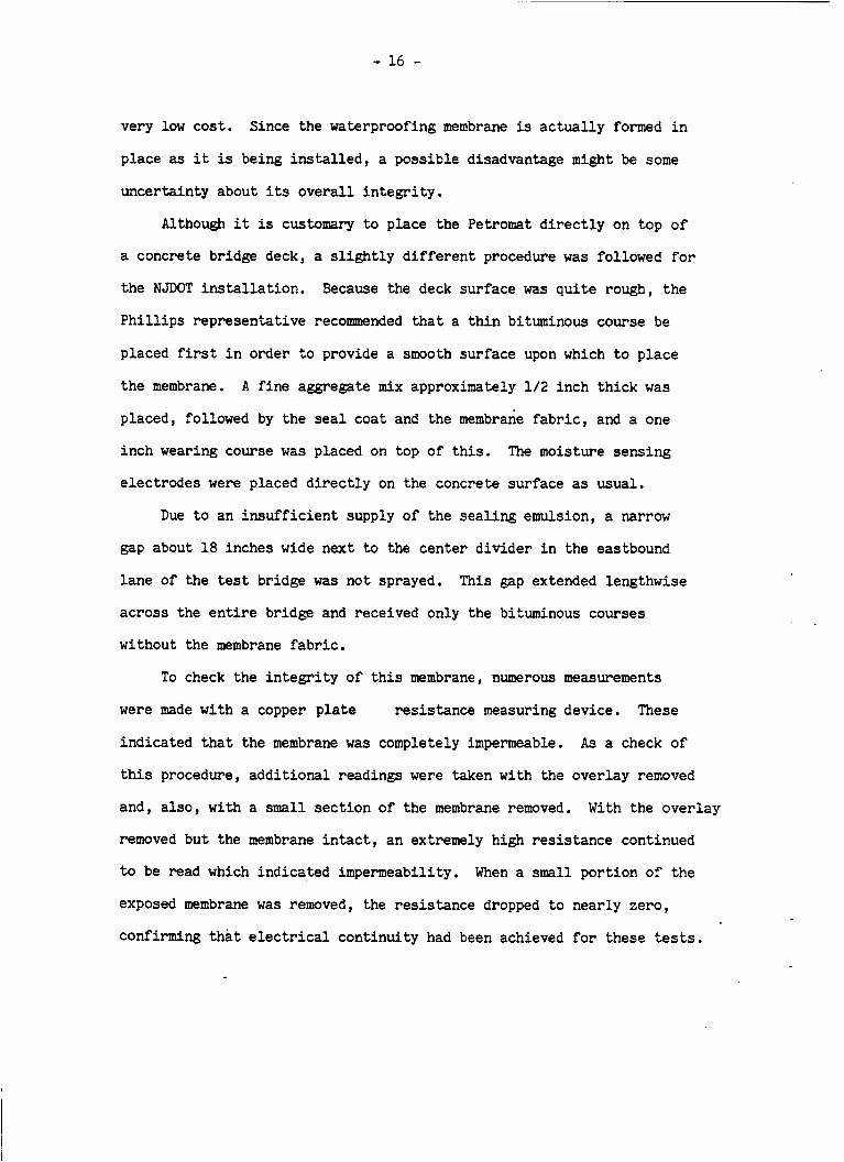
4.5 PETROMAT MEMBRANE
This membrane, manufactured by P h i l l i p s Petroleum Company, c o n s i s t s
of a non-woven polypropylene fabric which is saturated during i n s t a l l a t i o n
w i t h ei ther asphal t cement o r a s p h a l t emulsion.
t o 0.30 ga l . / s . y . ) is placed on t he surface t o be protected and the
Petromat fabric is r o l l e d onto t h i s seal coa t while i t is s t i l l tacky.
A conventional hot-mix wearing course is then placed over the fabric,
u sua l ly without an a d d i t i o n a l tack coat .
A heavy seal c o a t (0.25
Advantages of t h i s system are speed and ease of i n s t a l l a t i o n ar,d
- 16 -
very law cost . Since the waterproofing membrane is ac tua l ly formed i n
place as it is being i n s t a l l e d , a possible disadvantage might be some
uncertainty about its overal l in tegr i ty .
Although it is customary t o place the Petromat d i r ec t ly on top of
a concrete bridge deck, a s l i g h t l y d i f f e ren t procedure was followed f o r
the NJDOT in s t a l l a t ion . Because the deck surface was quite rough, the
P h i l l i p s representative recommended t h a t a th in bituminous course be
placed first i n order t o provide a s m o t h surface upon which t o place
the membrane. A f ine aggregate mix approximately 1 / 2 inch th ick was
placed, followed by the seal coat and the membrane fabric, and a one
inch wearing course was placed on top of t h i s . The moisture sensing
electrodes were placed d i r ec t ly on the concrete surface as usual.
Due t o an in su f f i c i en t supply of the sea l ing emulsion, a narrow
gap about 18 inches wide next t o the center divider i n the eastbound
lane of the test bridge was not sprayed.
across the e n t i r e bridge and received only the bituminous courses
without the membrane fabr ic .
This gap extended lengthwise
To check the in t eg r i ty of t h i s membrane, numerous measurements
were made w i t h a copper p l a t e res is tance measuring device. These
indicated t h a t the membrane w a s completely impermeable.
this procedure, addi t ional readings were taken wi th the overlay removed
and, a l so , wi th a small sect ion of the membrane removed.
removed but the membrane i n t a c t , an extremely high resis tance continued
t o be read which indicated impermeability. When a small portion of t h e
exposed membrane was removed, the resis tance dropped t o nearly zero,
confirming t h a t e l e c t r i c a l continuity had been achieved f o r these tests.
As a check of
With the overlay
- 17 -
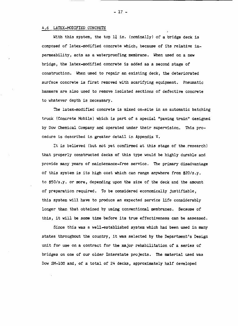
4.6 LATEX-MODIFIED CONCRETE
With t h i s system, the top 1 2 i n . (nominally) o f a bridge deck is
composed o f latex-modified concrete which, because of i'ts r e l a t i v e i m -
permeabi l i ty , acts as a waterproofing membrane.
bridge, the la tex-modif ied concrete is added as a second stage o f
cons t ruc t ion . When wed t o r e p a i r an e x i s t i n g deck, the d e t e r i o r a t e d
s u r f a c e concrete is first removed wi th s c a r i f y i n g equipment. Pneumatic
hammers are a l s o used t o remove i s o l a t e d sec t ions of de fec t ive concrete
t o whatever depth is necessary.
When wed on a new
The latex-modif ied concrete is mixed on-site i n an automatic batching
t ruck (Concrete Mobile) which is p a r t o f a s p e c i a l "paving train" designed
by Dow Chemical Company and operated under t h e i r supervis ion.
cedure is described i n greater d e t a i l i n Appendix V.
This pro-
It is believed ( b u t not y e t confirmed a t t h i s stage of the r e sea rch )
t h a t properly constructed decks of t h i s type would be highly durable and
provide many years of maintenance-free se rv ice .
o f t h i s system is its high c o s t which can range anywhere from $20/s.y.
t o $50/s.y. o r more, depending upon the s i z e of the deck and the amount
of p repa ra t ion required.
t h i s system w i l l have t o produce a n expected service l i f e considerably
longer than t h a t obtained by using conventional membranes. Because of
t h i s , i t w i l l be some time before its t r u e e f f ec t iveness can be assessed.
Since t h i s was a well-established system which had been used i n many
states throughout the country, i t was selected by the Department's Design
u n i t f o r use on a c o n t r a c t f o r the major r e h a b i l i t a t i o n of a series of
br idges on one of our o l d e r I n t e r s t a t e p ro jec t s .
Dow SM-100 and, of a t o t a l of 24 decks, approximately half developed
The primary disadvantage
To be considered economically j u s t i f i a b l e ,
The material used was

- l a -
extensive random cracking. Cores taken from these decks showed t h a t , i n
some cases, the cracks penetrated t o the depth of the steel. Since t h i s
could negate the effectiveness of t h i s system and possibly l ead t o pre-
mature f a i lu re , Dow w a s asked t o send an inspection team t o a sce r t a in
the causes and determine w h a t remedial ac t ion , i f any, should be taken.
After observing the cracked decks and analyzing several cores, the
Dow representative proposed the following explanations and recommendations:
1) The core analyses s h e d t h a t the cement and l a t ex contents
were very close t o the design values recommended by the
manufacturer. .Therefore, it w a s concluded t h a t these
factors d i d not contribute t o the cracking problem.
2) The recommended cure of 24 hours of moist condition followed
by 72 hours of open a i r curing is based upon a th in overlay
(two inches or less), ambient temperatures above 55OF, and
r e l a t ive humidities below 85% during the a i r cure period.
Due to various circumstances, these conditions were not met.
Because the bridges were badly de te r iora ted , up t o six inches
of defective concrete was removed a t many locat ions p r io r t o
the placement of the latex-modified concrete. Also, most of
the construction took place during September and October when
the weather was cool and frequently rainy. Therefore, i t is
possible that the deeper sect ions of l a t e x concrete d id not
cure su f f i c i en t ly to withstand the heavy loads imposed when
first opened t o traffic.
3) This par t icu lar contract called f o r a mortar mix of la tex-
modified concrete s ince i t was anticipa€ed that the depth
of the o v e r l a p e n t would be r e l a t ive ly thin. For greater
- 19 -
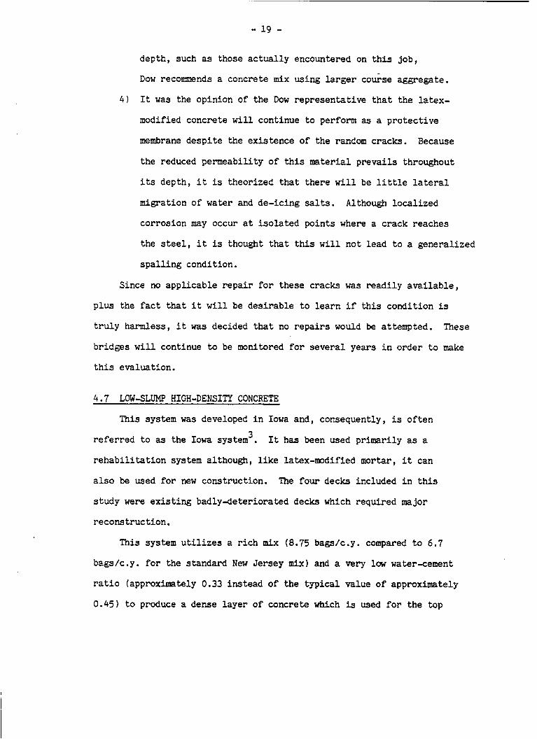
depth , such as those actually encountered on t h i s job,
Dow recommends a concrete mix using larger co&e aggregate.
It was the opinion of the Dow rep resen ta t ive t h a t the l a t ex -
modified concrete w i l l continue t o perform as a p r o t e c t i v e
membrane despi te the ex i s t ence of the random cracks. Because
the reduced permeabili ty of t h i s material p r e v a i l s throughout
its depth, it is theorized t h a t there will be l i t t l e la te ra l
migration of water and de-icing salts.
corrosion may occur a t isolated points where a crack reaches
the steel , i t is thought that t h i s w i l l not lead t o a general ized
s p a l l i n g condition.
4 )
Although loca l i zed
Since no app l i cab le r e p a i r f o r these cracks was r e a d i l y available,
p l u s the fact that i t w i l l be desirable t o learn i f t h i s condi t ion is
t r u l y harmless, i t was decided that no repairs would be attempted. These
bridges w i l l continue t o be monitored f o r s eve ra l years i n order t o make
t h i s evaluation.
4.7 LOW-SLUMP HIGH-DENSITY CONCRETE
This system was developed i n Iowa and, consequently, is o f t e n 3 referred to as the Iowa system .
r e h a b i l i t a t i o n system although, l ike latex-modified mortar, it can
a l s o be used f o r new construction. The f o u r decks included i n t h i s
s tudy were existing badly-deter iorated decks which required major
reconstruct ion.
It has been used p r imar i ly as a
This system u t i l i z e s a r ich mix (8.75 bags1c.y. compared t o 6.7
bags/c.y. f o r the standard New Je r sey mix) and a very low water-cement
r a t i o (approximately 0.33 instead of the typical value o f approximately
0.45) t o produce a dense l a y e r of concrete which i s used f o r the top
- 20 -
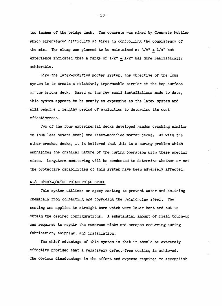
two inches of the bridge deck. ?he concrete was mixed by Concrete Mobiles
which experienced d i f f i c u l t y a t times i n cont ro l l ing the consistency of
the mix.
experience indicated tha t a range of 1/2" - + 1/2" was more realist ically
achievable.
The slump was planned to be maintained a t 3/4" + 1/4" but -
Like the latex-modified mortar system, the object ive of the Iowa
system is t o c rea te a r e l a t ive ly impermeable barrier a t the top surface
of the bridge deck. Based on the few small i n s t a l l a t i o n s made t o d a t e ,
t h i s system appears t o be nearly as expensive as the l a t ex system and
' w i l l require a lengthy period of evaluation to determine its cos t
effect iveness .
Two of the four experimental decks developed random cracking similar
t o (but less severe than) t h e latex-modified mortar decks. As with the
other cracked decks, i t is believed that t h i s is a curing problem which
emphasizes the cr i t ical nature of the curing operation w i t h these special
mixes. Long-term monitoring w i l l be conducted t o determine whether o r not
the protect ive capab i l i t i e s of t h i s system have been adversely affected.
4 .8 EPOXY-COATED REINFORCING STEEL
This system u t i l i z e s an epoxy coating t o prevent water and de-icing
chemicals f r o m contacting and corroding the reinforcing steel .
coating was applied t o straight bars which were later bent and cu t t o
obtain the des i red configurations.
was required t o repa i r the numerous nicks and scrapes occurring during
fabricat ion, shipping, and i n s t a l l a t i o n .
The
A subs tan t ia l amount of f i e l d touch-up
The chief advantage. of t h i s system is t h a t i t should be extremely
e f fec t ive provided tha t a r e l a t ive ly defect-free coating is achieved.
The obvious disadvantage is the e f f o r t and expense required t o accomplish

- 21 -
t h i s . Smll llholidaysll are not easy t o detect and i t is unl ikely t h a t
a l l defects of t h i s type could be eliminated no matter how thorough an
inspection procedure is used. A major unanswered question a t this stage
concerns j u s t how many defects can be tolerated before the effect iveness
of t h i s system is ser iously compromised.
According t o FHWA guidelines4, either the top mat of reinforcing
steel or both mats may be epoxy-coated. I n either case, it is recornended
t h a t the chairs and tie-wires be nonmetallic coated although the specifi-
cat ions a r e not as exacting as those f o r the re inforcing steel. The upper
mat and t h e parapet steel was coated f o r both t e s t decks iccluded i n t h i s
study. For one of the decks (northbound), the lower mat w 2 s coated, a l so .
The t i e wires were coated but the chairs were galvanized, 2 slight de-
parture from the recommended procedure.
4.9 GALVANIZED REINFORCING STEEL
This system is basical ly d i f f e ren t from the epoxy coating. Gal-
vanizing is a sacrificial coating which corrodes i n place cf the uaterial
be ing protected. It is hoped (but not known) t ha t the corrosion products
of t h i s react ion w i l l be l e s s harmful t o the concrete than those produced
by unprotected s t e e l .
Galvanizing is cheaper than epoxy coating and requires considerably
l e s s care i n shipping and handling.
decks were installed throughout the country within a r e l a t ive ly sho r t
Because of this, many experircental
period of time.
system's long term effectiveness as evidenced by the FHA's discouragement
o f fur ther experimental i n s t a l l a t ions . This is believed t o be a react ion
t o the unexpectedly s t rong acceptance of t h i s method on the part of
The only known drawback is some doubt concerning t h i s
1
several states p l u s the failure of laboratory test d a t a t o firmly e s t a b l i s h

- 22 -
the method's effectiveness.
4.10 INTERNALLY SEALED CONCRETE
W i t h this system, developed jo in t ly by the F W A 5 7 6 and the Monsanto
Company, small wax beads replace a portion of the sand i n a non-air-
entrained concrete mix.
external ly t o melt the wsx beads i n the upper portion of the deck.
theory, the melted w a x diffuses i n t o the cap i l l a r i e s and bleed channels
of the concrete and forms a waterproof barrier.
After an i n i t i a l curing period, heat is appl ied
I n
This system is more suited fo r new construction o r major rehabi l i -
t a t i v e work although it conceivably could be used for a resurfacing of
moderate thickness.
i t is extremely experimental and very few ins t a l l a t ions had been r ide a t
the time of t h i s work. The expense of the spec ia l heating blankets
(furnished by the FHWA) contributed s igni f icant ly to the high cos t of
the system (approximately $7O/s.y.l and, i f t h i s system were to gain
wide acceptance, i t is reasonable t o assume that the cost might be
Unlike the other systems investigated i n t h i s s tudy,
considerably less.
For t h i s i n s t a l l a t i o n , two adjacent lanes of a small, box-beam
bridge were replaced i n separate stages of construction approximately
six months apart. The e n t i r e deck was removed and replaced wi th con-
crete containing wax beads. The work proceeded r e l a t ive ly smoothly
although the addi t ion of the wax beads a t the construction s i te and
t h e various measurements t h a t were required slowed down the operation
somewhat.
which required frequent reposit ioning as the work progressed.
The job was further delayed by the use of a concrete conveyor
The
* slump tests were within spec i f ica t ion limits but tended toward the
stiff range which is believed t o have contributed to some problems

- 23 -
i n f in i sh ing the concrete.
i n some sect ions and, i n a few iso la ted spots , caused some of the wax
beads t o f l o a t t o the surface.
Water was added pr ior t o t h e f inal f in i sh ing
Since the concrete was placed i n colder weather (late fa l l and
s p r i n g f o r the two stages, respec t ive ly) , i t was covered wi th insu la t ing
blankets to keep its temperature above 60°F as recomnded f o r the first
seven days of curing. Temperature sensors placed under t h e insulat ion
indicated t h a t t h i s attempt was not e n t i r e l y successful f o r the e a r l i e r
i n s t a l l a t ion .
of about 50'F.
may have been somewhat higher than t h a t recorded by the probes.
Temperatures as low as 40°F were recorded with an average
However, the actual in t e rna l temperature of the concrete
After 21 days of curing ( including two days of a i r dry ing) , spec ia l
e l e c t r i c heating blankets borrowed from the FHWA were placed on the
concrete and covered wi th a t h i c k (6; inch) layer of insulat ion. A
carefu l ly monitored heating sequence was then begun which continued f o r
approximately 14 hours before the required melting teroperature of 180'F
was reached.
Within a few months after construction, cracks began t o appear i n
The major cracks run longitudinally and coin- both of the test decks.
cide very closely with the box beam j o i n t s of the bridge.
the larger cracks are several smaller transverse cracks.
cracks have occasionally been observed i n other bridges of t h i s type
throughout the state, t h i s problem may not be d i r ec t ly a t t r i bu tab le t o
the use of i n t e rna l ly sealed concrete.
Emnating from
Since similar
In an attempt t o determine the seriousness of this problem, cores
were taken t o measure the depths of the cracks. The cores showed that
the larger longi tudinal cracks extended t o a depth of 4 inches o r more

- 24 -
while the smaller cracks were usually one inch or less i n depth. Although
the exact depth of the reinforcing steel w a s not determined, i t is c l e a r
tha t the cracks extend below the l eve l of the top mat of steel a t severa l
locations. Like the latex-modified concrete and low-slump high-density
concrete which a l so developed cracks, a long-term monitoring e f f o r t w i l l
be required t o determine the effect iveness of t h i s system.
This i n s t a l l a t ion is described i n considerably more detai l i n a 7 report prepared by personnel of the Bureau of Construction and Compli-
ance Practices.
5.0 TENTATIVE EVALUATIONS OF TEST SYSTEFS
The evaluations are considered ten ta t ive because a l l test decks are
presently i n good condition and it is not f e l t t h a t su f f i c i en t information
has been obtained t o c l a s s i fy any of the systems as completely sa t i s f ac to ry
o r def in i te ly unsatisfactory. Nor has any of the tes ted systems emerged as
c lear ly superior, although some subject ive opinions w i l l be offered t o
explain why certain systems are favored over others by the construction and
mintenance personnel who worked with them.
5.1 MEMBRANE SYSTEMS
A t o t a l of f i v e systems (Johns-Manville, Uniroyal, Royston, Grace
Bituthene, and Ph i l l i p s Petromat) are classified as waterproofing membranes
and have been evaluated by means of moisture-sensing electrodes.
had been hoped tha t , over an extended period of time, most of the readings
would tend toward one extreme o r the other.
It
H i g h res i s tance readings
would indicate the absence of moisture h e d i a t e l y below the membrane
and it would be'inferred from t h i s tha t the membrane was e f f ec t ive i n

- 25 -
keeping both water and de-icing salts away from the deck.
extreme, low readings would indicate the entrapment and build-up of
A t the other
water beneath the membrane and result i n its being judged unsatisfactory.
Unfortunately, many of the readings tended t o remain i n the "uncertain"
zone, even after several years.
a small amount of moisture.
uncertainty whether t h i s moisture is the r e su l t o f water leaking through
(o r around) the membrane o r , instead, the result of condensation and
upward migration of water vapor trapped i n the pores of the concrete.
This indicates the possible presence of
CI further problem i n in te rpre ta t ion is the
(There does seem t o be a tendency fo r water t o en ter along the curb l i n e
f o r most of the membranes. I
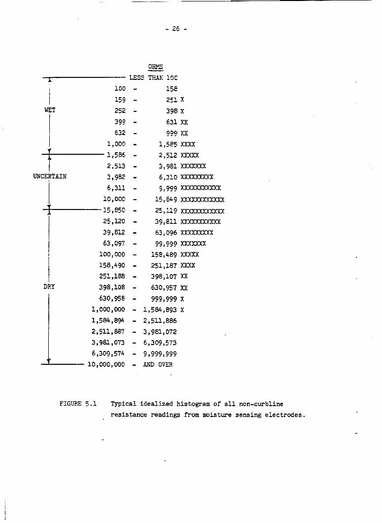
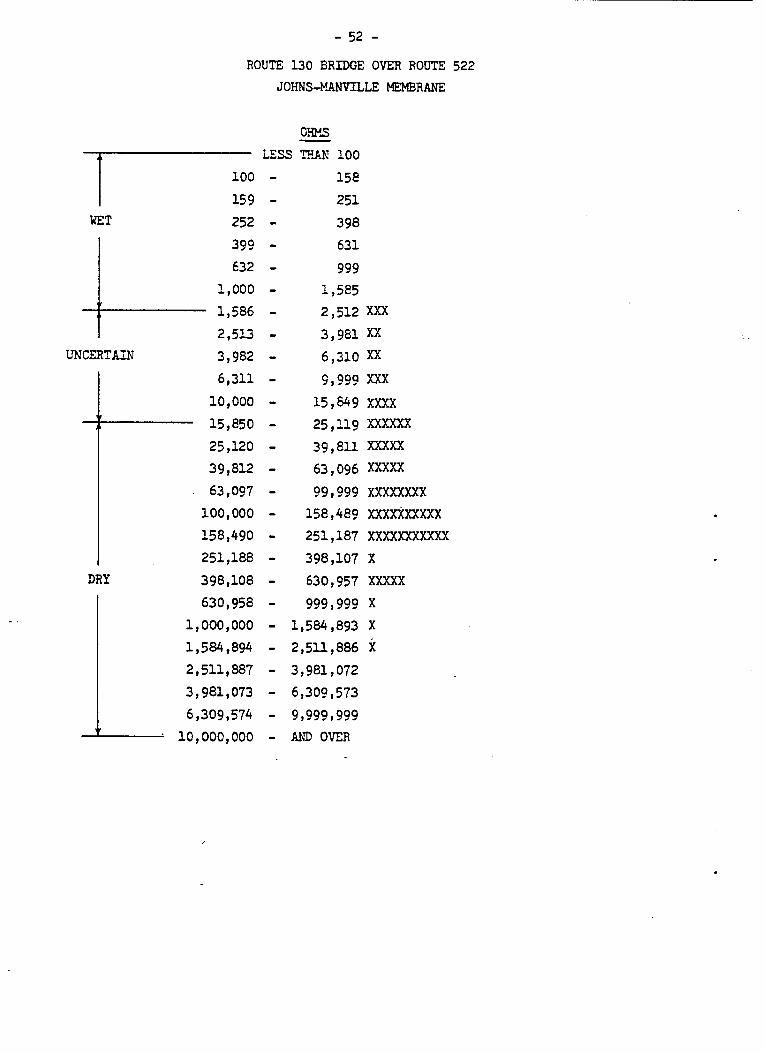
The moisture readings for several bridges are presented i n
Appendix 111. Because the res is tance readings vary from less than 100
ohm t o over 10,000,000 ohms, they have been plot ted on a log scale i n
order t o compress the range. One
format consis ts of simple histograms of all non-curb l i ne readings with-
out regard t o the dates on which the readings were taken. The second
format is similar except t h a t a time scale has been added i n an attempt
t o dis t inguish any long-term trends.
Two d i f fe ren t formats have been used.
F igure 5.1 illustrates an idealized histogram of res is tance readings
similar to those observed fo r several of the test bridges. These histo-
grams tend t o be centered i n o r close t o the "uncertain" zone wi th a
f a i r l y large percentage of the readings falling within the "uncertainff
zone.
F igure 5.2 is very similar to Figure 5.1 except that the points
a r e a l so located with respect to the length of time the mmbrane was i n
service when the readings were takel!. Like Figure 5.1, t h i s p lo t is
- 20 -
25,120 - 39,812 - 63,097 - 100,000 - 158,490 -
15E 251 x 398 X 631 XX 099 xx
1,%5 XXXX 2,512 xXXXx
3,981 XXXXXXX 6,31@ XXXXXXXXX 9,999 XXXxxxXXXXX 15 , 64 F XXXXXXXXXXXX 25 1x9 xxxxXXxxxXXx 39 , 811 XXXXXXXXXXX 63 , 096 XXXXXXXXX 99,999 XXXXXXX
158,489 XXXXX 251,187 XXXX
398,107 XX 630,957 XX
999,999 x 1,584,893 X
1,584,894 - 2,511,886 2,5111887 - 3,9e1,072 3,9819073 - 6,309,573 6 ,309,574 - 9 ??9?,9??
' 10~000,000 - AND OVER
FIGURE 5.1 Typical idealized histogram of a l l non-curbline resistance readings from moisture sensing electrodes.
I

- 27 -
LESS F'W 100 A
WET
i I I
100 - 159 - 252 - 399 - 632 -
1,000 - 1,586 - 2,5u -
T U N 3,982 - 6,311 - 10,000 - 15,850 - 25,120 - 39,812 - 63,097 - 100,000 - 158,490 - 251,188 -
Y 398,108 - 630,958 -
1,000,000 - 1,584,894 - 2,511,887 - 3,981,073 - 6,309,574 -
158 251 X 3 98 xx 631 X X X 999 XXXX
1,585 xx x xxx 2 , 512 X X X X x x 3 , 981 x x xx x x xxx 6,310 X X XXX XXX X X 9,999 x xx xx x xxx x 15,649 XX XXX X X X X 25,119 X XX XXX X X 39,811 X X 63,096 XX X X X X 99,999 x x xx x x
XX X X XXX
158,489 x x xx x 251,187 X XX X 398,107 X XX X 630,957 XX 999,999 x xx
1,584,893 2,511,886 X 3 , 981 072 6,309, 573 9,999,999
' 1O,OOO,OOO - AND OVER
FIGURE 5.2. Typical idealized plot of non-curbline readings from moisture sensing electrodes showing gradual drift toward wetter condition.

- 28 -
idealized t o c l ea r ly ind ica te a tendency tha t was observed on most of
the test bridges.
but, as the months p a s s , the range over which they are dis t r ibuted tends
t o d r i f t toward the " w e t " zone. Although t h i s tendency is noticeable on
nearly a l l of the test decks, i t is usually not as pronounced as the
idealized presentation shown i n Figure 5.2.
uncertainty of the amount o r source of the moisture beneath the membranes,
i t is not considered appropriate t o rate any of these membranes as
de f in i t e ly unsat isfactory a t t h i s time.
the decks are not drying out over a period of time and, because of the e f f e c t
t h i s may have on corrosion a c t i v i t y , there is a need f o r continued long-term
monitoring.
On any given date, the readings tend t o be scattered
Because of t h i s , plus the
However, it is qui te apparent t h a t
Another f a i r l y consis tent tendency was observed. I n many cases, the
readings from electrodes placed near the curbs tended t o be lower than
readings from s t r i p s near the center portions of the decks, suggesting a
greater presence of moisture near t h e gut ter . This may be an indicat ion
t h a t it is possible f o r water t o migrate around the edges of a membrane.
I n terms of ease of i n s t a l l a t i o n , the Maintenance forces who ins t a l l ed
the various membranes expressed a definite preference f o r the rolled-on
sheet systems (Royston, Grace, and Petromat). These systems require t h a t
the deck surface be smooth but the necessary preparatory work can be scheduled
whenever it is convenient over a period of several days p r io r t o the placing
of the membrane. I n a l l cases, these ins t a l l a t ions proceeded quickly and
e a s i l y using personnel wi th l i t t l e o r no previous experience.
Next in preference was the Johns-Manville system (asbestos-modified
This system has the added advantage tha t a smooth a spha l t i c concrete].

- 29 -
deck surface is not required but the higher-than-normal placement temperature
presents a po ten t i a l problem.
t o cool s u f f i c i e n t l y t o make placement d i f f icu l t .
Any unexpected delay could cause the mixture
The Uniroyal system (hot-applied l i q u i d ) also requires a smooth surface
and the i n s t a l l a t i o n procedure is somewhat more complicated than the others .
Both special heat ing equipnent and t ra ined personnel are required which
made t h i s system less a t t r a c t i v e t o the Maintenance un i t which normally
prefers t o use its own equipment and employees.
A s a r e s u l t of these preferences , the subsequent (non-experimental)
i n s t a l l a t i o n s have consisted of either the Royston o r Grace membranes.
(Because of its s imi l a r i t y , the Protecto-Wrap system is a l so permitted
but no contractor has elected t o use it. Although the Petrornat system
has appeared t o perform as well as t h e other test membranes, it has been
under test f o r a much shor te r period of time and has not y e t been approved
by our Design forces fo r non-experimental use.)
5 . 2 LATEX-EODIFIED CONCRETE AND LOW-SLUMP HIGH-DENSITY CONCRETE
These two systems are both very expensive and have been used only f o r
badly deter iorated decks f o r which the complete removal and replacement
of the upper 2 o r 3 inches of concrete was warranted. Once the low-slump
h i g h d e n s i t y concrete became available, contractors were permitted t o bid
on either system aEd the choice was then determined by the successful bidder.
A s described i n Sections 4 . 6 and 4.7, both systems require the same type of
preparatory work and both have experienced similar cracking problems d u r i n g
curing. Currently, both systems are considered ten ta t ive ly acceptable and
i t is expected t h a t addi t ional i n s t a l l a t ions w i l l be made.

- 30 -
5.3 EPOXY-COATED AND GALVANIZED REINFORCING STEEL - Epoxy-coating and galvanizing are systems designed to pro tec t the sur face
of the reinforcing steel and are used pr imari ly for new construction.
Design and Construction forces i n i t i a l l y preferred galvanizing because of
its re l a t ive ly low cost and ease of handling.
discouragement by the FHWA of further test in s t a l l a t ions of galvanized
reinforcing steel , t h i s preference has now sh i f ted t o the epoxy coating.
In our state, this is now the primary system chosen f o r new construction.
Our
However, because of t h e
1
5.4 INTERNALLY -SEALED CONCRETE
This is the only system included i n this study tha t d id not have a
Consequently, i t is s t i l l lengthy his tory of tests by other agencies.
regarded as very experimental and no fur ther i n s t a l l a t ions are planned a t
t h i s time,
6.0 DEPTH OF COVER STUDY
Since the depth of cover of the top mat of re inforcing steel is a major
fac tor i n preventing (or a t least delaying) the corrosive ac t ion of de-icing
chemicals, i t was decided t o conduct a satell i te invest igat ion of s eve ra l
br idges located throughout the state.
by means of a pachometer (nondestructive magnetic testing device) t o obtain
a large amount of statist ical d a t a which could be used t o pred ic t the
effect iveness of various possible depth of cover spec i f ica t ions .
A t o t a l of 17 bridges were surveyed
6.1 BASIC PREMISE
Although the nature of chloride penetration i n t o concrete is such that
i t is impossible t o define a spec i f i c depth below which t h e corrosion of
re inforcing s t e e l w i l l not occur, researchers have generally agreed t h a t
2 inches is an e f fec t ive minimum depth 899,10. The purpose of the satel l i te

- 31 -
study was t o determine what specified average o r target depth would be
necessary t o guarantee t h a t near ly a l l !or some specified , large percentage 1
o f t h e s teel would be below the 2 inch minimum depth.
6 . 2 EVALUATION OF THE PACHOMETER
The pachometer used f o r t h i s s tudy was a James Model C-4946. It consis ted
of a hand-held probe which was e l e c t r i c a l l y connected t o a b a t t e r y powered
u n i t provided with a d i a l gauge.
its depth of cover can be determined e i ther ( a ) d i r e c t l y from the d i a l o r
(b'l by reading a scale graduated from 0 - 100 and consul t ing c a l i b r a t i o n
curves furnished with the instrument.
When the size of a r e i n f o r c i n g bar is known,
I n o rde r t o ob ta in the greatest p rec i s ion f o r t h i s s tudy, a v a r i a t i o n
As the batteries gradual ly l o s t power, i t of t h e second method was used.
was observed t h a t the c a l i b r a t i o n curves should be s h i f t e d s l i g h t l y . As
a r e s u l t , i t became standard practice t o experimentally develop new cali-
b r a t i o n curves p r i o r to each day's use o f the instrument.
accomplished quickly and e a s i l y with a special f i x t u r e developed s p e c i f i c a l l y
f o r t h i s purpose.
This was
By having a number o f d i f f e r e n t ope ra to r s make many replicate readings
o f the depth of cover i n s p e c i a l l y prepared con t ro l slabs, i t was possible
t o determine the accuracy and p rec i s ion o f t h i s method.
found t o be accurate with a p rec i s ion o f W = 0.035 inches f o r s i n g l e
readings. This is the equivalent o f saying tha t single measurements
are accurate wi th in + 2 4 = 4 . 0 7 inches o r about +1/16 inch 95 percent
of the time. Consequently, i t was judged to be more than s u i t a b l e f o r
t h i s work.
The method was
- - -

- 32 -
6.3 DESCRIPTION OF TEST BRIDGES
The 17 test bridges were not a t r u e random s e l e c t i o n of a l l the bridges
i n the state but were chosen on the b a s i s of c e r t a i n practical considera-
tions such as accessibility and the ease of d i v e r t i n g t raff ic while the
measurements were being taken. However, an e f f o r t was made t o include
various shapes, s i z e s , and methods of construct ion (hand and machine f i n i s h e d ) .
Since the data was t o be used t o develop a s p e c i f i c a t i o n appl icable t o
cur ren t construct ion p r a c t i c e s , the decks selected were a l l comparatively
new, ranging i n age from a few months to about f i v e years .
O f the 1 7 test decks, nine were b u i l t w i th an earlier depth of cover
s p e c i f i c a t i o n of 1-1. inches w h i l e the remaining ei&ht had a specified depth
of cover of 2 inches. The earlier bridges were mostly hand f in i shed while
the newer bridges were l a r g e l y machine f in i shed .
w a s possible t o determine, the r e i n f o r c i n g steel was secured s i m i l a r l y f o r
a l l the decks.
and i t was the opinion of most of t h e construct ion personnel questioned t h a t
To the e x t e n t t h a t i t
No to le rances were given on the depth of cover s p e c i f i c a t i o n s
both s p e c i f i c a t i o n s were i n t e r p r e t e d as minimums.
6.4 ANALYSIS OF DEPTH OF COVER MEASUREMENTS
Depth of cover was measured a t approximately 40 systematic ( g r i d )
loca t ions on each of the test decks. Histograms f o r t h i s data from the
two sets of bridges are shown i n Figures 6.1 and 6.2.
Both d i s t r i b u t i o n s e x h i b i t a c e n t r a l tendency w i t h the means f a l l i n g
close t o the s p e c i f i c a t i o n values although, when statistical testa are
made, they are found t o be s i g n i f i c a n t l y d i f f e r e n t from the s p e c i f i e d
values. For the<earlier bridges (Figure 6.1) the mean depth is greater
than the specified depth which is w h a t might be expected if the specified

- 33 - OVERALL DISTRIBUTION INDIVIDUAL BRIDGE DATA
N = 398 X = 1.66"
0 = 0.33"
0-p 0.02" X
SPEC. DEPTH OF COVER (IN.)
MEAN (IN.) STD. DEV. (IN.)
1.75 - 0.19 1.27 0.23 1.31 1.88 1.63 1.79 1.72 1.74
1.87
0.22 0.24 0.27 0.20 0.25 0.27 0.28
FIGURE 6.1 Depth of cover over top steel of 9 New Jersey decks built with 1.5" specification.

- 34 -
OVER ALL DISTRIBUTION INDIVIDUAL BRIDGE DATA N = 314 MEAN (IN.) STD DEV. (IN.)
X = 1.84" I .88 0.4 8 CT -- 0.38" 2.04 0.3 7 0- = 0.020 2.24 0.2 I X
I .60 0.3 7 1.98 1.63 1.65 1.72
t SPEC.
DEPTH OF COVER (IN.)
0.24 0.30
0.20 0.1 8
FIGURE 6.2 Depth of cover over top s t e e l of 8 New Jersey bridge decks b u i l t wi th 2" spec i f ica t ion .

- 35 -
dep th were regarded as a minimum rather than a target value.
latter b r i d g e s (Figure 6.2 1 , however, the opposite s i t u a t i o n ex i s t s .
For the
bhen the depth of cover spec i f ica t ion was increased 'from If inches t o
2 inches, a corresponding increase i n the ove ra l l thickness of the deck
s l a b was also made. However, it is not known if the r e su l t i ng increase
i n dead load influenced the def lec t ion of the span i n a way t h a t would
a f f e c t the f ina l depth of cover over the top mat of reinforcing steel.
Although i t is not clear why these means should depart i n opposite
d i r ec t ions from the target values, the magnitudes of these departures are
not 80 great tha t the data cannot be used t o develop a useful depth of
cover spec i f ica t ion .
contractor i n setting the s t e e l e i t h e r too high o r too low, it is believed
t h a t t he departure of the mean from the specif ied value w i l l be essent ia l ly
zero, on the average, espec ia l ly if the specif icat ion has equal p l u s and
minus tolerances which are enforced.
Since there seems t o be no obvious benef i t t o the
Since the histograms are approximately normal, the d i s t r ibu t ion of
depth of cover w i l l be assumed t o be normal for purposes of developing
the specif icat ion.
values i n Figures 6.1 ar?d 6.2 may r e f l e c t a real i n a b i l i t y on the part
of the contractor t o control the mean depth of cover on a given bridge,
t h i s w i l l be taken i n t o account by combining these two sets of data rather
than s imply pooling the standard deviat ions.
common basis, each data value w i l l be coded by subtract ing the specif ied
value.
zero ( ind ica t ing that, on the average, the depth of cover w i l l be as
spec i f ied) and a standard deviat ion of 0.38 inches.
Since the departures of the means from the specified
I n order t o es tab l i sh a
This produces an approximately normal d i s t r ibu t ion wi th a mean of
- 36 -
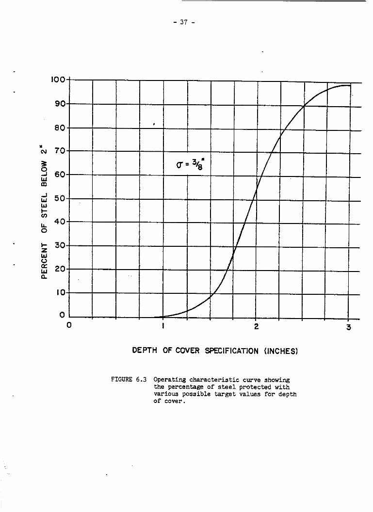
6.5 DEVELOPMENT OF A DEPTH OF COVER SPECIFICATION
This standard deviat ion, which represents the v a r i a b i l i t y of t he
depth of cover about the specified value, is approximately 3/8 of an
inch and is used t o construct the operating characteristic curve shown
i n Figure 6.3. This curve gives the percentage of steel protected (depth
greater than 2 inches) by various possible depth of cover s p e c i f i c a t i o n s .
For example, t h i s curve indicates that a spec i f ied depth of cover of
26 inches would be expected t o pro tec t approximately 90 percent of the
steel. If i t were desired t o keep near ly a l l of the steel be& a depth
of 2 inches, a specified depth of 3-1/8 inches would be required.
Once a s u i t a b l e target value has been decided upon, appropriate
p l u s and minus tolerances m u s t be added t o complete the s p e c i f i c a t i o n .
Idea l ly , a s ta t is t ical survey of the l e v e l of top s teel f o r s e v e r a l
bridge decks just p r i o r t o the placereent of concrete would determine
w h a t degree of compliance could reasonably be expected. I n the absence
of such a survey, f i e l d experience and engineering judgement m u s t be
relied upon. Realizing t h a t the v a r i a b i l i t y of the l e v e l of the steel
before the pour would be expected t o be less than after the pour, and
considering t h e r e l a t i v e ease of cor rec t ing s teel t h a t is improperly
placed, i t is suggested that +1/4 inch would be a reasonable tolerance
f o r the s e t t i n g of the steel.
-
As a direct result of t h i s s tudy, the s p e c i f i c a t i o n f o r depth of
cover i n New Jersey has been increased although i n a s l i g h t l y d i f f e r e n t
form from tha t recommended here. The previous s p e c i f i c a t i o n required a
minimum depth of cover o f 2 inches.
inches.
This has now been increased t o 23
- 37 -
DEPTH OF COVER SPECIFICATION (INCHES)
FIGURE 6.3 Operating characteristic curve showing the percentage of s t e e l protected with various possible target values for depth of cover.

7.0 REFERENCES
1. Lindberg, H . A . , "Use of Galvanized Rebars i n Bridge Decks , I '
FHWA Notice N 5140.10, July 9, 1976.
Federal Highway Program Manual, Volume 6 , Chapter 7 , Section 2,
Subsection 7, 1976.
2.
3. Bergren, J. V., "An Evaluation of Concrete Bridge Deck Resurfacing
I n Iowa," Iowa Department of Transportation, 1975.
4 . White, R. O . , VEEP No. 16 - Epoxy Coated Rebars, Summary of Costs
and General Comments," FHWA, Ju ly 19, 1974, Memorandum.
5 . Clear, K. C. and Fors te r , S. W . , l l Internal ly Sealed Concrete:
Yiterial Characterization and Heat Treating Studies," Interim
Report, March 1977.
6. Federal Highway Administration, "Internal ly Sealed Concrete,"
User's Guide, A p r i l 1977.
7. Review Team, Bureau of Construction and Compliance Prac t ices ,
New Jersey Department of Transportation, "In-Depth Inspection of
Wax Impregnated Concrete Bridge Decks - Stage I and S ta t e 11,"
two reports , 1977.
8. Portland Cement Association, IlDurability of Concrete Bridge
Decks, 1970.
9. NCHRP Synthesis of Highway Pract ice No. 4 , Voncrete Bridge Deck
Durabili ty ,11 1970.
10. Maloney, M. F . , "FHWA Ins t ruc t iona l Memorandum 40-6-72, 1972.
- 39 -
APPENDIX I
SPECIFICATIONS FOR MOISTURE SENSING ELECTRODES

- 40 -
Copper Tape
Scotch Brand No. X-1181 copper tape wi th pressure sens i t ive conductive
aehesive, 3 inch wide by 0.0015 inch th ick , obtainzble from:
Minnesota Mining & Manufacturing Go. 5698 Rising Sun Avenue Philadelphia, PA 19120
Polyethylene Tape
No. 357 Nashua polyethylene laminated cotton c lo th tape with pressure
sens i t ive adhesive on c lo th side, 2 inches wide, obtainable from:
Ridgewood Corporation Nashua Corporation 58 F i f t h Avenue or Dutch Brand Division Hawthorne, N J 07507 44 Franklin Street
Nashua, NH 03060
Wire Leads
High temperature insu la ted copper wire, 18 gauge, stranded, 7 s t r ands ,
t inned, temperature rating 2OO0C, S.R. Style 3135, obtainable from:
Radix Wire Co. 26260 Lakeland Boulevard Cleveland, OH 44132
(NOTE: 18 t o 25 gauge and 7 to 17 s t rands acceptable. 1

- 41 -
APPENDIX I1
MOISTURE SENSING ELECTRODE LOCATIONS

- 42 -
JOHNS - MANVILLE MEMBRANE
Rt .130 BRIDGE OVER PENNA. R.R.
Bridge* 1227155 Membrane installed 7/12/72
No. 102 Torn durinq construction - approx. the first 2' i s intact.

- 43 -
JOHNS - MANVILLE MEMBR'ANE
R t . 13.0 BRIDGE OVER 522
BridgeR I2271 56 Membrane installed 7/14/72
NORTHBOUND TRAFFIC -
- SOUTHBOUND TRAFFIC +
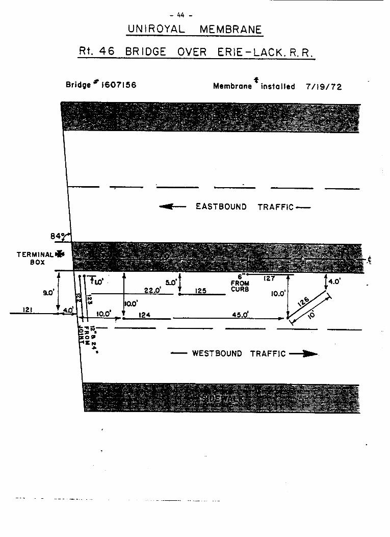
- 44 - UNIROYAL MEMBRANE
R i . 46 BRIDGE OVER E R E - L A C K . R . R .
Bridge # 16071 56 Membrane x insta l led 7/19/72
i
EASTBOUND TRAFFIC -
- WESTBOUND TRAFFIC

- 45 -
UNIROYAL MEM6RANE
R t . 4 6 BRIDGE OVER PAULISON AVE.
Bridge 1607158 Membrane installed 7/19/72.
EASTBOUND TRAFFIC -
- WESTBOUND TRAFFIC

- 46 -
ROYSTON AND GRACE MEMBRANES
PRINCETON JUNCTION BRIDGE W.8. ( fa- PRINCETON
* 0 \
TERMlNAL BOX ' Flo-3'd45.4. ,
10.8' I
k- 65.2' -
PRINCETON - S I DLWAL K
Measurements from end of metal curb and expansion joint.
PRINCETON JUNCTION BRIDGE E.B. ( to HIGHTSTOWN 1
Measurements from end of metal curb and exponcion joint.

- 47 - ROYSTON AND GRACE MEMBRANES
TERMINAL BOX
rE
@
2' f t=
I
- 30' -1 5 2 ' 1
-Rt. 17 NORTH - 11/7/73
ROYSTON MEMBRANE
- Rt.17 SOUTH * 11/8/73
GRACE MEMBRANE - @ - - 49 -
R t . 1 7 BRIDGE OVER N.Y.S. 8 W . R . R .
BRIDGE # 0214158

- 48 -
PETROMAT. MEMBRANE
R t . 70 BRIDGE OVER CENTRAL .R.R.
BRIDGE# 1509152 Membrane instal led 8/8/75
C E N T E R D I V I 0 ER . . . . . . . . . . . . . . . . . . . . . I
r0 If'
EASTBOUND TRAFFIC ___t
f :
9'
I -@
14' 7 I@ I
I?. 5 '
- 32 ' /
L 49' 1c - 57.5' c
Wires to No.7 were severed during placement of the overlay.

- 49 -
A P P E N D I X I11
MOISTURE S E N S I N G ELECTRODE READINGS
HISTOGRAMS AND TREND P L O T S

- 50 - ROCTE 130 BRIDGE OVER PRR
JOHNS-MANVILLE MEMBRANE
I WET
100
15 9 252 399 632
1 , 000 1 , 586 2,5U 3 , 982 6,311 10 1 DOC
UNCERTAIN
DRY
1 25 , 120 39,812 63 097
100,000 158,490 251 188 398 , 108 630,958
1,000 , 000 1,584 , 894 2 , 511,887 3,9811073 6,309,574 10 1 000 , 000
15E
251 398 €31
999 1,585 2 , 512 3 1981 6,310
9 1999 15,&9 25 , U? 39 ,811 63,096 99 1 999
158 489 251 , 187 398,107 630,957 999 1 999
1,584 2,511 3 1981 6,309
893 886 072 573
9 1999 1999 AND OVER
X xx xx X xx xxxx xXXXXxxxxxx xxxxxxxxxxx xxxxxx xxxxx xxxxxxxxxxx xxxxxxxxxx xxxxx XXXXXX XXX xxxx xxxx X
X

- 51 -
- LESS THAN 100
158 251 -‘I WET 252 1 - 398
399 - 63 1 632 - 999
1,000 - 1,585 1,586 - 2 , 512 2,513 - 3,981
6 , 310 6,311 - 9 ,999 10,000 - 15 , 849 15,850 - 25 , 119 25,120 - 39 , 811 39,812 - 63 , 096 63 , 097 - 99,999
UNCERTAIN L 3,982 -
100,000 - 158,489 158,490 - 251,187 251,188 - 398,107
DRY 398,108 - 630,957 630 , 958 - 999 9 999
1,000,000 - 1,584,893 1,584,894 - 2,511,886 2,511,887 - 3,981,072 3,981,073 - 6,309,573
r 6,309 1 574 - 9 ,999,999 10,000,000 - AND OVER
1 2 1
23 4
3 5
3 26 34134 6 6 3 4 2 4
3 3 3 l6 1 26 6 3 34
1 3 4 4 6 266 6 5 5
24 5 2 1 1
6 4 3 3 1
2 6 2 4 4 4 1 3 5 5 2 2 4 5 6
6 5 5 Z 5 2 6 1 5
1 1 24 5 1 1 5
5
5
(Numbers i den t i fy e lec t rode locations)
- 52 -
6,311 - 9,999 xxx 10,000 - 15,649 XXXX
7,
I I 15,850 - 25,119 XXXXXX
25,120 - 39,811 XXXXX 39,812 - 63,096 XXxxx 63,097 - 99,999 XXXXXXXX 100,000 - 158,489 XXXXXXXXXX 158,490 - 251,187 XXXXXXXXXXX 251,188 - 398,107 X
ROUTE 130 BRIDGE OVER ROUTE 522 JOHNS-EAANVILLE MEMBRANE

- 53 -
399 - 632 -
1,000 - 1,586 - 2,513 -
6,311 - 10,coo - 15,850 - 25,120 - 39,812 - 53,097 - 100,000 -
251,188 - C3Y 398,108 - L I,coo,ooo 630,958 - -
1,584,294 - 2,511,887 - 3,981,073 - 6,309,574 -
L'KCERTAIW c 3,982 -
1 10,000,000 -
153,490 -
631
999 1 , 585 2 , 512 3 , 981 6,310 9 ,999 15 ,849 25 119 39 , 811 63 , 096 39 ,999 158 I 489 251 , 187
398,107
4 l4
4 3 4 4 2
3 23 2 2 3
1 34
4 23 1 3 3 1
3 23 1 2 1 2 2 3 4 4 2 1
23 3 3 2 2 3
630 , 957 4 4 1 2 1
999 I999 1 4 1 1 584 1 833
1 2 , 511,886 3,981 , 072 6,309,573 9 1 999,599
O E R
(Numbers i d e n t i f y electrode locztions 1

- 54 -
6,311 - 9,999 XXXXXXX
10,000 - 15,849 XxxxM( I
I I 15,e50 - 25 , 119 XXXX 25,120 - 39,811 XXXXXX
39,812 - 63,096 XXX 63,097 - 99,999 x 100,000 - 158,489 XXX 158,490 - 251,187 25i,l= - 398,107
ROUTE 46 BRIDGE OVER ELRR UNIROYAL MEMBRANE
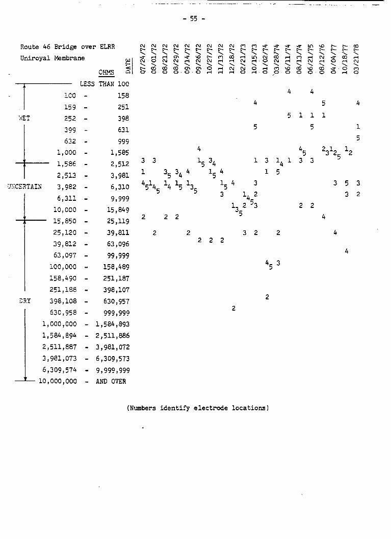
- 55 -
io L:S THAN 100
158 159 - 251
:*;E T 252 - 308 3Q9 - 63 1
632 - 999 1,000 - 1 , 585 1,586 - 2 , 512 2 , 5 u - 3 , 981
6 , 310 6,311 - 9 ,999
10,oc0 - 15 1 %? 15,850 - 25,119
UXCE2TAIN k 3,982 -
4 4 4
5 1 1 5 5
45 4 1 3 1 4 1 3 3 34
1 35 34 1 5 3 3
3 1, 2
45145 135 3
2 2 2
'5 1, 2 3
25,120 - 39 , 811 2 2 3 2 2 39,812 - 63 , 096 63,097 - 99 1999
2 2 2
100,000 - 158,489 45 158,490 - 251,187 251,188 - 398,107
CRY 398,108 - 630,957 630 1958 - 999 ,999
1,000,000 - 1,5844,893 ll584,e94 - 2,511,886 2,511,887 - 3,981,0172 3,981,073 - 6,3099573 6,309, 574 - 9 ,9991999 i 10~000,000 - AND O'ER
2 2
2 2
5 4
1 1
5 2 1 l2
25
3 5 3 3 2
4
4
4
(Numbers ident i fy electrode locations 1

- 56 - ROUTE 46 BRIDGE OVER PAULISON AVE.
UNIROYAL MEMBRANE
100
15 9 WET 252
399 632
1 , 000 1,586 2,5U
UKCERTAIN 3,982 6,311 - 10,000 - 15,850 - 25,120 - 39,812 - 63,097 - 100,000 - 158,490 - 251,lM - 398,108 -
I 630,958 - DRY
158 X
xxxxx xxx xxxx Xxxxx xxxxxxxx xxxxxxxxxxxxxx XXXXXXX
XXxxxXX xxxx xxxx xxxxxxxxx XxXxxxX XxxxXX XXXX xxxxx
630,957 XX 999,999 xx

t;' m 3
P 0 c)
P O m w N P P
W N ul P 07/24/72
w - c . N ul P 08/01/72
08/21/72
W f - N P 08/29/72
09/14 /72 w N u l P
N u l P 09/26/72
10/27/72
N u l P 11/13/72
r u e P 12/18/72
C u l P 02/21/73
u l * N P 10/15/73
ru t-. 01 /02 /74
U I f - N P ' 03/28/74
* N P 06/11/74
(u C P 08/13/74
06/21/75
08/12/76
f-
P ul
ul
w f - N
f-
f- W
W N ul P c.
f- W
ul W
W N
W
W f - u l
W
W
ul
ul
ul w f - N P
f- P W N ul
I
w
f-
f-
P N u l W
W P N u l
04 /04 /77 10/18/77
03/21/78 W U I f - *N P

- 58 -
6,311 - 9,999 x
l i 15,850 - 25,119 X
10,000 - 15,649 xx I f
25,120 - 39,8U KXXX 39,812 - 63,096 XXXX 63,097 - 99 1 999 100,000 - 158,489 158,490 - 251,187 251,188 - 398,107
PRINCETON JUNCTION BRIDGE WESTSOUND ROYSTON MEMBRANE
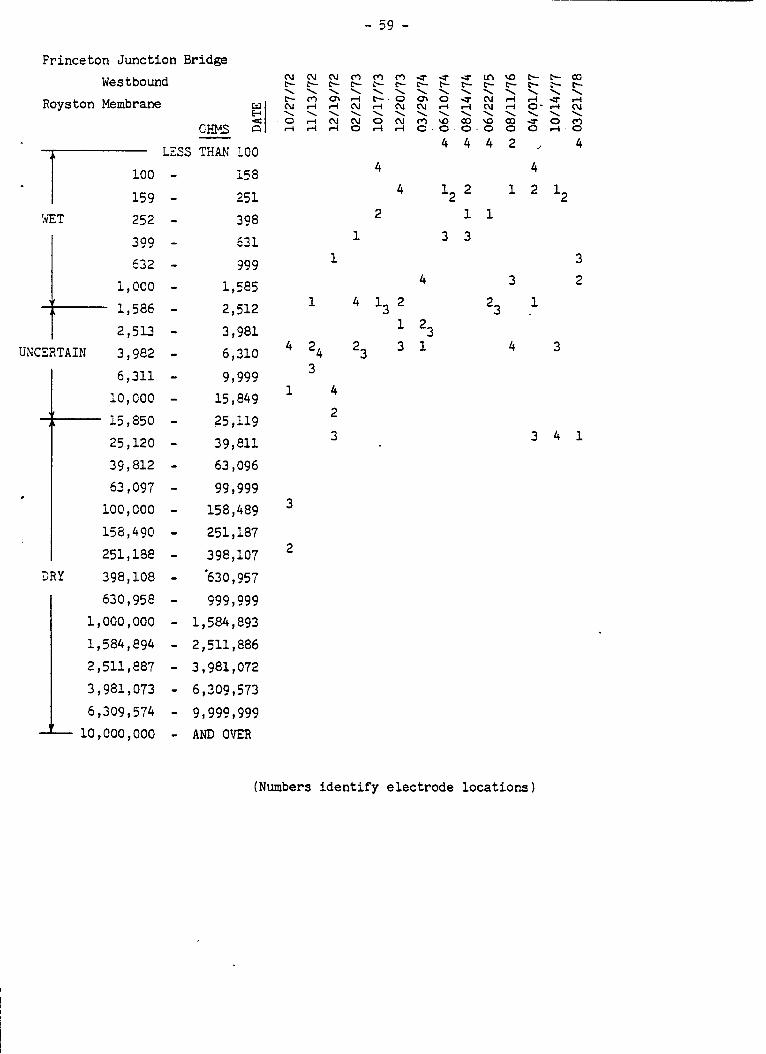
Princeton Junct ion Bridge Westbound
Royston Membrane
cws
N N N c - c - c - \ \ \ c - - o m N d r l \ \ \ O r l N r l d r l
LtSS THAN 100 100 - I 15 9
!vE T 252 399 632
1 1 000
I
1 586 2 , 5 u
UNCERTAIN 3 982
6,311 10 1 000
3 R Y
25 120 39 812 63 097 100,000
156,490 251 188 398 108 630 958 000 pooo 584 894 511 e87 981 073
6,309 A L 10,000
5 74 000
i58 251
398 53 1 999
1,585 2 512 3 981 6,310
9 1999 15 849 25 119 39,811 63 , 096 99 1999
158 4a9 251 187 398,107 '630 957 999 1999 584,893 511 , 886 981 072 309 573
9 1990 1999 AND OVER
1
1
24 3
1 4 2 3
3
2
- 59 -
3 1 23
r? c-. \ rl cu \ cu 0
1
4
m L- \ c- rl \ 0 rl
4
2
13 23
4
l2 4
1 3 3
L3
w c- \ rl rl \ a2 0
2
1
3
4
3 2
1
3
3 4 1
(Numbers i d e n t i f y electrode locations)

- 60 -
I \ 15 , e50 25,120 39,812 63 , 097 100,000 158,490 251,188
PRINCETON JUNCTION BRIDGE EASTBOUND GRACE MEMBRANE
O M - LESS T???3 100 XXXXXXXXXXX
15e XXM. 251 xxxxxx -7 -
159 - k'ET 252 - 398 XXX
399 - 631 XX
632 - 999 m x x 1,000 - ll5E5 xx 1,586 - 2,512 xx 2,5U - 3,981 XXXX
lRZCERTAIB 1 3,982 - 0,31@ X 9,999 xxxx 15,w9 x ZpU? XXX 39,811 XX
63 , 096 99,999 XX 158,485 251 , 187 398,107 630,957 999 1 999
1,584,893 2,5ll, 886 3,981,072 6,309,573 9,999,999 AND OVER XXXX
,

- 61 -
Princeton Junct ion Bridge
Eastbound w 51 Grace Merrbrane
CHIAS p.
LESS THAN 100 i58 251
-
-.E - ;,z -'p L 252 1 - 398 3?? - 531 632 - 999
1,OGO - 1,585 1,586 - 2,512 2,5U - 3,981
6,210 6,311 - 9,999
10,GOO - 15,849 12, 850 - 25,119
K:CZZTAIN t 3,982 -
25,120 - . 39,811 39,812 - 63,096 63,C97 - 99,999 100,000 - 158,489 158,490
* 1 251,188 2 3Y 398 , 108
630,958 1,000,000 1,584,894 2,511,887 3,981,073 6,309 , 574 1 10, COO, 000
251,187 398,107 630,957 999,999
1,584,893 2,511,886 3 ,981,072 6,309,573 9 , 999,999 am OER
3
4 4 4 4
4
c
(Numbers identify e lec t rode locations 1

- 62 - ROUTE 70 B R I D G E OVER CRR
PETROPAT EMBRANE
I 15 9 h'ET 252
3 9? 632
1 , 000 1 , 586 2,513 3 , 982 6 , 311 1c , 000
l i - 15,850 25 , 120 39 , 812 63 , 097
1oc , 000 159,490 251 , 188
DRY 398 , 108
UNCERTAIN c 1 1
251 398 631 ??9
1,515 xxX 2,512 XXX 3,981 XX
6,310 XX
9,999 x 15,849 25 , 119 39 , 811
63,096 XX 99,999 xx
158,48? X 251,187 X 398,107 XX
630,957 XX
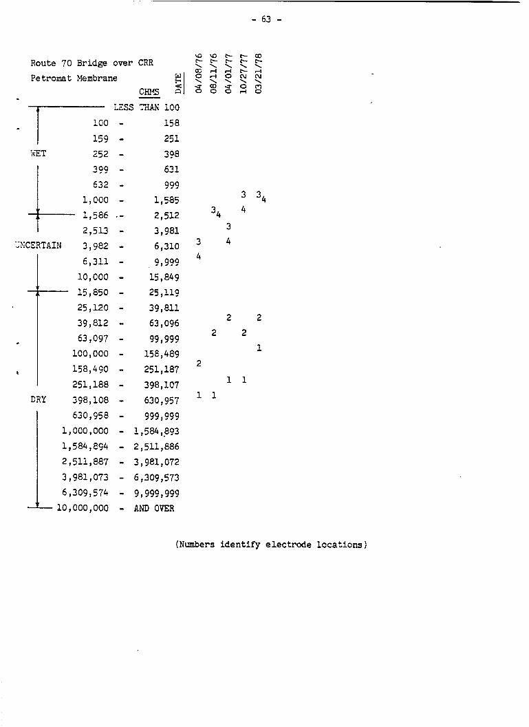
Route 70 Bridge over CRR
Pe tromat Membrane 51 O H r S 3,
LESS TIdAii 1CO 158
251
-
-'Tg ;:;ET 252 - 1 308 399 - 63 1 I 632
I, 000 1,586 2,5U
6,311 10,000
X C E R T A I N 3,982
15,850 25,120 39,812 63,097 100,000 158,490 251,188
CRY 398,108 :~ 1,000,000 630,958
c
1,584 , 894 2,511,887
3,981,073 6,3099 57' 10,000,000
999 I, 585 2,512 3,981 6,310
9,999 15,849 25,119 39,811 03,096 99 1999 158,489 251,187 398,107 630 , 957 999,999
2,511, E86 3,981,072
6,309,573 9,999,999
1,584,8?3
AND OgER
- 63 -
34 4 34
3 3 4 4
2 2 2 2
1 2
1 1 1 1
(Numbers identify electrode locations 1
- 64 -
APPENDIX I V
IDENTIFICATION OF TEST BRIDGES
,

- 65 -
APPENDIX I V
LIST OF TEST BRIDGES
SYSTEM PROJECT OR BRIDGE INSTALLATION
- SYSTEM IDENTIFICATION DATE COMMENTS
Johns-Manville Route 130 7/12/72 Weather clear and d ry , Asbestos Structure 1227155 temperature i n 80's f o r Modified (over Penn. R.R . ) both i n s t a l l a t i o n s . Asphalt Barber-Greene paver, Membrane metal tracks. Mix had
15% asphal t , 6% asbestos . Small amount of material
Route 130 7/14/72 on second bridge (over Structure 1227156 Route 522) was not corn- (over Route 522) p l e t e ly mixed.
Uniroyal Route 46 711 9 172 Hot Applied Structure 1607156 Liquid (over Erie-Lack- Rubberized awanna R . R . ) Asphalt Membrane
Route 46 Structure 1607158 (over Paulison Ave. 1
Ins t a l l a t ion was made a t night, weather was clear and d r y with the tempera- ture i n the 70's. The o u t l e t valve f o r the special heating ket t le began t o clog during the treatment of the second bridge (over Paulison Ave. 1 but the wgrk was completed s a t i s f a c t o r i l y .
Roys ton Route 64 Westbound 10/16/72 Ro 11 ed -On Structure 1117150 Preformed ( t o Princeton over Sheet Penn. R . R . ) Membrane
Route 17 Northbound 11/7/73 Structure 0214158 (over M.Y. and Western R .R. 1
Weather w a s windy and f a i r l y dry w i t h tempera- tures i n the 50's. A metal-tracked paver was used but d id not damage the membrane.
The weather w a s dry and cold f o r t h i s installa- t i on , temperature i n t h e 30's.
P h i l l i p s Route 70 8/8/75 Weather w a s clear and dry Fabr i c & Tack Structure 1509152 w i t h temperatures i n the Coat Membrane (over Central R.R . 1 60 Is. The i n s t a l l a t i o n (Petromat) proceeded smoothly except ,
due t o a shortage of sealer emulsion, an 18 inch wide gap next t o the center d iv ider i n the eastbound lane received no membrane.

- 66 - S Y S T E M
PROJECT OR BRIDGE INSTALLATION S Y S T E M IDEhTIFICATION DATE COMMENTS
W. R. Grace Route 64 Eastbound 10/1?/72 Weather was p a r t l y cloudy Rolled-On Structure 1117150 with temperatures i n the Preformed ( t o H i g h t s t o w n , 60's. The deck was w e t Sheet over Perm. R.R . ) early i n the morning but Membrane dry before the membrane was
installed. The membrane was deeply marked but not cu t by the metal-tracked paver. Several vapor bubbles formed under the membrane which had t o be punctured and repaired.
Route 17 Southbound 11/8/73 Structure 0214158 iover N.Y. and Western R . R . )
Route 46 1975 Structure 0202150 (Homestead Ave . I
Route 46 19-75 Structure 0202151 (Brinkerhoff Ave . I
Route 46- 1975 Route 63 Westbound Structure 0202156 (Bergen Blvd. 1
Route 46 1975 Structure 0202 158 (Main St . 1
The weather was dry and cold fo r t h i s i n s t a l l a t i o n , temperatures i n the 30's.
Route 1-80 1975 Rockaway, NJ (Total 24 decks)
DOW S M - 1 0 0 (Renamed Kecrny Ave. Bridge 11/12/75 Modifier A ) Structure M6561001 Latex (over Erie-Lack- Modified awanna R . R . ) Concrete #
Dorset Ave. Bridge 1976 (Atlant ic County 1
Weather was cool and damp f o r much of t h i s work. Subsequent cracking problems developed. Details are discussed i n Sect ion 4.6 of t h i s repor t .
Weather was cool with slight amount of r a i n , d i d not delay work.

- 67 - SYSTEM
PROJECT OR BRIDGE IPJSTALLATIOW COMMENTS - SYSTEM IDENTIFICATION DATE
DOW SM-100 Route 1-287 North- 1976 (Continued 1 bound
(over L i t t l e t o n Rd. 1
Route 1-287 North- 1976 bound (Over Route 461
Low-Slump High-Density
Mountain Ave. 5/13/77 Bridge Somerville, N J (over Pe ter ' s Brook)
Po t t e r sv i l l e Rd. 6/20/77 Bridge Peapack, N J
Lanington Rd. Bridge
Concrete Iowa Sys tem 7/26/77
Pascack Rd. 8/8/77 Bridge
These ins t a l l a t ions were witnessed by personnel from the Bureau of Con- s t ruc t ion Pract ices who reported t h a t numerous micor d i f f i c u l t i e s were encountered and eventu- a l l y overcome as the construction forces became more familiar with the procedure. Further d e t a i l s a re contained i n Section 4.7 of t h i s report .
~ -
EPOXY Route 1-295 Bridge 1974 For the northbound deck, Coated (over E. S t a t e S t . a l l re inforcing steel was Reinforcing Trenton, N J ) coated including the para- Steel p e t steel. For the south-
bound deck, the bottom m a t was not coated. Tie wires were coated, chairs were galvanized. The e p a y coated bars had many nicks and minor defects which required f i e l d touch-up .
Routes 1 & 9 1975 Both upper and lower mats over Route U.S. 22 (Express 1 were galvanized. T i e wires Structure 0702151 1976 and chairs were not gal-
(Local) vanized . Route 495 over Routes 1 & 9 Structure 0917150 Route 29 over 1976 Both upper and lower mats Alexauken Creek were galvanized. Structure 1007153
Both upper and lower mats 1976 were galvanized. Galvanized
Reinforcing Steel

- 68 - SYSTEM
PROJECT OR BRIDGE INSTALLATION SYSTEM IDENTIFICATION DATE COMMENTS
Galvanized Routes 1 & 9 over 1976 Both upper and lower mats Reinforcing Route U.S. 21 were galvanized. Steel Structure 0702153
In te rna l ly Heller Parkway 12/6 /76 This system is the most . Sealed Bridge experimental of those Concrete (over Erie-Lack- included i n t h i s s tudy ,
awanna R.R. , Both i n s t a l l a t i o n s were Nswark, NJ) witnessed by personne 1 Eastbound from the Bureau of Con-
s t r u c t i o n Practices who Heller Parkway 5/12/77 have wri t t en a lengthy Bridge report8 descr ibing t h e (over Erie-Lack- work i n d e t a i l . A b r i e f awanna R.R. , Newark, N J ) Westbound
summary is presented i n Sect ion 4.10 of t h i s report .
APPENDIX V
DESCRIPTION OF AN INSTALLATION
OF LATEX-MODIFIED CONCRETE

- 70 -
On August 13, 1971, the writer witnessed the resurfacing of a bridge
deck wi th a new system developed by Dow Chemical Company.
bridge is located i n Delaware on the off-ramp t o southbound Routes 13 & 40
innnediately a f t e r crossing the Delaware Memorial Bridge.
This experimental
This pa r t i cu la r system is designated SM-100 and cons is t s of a l a t e x
modified mortar mix which is claimed t o produce concrete which is s t ronger ,
more f l e x i b l e , more impermeable, 2nd more r e s i s t a n t t o chemical a t t ack
than conventional concrete . Prior t o placing t h i s mix on the deck , the surface of the old concrete
is removed by means of a power scarifier t o whatever depth is necessary t o
get down t o so l id concrete.
spa l l ed areas i t is of ten necessary t o go deeper.
some hand chipping around and below the reinforcing steel.
After the de ter iora ted concrete has been removed, the e n t i r e deck
Usual ly t h i s is one inch or less, but i n
This frequently requi res
(and espec ia l ly any exposed reinforcing s teel) is sandblasted t o
thoroughly clean t h e scarified surface. If necessary, badly rusted
reinforcing bars are replaced.
Just p r io r t o the ac tua l paving, the bridge deck is f lushed wi th
water t o remove any residual d i r t and debris and a l s o to provide a moist
surface f o r proper bonding of the mortar.
The placing of the SM-100 material is accomplished by a "paving t r a i n "
designed by Dow and operated under t h e i r supervision.
cons is t s of an automatic batching truck (Concrete Mobile) followed by a
The "paving t r a i n "
f in i sh ing machine.
the batching t ruck d i r e c t l y onto the deck a t a uniform rate by swinging
the discharge chute back and fo r th . Laborers then move i t w i t h shovels
and brooms so that i t is spread f a i r l y evenly ahead of the f in i sh ing
An operator continuously deposi ts t he mortar mix from

- 71 -
machine which strikes it o f f smoothly a t the desired l e v e l . F i n a l
f i n i s h i n g operat ions are done by hand and include "gently" broom
f in i sh ing . Curing is accomplished by coveringwithBurlene (bu r l ap faced
wi th polye thelene I w i th in one hour af ter placement.
A Dow engineer a t the job s i te explained that the "paving t r a i n "
approach wi th the automatic batching t ruck was required t o achieve the
necessary q u a l i t y c o n t r o l . Earlier tests by varying procedures i n
d i f f e r e n t states had not produced c o n s i s t e n t r e s u l t s . He reported t h a t
there were now f i v e Dow "paving t r a i n s " i n ope ra t ion throughout the
country which have made many success fu l i n s t a l l a t i o n s , s e v e r a l of them
i n Michigan.
The Dow li terature gives the fol lowing mix proport ions f o r the
l a t e x modified mortar:
Cement.. .............. 94 lbs. (1 bag3
Sand.. ................ 3.25 cu. f t .
Latex.. ............... 3.5 gal.
Water.. .............. .As requi'red f o r water-cement r a t i o o f 0.35 t o 0.40.
The Don engineer stated t h a t the cement f a c t o r is q u i t e high, around
e ight bags per cubic yard. He a l s o said tha t a i r content is usua l ly con-
t r o l l e d between 6% t o 9%. When asked the same ques t ion , the foreman on
the job mentioned 5% t o 7% as the usual range. The Dow s p e c i f i c a t i o n s
s imply state Itnot more than 10% en t r a ined air." The a i r content o f the
material being used a t the Delaware s i te w a s 54% as determined wi th a n
Acme a i r meter.
This p a r t i c u l a r job was o r i g i n a l l y scheduled t o begin a t 6 a.m.,
apparent ly because the material is heat s e n s i t i v e and may set up too

- 72 -
fast. The weather forecast changed, cooler temperatures were predicted,
and the work w a s rescheduled t o start a t the usual time. The paving
was nearly complete by noon a t which t i m e the air temperature was
approximately 80°. The mortar mix i tself was a t a temperature of 70'
when placed and rose t o 7 3 O after one hour.
I
- 73 -
APPENDIX VI
DEVELOPMENT OF ECONOMIC EQUIVALENCE CHARTS

- 74 -
BACKGROUhQ
A very expensive protective system may be more cos t e f f ec t ive than a
less expensive system provided it has a correspondingly longer expected
l i f e .
t o evaluate them on some common b a s i s .
essent ia l ly equivalent f r o m a performance standpoint throughout t h e i r use-
f u l l i ves , the most log ica l bas i s of comparison is an economic one.
I n order t o compare drastically d i f f e ren t systems, i t is necessary
Assuming that the systems are
When first installed, the less expensive system has 2 clear economic
advantage s ince i t provides equivalent protection a t a much lower cos t .
However, because the less expensive system has a shor te r useful l i fe , i t
must be replaced periodically.
i n i t i a l economic advantage and, depending upon the frequency of replacement,
the more expensive system may turn out to be the more cos t benef ic ia l one
in the long run.
This ext ra expense may outweigh the
BASIC ECONOMIC CONCEPT
For convenience, the less expensive system w i l l be referred t o as
System 1 and the more expensive system as System 2.
comparison, the t o t a l value a t any time of System I must include the
growth (a t compound i n t e r e s t ) of the amount of money saved by not s e l ec t ing
System 2. However, the periodic cos t ( including i n f l a t i o n ) of replacing
System 1 must be paid f o r f r o m t h i s principal and, under most normal
conditions, the pr inc ipa l w i l l eventually be deple ted in t h i s manner.
Consequently, after a spec i f i c length of time, the value of System 1
w i l l become zero. If the useful l i fe of System 2 were t o be exact ly
equal t o this length of time, the two systems would be considered t o be
equivalent from an economic standpoint. Therefore, the required l i f e f o r
I n making the economic
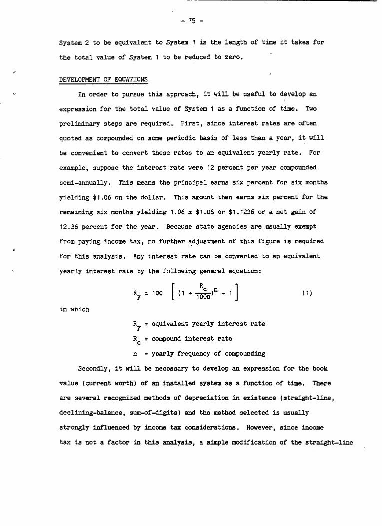
- 75 -
System 2 t o be equivalent t o System 1 is the length of time it takes f o r
t he t o t a l value of System 1 t o be reduced t o zero.
DEVELOPMENT OF EQUATIONS
In order t o pursue t h i s approach, it w i l l be useful to develop an
expression f o r the t o t a l value of System 1 as a function of time. Two
preliminary steps are required. F i r s t , s ince i n t e r e s t rates are often
quoted as compounded on some periodic b a s i s of less than a year, it w i l l
be convenient to convert these rates t o an equivalent yearly rate.
example, suppose the interest rate were 12 percent p e r year compounded
semi-annually.
yielding $1.06 on the dol la r .
remaining six months yielding 1.06 x $1.06 o r $1.1236 o r a ne t gain of
12.36 percent f o r the year. Because state agencies are usually exempt
from paying income tax, no fur ther adjustment of t h i s figure is required
f o r t h i s analysis.
yearly i n t e r e s t rate by the following general equation:
For
This means the pr incipal earns six percent f o r six months
This amount then earns six percent f o r the
Any i n t e r e s t rate can be converted t o an equivalent
= 100 ( 1 + - Rc 1" - 1 1 RY [ loon in which
R
Rc = compound i n t e r e s t rate
n = yearly frequency of compounding
= equivalent yearly i n t e r e s t rate Y
Secondly, i t w i l l be necessary t o develop an expression f o r the book
value (current worth) of an ins ta l led system as a function of time. There
are several recognized methods of depreciation in existence (straight-line,
declining-balance, sum-of-digits) and the method selected is usually
s t rongly influenced by income tax considerations.
tax is not a f ac to r in this analysis , a simple modification of the s t ra ight - l ine
However, s ince income

method w i l l be used.
system w i l l be the f rac t ion of remaining l i f e multiplied by the current
It will be assumed that the book value of an e x i s t i n g
( i n f l a t e d ] cos t of installing an ident ica l new systeII1. This leads t o the
following general expression:
in which
B = book value
L = expected l i fe of system
t = time (years) that system has been i n place
C = i n i t i a l cost of system
r = i n f l a t ion rate (percent per year)
It is now possible t o write an expression giving the total value of
System 1 as a function of time: L v1 = (C2 - C1)[1 + m] R t + [+7c1 [l + +j]t
i n which 0 5 t 5 L1 and
v1 = value of System 1 a t time t
C1 = ini t ia l cos t of System 1
C2 = in i t ia l cos t of System 2
R = yearly interest rate
r = yearly in f l a t ion rate
t = time (years) that System 1 has been in place
L1 = expected l i f e (years) of System 1
( 3 )
The first term on the right represents the growth of the o r ig ina l
pr inc ipa l (C2 - C,) while the second term represents the decl ining book
value of the in s t a l l ed system.
d i r e c t l y applicable only up t o time t = L1.
must be reduced by the cost of the next generation of System 1 and t is
It should be noted that th i s equation is
A t t h i s point, the pr inc ipa l
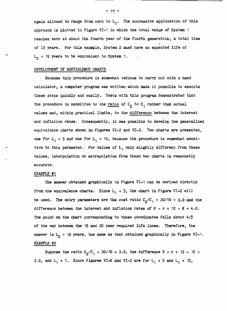
- 77 - again allowed t o range from zero t o L1.
approach is plot ted i n F igure VI-1 in which the t o t a l value of System 1
The successive appl icat ion of t h i s
reaches zero a t about the fourth year of
of 19 years. For t h i s example, System 2
L2 = 19 years to be equivalent t o System
DEVELOPMENT OF EQUIVALENCE CHARTS
the fourth generation, a t o t a l time
must have an expected l i f e of >
1.
Because this procedure is somewhat tedious to carry out with a hand
calculator , a computer program was writ ten'which made it possible t o execute
these s teps quickly and easi ly .
the procedure is sens i t ive to the r a t i o of C2 t o C
values and, wi th in practical limits, t o the difference between the interest
and in f l a t ion rates.
equivalence charts shown in Figures VI-2 and VI-3.
one f o r L1 = 5 and one f o r L1 = 10, because the procedure is somewhat sensi-
Tests with t h i s program demonstrated tha t
rather than actual 1 - Consequently, i t was possible t o develop the generalized
Two charts are presented,
t i v e t o this parameter,
values, interpolat ion o r extrapolation from these two charts i s reasonably
accurate.
EXAMPLE I1
For values of Ll only s l i g h t l y d i f f e ren t f r o m these
The answer obtained graphically i n Figure VI -1 can be derived d i r e c t l y
from the equivalence charts.
be used.
difference between the i n t e r e s t and i n f l a t i o n rates of R - r = 12 - 8 = 4.0.
The point on the chart corresponding t o these coordinates f a l l s about 4 / 5
of the way between the 15 and 20 year required l i fe l i nes . Therefore, the
Since L1 = 5, the chart in Figure VI-2 w i l l
The entry parameters are the cos t r a t i o C2/C, = 30/10 = 3.0 and t he
answer is L2 = 19 years, the same as
EXAMPLE a2
Suppose the r a t i o C2/CI = 30/10
3.0, and L1 = 7. Since Figures VI-2
that obtained graphically in Figure VI-1.
= 3.0, the difference R - r z 13 - 10 =
and VI-3 are f o r L, = 5 and L1 = 10,

- 78 -
LI = 5
CI = 10
c z = 20
R = 12
r r 0
Value of System I ( V , )
Ncqotivc qrowth represents lots
of interest.
FIGURE V I - 1. - Illustration of method for determining the required life of System 2.
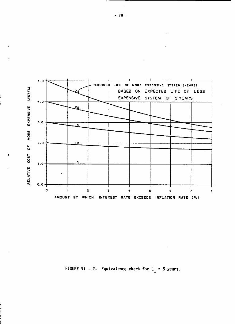
- 79 -
t '
I W c v) >. cn
W
cn 2 W 0, X W
W a 0 I
z
L L 0
c v) s W
c A W
L a
a
5 . 0
4.0
3 .0
2 . 0
I .o
0.0
R E O U I R E D LIFE O F MORE EXPENSIVE SYSTEM ( Y E A R S )
BASED ON EXPECTED LIFE OF LESS
0 I 2 3 4 5 6 f 8
AMOUNT BY WHICH INTEREST RATE EXCEEDS INFLATION RATE (2)
FIGURE V I - 2. Equivalence chart for L1 = 5 years.
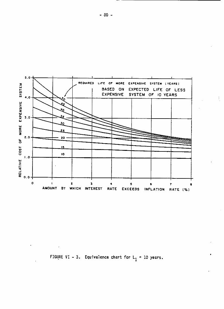
- 80 -
REOUIREO LIFE OF MORE EXPENSIVE SYSTEM ( Y E A R S 1
BASED ON EXPECTED LIFE OF LESS EXPENSIVE SYSTEM OF 10 YEARS
2 3 4 5 6 7 8 0 I
AMOUNT BY WHICH INTEREST RATE EXCEEDS INFLATION RATE ( % )
FIGURE V I - 3. Equivalence chart for L1 = 10 years.
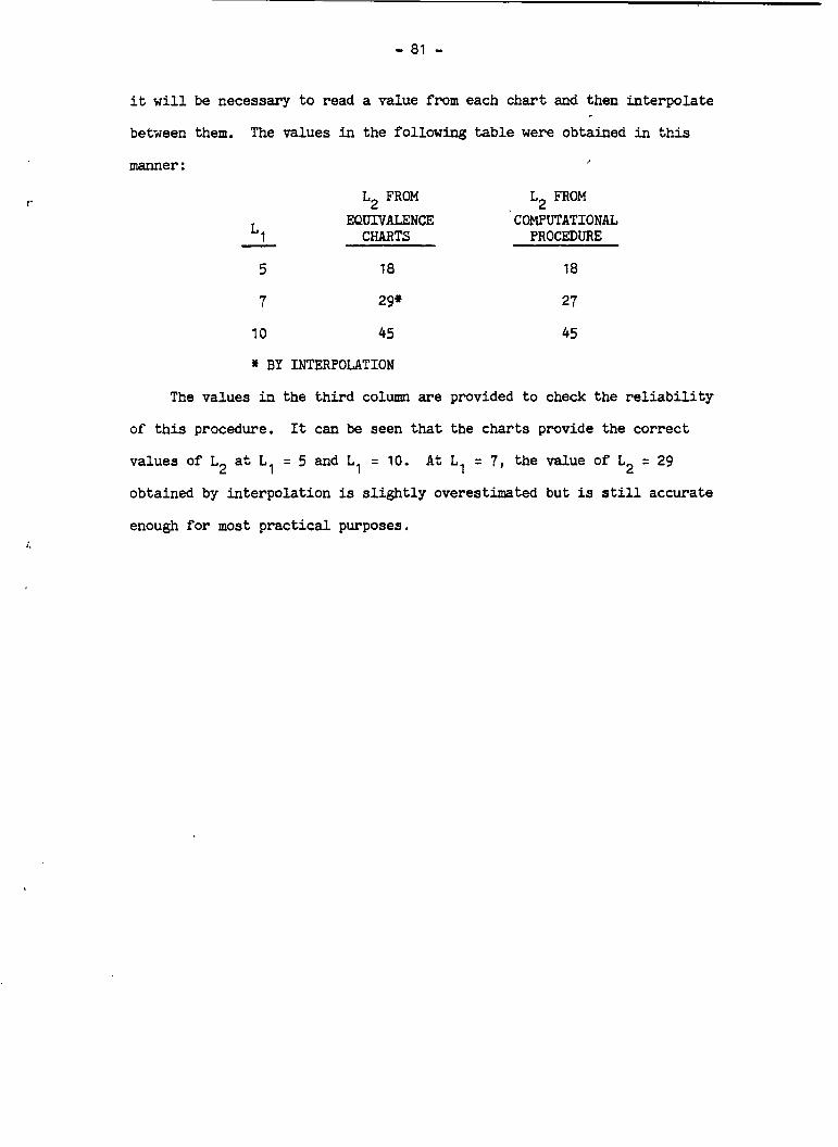
- 81 - it w i l l be necessary t o read a value from each chart and then in te rpola te
between them. The values in the following t a b l e were obtained in t h i s
manner :
L2 FROM L2 FROM EQUNALENCE CWUTATIONAL
Ll CHARTS PROCEDURE - 5 18 18
7 29' 27
10 45 45
* BY INTERPOLATION
The values i n the t h i r d column are provided t o check the r e l i a b i l i t y
of t h i s procedure. It can be seen that t h e charts provide the cor rec t
values of L2 a t L
obtained by interpolat ion is s l i g h t l y overestimated but is still accurate
= 5 and L1 = 10. A t L1 = 7 , the value of L2 = 29 1
enough f o r most p rac t i ca l purposes.