Evaluation of Serverless Computing Frameworks Based on ...
76
Aalto University School of Science Degree Programme of Computer Science and Engineering Sunil Kumar Mohanty Evaluation of Serverless Computing Frame- works Based on Kubernetes Master’s Thesis Espoo, July 6, 2018 Supervisor: Professor Mario Di Francesco, Aalto University Instructor: Gopika Premsankar M.Sc. (Tech.)
Transcript of Evaluation of Serverless Computing Frameworks Based on ...

Aalto University
School of Science
Degree Programme of Computer Science and Engineering
Sunil Kumar Mohanty
Evaluation of Serverless Computing Frame-works Based on Kubernetes
Master’s ThesisEspoo, July 6, 2018
Supervisor: Professor Mario Di Francesco, Aalto UniversityInstructor: Gopika Premsankar M.Sc. (Tech.)

Aalto UniversitySchool of ScienceDegree Programme of Computer Science and Engineering
ABSTRACT OFMASTER’S THESIS
Author: Sunil Kumar Mohanty
Title:Evaluation of Serverless Computing Frameworks Based on Kubernetes
Date: July 6, 2018 Pages: 76
Professorship: Mobile Computing, Services and Secu-rity
Code: SCI3045
Supervisor: Professor Mario Di Francesco
Instructor: Gopika Premsankar M.Sc. (Tech.)
Recent advancements in virtualization and software architectures have led to thebirth of the new paradigm of serverless computing. Serverless computing, alsoknown as function-as-a-service, allows developers to deploy functions as comput-ing units without worrying about the underlying infrastructure. Moreover, noresources are allocated or billed until a function is invoked. Thus, the major ben-efits of serverless computing are reduced developer concern about infrastructure,reduced time to market and lower cost. Currently, serverless computing is gener-ally available through various public cloud service providers. However, there arecertain bottlenecks on public cloud platforms, such as vendor lock-in, computa-tion restrictions and regulatory restrictions. Thus, there is a growing interest toimplement serverless computing on a private infrastructure. One of the preferredways of implementing serverless computing is through the use of containers. Acontainer-based solution allows to utilize features of existing orchestration frame-works, such as Kubernetes. This thesis discusses the implementation of serverlesscomputing on Kubernetes. To this end, we carry out a feature evaluation of fouropen source serverless computing frameworks, namely Kubeless, OpenFaaS, Fis-sion and OpenWhisk. Based on predefined criteria, we select Kubeless, Fissionand OpenFaaS for further evaluation. First, we describe the developer experienceon each framework. Next, we compare three different modes in which OpenFaaSfunctions are executed: HTTP, serializing and streaming. We evaluate the re-sponse time of function invocation and ease of monitoring and management oflogs. We find that HTTP mode is the preferred mode for OpenFaaS. Finally, weevaluate the performance of the considered frameworks under different workloads.We find that Kubeless has the best performance among the three frameworks,both in terms of response time and the ratio of successful responses.
Keywords: docker, container, kubernetes, serverless, microservices
Language: English
2

Acknowledgments
I would like to thank my thesis supervisor Professor Mario Di Francescofor giving me an opportunity to work on this thesis and providing valuableinsights. I would like to specifically thank my instructor Gopika Premsankarwho has always kept her door open to answer my unending queries. I amgrateful to her for constantly guiding me through out this thesis work.
I would like to thank my parents, sisters, in-laws and friends for theirconstant support and motivation. Special thanks to my wife for constantlyencouraging me throughout my years of studies and through the process ofwriting this thesis. This thesis would not have been possible without theirhelp and support.
Thank you.
Espoo, July 6, 2018
Sunil Kumar Mohanty
3

Abbreviations and Acronyms
3GPP 3rd Generation Partnership ProjectAPI Application programming interfaceAWS Amazon Web ServicesCD Continuous DeliveryCDN Content Delivery NetworkCI Continuous IntegrationCLI Command-line InterfaceCNCF Cloud Native Computing FoundationFaaS Function as a ServiceGKE Google Kubernetes EngineHPA Horizontal Pod AutoscalerIaaS Infrastructure as a ServiceIoT Internet of ThingsIPC Interprocess CommunicationPaaS Platform as a ServiceQPS Queries per secondREST Representational State TransferRBAC Role Based Access ControlSaaS Software as a ServiceUTS Unix Time SharingVM Virtual MachineVMM Virtual Machine Monitor
4

Contents
Abbreviations and Acronyms 4
1 Introduction 81.1 Motivation . . . . . . . . . . . . . . . . . . . . . . . . . . . . . 91.2 Contribution . . . . . . . . . . . . . . . . . . . . . . . . . . . . 101.3 Structure of thesis . . . . . . . . . . . . . . . . . . . . . . . . 11
2 Background 122.1 Virtualization . . . . . . . . . . . . . . . . . . . . . . . . . . . 12
2.1.1 Hypervisor-based virtualization . . . . . . . . . . . . . 132.1.2 Container-based virtualization . . . . . . . . . . . . . . 14
2.2 Docker . . . . . . . . . . . . . . . . . . . . . . . . . . . . . . . 172.3 Container orchestration . . . . . . . . . . . . . . . . . . . . . . 21
2.3.1 Docker Swarm . . . . . . . . . . . . . . . . . . . . . . . 212.3.2 Kubernetes . . . . . . . . . . . . . . . . . . . . . . . . 23
2.4 Microservices . . . . . . . . . . . . . . . . . . . . . . . . . . . 272.5 Serverless computing . . . . . . . . . . . . . . . . . . . . . . . 29
2.5.1 Definition . . . . . . . . . . . . . . . . . . . . . . . . . 302.5.2 Existing platforms . . . . . . . . . . . . . . . . . . . . 312.5.3 Use cases . . . . . . . . . . . . . . . . . . . . . . . . . 322.5.4 Benefits and Challenges . . . . . . . . . . . . . . . . . 33
3 Open source serverless frameworks 353.1 Evaluation criteria . . . . . . . . . . . . . . . . . . . . . . . . 353.2 Frameworks . . . . . . . . . . . . . . . . . . . . . . . . . . . . 36
3.2.1 Kubeless . . . . . . . . . . . . . . . . . . . . . . . . . . 363.2.2 Apache OpenWhisk . . . . . . . . . . . . . . . . . . . . 383.2.3 Fission . . . . . . . . . . . . . . . . . . . . . . . . . . . 403.2.4 OpenFaaS . . . . . . . . . . . . . . . . . . . . . . . . . 41
3.3 Summary and comparison . . . . . . . . . . . . . . . . . . . . 43
5

4 Evaluation 464.1 Methodology . . . . . . . . . . . . . . . . . . . . . . . . . . . 464.2 Ease of development . . . . . . . . . . . . . . . . . . . . . . . 474.3 Comparison of Watchdog modes in OpenFaaS . . . . . . . . . 49
4.3.1 Setup . . . . . . . . . . . . . . . . . . . . . . . . . . . 494.3.2 Results . . . . . . . . . . . . . . . . . . . . . . . . . . . 53
4.4 Performance of the different frameworks . . . . . . . . . . . . 554.4.1 Setup . . . . . . . . . . . . . . . . . . . . . . . . . . . 564.4.2 Results . . . . . . . . . . . . . . . . . . . . . . . . . . . 57
5 Conclusion 60
A Fission 70A.1 Function code . . . . . . . . . . . . . . . . . . . . . . . . . . . 70A.2 Examples of Commands . . . . . . . . . . . . . . . . . . . . . 70
B Kubeless 71B.1 Function code . . . . . . . . . . . . . . . . . . . . . . . . . . . 71B.2 Examples of Commands . . . . . . . . . . . . . . . . . . . . . 71
C OpenFaaS 72C.1 Create a new function . . . . . . . . . . . . . . . . . . . . . . 72
C.1.1 Auto generated function code . . . . . . . . . . . . . . 72C.1.2 Sample yml file for OpenFaaS functions . . . . . . . . . 73
C.2 Deploy function . . . . . . . . . . . . . . . . . . . . . . . . . . 73
D Function Code 75D.1 Serializing Function - Classic . . . . . . . . . . . . . . . . . . . 75D.2 HTTP Function . . . . . . . . . . . . . . . . . . . . . . . . . . 75D.3 Streaming Function . . . . . . . . . . . . . . . . . . . . . . . . 76
6

List of Figures
2.1 Hypervisor-based virtualization [60]. . . . . . . . . . . . . . . 132.2 Container-based virtualization. . . . . . . . . . . . . . . . . . 142.3 cgroup hierarchical structure. . . . . . . . . . . . . . . . . . . 162.4 Docker architecture [60]. . . . . . . . . . . . . . . . . . . . . . 182.5 Multiple Docker containers using the same image. . . . . . . . 202.6 Docker Swarm architecture. . . . . . . . . . . . . . . . . . . . 212.7 Kubernetes architecture. . . . . . . . . . . . . . . . . . . . . . 242.8 Monoliths and microservices [54]. . . . . . . . . . . . . . . . . 272.9 Google Trends of “serverless” in last five years. . . . . . . . . . 302.10 Developer control in different computing paradigms [40]. . . . 30
3.1 High-level architecture of Kubeless. . . . . . . . . . . . . . . . 373.2 OpenWhisk: high level architecture [3]. . . . . . . . . . . . . . 383.3 OpenWhisk system architecture [3]. . . . . . . . . . . . . . . . 393.4 Fission system architecture [14]. . . . . . . . . . . . . . . . . . 403.5 OpenFaaS system architecture [29]. . . . . . . . . . . . . . . . 423.6 OpenFaaS: interaction between components [17]. . . . . . . . . 43
4.1 System architecture of OpenFaaS on a Kubernetes cluster. . . 504.2 OpenFaaS watchdog modes [34]. . . . . . . . . . . . . . . . . . 524.3 Average response time (in ms) for different OpenFaaS watch-
dog modes. . . . . . . . . . . . . . . . . . . . . . . . . . . . . 544.4 Density of response time for different watchdog modes in Open-
FaaS. . . . . . . . . . . . . . . . . . . . . . . . . . . . . . . . . 554.5 Average response time (in milliseconds) for different serverless
frameworks with 1, 5, 25 and 50 function replicas. . . . . . . . 58
7

Chapter 1
Introduction
Recent advancements in technology have been pushing software developersto generate value quickly and release new features faster than before. Thetime to market is also becoming a critical metric, driven primarily by thefear of competition [48]. In the past, developers spent a significant amountof time in planning and maintaining infrastructure in addition to writingcode for business logic. Developers purchased bare metal servers and eitherinstalled them on-premise or leased rack space in data centers. Moreover,they had to over-provision their infrastructure to account for scalability andresilience [37]. Thus, much of the infrastructure remained unutilized fora significant portion of time. The advent of virtualization improved theutilization of the underlying hardware, resulting in significant reduction incost [39, 62]. This development led to the rise of cloud computing and devel-opers started treating hardware as a utility. Presently, developers no longerneed to own the actual hardware and pay only for what they use. Of the sev-eral virtualization technologies available, hypervisor-based virtualization andcontainer-based virtualization are the most popular ones [53, 64]. Container-based virtualization has become more popular in the recent years as it allowsfor better utilization of resources, faster provisioning and de-provisioning,and rapid scalability when compared to hypervisor-based virtualization [61].While hypervisor-based virtualization provides computing resources on de-mand, container-based virtualization provides applications on demand. Ad-vancements in container technology have made developers switch from a largemonolithic architecture to an architecture based on distributed microser-vices [51].
Such a shift to containers and microservices architecture has given birthto a new paradigm known as serverless computing [45]. In serverless comput-ing (also known as function-as-a-service), functions are written and deployedto a platform without developers worrying about the underlying infrastruc-
8

CHAPTER 1. INTRODUCTION 9
ture. The latter is generally managed by a third-party service provider ora different team (when using a private cloud). It is important to note thatserverless computing does not mean the absence of servers. The term ‘server-less’ is a misnomer and a marketing jargon made popular by the Amazon WebServices (AWS) Lambda1 service. The implementation still happens on realservers, but developers are relieved of installing and managing the infras-tructure. The development team can then focus on the business logic anddeploy the functions as soon as they are ready. These functions are com-pletely stateless, allowing them to scale rapidly and independent from eachother. As a consequence, serverless computing has made developers changethe way they design, develop and deploy modern software [37].
1.1 Motivation
The main motivation behind the rapid adoption of serverless computing are:decreased concern for developers, reduced time to market, billing for codeexecution instead of resource usage, and reduced effort in application man-agement and operations. Although utilizing serverless offerings of publiccloud service providers is very easy and convenient, there are several scenar-ios where developers prefer their private infrastructure. Some of the majorreasons are as follows. Certain organizations would like to use their owninfrastructure for regulatory reasons or also to utilize existing private infras-tructure. A serverless environment allows them to bill individual businessunits based on execution time, thus creating a simple and cheaper cost modelwithin the organization. Moreover, each public cloud provider has its own im-plementation of serverless computing, forcing developers to write their codein a certain way. Hence, one of the major risks in adopting a public serverlessplatform is vendor lock-in. Each public cloud provider also has limitationsin terms of languages supported, maximum execution duration, maximumconcurrent executions and so on. All these bottlenecks can be addressed ifserverless computing is realized in a private cloud environment, thus givingan organization complete control over the infrastructure.
Edge computing, specifically data analytics at the edge, is particularlysuited for serverless computing [67]. Presently, Internet of Things (IoT) sen-sors produce a large volume of data that has to be analyzed to extract usefulinformation. A private serverless infrastructure can be created on the IoTgateways to process the data with very low latencies (as they are located closeto the devices generating the data). This is all the more beneficial when the
1https://aws.amazon.com/lambda/

CHAPTER 1. INTRODUCTION 10
IoT gateways do not have an Internet connection to connect to cloud services.With a serverless environment, consumers can deploy their functions and bebilled for only the execution time at the edge. Here, function-as-a-servicecan be combined with gateway as a service [65]. Such a model will simplifythe programming of IoT devices and improve the utilization of resources atthe gateways.
The reasons described above have motivated us to implement serverlesscomputing on a private infrastructure. Indeed, serverless computing can beimplemented in a private cloud through containers [63]. There are many opensource tools available today which have made orchestration (i.e., the deploy-ment and scaling) of containers easy. One of the most popular open sourcecontainer orchestration tools is Kubernetes2, which is developed by Google.The goal of this thesis is to implement and evaluate serverless computingin a private cloud by using Kubernetes as a container orchestration tool.Specifically, we aim to evaluate existing open source serverless computingframeworks in terms of their features and performance.
1.2 Contribution
The contributions of this work are the following.
• Establishing the feasibility of setting up a serverless platform on aprivate cloud using Kubernetes as a container orchestration tool
• Evaluating the features of existing open source serverless frameworks,namely, OpenFaaS, Kubeless, Fission and OpenWhisk
• Implementing a serverless environment on virtual servers by using Open-FaaS, Kubeless and Fission
• Evaluating the serverless platforms in terms of ease of development andmonitoring of the functions; in particular, the steps needed to build anddeploy functions on each considered framework
• Evaluating the performance (in terms of response time and ratio of suc-cessful responses) of the considered frameworks under different work-loads
2https://kubernetes.io/

CHAPTER 1. INTRODUCTION 11
1.3 Structure of thesis
The rest of this thesis is structured as follows. Chapter 2 introduces the rele-vant background about virtualization, containers, Kubernetes, microservicesand serverless computing. Chapter 3 discusses several open source solutionsto implement serverless computing. Chapter 4 describes the implementationof serverless computing on a Kubernetes cluster by using OpenFaaS, Kubelessand Fission. It also evaluates the performance of the serverless environmentwith each of these frameworks. Finally, Chapter 5 provides some concludingremarks and directions for future work.

Chapter 2
Background
The chapter provides background information on the technologies and con-cepts relevant to this thesis. Section 2.1 introduces the concept of virtualiza-tion and describes hypervisor and container-based virtualization. Section 2.2describes the features of Docker, a popular software tool for Linux contain-ers. Section 2.3 discusses two popular container orchestration frameworks,Kubernetes and Docker Swarm. Section 2.4 presents the mircroservices ar-chitecture, one of the driving forces behind serverless computing. Finally,Section 2.5 describes the concept of serverless computing, its benefits anddisadvantages and highlights certain use cases for serverless computing.
2.1 Virtualization
Virtualization lies at the heart of serverless computing. Hence, it is im-portant to clearly introduce virtualization to better understand serverlesscomputing. Although virtualization has gained rapid popularity in the lastfew years, its origin can be traced to 1960’s when IBM introduced the ideawith the M44/44X system [49]. Virtualization enables developers to run mul-tiple virtualized instances on top of a server. The instances run in completeisolation and also provide rapid scalability, better utilization of computingresources and reduction in cost [39, 62]. The two most popular virtualizationtechnologies are hypervisor-based virtualization and container-based virtu-alization (also known as operating system-level virtualization). We describethese technologies next.
12

CHAPTER 2. BACKGROUND 13
Figure 2.1: Hypervisor-based virtualization [60].
2.1.1 Hypervisor-based virtualization
In the words of Popek and Goldberg [69], a virtual machine (VM) can bedefined as “an efficient, isolated duplicate of the real machine”. Over thelast decade, hypervisor-based virtualization has been a popular method forimplementing VMs. This approach relies on a software called a hypervisor orvirtual machine monitor (VMM) that lies between the hardware and VMs. Itcan host multiple VMs on top of it. The VMM has the following three char-acteristics [69]: provides environments for programs which are identical tothe original machine had the program been run directly there; ensures min-imal performance degradation for programs running in these environments;the VMM has complete control over the resources on the host system.
Hypervisor-based virtualization can be further divided into two types(Figure 2.1): Type 1, which is native or bare metal and Type 2, whichis hosted [57, 73]. A Type 1 hypervisor architecture runs the hypervisordirectly on top of the underlying host’s hardware. The VMs run on top ofthe hypervisor. Here all the necessary scheduling and resource allocationare done by the hypervisor. Some of the notable hypervisors based on thisarchitecture are Xen [42], Oracle VM, VMware ESX [66], Microsoft Hyper-V [78]. In a Type 2 hypervisor architecture, the hypervisor runs on top ofthe host operating system (OS). The VMs run on top of the hypervisor. Here,the hypervisor relies on the host OS for processor scheduling and resourceallocation. Some of the notable hypervisors based on this architecture areOracle VirtualBox, VMWare Workstation [77], Microsoft Virtual PC [58],QEMU [43], and Parallels1.
The major benefit of hypervisor-based virtualization is that it allows usersto run multiple VMs in isolation on a single machine. This allows developers
1http://www.parallels.com

CHAPTER 2. BACKGROUND 14
Figure 2.2: Container-based virtualization.
to create multiple environments with different hardwares and OS on a singlehardware. For example, a VM can be easily configured with 1 GB of memoryand 1 CPU on a host machine having 32 GB memory and 4 CPUs. The sameVM can then be reconfigured to have 4 GB of memory and 2 CPUs withoutmaking any actual hardware changes, but only some configuration changes.Developers can save a VM as an image and port this image to differenthardware or data centers. This gives developers a seamless experience fromdevelopment to testing to production. Furthermore, cloud service providershave created interfaces which allow the creation of the VMs through APIs.This has allowed developers to scale applications based on demand whichresulted in the initial wave of cloud computing.
Despite the many benefits, hypervisor-based virtualization has its limita-tions. Firstly, there is some performance deterioration in VMs as comparedto native machines [42]. Moreover, VMs can be slow as they still need to bebooted up like a normal OS, resulting in long start up time.
2.1.2 Container-based virtualization
Containers, also known as operating system (OS)-level virtualization, are alightweight alternative to hypervisor-based virtualization. Containers createmultiple, isolated userspace instances on top of the same OS kernel [80]. Thuscontainers provide an abstraction on top of the OS kernel allowing multipleguest processes to run within a container in isolation from other containers.As shown in Figure 2.2, each container behaves as an independent OS withoutthe need for an intermediate layer such as a hypervisor.

CHAPTER 2. BACKGROUND 15
There are multiple solutions for OS-level virtualization. Linux-VServer2
is one of the oldest implementations. It uses the chroot() barrier to pre-vent unauthorized modification of the file system [76, 80]. OpenVZ3 relies onkernel namespaces, allocating a PID namespace to each of the containers toisolate them [76, 80]. OpenVZ relies on a modified Linux kernel and severaluser-level tools [46]. Virtuozzo4 is another implementation of Linux containertechnology and is based on OpenVZ. LXC5 is an implementation of container-ization which uses Linux kernel functionalities already implemented in theupstream Linux kernel [72]. Moreover, the use of Linux Security Modules byLXC makes it stand out [72]. In this thesis, we use the LXC implementationof containers to achieve our goal of creating a serverless environment. Next,we describe the key enabling Linux kernel functionalities of LXC.
Control groups
Control groups6, also called as cgroups, enable LXC to control resources.These resources include memory, CPU, block I/O, devices and traffic con-troller [72]. It provides a mechanism for aggregating sets of processes intohierarchical groups and controls the allocation of resources per cgroup [80].Each groups inherits from its parent. As shown in Figure 2.3, each processbelongs to a node in the hierarchy which is arranged as a tree and each nodecan have multiple processes sharing the same set of resources. Cgroups as-sociate these sets of processes to one or more subsystems. Subsystems arecontrollers which control access to the underlying resource. For example, thememory controller keeps track of pages used by each group. Each cgroupalso has a virtual file system associated with it. Cgroups are configurableallowing for dynamic allocation of resources. Thus, cgroups are responsiblefor accounting and limiting how many resources a set of processes in a cgroupcan access.
Namespaces
Namespaces7 allow different processes to have their own view of the systemresources and are used by containers to provide resource isolation. Changesmade to the resource in a namespace are only visible within the same names-
2http://linux-vserver.org3http://www.openvz.org4http://www.virtuozzo.com5https://linuxcontainers.org6https://www.kernel.org/doc/Documentation/cgroup-v1/cgroups.txt7http://man7.org/linux/man-pages/man7/namespaces.7.html

CHAPTER 2. BACKGROUND 16
Figure 2.3: cgroup hierarchical structure.
pace. This makes the process have their own isolated instance of globalresources. The Linux kernel has seven different namespaces:
• Cgroup namespaces are responsible for virtualizing the view of process’scgroup. Each cgroup namespace has its own cgroup root directories.
• Interprocess Communication (IPC) namespaces isolate IPC resources,such as System V IPC objects and Posix message queues. Each IPCnamespace has its own set of IPC resources and their visibility is limitedto the namespace to which they belong.
• Network namespaces isolate the networking resources, such as network-ing devices, IPv4 and IPv6 protocol stacks, routing tables, firewalls,and so on. A physical device is visible in only one network namespace.Networking between namespaces can be done by creating tunnels usinga virtual Ethernet interface.
• Mount namespaces8 isolate the list of mount points in each namespaceinstance, thereby restricting the processes in each mount namespaceinstance to see distinct directory hierarchies.
• PID namespaces9 isolate the processID, resulting in processes in differ-ent PID namespaces having the same PID number. This functionality
8http://man7.org/linux/man-pages/man7/mount namespaces.7.html9http://man7.org/linux/man-pages/man7/pid namespaces.7.html

CHAPTER 2. BACKGROUND 17
allows a container to suspend or resume a set of processes within itand then migrate the container to a new host, retaining the same PIDnumber.
• User namespaces10 isolate security-related identifiers and attributes,such as user ids, group ids, root directory, keys and capabilities. Forexample, a process can have full privileges inside a user namespace, butat the same time be unprivileged outside the user namespace.
• Unix Time Sharing (UTS) namespaces isolate two system identifiers:the hostname and the domain name. This allows a single system toappear to have a different host name and domain name to differentprocesses.
Containers have been challenging hypervisor-based virtualization for adop-tion by cloud computing providers [64]. There are many reasons for this.Unlike VMs, containers share the same Linux kernel. Hence, container im-ages are not full-fledged operating systems like VMs. This makes containersvery light-weight, scalable and easy to port. Containers are faster to bootwhen compared to VMs [52]. In fact, the performance of containers is nearnative in comparison to hypervisor-based virtualization [64]. Since contain-ers have the ability to return unused resources to the host machine or othercontainers, resource utilization is better than hypervisor-based virtualizationwherein resources are locked for each VM [80]. However, since containerson the same host share the same Linux kernel, they provide less isolation ascompared to VMs.
2.2 Docker
Docker11 is an open source platform for building, shipping and deployingcontainers. It uses the resource isolation features provided by the Linuxkernel, such as cgroups and namespaces [38]. Docker-based applications canbe deployed faster than traditional non-containerized applications. Moreover,Docker allows developers to configure many infrastructure components, suchas memory, CPU and networking, through a Dockerfile (described later) orthe command line. This allows developers to manage infrastructure similarto how they manage applications. Ultimately, it helps developers in reducingthe time to market [31]. Docker provides a platform to run almost any
10http://man7.org/linux/man-pages/man7/user namespaces.7.html11https://docs.docker.com/
CHAPTER 2. BACKGROUND 18
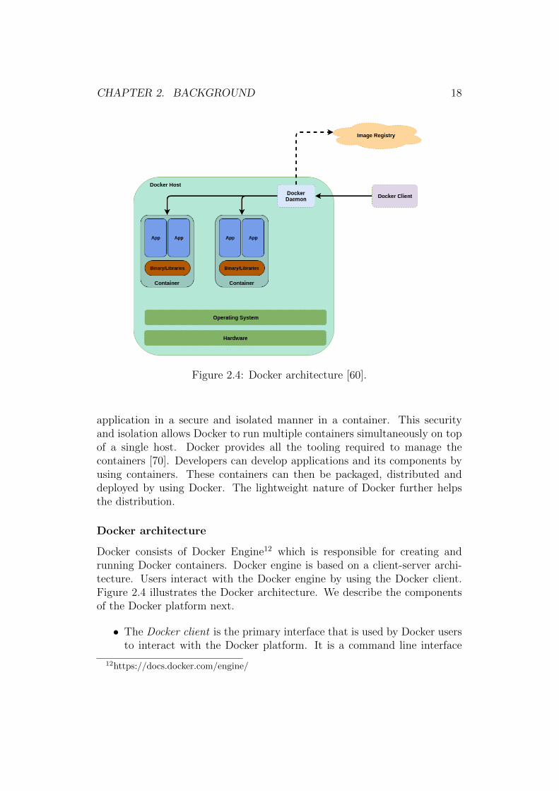
Figure 2.4: Docker architecture [60].
application in a secure and isolated manner in a container. This securityand isolation allows Docker to run multiple containers simultaneously on topof a single host. Docker provides all the tooling required to manage thecontainers [70]. Developers can develop applications and its components byusing containers. These containers can then be packaged, distributed anddeployed by using Docker. The lightweight nature of Docker further helpsthe distribution.
Docker architecture
Docker consists of Docker Engine12 which is responsible for creating andrunning Docker containers. Docker engine is based on a client-server archi-tecture. Users interact with the Docker engine by using the Docker client.Figure 2.4 illustrates the Docker architecture. We describe the componentsof the Docker platform next.
• The Docker client is the primary interface that is used by Docker usersto interact with the Docker platform. It is a command line interface
12https://docs.docker.com/engine/

CHAPTER 2. BACKGROUND 19
by which the users send commands. The client then sends these com-mands to the Docker daemon which executes them. The client usesa Representational State Transfer (REST) Application ProgrammingInterface (API) to interact with the Docker daemon. The client anddaemon need not be on the same host.
• The Docker daemon is responsible for managing Docker containers onthe host system. It runs on the host machine and waits for Docker APIrequests from the Docker client. Users cannot interact with the Dockerdaemon directly.
• Docker images are read-only templates with the source code for cre-ating and running containers. These are the primary building blocksof Docker containers. Every Docker image contains libraries and bi-naries that are necessary to build applications. Developers can buildtheir own image or download images built by other developers. Tocreate their own image, developers write instructions in a Dockerfile(described next). Each step in the Dockerfile creates a layer in theimage and the layers are combined by using a file system called Unionfile system (UnionFS). Whenever a change is made to the image, a newlayer containing only the changes is added on top of the existing layers.This allows for the layers to be used as a cache which can be reused.The layers are read only in nature. Whenever developers make anysmall change to their code, Docker uses the image from the cache andcreate a new layer on top of the image with just the necessary changes.This also makes the process for rebuilding images fast [38].
• Dockerfile13 is a text file that contains all the information needed tobuild a Docker image. User can use the docker build command tobuild an image from a Dockerfile. The Dockerfile is composed of vari-ous instructions which are based on a simple syntax and are executedin sequence. Docker goes through the Dockerfile and executes eachinstruction in the order specified. While executing the instructions,Docker checks if it can reuse an image from the cache instead of cre-ating a new duplicate image. A Dockerfile must start with a ‘FROM’instruction, which specifies the base image from which to build the im-age. The base image can also be SCRATCH, which instructs Dockerto start with an empty filesystem as the base. The subsequent lines inthe Dockerfile adds, deletes and modifies files or configurations.
13https://docs.docker.com/engine/reference/builder

CHAPTER 2. BACKGROUND 20
Figure 2.5: Multiple Docker containers using the same image.
• Docker registries are used to store images. They can be either public orprivate. Developers can build images and store them in these registriesto make the distribution of the images easy. Users can then access anddownload Docker images from these registries by using Docker client.These registries behave similar to source code repositories [59]. One ofthe most popular and largest public Docker registries is Docker Hub14.Developers can also create private repositories and thus control accessto the images.
• Docker containers are the runnable instances of the Docker images.They are created, started, stopped and deleted through the Dockerclient. Multiple instances of containers can be created from the sameDocker image on the same host. Each of these containers run in com-plete isolation of each other. Users can attach persistent storage andnetwork to the containers. As shown in Figure 2.5, when a container iscreated, a new writable layer called the “container layer” is created ontop of the underlying images. Changes made in the running containerare written to this container layer (unless the changes are targetedtowards the persistent storage). When multiple containers are createdfrom the same image, they create their own writable container layer [1].When a container is stopped, the changes made in the writable con-tainer layer are lost.
14https://hub.docker.com

CHAPTER 2. BACKGROUND 21
Figure 2.6: Docker Swarm architecture.
2.3 Container orchestration
As discussed earlier, containers, specifically Docker, make it easy to package,port and deploy applications. These features allow distributed systems toscale up and down easily. Moreover, in a distributed architecture, it is criti-cal that multiple containers can interact among themselves. As the number ofcontainers grow, it becomes very important to automate the whole containermanagement process. This automation is achieved by a container orchestra-tion framework. The primary jobs of a container orchestration frameworkare to provision hosts, start containers, stop containers, provide resilience,link containers, scale containers, update containers, expose containers to theexternal world, and so on. Of the many orchestration frameworks availablein the market, the most popular are Docker Swarm and Kubernetes.
2.3.1 Docker Swarm
Docker Swarm15 is a container orchestration tool which provides native Dockerclustering and scheduling capabilities. The swarm mode is built into DockerEngine v1.12 and later. Swarm commands are also executed through theDocker command line interface and Docker Engine API. Hence, a swarm canbe set up with minimal configuration and with very few commands. Thismakes swarm one of the simpler docker orchestration frameworks available.Some of the key components of Docker swarm are as follows:
• Nodes. A swarm consists of multiple Docker hosts, each of them run-ning in swarm mode. The hosts are referred to as nodes. As shown
15https://docs.docker.com/engine/swarm/key-concepts/
CHAPTER 2. BACKGROUND 22
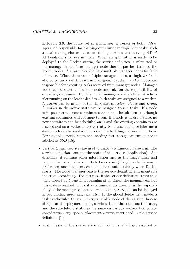
in Figure 2.6, the nodes act as a manager, a worker or both. Man-agers are responsible for carrying out cluster management tasks, suchas maintaining cluster state, scheduling services, and serving HTTPAPI endpoints for swarm mode. When an application is ready to bedeployed to the Docker swarm, the service definition is submitted tothe manager node. The manager node then dispatches tasks to theworker nodes. A swarm can also have multiple manager nodes for faulttolerance. When there are multiple manager nodes, a single leader iselected to carry out the swarm management tasks. Worker nodes areresponsible for executing tasks received from manager nodes. Managernodes can also act as a worker node and take on the responsibility ofexecuting containers. By default, all managers are workers. A sched-uler running on the leader decides which tasks are assigned to a worker.A worker can be in any of the three states, Active, Pause and Drain.A worker in the active state can be assigned to run tasks. If a nodeis in pause state, new containers cannot be scheduled on it althoughexisting containers will continue to run. If a node is in drain state, nonew containers can be scheduled on it and the existing containers arerescheduled on a worker in active state. Node also can have label metadata which can be used as a criteria for scheduling containers on them.For example, special containers needing fast storage can run on nodeslabeled as SSD [18].
• Service. Swarm services are used to deploy containers on a swarm. Theservice definition contains the state of the service (application). Ad-ditionally, it contains other information such as the image name andtag, number of containers, ports to be exposed (if any), node placementpreference, and if the service should start automatically when Dockerstarts. The node manager parses the service definition and maintainsthe state accordingly. For instance, if the service definition states thatthere should be 5 containers running at all times, the manager ensuresthis state is reached. Thus, if a container shuts down, it is the responsi-bility of the manager to start a new container. Services can be deployedin two modes, global and replicated. In the global deployment mode, atask is scheduled to run in every available node of the cluster. In caseof replicated deployment mode, services define the total count of tasks,and the scheduler distributes the same on various workers taking intoconsideration any special placement criteria mentioned in the servicedefinition [19].
• Task. Tasks in the swarm are execution units which get assigned to

CHAPTER 2. BACKGROUND 23
a node and run on the node till completion. Their state is declaredin the service and the swarm realizes the desired state by schedulingtasks [19]. For example, if a service is defined to have three instances ofa specific application, the scheduler creates three tasks. Each of thesetasks is realized through exactly one container. Each task goes throughvarious states16, such as new, pending, assigned, accepted, preparing,starting, running, complete, failed, shutdown, rejected and orphaned.
2.3.2 Kubernetes
Google has long been running containers in its data center [44]. Almost all theapplications at Google are run on containers. These containers were managedthrough an internal container cluster management system called Borg. Oncemany external developers started getting interested in container technologyand Google developed its public cloud infrastructure, it developed a newcontainer management system called Kubernetes17 based on Borg [44, 79].Kubernetes is developed as an open-source product18. Kubernetes can beused to deploy, manage and scale containerized applications [35]. Some ofthe key components of Kubernetes are as follows.
• Pods19 are groups of one or more containers. They are the basic build-ing blocks in Kubernetes. All containers in a pod share the same set ofresources, such as storage, IP address, port space. All the containersare tightly coupled, i.e., they are always co-located and co-scheduled.Kubernetes assigns a unique IP address to a pod. Inside a pod, thecontainers communicate among themselves via localhost. Containers intwo different pods communicate via the pod IP addresses. This makesthe pod behave like a VM. Kubernetes schedules and orchestrates podsand not individual containers. This allows developers to develop inde-pendent components and package them into a pod. Kubernetes sees apods as single working units and scales them accordingly. Pods lackdurability and can be evicted at any point of time. Hence, it is impor-tant for developers to keep their pods stateless.
• Master and nodes. Kubernetes components can be categorized as mas-ter and node components. Nodes are worker machines (such as a VM orphysical machine) which run the pods and are managed by the master
16https://docs.docker.com/engine/swarm/how-swarm-mode-works/swarm-task-states/17http://kubernetes.io/18https://github.com/kubernetes/kubernetes19https://kubernetes.io/docs/concepts/workloads/pods/pod/

CHAPTER 2. BACKGROUND 24
Figure 2.7: Kubernetes architecture.
components. Previously, nodes used to be called minions. Althoughmaster components can be run on any node, they are typically startedon a single machine, referred to as the master. Nodes and masters arecollectively known as a cluster. Master components provide the controlplane layer in Kubernetes. They are responsible for managing contain-ers and respond to various cluster events. Figure 2.7 shows the mastercomponents, such as the API Server, controller manager, scheduler,etcd, cloud controller manager and add-ons [27]. They are described indetail below.
– The API server exposes the Kubernetes API through which allcommunications in the cluster are done. It is also used by develop-ers to connect to Kubernetes cluster and manipulate Kubernetesobject. The APIs are versioned and are designed to scale horizon-tally. Developers can communicate with the API server by usingREST API calls or through command line tools, such as kubectl20
and kubeadm21, which, in turn, use the API server. Moreover,all communication between the master and node components arehandled by the API server [71].
20https://kubernetes.io/docs/reference/kubectl/overview/21https://kubernetes.io/docs/admin/kubeadm/

CHAPTER 2. BACKGROUND 25
– The controller manager runs controllers. Controllers are controlloops that run on the master, check the state of the cluster throughthe API server and move the current state of the Kubernetes ob-ject to the desired state. There are multiple controllers running ina master. Some of the examples of controllers are replication con-troller, endpoint controller, node controller and service accountcontroller. The replication controller is responsible for maintain-ing the desired number of pods. The endpoint controller joins theservices and pods. The node controller keeps track of the avail-ability of nodes. Finally, the service account controller createsdefault accounts and API access tokens [27].
– A scheduler is responsible for placing pods to appropriate nodes.This is done by taking into account various factors, including thecurrent resource utilization and availability on a node and con-straints specified by pods. The scheduler may evict a pod from anode based on the overall state of the cluster [27].
– etcd22 is a distributed, lightweight, consistent and highly availablekey-value data store. It is used to store the configuration and stateinformation of the Kubernetes cluster. It is a open source projectand part of the CoreOS23 project and uses the Raft consensusalgorithm [68] to maintain high availability.
– The cloud controller manager24 is a component introduced in Ku-bernetes v1.6 as an alpha release [26]. It is a cloud specific con-trol loop which runs alongside other master components. Vari-ous cloud providers abstract provider-specific code into the cloudspecific controller manager so as to follow an independent de-velopment lifecycle. The cloud controller manager allows cloudprovides to run cloud-specific code alongside the Kubernetes con-troller. Some of the popular public cloud vendors, such as AmazonWeb Services, Azure, Digital Ocean, Google Compute Engine andOracle have implemented cloud controller managers for their re-spective cloud platforms.
– Add-ons are pods and services that extend the functionality ofKubernetes. An add-on manager is responsible for creating andmanaging the add-ons. An example of an add-on is a Web UIdashboard25 for managing Kubernetes objects.
22https://github.com/coreos/etcd23https://coreos.com/24https://kubernetes.io/docs/concepts/architecture/cloud-controller/25https://kubernetes.io/docs/tasks/access-application-cluster/web-ui-dashboard/

CHAPTER 2. BACKGROUND 26
Node components provide the run time environment for the pods. Fig-ure 2.7 illustrates that node components run on every node. The mainnode components are kubelet and kube-proxy [27].
– Kubelet26 is the most important node component with the respon-sibility to manage pods and containers in the nodes. It respondsto instructions received from the master to create, monitor anddestroy containers running on the node [71]. It also reports thestatus of nodes to the cluster. The kubelet is mainly dependent onPodSpec which is a document in YAML or JSON format that de-scribes the pod. This document is generally served to the kubeletby the API server. It also can be an HTTP endpoint or a file pathwhich the kubelet periodically checks for updates.
– Kube-proxy27 is a network proxy that maps the individual con-tainers to a service and provides load balancing. These proxiesrun on all nodes. They do not understand HTTP and can dosimple TCP and UDP stream forwarding or do round robin loadbalancing across a set of backends.
• Replication Controller28. To handle huge load and for fault tolerance,multiple instances of the same pod need to run at the same time. Eachcopy of the pod is called a replica. These replicas are managed bythe replication controller based on a set of rules defined in a templateknown as pod template. Based on this template, the replication con-troller ensures that a certain number of pods are always running in thecluster. The controller will create or delete replicas as the need maybe [71]. Killing a replication controller does not kill the pods managedby it. Although it is possible to create pods without assigning it to areplication controller, it is advised not to do so (even if only a singlereplica of a pod is to be run). This is because pods may terminateor get destroyed unexpectedly. Attaching them to a replication con-troller ensures that a specified number of pods are always running inthe cluster.
• Services29. While the replication controller ensures that the desirednumber of pods are always running in the cluster, the services makesure that the pods are accessible by the users. As discussed earlier,
26https://kubernetes.io/docs/reference/generated/kubelet/27https://kubernetes.io/docs/reference/generated/kube-proxy/28https://kubernetes.io/docs/concepts/workloads/controllers/replicationcontroller/29https://kubernetes.io/docs/concepts/services-networking/service

CHAPTER 2. BACKGROUND 27
pods have IP addresses assigned to them. However, as the replicationcontroller can create or evict pods, there is no guarantee that a pod willretain its IP address. Changes in IP addresses make it difficult for usersor applications to connect to the pods. Kubernetes solves this issuewith the use of services. A Kubernetes service is an abstraction of a setof pods and defines a policy describing how to access them. The podsare normally discovered by using the label selector30. However, servicescan also be used without label selectors by mapping the service to aspecific endpoint (in the form of an IP address or DNS name). Servicesare REST objects and are assigned IP address. Kubernetes also offersan endpoints object which is updated whenever pods linked in a servicechanges. When a service is created, it also creates a correspondingendpoint object which contains details of the pod based on the labelselector mentioned in the service template.
2.4 Microservices
Figure 2.8: Monoliths and microservices [54].
The microservice architecture has been getting a lot of traction amongsoftware developers. Many leading companies, such as Amazon and Net-flix, have adopted the microservice architecture in their products, which hasfurther fueled the interest of software developers [36]. Figure 2.8 contrasts
30https://kubernetes.io/docs/concepts/overview/working-with-objects/labels/

CHAPTER 2. BACKGROUND 28
the traditional monolithic software architecture to microservices. In mono-lithic applications, the complete application logic is encompassed in a singleunit. The application may consist of several libraries and components butis deployed as a single unit [50]. On the other hand, in the microservicesparadigm, an application is composed of many small, independent services.These services communicate by a lightweight mechanism, often an HTTPAPI [54, 56]. Monolithic applications can be scaled by deploying multiplecopies of the same application. However, the biggest drawback of a mono-lithic application is that it is difficult to understand and modify. This be-comes more apparent as the size and complexity of the application grows.Even a small change in the application requires the complete application tobe rebuilt and redeployed. Since the monolithic application’s code base isgenerally huge, the build time is generally long. Moreover, it follows theprinciple of “one size fits all” for the different modules which could compro-mise resource requirements. For example, certain modules may need morememory whereas the others may need more CPU. However, all modules aredeployed together in one environment. Additionally, the architecture bearsthe burnt of technology lock-in, forcing the developer to use a single languageand framework [51]. On the other hand, in the case of microservices, eachservice can be designed, developed, built, deployed and scaled independently.Each service can have its own programming language and framework. Thus,developers can chose the most suitable environment for each service. Mi-croservices has been identified as a solution to efficiently build and managecomplex software systems [75].
Despite the long list of benefits provided by the microservice architecture,it has many challenges. Since the architecture is distributed in nature, it canbe difficult to identify and isolate errors [59]. The distributed nature alsobrings in dependence on the network for inter-service communication. Theassumption of a reliable, homogeneous and secure network are some of thefallacies of distributed computing [21]. Moreover, the dependence on networkcommunication can have an adverse impact on performance as network callsare slower than in-memory calls [51]. In the microservice architecture, as anapplication becomes bigger, so does the number of services. This increasein the number of services can make an application more fault prone [51].Microservices lead to smaller and independent services resulting in improvedservice level testability. However, integration testing can become complex,especially when the system consists of a large number of services [51, 59].

CHAPTER 2. BACKGROUND 29
2.5 Serverless computing
Traditionally, apart from writing code, software developers had to managethe operational concerns of deploying their application to production. Whenapplications are deployed to a bare metal server, developers have to managethe physical servers, networking, storage, load balancers, operating systems,run times and the application itself. In this scenario, a physical server is theunit of scale and it could take days to order and deploy a new server. Thus,over-provisioning is necessary to meet peak traffic demand. The advent ofvirtualization automated many of these concerns and with a few mouse clicksnew virtual machines could be provisioned. However, developers still need tomanage the network, load balancers, operating systems and runtimes. Fur-thermore, scaling of the VMs takes a few minutes. The subsequent evolutionof virtualization technology, i.e., containers, abstracted away many operat-ing concerns from developers. Container-based applications could be scaledin a matter of seconds. This also spurred the growth of the microservicearchitecture, wherein large applications are decomposed into multiple inde-pendent container-based services. A natural extension of this approach is todecompose applications into multiple independent stateless functions. Thisis known as the serverless computing paradigm. Here, almost all operat-ing concerns are abstracted away, allowing the developers to just write codeand deploy their stateless functions on the serverless platform. The plat-form takes care of executing the functions, storage, server, operating system,container infrastructure, networking, scalability and fault tolerance. Addi-tionally, unlike for bare metal or virtualized instances, the serverless platformtakes care of scaling. Thus, serverless computing is a higher form of managedservices wherein the smallest unit of computing is a function. Hence, server-less computing is also sometime referred to as function-as-a-service (FaaS).Computing resources required to execute a function are provisioned only ondemand and thus, the containers need not be running at all times. The func-tions can be kept active (hot) for a certain duration to improve performancebut they are not perpetually active.
Serverless computing is actually a marketing jargon and it does not meanthe complete absence of servers. It simply implies that developers do nothave to manage the underlying servers and network infrastructure. Whenserverless computing is provided by cloud providers, customers are billed onlyfor the duration of code execution. Serverless computing has been increasingin popularity recently. Figure 2.9 shows the increased interest on “serverless”in the last 2 years as reported by Google Trends.

CHAPTER 2. BACKGROUND 30
Figure 2.9: Google Trends of “serverless” in last five years.
Figure 2.10: Developer control in different computing paradigms [40].
2.5.1 Definition
Serverless computing is still an evolving computing paradigm and does nothave a clear definition which is accepted by the industry or academia. Hence,we review some definitions from the literature. Baldini et al. [40] defineserverless computing based on the level of control a developer has over in-frastructure. As illustrated in Figure 2.10, the authors have placed serverlesscomputing between IaaS (Infrastructure as a Service) and SaaS (Software asa Service). In IaaS, the developer is responsible for provisioning and main-taining both the infrastructure and application. They have to customize howapplications are deployed and scaled. In SaaS, the developers do not have anyknowledge or control over the infrastructure. They also have little flexibilityin terms of the packages and components provided by the SaaS platform.However, in a serverless computing paradigm, the developers have completecontrol over the code that is deployed. The serverless platform takes care ofthe operational aspects of the server, network, load balancing and scaling.Developers have to write stateless code and deploy the functions to the plat-

CHAPTER 2. BACKGROUND 31
form. The platform may run zero to thousands of instances of the functionbased on demand and the developers are billed only for the duration theirfunctions run. Castro et al. [45] describe serverless computing as a cloud-native paradigm which is suitable for short duration stateless functions. Thefunctions are mostly event driven in nature. The platform can respond tobursty workloads by scaling out the functions and scaling in when there isfall in demand. Developers relinquish infrastructure design, quality of ser-vice, scaling and fault tolerance to the platform provider. The Cloud NativeComputing Foundation (CNCF) defines serverless computing as a concept ofbuilding and running applications where server provisioning, maintenance,updates, scaling and capacity planning are abstracted away for developersleaving them to focus on writing code. It also identifies that the serverlessplatforms provide a big advantage to the consumers by not charging themwhen their code is idle [5].
2.5.2 Existing platforms
All the major cloud service providers have a serverless computing platformin their offering. Amazon Web Services (AWS) has AWS Lambda that letsdeveloper run code without provisioning any servers. They also provide AWSGreengrass31 to run AWS lambda functions on edge devices. AWS StepFunctions32 provide a state machine for lambda functions, allowing lambdafunctions to be run in step-by-step manner. Microsoft Azure provides AzureFunctions33, a serverless computing platform which allows developers to runtheir code as functions on Azure infrastructure. IBM also has a serverlesscomputing platform called IBM Cloud Functions34 which is built on top ofApache OpenWhisk35 (described in detail in the next chapter). Google CloudFunctions36 allows developers to run Node.js code as event-driven serverlessfunctions.
All the above serverless offerings require the functions to be written ordeployed in a certain way, resulting in vendor lock-in. Thus, there are severalopen source FaaS frameworks which allow to run serverless computing on pri-vate infrastructure, thereby avoiding any form of vendor lock-in. Some of the
31https://aws.amazon.com/greengrass32https://aws.amazon.com/step-functions/33https://azure.microsoft.com/en-us/services/functions/34https://www.ibm.com/cloud/functions35https://openwhisk.apache.org/36https://cloud.google.com/functions/

CHAPTER 2. BACKGROUND 32
popular ones are Kubeless37, OpenFaaS38, Fission39 and Apache OpenWhisk.We describe these in detail in the next chapter.
2.5.3 Use cases
Serverless computing is ideal for workloads which have sporadic demands.They are ideal for workloads that are short, asynchronous or event-driven andconcurrent work loads [5]. We identify the following use-cases as particularlysuited for serverless computing.
• Database triggers. Event driven computing was one of the main driversbehind serverless computing. Functions as a service can be used torespond to changes in database, such as insert, update and delete op-erations. For instance, serverless functions can be used to write entriesinto an audit table whenever a record gets updated in the database.AWS Lambda is used alongside AWS DynamoDB40 to create databasetriggers [11].
• Serverless computing at edge. Edge computing is described as a keydriver for the serverless computing trend [55, 67]. IoT devices generatea large volume of data which need to be processed in real-time. Server-less functions at the edge can react to events, such as changes in temper-ature and water levels, without having to send all the data to the cloud.Amazon provides AWS Greengrass to run lambda functions at the edgeon local connected devices. These functions can also run when the de-vices are not connected to the Internet. Deploying the functions onthe edge can improve the utilization of resource-constrained devices atthe edge. Furthermore, by abstracting away the infrastructure detailsfrom the developers, code can be deployed on multiple devices. VariousContent Delivery Network providers, such as AWS (Lambda@Edge41)and Cloudflare (Cloudflare Workers42) provide serverless computing attheir edge infrastructure. Developers can use this to perform tasks suchas to modify headers, to carry out A/B testing, to inspect authorizationtokens and so on.
37http://kubeless.io/38https://www.openfaas.com/39http://fission.io/40https://aws.amazon.com/dynamodb/41https://docs.aws.amazon.com/lambda/latest/dg/lambda-edge.html42https://www.cloudflare.com/products/cloudflare-workers/

CHAPTER 2. BACKGROUND 33
• Media processing. In media processing, an input file goes through vari-ous processing stages before it is ready to be served to the end user. Forinstance, when a raw image is uploaded by a user, a thumbnail of thesame is to be generated which is then copied to a blob storage, followedby updating a database. The image might also be further processed forimage recognition and other meta data extraction. All these steps aresmall processes but they need to run asynchronously and in parallel.Hence, serverless computing is ideal for this use case as the functionsneed to run only when an image is uploaded.
2.5.4 Benefits and Challenges
This section summarizes the benefits and challenges of serverless computing.First, we describe the benefits.
• The serverless computing platform abstracts away the server and itsmanagement from software developers. It also manages the scaling offunctions on-demand [55].
• With the operating procedures abstracted away, developers can focuson writing code. Thus, they can deliver features at a faster rate anditerate faster. Moreover, development teams can be smaller as theyneed not have individuals working on the infrastructure. Moreover,with developers not having to manage infrastructure and scalability,the operational cost reduces significantly.
• In the case of bare metal servers and virtual servers, the practice is toreserve computing capacity, network bandwidth and storage. Develop-ers would then deploy their applications on top of this infrastructureand were billed for the duration the infrastructure is reserved. Theserverless computing model gets rid of computing capacity reservation.Developers only have to pay for the duration their code runs. Devel-opers need not pay anything when the functions are idle. This bringsa major cost benefit for developers [37].
• As discussed in Section 2.4, a monolithic application is broken down tosmaller services known as microservices. This architecture pattern isvery similar to serverless computing wherein an application is brokendown to functions. Hence, serverless computing is complementary tothe microservice architecture and shares many of its advantages.
While the advantages are many, serverless computing is still in a nascentstage. Some of the drawbacks are discussed next.

CHAPTER 2. BACKGROUND 34
• Cold start is one of the major drawbacks of a serverless platform. Sincefunctions are not always running, there can be increased latency inserving the first request as the container has to come online. Moreover,the container may also have to first install application dependencies.To avoid this effect, the serverless platform might keep the functionrunning for some time so that it can handle subsequent requests andfinally shut it down if there is no demand. Developers get around thisby constantly invoking the function with a dummy execution path everyfew seconds to keep the function warm [20].
• When using a public cloud’s serverless platform, the functions are ex-pected to be written in certain way. This makes it difficult to switchservice providers easily, resulting in vendor lock-in [47]. Moreover, be-cause of the statelessness and event-driven feature of the functions, thefunctions need to use other services (such as queuing and database)provided by the cloud service provider.
• Serverless computing is in a nascent stage and it lacks standardizationand maturity [5].
• Development and Operations (DevOps) practices in serverless comput-ing have not evolved yet. Since each function is small, an applicationmight result in hundreds (if not thousands) of functions. Each of thefunctions are versioned separately and hence, need to have their owndeployment pipeline. To add to the complexity, all functions need notuse the same runtime. This makes it difficult for the operations teamto operate and monitor the services.

Chapter 3
Open source serverless frameworks
This chapter presents a feature evaluation of open source frameworks forimplementing serverless computing. The goal of this chapter is to identifypromising frameworks for our prototype implementation. Section 3.1 outlinesthe criteria used for comparing the frameworks. Section 3.2 discusses popularopen source frameworks based on the criteria defined in Section 3.1. Finally,Section 3.3 provides some concluding remarks on selecting a framework.
3.1 Evaluation criteria
The features identified for comparing the serverless frameworks are describednext.
• Open source license. The selected framework should be an open sourceimplementation so that developers can customize features. Specifically,the license should allow to freely access, use, modify and distribute(both in modified and unmodified form) code to others.
• Strong developer community. The selected framework should have astrong and thriving developer community. This is evaluated by analyz-ing the code commit frequency, pull requests/merge requests frequency,reputation, availability of support platforms (such as web-based forums,mailing lists, Slack channel) and commercial support.
• Programming language support. The selected solution should have sup-port for multiple languages. There should be out of the box support forpopular languages, such as Go, Python and Node.js [30]. Additionally,it should be possible to add support for more languages. This wouldenable developers to also upgrade the version of a language if required.
35

CHAPTER 3. OPEN SOURCE SERVERLESS FRAMEWORKS 36
• Auto scaling. Serverless functions are expected to serve infrequent andsporadic demands [5]. Thus, the framework must support scaling inorder to efficiently utilize the underlying hardware even with varyingincoming traffic. We also consider whether the framework supportsmultiple or configurable scaling criteria, such as requests per second/-queries per second (QPS), CPU and message queue size.
• Support for multiple orchestrators. Support for container orchestratorsapart from Kubernetes (such as Docker Swarm, Nomad, etc.) providesmore flexibility for both the development and operations team.
• Function triggers. The selected solution should support both HTTP(synchronous) and event-based (asynchronous triggers).
• Availability of monitoring tools. It is important that the frameworkhas an integrated monitoring tool which can help the operations teamto monitor the performance metrics of a deployed function, such as thenumber of invocations and execution time.
• CLI interface. Availability of a command line interface will greatly easethe management of functions. This will also allow for better integrationwith third party tools for actions, such as event-driven triggers.
• Ease of deployment. It should be easy to deploy the selected frame-work with minimal configuration changes. The steps and complexity ofdeployment helps evaluate how quickly a new Kubernetes cluster withthe framework can be set up. This can be evaluated by following the“Getting Started” guide of each framework.
3.2 Frameworks
We choose four frameworks for evaluation: Kubeless, OpenWhisk, Fissionand OpenFaaS. The frameworks were selected based on the number of GitHubstars, a mark of appreciation from users. We selected the solutions whichhad at least 3000 stars. This section briefly describes each framework andevaluates them based on the criteria discussed in Section 3.1.
3.2.1 Kubeless
Kubeless [24] is a Kubernetes-native serverless framework. It is an opensource project from Bitnami1 and is available under the Apache 2.0 license.
1https://bitnami.com

CHAPTER 3. OPEN SOURCE SERVERLESS FRAMEWORKS 37
Figure 3.1: High-level architecture of Kubeless.
As shown in Figure 3.1, Kubeless uses Custom Resource Definitions (CRD) [10]to extend the Kubernetes API and create a function custom object in theKubernetes API. This allows developers to use native Kubernetes APIs tointeract with the functions as if they are native Kubernetes objects. Func-tion runtimes are made available by using Deployment/Pods. Config mapsare used to inject a function’s code in the runtime. Services expose func-tions outside a pod. Function dependencies are installed by using an initcontainer. The Kubeless controller continuously watches for any change tofunction objects and takes necessary action to maintain its desired state.
Currently, Kubeless supports Python (v2.7.x), NodeJS (v6.x and v8.x)and Ruby(v2.4.x). Furthermore, Kubeless allows multiple function trig-gers: HTTP, publish-subscribe (event-based or asynchronous) and scheduled.Event-based invocations are achieved through the use of Apache Kafka2 andZookeeper3. Kubeless uses Prometheus4 for monitoring functions. The lan-guage runtimes are designed to generate metrics for each of the function.Autoscaling in Kubeless is achieved by using the Kubernetes Horizontal PodAutoscaler [25] which can scale functions based on CPU usage or other cus-tom metrics. These custom metrics are monitored by Prometheus and sentto the autoscaler. Kubeless provides both a UI and CLI interface to inter-act with functions. It is simple to deploy and can be setup in a matter ofminutes by using the official documentation [25]. In terms of community
2https://kafka.apache.org3http://zookeeper.apache.org4https://prometheus.io

CHAPTER 3. OPEN SOURCE SERVERLESS FRAMEWORKS 38
Figure 3.2: OpenWhisk: high level architecture [3].
support, Kubeless has an active open source community. The community isactive on GitHub, Slack5 and Twitter (@kubeless sh).
3.2.2 Apache OpenWhisk
Apache OpenWhisk [2] is an open source, serverless computing frameworkinitially developed by IBM and later submitted to Apache Incubator. It isavailable under the Apache 2.0 license. Apache OpenWhisk is also the under-lying technology behind the Functions as a Service6 product on IBM’s publiccloud, Bluemix7. Figure 3.2 illustrates the high level architecture of Open-Whisk. The OpenWhisk programming model is based on three primitives:action, trigger and rule [41]. Actions are stateless functions that executecode. Triggers are a class of events that can originate from different sources.Finally, rules associate a trigger with an action.
Figure 3.3 shows the system architecture of OpenWhisk. OpenWhiskrelies on the following components: Nginx, Controller, CouchDB8, Kafka,Invoker and Consul9. Nginx acts as a proxy for forwarding requests to thecontroller. The controller is a REST API gateway for all the actions a usercarries out, including CRUD actions on OpenWhisk entities. A CouchDBinstance is used for authentication. Once the requester is authenticated,
5https://kubernetes.slack.com6https://www.ibm.com/cloud/functions7https://www.ibm.com/cloud/8http://couchdb.apache.org/9https://www.consul.io/

CHAPTER 3. OPEN SOURCE SERVERLESS FRAMEWORKS 39
Figure 3.3: OpenWhisk system architecture [3].
the controller loads the action saved in CouchDB and passes it to the in-voker. The action record mainly contains the action code, default parametersmerged with the one passed and restrictions (if any). The controller and in-voker communicate through Kafka. The invoker picks the action and spawnsa new Docker container and injects the function code. The response is re-turned to the user and is also saved in the CouchDB. Consul is a distributedkey-value store, which is used to manage the state of the OpenWhisk instal-lation. The invoker decides whether to reuse an existing container (hot), tostart a paused container (warm) or to launch a new container (cold) basedon the state of containers in Consul.
OpenWhisk supports functions written in JavaScript, Swift, Python, PHP,Java and any binary executable. Additionally, it allows to run any customcode packaged inside a Docker container. It supports synchronous, asyn-chronous and schedule-based triggers for functions. Each of the componentsin the architecture (discussed previously) runs as a Docker container and canbe scaled in real-time. OpenWhisk can be setup to run by using any containerorchestrator, such as Kubernetes or Docker Swarm. However, the scalabilityof functions is directly managed by the OpenWhisk controller and it doesnot rely on native Kubernetes support. Monitoring of functions can be doneby integrating statsd10. OpenWhisk provides CLI, REST API endpoints andiOS sdk to interact with OpenWhisk cluster. In terms of community sup-port, OpenWhisk has an active community on GitHub11, Slack12, Twitter(@openwhisk) and mailing lists13.
10https://github.com/etsy/statsd11https://github.com/apache/incubator-openwhisk12https://openwhisk-team.slack.com13http://openwhisk.incubator.apache.org/contact.html

CHAPTER 3. OPEN SOURCE SERVERLESS FRAMEWORKS 40
Figure 3.4: Fission system architecture [14].
3.2.3 Fission
Fission [13] is an open source, serverless computing framework for Kubernetesfrom Platform914 and is available under the Apache 2.0 license. Fission isbuilt specifically for Kubernetes and uses many Kubernetes native concepts.Figure 3.4 illustrates the system architecture of Fission. The key compo-nents in Fission are: controller, environment, executor, router, kubewatcher,and logger. The controller contains the CRUD APIs for functions, HTTPtriggers, Kubernetes event watches and environments. Environment con-tainers are language-specific containers. Each environment container mustcontain an HTTP server and a loader for functions. The executor is respon-sible for creating function pods. There are two types of executor: poolmgrand newdeploy. Poolmgr creates a set of generic pods as soon as an envi-ronment is created. These are called warm containers. When a function isinvoked, one of the pods is taken from the environment and used for execu-tion. After a certain period of inactivity, the pod is cleaned up and returnedto the pool. A poolmgr is ideal for low latency but cannot be auto scaled.On the other hand, newdeploy supports auto scaling. It creates a Kuber-netes deployment along with a service and a Horizontal Pod Autoscaler forfunction execution. The router is responsible for forwarding HTTP requeststo function pods. Kubewatcher watches the Kubernetes API and invokesfunctions linked with the watches. The logger is responsible for forwardingfunction logs to a centralized location. Currently, Fission stores logging on
14https://platform9.com/

CHAPTER 3. OPEN SOURCE SERVERLESS FRAMEWORKS 41
InfluxDB15. For monitoring, Fission recommends Istio16 which can be inte-grated with Prometheus and Grafana17. Fission has both a web-based UIand a command line interface for observing and managing Fission [15].
Fission allows developers to write functions in Python, NodeJS, Ruby,Perl, Go, Bash, C# and PHP. It also allows to run custom containers. Fissionsupports three types of triggers: HTTP trigger, time-based trigger and Mes-sage Queue (MQ) trigger. An HTTP trigger can invoke functions through in-coming HTTP requests, including GET, POST, PUT, DELETE and HEAD.Time-based triggers are similar to cron jobs and are triggered periodically.MQ triggers are for asynchronous function calls. Here functions listen to atopic and invoke a function whenever a message arrives. Currently, nats-streaming18 and azure-storage-queue19 are supported message queues. Fis-sion also provides a workflow-based serverless composition framework calledFission Workflows which creates a flowchart of functions allowing multiplefunctions to be composed together. This is in active development now andnot stable yet [16]. Fission uses the Horizontal Pod Autoscaler (HPA) toscale function based on CPU utilization. Custom metrics are not supportedat the moment. In terms of community support, Fission has an active opensource community. The community is active on GitHub20, Slack21 and Twit-ter (@fissionio).
3.2.4 OpenFaaS
OpenFaaS [28] is an open source, serverless computing framework for Kuber-netes and is available under the MIT license. It recently received the backingof VMWare [33]. OpenFaaS is built with focus on ease of use, portability,simplicity and openness. As shown in Figure 3.5, OpenFaaS is composed oftwo key components: an API Gateway and a function watchdog. Prometheusis used for recording metrics. This framework supports multiple containerorchestrators, including Kubernetes, Docker Swarm and Nomad. It can beeasily extended to support other Docker orchestrators. Figure 3.6 illustrateshow the components of OpenFaaS interact with each other. The API gatewayis a RESTful microservice that provides an external route for a function. The
15https://www.influxdata.com/16https://github.com/istio/istio17https://github.com/grafana/grafana18https://nats.io/documentation/streaming/nats-streaming-intro/19https://docs.microsoft.com/en-us/azure/service-bus-messaging/service-bus-azure-
and-service-bus-queues-compared-contrasted20https://github.com/fission/fission21https://fissionio.slack.com

CHAPTER 3. OPEN SOURCE SERVERLESS FRAMEWORKS 42
Figure 3.5: OpenFaaS system architecture [29].
API gateway relies on native functionalities provided by the chosen Dockerorchestrator. For this, the API gateway connects with respective plugin forthe chosen orchestrator, for example, faas-netes22 for Kubernetes. The gate-way also records various function metrics in Prometheus. It is also responsiblefor scaling functions based on alerts received from Prometheus through anAlertManager. The function watchdog is packaged together with the functionand is the entry point for every function call.
OpenFaaS allows developers to write functions in any programming lan-guage of their choice. The functions have to be packaged in a Docker im-age. For ease of use, OpenFaaS has templates for C#, Go, NodeJS, Pythonand Ruby. However, developers can create their own templates. Two typesof function triggers are supported: HTTP and event-based. The event-based trigger uses nats-streaming. Development is underway for integrationwith Kafka. In terms of community support, OpenFaaS has an active opensource community. The community is active on GitHub, Slack23 and Twitter(@openfaas). OpenFaaS has a distributed architecture and each componenthas its own repository, which can be accessed from the main GitHub reposi-tory24.
22https://github.com/openfaas/faas-netes/23https://openfaas.slack.com24https://github.com/openfaas

CHAPTER 3. OPEN SOURCE SERVERLESS FRAMEWORKS 43
Figure 3.6: OpenFaaS: interaction between components [17].
3.3 Summary and comparison
In this section, we summarize the discussion of the open source serverlessframeworks based on the criteria described in Section 3.1. Table 3.1 presentsa summary of the features of the frameworks. All four solutions are opensource under either the Apache 2.0 or MIT license. Given the number ofGitHub stars and forks, OpenFaaS has the largest developer community.The other three solutions also have a relatively solid developer communitybase. The considered frameworks support the popular languages as well ascustom containers. However, OpenFaaS architecture is not designed aroundruntimes. All the functions are packaged by using templates25 which are com-pletely customizable [8]. Templates contains function templates which areused to initialize function code. They also contain a Dockerfile which is usedto build and package functions as a Docker image. Templates are just wire-frames around which OpenFaaS functions are built and can be completelycustomized. This approach makes it easy for developers to design their owntemplates with any language and dependencies. The templates can thenbe shared across multiple teams. As for scaling of functions, Fission cur-
25https://github.com/openfaas/templates

CHAPTER 3. OPEN SOURCE SERVERLESS FRAMEWORKS 44
rently supports auto scaling based on CPU utilization, whereas OpenWhisksupports scaling based on number of requests. On the other hand, Kube-less and OpenFaaS allow auto scaling based on custom metrics. Kubelessand Fission are completely Kubernetes-native solutions and do not supportany other container orchestrator. On the other hand, OpenWhisk does notrely on native features of any orchestrator. OpenFaaS supports multiplecontainer orchestrators (Kubernetes, Docker Swarm, Nomad) and uses thenative functionalities of the chosen orchestrator. Kubeless, OpenWhisk andFission support HTTP, event and schedule-based function triggers. Open-FaaS currently supports HTTP and event-based triggers; however, supportfor schedule-based triggers is in the pipeline. Deploying OpenFaaS, Fissionand Kubeless frameworks on Kubernetes v1.9.6 (latest version available atthe time of this thesis work) was easy. On the other hand, deploying Open-Whisk on the same Kubernetes version was cumbersome. We tried deploy-ing OpenWhisk by following the “Installation Guide” guide but encounterederrors a few minutes into the installation process [22]. Kubeless and Open-FaaS have native Prometheus integration. This gives access to a rich set ofmonitoring parameters. On the other hand, OpenWhisk and Fission haverecommended integration with statsd [23] and Istio [12] respectively. All theframeworks provide a CLI to interact with functions.
In conclusion, Kubeless has the simplest architecture and makes use ofKubernetes features natively as much as possible. OpenFaaS is highly ex-tendable and supports mutiple container orchestrators, thus providing a lotof flexibility.

CHAPTER 3. OPEN SOURCE SERVERLESS FRAMEWORKS 45
Feature Kubeless OpenWhisk Fission OpenFaaS
Open source Yes Yes Yes Yes
License Apache 2.0 Apache 2.0 Apache 2.0 MIT
Programminglanguages
Python, NodeJS,Ruby, PHP andcustom runtimes
JS, Swift, Python,PHP, Linux binaryand custom con-tainers
Python, NodeJS,Ruby, Perl, Go,Bash, C#, PHPand custom con-tainers
Any language thatcan be executedfrom bash
Auto scaling Yes Yes Yes Yes
Auto scalingmetric
CPU, QPS andcustom metrics
QPS, managed byOpenWhisk
CPU utilization CPU, QPS andcustom metrics
Container or-chestrator
Kubernetes native No orchestrator re-quired, Kubernetessupported
Kubernetes native Kubernetes,Docker Swarm,Nomad, extend-able to otherorchestrators
Function trig-gers
HTTP, event,schedule
HTTP, event,schedule
HTTP, event,Kubernetes watch,schedule
HTTP, event
Message queueintegration
Kafka Kafka NATS, Azure stor-age queue
NATS, Kafka
Recommendedmonitoring tool
Prometheus statsd Istio Prometheus
CLI Support Yes Yes Yes Yes
Industry sup-port
Bitnami IBM, Adobe, Red-Hat and ApacheSoftware Founda-tion
Platform9 VMWare
GitHub stars 3036 3312 3425 10674
GitHub forks 278 630 278 766
GitHub contrib-utors
62 120 65 68
Table 3.1: Overview of features supported by serverless frameworks.

Chapter 4
Evaluation
The goal of this chapter is to evaluate the performance of the serverless com-puting frameworks presented in the previous chapter. Section 4.1 describesthe methodology used to evaluate the frameworks. Section 4.2 describes thedevelopment and deployment experience on Fission, Kubeless and OpenFaaS.Section 4.3 evaluates the different modes of invoking function in OpenFaaS.Section 4.4 compares the performance of the three different serverless frame-works.
4.1 Methodology
This section outlines the experiments used to evaluate the serverless frame-works, Kubeless, Fission and OpenFaaS. We no longer consider OpenWhiskdue to issues faced in setup and its almost minimal dependence on Kuber-netes for container orchestration. Furthermore, a performance evaluation ofOpenWhisk is presented in [74]. We carry out the following experiments.
• First, we evaluate the developer experience; in particular, we outlinehow to develop, deploy and manage functions on Fission, Kubeless andOpenFaaS. To this end, we design a simple function and then deploythe function to a Kubernetes cluster for each considered framework.
• OpenFaaS uses three different (watchdog) modes for invoking a func-tion: HTTP, serializing and streaming. First, we evaluate the perfor-mance of these modes to find the best performing mode. Specifically,we measure the response time for a client request in each mode underdifferent workloads. To this end, we write a simple function and deploythe function by using each watchdog mode. The function simply takesa string as input and prints the same as the response. This function was
46

CHAPTER 4. EVALUATION 47
selected so as not to add any performance overhead owing to functionlogic. The code for the functions used in the experiments are listed inAppendix D. We use Apache Benchmark1 to send concurrent requeststo the functions. In each experiment run, we send 50,000 requests witheither 1, 2, 5 or 10 concurrent users. We also describe the monitoring offunctions and reading of logs with each mode. Monitoring and loggingare important aspects in ensuring the stability of a system. Develop-ers need to constantly monitor the state of a system through variousmetrics to ensure that the system is healthy. They also need access toapplication and system logs for debugging and auditing.
• Finally, we evaluate the performance of function invocation in Open-FaaS, Fission and Kubeless. Specifically, we measure the response timeand the ratio of successful responses (those with HTTP 2xx responsecode) under different workloads. To this end, we write a simple func-tion that returns the input string (similar to the previous experiment)and deploy the function on each framework. Again, we represent dif-ferent workloads by using Apache Benchmark to send 10,000 requestswith either 1, 5, 20, 50 or 100 concurrent users. We disable auto scalingof the functions in order to analyze the performance of each frameworkarchitecture without the impact of scaling, i.e., the possible increasein response time when creating a new container or pod. Thus, a fixednumber of function replicas (1, 2, 5 or 10) is used in each experiment.Since this experiment requires more computing resources than avail-able in the previous experimental setup, we run these experiments onGoogle Kubernetes Engine2 (GKE). The deployment on GKE is similarto running the framework on a custom Kubernetes cluster.
4.2 Ease of development
As discussed in Section 2.5, one of the important benefits of serverless com-puting is that it allows developers to focus on writing code and delivering fea-tures at a faster rate. Hence, in this section, we describe the steps needed todevelop and deploy a new function in each framework. We developed simplefunctions in Go programming language and deployed it on each framework.
Fission provides a CLI tool fission to interact with the Fission APIs.This makes it easy and convenient to build and deploy functions. First, we
1https://httpd.apache.org/docs/2.4/programs/ab.html2https://cloud.google.com/kubernetes-engine/

CHAPTER 4. EVALUATION 48
create a function as shown in Appendix A.1. The function has very less boiler-plate code. The next step is to create an environment for Go. Environmentscontain the information related to language and runtime for our function.Next, we create the function using the environment created in the previousstep. While creating an environment, we can also use the option of builder,which is used for building from source code [13]. The commands discussedhere are listed in Appendix A.2. Fission also provides a mechanism to createa declarative specification for creating all the components [32]. This allowsto manage Fission components using a yml file instead of CLI commands.This is better than scripting using the CLI tool fission. Furthermore, theavailability of the CLI and the declarative syntax makes it easy to designand build a CI/CD (continuous integration/continuous delivery) pipeline.
OpenFaaS provides a CLI tool openfaas-cli to interact with the Open-FaaS APIs. This makes it easy and convenient to build and deploy functionsto an OpenFaaS cluster. First, a function template is generated by usingthe openfaas-cli (Appendix C.1). This step generates a source file witha simple function that can be edited to add the actual business logic. Thefunction has very less boilerplate code. This step also generates a yml filewith the function configuration, which can be used to deploy and managefunctions (Appendix C.1.2). Once the business logic is written, the functionis deployed in the Kubernetes/OpenFaaS cluster by using the openfaas-cli
commands: build, push and deploy. The exact commands are listed in Ap-pendix C.2. These commands build Docker images, push them to the imagerepository (listed in the yml file) and deploy them to the Kubernetes cluster.The CLI tool also makes it easy to design and build a CI/CD pipeline. Singleline commands can be used to build, push and deploy functions.
Kubeless also provides a CLI tool kubeless to interact with the Kubelesscomponents. First, we create a function as shown in Appendix B.1. Heretoo, the function has very less boilerplate code. The next step is to deploythe function. This is done by running a single line command (listed in Ap-pendix B.2). Unlike OpenFaaS and Fission, Kubeless does not have a nativedeclarative specification. Finally, the kubeless CLI can be integrated witha CI/CD pipeline.
Finally, secrets are an important component of application developmentand management. In Kubernetes, secrets are of two types: application se-crets and ImagePullSecrets3. Application secrets are sensitive informationused by the application logic, such as database credentials, API keys, etc.ImagePullSecrets are used to authenticate to a private Docker registry topull images. All the three frameworks provide a mechanism to handle these
3https://kubernetes.io/docs/concepts/configuration/secret/

CHAPTER 4. EVALUATION 49
CPU 2 coresRAM 2000 MBOperating System Ubuntu 16.04.04 LTSKubernetes Version 1.10.1Docker Version 1.11.2
Table 4.1: Configuration of Kubernetes nodes.
secrets by interacting with Kubernetes secrets objects. Users can refer toKubernetes secrets while deploying functions.
All the considered frameworks simplify the software development processfor developers by allowing them to quickly develop and deploy functions tothe production environment.
4.3 Comparison of Watchdog modes in Open-
FaaS
Next, we compare the response time of functions with the three differentwatchdog modes in OpenFaaS.
4.3.1 Setup
The complete system architecture of the prototype system is outlined in Fig-ure 4.1. As shown in the figure, the system comprises of 3 virtual machines.One of the VMs is the Kubernetes master node and the other two are theworker nodes. The virtual machines (nodes) are setup by using the Virtual-Box software4. Table 4.1 illustrates the configuration of each of the nodes.The host machine has a 2.3 GHz 4-core CPU, 16 GB RAM and runs macOS10.13.5. Calico v2.05 is used for pod networking in the Kubernetes cluster.
Kubernetes installation
We use Kubeadm6 for creating the Kubernetes cluster. The Kubeadm toolkitprovides an easy and secure way to bootstrap a Kubernetes cluster. Thekubeadm init command is used to quickly bootstrap the master node. Thiscreates the necessary components (pods) required for the master and gen-erates the token required by the worker nodes to connect to cluster. This
4https://www.virtualbox.org/5https://docs.projectcalico.org/v2.0/getting-started/kubernetes6https://kubernetes.io/docs/tasks/tools/install-kubeadm/

CHAPTER 4. EVALUATION 50
Figure 4.1: System architecture of OpenFaaS on a Kubernetes cluster.
process also generates the necessary configuration file (/etc/kubernetes/ad-min.conf ) required to connect to the API server. Then Calico7 is installedon the cluster. Calico is required to provide pod networking within theKubernetes cluster. Calico etcd and Calico controller are installed on themaster node and Calico containers are installed on all the nodes. Once thisis done, individual worker nodes are configured. The worker nodes join theKubernetes cluster by using the token generated by the master node. Forour implementation, two worker nodes are configured in the cluster.
OpenFaaS installation
Next OpenFaaS is installed on the Kubernetes cluster. The core componentsof OpenFaaS are the following:
• The gateway is the main entry point for clients to interact with the
7https://docs.projectcalico.org/v2.0/getting-started/kubernetes/

CHAPTER 4. EVALUATION 51
Component VersionGateway 0.7.9faas-netes 0.5.1Prometheus 2.2.0Alert Manager 0.15.0-rc.0Nats streaming Server 0.6.0Queue Worker 0.4.3Faas-cli 0.6.9
Table 4.2: OpenFaaS core components deployed on Kubernetes.
functions (deploy, scale, remove and invoke).
• faas-netes enables Kubernetes to be used as the backend.
• Prometheus is used for saving various metrics required for monitoringOpenFaaS.
• AlertManager sends alerts to Gateway to scale functions based on usagedata saved in Prometheus.
As shown in Figure 4.1, all the components are deployed with a replicacount of 1. The gateway and Prometheus are both exposed outside the Ku-bernetes cluster through NodePort8. For asynchronous function invocation9,a nats-streaming server and queue worker are deployed. All the compo-nents are installed by using the Kubernetes YAML file provided at faas-netesGitHub project10. Additionally, the faas-cli tool was installed for accessingOpenFaaS APIs. This allows functions to be created and deployed by usingthe OpenFaaS CLI. The Gitlab CI pipeline is used for managing the CI/CD(continuous integration and deployment) pipeline. All OpenFaaS functionsare deployed in openfaas-fn namespace. Table 4.2 details the version of eachcomponent in our setup.
Functions in OpenFaaS run inside a container (or pod in Kubernetes).Along with the function code or binary, a function container contains anOpenFaaS component called a watchdog. The watchdog is the entry pointfor all function calls. It invokes the actual function, parses the responsereceived from the function and finally sends it back to the client.
8https://kubernetes.io/docs/concepts/services-networking/service/9Event driven programming is at the heart of serverless computing and this can be
achieved by asynchronous function invocation.10https://github.com/openfaas/faas-netes/tree/master/yaml

CHAPTER 4. EVALUATION 52
Figure 4.2: OpenFaaS watchdog modes [34].

CHAPTER 4. EVALUATION 53
The watchdog can be configured with four different modes: serializing,HTTP, streaming and Afterburn11. These modes affect how the functions areinvoked. In both the serializing (classic) and streaming mode, the watchdogforks one process per incoming request. This process can be a function binaryor a language runtime (for instance, Python or Node.js). In the serializingmode, the watchdog reads the entire request into memory and then passes itto the function. It then reads the stdout and serializes this as a response tothe client. On the other hand, in the streaming mode, the function input isdirectly linked to stdin and the stdout to the response. The function readsthe stdin and writes the response to stdout. The watchdog then makes theresponse available to the client as soon as it is available in stdout. In theHTTP mode, a process is forked as soon as the function container comesup and the watchdog starts. Function requests are sent to a specific portbeing listened to by the function. As shown in Figure 4.2, both the functionand watchdog run as servers and interact over HTTP. The main differencebetween HTTP mode and previous two modes is that HTTP mode does notfork a process per request.
In our experiments, we use different watchdog binaries for different modes.The original watchdog binary does not support streaming and HTTP modes.For these two modes, we use the new watchdog binary12 and for serializingwe use the original watchdog binary13. Hence, we also refer to the serializingmode as classic mode. Figure 4.2 illustrates the different modes.
4.3.2 Results
We evaluated three different watchdog modes of OpenFaaS: serializing (orclassic), HTTP and streaming. Our goal is to find the best performingwatchdog mode. Figure 4.3 shows the average response time of the OpenFaaSfunction with these modes. The figure reports the average values obtainedfrom ten runs as well as the corresponding standard deviations, shown aswhiskers in the plots. We observe that response time is lowest for the HTTPmode. This is due to a process being forked for each incoming request in theclassic and streaming mode. Forking a process is a resource intensive task.On the other hand, in HTTP mode a new function fork is created only whenthe function container is launched. Subsequent requests are served throughthe same forked process and the communication between watchdog and thefunction is done over HTTP.
11Afterburn is being deprecated and hence we do not discuss it further12https://github.com/openfaas-incubator/of-watchdog13https://github.com/openfaas/faas/tree/master/watchdog

CHAPTER 4. EVALUATION 54
1 2 5 10Concurrent Users
0
5
10
15
20
25
30Av
g. R
espo
nse
Tim
e (m
s)classichttpstreaming
Figure 4.3: Average response time (in ms) for different OpenFaaS watchdogmodes.
Figure 4.4 shows the distribution of response times for 1, 2, 5 and 10concurrent users across different watchdog modes. The results are from asingle experimental run of 50,000 requests made for each mode. We removethe top 15 response time values (0.03%) from each mode. We consider thetop 0.03% of response times as outliers. The reason for the outliers can beattributed to sufficient replicas not being available to process the requests.The plots show that the response times are mostly around the median andwithin a narrow range of values. This is because OpenFaaS automaticallyscales functions as the volume of requests per second increases. This showsthat the scalability provided by OpenFaaS platform along with Kubernetesis able to handle the volume of requests and ensure that response latencydoes not increase unreasonably.
OpenFaaS is tightly integrated with Prometheus. Prometheus is used torecord various metrics, such as response time, number of function replicas,number of function invocations and response codes. Prometheus can befurther integrated with dashboard tools, such as Grafana14 to give a richdashboard of the OpenFaaS functions.
By default OpenFaaS logs are not written to container logs. This can
14https://grafana.com
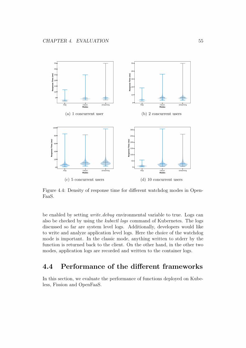
CHAPTER 4. EVALUATION 55
http classic streamingModes
5
10
15
20
25
30
35
Resp
onse
Tim
e (m
s)
(a) 1 concurrent user
http classic streamingModes
0
10
20
30
40
50
Resp
onse
Tim
e (m
s)
(b) 2 concurrent users
http classic streamingModes
0
20
40
60
80
100
Resp
onse
Tim
e (m
s)
(c) 5 concurrent users
http classic streamingModes
0
50
100
150
200
250
300Re
spon
se T
ime
(ms)
(d) 10 concurrent users
Figure 4.4: Density of response time for different watchdog modes in Open-FaaS.
be enabled by setting write debug environmental variable to true. Logs canalso be checked by using the kubectl logs command of Kubernetes. The logsdiscussed so far are system level logs. Additionally, developers would liketo write and analyze application level logs. Here the choice of the watchdogmode is important. In the classic mode, anything written to stderr by thefunction is returned back to the client. On the other hand, in the other twomodes, application logs are recorded and written to the container logs.
4.4 Performance of the different frameworks
In this section, we evaluate the performance of functions deployed on Kube-less, Fission and OpenFaaS.
CHAPTER 4. EVALUATION 56
4.4.1 Setup
We evaluate the performance of the three serverless frameworks with con-currency as high as 100 and the function replica count as high as 50. Thefunction replica counts are kept fixed and no scaling is used. The setup usedin the previous experiment was not sufficient for this experiment. Thus, weuse GKE with the necessary computing resources.
GKE Setup
In GKE, we use Kubernetes version 1.10.4-gke.2 (latest version available atthe time of the experiment). Three worker nodes are used in the cluster, eachnode having 2 vCPUs and 7.5 GB memory. We use Container-Optimized OSas the operating system for the worker nodes. This operating system is opti-mized for running containers and Kubernetes on Google Cloud Platform [6].The cluster is setup in the europe-north1 15 region and all the nodes are lo-cated in zone a. We also set up a VM instance to invoke the functionsdeployed on the GKE cluster. The instance is setup in the same zone asthe GKE cluster to minimize network latency. The instance has 2 vCPUs,7.5 GB memory and ran Debian GNU/Linux 9.4 (stretch) OS.
OpenFaaS installation
We follow the same steps as described in Section 4.3.1 for deploying Open-FaaS. However, we use only the HTTP watchdog mode. This is motivated bythe results in Section 4.3.2 which indicate that HTTP mode performs betterthan the other modes.
Kubeless installation
We follow the steps outlined in the official Kubeless Quick Start16 for in-stalling Kubeless on GKE. We deploy Kubeless v1.0.0-alpha.6 with RoleBased Access Control (RBAC) enabled. First, we create the kubeless names-pace and install the kubeless controller. Following this, we install componentsrequired for exposing Kubeless function outside the GKE cluster. Kube-less uses Kubernetes Ingress17 to provide routing for the functions. We usethe Nginx Ingress controller by following the instructions in the InstallationGuide18. Next the functions are deployed and they are scaled to a fixed
15https://cloud.google.com/compute/docs/regions-zones16https://kubeless.io/docs/quick-start/17https://kubernetes.io/docs/concepts/services-networking/ingress/18https://kubernetes.io/docs/concepts/services-networking/ingress/

CHAPTER 4. EVALUATION 57
replica size. Finally, triggers19 are created for the functions to expose themoutside the GKE cluster.
Fission installation
We follow the steps outlined in the official Fission Installation Guide20 forinstalling Fission on GKE. We then create an environment for Go, pack-age, route and the actual function. Environments contains the informationrelated to language and runtime for our function. The package provides amechanism to build the function from source code [13]. Routes are created toinvoke Fission functions through HTTP. Finally, the functions are created bydefining the appropriate minscale and maxscale. Though we can use eitherpool based executor and newdeploy, we chose the newdeploy executor [7] asthis supports autoscaling of functions.
4.4.2 Results
Figure 4.5 shows the average response time of the functions in the threeconsidered frameworks. The figure reports the average values obtained fromten iterations as well as the corresponding standard deviations, shown aswhiskers in the plots. We observe that the response time is lowest for Kube-less and highest for Fission. The difference in the response time increaseswith more load, i.e., as the concurrency of requests increases. We believe thelower performance of Fission is due to the router component through whichall HTTP requests are routed. On the other hand, Kubeless relies on nativeKubernetes components wherever possible. For instance, Kubeless uses Ku-bernetes ingress for exposing function outside the Kubernetes cluster. Ourexperiments indicate that the performance using an ingress is better thanthe other approaches. The response time for OpenFaaS is larger than thatof Kubeless. However, they are very close to each other. Moreover, Open-FaaS is not affected by the performance degradation seen in Fission at higherloads, specifically for 50 and 100 concurrent users.
We also monitor the response codes returned by the function invoca-tions. Since the functions are invoked by using HTTP triggers, we trackall responses with a response code of 2xx as successful. This information isobtained from the Apache benchmark tool. Table 4.3 presents the successratio of all function invocations for the scenarios described above. We notethat Kubeless has a 100% success ratio across all scenarios (i.e., all HTTPresponses were successfully received). The success rate for OpenFaaS is less
19https://kubeless.io/docs/http-triggers/20https://docs.fission.io/0.8.0/installation/installation/

CHAPTER 4. EVALUATION 58
1 5 10 20 50 100Concurrent Users
0
50
100
150
200
250
Avg.
Res
pons
e Ti
me
(ms)
Function Replicas - 1FissionKubelessOpenFaas
(a) 1 replica
1 5 10 20 50 100Concurrent Users
0
50
100
150
200
250
Avg.
Res
pons
e Ti
me
(ms)
Function Replicas - 5FissionKubelessOpenFaas
(b) 5 replicas
1 5 10 20 50 100Concurrent Users
0
50
100
150
200
250
300
Avg.
Res
pons
e Ti
me
(ms)
Function Replicas - 25FissionKubelessOpenFaas
(c) 25 replicas
1 5 10 20 50 100Concurrent Users
0
50
100
150
200
250
300Av
g. R
espo
nse
Tim
e (m
s)
Function Replicas - 50FissionKubelessOpenFaas
(d) 50 replicas
Figure 4.5: Average response time (in milliseconds) for different serverlessframeworks with 1, 5, 25 and 50 function replicas.
than 97% for 100 concurrent users for 5, 25 and 50 function replicas. Wealso note that for OpenFaaS with 50 and 100 concurrent users, the successratio with 1 function replica is higher than with 5, 25 or 50 function replicas.This may be attributed to the design of OpenFaaS. Every function call hasto go through the gateway, faas-netes, watchdog before reaching the func-tion. This introduces multiple hops and multiple points of failure. Whenthere are more function replicas, the gateway and faas-netes may introducebottlenecks leading to the observed increase in failed responses. Fission hasa stable success ratio across all concurrent users and replica counts. Though,the success rate has decreased with the increase in concurrent users, the dif-ference is minimal. In comparison to OpenFaaS, its performance in case of50 and 100 concurrent users have been better. This may be because Fissionhas fewer hops during function invocation in comparison to OpenFaaS.

CHAPTER 4. EVALUATION 59
Concurrent users# rep. 1 5 10 20 50 100
Kubeless
1 100.00 100.00 100.00 100.00 100.00 100.005 100.00 100.00 100.00 100.00 100.00 100.0025 100.00 100.00 100.00 100.00 100.00 100.0050 100.00 100.00 100.00 100.00 100.00 100.00
Fission
1 100.00 99.90 99.84 99.78 99.54 99.325 100.00 99.89 99.84 99.78 99.64 99.4525 100.00 99.89 99.85 99.77 99.48 99.1950 100.00 99.88 99.81 99.79 99.61 99.31
OpenFaaS
1 99.95 99.99 99.91 99.58 98.73 98.275 100.00 99.99 99.93 99.61 97.66 96.2325 100.00 100.00 99.92 99.67 97.76 96.0450 100.00 100.00 99.93 99.61 97.48 96.52
Table 4.3: Success ratio (in %) of all requests for different serverless frame-works.

Chapter 5
Conclusion
Over the years, server-side computing has evolved from bare metal serversto virtualization and most recently to serverless computing. In this thesis,we presented a serverless computing framework based on Kubernetes. Wediscussed various use cases where serverless computing is ideal. Our mainmotivation for this work has been to set up a custom serverless computinginfrastructure instead of using the solutions provided by public cloud serviceproviders. This can help to bring the many benefits of serverless computing tothe private cloud. We carried out a feature evaluation of open source server-less computing solutions: Kubeless, OpenWhisk, Fission and OpenFaaS. Interms of features, we found OpenFaaS to be the most flexible in terms ofsupport for multiple container orchestrators and multiple languages. It alsohas the largest GitHub community based on the number of stars and forks.
Next, we evaluated a few serverless computing frameworks based on Ku-bernetes. To this end, we set up three different solutions: OpenFaaS, Kube-less and Fission. We evaluated the ease of developing and deploying functionson these frameworks. We also discussed how the cluster can be monitoredthrough both system and application logs. We then evaluated the differentmodes of invoking functions in OpenFaaS. We concluded that the HTTPmode has the lowest response time and used this mode in the rest of theevaluation. Finally, we compared the performance of the three consideredserverless frameworks. We found that Kubeless has the best performanceamong the three frameworks, both in terms of response time and ratio ofsuccessful responses.
The concepts presented in this thesis can be extended in the followingways.
• In our experiments, we have a maximum of three worker nodes and asingle master node. This can be extended with more master nodes andworker nodes to provide high availability and more processing power.
60

CHAPTER 5. CONCLUSION 61
An interesting avenue for future research would be a performance com-parison with commercial solutions from cloud providers.
• OpenFaaS provides functionality for asynchronous function calls andevent based processing. The frameworks can be extended to supportCloud Events. Cloud Events is a specification by Cloud Native Com-puting Foundation with an aim to standardize event description so thatit can be consumed across multiple platforms [4].
• Our work can be extended to IoT gateways which is an interestinguse case for serverless computing. In fact, IoT gateways have limitedcomputing capability and need to serve bursty workloads. Serverlesscomputing can efficiently manage this kind of workload [5]. The ar-chitecture used in this thesis can be replicated on an IoT gateway.Moreover, serverless computing can be used along with gateway as aservice [65], where serverless computing can be used to deploy variousfunctions as services on an IoT gateway. Thus, a proof of concept canbe developed for a serverless computing framework on an IoT gateway.

Bibliography
[1] About storage drivers — docker documentation. https://docs.
docker.com/storage/storagedriver/#images-and-layers. (Accessed on02/26/2018).
[2] Apache openwhisk is a serverless, open source cloud platform. https:
//openwhisk.apache.org/. (Accessed on 04/27/2018).
[3] apache/incubator-openwhisk: Apache openwhisk is a serverless event-based programming service and an apache incubator project. https:
//github.com/apache/incubator-openwhisk. (Accessed on 03/21/2018).
[4] Cloudevents. https://cloudevents.io/. (Accessed on 06/17/2018).
[5] CNCF serverless whitepaper v1.0. https://github.com/cncf/wg-
serverless/tree/master/whitepaper. (Accessed on 02/18/2018).
[6] Container-optimized os — google cloud. https://cloud.google.com/
container-optimized-os/. (Accessed on 07/05/2018).
[7] Controlling function execution :: Serverless functions for kubernetes.https://docs.fission.io/0.8.0/concepts/executor/. (Accessed on07/05/2018).
[8] Create functions - openfaas. https://docs.openfaas.com/cli/
templates/. (Accessed on 06/27/2018).
[9] Create functions - openfaas. https://docs.openfaas.com/cli/
templates/#43-use-your-own-templates. (Accessed on 06/14/2018).
[10] Custom resources - kubernetes. https://kubernetes.io/docs/
concepts/extend-kubernetes/api-extension/custom-resources/. (Ac-cessed on 06/27/2018).
62

BIBLIOGRAPHY 63
[11] Dynamodb streams and aws lambda triggers - amazon dy-namodb. https://docs.aws.amazon.com/amazondynamodb/latest/
developerguide/Streams.Lambda.html. (Accessed on 06/27/2018).
[12] Enabling istio on fission :: Serverless functions for kubernetes. https://docs.fission.io/0.8.0/tutorial/enabling-istio-on-fission/. (Ac-cessed on 06/27/2018).
[13] Fission :: Serverless functions for kubernetes. https://docs.fission.
io/. (Accessed on 06/26/2018).
[14] Fission: a faas for kubernetes @ scale16x // speaker deck.https://speakerdeck.com/soamvasani/fission-a-faas-for-
kubernetes-at-scale16x. (Accessed on 03/27/2018).
[15] fission/fission: Fast serverless functions for kubernetes. https://github.com/fission/fission. (Accessed on 03/26/2018).
[16] fission/fission-workflows: Workflows for fission: Fast, reliable andlightweight function composition for serverless functions. https://
github.com/fission/fission-workflows. (Accessed on 03/26/2018).
[17] Gateway - openfaas. https://docs.openfaas.com/architecture/
gateway/. (Accessed on 05/26/2018).
[18] How nodes works. https://docs.docker.com/engine/swarm/how-swarm-mode-works/nodes/. (Accessed on 26/01/2018).
[19] How swarm works. https://docs.docker.com/engine/swarm/how-
swarm-mode-works/services/. (Accessed on 26/01/2018).
[20] How to keep your lambda functions warm ? a cloud guru.https://read.acloud.guru/how-to-keep-your-lambda-functions-
warm-9d7e1aa6e2f0. (Accessed on 06/27/2018).
[21] I heard about the 8 fallacies of distributed computing few years ago.https://www.rgoarchitects.com/Files/fallacies.pdf. (Accessed on06/27/2018).
[22] incubator-openwhisk-deploy-kube/readme.md at mas-ter · apache/incubator-openwhisk-deploy-kube. https:
//github.com/apache/incubator-openwhisk-deploy-kube/blob/
0bc2e16478f5bceffc717a82ce581f82a2549344/README.md#setting-
up-kubernetes. (Accessed on 06/27/2018).

BIBLIOGRAPHY 64
[23] incubator-openwhisk/metrics.md at ee2dd9719ff09818adffd3a02707ca24118b8afa· apache/incubator-openwhisk. https://
github.com/apache/incubator-openwhisk/blob/
ee2dd9719ff09818adffd3a02707ca24118b8afa/docs/metrics.md. (Ac-cessed on 06/27/2018).
[24] Kubeless. http://kubeless.io/docs/architecture/. (Accessed on03/18/2018).
[25] Kubeless. http://kubeless.io/docs/. (Accessed on 03/18/2018).
[26] Kubernetes cloud controller manager - kubernetes. https:
//kubernetes.io/docs/tasks/administer-cluster/running-cloud-
controller/. (Accessed on 06/26/2018).
[27] Kubernetes components. https://kubernetes.io/docs/concepts/
overview/components/. (Accessed on 02/02/2018).
[28] Openfaas. https://docs.openfaas.com/. (Accessed on 06/26/2018).
[29] openfaas/faas: Openfaas - serverless functions made simple for docker& kubernetes. https://github.com/openfaas/faas. (Accessed on03/27/2018).
[30] Serverless by the numbers: 2018 report. https://serverless.com/
blog/serverless-by-the-numbers-2018-data-report/. (Accessed on06/26/2018).
[31] Serverless computing.pdf. https://www2.deloitte.com/content/
dam/Deloitte/tr/Documents/technology-media-telecommunications/
Serverless%20Computing.pdf. (Accessed on 06/27/2018).
[32] Source code organization and your development workflow :: Serverlessfunctions for kubernetes. https://docs.fission.io/0.8.0/tutorial/
developer-workflow/. (Accessed on 07/05/2018).
[33] Vmware + openfaas - one month in - vmware open sourceblog. https://blogs.vmware.com/opensource/2018/03/20/vmware-
openfaas-alex-ellis/. (Accessed on 06/27/2018).
[34] Watchdog - openfaas. https://docs.openfaas.com/architecture/
watchdog/. (Accessed on 05/27/2018).
[35] What is kubernetes? https://kubernetes.io/docs/concepts/
overview/what-is-kubernetes/. (Accessed on 01/11/2017).

BIBLIOGRAPHY 65
[36] Who is using microservices? http://microservices.io/articles/
whoisusingmicroservices.html. (Accessed on 02/25/2018).
[37] Adzic, G., and Chatley, R. Serverless computing: economic andarchitectural impact. In Proceedings of the 2017 11th Joint Meeting onFoundations of Software Engineering (2017), ACM, pp. 884–889.
[38] Anderson, C. Docker [software engineering]. IEEE Software 32, 3(2015), 102–c3.
[39] Armbrust, M., Fox, A., Griffith, R., Joseph, A. D., Katz, R.,Konwinski, A., Lee, G., Patterson, D., Rabkin, A., Stoica,I., et al. A view of cloud computing. Communications of the ACM53, 4 (2010), 50–58.
[40] Baldini, I., Castro, P., Chang, K., Cheng, P., Fink, S.,Ishakian, V., Mitchell, N., Muthusamy, V., Rabbah, R.,Slominski, A., et al. Serverless computing: Current trends andopen problems. In Research Advances in Cloud Computing. Springer,2017, pp. 1–20.
[41] Baldini, I., Castro, P., Cheng, P., Fink, S., Ishakian, V.,Mitchell, N., Muthusamy, V., Rabbah, R., and Suter, P.Cloud-native, event-based programming for mobile applications. In Pro-ceedings of the International Conference on Mobile Software Engineeringand Systems (2016), ACM, pp. 287–288.
[42] Barham, P., Dragovic, B., Fraser, K., Hand, S., Harris, T.,Ho, A., Neugebauer, R., Pratt, I., and Warfield, A. Xen andthe art of virtualization. In ACM SIGOPS operating systems review(2003), vol. 37, ACM, pp. 164–177.
[43] Bellard, F. Qemu, a fast and portable dynamic translator.In USENIX Annual Technical Conference, FREENIX Track (2005),pp. 41–46.
[44] Burns, B., Grant, B., Oppenheimer, D., Brewer, E., andWilkes, J. Borg, omega, and kubernetes. Queue 14, 1 (2016), 10.
[45] Castro, P., Ishakian, V., Muthusamy, V., and Slominski, A.Serverless programming (function as a service). In Distributed Com-puting Systems (ICDCS), 2017 IEEE 37th International Conference on(2017), IEEE, pp. 2658–2659.

BIBLIOGRAPHY 66
[46] Che, J., Shi, C., Yu, Y., and Lin, W. A synthetical performanceevaluation of openvz, xen and kvm. In Services Computing Conference(APSCC), 2010 IEEE Asia-Pacific (2010), IEEE, pp. 587–594.
[47] Claburn, T. Lambda and serverless is one of the worst formsof proprietary lock-in we’ve ever seen in the history of human-ity. https://www.theregister.co.uk/2017/11/06/coreos_kubernetes_
v_world/, Nov 2017. (Accessed on 02/21/2018).
[48] Cockcroft, A. Evolution of business logic from monoliths throughmicroservices, to functions. https://read.acloud.guru/ff464b95a44d,2017. (Accessed on 01/11/2017).
[49] Creasy, R. J. The origin of the vm/370 time-sharing system. IBMJournal of Research and Development 25, 5 (1981), 483–490.
[50] Dmitry, N., and Manfred, S.-S. On micro-services architecture.International Journal of Open Information Technologies 2, 9 (2014).
[51] Dragoni, N., Giallorenzo, S., Lafuente, A. L., Mazzara, M.,Montesi, F., Mustafin, R., and Safina, L. Microservices: yester-day, today, and tomorrow. arXiv preprint arXiv:1606.04036 (2016).
[52] Dua, R., Raja, A. R., and Kakadia, D. Virtualization vs con-tainerization to support paas. In Cloud Engineering (IC2E), 2014 IEEEInternational Conference on (2014), IEEE, pp. 610–614.
[53] Felter, W., Ferreira, A., Rajamony, R., and Rubio, J. An up-dated performance comparison of virtual machines and linux containers.In Performance Analysis of Systems and Software (ISPASS), 2015 IEEEInternational Symposium On (2015), IEEE, pp. 171–172.
[54] Fowler, M., and Lewis, J. Microservices. https://martinfowler.
com/articles/microservices.html. (Accessed on 02/09/2018).
[55] Fox, G. C., Ishakian, V., Muthusamy, V., and Slominski, A.Status of serverless computing and function-as-a-service (faas) in indus-try and research. arXiv preprint arXiv:1708.08028 (2017).
[56] Garriga, M. Towards a taxonomy of microservices architectures. InInternational Conference on Software Engineering and Formal Methods(2017), Springer, pp. 203–218.

BIBLIOGRAPHY 67
[57] Goldberg, R. P. Architectural principles for virtual computer sys-tems. Tech. rep., HARVARD UNIV CAMBRIDGE MA DIV OF EN-GINEERING AND APPLIED PHYSICS, 1973.
[58] Honeycutt, J. Microsoft virtual pc 2004 technical overview. Mi-crosoft, Nov (2003).
[59] Jaramillo, D., Nguyen, D. V., and Smart, R. Leveraging mi-croservices architecture by using docker technology. In SoutheastCon,2016 (2016), IEEE, pp. 1–5.
[60] Javed, A., et al. Container-based iot sensor node on raspberry piand the kubernetes cluster framework.
[61] Joy, A. M. Performance comparison between linux containers and vir-tual machines. In Computer Engineering and Applications (ICACEA),2015 International Conference on Advances in (2015), IEEE, pp. 342–346.
[62] Marston, S., Li, Z., Bandyopadhyay, S., Zhang, J., and Ghal-sasi, A. Cloud computing?the business perspective. Decision supportsystems 51, 1 (2011), 176–189.
[63] McGrath, G., and Brenner, P. R. Serverless computing: Design,implementation, and performance. In Distributed Computing SystemsWorkshops (ICDCSW), 2017 IEEE 37th International Conference on(2017), IEEE, pp. 405–410.
[64] Morabito, R., Kjallman, J., and Komu, M. Hypervisors vs.lightweight virtualization: a performance comparison. In Cloud Engi-neering (IC2E), 2015 IEEE International Conference on (2015), IEEE,pp. 386–393.
[65] Morabito, R., Petrolo, R., Loscrı, V., and Mitton, N. En-abling a lightweight edge gateway-as-a-service for the internet of things.In Network of the Future (NOF), 2016 7th International Conference onthe (2016), IEEE, pp. 1–5.
[66] Muller, A., and Wilson, S. Virtualization with vmware esx server.
[67] Nastic, S., Rausch, T., Scekic, O., Dustdar, S., Gusev, M.,Koteska, B., Kostoska, M., Jakimovski, B., Ristov, S., andProdan, R. A serverless real-time data analytics platform for edgecomputing. IEEE Internet Computing 21, 4 (2017), 64–71.

BIBLIOGRAPHY 68
[68] Ongaro, D., and Ousterhout, J. K. In search of an understandableconsensus algorithm. In USENIX Annual Technical Conference (2014),pp. 305–319.
[69] Popek, G. J., and Goldberg, R. P. Formal requirements for vir-tualizable third generation architectures. Communications of the ACM17, 7 (1974), 412–421.
[70] Preeth, E., Mulerickal, F. J. P., Paul, B., and Sastri, Y.Evaluation of docker containers based on hardware utilization. In Con-trol Communication & Computing India (ICCC), 2015 InternationalConference on (2015), IEEE, pp. 697–700.
[71] Rensin, D. K. Kubernetes-scheduling the future at cloud scale.
[72] Reshetova, E., Karhunen, J., Nyman, T., and Asokan, N.Security of os-level virtualization technologies. In Nordic Conference onSecure IT Systems (2014), Springer, pp. 77–93.
[73] Robin, J. S., Irvine, C. E., et al. Analysis of the intel pentium’sability to support a secure virtual machine monitor. Proceedings of the9th USENIX Security Symposium, Denver, CO.
[74] Shillaker, S. A provider-friendly serverless framework for latency-critical applications. http://conferences.inf.ed.ac.uk/EuroDW2018/
papers/eurodw18-Shillaker.pdf. (Accessed on 06/30/2018).
[75] Singleton, A. The economics of microservices. IEEE Cloud Comput-ing 3, 5 (2016), 16–20.
[76] Soltesz, S., Potzl, H., Fiuczynski, M. E., Bavier, A., and Pe-terson, L. Container-based operating system virtualization: a scal-able, high-performance alternative to hypervisors. In ACM SIGOPSOperating Systems Review (2007), vol. 41, ACM, pp. 275–287.
[77] Sugerman, J., Venkitachalam, G., and Lim, B.-H. Virtualizingi/o devices on vmware workstation’s hosted virtual machine monitor. InUSENIX Annual Technical Conference, General Track (2001), pp. 1–14.
[78] Velte, A., and Velte, T. Microsoft virtualization with Hyper-V.McGraw-Hill, Inc., 2009.
[79] Verma, A., Pedrosa, L., Korupolu, M., Oppenheimer, D.,Tune, E., and Wilkes, J. Large-scale cluster management at google

BIBLIOGRAPHY 69
with borg. In Proceedings of the Tenth European Conference on Com-puter Systems (2015), ACM, p. 18.
[80] Xavier, M. G., Neves, M. V., Rossi, F. D., Ferreto, T. C.,Lange, T., and De Rose, C. A. Performance evaluation of container-based virtualization for high performance computing environments. InParallel, Distributed and Network-Based Processing (PDP), 2013 21stEuromicro International Conference on (2013), IEEE, pp. 233–240.

Appendix A
Fission
A.1 Function code
package main
import (” fmt”” net / http ”
)
// Handler i s the entry po in t f o r t h i s f i s s i o n func t i onfunc Handler (w http . ResponseWriter , r ∗http . Request ) {
body , := i o u t i l . ReadAll ( r . Body)message := fmt . S p r i n t f ( ” He l lo world , input was : %s ” , string (
body ) )w. Write ( [ ] byte ( message ) )
}
A.2 Examples of Commands
Below script creates a new go environment.
$ fission env create --name go --image fission/go-env:0.8.0 –builderfission/go-builder:0.8.0
Below script creates a new function using the environment created above.
$ fission function create --name hello --env go --src hello.go --entrypointHandler --minscale 5 –maxscale 5 –executortype newdeploy
70

Appendix B
Kubeless
B.1 Function code
package kube l e s s
import (” fmt”
” github . com/ kube l e s s / kube l e s s /pkg/ f u n c t i o n s ”)
func Handler ( event f u n c t i o n s . Event , context f u n c t i o n s . Context )( string , error ) {
var e r r errormessage := fmt . S p r i n t f ( ” He l lo world , input was : %s ” , event .
Data )return message , e r r
}
B.2 Examples of Commands
Below script creates a new function.
$ kubeless function deploy hello --runtime go1.10 --handler hello.Handler--from-file hello.go
71

Appendix C
OpenFaaS
C.1 Create a new function
The below script is used to create a new function environment. In the belowscript, faas-cli is the command, helloworld is the name of the function and gois the language. In OpenFaaS, the language is defined by a template. Usercan build their own custom templates and give it a custom name. OpenFaaSalso has a predefined set of templates [9].
$ faas-cli new helloworld --lang go
C.1.1 Auto generated function code
Below is an example of a code generated by use of the above script.
package main
import ”fmt”
func main ( ) {fmt . Println ( ” He l lo World ! ” )
}
72

APPENDIX C. OPENFAAS 73
C.1.2 Sample yml file for OpenFaaS functions
prov ide r :name : f a a sgateway : http : // 172 .42 .42 .102 :31112/
f u n c t i o n s :fun1 :
lang : go−streaminghandler : . / fun1image : images . example . com/ fun1s e c r e t s :− image−regenvironment :
wr i te debug : fa l seread debug : fa l se
l a b e l s :”com . openfaas . s c a l e . min” : ”1””com . openfaas . s c a l e . max” : ”100”
f u n c t i o n s :fun2 :
lang : gohandler : . / fun2image : images . example . com/ fun2s e c r e t s :− image−regenvironment :
wr i te debug : fa l seread debug : fa l se
l a b e l s :”com . openfaas . s c a l e . min” : ”1””com . openfaas . s c a l e . max” : ”100”
C.2 Deploy function
Functions in OpenFaaS are deployed by using the below three commands.
The build command builds the Docker image in the local system or the CIbuild server as may be the case.
$ faas-cli build -f template.yml
The push command pushes the Docker image to the image repository.
$ faas-cli push -f template.yml

APPENDIX C. OPENFAAS 74
The deploy command deploys the image as a function.
$ faas-cli deploy -f template.yml
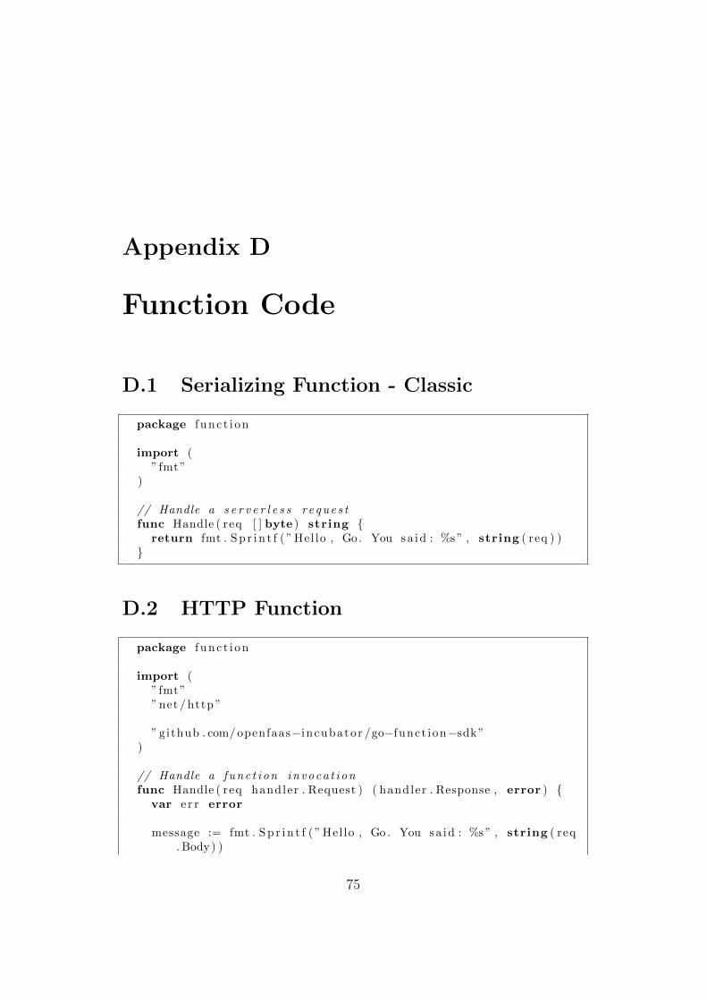
Appendix D
Function Code
D.1 Serializing Function - Classic
package f unc t i on
import (” fmt”
)
// Handle a s e r v e r l e s s r e que s tfunc Handle ( req [ ] byte ) string {
return fmt . S p r i n t f ( ” Hel lo , Go . You sa id : %s ” , string ( req ) )}
D.2 HTTP Function
package f unc t i on
import (” fmt”” net / http ”
” github . com/ openfaas−incubator /go−funct ion−sdk”)
// Handle a func t i on invoca t i onfunc Handle ( req handler . Request ) ( handler . Response , error ) {
var e r r error
message := fmt . S p r i n t f ( ” Hel lo , Go . You sa id : %s ” , string ( req. Body) )
75

APPENDIX D. FUNCTION CODE 76
return handler . Response{Body : [ ] byte ( message ) ,StatusCode : http . StatusOK ,
} , e r r}
D.3 Streaming Function
package f unc t i on
import (” fmt”
)
// Handle a s e r v e r l e s s r e que s tfunc Handle ( req [ ] byte ) string {
return fmt . S p r i n t f ( ” Hel lo , Go . You sa id : %s ” , string ( req ) )}