Evaluation of Polymer Membrane Deformable Mirrors … · Peak Power Laser Machining Applications...
14
Copyright 2010 Society of Photo-Optical Instrumentation Engineers. One print or electronic copy may be made for personal use only. Systematic reproduction and distribution, duplication of any material in this paper for a fee or for commercial purposes, or modification of the content of the paper are prohibited. Evaluation of Polymer Membrane Deformable Mirrors for High Peak Power Laser Machining Applications Justin D. Mansell, Brian G. Henderson, and Gideon Robertson Active Optical Systems, LLC; 2021 Girard Blvd. Suite 150, Albuquerque, NM 87106 ABSTRACT Polymer membrane deformable mirrors offer a low-cost alternative to conventional technology in a wide variety of adaptive optics or laser beam shaping applications. In this paper we evaluate the suitability of two different kinds of polymer membrane deformable mirrors for laser machining. We present results showing that a 12.5-mm diameter nitrocellulose membrane fails near 400 microns of motion. We present results from a demonstration of a high peak power beam shaping and show a new compact laser beam shaping system using a polymer membrane deformable mirror. We evaluate the effect of Q-switched laser radiation on polymer membranes at 355nm and 1060nm. Keywords: Keywords: Membrane Deformable Mirror, Adaptive Optics, Laser Machining, Beam Shaping 1. INTRODUCTION Laser beam shaping is being adopted by some laser manufacturers as a way to provide customers more control over their lasers for laser machining. There are many different ways of implementing a beam shaping system. 1 The most common approach is to leverage a fixed optic that adjusts the spatial phase to cause the intensity profile to change as the beam propagates. Sometimes a second optic is used to compensate the phase. This approach can be very effective and fairly inexpensive, especially in mass-fabrication, but is susceptible to problems due to misalignment and input beam profile changes and is not able to achieve different output beam profiles using a single fixed optic. Dielectric fixed optic beam correctors are also susceptible to chromatic effects, especially with ultrashort pulsed lasers where the spectral bandwidth is significantly large. We chose to pursue using deformable mirrors because of their flexibility and ability to provide engineering control of the beam. By adding control of the beam shaping optic surface, we are able to compensate for aberrations induced by using the device off-axis and non-idealities in the input laser beam profile. Because the device is reflective, it is achromatic and can be used to shape the intensity profile of lasers with a wide spectral bandwidth. In addition to enabling beam shaping, a deformable mirror can compensate for aberrations in the laser and simultaneously move the focal plane along the optical axis to machine over complex surfaces. We have been developing these beam shaping systems for several years leveraging nitrocellulose membranes. In this paper we are reporting on polyimide membrane deformable mirrors and some characterization of both the nitrocecellulose and polyimide deformable mirrors. The characterization includes laser damage, effect of humidity on frequency response of both kinds of membranes, and the ultimate strength of a nitrocellulose membrane due to hydrostatic pressure. We also are reporting on some recent results from beam shaping a high peak power fiber laser. We conclude with some summary remarks and discussion of future work. 2. POLYIMIDE MEMBRANE DEFORMABLE MIRRORS We have been building and selling nitrocellulose membrane deformable mirrors for half of a decade. Figure 1 shows the basic architecture we use for membrane deformable mirrors. These membranes have been successful because they can be manufactured in low volume at an accessible price point ($1500 for a standard ~32-actuator device). Unfortunately, we recently realized that the Figure 1 - Exploded 3D CAD rendering of a basic membrane deformable mirror
Transcript of Evaluation of Polymer Membrane Deformable Mirrors … · Peak Power Laser Machining Applications...

Copyright 2010 Society of Photo-Optical Instrumentation Engineers. One print or electronic copy may be made for personal use only.
Systematic reproduction and distribution, duplication of any material in this paper for a fee or for commercial purposes, or modification of the
content of the paper are prohibited.
Evaluation of Polymer Membrane Deformable Mirrors for High Peak Power Laser Machining Applications
Justin D. Mansell, Brian G. Henderson, and Gideon Robertson
Active Optical Systems, LLC; 2021 Girard Blvd. Suite 150, Albuquerque, NM 87106
ABSTRACT
Polymer membrane deformable mirrors offer a low-cost alternative to conventional technology in a wide variety of
adaptive optics or laser beam shaping applications. In this paper we evaluate the suitability of two different kinds of
polymer membrane deformable mirrors for laser machining. We present results showing that a 12.5-mm diameter
nitrocellulose membrane fails near 400 microns of motion. We present results from a demonstration of a high peak
power beam shaping and show a new compact laser beam shaping system using a polymer membrane deformable
mirror. We evaluate the effect of Q-switched laser radiation on polymer membranes at 355nm and 1060nm.
Keywords: Keywords: Membrane Deformable Mirror, Adaptive Optics, Laser Machining, Beam Shaping
1. INTRODUCTION
Laser beam shaping is being adopted by some laser manufacturers as a way to provide customers more control over their
lasers for laser machining. There are many different ways of implementing a beam shaping system.1 The most common
approach is to leverage a fixed optic that adjusts the spatial phase to cause the intensity profile to change as the beam
propagates. Sometimes a second optic is used to compensate the phase. This approach can be very effective and fairly
inexpensive, especially in mass-fabrication, but is susceptible to problems due to misalignment and input beam profile
changes and is not able to achieve different output beam profiles using a single fixed optic. Dielectric fixed optic beam
correctors are also susceptible to chromatic effects, especially with ultrashort pulsed lasers where the spectral bandwidth
is significantly large.
We chose to pursue using deformable mirrors because of their flexibility and ability to provide engineering control of the
beam. By adding control of the beam shaping optic surface, we are able to compensate for aberrations induced by using
the device off-axis and non-idealities in the input laser beam profile. Because the device is reflective, it is achromatic
and can be used to shape the intensity profile of lasers with a wide spectral bandwidth. In addition to enabling beam
shaping, a deformable mirror can compensate for aberrations in the laser and simultaneously move the focal plane along
the optical axis to machine over complex surfaces.
We have been developing these beam shaping systems for several years leveraging nitrocellulose membranes. In this
paper we are reporting on polyimide membrane deformable mirrors and some characterization of both the
nitrocecellulose and polyimide deformable mirrors. The characterization includes laser damage, effect of humidity on
frequency response of both kinds of membranes, and the ultimate strength of a nitrocellulose membrane due to
hydrostatic pressure. We also are reporting on some recent results
from beam shaping a high peak power fiber laser. We conclude with
some summary remarks and discussion of future work.
2. POLYIMIDE MEMBRANE DEFORMABLE MIRRORS
We have been building and selling nitrocellulose membrane
deformable mirrors for half of a decade. Figure 1 shows the basic
architecture we use for membrane deformable mirrors. These
membranes have been successful because they can be manufactured
in low volume at an accessible price point ($1500 for a standard
~32-actuator device). Unfortunately, we recently realized that the
Figure 1 - Exploded 3D CAD rendering of a
basic membrane deformable mirror
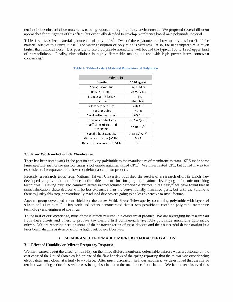
tension in the nitrocellulose material was being reduced in high humidity environments. We proposed several different
approaches for mitigation of this effect, but eventually decided to develop membranes based on a polyimide material.
Table 1 shows select material parameters of polyimide.2 Two of these parameters show an obvious benefit of the
material relative to nitrocellulose. The water absorption of polyimide is very low. Also, the use temperature is much
higher than nitrocellulose. It is possible to use a polyimide membrane well beyond the typical 100 to 125C upper limit
of nitrocellulose. Finally, nitrocellulose is highly flammable making its use with high power lasers somewhat
concerning.3
2.1 Prior Work on Polyimide Membranes
There has been some work in the past on applying polyimide to the manufacture of membrane mirrors. SRS made some
large aperture membrane mirrors using a polyimide material called CP1.4 We investigated CP1, but found it was too
expensive to incorporate into a low-cost deformable mirror product.
Recently, a research group from National Taiwan University published the results of a research effort in which they
developed a polyimide membrane deformable mirror for imaging applications leveraging bulk micromaching
techniques.5 Having built and commercialized micromachined deformable mirrors in the past,
6,7 we have found that in
mass fabrication, these devices will be less expensive than the conventionally machined parts, but until the volume is
there to justify this step, conventionally machined devices are going to be less expensive to manufacture.
Another group developed a sun shield for the James Webb Space Telescope by combining polyimide with layers of
silicon and aluminum.8,9
This work and others demonstrated that it was possible to combine polyimide membrane
technology and engineered coatings.
To the best of our knowledge, none of these efforts resulted in a commercial product. We are leveraging the research all
from these efforts and others to produce the world’s first commercially available polyimide membrane deformable
mirror. We are reporting here on some of the characterization of these devices and their successful demonstration in a
laser beam shaping system based on a high peak power fiber laser.
3. MEMBRANE DEFORMABLE MIRROR CHARACTERIZATION
3.1 Effect of Humidity on Mirror Frequency Response
We first learned about the effect of humidity on the nitrocellulose membrane deformable mirrors when a customer on the
east coast of the United States called on one of the first hot days of the spring reporting that the mirror was experiencing
electrostatic snap-down at a fairly low voltage. After much discussion with our suppliers, we determined that the mirror
tension was being reduced as water was being absorbed into the membrane from the air. We had never observed this
Table 1- Table of select Material Parameters of Polyimide

phenomenon since we do our manufacturing in a fairly controlled environment in Albuquerque, NM, where it is rarely
very humid, as can be seen in Figure 2.10
Having identified humidity as the source of the lack of tension in the mirrors, we decided to characterize the effect of
humidity on deformable mirror temporal frequency response, which can be directly related to mirror tension by,11
T
Df
766.01
where D is the diameter of the membrane, T is the membrane tension in Newtons per meter, and σ is the density of the
membrane material in kg/m2. As an example, a 50 N/m tension on a 0.0143 (10 micron thick) polyimide membrane 2.5
cm in diameter would have a first resonance at 1811 Hz.
Figure 3 shows the experimental setup we used to make our measurements. The experiment was performed in a table
that was enclosed with vinyl curtains to concentrate the humidity. The air conditioning was found to dry the room air so
it had to be turned off to maximize the humidity. When we turned off the air conditioning during our experiments, the
lab temperature increased from 72 º F to nearly 80º F, but was fairly consistent at that level during the testing. We
Figure 2 - Average Humidity of Albuquerque, NM, New York, NY, and Orlando, FL, in 2009
0
10
20
30
40
50
60
70
80
90
100
1/1 2/20 4/11 5/31 7/20 9/8 10/28 12/17
Ave
rage
Hu
mid
ity
(%)
Date (2009)
Albuquerque
New York
Orlando
Figure 3 - Experimental Setup for Measuring Membrane Deformable Mirror Resonance at varying Humidity.
decided to leverage a commercial off the shelf (COTS) vaporizer to add humidity to the air. We used a sensitive digital
temperature and humidity probe to monitor the humidity during our experiments.
We used an AOS high-speed single channel amplifier with a corner frequency of nearly 100 kHz to boost the voltage
from a signal coming from a NI USB 6221 analog output to drive the deformable mirror. We used different electrostatic
pad arrays for this experiment, but connected all the channels using a custom ribbon cable header that kept all the pads at
ground and allowed us to drive the voltage on the mirror membrane directly. We drove the deformable mirror with a
fixed amplitude varying frequency sinusoidal voltage signal. The laser beam that was reflected from the membrane
deformable mirror was sent through a focus of a 500-mm focal length lens. We placed a small iris just before the
tightest focus to create an intensity signal that would be proportional to the beam’s wavefront curvature (effectively a
zero-dimensional curvature sensor). If the iris was placed in a region between the smallest focal length of the system
and the largest focal length, we found that the photodiode saw doubling of the drive frequency. We used the NI 6221
analog input to monitor the signal from a high speed photodiode that was placed in the beam after the iris. We wrote
custom software to create the appropriate drive signal and analyze the photodiode signal.
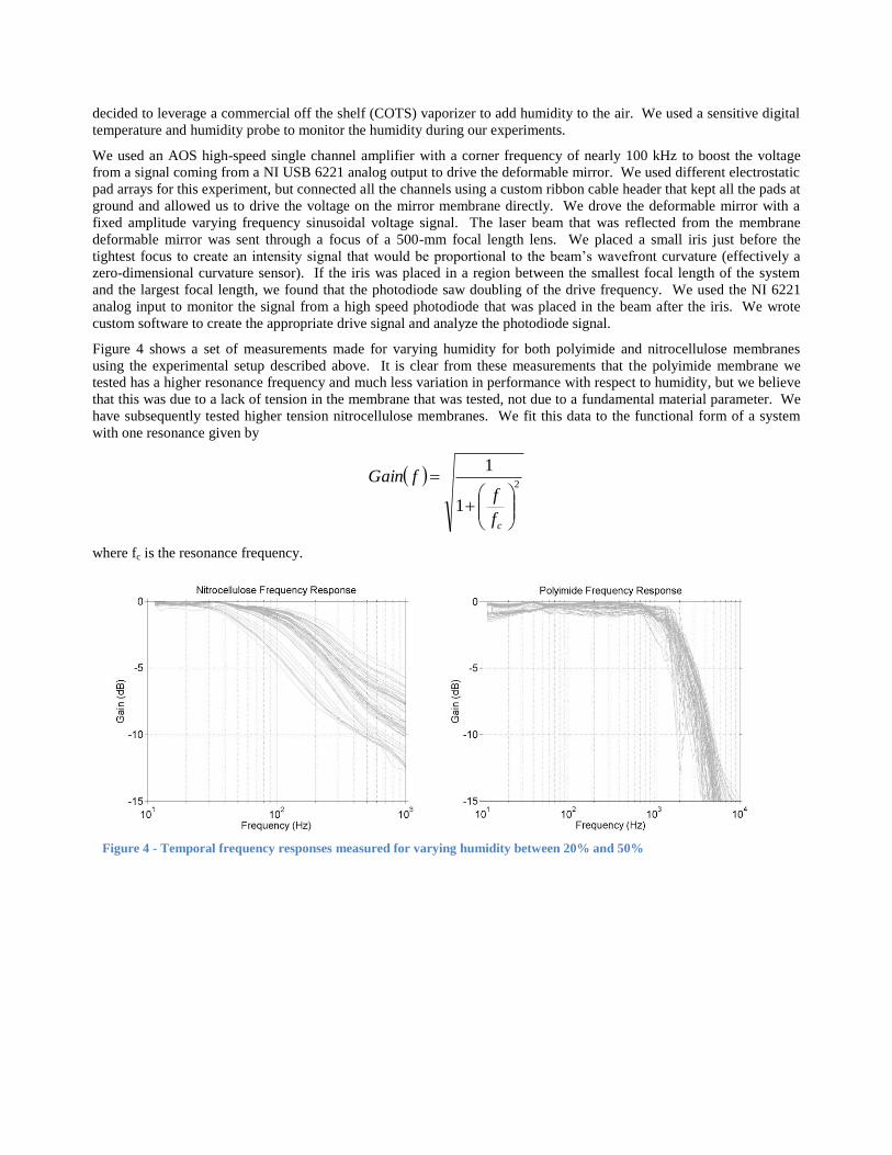
Figure 4 shows a set of measurements made for varying humidity for both polyimide and nitrocellulose membranes
using the experimental setup described above. It is clear from these measurements that the polyimide membrane we
tested has a higher resonance frequency and much less variation in performance with respect to humidity, but we believe
that this was due to a lack of tension in the membrane that was tested, not due to a fundamental material parameter. We
have subsequently tested higher tension nitrocellulose membranes. We fit this data to the functional form of a system
with one resonance given by
2
1
1
cf
ffGain
where fc is the resonance frequency.
Figure 4 - Temporal frequency responses measured for varying humidity between 20% and 50%

Figure 5 shows the extracted corner frequency from the measured temporal frequency response. It is clear from these
measurements that the polyimide membrane has much less frequency response change with respect to humidity.
Overall, we found that the polyimide membranes exhibited almost no significant variation in the corner frequency over a
wide humidity range, but the nitrocellulose membrane had a very significant variation. The overall difference in the
magnitude of the corner frequency was attributed to the membrane tension, not a fundamental difference in the material.
3.2 Ultimate Deformation Evaluation of Nitrocellulose Membranes
From our laboratory experience, we knew that the polymer membranes were robust, but we did not know how much
deformation would be required to cause the membranes to rupture, so we designed an experiment to determine the
failure point. We created a hydrostatic pressure cell with the only flexible element being a 0.5” diameter nitrocellulose
membrane coated with aluminum. Figure 6 shows the manufactured hydrostatic pressure cell that was manufactured
from a PVC tee, hose barb fitting, plexiglass window, and a 0.5” diameter aluminum-coated nitrocellulose membrane.
The cell was assembled using 5-minute epoxy for the connections.
We applied pressure using a COTS bicycle pump and monitored the effective focal length during the experiment. The
mirror membrane ruptured due to a failure of the bond to its frame when the focus was about 1” away from the mirror
surface, corresponding to 31 mil or 800 microns of displacement. Figure 7 shows select images from the movie of the
rupture of the mirror membrane. In these images, an AOS logo is visible in the field of view of the reflection from the
membrane. Initially the bicycle tire pump reduced the pressure in the cell to the point where the membrane was focusing
(a) (b) (c)
Figure 6 - Photographs of the pressure cell with the 0.5" diameter nitrocellulose membrane before (a) and after (b)
rupture and the ruptured membrane on the optical table (c).
Figure 5 - Approximate 3-dB frequencies extracted from a polyimide membrane and a nitrocellulose membrane

on the logo, which was approximately 1.5 meters from the membrane. Then the pressure was increased so significantly
that the logo was no longer resolvable in the imaging system just before rupture.
3.3 Laser Damage Evaluation
Coating Capability
Since we are interested in determining the efficacy of these membrane mirrors to shape laser beams for laser machining
applications, we needed to determine the damage threshold of the mirrors due to high average power laser illumination.
The best way to avoid damage on any mirror is to get a good coating. Unfortunately, the best quality coatings are high
stress which can cause distortion in the mirror surface. To avoid this distortion, we chose to use an electron-beam
evaporated enhanced metal coating. Since we were interested in both 1060nm and 355nm machining wavelengths, we
needed two different coatings. We chose to do a silver coating with 4 layers of dielectric enhancement at the 1060 nm
wavelength, but an aluminum coating with only 2 layers of enhancement at the 355 nm wavelength. Figure 8 shows the
coating reflectivity measured with a spectrometer over the pertinent ranges. According to the spectrometer, the 1060-nm
coating was 99.2% reflective at the laser wavelength, but the 355-nm coating was only 93.1% reflective. The coatings
had very little scatter loss, so most of the energy that was not reflected was absorbed. An error occurred during the first
coating attempt of the polyimide mirror membranes, but a standard acid strip of the coating was successful at removing
the coating without destroying the thin membranes, so a second coating was able to be applied. The mirrors did not
Figure 7 - Images from the movie of the hydrostatic pressure rupture of the 0.5" diameter nitrocellulose membrane
Figure 8 - Spectrometer measurements of the coating reflectivity for each coating
escape damage altogether though. Some of the mirrors had a stain due to insufficient rinse of the etchant. Others had
scratches due to a technician’s attempt to wipe off the mirrors using a clean wipe. We tried to test only the best mirrors
during the damage testing, but cannot guarantee that subsequent testing with fresh membranes may not produce even
higher damage thresholds.
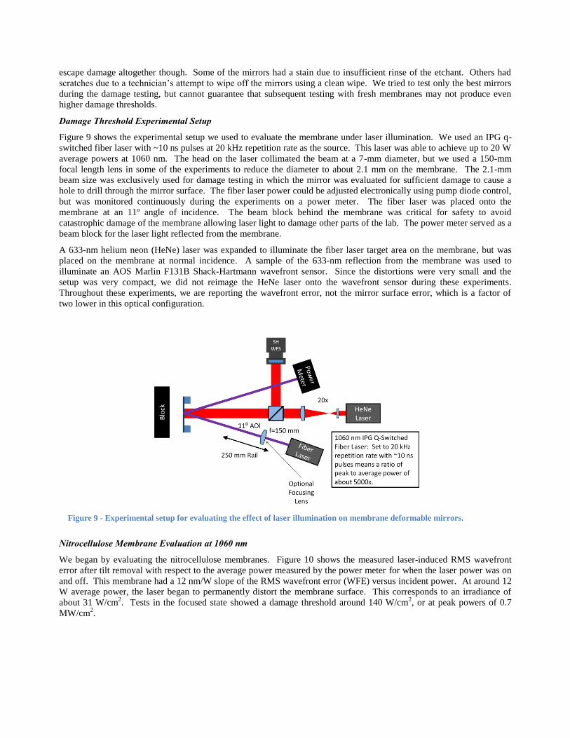
Damage Threshold Experimental Setup
Figure 9 shows the experimental setup we used to evaluate the membrane under laser illumination. We used an IPG q-
switched fiber laser with ~10 ns pulses at 20 kHz repetition rate as the source. This laser was able to achieve up to 20 W
average powers at 1060 nm. The head on the laser collimated the beam at a 7-mm diameter, but we used a 150-mm
focal length lens in some of the experiments to reduce the diameter to about 2.1 mm on the membrane. The 2.1-mm
beam size was exclusively used for damage testing in which the mirror was evaluated for sufficient damage to cause a
hole to drill through the mirror surface. The fiber laser power could be adjusted electronically using pump diode control,
but was monitored continuously during the experiments on a power meter. The fiber laser was placed onto the
membrane at an 11º angle of incidence. The beam block behind the membrane was critical for safety to avoid
catastrophic damage of the membrane allowing laser light to damage other parts of the lab. The power meter served as a
beam block for the laser light reflected from the membrane.
A 633-nm helium neon (HeNe) laser was expanded to illuminate the fiber laser target area on the membrane, but was
placed on the membrane at normal incidence. A sample of the 633-nm reflection from the membrane was used to
illuminate an AOS Marlin F131B Shack-Hartmann wavefront sensor. Since the distortions were very small and the
setup was very compact, we did not reimage the HeNe laser onto the wavefront sensor during these experiments.
Throughout these experiments, we are reporting the wavefront error, not the mirror surface error, which is a factor of
two lower in this optical configuration.
Nitrocellulose Membrane Evaluation at 1060 nm
We began by evaluating the nitrocellulose membranes. Figure 10 shows the measured laser-induced RMS wavefront
error after tilt removal with respect to the average power measured by the power meter for when the laser power was on
and off. This membrane had a 12 nm/W slope of the RMS wavefront error (WFE) versus incident power. At around 12
W average power, the laser began to permanently distort the membrane surface. This corresponds to an irradiance of
about 31 W/cm2. Tests in the focused state showed a damage threshold around 140 W/cm
2, or at peak powers of 0.7
MW/cm2.
Figure 9 - Experimental setup for evaluating the effect of laser illumination on membrane deformable mirrors.
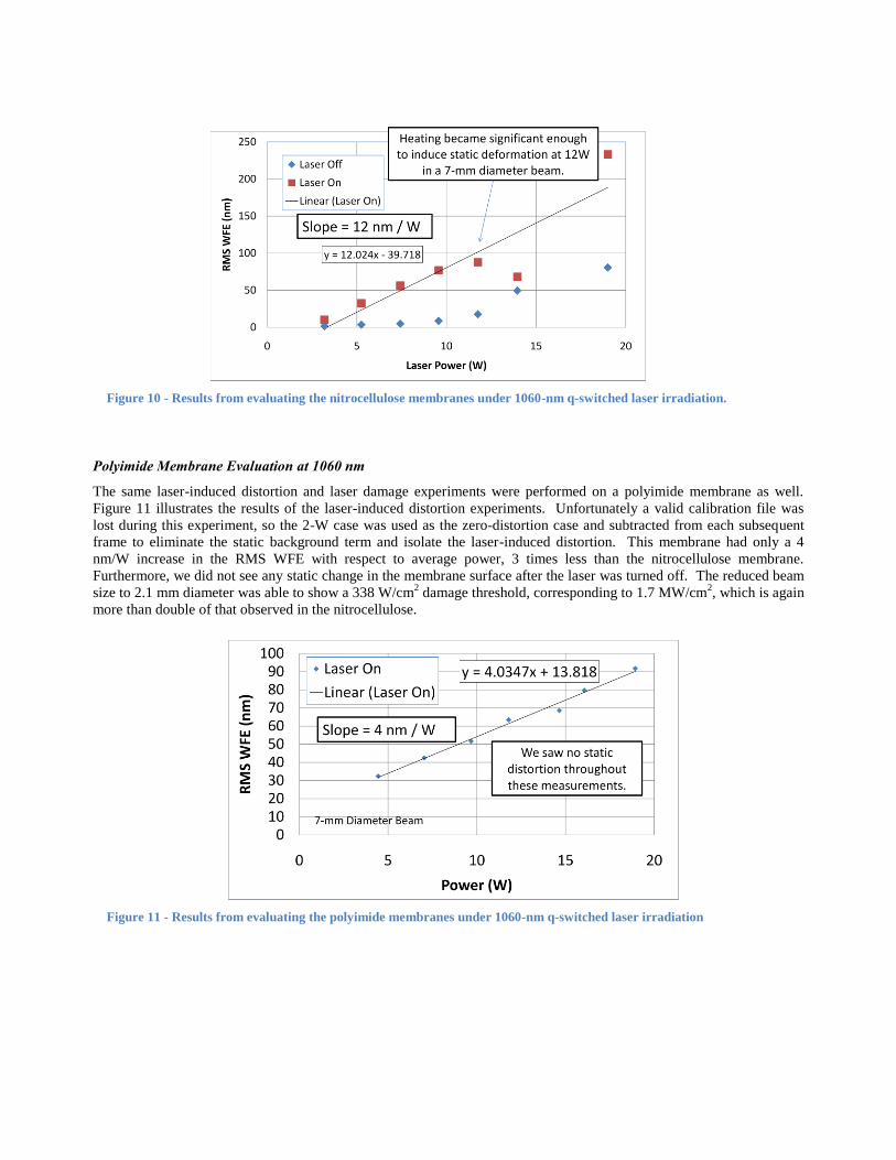
Polyimide Membrane Evaluation at 1060 nm
The same laser-induced distortion and laser damage experiments were performed on a polyimide membrane as well.
Figure 11 illustrates the results of the laser-induced distortion experiments. Unfortunately a valid calibration file was
lost during this experiment, so the 2-W case was used as the zero-distortion case and subtracted from each subsequent
frame to eliminate the static background term and isolate the laser-induced distortion. This membrane had only a 4
nm/W increase in the RMS WFE with respect to average power, 3 times less than the nitrocellulose membrane.
Furthermore, we did not see any static change in the membrane surface after the laser was turned off. The reduced beam
size to 2.1 mm diameter was able to show a 338 W/cm2 damage threshold, corresponding to 1.7 MW/cm
2, which is again
more than double of that observed in the nitrocellulose.
Figure 10 - Results from evaluating the nitrocellulose membranes under 1060-nm q-switched laser irradiation.
Figure 11 - Results from evaluating the polyimide membranes under 1060-nm q-switched laser irradiation
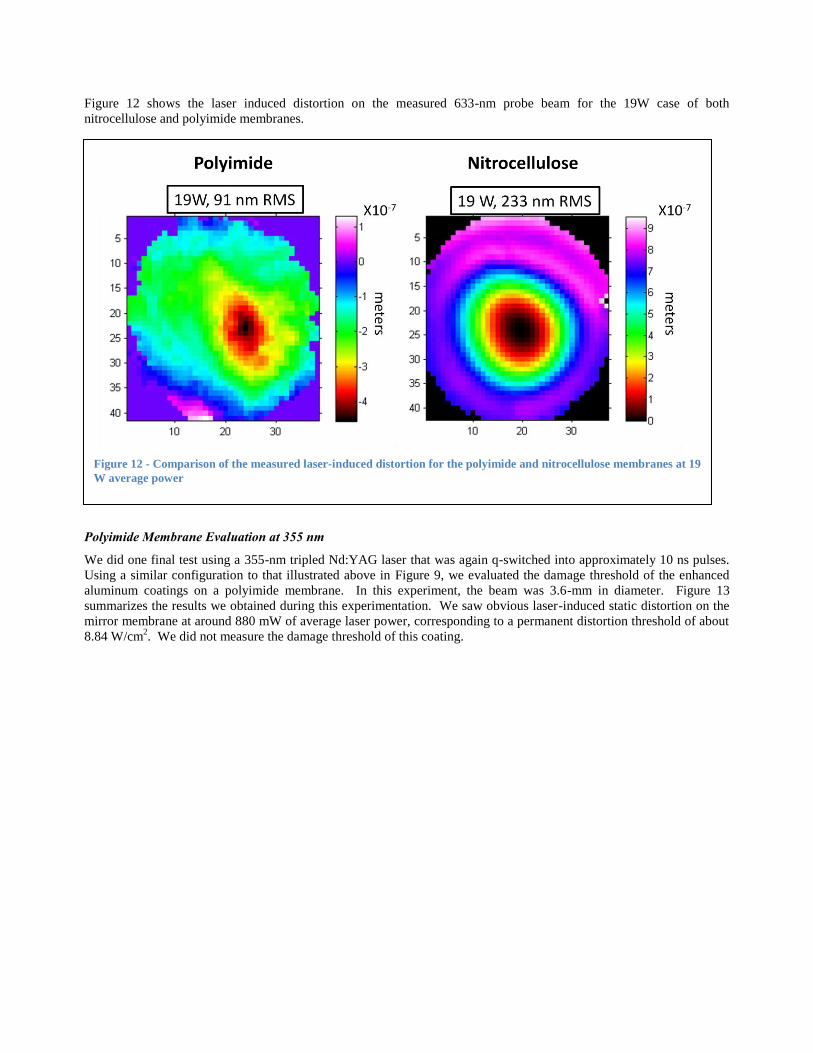
Figure 12 shows the laser induced distortion on the measured 633-nm probe beam for the 19W case of both
nitrocellulose and polyimide membranes.
Polyimide Membrane Evaluation at 355 nm
We did one final test using a 355-nm tripled Nd:YAG laser that was again q-switched into approximately 10 ns pulses.
Using a similar configuration to that illustrated above in Figure 9, we evaluated the damage threshold of the enhanced
aluminum coatings on a polyimide membrane. In this experiment, the beam was 3.6-mm in diameter. Figure 13
summarizes the results we obtained during this experimentation. We saw obvious laser-induced static distortion on the
mirror membrane at around 880 mW of average laser power, corresponding to a permanent distortion threshold of about
8.84 W/cm2. We did not measure the damage threshold of this coating.
Figure 12 - Comparison of the measured laser-induced distortion for the polyimide and nitrocellulose membranes at 19
W average power

Laser Damage Summary
Table 2 summarizes the key numerical results we measured for laser damage and laser-induced static deformation. It is
important to note that in most of the cases we evaluated with the real machining lasers, both the nitrocellulose and the
polyimide membranes performed well enough to be used in the system at realistic (18-mm diameter) beam sizes. This is
especially true in these systems because they have the ability to compensate the laser induced distortions since they are
low spatial frequency and very small compared to the device throw, which is typically approximately 10 microns.
Figure 13 - Summary of the testing of the enhanced aluminum coated polyimide membrane at 355-nm

4. BEAM SHAPING DEMONSTRATION
4.1 Fiber Laser Beam Shaping Results
After studying the basic device characteristics, we obtained beam shaping results on the real 1060-nm fiber laser beam
leveraging the AOS software for beam shaping. Figure 14 shows a typical result obtained from the system when we
Table 2- Summary of Laser Damage Measurements
Membrane
Material
Wave-length (nm) Average Static
Deformation
Irradiance (W/cm2)
Average Laser Damage
Threshold (W/cm2)
Nitrocellulose 1060 31 140
(700 kW/cm2 peak power)
Polyimide 1060 Not Measured 338
(1.7 MW/cm2 peak power)
Polyimide 355 8.8 Not Measured
Figure 14 – Results from one of the beam shaping experiments in which we were trying to make a horizontal line focus.

were trying to create a horizontal line focus. Although we needed to execute more than 2000 iterations to achieve this
result, once the result was obtained the stored commands could be applied to the DM in a single step to achieve this
beam shape repeatedly.
Figure 15 shows some of the shapes we achieve using membrane deformable mirror beam shaping.
4.2 New Compact Hardware Architecture
After the table-top experimentation, we were interested in trying to design a smaller system that could be more appealing
to the laser machining industry and for portable experimentation. Figure 16 shows a photograph of the first attempt we
made at making the system more compact. In this system, we used a diode laser instead of a fiber laser, but all the rest
of the components are essentially the same as would be used in a real system. The laser is expanded to fill the
deformable mirror, reflected from the mirror to a beam sampler which, in a real system, would direct most of the light to
a target, and then the sampled beam is focused onto a compact fire-wire camera for monitoring. In this system, we have
used the path that would normally flow energy to the machining target as a path for Shack-Hartmann wavefront sensor
feedback for doing adaptive optics as well as beam shaping with this system.
Figure 15 - Summary of shapes achieved during the beam shaping experimentation

5. CONCLUSIONS AND FUTURE WORK
We have been developing nitrocellulose and polyimide membrane deformable mirrors for several years. In this paper
we showed that humidity can affect the frequency response of nitrocellulose membrane deformable mirrors, but
polyimide mirrors are much less affected by humidity. We showed that a 0.5”-diameter nitrocellulose membrane can be
deformed up to 400 microns before suffering catastrophic damage. We measured the threshold for laser damage and
laser-induced distortion for polymer membrane deformable mirrors with enhanced metal coatings. Finally, we
demonstrated beam shaping of a machining-grade 1060-nm q-switched fiber laser and showed an architecture of a
compact beam shaping and adaptive optics system.
In future work, we plan to pursue several different techniques for improving our laser beam shaping systems. We plan
to move to thick all-dielectric coatings on membrane deformable mirrors to improve their reflectivity and laser power
handling. We plan to even further miniaturize our beam shaping systems and move to more rapid beam shaping
techniques.
REFERENCES
1 Andrew Forbes and Todd E. Lizotte, [Laser Beam Shaping XI], SPIE Conference 7789.
2 en.wikipedia.org/wiki/Polyimide
3 en.wikipedia.org/wiki/Nitrocellulose
4 Surya Chodimella et al., “Design, fabrication, and validation of an ultra-lightweight membrane mirror”, Proc. SPIE,
Vol. 5894, 589416 (2005).
5 Hsin-Ta Hsieh, Hsiang-Chun Wei, Meng-Hsuan Lin, Wei-Yao Hsu, Yuan-Chieh Cheng, and Guo-Dung John Su,
"Thin autofocus camera module by a large-stroke micromachined deformable mirror," Opt. Express 18, 11097-11104
(2010)
Figure 16 - Compact portable laser beam shaping system

6 Justin D. Mansell and Robert L. Byer, “Micromachined silicon deformable mirror”,Proc. SPIE, Vol. 3353, 896 (1998).
7 Justin D. Mansell, “Commercialization of adaptive optics”, Proc. SPIE, Vol. 4825, 1 (2002).
8 John Moery, “Development of robust thermo-optical thin-film membranes for the James Webb Space Telescope
sunshield”, SPIE Proc. 6265 (2006).
9 www.physorg.com/news145714542.html
10 http://www.wunderground.com/history/
11 http://hyperphysics.phy-astr.gsu.edu/hbase/music/cirmem.html#c1