EVALUATION OF INSTABILITY FORCES OF LABYRINTH SEALS … · EVALUATION OF INSTABILITY FORCES OF...
30
EVALUATION OF INSTABILITY FORCES OF LABYRINTH SEALS IN TURBINES OR COMPRESSORS Takuzo lwatsubo Faculty of Engineering, Kobe University, Rokko, Nada, Kobe, 657 Japan SUMMARY This work investigates the effects of a force induced by the labyrinth seal on the stability of rotor systems and the factors of the seal which affect the stability. In the analysis, it is assumed that the fluid in the seal is steady and that the rotor is set vertically in order to avoid the effects of gravity force. The force induced by the seal is expressed in terms proportion- al to the velocity and displacement of the rotor and is deduced to that expres- sion for the oil-film force in journal bearings. That force is taken into ac- count in the equations of motion; then the stability of the system is discussed by energy concept. The force induced by the labyrinth seal always makes the rotor system un- stable, and the tendency is remarkable when seal leakages are small. The reso- nance point of the rotor system is also affected by the labyrinth seal; that is, the resonance point of the rotor system is removed by the seal leakages. The flow pattern in the labyrinth seal was investigated experimentally, and the force induced by the labyrinth seal was measured by using a water-tunnel experi- mental system which was designed to measure the labyrinth seal force by using the similarity between gas and liquid flow theory. INTRODUCTION After the oil shock, high-performance turbines and compressors are required in order to save energy. For this purpose, designers would like to minimize leak- age from labyrinth seals, so they design the clearances of the labyrinth seal to be small. However, if the clearances are small, self-excited rotor vibra- tions are caused by the flow forces of the working fluid. The origins of the exciting forces are at present only partially known as a steam whirl excitation. So it is not enough to evaluate these forces in order to design the labyrinth seals for compressors and turbines. Thus the analysis of labyrinth seals and the materials for design are strongly required by the designer of turbines and compressors. This paper is devoted to a basic analysis of the fluid force due to labyrinth seals. First, the fundamental equation proposed by Kostyuk (refs. 1,2) is extended in order to consider the effect of the variation of gland cross section. For the analysis, the fundamental equation is rewritten to ordinary differential equations by using the finite difference method. Then spring and damping co- efficients of the labyrinth seals are calculated for selected models from the fundamental equation and perturbation from the steady state. The flow rate and pressure, etc., in the steady state are also calculated. Then the stability of 139 https://ntrs.nasa.gov/search.jsp?R=19800021214 2020-04-28T20:56:49+00:00Z
Transcript of EVALUATION OF INSTABILITY FORCES OF LABYRINTH SEALS … · EVALUATION OF INSTABILITY FORCES OF...

EVALUATION OF INSTABILITY FORCES OF LABYRINTH
SEALS IN TURBINES OR COMPRESSORS
Takuzo lwatsubo
Faculty of Engineering, Kobe University,
Rokko, Nada, Kobe, 657 Japan
SUMMARY
This work investigates the effects of a force induced by the labyrinth
seal on the stability of rotor systems and the factors of the seal which affect
the stability. In the analysis, it is assumed that the fluid in the seal is
steady and that the rotor is set vertically in order to avoid the effects of
gravity force. The force induced by the seal is expressed in terms proportion-
al to the velocity and displacement of the rotor and is deduced to that expres-
sion for the oil-film force in journal bearings. That force is taken into ac-
count in the equations of motion; then the stability of the system is discussed
by energy concept.
The force induced by the labyrinth seal always makes the rotor system un-
stable, and the tendency is remarkable when seal leakages are small. The reso-
nance point of the rotor system is also affected by the labyrinth seal; that is,
the resonance point of the rotor system is removed by the seal leakages. The
flow pattern in the labyrinth seal was investigated experimentally, and the
force induced by the labyrinth seal was measured by using a water-tunnel experi-
mental system which was designed to measure the labyrinth seal force by using
the similarity between gas and liquid flow theory.
INTRODUCTION
After the oil shock, high-performance turbines and compressors are required
in order to save energy. For this purpose, designers would like to minimize leak-
age from labyrinth seals, so they design the clearances of the labyrinth seal
to be small. However, if the clearances are small, self-excited rotor vibra-
tions are caused by the flow forces of the working fluid. The origins of the
exciting forces are at present only partially known as a steam whirl excitation.
So it is not enough to evaluate these forces in order to design the labyrinth
seals for compressors and turbines. Thus the analysis of labyrinth seals and
the materials for design are strongly required by the designer of turbines and
compressors. This paper is devoted to a basic analysis of the fluid force due
to labyrinth seals.
First, the fundamental equation proposed by Kostyuk (refs. 1,2) is extended
in order to consider the effect of the variation of gland cross section. For
the analysis, the fundamental equation is rewritten to ordinary differential
equations by using the finite difference method. Then spring and damping co-
efficients of the labyrinth seals are calculated for selected models from the
fundamental equation and perturbation from the steady state. The flow rate and
pressure, etc., in the steady state are also calculated. Then the stability of
139
https://ntrs.nasa.gov/search.jsp?R=19800021214 2020-04-28T20:56:49+00:00Z
the rotor system is discussed in terms of these coefficients by using the con-cept of energy. Furthermore, experiments were executed to observe the flow pat-tern in the gland and to study the characteristics of the flow-induced forcesin the labyrinth seals.
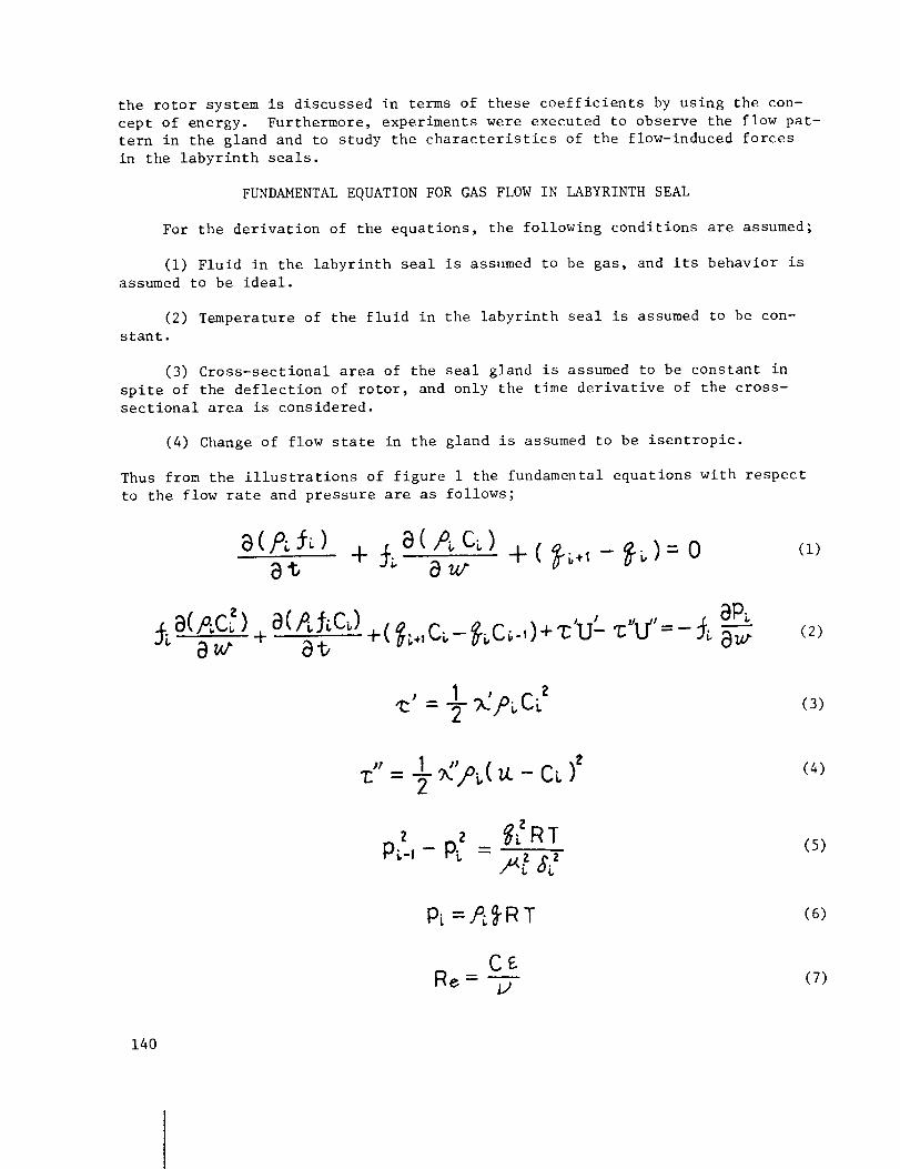
FUNDAMENTALEQUATIONFORGASFLOWIN LABYRINTHSEAL
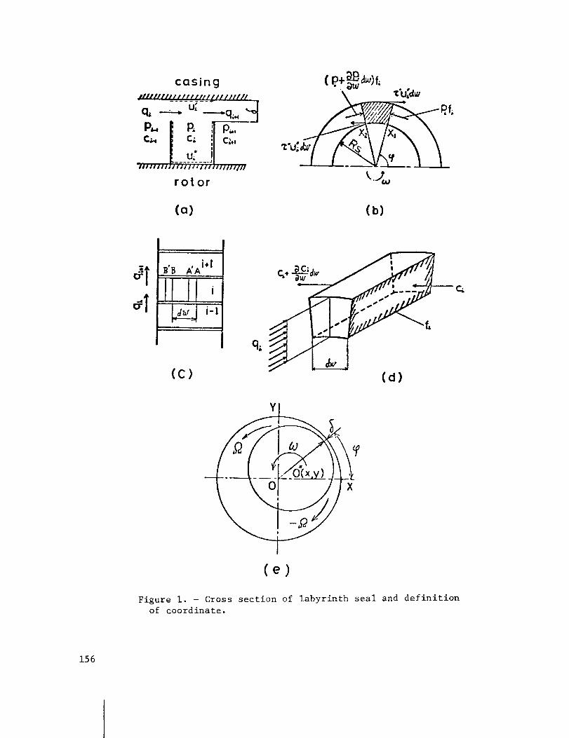
For the derivation of the equations, the following conditions are assumed;
(i) Fluid in the labyrinth seal is assumedto be gas, and its behavior isassumedto be ideal.
(2) Temperature of the fluid in the labyrinth seal is assumedto be con-stant.
(3) Cross-sectional area of the seal gland is assumedto be constant inspite of the deflection of rotor, and only the time derivative of the cross-sectional area is considered.
(4) Changeof flow state in the gland is assumedto be isentropic.
Thus from the illustrations of figure 1 the fundamental equations with respectto the flow rate and pressure are as follows;
a(Ai) + #a(P_ c_)at 8_
+ ( _.,- _)= o (1)
+
8P_8(P_C_) +( _.,c_- _c_-,)+_'u'- _"u"=- #_T_
8_(2)
_' = _-_Cp_CB_ (3)
<'=½ - f
_RTpf-/q 8_
(4)
(5)
PL=,P_'R T (6)
(7)
140

Equations (i) to (7) are nonlinear partial differential equations; so for theanalysis they must be rewritten to linear partial differential equations byusing the perturbation terms from the steady state. Therefore, pressure, axialflow rate, and peripheral velocity in the steady state should be obtained.
ANALYSISOFFLOWIN STEADYSTATE
As the flow in the seal is steady, all state variables are constant; there-fore time derivatives and space derivatives of the state variables are zero.Thus the fundamental equations becomeas follows:
=0
@_,,C_- _C;-, + _'U'- _"V'= 0 (9)
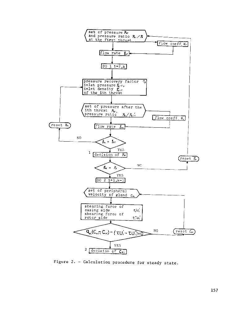
From these equations, state variables in the equilibrium condition are obtained
by using the iterative method as shown in figure 2. For this calculation, the
pressure recovery factor np is
where
A=- (i0)
and H is the angle between the rotating axis and the flow direction passing
through the seal strip.
The steady-state flow rate is given as
_,_= _-_L 2_/E__1 "P (Ii)
LINEARIZATION OF FUNDAMENTAL EQUATION
For the linearization of the fundamental equation, the perturbations of
pressure, peripheral velocity, and flow rate from those of the steady state areintroduced as
P_,= P_(1 +._ _,) (12)
141

(13)
(14)
where P,i, C,i, and q*i are pressure, peripheral velocity, and axial flowrate of steady state in the i th gland and _i, qi, and _i are the nondimen-sional perturbation terms of pressure, peripheral velocity, and axial flow rate.
whereance.
The cross-sectional area in the i th gland is represented as
(15)
hi and 6i are the height of the gland and the radial labyrinth clear-
By denoting the displacement of the center of the rotor (x,y) as
the area of the i th chambersection is obtained as
(16)
(17)
Becausethe change of state in the gland is isentropic change, the followingrelation is obtained:
P_ P_ _-p#
Therefore
8s (18)
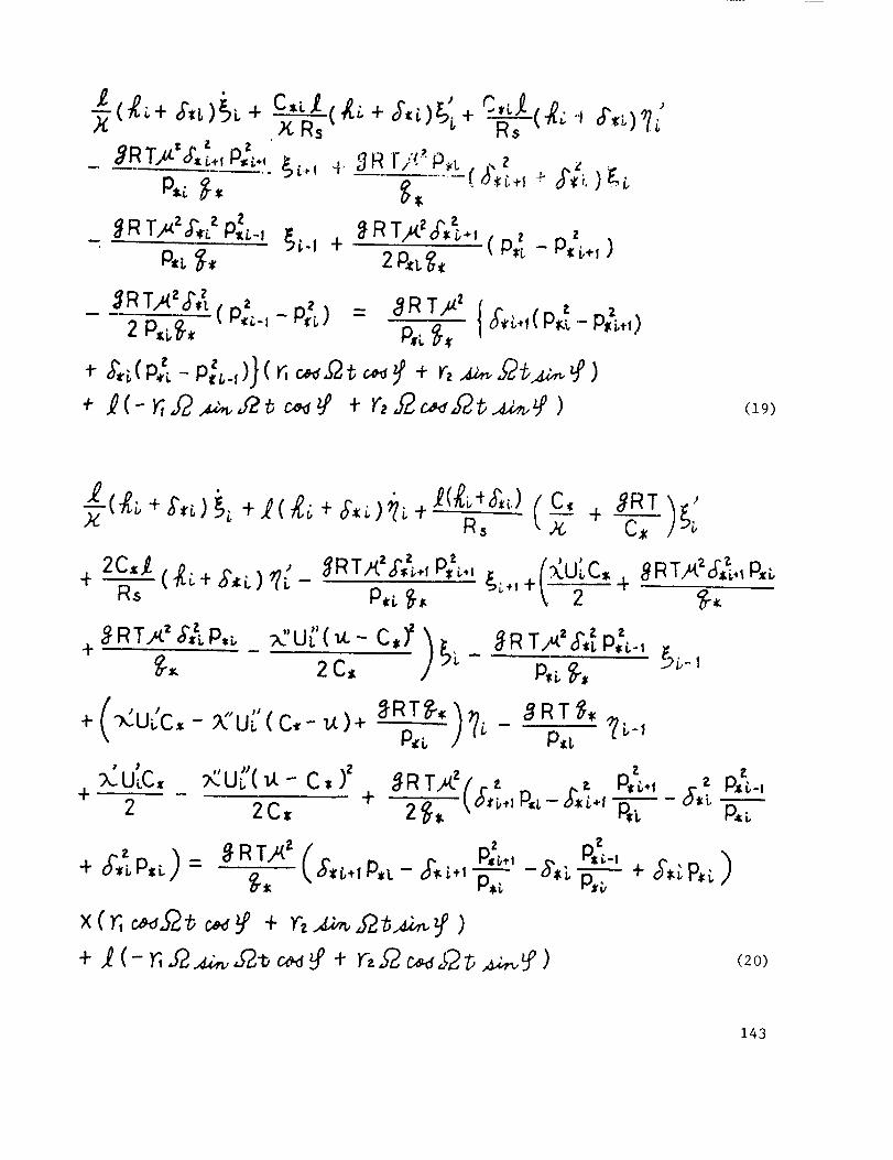
From the above equations, the following linear equations are obtained:
142
_R 2 z z_ T,_ ,;',,:p,__, _-v +P,t, _,
_RTp(.zor',_., p_ p z2P_, ( '[- _*')
,_RT_2_ 2 2
- __ (P;_-,- p;_) = _RT_' {;,,_.,_'m.t- r,;_,,)
(19)
X tR_
2C._ ( _L + ,_,_i.) ¢_ -+ R_
+# RT.'<' #,_LP,_
• )
:;LULC,+
C,_ _RT '
_c'u£'(_.-c,)' '_/2C_,
I
+ ( <u(c, - :_'uL'( c,- u)+
u_ _.- C,
o_RTA<_or_., P_.
_ R TA'_,_ 'P,i,-1
+2 2C,
P_ {.-I
p,_ &_ p,_
(2O)
143
where
• a(.) , a(.)(.):-- (.):-
at ' @_o
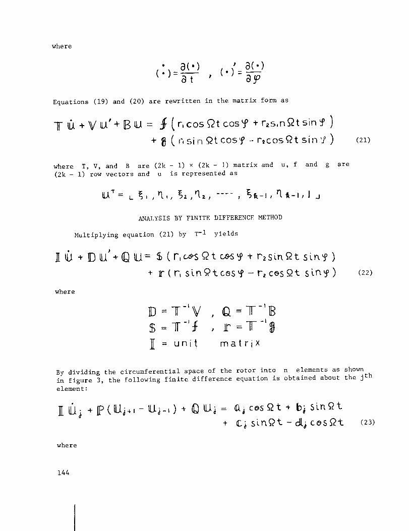
Equations (19) and (20) are rewritten in the matrix form as
]I-6 +VU'+BI3 = ._ (r, cos_t cos_ + r_s,n_tsin_' )
+ _]( r,sin Qt cos_° --r,cosQt sin'Y ) (21)
where T, V, and B are (2k - i) x (2k- i) matrix and u, f and
(2k - i) row vectors and u is represented as
U _= L _,, _l,, _,'l,, .... , _-_, rt_-,, Jj
g are
ANALYSIS BY FINITE DIFFERENCE METHOD
Multiplying equation (21) by T-I yields
]I 6 + D _'+© U = $ (r,_s Qt c_o. r2sinetsin? )
+ Ir(r, slnf#tcssso - r2ces_t sln_o)
where
lm= T-'_ , Q = T-'B$ = T"f , m = T-'_I
= unit matrix
(22)
By dividing the circumferential space of the rotor into n elements as shown
in figure 3, the following finite difference equation is obtained about the jth
element:
Ii 6_ +IPCU_,,-ILL__,) + _)ILt_ = ¢(jc_sQt * bj sLnQt
+ C_ sln_2t - cl[_ cos_t (23)
where
144

P= DI2_ ,
£_ = IF r, cos _,i , d_ : 1["r_ s_n _ ,"l"
U,_ = L U,_t U2j, ..... , uq, .... , u_-l_, ! _jT
0,_ = L o.,i, a_, ..... , aq, ..... , a___, 0 j
_'_= L b,/_, b_, ..... , b_, ..... , b_,-;_, 0 j
1"
When the boundary conditions are set as uj(_j, t) = uj($j + 2_, t), equation(23) is reduced for the overall system to
(24)
where x, a, b, c, d are n(2k- I) row vectors and A is n(2k-l) x n(2k-I)
matrix
The solution of equation (24) is obtained in matrix form as
-- e -/A'_@_. +J0 _
Sot -($,- s)/A+ e
-(_-s)/A I_" -(_-5)_e a o_ _s_ts + e Ib.a_ ,,Q s dsju
Jg -(_>-a)/A,_ f2 s ds - 0 e dl c_ 72 s _s ¢_)
If the rotor is rotating at the steady state, the perturbation terms are equal
to zero; so the initial condition for analysis becomes
-- 0 (26)
By using this condition, equation (25) becomes
% =IE r, _._,.,c2t_+ IFF2._,f2t,, o(-r,.,_..,_Y2_ )+ IH rz,.f2 c,_,.f2b (27)
where
145
_(I+ _2)' b}
=!{_(_ + /A' 1
__{½ _,-,I (If+ ,_z dG = r,,f2
I IA2 )-_I {_ __ (][ +
_2(I + _-:)"/AC}
_(I + ,..Q---_-IAd_I
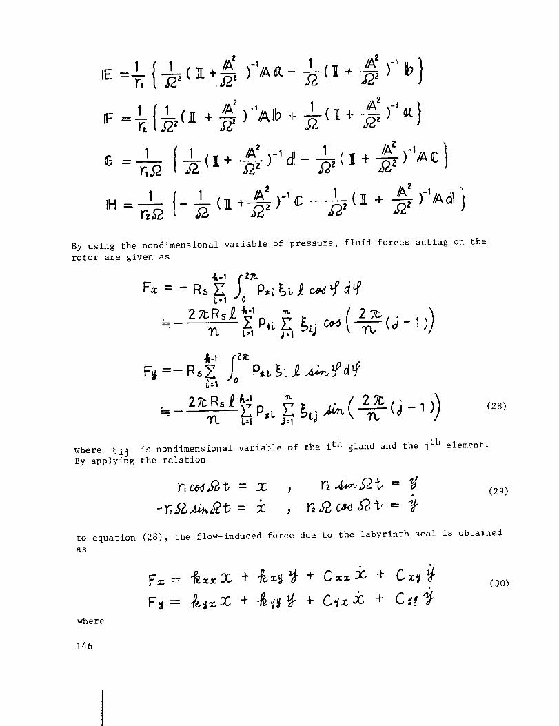
By using the nondimensional variable of pressure, fluid forces acting on the
rotor are given as
&-1 j,'0_/I_
-- )7-P,L E ._j c__ (,_- 1)3% i,,1 ,i -i TL,
F_ =- Rs P,L_,_)-A _ d9p£:_
" < 0--- 27r-"Rs _P'L"Ft.L.-, _ _t,i_'': 27C_(_-1(28)
is nondimensional variable of the ith gland and the jth element.where _ijBy applying the relation
, n,ec ..e =
to equation (28), the flow-induced force due to the labyrinth seal is obtained
as
where
(29)
(30)
146

L-1 J: 1
i,:l J:1
_Rs_ 1 1'2 'ft. '_P,i. _IIH_j
"_,_z 2_Rs,_ _ IE_ --_--(_- i))
2?_Rs_ _-__ P_ _. _j,4_,C 2,,_-
(31)
(32)
(33)
(34)
These coefficients are the spring constants and damping coefficients for the
gas flow through the labyrinth seal when the rotor moves parallel to the cas-
ing axis.
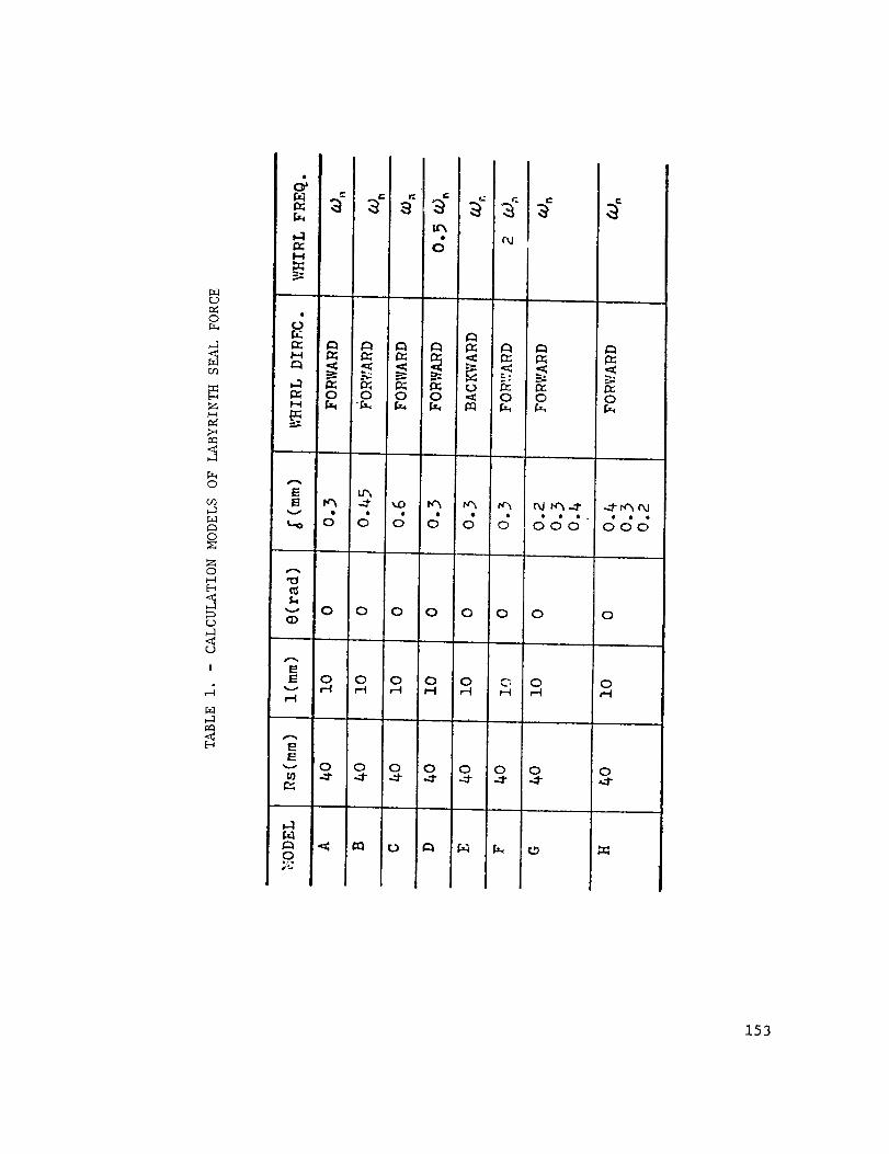
NUMERICAL EXAMPLE
The labyrinth seal having three teeth is used as a numerical model, and
the seal is divided into 24 elements for the finite difference method. Details
of the labyrinth seal, the rotor, and the fluid are shown in tables 1 to 3. In
table i, models A to C investigate the effect of seal clearance, models D to F
investigate the effect of precession, and models G and H investigate the effect
of divergence and convergence seals.
For the calculation, the following values are used:
Flow coefficient = 0.7
X = 64/Re for Re < 1200
= 0.3164Re -0"25 for Re > 1200
147
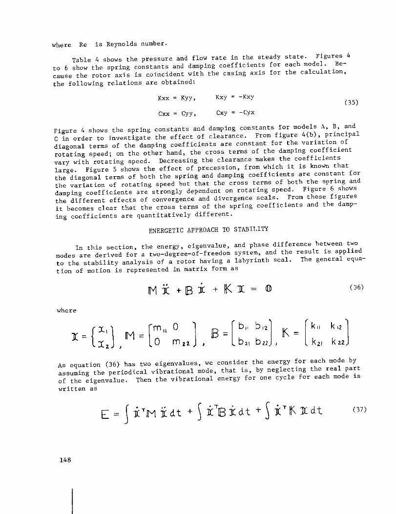
where Re is Reynolds number.
Table 4 shows the pressure and flow rate in the steady state. Figures 4
to 6 show the spring constants and damping coefficients for each model. Be-
cause the rotor axis is coincident with the casing axis for the calculation,
the following relations are obtained:
Kxx = Kyy,
Cxx = Cyy,
Kxy = -Kxy
Cxy = -Cyx
(35)
Figure 4 shows the spring constants and damping constants for models A, B, and
C in order to investigate the effect of clearance. From figure 4(b), principal
diagonal terms of the damping coefficients are constant for the variation of
rotating speed; on the other hand, the cross terms of the damping coefficient
vary with rotating speed. Decreasing the clearance makes the coefficients
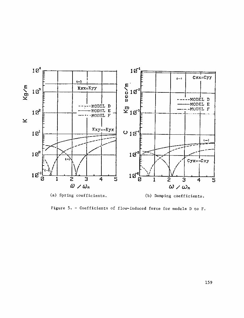
large. Figure 5 shows the effect of precession, from which it is known that
the diagonal terms of both the spring and damping coefficients are constant for
the variation of rotating speed but that the cross terms of both the spring and
damping coefficients are strongly dependent on rotating speed. Figure 6 shows
the different effects of convergence and divergence seals. From these figures
it becomes clear that the cross terms of the spring coefficients and the damp-
ing coefficients are quantitatively different.
ENERGETIC APPROACH TO STABILITY
In this section, the energy, eigenvalue, and phase difference between two
modes are derived for a two-degree-of-freedom system, and the result is applied
to the stability analysis of a rotor having a labyrinth seal. The general equa-
tion of motion is represented in matrix form as
where
,,o B= K=, mz2 , b2, b22 , k2, kz2
As equation (36) has two eigenvalues, we consider the energy for each mode by
assuming the periodical vibrational mode, that is, by neglecting the real part
of the eigenvalue. Then the vibrational energy for one cycle for each mode is
written as
(37)
148
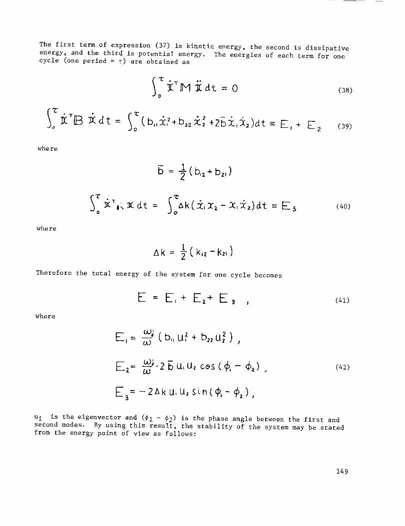
The first term of expression (37) is kinetic energy, the second is dissipative
energy, and the third is potential energy. The energies of each term for one
cycle (one period = T) are obtained as
o
(38)
Io
(b,,_,2,b,2£, 2 +2Bi,i_)_t =- E, + E2 (39)
where
B = _(b,2÷b2,)
Io o
(40)
where
tk -- 2 ( k,, - k,,)
Therefore the total energy of the system for one cycle becomes
where
E = E, + EZ4- E 3 , (41)
F-,-- _uJJ (b,, U,z + b,, U_ )
E2= _. 2 _ _. u, c_s ( #, - ¢,) (42)Ob
_= -2Ak U, U2 sin(#,- _z)
u i is the eigenvector and (#I - _2) is the phase angle between the first and
second modes. By using this result, the stability of the system may be stated
from the energy point of view as follows:
149

(i) If E > 0, the energy of the system is absorbed, and thus the systemis stable.
(2) If E < 0, the energy of the system is dissipative, and thus the sys-tem is unstable.
In expression (42), Ei is the energy obtained by diagonal elements of the
damping coefficient. It is always positive; so if the damping coefficient is
positive, this term always makes the system stable. Also E 2 is the energy
obtained by cross elements of the damping coefficient, and its sign is depen-
dent on the phase angle between _I and _2 o Finally E 3 is the energy ob-
tained by cross elements of (k12 - k21) and the phase angle between _i and _2"
From the above discussion, cross elements of the stiffness and the diagonal
elements of the damping make the system unstable, and the cross elements of the
damping do not affect the stability in this case.
EXPERIMENTS
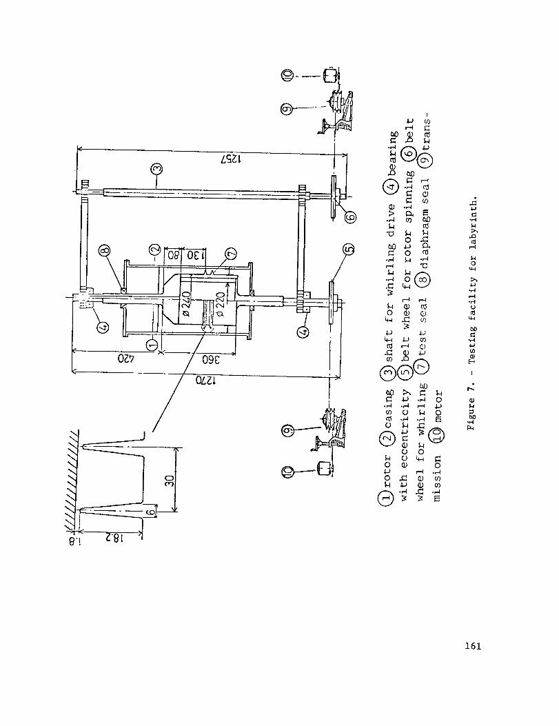
The experimental apparatus shown in figure 7 was used to observe the flow
pattern in the labyrinth seal and to investigate the dynamic behavior of the
labyrinth seal. The rotor is driven by a variable-speed motor system, and its
bearing (with eccentricity) is also driven by another variable-speed motor in
order to obtain an arbitrary whirling speed and spinning speed. A two-stage
labyrinth seal (straight type) is set up at the rotor, whose depth of gland,
pitch, and mean clearance are 18.2, 30.0, and 1.8 millimeters, respectively.
Rotating speed of the rotor and shaft for whirling drive are 84 337 and
93 460 rpm, respectively. The casing is made from polymethyl-meta-acrylate in
order to show the flow state, and water is used for the working fluid.
Pressure in the shroud is measured by the semiconductor pressure gage, and
its signal is analyzed by a real-time analyzer. Figure 8 shows the flow pat-
tern in the shroud, where a continuous vortex in the circumferential direction
occurs in the fluid flow. The form is like a sinusoidal wave which is rotating
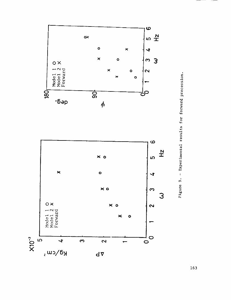
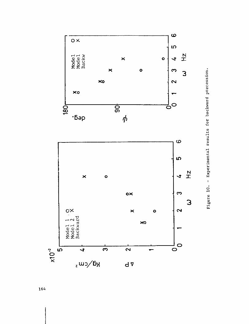
in the same direction as the rotor. Figures 9 and i0 show the dynamic pressure
(perturbation term) of the gland and the phase angle between deflection and the
pressure for forward and backward precession, respectively. From these figures
it is known that the dynamic pressure of the both cases is increased in propor-
tion to the increase of rotating speed but that the tendency of the phase angle
of both cases is the reverse.
MOTION PICTURE SUPPLEMENT
The 8-mm film was taken in order to observe the flow pattern in the gland
of the labyrinth seal, where a continuous vortex in circumferential direction
occurs. The vortex form is like a sinusoidal wave which is rotating in the
same direction as the rotor. Figure Ii shows the two different flow patterns.
The left side shows a conventional mathematical model of the flow pattern in the
gland. This model is usually used to derive the fundamental equation. The real
flow pattern is not similar to the model. In the gland the flow is composed of
vortex and expansion flow as shown by the right side of figure Ii.
150
Thus the next subject we should approach is the mathematical derivation ofthe fundamental equation considering the vortex in the gland.
CONCLUSIONS
The force induced by the labyrinth seal is solved by using the finite dif-ference method, expressed in proportional terms to the velocity and displace-ment of the rotor, and reduced to the expression of oil-film force of journalbearings. Then the effect of the coefficients of the induced force on thestability of the rotor system is discussed from the energy point of view. Theforce induced by the labyrinth seal always makes the rotor system unstable, andthe tendency is remarkable when leakage of the seal is small. The flow patternin the labyrinth seal was investigated experimentally, and it is known that acontinuous vortex in the circumferential direction occurs in the fluid flow.The form is like a sinusoidal wave which is rotating in the samedirection asthe rotor.
EDITORIALSUPPLEMENT
Reproduction of the film frame (fig. 8) was not very successful, so weintroduce figures 12 and 13 in an attempt to demonstrate the film supplement.Figure 12 is a sketch of what appears in the film to be a spiral vortex. Fig-ure 13 represents a possible sequenceof motions of the vortex center resultingfrom the periodic behavior of the flow interface. Onemust also be aware ofthe possible disturbance caused by the air bubbles in the flow field.
These instabilities appear to be linked with those noted in unpublishedwork by Robert C. Hendricks and T. Trent Stetz of the NASALewis ResearchCenter, where a flow visualization study was carried out on a water table todetermine somecharacteristics of flows through sequential Borda-type inlets(no rotation and no centerbody). In figure 14(a) the four lucite Borda modelswere placed in such a way that they touched each other to form a continuouschannel. The inlet water depth was similar to the passage width. The injecteddye revealed that the flow through this configuration continued uninterruptedafter passing the vena-contracta. The models were then placed with spacings of1/3 of the channel passage width (fig. 14(b)). The flow still continued in anuninterrupted mannerafter the vena-contracta. The models were then placedwith spacings of 3/2 of the channel passage (fig. 14(c)). At this separationdistance part of the flow entered the cavities and slight oscillations were ob-served. At a separation distance of 2-1/4 channel passagewidths a very strongoscillation was observed (fig. 14(d)): The exhaust of one passagewould "fan"the flow across the inlet of the subsequent Borda passage. These oscillationsweakenedwhen the separation distance was increased to 4 channel passage widths(fig. 14(e)). A separation of 6 channel widths showedminor oscillations (fig.14(f)). At distances beyond 16 channel widths the flow through each Borda pas-sage appeared nearly independent of the preceding flow (fig. 14(g)).
REFERENCES
(I) Kostyuk, A. G.: A Theoretical Analysis of the Aerodynamic Forces in theLabyrinth Glands of Turbomachines. Teploenergetica, 1972, vol. 19, no. ii,pp. 29-33.
151
(2) Kostyuk, A. G.: Circulation Forces over the Shrouding and Their Influenceon the Threshold Capacity of Large Turbine Unit." Teploenergetica, 1975,vol. 22, no. 3, pp. 41-46.
BIBLIOGRAPHY
Afford, J. S.: Protecting Turbomachinery from Self-Excited Rotor Whirl.Trans. ASME,J. Eng. Power, Oct. 1965, pp. 333-344.
Spurk, J. K. and Keiper, R.: Selbsterregte Schwingungenbei Turbomachineninfolge der LabyrinthstrBmung. Ingenieur-Archiv, vol. 43, 1974, pp. 127-135.
Thomas,H. J.: Zur Laufstabilitgt einfacher Turborotoren, besonders beiSpalterregung. Konstruktion, vol. 30, 1978, H.9, pp. 339-344.
Wright, D. V.: Air Model Tests of Labyrinth Seal Forces on a Whirling Rotor.Trans. ASME,J. Eng. Power, Oct. 1978, pp. 533-543.
152
r_qo
o
Zi--4
5
0
0
Zot-.4[.--t
5rDM
!
0
ddd ddd
0 0
0 0I-I e-I
0 0
E u_
V
CD0 0 0 0 0 0
r-I
0 0 0 0 0 0,-4 ,_ _ _-I _
0 0 0 0 0 0
153

zo o
I-q
[---t
wh
LP_
NI
S
N?
w_
N
S
0o0
• 00 (_I
°I
Et
0000
o
o
zo
o
[---t
o
0 o',
0 e-t
U
tr_. _
o _u% r_I_/ ,-i
C
154

>
I
r._
I
J
• • • • • • • •
",_ -d" C,I _ _ _ _
!_- D'.- C'.- L'_ D,- C_ _ OO
" _j " " _ ' ,4 '..-.. ,--.I _-q r-I ,-N f-(
,_" O O O O O O O O
' 'O "TO _O -ro O O O,-4 _ _ 6"-I _ _ ,--I
o o_ _-_ o O O c_.
o_0
_°
09
o
.o o°
r-t o_v
155
casingJtl/t//I/llltl/l/I/ll/ll///
a_._2Z-_:-Z_q:.,_p,_ I p, :lp.,c_lc, _c:.,
L__:-JI:iiilllllljitlllillllll/illlll
rotor
_.gU/
\ "='u;,_=,
_ ,
(a) (b)
_'B A'Ai*l
(c) (d)
Y
(e)
Figure i. - Cross section of labyrinth seal and definitionof coordinate,
156
set of pressure P,,and pressure ratio _,,/P,at the first throat
_f!ow rate _,,_
IDo_ i--2,k1
1,ressure recovery factor q'l
nlet pressureP_-f,
7inlet density __,
|of the ith throat
1set of pressure after the>Ith throat P,i,pressure ratio P,_/ P,;_,
.1If_owrate_;_I
1 ideclslo n of P'_I
IDO 2 i=l,k-i 1
1set of peripheral
velocity of gland c,,/-
1
I shearing force of
casing side z_'U_'
shearing force ofrotor side T,"U/'
II flow coeff. _I
(reset c',). _.
Figure 2. - Calculation procedure for steady state.
157

--,J-i
-- J+l
Ii,J-I
i,Jl
i,j+l,I
Figure 3. - Definition of mesh points for finite
difference method.
E\
• T VKxx:K_ Y
(-)
. mqlw
-- MODEL A
.... YODEL E
---- MODEL C
10' I: Kxy=-Kyx
" 2-,lifo I 2 3 4 5
\_:xl /// -- :,_O_i;'L A
_X// "- HOD.'-'L C
1_ .[g'. i,l.I,I 2 3 4 5
(a) Spring coefficients. (b) Damping coefficients.
Figure 4. - Coefficients of flow-induced force for models A to C.
158
E\_n
v
! _4
10 _
10'
le"
..... MODEL D--MODEL E
.... MODEL F
IKxy=-gyx
/ ._.- i _
E
o
F
|--)
_\ /- _ I \ • /
l• | | .
1 2 3 4 5 1_0
I
Cxx=Cyy
..... MODEL D
--MODEL E
..... MODEL F
(a) Spring coefficients. (b) Damping coefficients.
Figure 5. - Coefficients of flow-induced force for models D to F.
159

E\
15
10 4
101
10_0
'_%
K_=K_!i -i
JiI
FP
t.... .j.......
-- MODEL G
..... MODEL Hi i ,
Kxy=-Kyx
• i
E
s
£ ! •
2 B 4 5 10-60
. Cxx=lCyy
-" Cxy=-Cyx2-.
. x I'
I;
\I
s'
|
2 "
(a) Spring coefficients.
..... T ......
, I
-- MODEL G
..... MODEL H
f--) ._./
//
• L •
4 5
(b) Damping coefficients.
Figure 6. - Coefficients of flow-induced force for models G and H.
160
o---0I
@- ....._(I
ao
m(D ._l
.,q {o _0
0 ._
0.,A IA "_
4A .C_ {0
_-}
&&eI: w .,-_ 0
o _ 0.,-A .,A I_
0 0
0 _ ¢) co
.,A = .,A
.I-I
-_4
,.D
0
b-,,l.J
-rl
I
,z
161
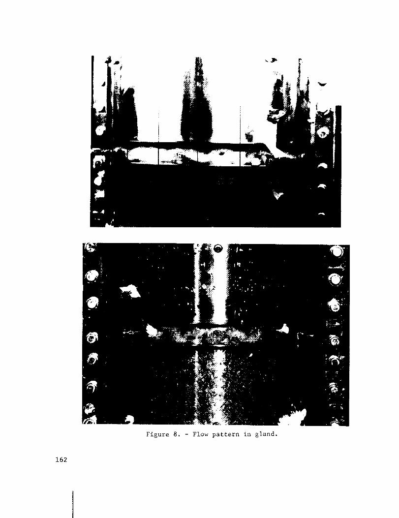
Figure 8. - Flow pattern in gland.
162
i 1.00
X
OX
0cO
OX
,.--_ eq -E_
o
0
X 0
x 0
o
6(3')
X 0
XO
OX
•"o "E:__o oo
X 0
:1( 0
|
"4"| &
(%1
I
d9
I,D
NL_:I:
O o
I,D
O
O
N"I-
3
0.,,-,I
0
0.,
0u_
0u_
I
163
,.f,0
x
0cO
O_
o o_
xo
"6ap
xo
x
x
c_
x o
ox
0_<
oo r_
, I I I
x
clv
u')
o ,,,1"
o o')
O,4
O o
o
_o
I
N"1-
3
_O
tO
oO
3
OO
o-M
n_
,.D
O
4u
-M
I
Ill
°Mr._
164

Conventional mathematical modelReal flow pattern
Figure ii. - Sketch of flow patterns.
RotationFlow
_2
I
Labyrinth
cavity
Figure 12. - Spiral vortex.
165

2 Interface
i
2
Vortexcentermotion
Figure 13. - Possible interface and vortex motionsleading to a "spiral vortex."
166

Flow
(a) Zero separation - jetting.
___--_-_!-..........r-_......__/_JJ , __.__1_. I
-----[ ---1-(b) D/3 Separation- jetting.
(c) 3D/2 Separation - oscillation.
(d) 9D/4 Separation, maximum-amplitude oscillation.
_.....-._.=._"_..-.--__---="-,_I J / ' I
(e) 4D Separation, oscillation.
I != 6D
- I _--I(f) 6D Separation, minor oscillations.
16D _ _
r
(g) 16D Separation, nearly independent of reservoir.
Figure 14. - Flow visualization of four sequential Borda-type inlets.
167


![PRESSURE ACTIVATED LEAF SEAL TECHNOLOGY …sco2symposium.com/papers2014/turbomachinery/22-Grondahl.pdfRegarding gas turbine high pressure packing (HPP) labyrinth seals Johnston [7]](https://static.fdocuments.us/doc/165x107/607c34bf102f8b4dd64a7ecd/pressure-activated-leaf-seal-technology-regarding-gas-turbine-high-pressure-packing.jpg)