Evaluation of High-Angle-of-Attack Handling Qualities … Evaluation of High-Angle-of-Attack...
23
29-l Evaluation of High-Angle-of-Attack Handling Qualities for the X-31A Using Standard Evaluation Maneuvers Patrick C. Stoliker and John T. Boswonh NASA Dtyden Flight Research Center Edwards, CA 93523 U.S.A. 1. ABSTRACT The X-31A aircraft gross-acquisition and tine-tracking handling qualities have been evaluated using standard evalua- tion maneuvers developed by Wright Laboratory, Wright- Patterson Air Force Base. The emphasis of the testing is in the angle-of-attack range between 30” and 70”. Longitudinal gross-acquisition handling qualities results show borderline Level l/Level 2 petfomwnce. Lateral gross-acquisition testing results in Level l/Level 2 ratings below 45’ angle of attack, de- grading into Level 3 as angle of attack increases. The tine- tracking performance in both longitudinal and lateral axes also receives Level 1 ratings near 30” angle of attack, with the rat- ings tending towards Level 3 at angles of attack greater than 50”. These ratings do not match the expectations from the ex- tensive close-in combat testing where the X-31A aircraft dem- onstrated far to good handling quabties maneuvering for high angles of attack. This paper presents the results of the high- angle-of-attack handling quahbes flight testing of the X-31A aircraft. Discussion of the preparation for the maneuvers. the pilot ratmgs, and selected pilot comments are included. Evalu- ation of the results IS made in conjunction with existing Neal- Smith, bandwidth, Smith-Geddes, and military specifications. 2. NOMENCLATURE AOA CHR CIC EFM HARV HUD KIAS LOES MATV MAX AB PI0 PST RPC SSLA STEM angle of attack, deg Cooper-Harper rating close-in combat Enhanced Fighter Maneuverability High Angle of Attack ResearchVehicle head-up display knots indicated air speed lower-order equivalent systems Multi AXIS Thrust Vectoring maximum afterburner pilot-induced oscillation poststall roll perfomnnce classification slow-speed line-abreast standard evaluation manewer 3. INTRODUCTION Controlled flight at high angles of attack (AOAs) provides a modem tighter aircraft with the ability to turn rapidly, provid- ing enhancednose-pointing capability. The ability to accumte- ly point the nose of the aircraft in a timely manner is the basis for handling qualities criteria and ratings. With the exception of recent flight programs such as the F-16 Multi Axis Thrust Vectoring (MATV),’ F-18 Hi h J Angle of Attack Research Vehicle (HARV)? and X-29A. an opportunity for flight test evaluations at poststall (PST) angles of attack has not existed. The Handling Qualities Military Standard (MIL-STD1797)4 provides a summary of criteria for handling qualities that have been derived primarily for a more conventional flight regime. Simulation-based critetias~6 have been developed to specifical- ly address flight in the PST regime. Additional criteria7-g have also been developed to address handling qualities of modem augmentedaircraft. Using the X-31 A linear simulation. analyt- ic evaluatmns of the handling qualities at high AOAs were per- formed to predict the characteristics of this aircraft.” Designed specifically for investigation of flight in the PST regime, the X-31A Enhanced Fighter Maneuverability (EFM) program evaluated the benefits of thrust vectoring in a close-in combat (ClC) environment with emphasis on PST or flight at greater than 30’ AOA. Following the completion of the origi- nal X-31A CIC objectwes, a high-AOA handbng quahties flight test program was perfomwl. Standard evaluation maneuvers” (STEMS) were used to assesslongitudtnal and lateral gross acquisition and tine tracking at high AOAs. Pilot ratings and comments were collected immediately following each maneuver. These data were analyzed and compared with existing handling qualities criteria. The development and preparation for the high-AOA handling quahtles flight testing, a summary of the flight test data. a com- parison of the results with existing handling qualities criteria. and a summary of lessons learned during the flight testing are covered in this paper. 4. AIRCRAFT DESCRIPTION The X-31A airplane (fig. 1) is a single-seat tighter contigura- tion with an empty weight of approximately 12,ooOlbm that uses a single GE-F404-400 engine (General Electric, Lynn, Massachusetts). Fuel capacity is approxtmatel)i 4ooOlbm. Two ancraft were built by Rockwell International (Downey, Cali- fornia) and Daimler-Benz Aerospace (Germany). The wmg planform is a double delta with an inboard leading-edge sweep of 56.6” and an outboard sweep of 45’. Tbe wing area, span, and mean chord are 226.3 ft2, 22.833 A, and 12.35 ft respectively. Four trailing-edge flaps on the wing can be deflected symmetrically for pitch control and differentially for roll control. The leading-edge flap is scheduled to deflect as a function of AOA. The aircraft has an all-moving canard for pitch control and to meet the requirement for aerodynamic recovery from extreme AOAs. Tbe vertical tail contains a md- der for directional control at AOAs less than 40”. Pitch and yaw moments can be generated by the three thrust-vector vanes. The inlet lip is moveable and is deflected as a function of AOA. These control effectors were all integrated into a con- trol system’0~‘2 that provided the capability for good control throughout the AOA range. In the longitudinal axis, the control system uses load factor command to a maximum 30” AOA. In the PST regime, from 30’ to 70” AOA, deflections of the control stick command a Paper presented 01 the AGARD FVP Symposium on “Advances in Flight Testing”. held in Lisbon, Portugal, 23.26 September 1996, and published in CP-593.
Transcript of Evaluation of High-Angle-of-Attack Handling Qualities … Evaluation of High-Angle-of-Attack...

29-l
Evaluation of High-Angle-of-Attack Handling Qualities for the X-31A Using Standard Evaluation Maneuvers
Patrick C. Stoliker and John T. Boswonh NASA Dtyden Flight Research Center
Edwards, CA 93523 U.S.A.
1. ABSTRACT The X-31A aircraft gross-acquisition and tine-tracking handling qualities have been evaluated using standard evalua- tion maneuvers developed by Wright Laboratory, Wright- Patterson Air Force Base. The emphasis of the testing is in the angle-of-attack range between 30” and 70”. Longitudinal gross-acquisition handling qualities results show borderline Level l/Level 2 petfomwnce. Lateral gross-acquisition testing results in Level l/Level 2 ratings below 45’ angle of attack, de- grading into Level 3 as angle of attack increases. The tine- tracking performance in both longitudinal and lateral axes also receives Level 1 ratings near 30” angle of attack, with the rat- ings tending towards Level 3 at angles of attack greater than 50”. These ratings do not match the expectations from the ex- tensive close-in combat testing where the X-31A aircraft dem- onstrated far to good handling quabties maneuvering for high angles of attack. This paper presents the results of the high- angle-of-attack handling quahbes flight testing of the X-31A aircraft. Discussion of the preparation for the maneuvers. the pilot ratmgs, and selected pilot comments are included. Evalu- ation of the results IS made in conjunction with existing Neal- Smith, bandwidth, Smith-Geddes, and military specifications.
2. NOMENCLATURE AOA CHR CIC EFM HARV HUD KIAS LOES MATV MAX AB PI0 PST RPC SSLA STEM
angle of attack, deg Cooper-Harper rating close-in combat Enhanced Fighter Maneuverability High Angle of Attack Research Vehicle head-up display knots indicated air speed lower-order equivalent systems Multi AXIS Thrust Vectoring maximum afterburner pilot-induced oscillation poststall roll perfomnnce classification slow-speed line-abreast standard evaluation manewer
3. INTRODUCTION Controlled flight at high angles of attack (AOAs) provides a modem tighter aircraft with the ability to turn rapidly, provid- ing enhanced nose-pointing capability. The ability to accumte- ly point the nose of the aircraft in a timely manner is the basis for handling qualities criteria and ratings. With the exception of recent flight programs such as the F-16 Multi Axis Thrust Vectoring (MATV),’ F-18 Hi h
J Angle of Attack Research
Vehicle (HARV)? and X-29A. an opportunity for flight test evaluations at poststall (PST) angles of attack has not existed. The Handling Qualities Military Standard (MIL-STD1797)4 provides a summary of criteria for handling qualities that have
been derived primarily for a more conventional flight regime. Simulation-based critetias~6 have been developed to specifical- ly address flight in the PST regime. Additional criteria7-g have also been developed to address handling qualities of modem augmented aircraft. Using the X-31 A linear simulation. analyt- ic evaluatmns of the handling qualities at high AOAs were per- formed to predict the characteristics of this aircraft.”
Designed specifically for investigation of flight in the PST regime, the X-31A Enhanced Fighter Maneuverability (EFM) program evaluated the benefits of thrust vectoring in a close-in combat (ClC) environment with emphasis on PST or flight at greater than 30’ AOA. Following the completion of the origi- nal X-31A CIC objectwes, a high-AOA handbng quahties flight test program was perfomwl. Standard evaluation maneuvers” (STEMS) were used to assess longitudtnal and lateral gross acquisition and tine tracking at high AOAs. Pilot ratings and comments were collected immediately following each maneuver. These data were analyzed and compared with existing handling qualities criteria.
The development and preparation for the high-AOA handling quahtles flight testing, a summary of the flight test data. a com- parison of the results with existing handling qualities criteria. and a summary of lessons learned during the flight testing are covered in this paper.
4. AIRCRAFT DESCRIPTION The X-31A airplane (fig. 1) is a single-seat tighter contigura- tion with an empty weight of approximately 12,ooO lbm that uses a single GE-F404-400 engine (General Electric, Lynn, Massachusetts). Fuel capacity is approxtmatel)i 4ooO lbm. Two ancraft were built by Rockwell International (Downey, Cali- fornia) and Daimler-Benz Aerospace (Germany). The wmg planform is a double delta with an inboard leading-edge sweep of 56.6” and an outboard sweep of 45’. Tbe wing area, span, and mean chord are 226.3 ft2, 22.833 A, and 12.35 ft respectively. Four trailing-edge flaps on the wing can be deflected symmetrically for pitch control and differentially for roll control. The leading-edge flap is scheduled to deflect as a function of AOA. The aircraft has an all-moving canard for pitch control and to meet the requirement for aerodynamic recovery from extreme AOAs. Tbe vertical tail contains a md- der for directional control at AOAs less than 40”. Pitch and yaw moments can be generated by the three thrust-vector vanes. The inlet lip is moveable and is deflected as a function of AOA. These control effectors were all integrated into a con- trol system’0~‘2 that provided the capability for good control throughout the AOA range.
In the longitudinal axis, the control system uses load factor command to a maximum 30” AOA. In the PST regime, from 30’ to 70” AOA, deflections of the control stick command a
Paper presented 01 the AGARD FVP Symposium on “Advances in Flight Testing”. held in Lisbon, Portugal, 23.26 September 1996, and published in CP-593.

specific AOA. Three in. of aft stick commands 30” AOA; and full deflection, or 4.5 in., commands 70” AOA. This character- istic results in a stick sensitivity in AOA command of 33.3 deg/ in of stick deflection. The nominal stick force is 5 Ibflin. The rate of change of AOA command was limited to 25 deg/sec. The longitudinal control system also includes an AOA command limiter that was set by the pilot. The AOA limiter provided the capability for the pilot to set the limit for the AOA command in 5” increments from 30” to 70” AOA.
For the lateral-directional axes. deflection of the control stick commands velocity-vector roll rate. The roll stick deflects 3 in. left and right. The maximum allowable roll rate is 240 deg/sec at a low AOA. In PST, the velocity-vector roll rate is between 30 and 50 deglsec, scheduled as a function of dynamic pressure and AOA. During envelope expansion, the pilots had difficulty using full-lateral stick when using full-aft pitch stick because of interference with their legs. To accommodate this. the lateral-stick deflection-t-roll command gain was changed linearly from 1 to 2 between 30’ and 70° AOA. This change results in full-roll rate command being generated with half- stick deflection at 70’ AOA. The mdder pedals can be used to command sideslip at low AOAs, and their command authority is reduced to 0” at an AOA greater than 40”. The basic opera- tion of the aircraft is designed for “feet-on-the-floor” flying.
The primary source of information for the pilot was the head- up display (HUD) (fig. 2). This display contained a conven- tional pitch ladder and heading display. Altitude and altitude rate were displayed on the upper right, while airspeed and Mach number were shown on the upper left. On the left side of the display were two tapes that showed the AOA and load fac- tor. These data were displayed digitally at the top of the tapes. The current AOA command limit was indicated by an arrow next to the AOA tape The HUD also contained a Z-tnrad fixed pipper, depressed 2’ from the waterline with an inner 20-mrad and outer 40-mmd reticle. Flight test instrumentation allowed in-flight recording of the HUD.
5. AIRCRAFI SIMULATIONS Three simulations were used in the preparation for and analysis of the flight test maneuvers: a six-degrees-of-freedom, nonlin- ear simulatio# that incorporated flight hardware and a tixed- base cockpit mock-up; a batch version of the six-degrees-of- freedom simulation; and linear simulations of the longitudinal and lateral-jirectional axes.
The cockpit for the piloted simulation incorporated the pilot displays and controls. A 5 ft by 6.5 ft flat screen projection provided the pilot a limited view out of the cockpit. The field of view for this screen was approximately 30 deg laterally and 20 deg vertically. One feature of the simulation was the capa- bility to project a target aircraft that could be used for practic- ing the maneuvers. The target aircraft trajectory could be “flown” and recorded to allow for training with a repeatable mmeuver.
The batch version of the simulation was used primarily for the generation of linear state-space models. Using these plant descriptions from the batch simulation, the linear simulation was used to generate transfer fimction$ for use in the handling qualities criteria. These transfer functions could be used direct- ly in the criteria evaluation or in the calculation of lower-order equivalent systems (LOES) parameters. ‘Ibe aerodynamic models for the linear simulation were fourth order. The control
system included sensor models, filters, and high-order actuator models.
6. HANDLING QUALITIES EVALUATION During the X-31A flight testing, an informal handling qualities evaluation was conducted during the CIC testing and formal evaluation using STEMS. The CIC testing was performed to evaluate the effectiveness of PST maneuverability.‘4 From a predetermined set of starting conditions. the X-31A airplane was flown against an adversary aircraft. Both pilots were free to manewer as required to try to establish a tracking situation. In addition to the test pilots assigned to the program, service pilots demonstrated the ability to become quickly familiar with the aircraft and to fly aggressively without any limitations on control stick inputs in the PST flight regime. In all of the CIC engagements, the pilots flew the aircraft aggressively to try to “win” the simulated combat.
CIC testing is used as a comparison with the formal handling qualities testing because of the demonstrated ability of the X-31A pilots to successfully accomplish gross acquisitions and perform fine tracking in a high-gain environment at high AOAs. During CIC evaluation, the X-31A aircraft was gener- ally able to outperform adversary aircraft by using PST maneu- vers. Although no handling qualities ratings were made during these tasks, the general consensus was that the X-31A aircraft had good handling qualities (Level 1 or Level 2) in this flight regime, and no major handling qualities deficiencies were noted. Similar handling qualities were expected from the STEM evaluations. A disadvantage of using CIC to evaluate handling qualities is that the AOA varies considerably and the handling qualities characteristics cannot be sorted out as a function of AOA.
A method for providing consistent techniques for flight-test handling quality evaluation has been addressed by the detini- tion of a set of STEMS.” These manewers can obtain evalua- tions at a constant AOA that can then be compared to analysis. During a limited flight test evaluation, the X-31A aircraft used four evaluation maneuvers: three STEMS. and a maneuver developed from CIC testing. The flight test maneuvers were derived from STEM 10 (High-AOA Longitudinal Gross Acquisition), STEM 3 (High-AOA Lateral Gross Acquisition) and STEM 2 (High-AOA Tracking). The chase airplane for the X-31A aircraft, an F-18 aircraft. was used as the target air- plane. Data were collected using a pilot rating sheet that was compleied immediately following each manewer, postflight interviews. a review of in-flight video recordings made through the HUD, and a comprehensive set of telemetered da- ta. The techniques for performing these maneuvers were devel- oped using experience gained from the F-18 HARV program. In order to emulate the acquisition and tracking tasks that were performed during the CIC investigation using the X-31A air- plane, an additional evaluation manewer was flown. This manewer used slow-speed line-abreast (SSLA) initial condi- tions and resulted in acquisition and tracking tasks at a variety of AOAs. The formal handling qualities testing covered a S-month period and used five different pilots during the perfor- mance of 19 nights.
Flight preparation involved practice in the simulator to estab- lish guidelines for manettveting the test and target aircraft. The initial starting positions, target manewer. and timing were defined so that the gross-acquisition or tine-tracking tasks occurred at a specific AOA. To accurately achieve consistent

initial starting conditions, tw” operational ground radars were required because the X-31A aircraft was not equipped with a radar. During testing, the pilots could achieve consistent spac- ing without the ground radars by comparing the relative target size with the HUD reticle.
Pilot c”mme”ts were recorded on a questionnaire immediately following each maneuver. The completion of the questionnaire required a pilot rating using the Cwper-Harper rating (CHR) system Is (fig. 3) and en evaluation of the confidence class (fig. 4). The confidence class rating was used t” help assess the effectiveness of the maneuvers for rating handling qualities. Changing the initial conditions or additional practices improved the confidence class ratings. Pilot c”mme”ts were solicited regarding difficulty, predictability. aggressiveness effects, and control system effects. Following these comments, a pilot-induced oscillation (PIO) rating (fig. 5) and a second CHR were recorded. For lateral gross acquisitions, a rating using the roll perforn~ance classification (RP@’ (fig. 6) was also solicited. The RPC was developed through simulation studies to address the open-loop “atwe of lateral gross acquisi- tion. The RPC is intended to judge the initial rate and rate ““set and is not based on the ability t” arrest the roll rate. The pilot comments were transcribed using the HUD video recordings that were available for every flight.
Each manewer was also evaluated using the telemetered date. Linear models were calculated for each manewer based on the AOA, airspeed, altitude, and estimated fuel state. The linear models were used to generate the parameters and frequency responses required for the handling qualities criteria.
6.1 Longitudinal Grows Acquisition STEM 10 was used as the basis for the longitudinal gross- acquisition task. The X-3lA airplane started 3ooO ft in trail of the target aircraft. At the initiation of this maneuver, the target aircraft entered a steady turn t” the conditions indicated in Ta- ble 1. After predetermined time delays, the X-31A pilot selected maximum afterburner (MAX AB), rolled the aircraft so that the target aircraft was in the pitch plane, and then aggressively pulled t” caphre the target in the pitch plane within the criteria (fig. 7). The pipper and retitles in the HUD provided a reference for evaluating the gross-acquisition and fine-tracking tasks. The goal of the tasks was not t” drive the pipper t” the target, but t” acquire or track the target within the specified criteria in relation to the pipper. The timings were selected so that the gross acquisition would occur at the desired AOA of either 30’. 45”, or 60”. The AOA limiter wes not used during this testing. Table 1 shows the manewer timing for each flight condition.
6.2 Lateral Gross Acquisition Lateral gross acquisitions were flown “sing STEM 3 as a base- line. For these maneuvers, the target aircraft established a steady turn at specified conditions, and the pilot of the X-31A aircraft maneuvered the aircraft t” the target AOA (30”, 45”, or 60”) at maximum afterburner. Depending on how rapidly the pilot applied aft stick. the aircraft could be at I g or a” elevated load factor at the desired AOA. When the target aircraft was at a prespecified angle away from the ““se of the X-3 IA aircraft, the X-31A aircraft was maneuvered aggressively using only lateral stick t” acquire the target in the roll plane within the cri- teria (fig. 8). Table 2 shows the initial conditions for these maneuvers. To assist the pilot in remaining at the targeted AOA and t” try to constrain the manewer to the lateral axis, the AOA command limiter WBS set to the desired value.
Table 1. Task descriptions for longitudinal gross acquisition.
Fhght M~eUVCX condition timing Manewer description 30” AOA, T=O Target begin manewer: MAX AB, Mach 0.45 constant 20” AOA turn, maintain
200 KIAS. T + 4 set X-3lA advance throttle to MAX AB. T + 4 set X-31A roll in plane with target,
perform rapid pull to 30” AOA. 3O”AOA. T=O Target begin menewer: MAX AB. Mach0.60 c”“stant 20” AOA turn. maintain
200 KIAS. T + 4 set X-31A advance throttle t” MAX AB. T + 5 set X-31A roll in plane with target,
perform rapid pull t” 30” AOA. 45”AOA. T=O Target begin maneuver: MAX AB, Mach 0.50 c”“stant 25” AOA [urn, maintain
170-180KlAS. T + 5 set X-31A advance throttle t” MAX AB T + 7 set X-31A roll in plane with target, per-
form rapid pull to 45” AOA. 6O’AOA, T=O Target begin manewer: MAX AB, Mach 0.50 constant 25’ AOA turn, maintain
170.180 KIAS. T + 5 set X-31A advance throttle t” MAX AB. T + 8 set X-31A roll in plane with target, per-
form rapid pull t” 30” AOA.
Table 2. Task descriptions for lateral gross acquisition.
Angle of Attack Test Condition Test Description
30” 170 KIAS F-18 (target): Roll end pull t” 170 X-31A 15OOft KIAS/ 30” AOA, adjust power/ Echelon and attitude t” maintain conditions.
45”
60”
behind F-18 AOA linut = X-31A: MAX AB, pull t” 30” 30” AOA. When target is 30” off
nose, acquire target laterally. 170 KIAS F-18 (target): Roll and pull t” 170 X-31A 15OOft KIAS/ 30” AOA, adjust power/ Echelon and attitude t” maintain conditions. behlnd F-18 AOA limit = X-31A: MAX AB, pull t” 45” 45” AOA.Wben target is 30”-45”off
nose, acqwe target laterally. 170 KIAS F-18 (target): Roll and pull to 170 X-31A 15oOft KlAS/ 30” AOA, adjust power/ Echelon and attitude t” maintain condrtions. behind F-18 AOA limit = X-31A: MAX AB, pull t” 60” 60” AOA. When target is 30”45”
off ““se, acquire target laterally.

6.3 Fine-Tracking Evahtation 6.4 Combined Maneuvers The tine-tracking evaluation consisted of two phases. Phase 1 testing was performed at AOAs of 10”. 15,” and 20’ to estab- lish a reference point for comparison with other conventional AOA evaluations and testing in the PST regime. During phase 1. fine tracking was performed only in the longitudinal axis. Phase 2 testing, based on STEM 2, evaluated fine tracking at AOAs of 30”, 45.” and 60” for the longitudinal and lateral axes. The AOA command limiter was not used in fine-tracking evaluations.
Initial testing in Phase 2 concentrated on longitudinal tine- tracking evaluations while the manewer setup was refined. Because only one axis was being evaluated at a time, the manewer had to be set up with the target approximately in the reticle so that maneuvering could be pa’fomxd only in the axis being evaluated. After an acceptable set of starting conditions was developed, the same setup was used for the longitudinal and lateral tracking tests at each AOA. The X-31A pilot would practice the manewer to ensure that the setup would result in the desired AOA and then perform the manewer twice. First, a longitudinal tine-tracking task was performed and pilot ratings were given. Then a second manewer was performed where lat- eral tracking and ratings would be done. Table 3 shows the maneu~er sequence and figure 9 shows the criteria. To test the ability to make precise longitudinal changes in track point. the manewer description called for the pilot to move the pipper from nose to tail. Similarly, the lateral tracking task required the movement of the pipper from wing tip to wmg tip.
Pilots consistently commented on the difference between the types of maneuvers used in the handling qualities evaluations and the maneuvering perfomxd during CIC. To address the perceived handling qualities differences between CIC and STEMS, a combined manewer was evaluated during one flight. For this manewer, the starting conditions were those of the SSLA setup from the CIC flight tests. The X-31A and F-18 aircraft started side by side at the same speed and aitifude- 215 knots indicated airspeed (KIAS) and 25,ooO ft-separated by 1500 ft. For the handling qualities evaluation, the maneu- vering began on the call of the X-31A pilot. The aircraft initially Nmed towards each other with the X-31A aircraft going over the target aircraft. Then the F-l 8 aircraft performed a single heading reversal and maintained a steady Nm at 30” AOA and 170 KIAS. The X-31A aircraft maneuvered as required to acquire and track the target. Multiple acquisitions were achieved by lagging off of the target aircraft and then mamtveting aggressively to reacquire the target. Figure 10 shows the rating criteria.
7. HANDLING QUALITIES RESULTS Handling qualities testing was done during 19 flights over a 5-month period in 1994. Five pilots participated in the testing, using both X-31A aircraft. When acquiring the pilot comments at the completion of each manewer, a CHR was solicited before and after the detailed comments. Having the pilot repeat the CHR at the end of the questionnaire allowed a reassessment of the rating in light of the more detailed ccnmnents and
Table 3: Task descriptions for fine tracking.
Angle of Attack
10”
Test Condition
0.80 Mach number X-31A 15OOftbehindF-18
Test Description
F-18 (target): Roll and pull to 3 g, adjust power/attitude to maintain conditions.
15”
X-31A: Roll and pull to 1OOAOA for longitudinal tracking.
(Repeat with target at 1.8 g and initial Mach number of 0.60.)
0.75 Mach number F-18 (target): Roll and pull to 3.5 g, adjust power/attitude N maintain conditions. X-31A 15OOftbehindF-18
15” 0.70 Mach number X-3lA 1500 ft behind F-18
X-3lA: Roll and pull N 1YAOA for longitudinal tracking.
(Repeat with target at 2.1 g and initml Mach number of 0.55.)
F-18 (target): Roll and pull N 4.0 g. adjust power/attitude N maintain conditions.
300
45”
60”
180 KIAS X-31A 15OOftb&indF-18
180 KIAS X-31A 1500 ft behind F-18
180 KIAS X-31A 1500 ft behind F-18
X-3lA: Roll and pull to 20” AOA for longitudinal tracking.
(Repeat with target at 2.4 g and initial Mach number of 0.50.)
F-18 (target): Roll and pull to 180 KlAS/25”AOA, adjust power/attitude to main- tain conditions.
X-31A: MAX AB, at 20” angle off, roll and pull to 3O”AOA for tracking.
F-18 (target): Roll and pull to 160 KlASl30” AOA, adjust power/attitude to maintain conditions.
X-31A: MAX AB, at 30” angle off, roll and pull to 45” AOA for tracking.
F-18 (target): Roll and pull to 170 KIAS/ 30” AOA, adjust power/attitude to maintain conditions.
X-31A: MAX AB, at 45’ angle off, roll and pull N 6O’AOA for tracking.
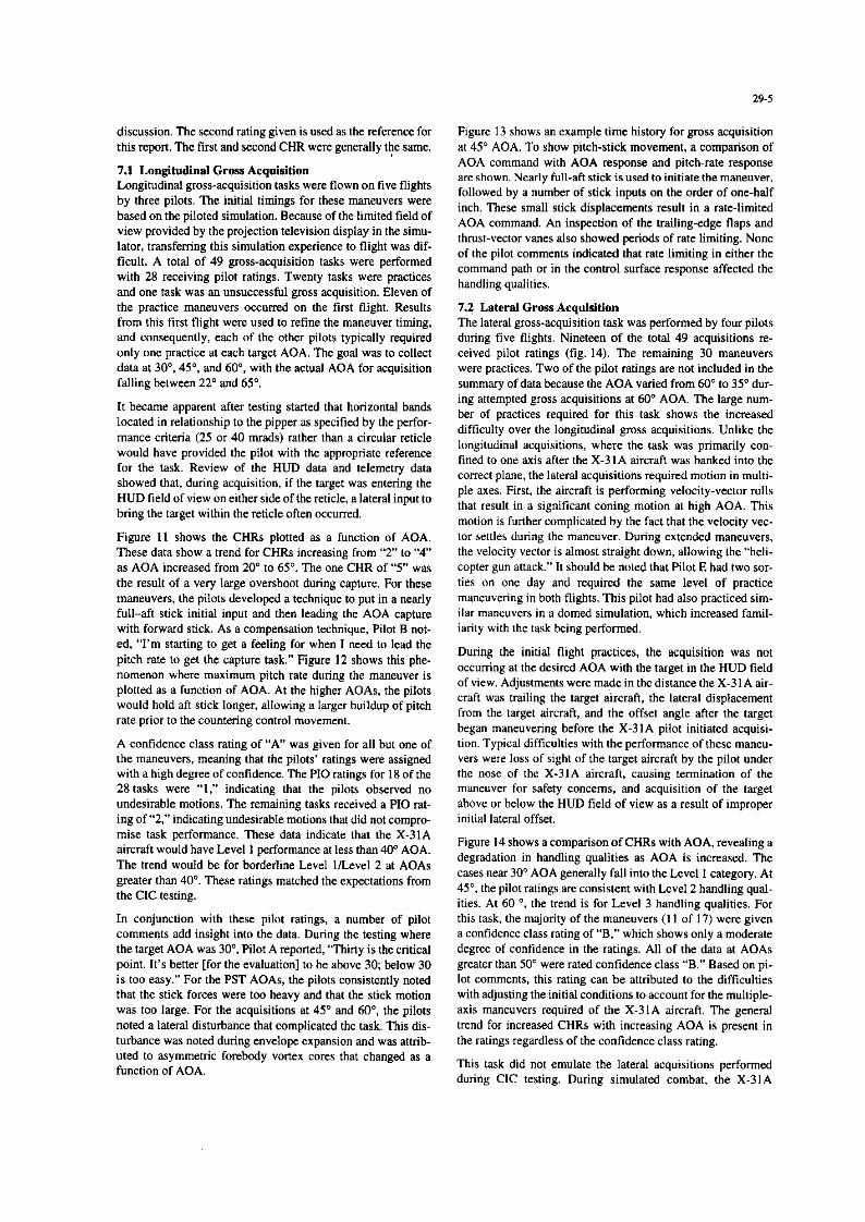
29-5
discussion. The second rating given is used as the reference for this report. The first and second CHR were generally the same.
7.1 Longitudinal Gross Acquisition Longitudinal gross-acquisition tasks were flown on five flights by three pilots. The initial timings for these maneuvers were based on the piloted simulation. Because of the limited field of view provided by the projection television display in the simu- lator, transferring this simulation experience to flight was dif- ficult. A total of 49 gross-acquisition tasks were performed with 28 receiving pilot ratings. Twenty tasks were practices and one task was an unsuccessfol gross acquisition. Eleven of the practice maoeovers occurred on the first flight. Results from this first flight were used to refine the manewer timing, and consequently, each of the other pilots typically required only one practice at each target AOA. The goal was to collect data at 30”. 45”. and 60’, with the actual AOA for acquisition falling between 22” and 65”.
It became apparent after testing started that horizontal bands located in relationship to the pipper as specified by the perfor- mance criteria (25 or 40 mrads) rather than a circular reticle would have provided the pilot with the appropriate reference for the task. Review of the HUD data and telemetry data showed that, during acquisition, if the target was entering the HUD field of view on either side of the reticle, a lateral input to bring the target within the reticle often occurred.
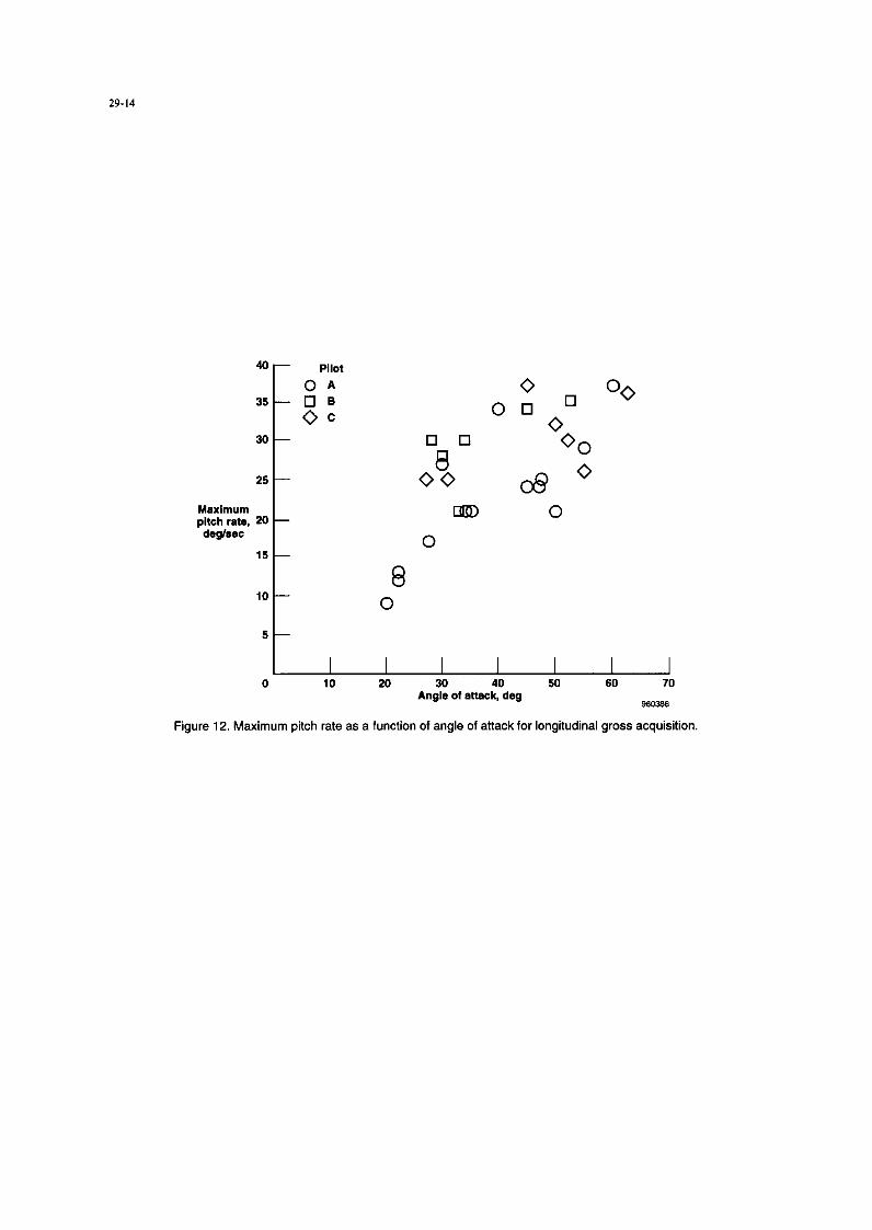
Rgure 11 shows the CHRs plotted as a function of AOA. These data show a trend for CHRs increasing from “2” to “4” as AOA increased from 20” to 65’. The one CHR of “5” was the result of a very large overshoot during capture. For these maneuvers, the pilots developed a technique to put in a nearly full-aft stick initial input and then leading the AOA capture with forward stick. As a compensation technique, Pilot B not- ed, “I’m starting to get a feeling for when I need to lead the pitch rate to get the capture task.” Figure 12 shows this phe- nomenon where maximum pitch rate during the manewer is plotted as a function of AOA. At the higher AOAs, the pilots would hold aft stick longer, allowing a larger buildup of pitch rate prior to the countering control movement.
A confidence class rating of “A” was given for all hut one of the maneuvers, meaning that the pilots’ ratings were assigned with a high degree of confidence. The PI0 ratings for 18 of the 28 tasks were “1,” indicating that the pilots observed no undesirable motions. The remaining tasks received a PI0 rat- ing of “2.” indicating undesirable motions that did not compro- mise task performance. These data indicate that the X-31A aircraft would have Level 1 perfomnoce at less than 40” AOA. The trend would be for borderline Level l/Level 2 at AOAs greater than 40”. These ratings matched the expectations from the CIC testing.
In conjunction with these pilot ratings, a number of pilot comments add insight into the data. During the testing where the target AOA was 30”, Pilot A reported, ‘Thirty is the critical point. It’s better [for the evaluation] to be above 30; below 30 is too easy.” For the PST AOAs, the pilots consistently noted that the stick forces were too heavy and that the stick motion was too large. For the acquisitions at 45” and 60”. the pilots noted a lateral disturbance that complicated the task. This dis- turbance was noted during envelope expansion and was attdb- uted to asymmetric forebody vortex cores that changed as a function of AOA.
Flgure 13 shows an example time history for gross acquisition at 45” AOA. To show pitch-stick movement, a comparison of AOA command with AOA response and pitch-rate response are shown. Nearly full-aft stick is used to initiate the manewer, followed by a number of stick inputs on the order of one-half inch. These small stick displacements result in a rate-limited AOA command. An inspection of the trailing-edge flaps and thrust-vector vanes also showed periods of rate limiting. None of the pilot comments indicated that rate limiting in either the command path or in the control surface response affected the handling qualities.
7.2 Lateral Gross Acquisition The lateral gross-acquisition task was performed by four pilots during five flights. Nineteen of the total 49 acquisitions re- ceived pilot ratings (fig. 14). The remaining 30 maneuvers were practices. Two of the pllot ratings are not included in the summary of data because the AOA varied from 60” to 35” dur- ing attempted gross acquisitions at 60” AOA. The large num- her of practices required for thts task shows the increased difticulty over the longitudinal gross acquisitions. Unlike the longitudinal acquisitions, where the task was primarily con- fined to one axis after the X-31A aircraft was banked into the correct plane, the lateral acquisitions required motion in multi- ple axes. First, the aircraft is performing velocity-vector rolls that result in a significant coning motion at high AOA. This motion is further complicated by the fact that the velocity vec- tor settles during the maneuver. During extended maneuvers, the velocity vector is almost straight down, allowing the “heli- copter gun attack.” It should be noted that Pilot E had two SOT- ties on one day and required the same level of practice maneuvering in both flights. This pilot had also practiced sim- ilar manewers in a domed simulation. which increased famil- iarity with the task being performed.
During the initial flight practices, the acquisition was not occurring at the desired AOA with the target in the HUD field of view. Adjustments were made in the distance the X-3 1 A air- craft was trailing the target aircraft, the lateral displacement from the target aircraft, and the offset angle after the target began maneuvering before the X-31A pilot initiated acquisi- tion. Typical difficulties with the performance of these maneu- vers were loss of sight of the target aircraft by the pdot under the nose of the X-31A aircraft, causing termination of the manewer for safety concerns, and acquisition of the target above or below the HUD field of view as a result of tmproper initial lateral offset.
Figure 14 shows a comparison of CHRs with AOA, revealing a degradation in handling qualities as AOA is increased. The cases near 30” AOA generally fall into the Level 1 category. At 45”. the pilot ratings are consistent with Level 2 handling qual- ities. At 60 ‘, the trend is for Level 3 handling qualities. For this task, the majority of the maneuvers (I 1 of 17) were given a confidence class rating of “B.” which shows only a moderate degree of confidence in the ratings. All of the data at AOAs greater than 50” were rated confidence class “B.” Based on pi- lot comments, this rating can be attributed to the difficulties with adJusting the initial conditions to account for the multiple- axis manewers required of the X-31A aircraft. The general trend for increased CHRs with increasing AOA is present in the ratings regardless of the confidence class rating.
This task did not emulate the lateral acqwsltions performed during CIC testing. During simulated combat, the X-3lA
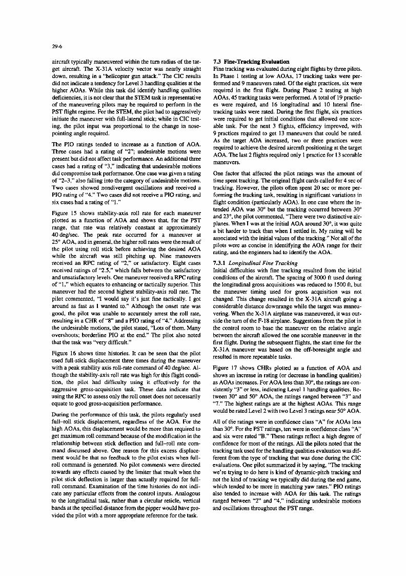
aircraft typically maneuvered within the hrn radius of the tar- get aircraft. The X-31A velocity vector was nearly straight down, resulting in a “helicopter gun attack.” The CIC results did not indicate a tendency for Level 3 handling qualities at the higher AOAs. While this task did identify handling qualities deficiencies, it is not clear that the STEM task is representative of the maneuvering pilots may be required to perform in the PST flight regime. For the STEM, the pilot had to aggressively initiate the manewer with full-lateral stick; while in CIC test- ing, the pilot input was proportional to the change in nose- pointing angle required.
The PI0 ratings tended to increase as a function of AOA. Three cases had a rating of “2”; undesirable motions were present but did not affect task performance. An additional three cases had a rating of “3,” indicating that undesirable motions did compromise task performance. One case was given a rating of “2-3.” also falling into the category of undesirable motions. Two cases showed nondivergent oscillations and received a PI0 rating of “4.” Two cases did not receive a PI0 rating, and six cases had a rating of “1.”
Figure 15 shows stability-axis roll rate for each manewer plotted as a function of AOA and shows that, for the PST range, that rate was relatively constant at approximately 40deg/sec. The peak rate occurred for a maneuver at 25” AOA, and in general, the higher roll rates were the result of the pilot using roll stick before achieving the desired AOA while the aircraft was still pitching up. Nine maneuvers received an RPC rating of “2,” or satisfactory. Eight cases received ratings of “2.5,” which falls between the satisfactory and unsatisfactory levels. One manewer received a RPC rating of “1,” which equates to enhancing or tactically superior. This manewer had the second highest stability-axis roll rate. The pilot commented, “I would say it’s just fine tactically. I got around as fast as I wanted to.” Although the onset rate was gwd, the pilot was unable to accurately arrest the roll rate, resulting in a CHR of “8” and a PI0 rating of “4.” Addressing the undesirable motions, the pilot stated, ‘Lots of them. Many overshoots; borderline PI0 at the end.” The pilot also noted that the task was “very difficult.”
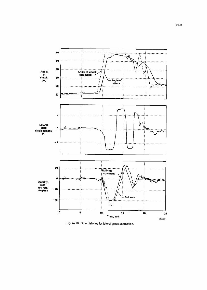
Figure 16 shows time histories. It can be seen that the pilot used full-stick displacement three times during the manewer with a peak stability axis roll-rate command of 40 deg!sec. Al- though the stability-axis roll rate was high for this flight condi- tion, the pilot had difficulty using it effectively for the aggressive gross-acquisition task. These data indicate that using the RPC to assess only the roll onset does not necessarily equate to good gross-acquisition performance.
During the pafonnance of this task, the pilots regularly used full-roll stick displacement, regardless of the AOA. For the high AOAs, this displacement would be more than required to get maximum roll command because of the modification in the relationship between stick deflection and full-roll rate com- mand discussed above. One reason for this excess displace- ment would be that no feedback to the pilot exists when full- roll command is generated. No pilot comments were directed towards any effects caused by the limiter that result when the pilot stick deflection is larger than actuually required for full- roll command. Examination of the time histories do not in& cafe any particular effects from the control inputs. Analogous to the longitudinal task, rather than a circular reticle, vertical bands at the specified distance from the pipper would have pro- vided the pilot with a more appropriate reference for the task.
7.3 Fine-Tracking Evaluation Fine tracking was evaluated during eight flights by three pilots. In Phase 1 testing at low AOAs, 17 tracking tasks were per- formed and 9 maneuvers rated. Of the eight practices, six were required in the first flight. Duling Phase 2 testing at high AOAs, 45 tracking tasks were performed. A total of 19 practic- es were required, and 16 longitudinal and 10 lateral tine- tracking tasks were rated. During the tint flight, six practices were required to get initial conditions that allowed one SCOT- able task. For the next 3 flights, efficiency improved, with 9 practices required to get 13 maneuvers that could be rated. As the target AOA increased, two or three practices were required to achieve the desired aircraft positioning at the target AOA. The last 2 flights required only 1 practice for 13 storable “l~e”“erS.
One factor that affected the pfot ratings was the amount of time spent tracking. The original flight cards called for 4 xc of tracking. However, the pilots often spent 20 set or more per- forming the tracking task, resulting in significant variations in flight condition (particularly AOA). In one case where the in- tended AOA was 30” but the tracking occurred between 30” and 23”. the pilot commented, “There were two distinctive air- planes. When I was at the initial AOA around 30°, it was quite a bit harder to track than when I settled in. My rating will be associated with the initial values of the tracking.” Not all of the pilots were as concise in identifying the AOA range for their rating, and the engineers had to identify the AOA.
7.3.1 Longitudinal Fine Tracking Initial difficulties with tine tracking resulted from the initial conditions of the aircraft. The spacing of 3ooO ft used during the longitudinal gross acquisitions was reduced to 1Y.W ft. but the manewer timing used for gross acquisition was not changed. This change resulted in the X-31A aircraft going a considerable distance downrange while the target was maneu- vering. When the X-31A airplane was maneuvered. it was out- side the hnn of the F-l 8 ah&me. Suggestions from the pilot in the control room to base the maneuver on the relative angle between the aircraft allowed the one scorable manewer in the first flight. During the subsequent flights, the start time for the X-31A manewer was based on the off-baresight angle and resulted in more repeatable tasks.
Figure 17 shows CHRs plotted as a function of AOA and shows an increase in rating (or decrease in handling qualities) as AOAs increases. For AOA less than 30”, the ratings are con- sistently “3” or less, indicating Level 1 handling qualities. Be- tween 30” and 50” AOA, the ratings ranged between “3” and “7.” The highest ratings are at the highest AOAs. This range would be rated Level 2 with two Level 3 ratings near 50” AOA.
All of ttie ratings were in confidence class “A” for AOAs less than 30”. For the PST ratings. ten were in confidence class “A” and six were rated “B.” These ratings reflect a high degree of confidence for most of the ratings. All the pilots noted that the tracking task used for the handling qualities evaluation was dif- ferent from the type of tracking that was done during the CIC evaluations. One pilot summarized it by saying, “The tracking w&e trying to do here is kind of dynamic-pitch tracking and not the kind of tracking we typically did during the end game, which tended to be more in matching yaw rates.” PI0 ratings also tended to increase with AOA for this task. The ratings ranged between “2” and “4,” indicating undesirable motions and oscillations throughout the PST range.

29-I
tolerance bands for the average CHR would be valid for most of the data points with a pilot CHR of “3” or “4.” An alternate relatmnship between average CHR and phase angle at the bandwidth frequency is presented as a dashed line.
The one data point that is anomalous for all three criteria is the 30” AOA tracking case that received a CHR of “6.” The confidence class rating was “A,” indicating a high degree of confidence in the rating. In addition, the PI0 rating of “3” indi- cated that undesirable motions affected the pilot’s ability to perform the task. Ihe pilot did attribute some of the difficulty to aggressiveness, commenting. ‘“The more aggressive you are, the more you oscillate.” Another pilot performing a similar manewer gave a better CHR of “4,” but also commented, “If you are aggressive, you get undesired motions.” Other than pilot technique, one difference noted between the two tasks was that the task that received the degraded rating was performed at a higher airspeed. An analytic investigation of handling qualities” did show a degradation in predicted han- dling qualities during PST flight as airspeed increased with a cmstant AOA.
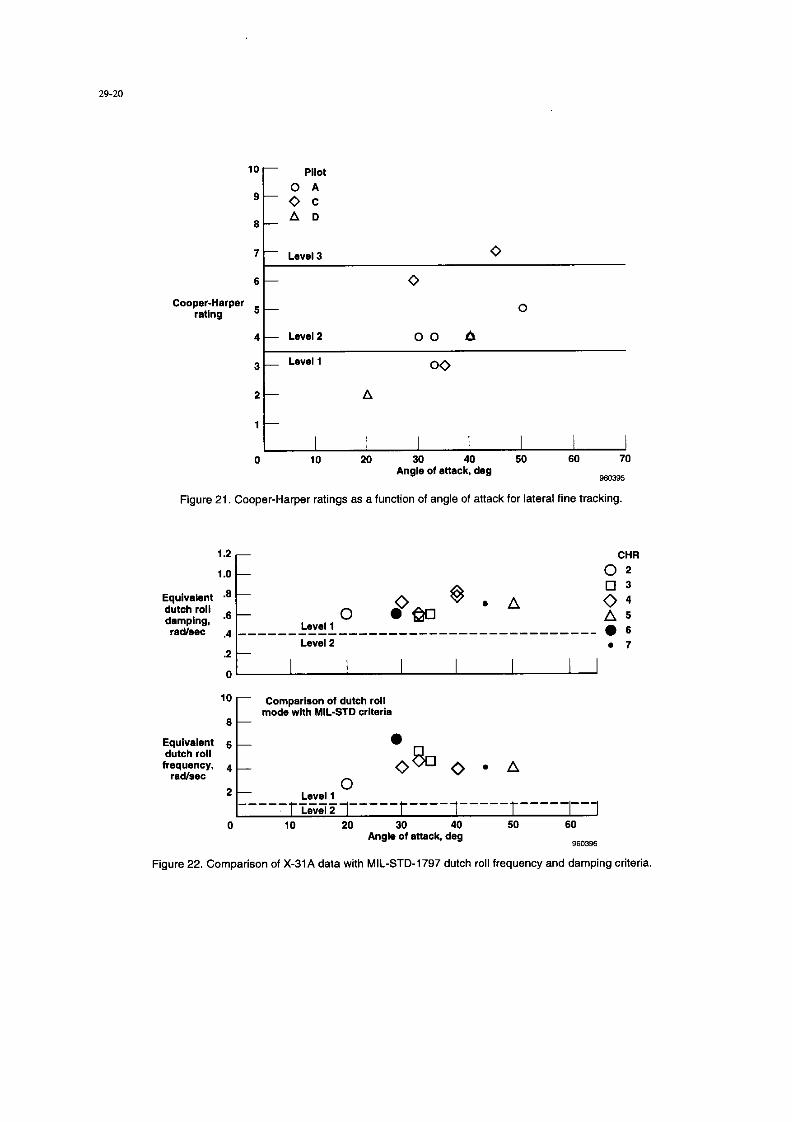
7.3.3 Lnreral Fine-Tracking Figure 21 shows CHRs plotted as a functmn of AOA. As with the longitudinal tracking data, some scatter in the ratings exists near 30” AOA, but the trend is toward higher CHRs as AOA increases. The three data points at an AOA at or greater than 40” had confidence class ratings of “B.” The lower AOA data received a confidence class rating of “A.” The PI0 ratings are consistent with the other tasks in that an increase in undesirable motions as AOA increased existed, with oscillations being reported at the htghest AOAs.
A consistent pilot comment was. ‘“The more aggressive you are. the harder the time you have tracking.” As well as the impact of aggressiveness on the task performance, the pilots also commented that the task frequently required diagonal stick inputs as opposed to pure lateral stick motions. Lateral tracking initially required wing tipto-wing ttp tracking. The tracking task was redefined to use only lateral s&k mputs, but the pilots continued to use diagonal inputs.
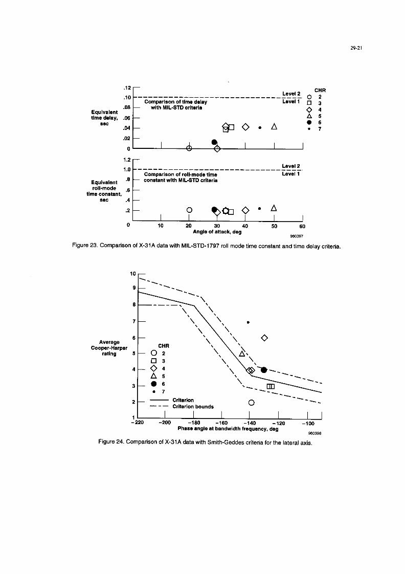
7.3.4 Lateral Fine-Tracking Handling Qualirres Crireria Using LOES derived from the linear models, dutch roll frequency. dutch roll damping, the roll-mode time constant. and the equivalent time delay were calculated and compared with the criteria from MIL-STD-1797 (fig. 22 and 23). These criteria predict Level I handling qualities throughout the AOA range, whtch IS not consistent with the handling qualities rat- ings. These data indicate that dutch roll frequency and damp- ing and the roll-mode time constant are not the factors affectmg high-AOA handling qualities.
The lateral fine-trackin f
ratings were also compared with the Smith-Geddes criterion (fig. 24). Although a limited amount of data extsts, there appears to be general agreement with this criterion.
Some caution must be used when applying the results of linear analysis to the lateral-directional high-AOA tracking tasks. Several nonlinear effects arc evident in the data. The flight condition changes rapidly during the task from a high-speed, high-AOA condition to a low-speed, reduced-AOA condition. The maximum roll-rate command is scheduled as a function of airspeed so that the pilot experiences a reduced command authority as the airspeed decreases. ‘l%e rate limit for the stabibtv-axis roll-rate command was reached several times
The initial instructions for the fine-tracking tasks called for nose-to-tail tracking. Because of the unique geometries that could result during the high-AOA maneuvering, the tracking tasks required both lateral and longitudinal stick inputs to per- form the nose-to-tail tracking because the maneuver plane of the X-31A airplane would not correspond with the plane of symmetry of the target aircraft. This instruction was modified to state that tracking was not necessarily from tmse to tall, but should use only pitch stick inputs and use the appropriate air- craft features as a reference. Even with the modified instruc- tions, the pilots would often use diagonal stick inputs during the tracking tasks.
7.3.2 Longitudinal Fine-Tracking Handling Qualifies Criteria
The X-31A data were evaluated using the Neal-Smith, band- width, and Smith-Geddes criteria to assess the applicability at high AOAs. These criteria are all based on the pitch stick-t+ pitch attitude transfer function. An analytic study” had shown that other criteria based on LOES were not applicable m high- AOA flight. Transfer functions were generated using the linear models based on the mass properties and flight conditions (Mach number, altitude, and AOA) associated with the pilot ratings. The transfer functions were used in the criterion assessment and correlated with the pilot ratings. With the exception of a few data points, the linear analysis results come- late with handling qualities ratings obtained in flight. The low- AOA data and the data with CHRs of “3” tend to fall into the Level I regions for all of the criteria. The data with the higher CHRs seem to fall in clusters, and for all the criteria, these clusters move away from the Level I regions.
Figure 18 shows X-3lA data plotted using the Neal-Smith criterion.’ The Neal-Smith criterion uses a simple compensator model to close the loop of the pitch stick-t-pitch attitude transfer function. The magnitude of the resonant peak in the resulting closed-loop transfer function is compared with the phase angle of the compensation. The high-AOA data indicate that less lead compensation can be allowed. With two excep tions, data with Level I ratings reqmred less than 15’ of lead compensation. A cluster of data near 40” of lead compensation with adjacent CHRs of “5” and “7” exists that may indicate the proximity of the Level 3 boundary. Figure 14 shows the exist- ing boundaries as solid lines, and boundaries indicated by the X-31A PST data are shown as dashed lines. Additional data are required to determine if these boundaries are v&d.
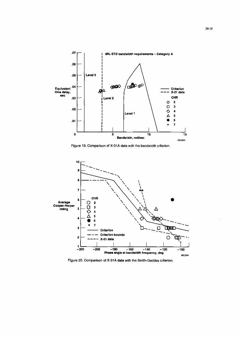
For the bandwidth criterion9 (fig. l9), all of the data show an estimated equivalent time delay of approximately 0.04 sec. This criterion has correlated handling qualities with the esti- mated equivalent time delay and bandwidth frequency calcu- lated from the pitch stick-twpitch attitude transfer function. A reduction in bandwidth exists that is consistent with an increase in AOA and CHR. The X-31A data indicate that the Level I boundaries are reasonable. Several data points exist with a bandwidth of approximately 3 rad/sec that have CHRs of “5” and “7.” indicating that it might be appropriate to move the Level 3 boundary to this bandwidth as shown by the dashed line.
When compared with the Smith-Geddes criterion’ (fig. 20). the X-31A data indicate that the slopes of average CHR as a function of phase angle at the bandwidth frequency need to be steepened. The criterion calculates the bandwidth frequency based cm the slope of the gain relationship from the pitch attttude-t-pitch stick transfer function. In general, the

29-8
during the tine-tracking tasks. The high workload demand on the thrust-vectoring system resulted in rate limiting of the thrust-vector paddles. Also, at high AOAs, moving the pipper from wing tip to wing tip required a combined lateral and longitudinal stick input.
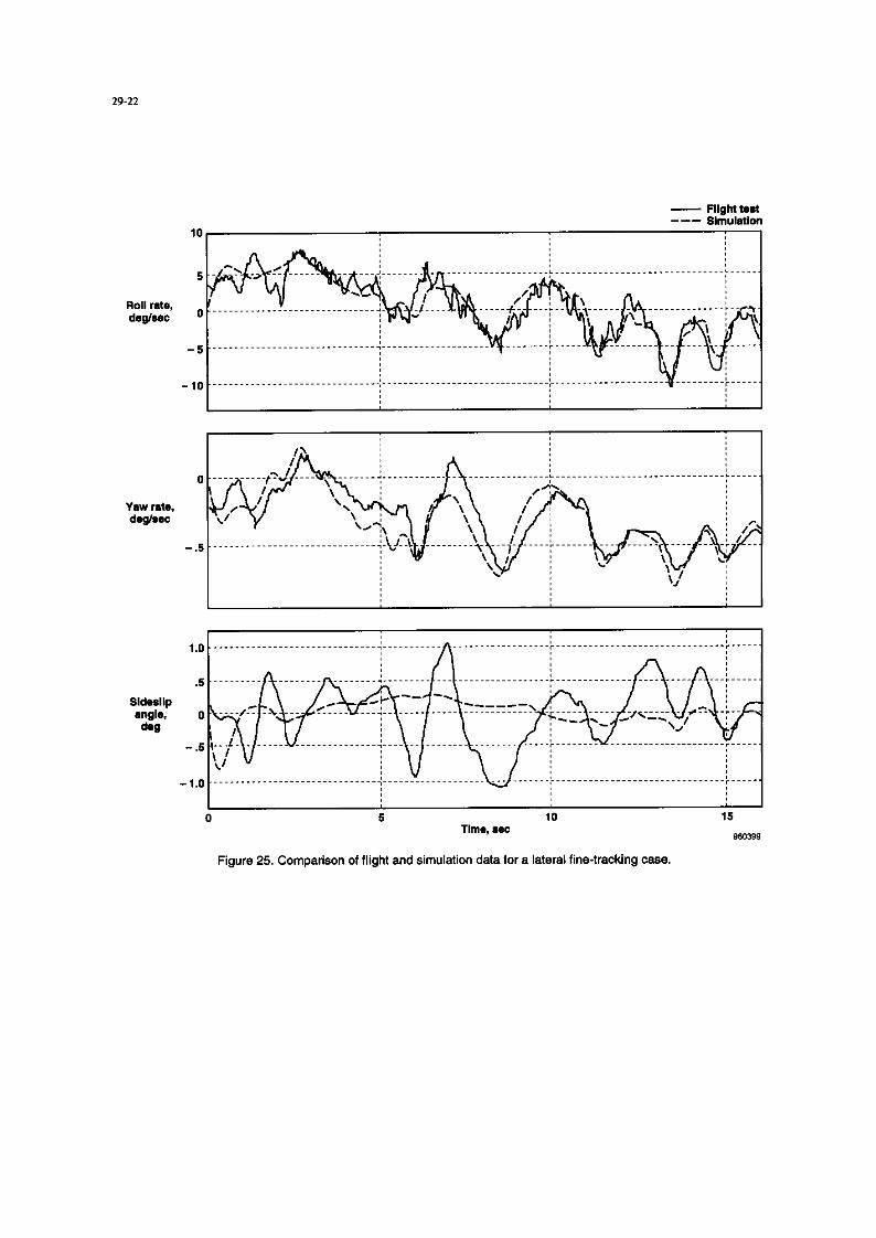
Even a full six-degrees-of-freedom nonlinear simulation did not entirely reproduce the dynamics observed during some of the lateral fine-tracking tasks. Figure 25 shows some of the ex- cursions in yaw rate and sideslip angle that were not duplicated with the nonlinear simulation. These excursions approximately correlate with target overshoots where the target wanders out- side the 20.mrad reticle and may be related to asymmetric fore- body vortex cores. To accurately predict handling qualities requires an analytic model that includes all of the dynamics, so the effect of these vortices should be included.
1.4 Combined Maneuvers The combined manewer was flown four times during one flight by one pilot. Two of the maneuvers were used for prac- tice. Comments and CHR ratings of “3” and “4” were given on the other two maneuvers. No distinction existed in the ratings for lateral or longitudinal tasks, hut fine tracking and gross acquisition were rated separately. In summary, the ratings were given with high confidence and were borderline Level l/ Level 2 for both tracking and acquisition. No undesirable motions were present during the gross acquisition, and the motions did not affect the task during tine tracking. Following the flight, the pilot reported, “The SSLA setup was an excellent starting condition to evaluate handling qualities in the PST regime.”
Figure 26 shows time history data from the second rated manewer, which spanned 60 sec. The AOA ranged between 30” and 70”. Pitch-stick sensitivity can be seen in the AOA command where 15” excursions in the command at the AOA command rate limit of 25 deg/sec can be seen. Full-roll stick was used early in the manewer, and approximately 66 percent of the stick deflection was used in a later acquisition. Peak velocity-vector roll rates of nearly 40 deglsec were observed. The fourth trace shows the timing for the three gross acquisi- tions performed and the periods of tracking. This maneover was initiated at an altitude of 25,ooO A and was completed at an altitude of 14,ooO ft.
As with the other tasks, the pilot commented that the stick forces were “to+ heavy” and the motions were ‘too large.” Be- cause this manewer intentionally used diagonal stick inputs, the pilot was able to comment on stick harmony, ‘The stick movement is much too high; and you have the nonharmony between the pitch stick, which is so sensitive, and the roll stick, which is not so sensitive.”
Because the pilot ratings cover manewers that span a large flight envelope and encompass two axes of control. comparing them with analytic results is difficult. The pilot liked this manewer better and felt it was more representative of the type of flying done during the CIC investigation. The manewer also resulted in the Level l/Level 2 ratings that were expected. Additional testing is required. but this type of manewer may provide a better means of evaluating the PST handling quali- ties, but like CIC, it is of limited value for analysis or design because of the varying flight conditions.
8. LESSONS LEARNED FOR IIIGII-ANGLE-OF- ATTACK HANDLING QUALITIKS TESTING
When flying a new task, backup cards should be prepared for an established task in the event the first task is not working out. During the first PST fine-tracking flight, it was quickly appar- ent to the pilots in the airplane and on the ground that the test as designed would not result in an acceptable tine-tracking task. Almost an entire flight was used to get one data point. Testing of alternate flight cards would have collected additional data, and ground review would have adjusted the test sehtp for the acquisition of PST tine-tracking data.
Some of the pilots thought a domed simulation would have helped them better prepare for the tasks. But it is interesting to note that during the lateral gross acquisitions, the one pilot who had performed the maneovers in a domed simulation required the same amount of in-flight practice as the other pilots.
Care should he taken in task definition. For the tine-tracking tasks, the pilots were asked to do separate longitudinal and lat- eral tracking tasks. Even with instmctions that the inputs should be limited to pitch or roll inputs, the pilots continued to use diagonal stick motions to perform the more classical track- ing tasks of nose-to-tail and wing tip-tc-wing tip. The task definition should also include a reasonable time limit for the performance of the task. One of the reasons 4 set was initially chosen was to try to minimize variation in flight condition dur- ing the performance of the task. This time limit was not enforced during the testing and resulted in a tracking task that lasted 2&30 set with large AOA variations.
Modifications to the HUD could have provided the pilots with the proper cues for the tasks. For longitudinal gross acquiw tion, horizontal bars at 25 and 4.0 mrads would have provided the proper reference for the task that was being rated. Similar- ly, vertical bars could have been used for lateral gross acquisi- tion in place of the circular retitles. This display might reduce the tendency of the pilot to try to place the pipper on the target.
9. CONCLUSIONS The Standard Evaluation Maneuvers (STEMS) provided repeatable tasks that could be compared with analytic linear and nonlinear simulation results. With suitable initial condi- tions and practice, gross acquisition and tine tracking could be performed at the desired angle of attack (AOA). Pilot com- ments indicated that these maneuvers were not consistent with the types of maneuvering performed during the close-in combat (CIC) evaluations. This testing identified problems that may not be significant in actual tasks. Further testing is needed to resolve these differences.
The pilot-assigned ratings for gross acquisition and tine tracking for both the longitudinal and lateral axes were depen- dent on AOA. More undesirable motions and then oscillations existed as AOA increased.
The longitudinal gross-acquisition task was well-defined and provided an easily repeatable task. The pilot ratings and com- ments indicated a high degree of confidence. These ratings reflected the expectations from CIC testing with the aircraft having Level 1 or Level 2 handling qualities.
The lateral gross-acquisition task was one of the most difficult. The task required a significant amount of flight time to adjust the starting conditions to achieve the desired AOA with the

target aircraft in the head-up display field of view for the X-3lA airplane. ‘Ihe pilot proficiency for this task did not improve as significantly as it did for the other acquisition and tracking tasks. The pilot comments and ratings indicated a deg- radation in handling qualities as AOA increased, with Level 3 handling qualities at an AOA near 60”. The ptlot comments noted that this type of acquisition was not similar to the acqui- sittons performed during CIC testing. The degradation in handling qualities was not expected from the CIC testing where the general assessment would have been Level liJaevel2 handling qualibes.
For the longitudinal fine-tracking task, consistent trends existed in regard to the Neai-Smith, bandwidth, and Smith- Geddes criteria. The maneuvers that received Level 1 ratings in flight were rated Level 1 by the criteria. The Levels 2 and 3 data from flight tended to produce consistent results when compared with the linear models and indicated potential mcdi- tications for the criteria. The X-31A handling qualities ratings showed a degradation with AOA that was not observed during the CIC testing.
Lateral tine tracking showed a degradation to Level 3 handling qualities as AOA increased. The X-31A program provided only a limited amount of data that could be compared with the existing criteria. The data showed good general agreement with the Smith-Guides criterion. These data did not provide sufficient information to offer modifications to the existing cri- teria that predicted Level 1 or borderline Level liLevel2.
For both lateral and longitudinal tine tracking, the effect of the velocity-vector settling during the manewer had a significant impact. Future use of this STEM may require modifications to allow a more stabilized starting condition for the fine-tracking tasks. During the X-31A testing, fully separating the lateral and longitudinal tasks was not possible. The pilots generally used diagonal stick inputs regardless of the axes being evaluated.
For control stick harmony, the majority of the comments were noted during the fine-tracking tasks. In these cases, the pilots were using diagonal stick inputs to perform the wing tipto- wing tip and nose-to-tail tracking. The one other task that elic- ited a comment on control stick harmony was the combined manewer. The pilot commented on the disparity in motion for longitudinal and lateral stick displacements (large for roll and small for pitch). Although the control implementation resulted in a limiter for large roll-stick deflection. no particular com- ments were given by the pilots.
The limited testing with the combined manewer was commented upon favorably by the pilots, but these ratings are not amenable to comparison with analytic results because of the rapidly varying flight conditions. This type of manewer may be useful for providing an overall evaluation of aircraft perfomumce in the post-stall flight regime and should be considered as an additional STEM. Like the CIC results, these data are of limited value for analysis because of the varying flight conditions.
10. REFERENCES ‘Sweeney, Joseph E. and Gerzanics, Michael A., “F-16 MATV Envelope Expawm: Testing For Controllable High AOA Manewwing.” Society of Experimental Tesr Pilors Thirty- Eighth Symposium Proceedings, Sept. 1994, pp. 285-295.
ZWichman. Keith D.. “High Alpha Handling Qualities Flight Research on the NASA F/A-18 High Alpha Research Vehi- cle,” High-Angle-of-Attack Technology Conference. NASA Langley Research Cater. Virginia, Sept. 17-19, 1996.
3Webster. Fredrick R. and Putifoy, Dana. X-29 High Angle-of-
Attack Flying Qualities, AF-FI’C-T&91-15. Jul. 1991.
%J.S Department of Defense. Flying Quliries ofPiloted Vehi- cles, MIL-STD-1797. Mar. 1987.
5Krekeler, Gregory C.. Jr.. Wilson, Davtd J., and Riley, David R., “High Angle of Attack Flying Qualities Criteria,” AIAA- 90-0213, Aug. 1990.
6Wilson, David J., Riley, David R.. and Citurs, Kevm D., Fly- ing Qualities Criteria for 60” Angle of Attack, NASA CR4535, vol. I, Dec. 1993.
‘Neal, T. Peter and Smith, Rogers E., An In-flight Investigation
to Develop Control System Design Crireria for Fighter Air- planes. AFFDL-TR-70-74. vol. I, Dec. 1970.
‘Smith, Ralph H., “The Smith-Geddes Criteria,” SAE
Aerospace, Control & Guidance Symposium Reno, Nevada, Mar. 1993.
9Hoh. Roger H., Mitchell, David G., and Hcdgkinson. John, “Bandwidth -A Criterion for Highly Augmented Airplanes,” AGARD CP-333, Jun. 1982, pp. 9-1-9-l I.
‘OStoliker, PC., Simularion Prediction of High-Angle-of-
Attack Handling Qualiries for the X-31A, NASA Th-4758, 1996.
“Cord, Thomas J.. Leggett, David B., Wilson. David J., Riley, David R., and Cihtrs. Kevin D., “Flying Qualities Evaluation Maneuvers,” AGARD CP-548, Mar. 1994, pp. 18-l-18-8.
“Beh, H. and Hofinger, G., “X-3lA Control Law Design,” AGARD CP-548, Mar. 1994, pp. 13-l-13-9.
“Norlin, Ken A., Flight Simulation Software at NASA Dryden
Flight Research Cenrer, NASA TM-104315, Oct. 1995.
“Eubanks, D., Gtitter. R., and Lee, B., “X-31 CIC Flight Test Results,” Four Power SeniorNation Represenrarive Full Enve- lope Agility Workshop, Eglin AFB. Florida. Mar. 1995.
“Cooper, George E. and Harper, Robert P.. Jr., The Use of Pilot Raring in the Evalumion of Aircraff Handling Qualities,
NASA TND5153. Apr. 1969.
‘6Foster, John V., Ross, Holly M., and Ashley, Patrick A., “Investigation of High-Alpha Lateral-Directional Control Power Requirements for High-Performance Aircraft,” AIAA- 93.3647, Aug. 1993.

Mach number- AIrspeed \ o.56
1 Aircrafl g
Angle-of- Angle-of- 4- 4- attack limit attack limit
-l- -2-
a B
Figure 1. X-31A airplane in poststall flight.
7 Rata of
350 -12w cllmbldescent
I 0 I
Heading <&/ Side*‘ip a”g’e
- Altitude
/ ZO-mrad inner retbla
/ Figure 2. Head-up display symbolcgy.

29-11
Adequacy for selected task or required operation’
AIrWEft Demands on the pilot In ~Mcted Pilot characteristics task or requlmd operation’ ratng
EXWll*ti Plkn compenMtlon not a tactor Highly deslrsble for deelred performance
Pilot compenutlon not a factor Negligible deflclencier for deWed ~wf.xmance
FM- some mildly Minimal pilot compensation unplaaunt deficiencies required for desired performance
satisfactory wkhout Moderately objectionable Adsquats performance requires
Very objectionable but Adequate pwformwtce requlre~~ tolenbls deflclencies exiwIsiw pilot compnsation
Adaquote perfoormanw not attaInable wkh maximum tolerable pilot compenwtlon. Controllabllky
Considerable pllot com~nsatlon
phase and/or subphases wkh accompanying conditions.
Classification
A
B
T C
Figure 3. Cooper-Harper rating scale.
Descrlptlon
The pilot rating was asalgned with a high degrea of confidence.
The pilot rating was assIgned with only a moderate dograe of confidence bac.suse of uncertaIntIe Introduced by moderate differences In envIronmental condltlone, or In alrcraft conflguratlon or state, or in task, from what was de&ad.
The pilot rating was assigned with minimum contldwwa baause of Important difference8 between the desired and actual environmental conditions, alrcraft contlguratlon or state, or task, requiring considerable pilot extrapolation.
Figure 4. Classification of pilot confidence factor.
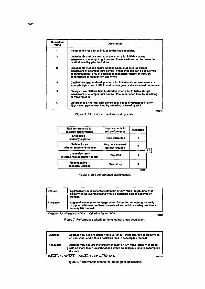
Numdzal rathlg Descrlptlon
1 No tendency for pilot to lnducs undesirsble motions.
2 Unde~irabla motlons tend to occur when pilot inltlate~ abrupt mamuvers or Mtempts tlght control. Those motiona can be prevented or ellmlnated by pllot technique.
3 Undwlrable motlone easily Induced when pilot Inltlatas abrupt rnaneuvws or attempts tlght control. Theae motlonl can be prevented or eliminated but only at wxlflce to task performance or through considerable pllot attention and effort.
4 OscIllatIona tend tc. develop when pllot lnltlabs abrupt maneuven or attempts tight control. Pilot must reduca gain or abandon task to r(~cover.
5 Divergent oaclllatlons tend to develop when pilot Initl6tes abrupt manwvsrs or attempta tlght control. Pllot must open loop by releasing or freezIng atlck.
6 Disturbance or normal pilot control may cause divergent oscillation. Pllot must open control loop by relaclalng or freezing Nick.
Figure 5. Pilot induced oscillation rating scale.
unsatisfactory - mlsslon maulrmnents not nwt I
Required I
I Unacceptable - taCtICallY lme1ess I
Mandatory I 4 I
Figure 6. Roll performance classification.
Deslred: Aggressively acquire target wlthln 25’ or 40” mrad longltudlnally of plpper with no overshoot and wltbln a derlrablb time to accompllrh the task.
Adequate: Aggreselvely acquire the twgat within 25’ or 40.. mrad longltudlnally of plpper with no more than 1 overshoot and wlthln an adequate time to accomplish the task.
* Crltarion for 3CTnd 60” AOAs ** Crlterlon for 45” AOA se.2381
Figure 7. Performance criteria for longitudinal gross acquisition.
De&*d: Aggressively acquire target within 25’ or 40.. mrad laterally of plpper with no overshoot and wlthln 6 deslrabls tlmo to accomplish the task.
Adequate: Aggressively acquire the target wlthln 25. or 40.. mrad Istarally of plppar with no mom than 1 overrhoot and wlthln an adequate time to accomplish tha tas)t
Criterion for 309 AOA ** Crlterlon for 46” and 6V AOAs
Figure 8. Performance criteria for lateral gross acquisition.

29.13
Plppw wlthin +I- 5 mrad band for 6.0 percent of task and within +I- 26 mrad for the remainder of the task; no objectionable PIO.
Adequate Pippar within +/- 5 mrad band for 10 percent of task and within +I- 25 mrad for the remainder of the task; no objectionable PIO.
Figure 9. Performance criteria for fine-tracking tasks
Gross acquisition
Fine tracking
Desired:
Adequate:
Desired:
Adequate:
Aggressively acquire target within 25 mrad of pfpper with no overshoot and within a desirable time to accomplish the task.
Aggressively acquire the target within 25 mrad of pipper wlth no more than 1 overshoot and within an adequate time to accomplish the task.
Pipper wlthin +I-5 mrad band for 50 percent of task and withln +I-25 mrad for the remainder of the task no objectionable PIO.
Plpper within +/-5 mrad band for 10 percent of task and within +I-25 mrad for the remainder of the task; no objectionable PIO.
Figure 10. Performance criteria for the combined maneuvera.
10
9
6
7 E Level 3
Pilot
OA 06 oc
Cooper-Harper 5 rating 0
4 Level 2 &Do00 0
3 - Level 1 OUO 00 0
2- a3 au@uD 0
I-
O 10 20 30 40 50 60 70 Angle of attack, deg
860385
Figure 11. Cooper-Harper ratings a5 a function of angel of attack for longitudinal gross acquisition.
40- Plk4
35- gi
OC
30 -
25 -
Maximum pitch rate, 20 -
deglsec
15 -
10 -
5-
0 00 o
OO
0 0 El 0
00
00 c&O m 0
0
8 0
0 10 20 30 40 Angle of attack, dog
50 50 70
980386
Figure 12. Maximum pitch rate as a Iunction of angle of attack for longitudinal gross acquisition.

Pitch-stick deflection,
in.
Angle of attack,
deg
Pitch rate, d&sac
Figure 13. Time history from longitudinal gross acquisition.

rn -
Cooper-Harper rating
.” Pk.,
9- EIB
oc
a- AD l E 0 7 - Level 3 0 0
6- 0
o 10 20 30 40 Angle of attack, deg
60 60 70
880388
Figure 14. Cooper-Harper ratings as a function of angle of attack for lateral gross acquisition.
70
I
Phi 0
60 ;: A D 0 E
40 Maximum rott rate, deglsec
30
30 40 Angle of attack, deg
Figure 15. Stability-axis roll rate as a function of angle of attack for lateral gross acquisition.
2
Lateral atick 0
displacement, in.
-2
Stability axis
roll rate. deglsec
20
0
-20
-40
Figure 16. Time histories for lateral gross acquisition.

Cooper-Harper rating
6 E 0 5 0 00 4 LWe‘l2 000
3- A
2- woo
l-
0 10 20 30 40 Angle of attack, deg
50 60 70
960391
Figure 17. Cooper-Harper ratings as a function of angle of attack for longitudinal fine tracking
15
r NeaVSmith [bandwldth I 3 radlsec, - crnerion
tlms delay i 0.3 see] --- X-31 data
CHR
I
5- A'\ 0, t
db* Lev*I 1 \
0 -20 0 20 40 60
Lead compenratkm, deg
‘igure 18. Comparison of X-31A data with the Neal-Smith criterion.
29.19
Equivalent .04 time delay,
*ec .03
I ML-STD bandwidth requlrements -Category A
\
--- X-31 data CHR
0 2 0 3
eveI
\
0 4 A 5 l 6 l 7
Figure 19. Comparison of X-31A data with the bandwidth criterion
4
06 . 7
3
t
- criterion - - - Criterion bounds
2 ---- X-31 dota
1220 -200 -160 -160 -140 -120 -100 1
Phaee angle at bandwidth freqwmcy, deg 860394
Figure 20. Comparison of X-31A data with the Smith-Geddes criterion.
10 PilOt
9 ::
6 A D
Cooper-Harper rating
0 10 I I I
20 30 40 50 60 70 Angle of attack, deg
960395
Figure 21. Cooper-Harper ratings as a function of angle of attack for lateral fine tracking.
1.2 - CHR
1.0 - 02
Equivalent .9 - @ dutch roll ,6 _ -w:;t 0 .“Qa l A
g;
,4 _______ y$------------------------- 0 6 . 7
.2 -
n
10 Comparison of dutch roll mode with MIL-STD criteria
0
20 30 40 50 60 Angle of attach deg
950396
Figure 22. Comparison of X-31A data with MIL-STD-1797 dutch roll frequency and damping criteria
.I2
c
CHR JO -----------------------~~---e!~ 0 2
Comparison of time delay Level 1 .06
j-J 3 with MIL-STD criteria
Equivalent time delay, .05 2:
eec .04 @O.A t; .07.
0 I A T I I I
Compsrlson of roll-mode time constant with MILSTD criteria
0 I
9rn 0 l A
I
10 20 30 40 50 60 Angle of attack, deg
960391
Figure 23. Comparison of X-31A data with MIL-STD-1797 roll mode time constant and time delay criteria
Average Cooper-Harper
rating
4
3 “is
--__ 2 - Crnerlon 0 ---
- - - Criterion bounds
1220 -200 -160 -160 -140 I -120 -100
Phase angle at bandwidth frequency, deg 960398
Figure 24. Comparison of X-31A data with Smith-Geddes criteria for the lateral axis.
- Flight teat --- Slmulatlm
0 5 10 15 Tim*, aes Mm98
Figure 25. Comparison of flight and simulation data for a lateral fine-tracking case.

Angle of attack,
deg
Indication ot task
Gross : : Gross &o.* ._............. scq”,s,t,on pcq”,*k,on ..__._..__... acqu,*,t,on ..__.
A ; A A . . ..-----.......----...-.......--------..-----------.--------..................,...........
Fine tracking Flne tracking j . . _ .__..._...
..--....-----.--....-----.---------.----.............--.......--....---...--...~.
m Ml cn
Figure 26. Time history from a combined manewer.