EVALUATION OF EFFECTIVE FLANGE WIDTH IN TIMBER COMPOSITE BEAMS · 2020-05-15 · studies regarding...
11
VOL 26· ISSUE 2 » NEW ZEALAND TIMBER DESIGN JOURNAL 14 EVALUATION OF EFFECTIVE FLANGE WIDTH IN TIMBER COMPOSITE BEAMS R. Masoudnia*, A. Hashemi, P. Quenneville Department of Civil and Environmental Engineering, Faculty of Engineering, University of Auckland, Auckland, New Zealand *Email: [email protected] A part of this paper was originally published for the 2017 INTER Conference in Kyoto, Japan. ABSTRACT A timber composite beam consists of a Cross Laminated Timber (CLT) panel attached to a girder such as a Laminated Veneer Lumber (LVL) beam. Under positive bending moment, part of the CLT panel acts as the flange of the LVL girder and resists compression. When the spacing between the LVL girders becomes large, simple beam theory is not applicable because the compressive stresses in the flange vary with the distance from the LVL girder web and the flange area over the web is more highly stressed than the extremities; this phenomenon is termed shear lag. For the design of steel-concrete composite sections, the effective flange width concept has been introduced into national and international design specifications. Despite the large number of studies regarding steel and concrete composite structures, comparative, comprehensive research has not been conducted on timber composite structures. In this study, a numerical model was developed and experimentally validated for analyzing different configurations of timber composite beams. Based on a parametric study, a formula is proposed for determining the effective flange width of timber composite beams. KEYWORDS CLT, Timber Composite Beams, Effective Flange Width, LVL, shear lag 1 INTRODUCTION AND LITERATURE REVIEW Shear lag is a confirmed phenomenon in T-section beams and occurs when the in-plane shear strain in the flange of a girder under loading and bending causes smaller longitudinal displacements of the areas of the flange far from the web compared with areas near the web. This phenomenon can lead to imprecise estimates of the displacements and stresses at the extreme fibers of composite sections using Euler bending theory (Amadio et al 2002; Aref et al. 2007; Zou et al. 2011; Chiewanichakorn et al. 2004; Timoshenko et al. 2009). For the design of composite steel-concrete sections, the concept of an effective flange width has been introduced into national and international design specifications. Based on this concept, various simplified effective flange width formulas have been derived from analytical and experimental results. For example, Table 1 shows the requirements for determining the effective flange width from various sources. For practical reasons, the code provisions simplify these requirements. In most cases, the provisions have remained unaltered for a long time (Castro et al 2007; Salama et al 2011). Only limited studies have investigated timber composite T-beams, including timber double skin panels and stress-laminated timber bridges. The research on the former is a case study on stress- laminated timber bridges consisting of laminated deck sections combined with glued-laminated timber beams compressed transversely with high-strength steel rods. The research on the latter focuses on double skin panel floors made of oriented strand board (OSB) or plywood; this study presented a formula for predicting the effective flange width for timber box sections (Porteous et al 2013; Ozelton et al 2008; Davalos et al 1993). A basic analytical study on the
Transcript of EVALUATION OF EFFECTIVE FLANGE WIDTH IN TIMBER COMPOSITE BEAMS · 2020-05-15 · studies regarding...

VOL 26· ISSUE 2 » NEW ZEALAND TIMBER DESIGN JOURNAL14
EVALUATION OF EFFECTIVE FLANGE WIDTH IN TIMBER COMPOSITE BEAMS R. Masoudnia*, A. Hashemi, P. Quenneville
Department of Civil and Environmental Engineering, Faculty of Engineering, University of Auckland, Auckland, New Zealand
*Email: [email protected]
A part of this paper was originally published for the 2017 INTER Conference in Kyoto, Japan.
ABSTRACT
A timber composite beam consists of a Cross Laminated Timber (CLT) panel attached to a girder such as a Laminated Veneer Lumber (LVL) beam. Under positive bending moment, part of the CLT panel acts as the flange of the LVL girder and resists compression. When the spacing between the LVL girders becomes large, simple beam theory is not applicable because the compressive stresses in the flange vary with the distance from the LVL girder web and the flange area over the web is more highly stressed than the extremities; this phenomenon is termed shear lag. For the design of steel-concrete composite sections, the effective flange width concept has been introduced into national and international design specifications. Despite the large number of studies regarding steel and concrete composite structures, comparative, comprehensive research has not been conducted on timber composite structures. In this study, a numerical model was developed and experimentally validated for analyzing different configurations of timber composite beams. Based on a parametric study, a formula is proposed for determining the effective flange width of timber composite beams.
KEYWORDS
CLT, Timber Composite Beams, Effective Flange Width, LVL, shear lag
1 INTRODUCTION AND LITERATURE REVIEW
Shear lag is a confirmed phenomenon in T-section
beams and occurs when the in-plane shear strain
in the flange of a girder under loading and bending
causes smaller longitudinal displacements of the
areas of the flange far from the web compared with
areas near the web. This phenomenon can lead to
imprecise estimates of the displacements and stresses
at the extreme fibers of composite sections using
Euler bending theory (Amadio et al 2002; Aref et al.
2007; Zou et al. 2011; Chiewanichakorn et al. 2004;
Timoshenko et al. 2009). For the design of composite
steel-concrete sections, the concept of an effective
flange width has been introduced into national and
international design specifications. Based on this
concept, various simplified effective flange width
formulas have been derived from analytical and
experimental results. For example, Table 1 shows the
requirements for determining the effective flange
width from various sources. For practical reasons, the
code provisions simplify these requirements. In most
cases, the provisions have remained unaltered for a
long time (Castro et al 2007; Salama et al 2011).
Only limited studies have investigated timber
composite T-beams, including timber double skin
panels and stress-laminated timber bridges. The
research on the former is a case study on stress-
laminated timber bridges consisting of laminated
deck sections combined with glued-laminated timber
beams compressed transversely with high-strength
steel rods. The research on the latter focuses on
double skin panel floors made of oriented strand board
(OSB) or plywood; this study presented a formula for
predicting the effective flange width for timber box
sections (Porteous et al 2013; Ozelton et al 2008;
Davalos et al 1993). A basic analytical study on the
NEW ZEALAND TIMBER DESIGN » JOURNAL VOL 26· ISSUE 2 15
effective flange width of timber composite beams with
a CLT slab showed that the non-uniform distribution
of normal stresses along the flange width in a timber
composite T-beam is the result of shear deformation
in the CLT panel (Thiel et al 2016).Despite the large
number of studies regarding steel and concrete
composite structures, comparative, comprehensive
research has not been conducted on timber structures
(Salama et al 2011; Davalos et al 1993; Adekola et
al 1968; Elkelish et al 1986; Timoshenko et al 2009;
Nassif et al 2005; Adekola et al 1974). Recognizing
the lack of research on the effective flange width
in timber structures, this study seeks to investigate
the effective flange width in a CLT slab in timber
composite beam under positive bending. The concept
of effective flange width is important for a simplified
structural analysis, especially for computing stresses
and displacements (Chen et al 2007). These data
assist more efficient and effective design of timber
structural members, such as timber flooring systems,
therefore encouraging more economical building
designs (Masoudnia et al 2013; Masoudnia et al 2016;
Masoudnia et al 2017).
2 TEST SETUP AND NUMERICAL MODELLING
A timber composite beam was experimentally tested
in the University of Auckland test hall, and the
obtained results were used to verify a numerical
model. As shown in Figure 1, the timber composite
beam consisted of a seven meter long planed LVL
beam with a width of 300 mm and a depth of 600
mm and a top flange of a 5 layer CLT panel with a
width of 2000 mm, a depth of 200 mm and a length
of 6000 mm. The panel was mechanically fastened
to the LVL beam by forty-eight 550 mm self-tapping
screws with a diameter of 11 mm. The screws were
set at a 45° angle to provide additional composite
action between the panel and the beam. A bending
test was conducted using a Material Testing Systems
(MTS) actuator testing machine with sufficient load
capacity to apply a service load on the test specimen.
To monitor the vertical deflection, 3 linear variable
differential transducers (LVDTs) were attached at the
mid-span of the beam and at the supports (Masoudnia
et al 2017).
The finite element package ABAQUS version 6.13-3
was used to determine the exact stress distributions
in the longitudinal layers of the CLT panels for the
simply supported timber composite beam. The
accuracy of the numerical technique used in this study
has been previously validated by comparing the mid-
span deflection of the T-section and the associated
components (CLT panel and LVL beam), comparing
the slip between the panel and the LVL beam every
1m along the span of the timber composite beam
and finally the effective flange width of the timber
composite beam from the numerical models with
experimental data (Table 2 to Table 4 and Figure 2).
Table 2. Comparison of the experimental and numerical results for mid-span deflection
Test Specimen W×T×L(mm)×(mm)×(mm)
Deflection
Experimental (mm) Numerical (mm)
CLT 2030×200×6000 17.9 * 17.9
LVL 300×605×6000 3.1 * 3.1
Timber Composite Beam CLT+LVL(connected by screws) 1.8 ** 1.7
W: Width (mm), T: Thickness (mm), L: Length (mm)* Deflection for the 50-kN four-point loading test, ** Deflection for the 50-kN single-point loading test.
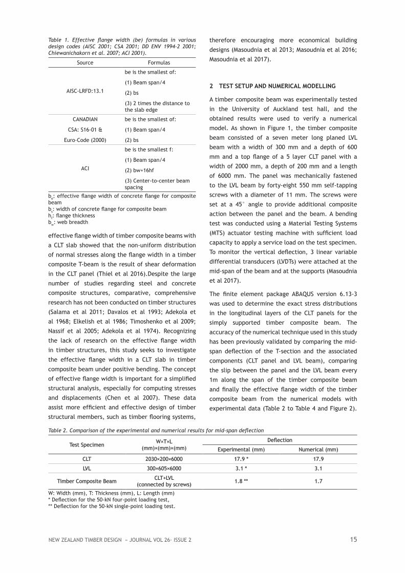
Table 1. Effective flange width (be) formulas in various design codes (AISC 2001; CSA 2001; DD ENV 1994-2 2001; Chiewanichakorn et al. 2007; ACI 2001).
Source Formulas
AISC-LRFD:13.1
be is the smallest of:
(1) Beam span/4
(2) bs
(3) 2 times the distance to the slab edge
CANADIAN
CSA: S16-01 &
Euro-Code (2000)
be is the smallest of:
(1) Beam span/4
(2) bs
ACI
be is the smallest f:
(1) Beam span/4
(2) bw+16hf
(3) Center-to-center beam spacing
be: effective flange width of concrete flange for composite beambs: width of concrete flange for composite beamhf: flange thicknessbw: web breadth

VOL 26· ISSUE 2 » NEW ZEALAND TIMBER DESIGN JOURNAL16
Table 3. Comparison of the experimental and the numerical slip results
LVDT Position of the LVDT Slip (mm) (Experimental)* Slip (mm) (Numerical)*
1 At mid-span 0 0
2 1 m from mid-span 0.056 0.055
3 2 m from mid-span 0.084 0.085
4 3 m from mid-span 0.121 0.122
* Deflection for the 50-kN single-point loading test
Table 4. Comparison of the experimental and numerical results of effective flange width
Specimen Effective flange width (Experimental)
Effective flange width (Numerical)
(Experimental result)(Numerical result)
CLT composite beam 980 mm 995 mm 0.98
The close agreement shown by these results confirms
that the model is sufficiently precise to determine the
effective flange width of the timber composite beam
(Masoudnia et al 2017; ABAQUS 2014 ).
3 NUMERICAL PARAMETRIC STUDY
This study focuses on the CLT panel configurations
and their effect on the effective flange width. The
experimentally validated numerical model was used
to study the effects of varying the characteristics of
the longitudinal and transverse layers of the CLT panel
in combination with the LVL beam on the effective
flange width of timber composite beams. Various
thicknesses of CLT panels constructed of boards with
a modulus of elasticity of 6 GPa, 8 GPa or 10 GPa were
investigated. Table 5 summarizes the specifications
and the obtained effective flange widths for the
timber composite beams.
3.1 The Effect of the Transverse Layer Thickness on the Effective Flange Width
Figure 3 illustrates the effect of different thicknesses
of transverse layers on the effective flange widths
in simply supported 6 m long beams under a single
vertical load. The thickness variation of the transverse
layers was considered for CLT panels with an elastic
modulus of 6 GPa, 8 GPa and 10 GPa. This figure shows
that increasing the depth of the transverse layer
to greater than the depth of the longitudinal layer
significantly increases the effective flange width. For
instance, when 40 mm thick longitudinal layers are
replaced by 20 mm thick layers, the effective flange
width increases by approximately 2.5 times, from
790 mm to 1880 mm (specimens No. 1 and No. 4 in
Table 5). Furthermore, the effect of the modulus of
elasticity of the CLT timber boards is presented in
Figure 3 and Table 5. Figure 3 shows that the effective
flange width generally increases by approximately 5 %
when the modulus of elasticity of the boards increases
from 6 GPa to 8 GPa. For instance, when the modulus
of elasticity of the CLT panel increases from 6 GPa
(specimen No. 8 in Table 5) to 8 GPa (specimen No. 4
in Table 5), the effective flange width increases from
1880 mm to 1950 mm.
3.2 Effect of Wood Plank Characteristics on the Effective Flange Width
To consider the effect of the CLT panel wood plank
widths on the effective flange width of the timber
composite beams, two beam configurations were
modeled using a 5-layer CLT with 90-mm or 180-mm
wide boards with a modulus of elasticity of 6 GPa, 8
GPa or 10 GPa. Various combinations of 40-mm-thick
and 20-mm-thick layers were modeled to study the
effect of the two wood plank widths on the effective
flange width. Figure 4 shows that the effective flange
width increased when a CLT panel with 90-mm-wide
boards was replaced by a CLT panel with 180-mm-
wide boards.
The maximum difference in the effective flange width
among all twenty-four numerical analysis results was
observed between configurations 14 and 20 (Table
5). This significant change was due to two factors:
the lower ratio of the transverse layer depth to the
longitudinal layer depth in the CLT panel combined
with the higher modulus of elasticity in configuration
20 and the use of smaller width boards in the CLT
panel in configuration 14. These changes led to a 560%
difference in the effective flange width of these two
specimens.
The presented results in Figure 3 and Figure 4 show
that increasing the CLT thickness has a positive effect
on the effective flange width only when the increase is
the result of increasing the thickness of the transverse
layers.

NEW ZEALAND TIMBER DESIGN » JOURNAL VOL 26· ISSUE 2 17
(a)
6000mm
200mm 2000mm
(b)
(c)
(d) (c)
(e)
(f)
(g)
(h)
(b)
Figure 1: General test setup of the timber composite beam during the bending test. (a) CLT panel; (b) LVDT at the supports; (c) LVDT at the mid-span; (d) Arrangement of the portal gauges on the surface of the CLT panel; (e) MTS machine; (f) Data acquisition system; (g) LVL beam; (h) Roller support.
Figure 2: Slip monument for every 1m along the span of the timber composite beam (Elevation).

VOL 26· ISSUE 2 » NEW ZEALAND TIMBER DESIGN JOURNAL18
Table 5. Specifications and effective flange width (mm) of the timber composite beams
Configuration CLT (mm)W×T1×L
CLT (GPa)EL1, EL2, EL3, EL4, EL5
2LVL (mm)W×T×L
LVL (GPa)MoE
Predicted effectivewidth flange (mm)
1 2000×200×60002000×(40b+40b+40b+40b+40b)
1×6000 8, 8, 8, 8, 8 2 300×600×6000 11 790
2 2000×160×60002000×(40b+20b+40b+20b+40b)×6000 8, 8, 8, 8, 8 300×600×6000 11 460
3 2000×100×60002000×(20b+20b+20b+20b+20b)×6000 8, 8, 8, 8, 8 300×600×6000 11 1055
4 2000×140×60002000×(20b+40b+20b+40b+20b)×6000 8, 8, 8, 8, 8 300×600×6000 11 1950
5 2000×200×60002000×(40b+40b+40b+40b+40b)×6000 6, 6, 6, 6, 6 300×600×6000 11 760
6 2000×160×60002000×(40b+20b+40b+20b+40b)×6000 6, 6, 6, 6, 6 300×600×6000 11 440
7 2000×100×60002000×(20b+20b+20b+20b+20b)×6000 6, 6, 6, 6, 6 300×600×6000 11 1015
8 2000×140×60002000×(20b+40b+20b+40b+20b)×6000 6, 6, 6, 6, 6 300×600×6000 11 1880
9 2000×200×60002000×(40s+40s+40s+40s+40s)×6000 8, 8, 8, 8, 8 300×600×6000 11 710
10 2000×160×60002000×(40s+20s+40s+20s+40s)×6000 8, 8, 8, 8, 8 300×600×6000 11 410
11 2000×100×60002000×(20s+20s+20s+20s+20s)×6000 8, 8, 8, 8, 8 300×600×6000 11 945
12 2000×140×60002000×(20s+40s+20s+40s+20s)×6000 8, 8, 8, 8, 8 300×600×6000 11 1755
13 2000×200×60002000×(40s+40s+40s+40s+40s)×6000 6, 6, 6, 6, 6 300×600×6000 11 680
14 2000×160×60002000×(40s+20s+40s+20s+40s)×6000 6, 6, 6, 6, 6 300×600×6000 11 390
15 2000×100×60002000×(20s+20s+20s+20s+20s)×6000 6, 6, 6, 6, 6 300×600×6000 11 905
16 2000×140×60002000×(20s+40s+20s+40s+20s)×6000 6, 6, 6, 6, 6 300×600×6000 11 1690
17 2000×200×60002000×(40b+40b+40b+40b+40b)×6000 10, 10, 10, 10, 10 300×600×6000 11 985
18 2000×160×60002000×(40b+20b+40b+20b+40b)×6000 10, 10, 10, 10, 10 300×600×6000 11 575
19 2000×100×60002000×(20b+20b+20b+20b+20b)×6000 10, 10, 10, 10, 10 300×600×6000 11 1315
20 2000×140×60002000×(20b+40b+20b+40b+20b)×6000 10, 10, 10, 10, 10 300×600×6000 11 2440
21 2000×200×60002000×(40s+40s+40s+40s+40s)×6000 10, 10, 10, 10, 10 300×600×6000 11 885
22 2000×160×60002000×(40s+20s+40s+20s+40s)×6000 10, 10, 10, 10, 10 300×600×6000 11 365
23 2000×100×60002000×(20s+20s+20s+20s+20s)×6000 10, 10, 10, 10, 10 300×600×6000 11 1180
24 2000×140×60002000×(20s+40s+20s+40s+20s)×6000 10, 10, 10, 10, 10 300×600×6000 11 2185
1 The numbers in the parentheses are the thicknesses of the individual CLT layers.2 The 5 numbers are the modulus of elasticity of each CLT layer.
b This index next to the numbers in parentheses indicates that the width of the wood plank is 180mm.
s This index next to the numbers in parentheses indicates that the width of the wood plank is 90 mm.MoE & E indicate the modulus of elasticity (units are GPa).

NEW ZEALAND TIMBER DESIGN » JOURNAL VOL 26· ISSUE 2 19
Figure 3: Effect of the layers configuration and CLT material properties on the effective flange width.
Figure 4: Effect of the CLT wood plank width on the effective flange width of timber composite beams.

VOL 26· ISSUE 2 » NEW ZEALAND TIMBER DESIGN JOURNAL20
Figure 5: Comparison of the effective flange width, CLT cost and EI of timber composite beams.
Figure 5 compares the effective flange width, CLT cost
and bending stiffness (EI) of three timber composite
beams. A 33 cm and a 149 cm increase in the effective
flange width was observed between configuration
2 and configurations 1 and 4, respectively; these
increases led to 42% and 14% reductions in CLT cost,
respectively. Moreover, the CLT layer arrangement
in configuration 4 increased the EI of the section
by 8% and 7% compared to configurations 2 and 1,
respectively.
4 PROPOSED FORMULA FOR THE EFFECTIVE FLANGE WIDTH OF TIMBER COMPOSITE BEAMS
A formula for calculating the effective flange width
(beff) of timber composite beams is proposed based
on the results of the parametric numerical study. The
formula can be used to predict the effective flange
width of timber composite beams constructed with
CLT panels of various layer configurations, material
properties and plank widths and varying span lengths
under an applied service load. All materials are
assumed to remain in the elastic phase.
Figure 6a and Figure 6b compare the effective flange
widths calculated using equation 1 and equation 2 and
their corresponding results obtained from numerical
analyses for timber composite beams constructed of
6-GPa, 8-GPa or 10-GPa CLT panels with two different
board widths. The comparison shows a maximum
difference of 9.8% between the calculations and the
numerical results, which confirms that the formula is
sufficiently precise for predicting the effective flange
width.
beff = minimum (beff (single beam), width of CLT panel) in mm (Eq 1)
beff (single beam)=(Eq 2)
α (coefficient of material properties) =
β (coefficient of plank width) =
0.95 if MoE=6 GPa1.00 if MoE=8 GPa1.30 if MoE=10 GPa
0.915 if plank width=90 mm1.000 if plank width=180 mm
* Interpolate if modulus of elasticity is between the values given.** Interpolate if width is between 90 mm and 180 mm.
5 THE EFFECT OF THE SHEAR STIFFNESS OF THE CONNECTOR ON THE EFFECTIVE FLANGE WIDTH
To investigate the effect of the shear stiffness
on the effective flange width, a series of screws
was removed, and the effective width flange was
measured experimentally. The obtained result was

NEW ZEALAND TIMBER DESIGN » JOURNAL VOL 26· ISSUE 2 21
Figure 6: Comparison of the results from the proposed formula and numerical model for 6-m-long timber composite beams: (a) CLT panel with 180-mm-wide boards, (b) CLT panel with 90-mm-wide boards.
(a) (b)
Table 6. Effect of screw shear connectors on the effective flange width
Composite action
Number ofscrews
Effective flange widthExperimental Result (mm)
Effective flange widthNumerical Result (mm)
100% 40 980 995
80%* 32 862 878
50% 20 685 702
30%** 12 510 523
* Close to 25% reduction ** Close to 75% reduction
then compared with the corresponding numerical
model. The slip variation measurement shows that 40
is the minimum number of screws that can provide
fully composite action between the CLT panel and
LVL beam. Therefore, the effective flange width was
measured experimentally when the CLT panel and LVL
beam were connected with 30, 20 and 10 screws to
simulate 75%, 50% and 25% composite action in the
timber composite beam. The summarized results
in Table 6 show that the number of screw shear
connectors significantly affected the effective flange
width of the timber composite beams. A reduction
of screw shear connectors by 20%, 50% and 70%
decreased the effective flange width by 20%, 30% and
48%, respectively.
In addition, the calculated effective bending stiffness
(EI) with the effective flange width results from the
numerical analysis and recommended formula were
compared with the calculated effective bending
stiffness with the gamma method, as shown in Figure
7. The comparison shows that the bending stiffness
obtained by the gamma method is overdesigned
compare with the obtained results based on the
numerical analysis and formula.
6 THE EFFECT OF THE CLT LAYERS CONFIGURATION ON THE EFFECTIVE FLANGE WIDTH OF TIMBER COMPOSITE BEAMS WITH EQUAL CLT THICKNESS
The effect of the layers configuration has been
investigated for two timber composite beams which are
comprised of a CLT panel with equal overall thickness
but with different configurations of longitudinal and
transverse layers (Figure 8a and Figure 8b). Figure 8a
shows a comparison of specimen No.6 and specimen
E. Both are 160 mm thick. In specimen No.6, the
panel is comprised of 40 mm longitudinal layers and
20 mm transverse layer and specimen E CLT panel is
constructed of 20 mm longitudinal layer and 50 mm
transverse layers. The comparison shows that using
thicker longitudinal layer in specimen No.6 leads to
a 75 % decrease in effective flange width compare to
the specimen E effective width, although the overall
CLT thickness remain similar.
7 CONCLUSIONS
The objective of this study was to understand the
parameters that affect the effective width of a CLT
slab in a timber composite beam. A full-scale timber

VOL 26· ISSUE 2 » NEW ZEALAND TIMBER DESIGN JOURNAL22
Figure 7: Comparison of the calculated bending stiffness (EI) of timber composite beam (specimen No.5) based on Gamma method (A), Gamma method (B), numerical analysis (C) and recommended formula (D).* Only Three longitudinal layers in CLT was used to calculate the moment of inertial** Whole section consider in moment of inertia calculation
(a) (b)
Figure 8: Effect of the CLT layers configuration on the effective flange width of timber composite beams for MoE of 6 GPa and with equal CLT thickness (a) CLT thickness at 160 mm, (b) CLT thickness at 200 mm.
composite beam was tested experimentally, and
a numerical model of the timber composite beam
with actual geometric and material properties was
developed to estimate the effective flange width.
The accuracy of the proposed 3D numerical model of
the timber composite beam was verified considering
mid-span deflection, the effective flange width and
the slip between the CLT panel and the LVL beam.
The close agreement between the numerical results
and the corresponding experimental tests confirmed
that the numerical model is sufficiently accurate
for determining the CLT effective flange width. The
numerical model was then used to conduct a parametric
analysis of the timber composite beams. The effective
flange widths of various timber composite beams were
extensively studied considering various arrangements,
widths, thicknesses and modulus of elasticity values for
the CLT boards. The effective flange width increased
with any changes that increased the ratio of the
transverse layer depth to the longitudinal layer depth.

NEW ZEALAND TIMBER DESIGN » JOURNAL VOL 26· ISSUE 2 23
Moreover, using thicker longitudinal layers in similar
thickness of the CLT slab decreases the effective
flange width. Furthermore, stiffer transverse layers in
CLT panels with a higher modulus of elasticity slightly
improved the effective flange width. The maximum
improvement in the effective flange width in timber
composite beams was the result of using CLT panels
with wider and thicker boards, with higher modulus of
elasticity values, and with the maximum ratio of the
transverse layer thickness to the longitudinal layer
thickness. In addition, the results showed that an
ideal layer arrangement in timber composite beams
can notably increase the strength of the section and
can significantly reduce the materials consumed and
associated costs. Finally, a formula was proposed
for predicting the effective flange width of timber
composite beams and validated for a span varying
between 6 m and 10 m, a Young's modulus between 6
GPa and 10 GPa and a plank width between 90 mm and
180 mm. In addition, the formula is only applicable
when the transverse and longitudinal layers have
the same material properties. Therefore, additional
parametric studies are required to consider the effect
of boards with different mechanical and geometrical
properties.
ACKNOWLEDGMENTS
The authors would like to thank the laboratory
technicians, Mark Byrami and Andrew Virtue, for their
contribution in preparing the test setup. Gratitude is
extended to Prof. Hans Joachim Blass for providing
ideas and support with ABAQUS. Finally, the authors
thank photographer and graphic designer, Nariman
Valizadeh and Navid Masoudnia for providing great
photos and figures.
REFERENCES
Amadio, C., and Fragiacomo, M. (2002). “Effective
width evaluation for steel-concrete composite
beams.” J. Constr. Steel Res., 58(3), 373–388.
Aref, A. J., Chiewanichakorn, M., Chen, S. S., and Ahn, I.
S. (2007). “Effective slab width definition for negative
moment regions of composite bridges.” J. Bridge Eng.,
10.1061/(ASCE)1084-0702(2007)12:3(339), 339–349.
Zou, B., Chen, A., Davalos, J. F., and Salim, H. A.
(2011). “Evaluation of effective flange width by shear
lag model for orthotropic FRP bridge decks.” Comp.
Struct., 93(2), 474–482.
Castro, J. M., Elghazouli, A. Y., and Izzuddin, B.
A. (2007). “Assessment of effective slab widths in
composite beams.” J. Constr. Steel Res., 63(10),
1317–1327.
Salama, T., and Nassifb, H. (2011). “Effective flange
width for composite steel beams.” J. Eng. Res., 8(1),
28–43.
AISC. (2001). Manual of steel construction: Load and
resistance factor design, American Institute of Steel
Construction, Inc., Chicago, IL.
CSA (Canadian Standards Association). (2001). Limit
state design of steel structures-CAN/CSA-S16-01, CSA,
Rexdale, Ont., Canada.
DD ENV 1994-2:2001, Eurocode 4. (1994). Design
of composite steel and concrete structures. Part
2: Composite bridges and Part 1.1, general rules
and rules for buildings, British Standard Institution,
London.
Porteous, J., and Kermani, A. (2013). Structural
timber design to Eurocode 5, John Wiley & Sons,
Chichester, UK.
Ozelton, E., and Baird, J. (2008). Timber designers’
manual, C. L. Staples, London, UK.
Thiel, A., Brandner, R. (2016). “ULS design of CLT
Elements-basics and some Special Topics”, Proceeding
of the joint conference of COST actions FP1402 &
FP1404 KTH building materials.
Chen, S. S., Aref, A. J., Chiewanichakorn, M., and Ahn,
I. S. (2007). “Proposed effective width criteria for
composite bridge girders.” J. Bridge Eng., 10.1061/
(ASCE)1084-0702(2007)12:3(325), 325–338.
Chiewanichakorn, M., Aref, A. J., Chen, S. S., and
Ahn, I. S. (2004). “Effective flange width definition
for steel-concrete composite bridge girder.” J. Struct.
Eng., 10.1061/(ASCE)0733-9445(2004)130:12(2016),
2016–2031.
Davalos, J. F., and Salim, H. A. (1993). “Effective
flange width for stress-laminated T-system timber
bridges.” J. Struct. Eng., 10.1061/(ASCE)0733-
9445(1993)119:3(938), 938–953.
Adekola, A. O. (1968). “Effective widths of composite
beams of steel and concrete.” Struct. Eng., 46(9),
285–289.
Elkelish, M. S., and Robinson, H. (1986). “Longitudinal

VOL 26· ISSUE 2 » NEW ZEALAND TIMBER DESIGN JOURNAL24
cracking of composite beams with ribbed metal deck.”
Can. J. Civ. Eng., 13(6), 733–740.
Timoshenko, S., and Gere, J. (2009). “Theory of elastic
stability”. Courier Dover Publications, Mineola, NY.
Nassif, H., Abu-Amra, T., and El-Tawil, S. (2005).
“Effective flange width criteria for composite steel
girder bridges.” Proc., Transportation Research Board
84th Annual Meeting. Paper No. 05-2477.
Masoudnia, R. (2013). Stub girder flooring system
for timber construction, Provisional Report, The
University of Auckland, Auckland, New Zealand.
Masoudnia, R., Hashemi, A., and Quenneville, P.
(2016). “Evaluation of effective flange width in the
CLT composite T-beams.” Proc., World Conf. on
Timber Engineering, Vienna, Austria.
Masoudnia, R., Hashemi, A., and Quenneville, P.
(2017). “Predicting the effective flange width of
a CLT slab in timber composite beams.” Journal of
Structural Engineering, 144 (7), 04018084.
Masoudnia, and Quenneville, P. (2017). “Improvements
to timber composite beams.” Provisional patent
number 731716.
Adekola, A. O. (1974). “The dependence of shear lag
on partial interaction in composite beams.” Int. J.
Solids Struct., 10(4), 389–400.
ACI (American Concrete Institute). (2002). “Building
code requirements for reinforced concrete.” AISC,
318-02 2001, Manual of steel construction: Load and
resistance factor design, American Institute of Steel
Construction, Inc., Chicago, IL.
ABAQUS. (2014). Theory manual, version 6.13. Hibbitt,
Karlsson & Sorensen, Inc., Pawtucket, RI.