Evaluation of Cryptographic CRC in 65nm CMOS
63
IN DEGREE PROJECT INFORMATION AND COMMUNICATION TECHNOLOGY, SECOND CYCLE, 30 CREDITS , STOCKHOLM SWEDEN 2017 Evaluation of Cryptographic CRC in 65nm CMOS YANG YU KTH ROYAL INSTITUTE OF TECHNOLOGY SCHOOL OF INFORMATION AND COMMUNICATION TECHNOLOGY
Transcript of Evaluation of Cryptographic CRC in 65nm CMOS

IN DEGREE PROJECT INFORMATION AND COMMUNICATION TECHNOLOGY,SECOND CYCLE, 30 CREDITS
, STOCKHOLM SWEDEN 2017
Evaluation of Cryptographic CRC in 65nm CMOS
YANG YU
KTH ROYAL INSTITUTE OF TECHNOLOGYSCHOOL OF INFORMATION AND COMMUNICATION TECHNOLOGY
Evaluation of Cryptographic CRCin 65nm CMOS
YANG YU
Stockholm 2017
Master ThesisSchool of Information and Communication Technology
KTH Royal Institute of Technology


Abstract
With the rapid growth of Internet-of-Things (IoT), billions of devices are expected tobe interconnected to provide various services appealing to users. Many devices willget an access to valuable information which is likely to increase the number ofmalicious attacks on these devices in the future. Therefore, security is considered asone of the most critical challenges in the development of IoT. In order to secureresource-constrained devices such as sensors or radio frequency identification (RFID)tags which form the backbone of IoT, lightweight cryptographic algorithms arerequired. This thesis focuses on the problem of message authentication.
To authenticate a message means to verify that the message: (1) comes from theright sender (i.e. its authenticity), and (2) has not been modified (i.e. its integrity). It ischallenging to use traditional message authentication methods in resource-constraineddevices because typically they can allocate only a few hundred gates for implementingsecurity due to their limited computing, storage and energy resources.
To address these needs, a new message authentication algorithm based on aCryptographic Cyclic Redundancy Check (C-CRC) was developed by KTH incollaboration with Ericsson. In this thesis, we implemented C-CRC and compared itwith KECCAK Message Authentication Code (KMAC) standardized by the NationalInstitute of Standards and Technology (NIST) in 2016.
First, MATLAB and Verilog versions were developed for both algorithms. Thecomparison of these two versions allowed us to verify the correctness of algorithmsfunctionality. After that, the Verilog descriptions were simulated in ModelSim andsynthesized using Synopsys design compiler. Finally, placement and routing wasperformed using Cadence SoC Encounter. The evaluation results show that C-CRCoutperforms KMAC in terms of area, power, throughput per area, and energy per bit.However, C-CRC is worse than KMAC in terms of latency. We have also investigatedseveral different options of implementing C-CRC, including producing more than onebit of output per clock cycle. We found that such a technique improves throughput ofC-CRC with the minimal penalty in area and power consumption.
Keywords— MAC, KMAC, cryptographic CRC, Simulation, Verilog HDL, MATLAB


Acknowledgment
First of all, I would like to thank my examiner, Professor Elena Dubrova, for givingme the chance to join this interesting topic. She also inspired me to keep questioningand studying since I took her course in 2015.
Secondly, I want to express my sincere gratitude to my supervisor Ms. Sha Tao forhelp and kindness at all times. She gave me considerable advices at almost every stepof this thesis.
Thirdly, I am much obliged to Professor Gerald Q Maguire Jr, the course examinerof Research Methodology and Scientific Writing. He not only taught me what to dobut also how to do.
Fourthly, I would like to thank Mr. John Mattsson, from Ericsson, for attendingthe mid-term presentation and giving me many pivotal suggestions.
A big thanks goes to my programme coordinator and friends at the school of ICT,Ms. May-Britt Eklund Larsson.
Last but not the least, I would like to thank my family and my friends in Sweden.
iii


Contents
1 Introduction 11.1 Previous Work . . . . . . . . . . . . . . . . . . . . . . . . . . . . . . 21.2 Contribution . . . . . . . . . . . . . . . . . . . . . . . . . . . . . . . 31.3 Performance Metrics . . . . . . . . . . . . . . . . . . . . . . . . . . 31.4 Thesis Organization . . . . . . . . . . . . . . . . . . . . . . . . . . . 4
2 Overview of KMAC and C-CRC 52.1 KMAC . . . . . . . . . . . . . . . . . . . . . . . . . . . . . . . . . 5
2.1.1 KECCAK[256] Sponge Function . . . . . . . . . . . . . . . . . 62.1.2 KECCAK - f [1600] Permutation Function . . . . . . . . . . . . 7
2.2 C-CRC . . . . . . . . . . . . . . . . . . . . . . . . . . . . . . . . . 11
3 Implementation and Evaluation 143.1 MATLAB Implementation . . . . . . . . . . . . . . . . . . . . . . . 15
3.1.1 C-CRC Implementation in MATLAB . . . . . . . . . . . . . 153.1.2 KMAC128 Implementation in MATLAB . . . . . . . . . . . 15
3.2 ASIC Design . . . . . . . . . . . . . . . . . . . . . . . . . . . . . . 173.2.1 Variable Specification . . . . . . . . . . . . . . . . . . . . . 173.2.2 KMAC128 Implementation in HDL . . . . . . . . . . . . . . 183.2.3 C-CRC Implementation in HDL . . . . . . . . . . . . . . . . 203.2.4 Simulation Results and Analysis . . . . . . . . . . . . . . . . 223.2.5 Layout . . . . . . . . . . . . . . . . . . . . . . . . . . . . . 23
4 Discussion and Conclusion 254.1 Implementation of Alternative Specification . . . . . . . . . . . . . . 254.2 Implementation of Special Constraints . . . . . . . . . . . . . . . . . 26
4.2.1 Latency Constraint . . . . . . . . . . . . . . . . . . . . . . . 264.2.2 Power Constraint . . . . . . . . . . . . . . . . . . . . . . . . 28
4.3 Conclusion . . . . . . . . . . . . . . . . . . . . . . . . . . . . . . . 284.4 Future Work . . . . . . . . . . . . . . . . . . . . . . . . . . . . . . . 29
A Verilog HDL Transcript 32A.1 KMAC . . . . . . . . . . . . . . . . . . . . . . . . . . . . . . . . . 32A.2 C-CRC with parallel output . . . . . . . . . . . . . . . . . . . . . . . 44
v

List of Figures
1.1 Increasing connectivity across people and devices. . . . . . . . . . . . 1
2.1 The data flow diagram of KMAC128 . . . . . . . . . . . . . . . . . . 52.2 The sponge construction of KECCAK[256] [1] . . . . . . . . . . . . . . 72.3 Illustration of θ applied to a single bit [1] . . . . . . . . . . . . . . . 82.4 Illustration of ρ for a 200 bit string [1] . . . . . . . . . . . . . . . . . 92.5 Illustration of π applied to a 5-by-5 slice [1] . . . . . . . . . . . . . . 102.6 Illustration of χ applied to a 1-by-5 row [1] . . . . . . . . . . . . . . 102.7 The data flow diagram of C-CRC . . . . . . . . . . . . . . . . . . . . 13
3.1 The project design methodology flow chart . . . . . . . . . . . . . . 143.2 C-CRC structure in MATLAB implementation . . . . . . . . . . . . . 153.3 KMAC structure in MATLAB implementation . . . . . . . . . . . . . 163.4 The adapted KMAC128 algorithm data flow diagram . . . . . . . . . 183.5 Two types of LFSR . . . . . . . . . . . . . . . . . . . . . . . . . . . 203.6 The optimized Galois LFSR with less latency . . . . . . . . . . . . . 213.7 The programmable LFSR with any generator polynomial . . . . . . . 213.8 C-CRC with two designs of the output section . . . . . . . . . . . . . 223.9 Layout of the implementations of KMAC128 and C-CRC . . . . . . . 24
4.1 The sequence diagram of KMAC128 with a longer input message . . 264.2 The data flow diagram of KMAC with round instance of two . . . . . 274.3 Power gating in LFSR of C-CRC . . . . . . . . . . . . . . . . . . . . 28
vi


List of Tables
2.1 The computation of 3-bit CRC . . . . . . . . . . . . . . . . . . . . . 12
3.1 Specifications of the identical variables . . . . . . . . . . . . . . . . . 173.2 Round constant value in little-endian and hexadecimal format . . . . . 193.3 Synthesis Results for The Proposed MAC Functions . . . . . . . . . . 233.4 Comparison of total area of core . . . . . . . . . . . . . . . . . . . . 24
4.1 Comparison in 1024 bits message length and 10MHz Clock Frequency 27
viii


Acronyms
ASIC Application-Specific Integrated CircuitCRC Cyclic Redundancy CheckGE Gate EquivalentGF Galois FieldHMAC Keyed-Hash Message Authentication CodeKAT Known Answer TestKMAC KECCAK Message Authentication CodeLFSR Linear-Feedback Shift RegisterMAC Message Authentication CodeMD Message DigestNIST National Institute of Standards and TechnologyPRF Pseudo-Random FunctionRFID Radio Frequency IDentificationSHA Secure Hash Algorithm
x


Chapter 1
Introduction
Today, we are at a turning point as embedded systems are increasingly found to beriddled with security vulnerabilities. With the trend of the Internet-of-Things (IoT), anincreasing amount of embedded devices that used to have no communicationcapabilities are integrated into large systems and thus connected to the Internet (shownin Figure 1.1). The embedded devices, especially the low-end ones, are initiallydesigned without security concerns and not able to fix the problems through themethods like updating software. The risk is raised that the attackers can gain physicalaccess to these devices and thus perform certain attacks such as side-channel attack.
Cloud
Figure 1.1: Increasing connectivity across people and devices.
Message authentication code (MAC) is a piece of code to authenticate a messagefrom the sender [2]. Compared to the hash functions, the MAC value protects not onlyintegrity but also authenticity of the message. In other words, the receiver verifies thatthe message comes from the right sender and has not been modified. In most cases,the embedded devices like sensors or RFID tags are constrained in energy and areaconsumption, computation power, memory and cost. Therefore, the solutions need tobe secure as well as efficient to implement on these devices. In consideration of theabove, we tried to find a solution to achieve error detection and data integrityprotection simultaneously with the minimal penalty in area and power consumption.

2 Introduction
1.1 Previous Work
In 1996, a new type of MAC, called keyed-hash message authentication code(HMAC) was defined and published [3]. HMAC involves a user-selected hashfunction and a preset secret key. Combined with any hash function, such as MessageDigest 5 (MD5) or Secure Hash Algorithm 1 (SHA-1), HMAC is able to verify dataintegrity and message authentication. In terms of security strength, HMAC relies onthe security strength of three main factors, including the underlying hash function, thehash output length, and the secret key length. In 2008, National Institute of Standardsand Technology (NIST) published the standard for HMAC [4].
Unfortunately, MD5 and SHA-1 are no longer considered secure in today’scomputer security environment. In 2013, a collision attack was announced which canbreak MD5 collision resistance with a regular computer in less than one second [5].On February 23rd, 2017 the first collision attack against SHA-1 was announced byGoogle and CWI Amsterdam [6]. Accordingly, new hash functions as well as newMAC functions should be taken into consideration.
In 2006, NIST started to organize a competition for a new hash standard. InDecember 2010, KECCAK [7] was selected to be the winner against other 50candidates. In 2015, NIST published the standard for the Secure Hash Algorithm-3(SHA-3) function [1], which is the official alias of KECCAK. In 2016, a new MACstandard, called KECCAK Message Authentication Code (KMAC), was published byNIST [8]. The only thing that is missing in the application of low-cost embeddedsystems is the huge area and power consumption with regard to the heavycomputation. Therefore, a light-weight with enough security-satisfaction MACfunction is what we need.
In 1961, Cyclic Redundancy Check (CRC) was published by Wesley Peterson [9].CRC is an error-detecting code which encodes messages by padding a checksum ofcertain length, commonly used within communication networks. CRC are not onlyeasy to implement in hardware but also beneficial in being particularly suitable fordetecting burst errors. In practice, an n-bit CRC applied on an arbitrary size ofmessage block will detect any single to n bits burst error. Because the checksum has afixed length, the CRC computation function can be used as a hash functionoccasionally. Nowadays, various standards of CRC have been published and appliedon billions of devices.
In 2017, a new MAC scheme was proposed by the collaboration of KTH andEricsson on the basis of the cryptographic Cyclic Redundancy Check (CRC) [10](referred as C-CRC in the following). Different from other CRC based MAC, it usesrandom rather than irreducible generator polynomials. In the security analysis of thisnew scheme, the result showed that it is particularly suitable for short messages (up toa few tens of bytes). That paper also showed interest in combining the build-in CRCsection of devices with C-CRC.

1.2 Contribution 3
1.2 ContributionThis thesis presents the implementation of KMAC and C-CRC in 65nm CMOS, andcompares them using performance metrics. MATLAB and Verilog versions areimplemented for both of the algorithms. With the comparison between these twoversions’ simulation, the algorithms’ functionality are validated together with the testvectors provided by NIST. After that, the two functions were synthesized, and thesimulation results are evaluated and analyzed. Finally, to provide a morecomprehensive conclusion, the influence of specification and special constraints ontwo functions were under discussion. With the discussion, the following study couldeasily compare the two functions without actually implementing them.
1.3 Performance MetricsGenerally, area and power is the most significant indexes for embedded devices,especially the low end ones. With concern for the efficiency of area and power,throughput per area and energy per bit are listed besides the common performancemetrics . All the comparison should be performed within the same manufacturingtechnology and environment, as well as the input specification and simulationprocedure.
Area
The metric ”area” stands for the total area of implemented circuit, including the area ofcells and interconnections. Throughout this thesis, micrometer (µm) rather than GateEquivalent (GE) is used as the primary measure for circuit area. In application-specificintegrated circuit (ASIC) design, GE is define as the area of a two-input NAND gateindependently of the manufacturing technology. In our project, 1 GE is equal to 1.44µm2 according to the applied technology databook [11]. The values of area given bythe synthesis tool are presented in GE. To give an intuitive comparison, the values aretransfered into micrometers instead.
Power
”Power” is another important metric especially in embedded devices. The constrainton power consumption results from the limitation from the applied technology and therequest for extra functionality or increased working time. Both the overall static powerconsumption (same in both measurements), and the dynamic power consumption ofthe I/O interface have been subtracted. The ”total power” in this thesis corresponds tothe sum of dynamic power and cell leakage power. To be noticed, the power valuesmay differ under different operating voltages for the same design.
Latency
”Latency” is the duration from the beginning of an input message injected to the endof the corresponding output string obtained. This metric represents the requiredprocessing time of one input message regardless of whether messages can beprocessed at the same time. In this section, each implementation is considered in their

4 Introduction
best performance. Only the previous rounds of the very long messages are taken intoconsideration. The effects of the finalization and communication stages are neglected.
Throughput
The metric ”throughput” is defined as the maximum output bits for eachimplementation can be produced per unit time. This value only counts when theoutput is active. With this value together with latency, we can decide which one is theperformance bottleneck of the implementation. The throughput values are given inmega (106) bits per second (Mbit/s).
Energy per Bit
”Energy per Bit” represents efficiency in power consumption per output string bit.
energy per bit =power
throughput(1.1)
Throughput per Area
”Throughput per Area” represents efficiency in throughput per area consumption.
throughput per area =throughput
area(1.2)
1.4 Thesis OrganizationThe main object of this thesis project is to implement and evaluate C-CRC in 65nmand compare its performance with KMAC. Throughout the thesis, the two MACfunctions were implemented first in MATLAB then in HDL. Next, the simulationresults of two MAC functions were analyzed and compared. Finally, a discussion ofthe implementations of various input parameter specification and special constraintsare presented at the end of this thesis report.
Chapter 2 gives a brief introduction of KMAC and C-CRC algorithm. KMAC isintroduced step by step due to its multi-layer structure. The introduction of C-CRCfocuses on CRC and its computation.
Chapter 3 shows the detailed implementation of KMAC128 and C-CRC, includingMATLAB and HDL versions. After that, their simulation results are presented andcompared with each other. Finally, the layout and the reported total core area areshown.
Chapter 4 presents the discussion of the KMAC and C-CRC alternativeimplementations of various input parameter specification and special constraints. Atlast, the final conclusion are drawn with several suggestions for future work.

Chapter 2
Overview of KMAC and C-CRC
By definition, the output of MAC functions is produced by two independent inputparameters, which are the message and the secret key. Normally, the length of the keyhas certain influence on the security level of MAC. In this chapter, the algorithm-levelintroductions of KMAC and C-CRC are presented in their original definitions. On thebasis of this, the proposed functions are reorganized and implemented in Chapter 3.
2.1 KMACIn FIPS PUB 202, KECCAK was introduced. The KECCAK algorithm is a family of allsponge functions with a KECCAK− f permutation as the underlying function andmulti-rate padding as the padding rule. As the name suggests, KMAC is also builtfrom the KECCAK algorithm. In order to illustrate the definition of KMAC, thefollowing subsections are structured in the top-down construction.
The KMAC function is a pseudo-random function (PRF) and keyed hash functionon the basis of the KECCAK. For different security strength requirements, there are twovariants of KMAC, KMAC128 and KMAC256. Take into account both theapplication area and balanced security strength with C-CRC, KMAC128 is adopted inthis thesis. To give an intuitive review of the algorithm, KMAC128 is transformed intothe data flow diagram in Figure 2.1.
EncryptionKey
Message
T || newM || 00
Customized String
KECCAK[256]
Figure 2.1: The data flow diagram of KMAC128
The following parameters are used in KMAC128 definition:
• K : a key bit string of at least the required security length
6 Overview of KMAC and C-CRC
• M : the input message bit string
• L : an integer representing the required output length in bits
• S : the customization bit encryption string of any length, including null
Algorithm 2.1 KMAC128(K,M,L,S)Input: K,M,L,SOutput: Z, len(Z) = len(L)
newM = bytepad(encode string(K),168)‖M ‖ right encode(L)T = bytepad(encode string(”KMAC”)‖encode string(S),168)Z = KECCAK[256](T ‖newM ‖00,L)
Three internal functions, right encode, encode string and bytepad, are used toencode the intermediate values. right encode(x) encodes the input integer x as a bytestring and inserts the length of the string after (on the right of) the representing stringof x. encode string(S) utilizes a similar function as right encode and inserts theencoding before (on the left of) S. bytepad(X ,w) adds an le f t encode(w) to the stringX , then pads the result with zeros until it is a byte string whose length in bytes is amultiple of w.
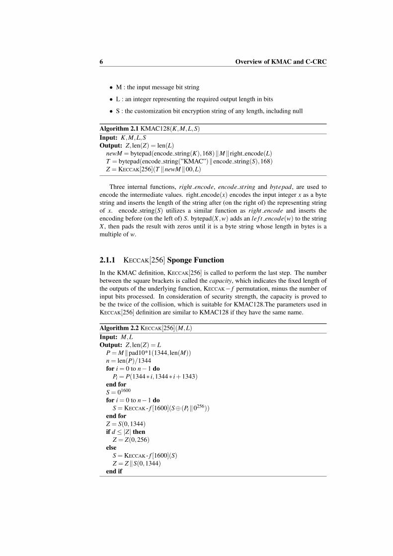
2.1.1 KECCAK[256] Sponge FunctionIn the KMAC definition, KECCAK[256] is called to perform the last step. The numberbetween the square brackets is called the capacity, which indicates the fixed length ofthe outputs of the underlying function, KECCAK− f permutation, minus the number ofinput bits processed. In consideration of security strength, the capacity is proved tobe the twice of the collision, which is suitable for KMAC128.The parameters used inKECCAK[256] definition are similar to KMAC128 if they have the same name.
Algorithm 2.2 KECCAK[256](M,L)Input: M,LOutput: Z, len(Z) = L
P = M ‖pad10*1(1344, len(M))n = len(P)/1344for i = 0 to n−1 do
Pi = P(1344∗ i,1344∗ i+1343)end forS = 01600
for i = 0 to n−1 doS = KECCAK - f [1600](S⊕(Pi ‖0256))
end forZ = S(0,1344)if d ≤ |Z| then
Z = Z(0,256)else
S = KECCAK - f [1600](S)Z = Z ‖S(0,1344)
end if

2.1 KMAC 7
KECCAK[256] is constructed by three components, the underlying function,KECCAK - f , the capacity and the padding rule, pad10*1. KECCAK[256] is called asponge function in FIPS PUB 202. The analogy to a sponge is that an arbitrary lengthof input message (len = 1600−256) is ”absorbed” into the underlying function, afterwhich the same length of output string is ”squeezed” out of the underlying function.This denotation is illustrated in Figure 2.2.
Figure 2.2: The sponge construction of KECCAK[256] [1]
2.1.2 KECCAK - f [1600] Permutation Function
The parameter specifies KECCAK - f permutation function, called the width, whichsuggests the maximum length of the strings that can be processed each time. Anomitted parameter, called the round, is defined to be 24 in default. Put differently,every KECCAK - f [1600] function call consists of 24 rounds of permutation. In eachround, a similar routine is performed with a different value, called the round constant.
A conversion from the input string to a 5-by-5-by-64 array, called the state array,acts as the first step of permutation. Next, five functions, called the step mapping, areperformed in order on the state array. At last, a reverse of the first step are executed toachieve the final output.
The first step mapping is called θ . The illustration of applying function θ to asingle bit in the state array shown in Figure 2.3.

8 Overview of KMAC and C-CRC
Figure 2.3: Illustration of θ applied to a single bit [1]
Algorithm 2.3 θ(A)Input: state array AOutput: state array A′
for x = 0 to 4 dofor z = 0 to 63 do
C(x,z) = A(x,0,z)⊕A(x,1,z)⊕A(x,2,z)⊕A(x,3,z)⊕A(x,4,z)end for
end forfor x = 0 to 4 do
for z = 0 to 63 doD(x,z) =C((x−1) mod 5,z)⊕C((x+1) mod 5,(z−1) mod 64)
end forend forfor x = 0 to 4 do
for y = 0 to 4 dofor z = 0 to 63 do
A′(x,y,z) = A(x,y,z)⊕D(x,z)end for
end forend for

2.1 KMAC 9
The second step mapping is called ρ . The illustration of applying function ρ to a200 bit string shown in Figure 2.4.
Figure 2.4: Illustration of ρ for a 200 bit string [1]
Algorithm 2.4 ρ(A)Input: state array AOutput: state array A′
for z = 0 to 63 doA′(0,0,z) = A(0,0,z)
end for(x,y) = (1,0)for t = 0 to 23 do
for z = 0 to 63 doA′(x,y,z) = A(x,y,(z− (t +1)(t +2)/2) mod 64)(x,y) = (y,(2x+3y) mod 5)
end forend for
The third step mapping is called π . The illustration of applying function π to a5-by-5 bit slice of the state array shown in Figure 2.5.
Algorithm 2.5 π(A)Input: state array AOutput: state array A′
for x = 0 to 4 dofor y = 0 to 4 do
for z = 0 to 63 doA′(x,y,z) = A((x+3y) mod 5,x,z)
end forend for
end for

10 Overview of KMAC and C-CRC
Figure 2.5: Illustration of π applied to a 5-by-5 slice [1]
The forth step mapping is called χ . The illustration of applying function π to a1-by-5 bit row of the state array shown in Figure 2.6.
Figure 2.6: Illustration of χ applied to a 1-by-5 row [1]
Algorithm 2.6 χ(A)Input: state array AOutput: state array A′
for x = 0 to 4 dofor y = 0 to 4 do
for z = 0 to 63 doA′(x,y,z) = A(x,y,z)⊕((A((x+1) mod 5,x,z)⊕1) ·A((x+2) mod 5,y,z))
end forend for
end for
2.2 C-CRC 11
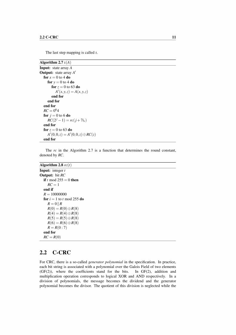
The last step mapping is called ι .
Algorithm 2.7 ι(A)Input: state array AOutput: state array A′
for x = 0 to 4 dofor y = 0 to 4 do
for z = 0 to 63 doA′(x,y,z) = A(x,y,z)
end forend for
end forRC = 064for j = 0 to 6 do
RC(2 j−1) = rc( j+7ir)end forfor z = 0 to 63 do
A′(0,0,z) = A′(0,0,z)⊕RC(z)end for
The rc in the Algorithm 2.7 is a function that determines the round constant,denoted by RC.
Algorithm 2.8 rc(t)Input: integer tOutput: bit RC
if t mod 255 = 0 thenRC = 1
end ifR = 10000000for i = 1 to t mod 255 do
R = 0‖RR(0) = R(0)⊕R(8)R(4) = R(4)⊕R(8)R(5) = R(5)⊕R(8)R(6) = R(6)⊕R(8)R = R(0 : 7)
end forRC = R(0)
2.2 C-CRCFor CRC, there is a so-called generator polynomial in the specification. In practice,each bit string is associated with a polynomial over the Galois Field of two elements(GF(2)), where the coefficients stand for the bits. In GF(2), addition andmultiplication operation corresponds to logical XOR and AND respectively. In adivision of polynomials, the message becomes the dividend and the generatorpolynomial becomes the divisor. The quotient of this division is neglected while the

12 Overview of KMAC and C-CRC
remainder is the CRC checksum. The highest index of a polynomial is called thedegree. The degree of the checksum can be therefore determined by the generatorpolynomial degree.
M(x) · xn = Q(x) ·g(x)−R(x) (2.1)
To compute an n-bit binary CRC in the mathematical way, first place the messagebits with n-bit 0 in a row, position the generator polynomial start from the left-hand ofthe message. To divide the message with the generator polynomial, bitwise XOR ofthe upper with the lower bits. The message bits not above the generator polynomialbits remain the same and are duplicated for the next step. Then, the generatorpolynomial is shifted to the right one bit, and bitwise XOR the upper bits. Thisoperation is repeated until the generator polynomial reaches the end of the message.Take message ”11010011101101” and generator polynomial ”1011” as an example,the computation is shown in Table 2.1.
11010011101101 000101101100011101101 0001011
00111011101101 0001011
00010111101101 0001011
00000001101101 0001011
00000000110101 0001011
00000000011001 0001011
00000000001111 0001011
00000000000100 000101 1
00000000000001 1001 011
00000000000000 111
Table 2.1: The computation of 3-bit CRC
In software, the polynomial division can be realized by bitwise XOR the non-zerobit in the message string. The follwing pseudo code gives the details when implement-ing CRC computation in software.

2.2 C-CRC 13
Algorithm 2.9 CRCInput: M(1 : L), g(1 : n+1)Output: R
R = 0for i = 1 to L do
R = R⊕[M(i)‖zeros(n−1)]if R(n−1) = 1 then
R = (R‖0)⊕gelse
R = R‖0end if
end for
The following parameters are used in C-CRC definition:
• M(x) : the input message polynomial
• g(x) : the generator polynomial
• S(x) : the customized polynomial
• L : the required generator polynomial degree
Algorithm 2.10 C-CRCInput: M(x), g(x), S(x), LOutput: Z(x), deg(Z) = deg(g)
Hg(x) = M(x) · xL mod g(x)Z(x) = Hg(x) + S(x)
To be pointed out, g(x) in the definition represents any generator polynomial withnon-zero constant term. To give an intuitive review of the algorithm, C-CRC is trans-formed into the data flow diagram in Figure 2.7.
CRC
ComputationGenerator Polynomial
Message
Encryption String
Encryption
Figure 2.7: The data flow diagram of C-CRC

Chapter 3
Implementation and Evaluation
The implementation of two algorithms consists of two main parts, includingMATLAB implementation and ASIC design. First, the proposed messageauthentication functions are implemented with their original definitions usingMATLAB. Next, a typical ASIC design flow is performed to obtain the circuits andthen validated by the MATLAB version. The overall implementation methodology isillustrated as flow chart in Figure 3.1.
ASIC Design
START
HDL Design
Logic Synthesis
Rou�ng
Placement
END
Func�onal
Simula�on
Matlab
Implementa�on
Func�onal
Valida�on
Figure 3.1: The project design methodology flow chart

3.1 MATLAB Implementation 15
3.1 MATLAB Implementation
There is no available implementations or test vectors of KMAC when this projectbegan. Therefore, a validated implementation of the original algorithms are requiredto prove the correctness of the ASIC design. The reasons why MATLAB was chosenare that intermediate values can be viewed easily when testing, and there are variousbuild-in functions which can be used directly. With less self-written functions, thecodes are tested faster.
3.1.1 C-CRC Implementation in MATLAB
There are numerous available MATLAB codes of CRC implementation on the Internet.For the ordinary CRC calculation, a build-in function, called deconv, is employed toobtain the coefficients of the remainder. The first task of implementing C-CRC is to addthe generator polynomial as an additional input in order to realize the programmablefeature. Then, the coefficients are converted to GF(2) for the final result. The flowchart illustrates the C-CRC implementation in MATLAB shown in Figure 3.2.
START
[M 0length(g)-1] Mx
deconv(Mx,g) rx
r(length(M)+1:end)
mod(|rx|,2) r
END
Figure 3.2: C-CRC structure in MATLAB implementation
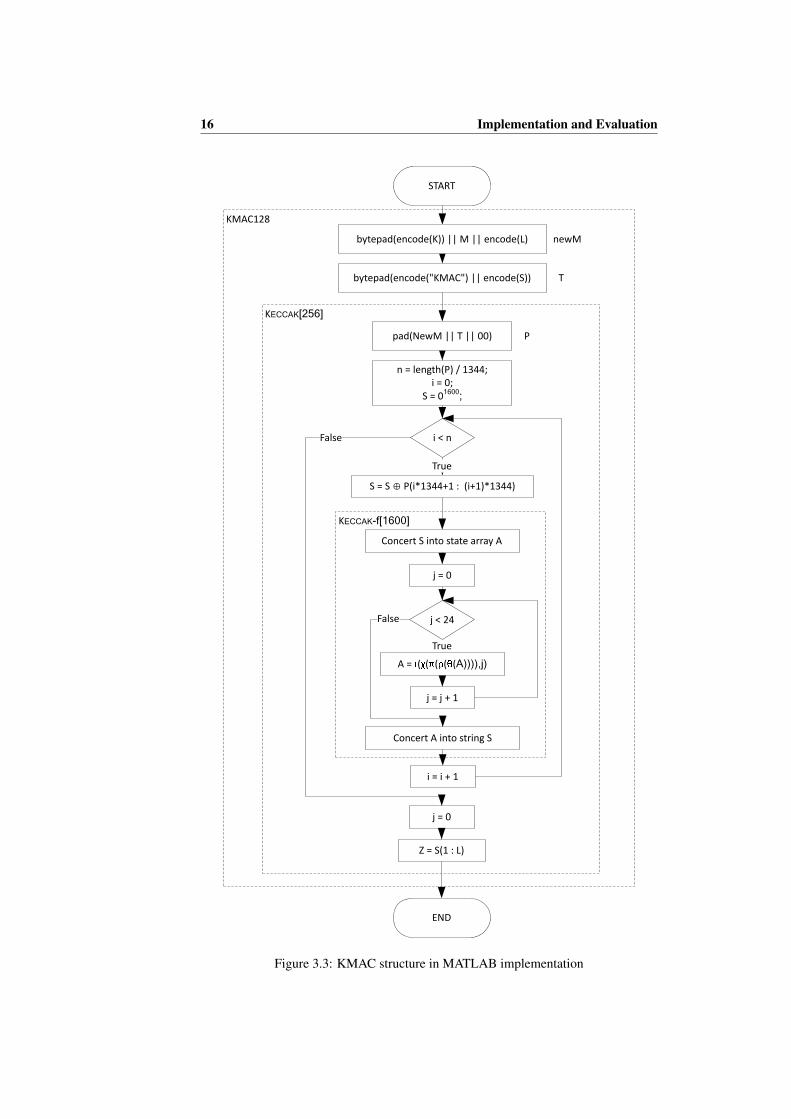
3.1.2 KMAC128 Implementation in MATLAB
In the definition, KMAC128 function follows a top-down structure. Correspondingto this, a bottom-up approach was adopted in the MATLAB implementation. Eachfunction from the bottom layer must be tested before building the up-layer functions.In addition, the KECCAK[256] function is validated with the test vectors provided by theKECCAK designers [12]. The flow chart illustrates the KMAC128 implementation inMATLAB shown in Figure 3.3.
16 Implementation and Evaluation
KMAC128
KECCAK[256]
KECCAK-f[1600]
START
bytepad(encode(K)) || M || encode(L) newM
bytepad(encode("KMAC") || encode(S)) T
i < n
n = length(P) / 1344;
i = 0;
S = 01600;
True
pad(NewM || T || 00) P
True
False
S = S ⊕ P(i*1344+1 : (i+1)*1344)
Concert S into state array A
Concert A into string S
j < 24
j = 0
A = �(�(�(�(�(A)))),j)
j = j + 1
i = i + 1
j = 0
False
Z = S(1 : L)
END
Figure 3.3: KMAC structure in MATLAB implementation

3.2 ASIC Design 17
There are two noteworthy things when it comes to KMAC128 implementation inMATLAB. The first one is the endianness of the processing bit strings. Not only theinput and the output string, but also the intermediate string could cause such problem.Take KECCAK[256] as an example, the order of the provided test vector inputs is aspecial format. There are two specific bit-reordering functions for the provided testinput, which can be found in the appendix of [1]. It would be mistaken if the inputsare used directly. Second, different build-in functions have restriction on the matrixdimension and the variable type in MATLAB. The description of functions should bechecked carefully before used.
3.2 ASIC Design
As mentioned before, a typical cell-based ASIC design flow is adopted in this project.This denotes that pre-designed logic cells, called standard cells, which are selecteddirectly from the standard-cell library, construct the outcome circuit. For this project,the software tools that are used in HDL design, functional simulation and logicsynthesis are Verilog HDL, ModelSim and Synopsys respectively. The synthesisresults are based on the 65-nanometer CMOS process technology provided by UMC65LL (Low Leakage).
3.2.1 Variable Specification
Unlike the MATLAB implementation, hardware description language (HDL) treatsvariables in fixed-point rather than floating-point. As a result, it is obligatory tospecify the length of input and output in ASIC design, likewise the intermediatevalues. The application area was taken into account when the lengths were specified.
In this section, only the specifications of input and output are revealed. The lengthof each input and output variable should be equivalent for both KMAC and C-CRC.Otherwise, it would be unfair to compare their performance under this condition.Moreover, the application area is also taken into account to produce a practical design.The specifications of the identical variables in both KMAC and C-CRC are shown inTable 3.1.
Length (bit)Data Transfer Width 128Input Message String 256, 512 or 1024
Secret Key (KMAC128) /Generator Polynomial Degree (C-CRC) 128
Customized String (KMAC128) /Encryption String (C-CRC) 128
Output String 128
Table 3.1: Specifications of the identical variables

18 Implementation and Evaluation
3.2.2 KMAC128 Implementation in HDL
To achieve an accurate and efficient implementation, a similar bottom-up approach isadopted in HDL as the one in MATLAB. On the basis of the algorithm structure inFigure 2.1, the KMAC128 implementation is divided into two main sections,including one section performs KECCAK - f [1600], and the other section that encryptsand controls the input and the round number of the first section.
According to the specification in Table 3.1, the maximum of input message lengthis 1024 bits. Consider the fact that the function bytepad(S,168) keep padding the inputstring until it can be divisible by 168 times 8, the output length should be an integermultiple of 1344. In our case, it should be 1344. Coincidentally, the first few steps ofKECCAK[256] achieve such a function of splitting the input after padding it to an integermultiple of 1344. Therefore, the input to the KECCAK[256] algorithm should be dividedinto three parts of the same length, newK, newS and newM. The adapted algorithm ispresented in Algorithm 3.1. The adapted KMAC128 algorithm is shown in Figure 3.4.
Algorithm 3.1 Adapted KMAC128(K,M,L,S)Input: K,M,L,SOutput: Z, len(Z) = len(L)
newK = bytepad(encode string(K),168)newS = bytepad(encode string(”KMAC”)‖encode string(S),168)newM = M ‖ right encode(L)‖00Z = KECCAK[256](newS‖newK ‖newM,L)
EncryptionKey
Message
newKey
newString
newMessage
Customized String
KECCAK-
f[1600] 24
KECCAK-
f[1600] 24KECCAK-
f[1600] 24
Figure 3.4: The adapted KMAC128 algorithm data flow diagram
On the basis of the adapted version of KMAC128, KECCAK[256] algorithm is alteredas Algorithm 3.2. Instead of spliting and pading, the inputs are used directly from theprevious algorithm. In this way, parallelism is able to take place while reading andprocessing. According to the test vector provided by the designer of KECCAK family, theproposed implementation of KECCAK[256] algorithm is validated through the KnownAnswer Test (KAT) provided by NIST.
3.2 ASIC Design 19
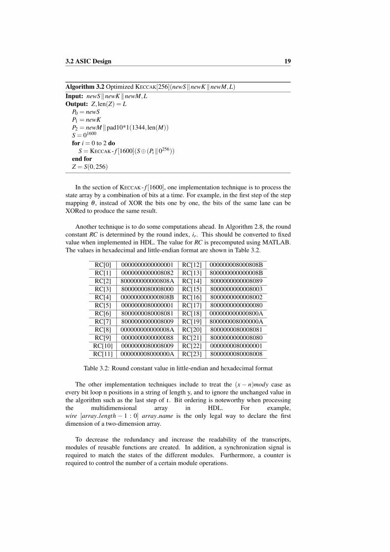
Algorithm 3.2 Optimized KECCAK[256](newS‖newK ‖newM,L)Input: newS‖newK ‖newM,LOutput: Z, len(Z) = L
P0 = newSP1 = newKP2 = newM ‖pad10*1(1344, len(M))S = 01600
for i = 0 to 2 doS = KECCAK - f [1600](S⊕(Pi ‖0256))
end forZ = S(0,256)
In the section of KECCAK - f [1600], one implementation technique is to process thestate array by a combination of bits at a time. For example, in the first step of the stepmapping θ , instead of XOR the bits one by one, the bits of the same lane can beXORed to produce the same result.
Another technique is to do some computations ahead. In Algorithm 2.8, the roundconstant RC is determined by the round index, ir. This should be converted to fixedvalue when implemented in HDL. The value for RC is precomputed using MATLAB.The values in hexadecimal and little-endian format are shown in Table 3.2.
RC[0] 0000000000000001 RC[12] 000000008000808BRC[1] 0000000000008082 RC[13] 800000000000008BRC[2] 800000000000808A RC[14] 8000000000008089RC[3] 8000000080008000 RC[15] 8000000000008003RC[4] 000000000000808B RC[16] 8000000000008002RC[5] 0000000080000001 RC[17] 8000000000000080RC[6] 8000000080008081 RC[18] 000000000000800ARC[7] 8000000000008009 RC[19] 800000008000000ARC[8] 000000000000008A RC[20] 8000000080008081RC[9] 0000000000000088 RC[21] 8000000000008080RC[10] 0000000080008009 RC[22] 0000000080000001RC[11] 000000008000000A RC[23] 8000000080008008
Table 3.2: Round constant value in little-endian and hexadecimal format
The other implementation techniques include to treat the (x− n)mody case asevery bit loop n positions in a string of length y, and to ignore the unchanged value inthe algorithm such as the last step of ι . Bit ordering is noteworthy when processingthe multidimensional array in HDL. For example,wire [array length− 1 : 0] array name is the only legal way to declare the firstdimension of a two-dimension array.
To decrease the redundancy and increase the readability of the transcripts,modules of reusable functions are created. In addition, a synchronization signal isrequired to match the states of the different modules. Furthermore, a counter isrequired to control the number of a certain module operations.

20 Implementation and Evaluation
In Table 3.1, the data transfer width is set to be 128. As a result, the input messageshould be separated and transmitted piece by piece. Accordingly, two input signals areadded to indicate the completeness of the input message, in valid and is last. Thein valid signal remains active until the end of the input. The is last signal turns toactive only when transferring the last piece of the input.
While reading the input message, the KECCAK - f [1600] computation for newKeyand newString can be processed at the same time. Therefore, the separation of readingdoes not delay the overall computation time. The complete HDL transcripts can befound in Appendix A.1.
3.2.3 C-CRC Implementation in HDL
In practice, the computation of CRC in hardware is realized by a linear-feedback shiftregister (LFSR). There are two types of LFSR, Fibonacci and Galois, shown inFigure 3.5. The reason why Galois, known as internal XORs LFSR, is chosen is that ithas shorter propagation delay and is more efficient to implement than the other one.
Q
QSET
CLR
S
R
1
Q
QSET
CLR
S
R
2
Feedback
Q
QSET
CLR
S
R
3
Q
QSET
CLR
S
R
4
Input Output
(a) Galois type LFSR
Q
QSET
CLR
S
R
1
Q
QSET
CLR
S
R
2
Feedback
Q
QSET
CLR
S
R
3
Q
QSET
CLR
S
R
4
Input
Output
(b) Fibonacci type LFSR
Figure 3.5: Two types of LFSR
Furthermore, the feedback part, which the value is connected to every XOR gate inLFSR, is selected to be XORed value from the input of the entire LFSR and the outputof the last shift register (shown in Figure 3.6). In this way, CRC computation is able tofinish within the shifts of the message bits number. As a result, the latency reduces thenumber of generator polynomial degree clock cycle.

3.2 ASIC Design 21
Q
QSET
CLR
S
R
1
Q
QSET
CLR
S
R
2
Feedback
Q
QSET
CLR
S
R
3
Q
QSET
CLR
S
R
4
Input
Output
Figure 3.6: The optimized Galois LFSR with less latency
In order to achieve the compatibility with any generator polynomial, the LFSRhere should be reconfigurable, or so-called programmable. A multiplexer (MUX) iscontroled by a bit of the generator polynomial to choose the input to the next shiftregister between the output of the previous register or the XORed value of the outputand the feedback (shown in Figure 3.7).
Generator Polynomial[1]
Q
QSET
CLR
S
R
1
S1
S2
D
C ENB
MUX1
Feedback
Figure 3.7: The programmable LFSR with any generator polynomial
Due to the property of LFSR, the input message is transmitted bit by bit.Therefore, a similar signal as in KMAC128, m valid, is required to indicate thevalidity of the input message. Instead of the signal is last, a new signal, pad valid, isrequired to indicate the completeness of the message and the beginning of theencryption string. These two signals are complementary to each other, which isrealized in the test-bench transcript.
When it comes to the end of input, there are two ways to implement the output of theLFSR. The illustration of C-CRC with two designs of the output shown in Figure 3.8.The first one is to read the checksum one bit per clock cycle. In this way, the outputof the last register is designed as the output of the LFSR. The CRC checksum will beread bit by bit as the input. The second implementation is to read all the output at thesame time, as soon as the computation is finished. The first design has the advantagein area, while the second design has the advantage in latency. The simulation results oftwo designs will be shown in Chapter 3.2.4.

22 Implementation and Evaluation
Message
Generator Polynomial[1]
Generator Polynomial[2]
Generator Polynomial[127]
Input Valid
Encryption String
OutputQ
QSET
CLR
S
R
1
S1
S2
D
C ENB
MUX1
Q
QSET
CLR
S
R
2
S1
S2
D
C ENB
MUX2
S1
S2
D
C ENB
MUX127
Q
QSET
CLR
S
R
128
CRC Output
Feedback
(a) LFSR produces output one bit per clock cycle
Message
Generator Polynomial[1]
Generator Polynomial[2]
Generator Polynomial[127]
Input Valid
Encryption String[1]
Output[128]
Q
QSET
CLR
S
R
1
S1
S2
D
C ENB
MUX1
Q
QSET
CLR
S
R
2
S1
S2
D
C ENB
MUX2
S1
S2
D
C ENB
MUX127
Q
QSET
CLR
S
R
128
CRC Output
Feedback
Encryption String[2]
Encryption String[128]
Output[2]
Output[1]
(b) LFSR produces all output in one clock cycle
Figure 3.8: C-CRC with two designs of the output section
3.2.4 Simulation Results and Analysis
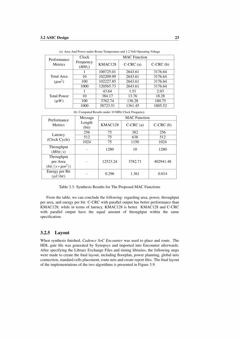
After implementing the two algorithms in ModelSim, the same test vector is used as theinput to the MATLAB implementation. The HDL implementation is validated since theoutput of the MATLAB version matches the HDL version. Next, the verified HDL codeis synthesized in Synopsys with UMC 65LL library and the specified working condition(25◦C temperature and 1.2 volt operating voltage). The results are shown in Table 3.3.
3.2 ASIC Design 23
(a) Area And Power under Room Temperature and 1.2 Volt Operating Voltage
PerformanceMetrics
ClockFrequency
(MHz)
MAC Function
KMAC128 C-CRC (a) C-CRC (b)
Total Area(µm2)
1 100725.01 2643.61 3176.6410 102209.99 2643.61 3176.64100 102227.85 2643.61 3176.64
1000 120565.73 2643.61 3176.64
Total Power(µW )
1 43.64 1.51 2.0310 384.17 13.76 18.28100 3762.74 136.28 180.75
1000 38723.51 1361.45 1805.52
(b) Computed Results under 10 MHz Clock Frequency
PerformanceMetrics
MessageLength
(bit)
MAC Function
KMAC128 C-CRC (a) C-CRC (b)
Latency(Clock Cycle)
256 75 382 256512 75 638 512
1024 75 1150 1024Throughput
(Mbit/s) - 1280 10 1280
Throughputper Area
(bit/(s∗µm2))- 12523.24 3782.71 402941.48
Energy per Bit(pJ/bit) - 0.296 1.361 0.014
Table 3.3: Synthesis Results for The Proposed MAC Functions
From the table, we can conclude the following: regarding area, power, throughputper area, and energy per bit: C-CRC with parallel output has better performance thanKMAC128; while in terms of latency, KMAC128 is better. KMAC128 and C-CRCwith parallel output have the equal amount of throughput within the samespecification.
3.2.5 LayoutWhen synthesis finished, Cadence SoC Encounter was used to place and route. TheHDL gate file was generated by Synopsys and imported into Encounter afterwards.After specifying the Library Exchange Files and timing libraries, the following stepswere made to create the final layout, including floorplan, power planning, global netsconnection, standard cells placement, route nets and create report files. The final layoutof the implementations of the two algorithms is presented in Figure 3.9.

24 Implementation and Evaluation
MAC function Total area of core (µm2)KMAC128 97113.204
C-CRC 2982.969
Table 3.4: Comparison of total area of core
(a) KMAC128
(b) C-CRC with parallel output
Figure 3.9: Layout of the implementations of KMAC128 and C-CRC

Chapter 4
Discussion and Conclusion
KMAC and C-CRC were designed and implemented within the same specification inChapter 3. Moreover, latency or power constraints were not taken into consideration.As a result, the comparison analysis was conditional and might vary for differentrequirements. In order to compare the two MAC functions in general, morespecifications and implementation with constraints are discussed in this chapter.
4.1 Implementation of Alternative Specification
In this thesis’s application area, i.e. embedded devices, the length of secret key andencryption string will not affect the performance without considering transmissiontime. As mentioned above, pre-computation and transmission is possible to conduct atthe same time. Therefore, the length of input message is the most important factor inthe specification.
For C-CRC, the HDL code for algorithm will not change since it is independent ofthe input message length. The latency depends on both the output and input messagelength (len(M)+L).
For KMAC, the algorithm was adapted in Figure 3.4 in the specification ofTable 3.1. If the length of input message increased to more than1343− 16− 2− 2 = 1323 bits and other input length stays the same, KECCAK[256]will be called more than 3 times depending on r = 2+(len(M)+ 16+ 2+ 2)/1343.The latency will increase to 25∗ r. On the other hand, the total area will not increase alot due to the unchanged core function. The KMAC128 implementation of more than1323 input message bits is illustrated as the sequence diagram in Figure 4.1.

26 Discussion and Conclusion
KMAC128 KECCAK -f [1600]
newKey
newString
f-acknowledge
f-acknowledge
24 clock cycle
1 clock cycle
24 clock cycle
1 clock cyclenewMessage[1]
f-acknowledge
24 clock cycle
1 clock cycle
newMessage[2]
f-acknowledge
24 clock cycle
1 clock cycle
Figure 4.1: The sequence diagram of KMAC128 with a longer input message
4.2 Implementation of Special Constraints
Essentially, ”latency or power constraints” is another way of performing designtrade-off. For example, when the implementation places a higher priority on latency, itmeans that area and other performance metrics can be sacrificed in order to decreaselatency. In this chapter, only constraints that cannot be satisfied by the implementationof Chapter 3 is discussed.
4.2.1 Latency Constraint
Parallelism is one technique to decrease latency for both of the MAC functions. Loopunrolling and data parallel processing are two common way to achieve parallelism.For KMAC, we can increase the round instance in one clock cycle (illustrated inFigure 4.2). For C-CRC, we can process two message at the same time. With otherspecification unchanged, comparison between the results of parallelism of two andserial are shown in Table 4.1.

4.2 Implementation of Special Constraints 27
EncryptionKey
Message
newKey
newString
newMessage
Customized String
KECCAK-
f[1600]
12
KECCAK-
f[1600]
KECCAK-
f[1600]
12
KECCAK-
f[1600]
KECCAK-
f[1600]
12
KECCAK-
f[1600]
Figure 4.2: The data flow diagram of KMAC with round instance of two
PerformanceMetrics
KMAC128(round
instance:1)
KMAC(round
instance:2)
C-CRC (b)(parallelism:1)
C-CRC (b)(parallelism:2)
Total Area (µm2) 102209.99 129448.28 3176.64 6353.28
Total Power(µW ) 384.17 447.17 18.28 36.55
Latency 75 39 1024 1024Throughput
(Mbit/s) 1280 1280 1280 2560
Throughputper Area
(bit/(s∗µm2))12523.24 9888.12 402941.48 402941.48
Energy per Bit(pJ/bit) 0.296 0.343 0.014 0.014
Table 4.1: Comparison in 1024 bits message length and 10MHz Clock Frequency

28 Discussion and Conclusion
From the results we can see that, KMAC128 is influenced by parallelism less thanC-CRC in area, power and throughput. In latency, throughput per area and energy perbit, C-CRC stays the same. For parallelism of more than two, similar result can beconcluded. For comparison between KMAC128 and C-CRC, similar conclusions canbe drawn as in Chapter 3.2.4.
4.2.2 Power ConstraintPower gating is a common technique to decrease power consumption in ASIC design,for instance in LFSR of CRC computation. The concept is to shut off the ”useless”gate when not needed, and leakage power is reduced consequently. This technique canbe illustrated in Figure 4.3. Unfortunately, in the applied technology library, there is nosingle CMOS gate that can be directly used in HDL code. Therefore, a multiplexer willbe replaced to act as the switch of controlled gates, which consumes more power thansingle CMOS gate. Moreover, the implementations with this design fails the criticalpath timing analysis when the clock frequency is more than 10MHz. For C-CRC, theleakage power can be ignored compared to dynamic power. As a result, power gatingis not suitable for both KMAC and C-CRC.
Generator Polynomial[1]
Input Valid
Q
QSET
CLR
S
R
1
S1
S2
D
C ENB
MUX1
Feedback
Figure 4.3: Power gating in LFSR of C-CRC
4.3 ConclusionFor KMAC128, latency is the outstanding merit as well as its security strengths. In theaspect of embedded devices, security strength is not the primary goal. AlthoughKMAC128’s latency increases when input message length increases, it still has lowergrowth rate compared to C-CRC. KMAC128’s latency performance can be improvedby increasing the number of round instances computed in one clock cycle. However,this improvement has a limit where no more permutation can be performed in oneclock cycle.
For C-CRC, it achieves excellent performance in terms of area and power. Withinthe domain of C-CRC, the implementation with parallel output offers much higherthroughput at the cost of a trivial increase in area and power consumption. Thus, it hasthe similar result in throughput per area and energy per bit. Latency is the only bottle

4.4 Future Work 29
neck for C-CRC due to the feature of LFSR. Little improvement in this thesis hasbeen made to decrease latency, including parallel output.
4.4 Future WorkFor both of the implementations, there is still work left to do after floor planning androute. Time and power analysis should be performed to verify the circuit.Additionally, functional verification should be executed on the gate level net-list.When finishing physical synthesis, more accurate power consumption result should bepresented. And the throughput and latency might be affected by the propagation delay.
Since the latency is the only bottleneck for C-CRC, more effort could be put intooptimizing the algorithm or the CRC computation. Also, how to extract entropy froma longer length output would be an interesting topic to investigate.
Bibliography
[1] National Institute of Standards and Technology, FIPS PUB 202: SHA-3 Standard: Permutation-Based Hash and Extendable-Output Functions.Gaithersburg, MD 20899-8900: National Institute of Standards and Technology,Aug. 2015. [Online]. Available: http://nvlpubs.nist.gov/nistpubs/FIPS/NIST.FIPS.202.pdf
[2] Alfred J. Menezes, Handbook of applied cryptography, ser. The CRC Press serieson discrete mathematics and its applications. Boca Raton: CRC, 1997.
[3] M. Bellare, R. Canetti, and H. Krawczyk, “Keying hash functions for messageauthentication.” Springer-Verlag, 1996, pp. 1–15.
[4] National Institute of Standards and Technology, FIPS PUB 198-1: The Keyed-Hash Message Authentication Code (HMAC). Gaithersburg, MD 20899-8900:National Institute of Standards and Technology, Jul. 2008. [Online]. Available:http://nvlpubs.nist.gov/nistpubs/FIPS/NIST.FIPS.198-1.pdf
[5] M. Stevens, “Fast collision attack on md5.” IACR Cryptology ePrint Archive,vol. 2006, p. 104, 2006. [Online]. Available: http://dblp.uni-trier.de/db/journals/iacr/iacr2006.html#Stevens06
[6] M. Stevens, E. Bursztein, P. Karpman, A. Albertini, and Y. Markov, “The firstcollision for full sha-1,” Cryptology ePrint Archive, Report 2017/190, 2017, http://eprint.iacr.org/2017/190.
[7] G. Bertoni, J. Daemen, M. Peeters, and G. Van Assche, “The Making ofKECCAK,” Cryptologia, vol. 38, no. 1, p. 26, 2014.
[8] John Kelsey, Shu-jen Chang, and Ray Perlner, NIST Special Publication800-185: SHA-3 Derived Functions: cSHAKE, KMAC, TupleHash andParallelHash. Gaithersburg, MD 20899-8930: National Institute of Standardsand Technology, Dec. 2016. [Online]. Available: http://nvlpubs.nist.gov/nistpubs/SpecialPublications/NIST.SP.800-185.pdf
[9] W. Peterson and D. Brown, “Cyclic codes for error detection,” Proceedings of theIRE, vol. 49, no. 1, pp. 228–235, January 1961.
[10] E. Dubrova, M. Naslund, G. Selander, and F. Lindqvist, “Message authenticationbased on cryptographically secure crc without polynomial irreducibility test,”Cryptography and Communications, pp. 1–17, 2017. [Online]. Available:http://dx.doi.org/10.1007/s12095-017-0227-8

BIBLIOGRAPHY 31
[11] UMC, “UMK65lscllmvbbr b UMC 65nm Low-K Multi-Voltage Low LeakageRVT Tapless Standard Cell Library Databook,” Nov. 2011.
[12] “KeccakCodePackage.” [Online]. Available: https://github.com/gvanas/KeccakCodePackage

Appendix A
Verilog HDL Transcript
A.1 KMACFile name: kmac128.v
module kmac128 #
(
parameter Key_Length = 128,
parameter Output_Length = Key_Length
)
(
input wire clk,
input wire reset,
input wire [0:127] in_X,
input wire in_ready,
input wire is_last,
input wire [0:Key_Length-1] in_K,
input wire [0:127] in_S,
output wire [0:Output_Length-1] out,
output wire out_ready
);
//bytepad Key = left_encode(168) || left_encode(128) || K || 0
wire [0:1343] new_K;
assign new_K = {16’b1000000000010101,
16’b1000000000000001, in_K, 1184’b0};
genvar gv_B, gv_b;
//generate in_S in big endian order
wire [0:127] S_bigen;
generate
for(gv_B=0; gv_B<128/8; gv_B=gv_B+1)
begin : S_1
for(gv_b=0; gv_b<8; gv_b=gv_b+1)
begin : S_2
assign S_bigen[gv_B*8+gv_b] = in_S[gv_B*8+(7-gv_b)];

A.1 KMAC 33
end
end
endgenerate
//bytepad customized String and "KMAC" = left_encode(168)
//|| left_encode(128) || S || left_encode(32) || "KMAC" || 0
wire [0:1343] new_S;
assign new_S = {16’b1000000000010101, 16’b1000000000000100,
32’b11010010101100101000001011000010, 16’b1000000000000001,
S_bigen, 1136’b0};
//read message and pad after finish reading
reg [0:7] read_count;
reg [0:1343] X_array;
always @(posedge clk)
if (reset)
begin
X_array = 0;
read_count = 0;
end
else
begin
if (in_ready)
begin
X_array = {X_array[128:1343], in_X};
read_count = {read_count[1:7], 1’b1};
end
if (is_last)
begin
case (read_count)
//new_X = X || right_encode(Output_Length) || 00
8’b00000011: X_array = {X_array[1088:1343],
16’b0000000110000000, 2’b0, 1’b1,1068’b0, 1’b1};
8’b00001111: X_array = {X_array[832:1343],
16’b0000000110000000, 2’b0, 1’b1,812’b0, 1’b1};
8’b11111111: X_array = {X_array[320:1343],
16’b0000000110000000, 2’b0, 1’b1,300’b0, 1’b1};
endcase
end
end
wire f_ack;
wire f_out_ready;
//only the first part of message or the previous output
//of permutation ready, f_in_ready = 1
reg f_in_ready;
always @(posedge clk)
if (reset)
f_in_ready = 0;

34 Verilog HDL Transcript
else
begin
if ((in_ready && !read_count[6]) || f_out_ready)
f_in_ready = 1;
if (f_in_ready)
f_in_ready = !f_ack;
end
reg [0:2] f_count;
always @(posedge clk)
if (reset)
f_count = 0;
else
if (f_out_ready && f_in_ready)
f_count = {1’b1, f_count[0:1]};
wire [0:1343] f_in;
wire [0:1599] f_out;
assign f_in = (!f_count[0]) ? new_S : (!f_count[1]) ?
new_K : (!f_count[2]) ? X_array : 0;
f_permutation f_permutation_ (clk, reset, f_in, f_in_ready,
f_ack, f_out, f_out_ready);
assign out_ready = f_count[2];
assign out = out_ready ? f_out[0:Output_Length-1] : 0;
endmodule

A.1 KMAC 35
File name: f permutation.v
module f_permutation
(
input clk, reset,
input [0:1343] in,
input in_ready,
output ack,
output reg [0:1599] out,
output reg out_ready
);
reg [0:22] i; /* select round constant */
wire [0:1599] round_in, round_out;
wire [0:63] rc;
wire update;
wire accept;
reg calc; /* == 1: calculating rounds */
assign accept = in_ready && !calc; // in_ready & (i == 0)
always @ (posedge clk)
if (reset) i <= 0;
else i <= {accept, i[0:21]};
always @ (posedge clk)
if (reset) calc <= 0;
else calc <= (calc & (~ i[22])) | accept;
assign update = calc | accept;
assign ack = accept;
always @ (posedge clk)
if (reset)
out_ready <= 0;
else if (accept)
out_ready <= 0;
else if (i[22]) // only change at the last round
out_ready <= 1;
assign round_in = accept ? {in ^ out[0:1343],
out[1344:1599]} : out;
rconst rconst_ ({accept, i}, rc);
round round_ (round_in, rc, round_out);
always @ (posedge clk)

36 Verilog HDL Transcript
if (reset)
out <= 0;
else if (update)
out <= round_out;
endmodule
File name: rconst.v
module rconst(i, rc);
input wire [0:23] i;
output reg [0:63] rc;
always @ (i)
begin
rc = 0;
rc[0] = i[0] | i[4] | i[5] | i[6] | i[7] |
i[10] | i[12] | i[13] | i[14] | i[15] | i[20] | i[22];
rc[1] = i[1] | i[2] | i[4] | i[8] | i[11] |
i[12] | i[13] | i[15] | i[16] | i[18] | i[19];
rc[3] = i[2] | i[4] | i[7] | i[8] | i[9] | i[10] |
i[11] | i[12] | i[13] | i[14] | i[18] | i[19] | i[23];
rc[7] = i[1] | i[2] | i[4] | i[6] | i[8] | i[9] |
i[12] | i[13] | i[14] | i[17] | i[20] | i[21];
rc[15] = i[1] | i[2] | i[3] | i[4] | i[6] | i[7] | i[10] |
i[12] | i[14] | i[15] | i[16] | i[18] | i[20] | i[21] | i[23];
rc[31] = i[3] | i[5] | i[6] | i[10] | i[11] |
i[12] | i[19] | i[20] | i[22] | i[23];
rc[63] = i[2] | i[3] | i[6] | i[7] | i[13] |
i[14] | i[15] | i[16] | i[17] | i[19] | i[20] | i[21] | i[23];
end
endmodule
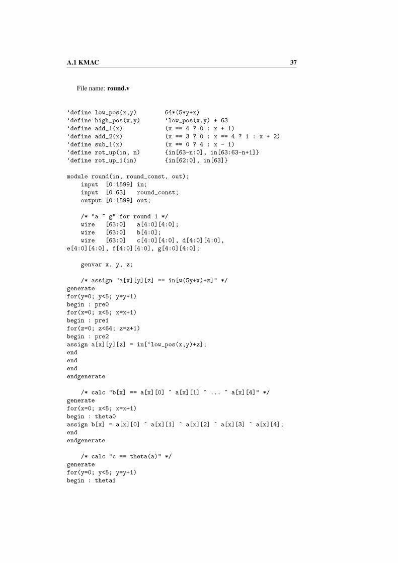
A.1 KMAC 37
File name: round.v
‘define low_pos(x,y) 64*(5*y+x)
‘define high_pos(x,y) ‘low_pos(x,y) + 63
‘define add_1(x) (x == 4 ? 0 : x + 1)
‘define add_2(x) (x == 3 ? 0 : x == 4 ? 1 : x + 2)
‘define sub_1(x) (x == 0 ? 4 : x - 1)
‘define rot_up(in, n) {in[63-n:0], in[63:63-n+1]}
‘define rot_up_1(in) {in[62:0], in[63]}
module round(in, round_const, out);
input [0:1599] in;
input [0:63] round_const;
output [0:1599] out;
/* "a ~ g" for round 1 */
wire [63:0] a[4:0][4:0];
wire [63:0] b[4:0];
wire [63:0] c[4:0][4:0], d[4:0][4:0],
e[4:0][4:0], f[4:0][4:0], g[4:0][4:0];
genvar x, y, z;
/* assign "a[x][y][z] == in[w(5y+x)+z]" */
generate
for(y=0; y<5; y=y+1)
begin : pre0
for(x=0; x<5; x=x+1)
begin : pre1
for(z=0; z<64; z=z+1)
begin : pre2
assign a[x][y][z] = in[‘low_pos(x,y)+z];
end
end
end
endgenerate
/* calc "b[x] == a[x][0] ^ a[x][1] ^ ... ^ a[x][4]" */
generate
for(x=0; x<5; x=x+1)
begin : theta0
assign b[x] = a[x][0] ^ a[x][1] ^ a[x][2] ^ a[x][3] ^ a[x][4];
end
endgenerate
/* calc "c == theta(a)" */
generate
for(y=0; y<5; y=y+1)
begin : theta1
38 Verilog HDL Transcript
for(x=0; x<5; x=x+1)
begin : theta2
assign c[x][y] = a[x][y] ^ (b[‘sub_1(x)] ^ ‘rot_up_1(b[‘add_1(x)]));
end
end
endgenerate
/* calc "d == rho(c)" */
assign d[0][0] = c[0][0];
assign d[1][0] = ‘rot_up_1(c[1][0]);
assign d[2][0] = ‘rot_up(c[2][0], 62);
assign d[3][0] = ‘rot_up(c[3][0], 28);
assign d[4][0] = ‘rot_up(c[4][0], 27);
assign d[0][1] = ‘rot_up(c[0][1], 36);
assign d[1][1] = ‘rot_up(c[1][1], 44);
assign d[2][1] = ‘rot_up(c[2][1], 6);
assign d[3][1] = ‘rot_up(c[3][1], 55);
assign d[4][1] = ‘rot_up(c[4][1], 20);
assign d[0][2] = ‘rot_up(c[0][2], 3);
assign d[1][2] = ‘rot_up(c[1][2], 10);
assign d[2][2] = ‘rot_up(c[2][2], 43);
assign d[3][2] = ‘rot_up(c[3][2], 25);
assign d[4][2] = ‘rot_up(c[4][2], 39);
assign d[0][3] = ‘rot_up(c[0][3], 41);
assign d[1][3] = ‘rot_up(c[1][3], 45);
assign d[2][3] = ‘rot_up(c[2][3], 15);
assign d[3][3] = ‘rot_up(c[3][3], 21);
assign d[4][3] = ‘rot_up(c[4][3], 8);
assign d[0][4] = ‘rot_up(c[0][4], 18);
assign d[1][4] = ‘rot_up(c[1][4], 2);
assign d[2][4] = ‘rot_up(c[2][4], 61);
assign d[3][4] = ‘rot_up(c[3][4], 56);
assign d[4][4] = ‘rot_up(c[4][4], 14);
/* calc "e == pi(d)" */
assign e[0][0] = d[0][0];
assign e[0][2] = d[1][0];
assign e[0][4] = d[2][0];
assign e[0][1] = d[3][0];
assign e[0][3] = d[4][0];
assign e[1][3] = d[0][1];
assign e[1][0] = d[1][1];
assign e[1][2] = d[2][1];
assign e[1][4] = d[3][1];
assign e[1][1] = d[4][1];
assign e[2][1] = d[0][2];
assign e[2][3] = d[1][2];
assign e[2][0] = d[2][2];
assign e[2][2] = d[3][2];
assign e[2][4] = d[4][2];

A.1 KMAC 39
assign e[3][4] = d[0][3];
assign e[3][1] = d[1][3];
assign e[3][3] = d[2][3];
assign e[3][0] = d[3][3];
assign e[3][2] = d[4][3];
assign e[4][2] = d[0][4];
assign e[4][4] = d[1][4];
assign e[4][1] = d[2][4];
assign e[4][3] = d[3][4];
assign e[4][0] = d[4][4];
/* calc "f = chi(e)" */
generate
for(y=0; y<5; y=y+1)
begin : chi0
for(x=0; x<5; x=x+1)
begin : chi1
assign f[x][y] = e[x][y] ^ ((~ e[‘add_1(x)][y]) & e[‘add_2(x)][y]);
end
end
endgenerate
/* calc "g = iota(f)" */
generate
for(z=0; z<64; z=z+1)
begin : iota0
if(z==0 || z==1 || z==3 || z==7 || z==15 || z==31 || z==63)
assign g[0][0][z] = f[0][0][z] ^ round_const[z];
else
assign g[0][0][z] = f[0][0][z];
end
endgenerate
generate
for(y=0; y<5; y=y+1)
begin : iota1
for(x=0; x<5; x=x+1)
begin : iota2
if(x!=0 || y!=0)
assign g[x][y] = f[x][y];
end
end
endgenerate
/* assign "out[w(5y+x)+z] == out_var[x][y][z]" */
generate
for(y=0; y<5; y=y+1)
begin : post0
for(x=0; x<5; x=x+1)
begin : post1

40 Verilog HDL Transcript
for(z=0; z<64; z=z+1)
begin : post2
assign out[‘low_pos(x,y)+z] = g[x][y][z];
end
end
end
endgenerate
endmodule
‘undef low_pos
‘undef high_pos
‘undef add_1
‘undef add_2
‘undef sub_1
‘undef rot_up
‘undef rot_up_1

A.1 KMAC 41
File name: testbench kmac128.v
‘timescale 1ns / 1ps
‘define P 20
module test_kmac128;
// Inputs
reg clk;
reg reset;
reg [0:127] in_X;
reg in_ready;
reg is_last;
reg [0:127] in_K;
reg [0:127] in_S;
// Outputs
wire [0:127] out;
wire out_ready;
// Var
integer i;
// Instantiate the Unit Under Test (UUT)
kmac128 uut (
.clk(clk),
.reset(reset),
.in_X(in_X),
.in_ready(in_ready),
.is_last(is_last),
.in_K(in_K),
.in_S(in_S),
.out(out),
.out_ready(out_ready)
);
initial begin
// Initialize Inputs
clk = 0;
reset = 0;
in_X = 0;
in_ready = 0;
is_last = 0;
in_K = 0;
in_S = 0;
// Wait 100 ns for global reset to finish
#50;
in_K = 128’h52A608AB21CCDD8A4457A57EDE782176;

42 Verilog HDL Transcript
in_S = "The test message";
#50;
// Add stimulus here
@ (negedge clk);
reset = 1; #(‘P*4); reset = 0;
in_ready = 1;
in_X = 128’h9F2FCC7C90DE090D6B87CD7E9718C1EA; #(‘P);
in_X = 128’h6CB21118FC2D5DE9F97E5DB6AC1E9C10;
is_last = 1; #(‘P);
in_ready = 0; is_last = 0;
while (out_ready !== 1)
#(‘P);
check(128’h0661EBA1FE4D68A099EA222AB2854C20);
reset = 1; #(‘P*4); reset = 0;
in_ready = 1; is_last = 0;
in_X = 128’hE926AE8B0AF6E53176DBFFCC2A6B88C6; #(‘P);
in_X = 128’hBD765F939D3D178A9BDE9EF3AA131C61; #(‘P);
in_X = 128’hE31C1E42CDFAF4B4DCDE579A37E150EF; #(‘P);
in_X = 128’hBEF5555B4C1CB40439D835A724E2FAE7;
is_last = 1; #(‘P);
in_ready = 0; is_last = 0;
while (out_ready !== 1)
#(‘P);
check(128’h00459CE25CA61F87020D1AF65CEBBB8E);
reset = 1; #(‘P*4); reset = 0;
in_ready = 1; is_last = 0;
in_X = 128’h2B6DB7CED8665EBE9DEB080295218426; #(‘P);
in_X = 128’hBDAA7C6DA9ADD2088932CDFFBAA1C141; #(‘P);
in_X = 128’h29BCCDD70F369EFB149285858D2B1D15; #(‘P);
in_X = 128’h5D14DE2FDB680A8B027284055182A0CA; #(‘P);
in_X = 128’hE275234CC9C92863C1B4AB66F304CF06; #(‘P);
in_X = 128’h21CD54565F5BFF461D3B461BD40DF281; #(‘P);
in_X = 128’h98E3732501B4860EADD503D26D6E6933; #(‘P);
in_X = 128’h8F4E0456E9E9BAF3D827AE685FB1D817;
is_last = 1; #(‘P);
in_ready = 0; is_last = 0;
while (out_ready !== 1)
#(‘P);
check(128’h5E9C40703AEF6D7019A947CF92DF320E);
$display("Good!");
$finish;
end
always #(‘P/2) clk = ~ clk;

A.1 KMAC 43
task error;
begin
$display("E");
$finish;
end
endtask
task check;
input [0:127] wish;
begin
if (out !== wish)
begin
$display("%h %h", out, wish); error;
end
end
endtask
endmodule
‘undef P

44 Verilog HDL Transcript
A.2 C-CRC with parallel output
File name: s crc.v
module s_crc #
(
// degree of generator polynomial
parameter Gen_Degree = 128,
// length of CRC/LFSR output
parameter Output_Length = Gen_Degree
)
(
input wire clk,
//clock signal
input wire in_valid,
//input valid signal for valid input
input wire m_in,
//plain text input message bit by bit in big endian order
input wire [Gen_Degree-1:1] gen_polynomial,
//generator polynomial without LS and MS bits
input wire out_valid,
//output valid sinal for valid output
input wire [Gen_Degree-1:0] pad,
//pad s produced by stream cipher bit by bit
output wire [Gen_Degree-1:0] e_out
//encrypted output
);
wire [Gen_Degree-1:0] ff_state;
//current state(output) of each flipflop
assign e_out = ff_state ^ pad;
wire rst;
//reset signal to each flipflop
//initialize flipflop to all 0’s when no input or no output
assign rst = in_valid || out_valid;
wire feedback;
//feedback wire
assign feedback = m_in ^ ff_state[Output_Length-1];
wire [Gen_Degree-1:1] ori_input;
assign ori_input = {ff_state[Gen_Degree-2:0]};
//original input of each multiplexer is the output of the front flipflop
wire [Gen_Degree-1:1] xor_input;
assign xor_input = ori_input ^ {Gen_Degree-1{feedback}};
wire [Gen_Degree-1:1] xor_enable;
//multiplexer select signal

A.2 C-CRC with parallel output 45
assign xor_enable = gen_polynomial[Gen_Degree-1:1]
& {Gen_Degree-1{in_valid}};
wire [Gen_Degree-1:1] mux_out;
mux M1[Gen_Degree-1:1] (mux_out, xor_enable, xor_input, ori_input);
/*
,----------+------------+-------------------------+------------.
| | | | |
| .----. V .----. V .----. .----. V .----. |
‘->| 0 |-(+)->| 1 |->(+)->| 2 |->...->|n-2 |->(+)->| n-1|->(+)<-DIN (MSB first)
’----’ ’----’ ’----’ ’----’ ’----’
*/
flipflop F1[Gen_Degree-1:0] (ff_state, clk, rst,
{mux_out[Gen_Degree-1:1], feedback});
endmodule
File name: mux.v
/*
* multiplexer to enable xor between each FF
*/
module mux(mux_out, mux_select, a_input, b_input);
input wire mux_select, a_input, b_input;
output wire mux_out;
assign mux_out = (mux_select) ? a_input : b_input;
endmodule
File name: flipflop.v
module flipflop(q, clk, rst, d);
input clk, rst, d;
output reg q;
always @(posedge clk)
begin
if (!rst)
q <= 1’b0;
else
q <= d;
end
endmodule

46 Verilog HDL Transcript
File name: testbench scrc.v
‘timescale 1ns / 1ps
‘define P 20
module s_crc_tb();
// Inputs
reg clk;
reg m_in;
reg [127:1] gen_polynomial;
reg in_valid;
reg out_valid;
reg [0:255] message_1;
reg [0:511] message_2;
reg [0:1023] message_3;
reg [127:0] pad;
// Outputs
wire [127:0] e_out;
// Var
integer i;
// Instantiate the Unit Under Test (UUT)
s_crc utt (
.clk(clk),
.in_valid(in_valid),
.m_in(m_in),
.gen_polynomial(gen_polynomial),
.out_valid(out_valid),
.pad(pad),
.e_out(e_out)
);
initial begin
// Initialize Inputs
clk = 0;
in_valid = 0;
out_valid = 0;
gen_polynomial = 0;
m_in = 0;
pad = 0;
// Wait 100 ns for global reset to finish
#50;
gen_polynomial = 127’h9F2FCC7C90DE090D6B87CD7E9718C1E;
message_1 = 256’h9F2FCC7C90DE090D6B87CD7E9718C1EA6CB2
1118FC2D5DE9F97E5DB6AC1E9C10;

A.2 C-CRC with parallel output 47
message_2 = 512’hE926AE8B0AF6E53176DBFFCC2A6B88C6BD76
5F939D3D178A9BDE9EF3AA131C61E31C1E42CDFA
F4B4DCDE579A37E150EFBEF5555B4C1CB40439D835A724E2FAE7;
message_3 = 1024’h2B6DB7CED8665EBE9DEB080295218426BDA
A7C6DA9ADD2088932CDFFBAA1C14129BCCDD70F3
69EFB149285858D2B1D155D14DE2FDB680A8B027284055182A0C
AE275234CC9C92863C1B4AB66F304CF0621CD54565F5BFF461D3B461
BD40DF28198E3732501B4860EADD503D26D6E69338F4E0456E9E9BAF3D827AE685FB1D817;
pad = 128’h9F2FCC7C90DE090D6B87CD7E9718C1EA;
#50;
// Add stimulus here
@ (negedge clk);
in_valid = 1;
for (i = 0; i < 255; i = i + 1)
begin
m_in = message_1[i]; #(‘P);
end
m_in = message_1[255]; #(‘P);
in_valid = 0;
out_valid = 1; #(‘P);
out_valid = 0; #(‘P);
//check
@ (negedge clk);
in_valid = 1;
for (i = 0; i < 511; i = i + 1)
begin
m_in = message_2[i]; #(‘P);
end
m_in = message_2[511]; #(‘P);
in_valid = 0;
out_valid = 1; #(‘P);
out_valid = 0; #(‘P);
//check
@ (negedge clk);
in_valid = 1;
for (i = 0; i < 1023; i = i + 1)
begin
m_in = message_3[i]; #(‘P);
end
m_in = message_3[1023]; #(‘P);
in_valid = 0;

48 Verilog HDL Transcript
out_valid = 1; #(‘P);
out_valid = 0; #(‘P);
//check
$display("Good!");
$finish;
end
always #(‘P/2) clk = ~ clk;
task error;
begin
$display("E");
$finish;
end
endtask
task check;
input [127:0] wish;
begin
if (e_out !== wish)
begin
$display("%h %h", e_out, wish); error;
end
end
endtask
endmodule
‘undef P

TRITA TRITA-ICT-EX-2017:51
www.kth.se