Evaluation of Comprehensive Seismic Design of Bridges ... · PDF fileFINAL REPORT Evaluation...
513
FINAL REPORT Evaluation of Comprehensive Seismic Design of Bridges (LRFD) in Illinois Project IA-H2, FY 02 Report No. ITRC FR 02-3 Prepared by Nader Panahshahi W. Bradford Cross and Nima Arjomandnia Bardia Emami Joshua Biller Gennadiy Ivanov Shikhar Shrestha Amir Arab Department of Civil Engineering Southern Illinois University Edwardsville Edwardsville, Illinois Sanjeev Kumar Department of Civil Engineering Southern Illinois University Carbondale Ward Nicholas Marianos, Jr. Modjeski & Masters, Inc. Edwardsville, Illinois Shahram Pezeshk The University of Memphis Memphis, Tennessee June 2004 Illinois Transportation Research Center Illinois Department of Transportation
-
Upload
phungkhuong -
Category
Documents
-
view
216 -
download
2
Transcript of Evaluation of Comprehensive Seismic Design of Bridges ... · PDF fileFINAL REPORT Evaluation...

FINAL REPORT
Evaluation of Comprehensive Seismic Design of Bridges (LRFD) in Illinois
Project IA-H2, FY 02
Report No. ITRC FR 02-3
Prepared by
Nader Panahshahi W. Bradford Cross
and Nima Arjomandnia
Bardia Emami Joshua Biller
Gennadiy Ivanov Shikhar Shrestha
Amir Arab Department of Civil Engineering
Southern Illinois University Edwardsville Edwardsville, Illinois
Sanjeev Kumar
Department of Civil Engineering Southern Illinois University Carbondale
Ward Nicholas Marianos, Jr.
Modjeski & Masters, Inc. Edwardsville, Illinois
Shahram Pezeshk
The University of Memphis Memphis, Tennessee
June 2004
Illinois Transportation Research Center Illinois Department of Transportation

ILLINOIS TRANSPORTATION RESEARCH CENTER
This research project was sponsored by the State of Illinois, acting by and through its Department of Transportation, according to the terms of the Memorandum of Understanding established with the Illinois Transportation Research Center. The Illinois Transportation Research Center is a joint Public-Private-University cooperative transportation research unit underwritten by the Illinois Department of Transportation. The purpose of the Center is the conduct of research in all modes of transportation to provide the knowledge and technology base to improve the capacity to meet the present and future mobility needs of individuals, industry and commerce of the State of Illinois. Research reports are published throughout the year as research projects are completed. The contents of these reports reflect the views of the authors who are responsible for the facts and the accuracy of the data presented herein. The contents do not necessarily reflect the official views or policies of the Illinois Transportation Research Center or the Illinois Department of Transportation. This report does not constitute a standard, specification, or regulation. Neither the United States Government nor the State of Illinois endorses products or manufacturers. Trade or manufacturers’ names appear in the reports solely because they are considered essential to the object of the reports.
Illinois Transportation Research Center Members
Bradley University DePaul University
Eastern Illinois University Illinois Department of Transportation
Illinois Institute of Technology Northern Illinois University
Northwestern University Southern Illinois University Carbondale
Southern Illinois University Edwardsville University of Illinois at Chicago
University of Illinois at Springfield University of Illinois at Urbana-Champaign
Western Illinois University
Reports may be obtained by writing to the administrative offices of the Illinois Transportation Research Center at Southern Illinois University Edwardsville, Campus Box 1803, Edwardsville, IL 62026-1803 (telephone 618-650-2972), or you may contact the Engineer of Physical Research, Illinois Department of Transportation, at 217-782-6732.

Technical Report Documentation Page
1. Report No.
ITRC FR 02-3
2. Government Accession No. 3. Recipient’s Catalog No.
5. Report Date June 2004
4. Title and Subtitle
Evaluation of Comprehensive Seismic Design of Bridges (LRFD) in Illinois 6. Performing Organization Code
8. Performing Organization Report No. 7. Author(s) Southern Illinois University Edwardsville-Nader Panahshahi, W. Bradford Cross,Nima Arjomandnia, Bardia Emami, Joshua Biller, Gennadiy Ivanov, Shikhar Shrestha, Amir Arab Southern Illinois University Carbondale – Sanjeev Kumar Modjeski & Masters, Inc. – Ward Nicholas Marianos, Jr. The University of Memphis – Shahram Pezeshk
10. Work Unit No. (TRAIS)
12. Contract or Grant No. IA-H2, FY 02
9. Performing Organization Name and Address
Southern Illinois University Edwardsville Department of Civil Engineering Campus Box 1800 Edwardsville, IL 62026 13. Type of Report and Period Covered
Final Report August 2002 through June 2004 11. Sponsoring Agency Name and Address
Illinois Transportation Research Center Southern Illinois University Edwardsville Engineering Building, Room 3026 Edwardsville, IL 62026-1803
14. Sponsoring Agency Code
15. Supplementary Notes
16. Abstract This report provides the Illinois Department of Transportation (IDOT) with data to assess the impact of the Recommended LRFD Guidelines for Seismic Design of Highway Bridges developed by a joint venture between the Applied Technical Council (ATC) and the Multidisciplinary Center for Earthquake Engineering Research (MCCER) based on a study initiated by the National Cooperative Highway Research Program in 1998 (NCHRP Project 12-49). Substructures of four southern Illinois bridges with Seismic Performance Categories (SPC) of “B” and “C” are designed for earthquake loads using the proposed NCHRP Specification and the AASHTO Standard Specifications for Highway Bridges (1996). It is also noted that for comparison purposes in all Illinois bridges investigated, similar earthquake resisting systems were used in the NCHRP design as in the AASHTO design, as requested by the project Technical Review Panel. Also, Operational performance objective was specified for the NCHRP design. The results of analysis and design of the first three Illinois bridges using both the AASHTO and the proposed NCHRP specifications and the corresponding cost impact analysis are presented. It is observed that the total construction cost of the interior bents designed using the proposed NCHRP Specifications were 1.96 to 5.43 times higher than the cost obtained using the AASHTO Specifications. To evaluate the realism of the NCHRP design spectrum for the southern Illinois region, a ground motion study is conducted at all four bridge sites where the spectral accelerations are determined and are compared with the corresponding USGS map values (1996). Comparison of the ground motion accelerations obtained in this study with the ones obtained from the USGS maps (1996) indicates that they are comparable when a 2500-year return period is considered.
17. Key Words Highway bridges, Seismic design, LRFD, NCHRP 12-49, AASHTO
18. Distribution Statement No restrictions. This document is available to the public through the National Technical Information Service (NTIS), Springfield, Virginia 22161.
19. Security Classification (of this report) Unclassified
20. Security Classification (of this page) Unclassified
21. No. of Pages 510
22. Price
From DOT 1700.7 (8-72) Reproduction of completed page authorized

Illinois Transportation Research Center
ITRC Project IA-H2-02
EVALUATION OF COMPREHENSIVE SEISMIC DESIGN OF BRIDGES (LRFD) IN ILLINOIS
Final Report
June 2004
Prepared by:
Nader Panahshahi, Ph.D., Associate Professor and Chair W. Bradford Cross, Ph.D., S.E., P.E., Associate Professor
Nima Arjomandnia, Graduate Assistant Bardia Emami, Graduate Assistant Joshua Biller, Graduate Assistant
Gennadiy Ivanov, Graduate Assistant Shikhar Shrestha, Graduate Assistant
Amir Arab, P.E., Adjunct Research and Teaching Staff
Department of Civil Engineering Southern Illinois University Edwardsville
and
Sanjeev Kumar, Ph.D., P.E., Associate Professor, Southern Illinois University Carbondale Ward Nicholas Marianos, Jr., Ph.D., S.E., P.E., Senior Associate, Modjeski & Masters, Inc.
Shahram Pezeshk, Ph.D., P.E., Professor, The University of Memphis

ACKNOWLEGEMENTS
The work was conducted through a contact between Illinois Transportation Research Center
(ITRC) and Southern Illinois University Edwardsville (SIUE), ITRC Project IA-H2-02. The
research team acknowledges the valuable assistance it obtained from the Illinois Department of
Transportation (IDOT) Technical Review Panel (TRP): Mr. Tom Domagalski (chair), Mr. Chad
Hodel, Mr. Ruben Boehler, Mr. Salah Khayyat, Mr. Bill Kramer, Mr. Justin Mann, and Mr. Mike
Trello; and the ITRC administrators Dr. Steven Hanna and Prof. Dianne Kay. The TRP
members’ openness, insights, and enthusiasm and the ITRC administrators’ willingness to work
under adverse budgetary conditions are praiseworthy.
The research team also acknowledges the following graduate students for their contributions in
verifying the structural and geotechnical computer models at various stages of the project: Mr.
Vincent Nganga (SIUE), Ms. Rachel Mertz (SIUE), and Ms. Robin Cisco (SIUC). The research
team is also grateful to Ms. Joy Tedford, SIUE Civil Engineering Secretary, for her assistance in
processing numerous contacts and invoices involved in this project in a professional and timely
manner.
ii
EXECUTIVE SUMMARY
This report presents the results of a research project, funded by the Illinois Transportation
Research Center (contract # IA-H2-02), in order to provide the Illinois Department of
Transportation with information to assess the impact of the Recommended LRFD Guidelines for
the Seismic Design of Highway Bridges developed by a joint venture of the Applied Technology
Council and the Multidisciplinary Center for Earthquake Engineering Research (ATC/MCEER
2002) on the seismic design of bridges in southern Illinois.
The technical basis of the seismic provisions within both the American Association of State
Highway and Transportation Officials (AASHTO) Standard Specifications for Highway Bridges
(AASHTO 1996) and the AASHTO LRFD Bridge Design Specifications (AASHTO 1998) are
essentially the same as that of the seismic design guidelines published over two decades ago by
the Applied Technology Council (ATC 1981). The primary objective of the Recommended
LRFD Guidelines is to provide seismic design provisions that reflect the latest research findings,
design philosophies, and design approaches. It is noted that the technical content of the
Recommended LRFD Guidelines is based on a study initiated by the National Cooperative
Highway Research Program in 1998 to develop a new set of seismic design provisions for
highway bridges (NCHRP Project 12-49) for possible incorporation into the future AASHTO
LRFD bridge design specifications.
In comparison with the AASHTO Standard Specifications, the proposed NCHRP Specification
has adopted a dual-criteria strategy of two-level design earthquakes. One based on an expected
or Frequent Earthquake (FE) with a 50% probability of exceedance in the 75-year design life of
a bridge (with a return period of 108 years), and the second based on a rare or Maximum
Considered Earthquake (MCE) with a 3% probability of exceedance in 75 years (with an
approximate return period of 2500 years). Current AASHTO Specifications consider a single-
level earthquake with a 10% probability of exceedance in 50 years (with a return period of 475
years). Also, the proposed NCHRP Specification defines two seismic performance levels in
terms of the anticipated performance of the bridge in the rare earthquake event: Life Safety –
which means the bridge should not collapse (partial or complete replacement may be required)
iii

and serious personal injury or loss of life should be avoided, and Operational – which means the
bridge will be functional immediately after a rare earthquake. New 1996 US Geological Survey
(USGS) maps are used in the proposed NCHRP Specification instead of the 1988 USGS maps
used in the current AASHTO Standard Specifications (AASHTO 1996 and 1998).
The primary objectives of the research project are:
1) Seismic design of substructure of typical Illinois bridges located in southern Illinois using
the AASHTO Specifications and the proposed NCHRP Specification (IDOT provided the
bridge specifications and bridge site soil boring data).
2) Identify and summarize the differences in earthquake loads, their forces on each
substructure unit, their effect on substructure design (e.g., footing size, piling design,
rebar detailing, etc.), and construction cost differences for the southern Illinois bridges
designed above using the AASHTO Standard Specifications and the proposed NCHRP
Specification.
3) Evaluate the realism of the new USGS accelerations for the bridge sites given for the
specified bridges by comparing them with accelerations obtained using an independent
procedure.
To achieve the first two objectives of this study, the substructure of the four typical existing
Illinois bridges located in Johnson Country, St. Clair County, Pulaski County, and in Madison
County are redesigned according to the seismic provisions given in the proposed NCHRP
Specification where the “Operational” performance objective is specified. The Madison County
bridge has been relocated by the project Technical Review Panel (TRP) to another site in Pulaski
County. It is noted that the design of the fifth bridge located in a site with potential soil
liquefaction consideration is not investigated due to the termination of the project effective June
30, 2004. This is the result of both the appropriation and re-appropriation for ITRC not being
included in the Illinois Department of Transportation (IDOT) budget for FY 2005.
iv

The superstructure of these bridges consists of continuous (two to four span) steel girders while
the earthquake loads are mainly resisted by the solid wall bents or multi-column interior bents,
with pile supported footings. IDOT provided soil boring data at the bridge sites. For appropriate
comparison, the substructures of all bridges are also redesigned according to Division 1A of the
AASHTO Specifications with exception of the St. Clair County bridge which was designed in
2000, where the adequacy of the substructure bents is checked according to the AASHTO
Specifications. It is also noted that for comparison purposes in all Illinois bridges investigated,
similar earthquake resisting systems are used in the NCHRP design as in the AASHTO design,
as requested by the project TRP.
The results of analysis and design of the first three Illinois bridges using the seismic provisions
of both the AASHTO and the proposed NCHRP specifications and the corresponding cost
impact analysis are presented in this report. The results of a similar study for the fourth Illinois
bridge (currently in progress) will be submitted to the project Technical Review Panel as an
addendum report due to the time limitation imposed on the project as a result of elimination of
state funding for the ITRC in FY 2005.
To obtain the third objective of this study, the acceleration coefficients at four sites in the State
of Illinois for both bedrock and ground surface levels are regenerated using existing source paths
and site models, and attenuation relationships supplemented by new developments to produce
synthetic time histories, response spectra values at frequencies of interest, uniform hazard
spectra, and site amplification factors. The results are compared with the 1996 USGS
acceleration coefficients used in the proposed NCHRP Specification.
Comparison of the design earthquake response spectrum for the MCE, which governs the
NCHRP design forces and moments in substructure members in cases investigated, indicates that
the peak values of the spectrum are significantly higher (2.9 to 5.7 times) than the corresponding
values obtained from the AASHTO design earthquake response spectrum at the bridge sites
given in three southern Illinois counties. Also, the AASHTO response modification factors for
all bridges investigated were significantly larger (2.0 to 3.3 times) than the corresponding values
v

used in the NCHRP designs for the MCE since the “Operational” performance objective was
specified for the NCHRP design.
Due to the above reasons, the NCHRP design forces and moments for the substructure elements
and foundations were significantly higher than the corresponding values used in AASHTO
Specifications. Consequently, larger amounts of reinforcing steel and/or concrete were used in
the NCHRP wall or multi-column bents where an extensive number of reinforced concrete or
steel H piles were needed in the foundations in comparison to the AASHTO design.
More specifically, the concrete volume and reinforcing steel weight required in the NCHRP
design are 3.16 and 2.39 times the corresponding values obtained using AASHTO Specifications
in the Johnson County bridge while it is estimated that the total cost of the interior bents
designed using the NCHRP Specification is 1.96 times the value obtained using the AASHTO
Specifications. For the St. Clair County Bridge, the concrete volume and reinforcing steel
weight needed for the substructures designed according to the proposed NCHRP Specification
are 3.65 and 4.30 times the corresponding values obtained using AASHTO Specifications while
it is observed that the NCHRP substructure bent design cost is 5.23 times the corresponding
value obtained in the AASHTO design. In the Pulaski County bridge, the concrete volume and
reinforcing steel weight needed for the substructures designed according to the proposed NCHRP
Specification are 4.88 and 5.61 times the corresponding values obtained using AASHTO
Specifications while it is observed that the NCHRP substructure bent design cost is 5.43 times
the corresponding value obtained in the AASHTO design.
Comparison of the ground motion accelerations obtained in this study with the ones obtained
from the USGS maps (1996) indicates that they are comparable when a 2500-year return period
is considered. Slightly lower acceleration coefficients were found in three bridge sites, and a
slightly higher acceleration coefficient was found in one bridge site investigated.
vi

TABLE OF CONTENTS
ACKNOWLEGEMENTS............................................................................................................... ii
EXECUTIVE SUMMARY ........................................................................................................... iii
TABLE OF CONTENTS.............................................................................................................. vii
LIST OF FIGURES ........................................................................................................................ x
LIST OF TABLES........................................................................................................................ xii
1. INTRODUCTION ..................................................................................................................... 1
1.1 Statement of the Problem............................................................................................. 1
1.2 Research Objectives and Scope ................................................................................... 2
1.3 Overview of the Report................................................................................................ 4
2. METHODOLOGY .................................................................................................................... 6
2.1 Introduction.................................................................................................................. 6
2.2 The Proposed NCHRP Specification for Seismic Design of Highway Bridges.......... 7
2.3 Ground Motion Study .................................................................................................. 9
3. SEISMIC ANALYSIS AND DESIGN INVESTIGATION OF.............................................. 17
JOHNSON COUNTY BRIDGE.............................................................................................. 17
3.1 Introduction................................................................................................................ 17
3.2 Existing Structure....................................................................................................... 17
3.3 SAP Modeling and Basic Seismic Parameters........................................................... 17
3.4 Substructure Design Forces ....................................................................................... 18
3.5 Wall Design ............................................................................................................... 19
3.6 Foundation Design..................................................................................................... 20
3.7 Material and Cost Comparisons................................................................................. 21
4. SEISMIC ANALYSIS AND DESIGN INVESTIGATION OF.............................................. 37
ST. CLAIR COUNTY BRIDGE ............................................................................................. 37
4.1 Introduction................................................................................................................ 37
4.2 Existing Structure....................................................................................................... 37
4.3 SAP Modeling and Basic Seismic Parameters........................................................... 38
4.4 Substructure Design Forces ........................................................................................ 39
vii

4.5 Reinforced Concrete Column Design and Connections ............................................ 39
4.6 Foundation Design..................................................................................................... 40
4.7 Material and Cost Comparisons................................................................................. 41
5. SEISMIC ANALYSIS AND DESIGN INVESTIGATION OF.............................................. 55
PULASKI COUNTY BRIDGE ............................................................................................... 55
5.1 Introduction................................................................................................................ 55
5.2 Existing Structure....................................................................................................... 55
5.3 SAP Modeling and Basic Seismic Parameters........................................................... 55
5.4 Substructure Design Forces ....................................................................................... 57
5.5 Wall Design in Hammerhead Piers............................................................................ 57
5.6 Foundation Design..................................................................................................... 58
5.7 Material and Cost Comparisons................................................................................. 59
6. GROUND MOTION INVESTIGATION AT SOUTHERN ILLINOIS BRIDGE SITES ..... 77
6.1 Introduction................................................................................................................ 77
6.2 Task 1 - Development of Horizontal Bedrock Motions............................................. 77
6.3 Task 2 - Site Response Analysis................................................................................. 79
6.4 Results........................................................................................................................ 80
7. SUMMARY AND CONCLUSIONS ...................................................................................... 88
7.1 Summary .................................................................................................................... 88
7.2 Observations and Concluding Remarks..................................................................... 91
7.3 Future Research ......................................................................................................... 93
REFERENCES ............................................................................................................................. 94
APPENDIX A -- Detailed Computations for Seismic Analysis and Design of Johnson the County Bridge Using Proposed NCHRP Specification ……………………………………………..….A-1 APPENDIX B -- Detailed Computations for Seismic Analysis and Design of Johnson the County Bridge Using AASHTO Specifications….……………………………………………………..B-1 APPENDIX C -- Detailed Computations for Seismic Analysis and Design of the St. Clair County Bridge Using Proposed NCHRP Specification ………………………………………….……..C-1 APPENDIX D -- Detailed Computations for Seismic Analysis and Design Check of the St. Clair County Bridge Using AASHTO Specifications ………………………………………….……D-1
viii

APPENDIX E -- Detailed Computations for Seismic Analysis and Design of the Pulaski County Bridge Using Proposed NCHRP Specification …………………………………….…………..E-1 APPENDIX F -- Detailed Computations for Seismic Analysis and Design of the Pulaski County Bridge Using AASHTO Specifications…………………………………………………...…….F-1 APPENDIX G – Soil Profiles at Illinois Bridge Sites………………………………………….G-1
ix

LIST OF FIGURES Figure 1.1 – Location of the Southern Illinois Bridge Sites Investigated....................................... 5 Figure 2.1 – NCHRP Design Approaches (ATC/MCEER 2002)................................................. 10 Figure 2.2 – MCE 0.2 Second Spectral Acceleration Map in Central U.S. (USGS 1996)........... 11 Figure 2.3 – MCE 1.0 Second Spectral Acceleration Map in Central U.S. (USGS 1996)........... 12 Figure 2.4 – NCHRP Design Spectrum Construction (ATC/MCEER 2002)............................... 13 Figure 2.5 – NCHRP Bridge Seismic Design Process.................................................................. 14 Figure 3.1 – Johnson County Existing Bridge Geometry -- Side View, Pier Elevation, and
Superstructure ................................................................................................................... 22 Figure 3.2 – Design Earthquake Response Spectrum for the Johnson County Bridge................. 23 Figure 3.3 – Free Vibration Results (NCHRP MCE Model)........................................................ 24 Figure 3.4 – Free Vibration Results (AASHTO Model)............................................................... 25 Figure 3.5 – AASHTO Wall Design Details for Fixed Bent ........................................................ 26 Figure 3.6 – AASHTO Wall Design Details for Expansion Bent ................................................ 27 Figure 3.7 – NCHRP Wall Design Details for Fixed Bent ........................................................... 28 Figure 3.8 – NCHRP Wall Design Details for Expansion Bent ................................................... 29 Figure 3.9 – AASHTO Foundation Design Details for Fixed and Expansion Bents ................... 30 Figure 3.10 – NCHRP Foundation Design Details for Fixed Bent............................................... 31 Figure 3.11 – NCHRP Foundation Design Details for Expansion Bent....................................... 32 Figure 3.12 – Concrete Volume Comparison (AASHTO vs. NCHRP) ....................................... 33 Figure 3.13 – Reinforcing Steel Weight Comparison (AASHTO vs. NCHRP)........................... 34 Figure 4.1 – St. Clair County Existing Bridge Geometry -- Side View and Superstructure ........ 42 Figure 4.2 – St. Clair County Existing Bridge Geometry – Interior Bent .................................... 43 Figure 4.3 – Design Earthquake Response Spectrum for the St. Clair County Bridge ................ 44 Figure 4.4 – Free Vibration Results (NCHRP MCE Model)........................................................ 45 Figure 4.5 – Free Vibration Results (AASHTO Model).............................................................. 46 Figure 4.6a – NCHRP Design Details for Interior Bent ............................................................... 47 Figure 4.6b – NCHRP Design Details for Interior Bent (cont.) .................................................. 48 Figure 4.7 – NCHRP Interior Bent Footing Geometry (Piles Used: 105 HP 14x117)................. 49 Figure 4.8 – Concrete Volume Comparison (AASHTO vs. NCHRP) ........................................ 50 Figure 4.9 – Reinforcing Steel Weight Comparison (AASHTO vs. NCHRP)............................ 51 Figure 4.10 – Pile Length Comparison (AASHTO vs. NCHRP) ................................................. 52 Figure 5.1 – Existing Bridge Geometry – Side View ................................................................... 60 Figure 5.2 – Existing Bridge Geometry – Superstructure............................................................. 60 Figure 5.3 – Existing Bridge Geometry – Interior Bent ............................................................... 61 Figure 5.4 – Design Earthquake Response Spectrum for Pulaski County Bridge........................ 62 Figure 5.5 – Free Vibration Results (NCHRP MCE Model)........................................................ 63 Figure 5.6 – Free Vibration Results (AASHTO Model)............................................................... 65 Figure 5.7a – NCHRP Wall Design Details (Bent 2) ................................................................... 65 Figure 5.7b – NCHRP Wall Design Details (Bents 1 & 3) ......................................................... 66 Figure 5.7c – NCHRP Footing Geometry (All Bents).................................................................. 67 Figure 5.8a – AASHTO Wall Design Details (Fixed Bent) ......................................................... 68 Figure 5.8b – AASHTO Wall Design Details (Expansion Bent) ................................................. 69 Figure 5.8c – AASHTO Footing Geometry (Fixed Bent) ............................................................ 70 Figure 5.8d – AASHTO Footing Geometry (Expansion Bent) .................................................... 71
x

Figure 5.9 – Concrete Volume Comparison (AASHTO vs. NCHRP) ......................................... 72 Figure 5.10 – Reinforcing Steel Weight Comparison (AASHTO vs. NCHRP).......................... 73 Figure 5.11 – Pile Length Comparison (AASHTO vs. NCHRP) ................................................ 74 Figure 6.1 – The New Madrid Seismic Zone and Other Seismic Sources Used by Toro Silva
(2001)................................................................................................................................ 82 Figure 6.2 – Background Seismic Sources (Adopted from Toro and Silva, 2001). .................... 83 Figure 6.3 – Three Zones Used to Represent Wabash Seismic Zone (Adopted from Toro and
Silva, 2001). ...................................................................................................................... 84 Figure 6.4 – Locations of bridges studied and the corresponding 0.2-second, 1-second spectral
accelerations, and PGA comparisons with the USGS 1996 hazard maps, Toro and Silva (2001) for a return period of 2500 years. .......................................................................... 85
Figure 6.5 – Locations of bridges studied and the corresponding 0.2-second, 1-second spectral accelerations, and PGA comparisons with the USGS 1996 hazard maps for a return period of 1000 years.......................................................................................................... 86
xi

LIST OF TABLES Table 2.1 – NCHRP Performance Objectives (ATC/MCEER 2002) ........................................... 15 Table 2.2 – NCHRP Seismic hazard Level (ATC/MCEER 2002) ............................................... 15 Table 2.3 – NCHRP Seismic Design and Analysis Procedure (SDAP) and Seismic Detailing
Requirement (SDR) (ATC/MCEER 2002)......................................................................... 15 Table 2.4 – NCHRP Minimum Analysis Requirements............................................................... 15 Table 2.5 – NCHRP Response Modification Factors (ATC/MCEER 2002)................................ 16 Table 3.1 – NCHRP Seismic Design Force and Displacement Result Summary ........................ 35 Table 3.2 – AASHTO Seismic Design Force and Displacement Result Summary...................... 36 Table 4.1 – NCHRP Seismic Design Force Result Summary ...................................................... 53 Table 4.2 – AASHTO Seismic Design Force Result Summary ................................................... 54 Table 5.1 – NCHRP Seismic Design Force Result Summary ...................................................... 75 Table 5.2 – AASHTO Seismic Design Force Result Summary ................................................... 76 Table 6.1 – Summary of Results of the Ground Motion Study at Four Southern Illinois Bridge
Sites...................................................................................................................................... 87
xii

1. INTRODUCTION
1.1 Statement of the Problem
The technical basis of the current seismic provisions within both the AASHTO Standard
Specifications for Highway Bridges (AASHTO, 1996) and the AASHTO LRFD Bridge Design
Specifications (AASHTO, 1998) adopted by the American Association of State Highway and
Transportation Officials are essentially the same as that of the ATC-6 provisions, published by
Applied Technology Council (ATC) in 1981, which were initially adopted in the AASHTO
Standard Specification in 1991.
Recent seismic events, such as the 1989 Loma Prieta and 1994 Northridge, California,
earthquakes, the 1995 Kobe, Japan, earthquake, the 1999 Taiwan Chi-Chi earthquake, and recent
technological advances have been stimuli for improving the seismic performance of
transportation structures (Penzien, 2000).
The Applied Technology Council (ATC), in a joint venture with the Multidisciplinary Center for
Earthquake Engineering Research (MCEER), has recently completed a project to develop
comprehensive specifications for the seismic design of highway bridges (National Cooperative
Highway Research Program, NCHRP, Project 12-49). The primary objective of the NCHRP
Project 12-49 was to develop seismic design provisions that reflect the latest research findings,
design philosophies, and design approaches. Henceforth, implementations of the newly
developed provisions will ensure enhanced seismic performance of highway bridges. The
Federal Highway Administration has funded the development of a stand-alone guide
specification through MCEER based on the results of the NCHRP Project 12-49 that can be more
readily used for seismic design (ATC/MCEER, 2002). In 2002, The American Association of
State Highway and Transportation Officials (AASHTO) were considering this recommended
specification for possible incorporation into the future AASHTO LFRD Bridge Specifications
(Capron et al., 2001). Hereafter this document will be referred to as the proposed NCHRP
Specification while the AASHTO Standard Specifications for Highway Bridges (AASHTO,
1996) will be referred to as the AASHTO Specifications.

The proposed NCHRP Specification defines two seismic performance levels in terms of the
anticipated performance of the bridge in the rare earthquake event: Life Safety – which means
the bridge should not collapse (partial or complete replacement may be required) and serious
personal injury or loss of life should be avoided, and Operational – which means the bridge will
be functional immediately after a rare earthquake. Operational is a higher level of seismic
performance and it typically applies to bridges in priority routes. Life Safety is the minimum
acceptable level of seismic performance allowed by the proposed NCHRP Specification.
Also, the proposed NCHRP Specification has adopted a dual-criteria strategy of two-level design
earthquakes. One based on a frequent or expected earthquake with a 50% probability of
exceedance in the 75-year design life of a bridge (with an approximate return period of 100
years) and the second based on a rare or Maximum Considered Earthquake (MCE) with a 3%
probability of exceedance in 75 years (with an approximate return period of 2500 years). The
AASHTO Specifications consider a single-level earthquake with a 10% probability of
exceedance in the 50 years (with an approximate return period of 500 years).
The proposed NCHRP Specification constitutes a significant advance over the existing
AASHTO Specification for seismic design of bridges; however, limited information is available
regarding its material and construction cost impacts in the Midwest region of the Unites States.
The result of this investigation will provide the Illinois Department of Transportation (IDOT)
with data to adequately assess the impact of the proposed NCHRP Specification on the seismic
design of bridges in Illinois, which in turn will permit IDOT to analyze the impact on bridge
funding for future bridge projects.
1.2 Research Objectives and Scope
The primary objectives of the research project are:
4) Seismic design of substructure of typical Illinois bridges located in southern Illinois using
the AASHTO Specifications and the proposed NCHRP Specification (IDOT provided the
bridge specifications and bridge site soil boring data).
2

5) Identify and summarize the differences in earthquake loads, their forces on each
substructure unit, their effect on substructure design (e.g., footing size, piling design,
rebar detailing, etc.), and construction cost differences for the southern Illinois bridges
designed above using the AASHTO Specifications and the proposed NCHRP
Specification.
6) Evaluate the realism of the new USGS accelerations for the bridge sites given for the
specified bridges by comparing them with accelerations obtained using an independent
procedure.
To achieve the first two objectives of this study, the substructure of the four typical existing
Illinois bridges located in Johnson Country (SN 044-0041, designed in 1970), St. Clair County
(SN 082-0344 designed in 2000), Pulaski County (SN 077-0033, designed in 1965), and in
Madison County (SN 060-0244, designed in 2001) are redesigned according to the seismic
provisions given in the proposed NCHRP Specification where the “Operational” performance
objective is specified. The Madison County bridge has been relocated by the project Technical
Review Panel (TRP) to another site in Pulaski County with a latitude of 37o-17’ and a longitude
of 89o -9’ (on I-57 over the Cache River). Hereafter this bridge will be referred to as the
relocated Madison County Bridge. Locations of these bridges are shown in Figure 1. It is noted
that the design of the fifth bridge located in a site with potential soil liquefaction consideration is
not investigated due to the termination of the project effective June 30, 2004. This is the result
of both the appropriation and re-appropriation for ITRC not being included in the Illinois
Department of Transportation (IDOT) budget for FY 2005.
The superstructure these bridges consists of continuous (two to four span) steel girders while the
earthquake loads are mainly resisted by the solid wall bents or multi-column interior bents, with
pile supported footings. IDOT provided soil boring data at the bridge sites. For appropriate
comparison, the substructures of all bridges are also redesigned according to the Division 1A of
the AASHTO Specifications with exception of the St. Clair County bridge which was designed
in 2000, where the adequacy of the substructure bents is checked according to the AASHTO
3

Specifications. It is also noted that for comparison purposes in all Illinois bridges investigated,
similar earthquake resisting systems are used in the NCHRP design as in the AASHTO design,
as requested by the project TRP.
To obtain the third objective of this study, the acceleration coefficients at four sites in the State of Illinois for both bedrock and ground surface levels are regenerated using existing source paths and site models, and attenuation relationships supplemented by new developments to produce synthetic time histories, response spectra values at frequencies of interest, uniform hazard spectra, and site amplification factors.
1.3 Overview of the Report
This written report includes seven chapters and seven appendices. In the following chapter
(Chapter 2), a brief overview of the proposed NCHRP Specification for the seismic design of
highway bridges and the outline of the procedure used to independently obtain ground motion
accelerations comparable to the USGS values are presented. The results of analysis and design
of the first three Illinois bridges using the seismic provisions of both the AASHTO and the
proposed NCHRP specifications and the corresponding cost impact analysis are presented in the
following three chapters (Chapters 3-5). The results of a similar study for the fourth Illinois
bridge (currently in progress) will be submitted to the project Technical Review Panel as an
addendum report due to the time limitation imposed on the project as a result of elimination of
state funding for the ITRC in FY 2005. The seismic ground motion study conducted at four
Illinois bridge sites is presented in Chapter 6, where the results are compared with the USGS
acceleration used in obtaining the MCE in the proposed NCHRP Specification. The conclusions
of the research project are summarized in Chapter 7. The detailed engineering computations
used in Chapters 3 - 5 are presented in Appendices A - F, and the corresponding soil profiles
constructed based on the provided soil boring data are given in Appendix G.
4

St. Clair County Bridge Johnson County Bridge (38.588oN, 89.912oW) (37.433oN, 88.869oW)
Relocated Madison County Bridge Pulaski County Bridge
(37.283oN, 89.150oW) (37.200oN, 89.152oW)
Figure 1.1 – Location of the Southern Illinois Bridge Sites Investigated
5

2. METHODOLOGY
2.1 Introduction
Highway bridges in different countries have had less than satisfactory performance in recent
earthquakes, e.g., in 1989 Loma Prieta, 1994 Northridge, and 1995 Kobe earthquakes as reported
by the Earthquake Engineering Research Institute reconnaissance reports (EERI 1990, 1995a,
1995b). Significant structural damage in such bridges have resulted in full or partial failures
with considerable economic losses. The current bridge seismic design specifications in the
AASHTO LRFD Bridge Design Specifications (AASHTO 1998) are based on Division I-A of the
AASHTO Standard Specifications for Highway Bridges (AASHTO 1996) which in turn were
based on essentially the seismic design guidelines published over two decades ago by the
Applied Technology Council (ATC 1981). Thus, the current LRFD Specifications use at least 20
years of out-of-date seismic design criteria and detailing provisions. To address this weakness,
in 1998, The National Cooperative Highway Research Program (NCHRP) initiated a study
entitled “Comprehensive Specifications for the Seismic Design of Bridges (NCHRP Project 12-
49)” to develop new seismic design provisions for highway bridges that reflect the latest research
findings, design philosophies, and design approaches for possible incorporation into the future
AASHTO LRFD bridge design specifications. As a result of this project, a standalone
recommended LRFD guideline for seismic design of highway bridges was completed by a joint
venture of the ATC and the Multidisciplinary Center for Earthquake Engineering Research in
2002 (ATC/MCEER 2002).
In the following section, a brief overview of the proposed NCHRP Specification (ATC/MCEER
2002) used to design the Illinois bridges in this study is presented. In Section 2.3, the
methodology used in the ground motion study at the bridge sites to independently obtain seismic
spectral accelerations comparable to the ones used the proposed NCHRP Specification.
6

2.2 The Proposed NCHRP Specification for Seismic Design of Highway Bridges
The philosophy of the proposed NCHRP Specification (ATC/MCEER 2002) can be summarized
as the following:
• Minimized loss of life and serious injuries due to unacceptable performance.
• Low probabilities of collapse due to earthquake motions.
• Essential bridges should stay functional even after major earthquake.
• Upper level event ground motions used in design should have a low probability of being
exceeded during the approximate 75-year design life of the bridge.
• The provision should be applicable to all regions of the United States.
• The designer should not be restricted from considering and employing new and
innovative design approaches and details.
New concepts and major modifications of the proposed NCHRP Specification are listed below:
• New U.S. Geological Survey (USGS) Map (1996)
• Performance objectives design earthquake
• Fault distance zone effect (vertical acceleration effect)
• Nonlinear static displacement capacity verification (pushover) analysis method
• Increasing the reduction factor by pushover analysis
• No analysis design concept for regular bridges in the lower seismic hazard area
• Earthquake Resisting Systems and Elements (ERS and ERE)
• New soil factors
• New spectral shapes
• New concepts of spring constant for foundations
• Liquefaction effects
• Steel, concrete, and bearing design requirements
• Seismic isolation provisions
• New “40% combination rule” (Qx+0.4Qy and 0.4Qx+1.0Qy)
7

• Modeling of soil-structure interaction and structural discontinuities at expansion
joints
The following levels of design forces and the corresponding expected structural damages have
been introduced in the proposed NCHRP Specification:
1- Frequent Earthquake (50% probability of exceedance in 75 years): This is the
design level under which the bridge should remain essentially elastic. This will
result in a performance that is equivalent to an elastic (no damage) design for an
expected earthquake with an approximate 100-year return period.
2- Rare Earthquake (3% probability of exceedance in 75 years/1.5 median
deterministic): This design level is recommended in order to assure that a no-
collapse performance for the Maximum Considered Earthquake (MCE) is
satisfied where two performance objective levels are considered in rare
earthquakes with a 2500-year return period – Life Safety (significant damage) and
Operational (minimal damage), as given in Table 2.1. There are a number of
design approaches that can be used to achieve the desired performance objectives
as shown in Figure 2.1
Design response spectra for the rare earthquake (MCE) and expected earthquake (FE) are
constructed using the 0.2 and 1.0 seconds spectral accelerations obtained from the USGS maps.
Figures 2.2 and 2.3 show the corresponding values in the Central U.S. region for the MCE. The
base curve constructed with these values is then modified according to the short (Fa) and long
period (Fv) site coefficients determined based on the Site Classification and mapped spectral
acceleration (see Figure 2.4). Based on Performance Objective Level of the bridge (i.e., Life
Safety or Operational as given in Table 2.1) and the Seismic Hazard Level (as given in Table
2.2), Seismic Design and Analysis Procedure (SDAP) and Seismic Detailing Requirement (SDR)
are specified (see Table 2.3).
In Capacity Spectrum Analysis Approach the bridge is considered as a single degree of freedom
system. Elastic Response Spectrum Analysis (ERSA) is used for bridges with a regular
8

configuration. Displacement Capacity Verification (DCV) requires nonlinear static pushover
analysis. ERSA is combined with DCV only in bridges with SDAP of “E”. Nonlinear Dynamic
Analysis is required for structures with a eismic isolation system with an effective vibration
period greater than 3 seconds or effective damping greater than 30 percent. The result of the
analysis is divided by the response modification factors as given in Table 2.5 for various
substructure elements to account for inelastic behavior of such elements. Based on the type of
foundation used and the SDAP of the bridge, NCHRP provisions allow the foundation to be
modeled as a rigid support, or a flexible spring, or be fixed at an estimated depth. A summary
flowchart of the seismic design process of the proposed NCHRP Specifications is shown in
Figure 2.5.
2.3 Ground Motion Study
To evaluate the realism of the USGS map accelerations used in the computation of design
spectrum in the proposed NCHRP Specification, the following steps are identified to
independently obtain similar accelerations for the bridge sites studied in Illinois:
Step 1 - Develop procedures to generate horizontal bedrock motions at the bridge sites in Illinois, from a seismologically based model, due mainly to shear waves generated from seismic sources affecting the sites of interest. The seismologically-based model will include effects of attenuation (Atkinson and Boore 1995; Toro et al. 1997; Frankel, et al. 1996; Pezeshk, et al., 1998; Somerville, et al., 2001; and Campbell and Bozorgnia, 2003), characteristics of the source zone, recurrence interval (1000 and 2500 years), and seismotectonic setting of the New Madrid seismic zone, Wabash zone, and other potential seismic sources in the region. Recurrence intervals of 1000 and 2500 years were considered based on the information from the “Federal Highway Administration (FHWA) Mid-America Ground Motion Workshop in Collinsville, Illinois” that suggested 1000 year return periods be considered as options in replacing the current 2500 year return period.
Step 2 - Generate peak ground accelerations, 1-second response spectrum accelerations, and 0.2-second response spectrum accelerations for the selected four sites by transmitting the seismic waves at the bedrock through soil.
Each step includes several tasks as described in more detail in Chapter 6.
9

Figure 2.1 – NCHRP Design Approaches (ATC/MCEER 2002)
10

Figure 2.2 – MCE 0.2 Second Spectral Acceleration Map in Central U.S. (USGS 1996)
11

Figure 2.3 – MCE 1.0 Second Spectral Acceleration Map in Central U.S. (USGS 1996)
12

Figure 2.4 – NCHRP Design Spectrum Construction (ATC/MCEER 2002)
13

Multi-spanBridge
Distance tofault > 50 km
Abutments areparts of ERS
PermissibleERS
Operational
SDAP D/ESDR 2/3/5/6
Apply SDAP
Apply SDR
End
SDR < 3
Seismic Design Start
Design components based on F/R
ERS=Earthquake Resisting SystemSDR=Seismic Design RequirementsSDAP=Seismic Design and Analysis Procedure
SDAP A2/C/D/ESDR 2/3/5/6
Operational
Yes
Yes
SDAP A1/A2/B/C/D/ESDR 1/2/3/4
No
Yes
Yes
No
Yes
Yes
Yes
SDAP ESDR 1/2/3/4
Not recommendedfor new bridges
No
Check Liquefaction
SDAP ESDR 2/3/5/6
SDAP D/ESDR 1/2/3/4
No Operational
Yes
Yes
No
ConnectionsDetails
NoPermissible withowner approval
Vertical effect
No
No
No
No seismic analysis required
Identify Site, Structure Variables, and Determine Seismic Hazard Level
Figure 2.5 – NCHRP Bridge Seismic Design Process
14

Table 2.1 – NCHRP Performance Objectives (ATC/MCEER 2002)
Performance Objective Level Probability of Exceedance for Design Earthquake Ground Motions Life Safety Operational
Service Significant Disruption Immediate Rare Earthquake 3% in 75 years/1.5 Median Deterministic Damage Significant Minimal
Service Immediate Immediate Expected Earthquake 50% in 75 Years Damage Minimal Minimal to none
Table 2.2 – NCHRP Seismic hazard Level (ATC/MCEER 2002) Seismic Hazard Level Value of FvS1 Value of FaSs
I 15.01 ≤SFv 15.0≤saSF
II 25.015.0 1 ≤< SFv 35.015.0 ≤< saSF
III 40.025.0 1 ≤< SFv 60.035.0 ≤< saSF
IV 140.0 SFv< saSF<60.0
Table 2.3 – NCHRP Seismic Design and Analysis Procedure (SDAP) and Seismic Detailing Requirement (SDR) (ATC/MCEER 2002)
Life Safety Operational Seismic Hazard Level SDAP SDR SDAP SDR
I A1 1 A2 2 II A2 2 C/D/E 3 III B/C/D/E 3 C/D/E 5 IV C/D/E 4 C/D/E 6
Table 2.4 – NCHRP Minimum Analysis Requirements SDAP A B C D E
Minimum Analysis Requirement
Not Required
Not Required CSDA ERSA ERSA with DCV
where: CSDA= Capacity Spectrum Design Approach, ERSA= Elastic Response Spectrum Analysis, and DCV= Displacement Capacity Verification
15

Table 2.5 – NCHRP Response Modification Factors (ATC/MCEER 2002)
Performance Objective
Life Safety Operational Substructure Element SDAP D
SDAP E
SDAP D
SDAP E
Wall Piers-larger dimension 2 3 1 1.5 Columns – Single and Multiple 4 6 1.5 2.5 Pile Bents and Drilled Shafts – Vertical Piles – above ground 4 6 1.5 2.5 Pile Bents and Drilled Shafts – Vertical Piles – 2 diameters below ground 1 1.5 1 1
Pile Bents and Drilled Shafts – Vertical Piles – in ground N/A 2.5 N/A 1.5 Pile Bents with Batter Piles N/A 2 N/A 1.5 Seismically Isolated Structures 1.5 1.5 1 1.5 Steel Braced Frame – Ductile Components 3 4.5 1 1.5 Steel Brace Frame – Nominally Ductile Components 1.5 2 1 1 All Elements for Expected Earthquake 1.3 1.3 0.9 0.9 Connections (superstructure to abutment; joints within superstructure; column to cap beam; column to foundation) 0.8 0.8 0.8 0.8
16

3. SEISMIC ANALYSIS AND DESIGN INVESTIGATION OF JOHNSON COUNTY BRIDGE
3.1 Introduction
The main purpose of this investigation is to provide the Illinois Department of Transportation
(IDOT) with adequate information to assess the impact of the proposed NCHRP Specification on
the seismic design of the Johnson County Bridge in Southern Illinois. The bridge substructure
piers are redesigned for earthquake loads using both the seismic provisions given in Division 1A
of the AASHTO Specifications (AASHTO 1996) and the proposed NCHRP Specification
(MCEER 2001) where the “Operational” performance objective is specified. Detailed
computations for design and analysis of this bridge according to the proposed NCHRP
Specification and the AASHTO Specifications are given in Appendices A and B, respectively.
3.2 Existing Structure
The existing three span bridge with span lengths of 30’-11.5”, 46’- 6”, and 30’-11.5” was
designed in 1970. The superstructure consists of an 8” thick (42’ wide) reinforced concrete slab
supported on six hot rolled W 27x94 steel girders spaced at 7’- 2”. The superstructure is fixed in
both longitudinal and transverse directions at the first pier by bolsters, and it is attached by
rockers to the second pier and the non-integral abutments allowing it to move freely in
longitudinal direction while it is restrained in the transverse direction. Both piers consist of 25’-
8” wide 2’-2” thick reinforced concrete walls supported on 2’-3’’ thick footing and two rows of
battered H piles. Existing bridge geometry is shown in Figure 3.1.
3.3 SAP Modeling and Basic Seismic Parameters
The bridge is modeled using SAP 2000 beam elements (CSI 1998). The model is a “stick figure”
model, where the stiffnesses and masses of the members of the superstructure and substructure,
are converted into equivalent beam elements. The foundation of the bridge is modeled using
springs, whose stiffnesses are calculated based on the pile stiffnesses. Note that the foundation
17

model requires iteration, since the piles are not designed initially and the spring stiffnesses, and
hence the finite element analysis, has to be updated throughout the design phase.
According to the proposed NCHRP Specification and with the provided geotechnical
information at the bridge site (See Appendix G), the Johnson Country Bridge site is classified as
Site Class “D” with Seismic Hazard Level of IV where Seismic Design and Analysis Procedure
(SDAP) “D” and Seismic Detailing Requirements (SDR) of 6 are used to obtain the
“Operational” performance objective. No potential for liquefaction exists at the given site. The
Elastic Response Spectrum Method is required. Thus, the SAP model is analyzed using modal
analysis, and then the response spectrum procedure is used to distribute the required seismic
forces and displacements throughout the structure. The structure is analyzed independently in
both the longitudinal and transverse directions where an adequate number of modes is included
in each direction to obtain at least 90% mass participation.
According to the AASHTO Specifications, Division 1A, the Seismic Performance Category
(SPC) of “B” is selected where the Soil Profile Type I with Site Coefficient of S = 1.0 and the
Acceleration Coefficient of A = 0.15g are used.
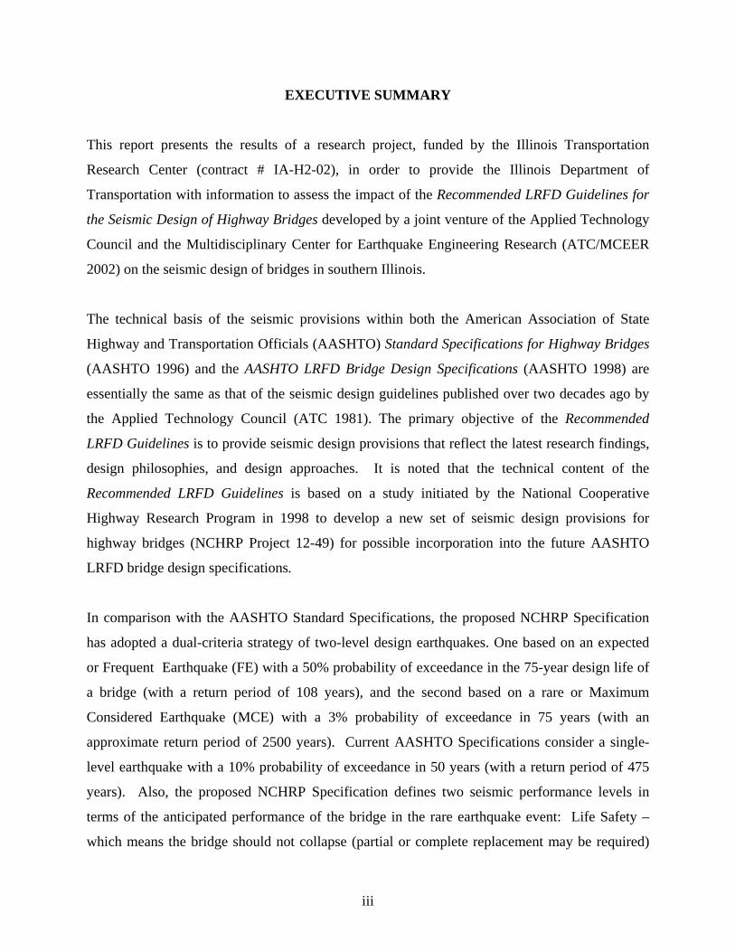
For the Johnson County bridge, design earthquake response spectra for both NCHRP 100-year
and 2500-year events (Frequent Earthquake, FE, and Maximum Considered Earthquake, MCE,
respectively) are compared with the AASHTO design earthquake response spectrum (500-year
event) in Figure 3.2.
For NCHRP and AASHTO bridge models, the results of free vibration analysis are summarized
in Tables 3.3 and 3.4, respectively, where the main mode shapes are shown.
3.4 Substructure Design Forces
To obtain the design member forces according to the proposed NCHRP Specification, 100%
earthquake forces in one direction are combined with 40% earthquake forces in the other
direction (instead of 30% used in the AASHTO Specifications), and then they are reduced by the
18

appropriate Response Modification factors (R-factors) which depend on not only the type of
substructure element (as in the AASHTO Specification) but also on the performance level,
SDAP, and period of the structure (e.g., R of 1 and 0.9 are used in the wall piers for the MCE
and FE, respectively, in comparison to an R of 2 given in the AASHTO Specifications).
The summary of the design forces and moments in the fixed and expansion piers are given in
Figures 3.1 and 3.2 for the proposed NCHRP Specification and the AASHTO Specifications,
respectively. It is noted that the results for the MCE are considerably larger than the
corresponding values for the FE, thus, the MCE design forces control the final design.
3.5 Wall Design
The walls are designed considering moment and axial force interaction effects, using the PCA
column design program (PCA 1999). The superstructure model is considered pinned at the top
of one pier, and free to move longitudinally at the top of the expansion pier. This results in
moments on the fixed pier being larger than those on the expansion pier.
When designed according to the AASHTO Specifications, both piers are designed to have the
same wall thickness (26 inches). The vertical reinforcing for the fixed pier is 2.27 times heavier
(46 # 9) than the expansion pier (46 #6) due to the higher moments. Transverse reinforcement is
similar ( #6 @ 12”) for both piers.
When designed according to the NCHRP provisions, the fixed pier wall thickness is 10” thicker
than the wall in the expansion pier (36” vs. 26”), and the vertical reinforcing for the fixed pier is
almost 2.5 times more that of the expansion pier (2.5% vs 1.01%) due to the higher moments.
For the fixed pier the transverse reinforcement in the strong direction is 1.55 times than that of
the expansion piers (#4 and #5 at 5’’spacing, respectively). The transverse reinforcing steel used
in the weak direction at the plastic hinge regions (about 6’ from the bottom of the wall) is
extensive. For the fixed bent, the first layer consists of 82 legs #5 rebars (anti-buckling
reinforcement) while the second layer consists of 41 legs #4 rebars with 4” spacing used between
the layers. For the expansion bent, the first layer consists of 29 legs #4 rebars (anti-buckling
19

reinforcement) while the second layer consists of 19 legs #3 rebars with 4” spacing used between
the layers.
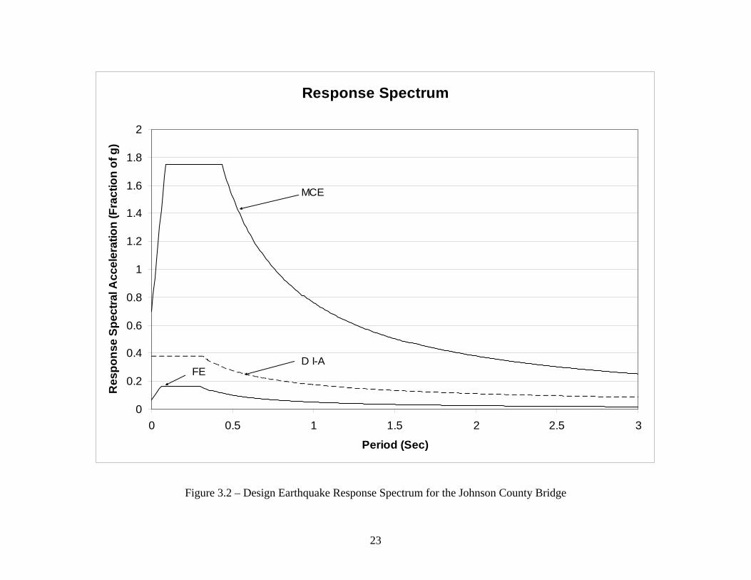
Figures 3.5-6 and Figures 3.7-8 provide design detail summaries for the walls at the fixed and
expansion piers designed according to the AASHTO Specifications and the proposed NCHRP
Specification, respectively.
3.6 Foundation Design
Circular cast-in-place drilled shafts are used as piles. Individual pile stiffness is calculated based
on results from the computer program LPILE. Pile load-deformation plots are produced and pile
properties are based on a secant stiffness calculation. Group effects are only considered in the
design of the foundation according to the proposed NCHRP Specification where pile centers
have to be as close as 3D apart using the P-multiplier method specified by the IDOT Technical
Review Panel (Walsh et al. 2000). The group effects are not used in this design according to the
AASHTO Specifications since pile centers could be reasonably placed at 5D apart. Piles were
design based on the forces obtained from the finite element analysis. PCA Column software was
used to verify the design adequacy of the pile vertical rebars selected.
When designed according to the AASHTO Specifications, eight 18” piles are used for both piers.
However, twelve and six 36” diameter piles are used at the fixed bent and the expansion bent,
respectively, when designed according to the proposed NCHRP Specification.
Figures 3.9, and Figures 3.10-11 provide foundations design detail summaries for the piles, pile
caps, and connections at the fixed and expansion piers designed according to the AASHTO
Specifications and the proposed NCHRP Specification, respectively.
20

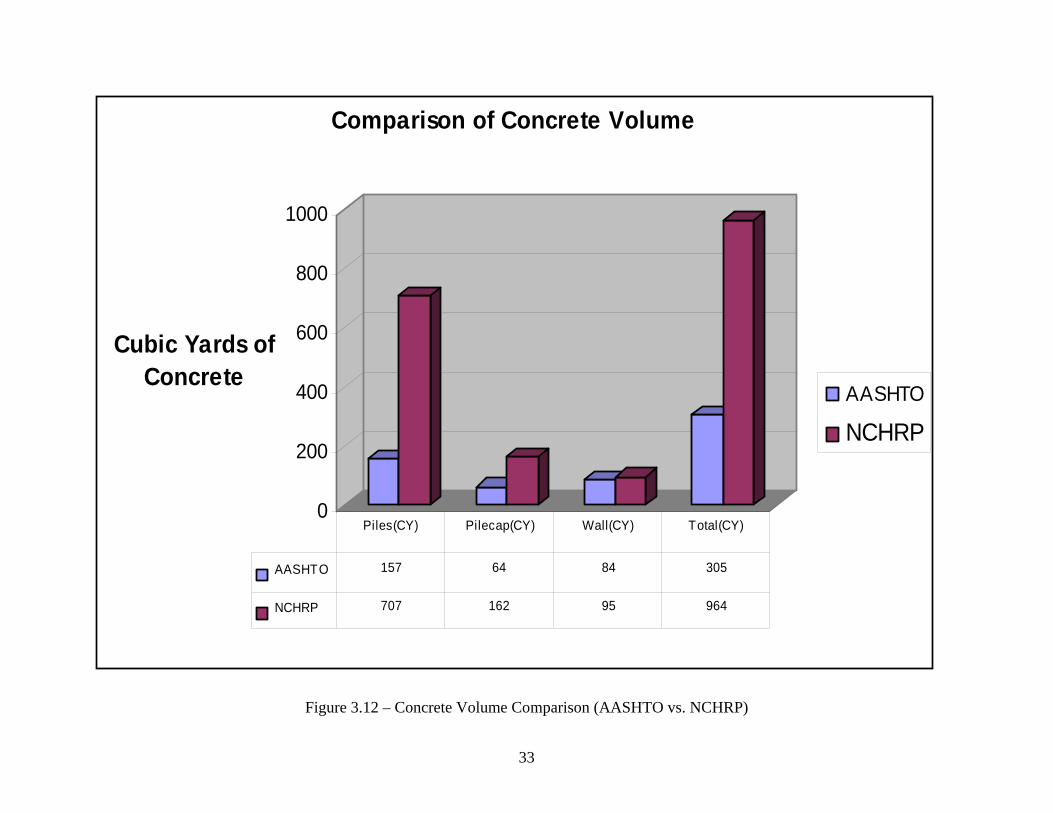
3.7 Material and Cost Comparisons
Figures 3.12 and 3.13 show a detailed comparison of the amount of concrete and steel used in the
design of substructures of the Johnson County bridge using the AASHTO Specifications and the
proposed NCHRP Specification.
Concrete volume and reinforcing steel weight needed for the substructures designed according to
proposed NCHRP provision are 3.16 and 2.39 times the corresponding values obtained using
AASHTO Standard Specifications. It is noted that the main contributors to the significant
increase in concrete use is the increased size of the foundations used (number of piles, diameter
of the piles, and the size of the pile caps) while the primary contributors to the significant
increase in using steel are the increased amount of reinforcement in the piles and the transverse
reinforcement in the walls when designed according to the NCHRP provisions.
The cost comparisons of the substructure (interior bents) designed according to the AASHTO
and the proposed NCHRP Specifications based on estimated quantities and the unit costs
obtained from the 2002 Means Heavy Construction Data and IDOT bid tabulations are given
below.
AASHTO NCHRP Concrete: $81,450 $141,480 Epoxy Coated Rebars: $28,500 $68,310 Drilled CIP Piles: $13,980 $33,860 --------------------------------------------------------------------------------------------------------------- Total Cost: $123,930 $243,650
It is observed that the estimated total construction cost of using the proposed NCHRP
Specification is 1.97 times the value obtained using the AASHTO Specifications.
21

Figure 3.1 – Johnson County Existing Bridge Geometry -- Side View, Pier Elevation, and Superstructure
22
Response Spectrum
0
0.2
0.4
0.6
0.8
1
1.2
1.4
1.6
1.8
2
0 0.5 1 1.5 2 2.5 3
Period (Sec)
Res
pons
e Sp
ectra
l Acc
eler
atio
n (F
ract
ion
of g
)
MCE
D I-AFE
Figure 3.2 – Design Earthquake Response Spectrum for the Johnson County Bridge
23

Mode Shape 4 (UX: 18%)Mode Shape 1 (UX: 69%)
Figure 3.3 – Free Vibration Results (NCHRP MCE Model)
Mode Shape 3 (UY: 77%)
M O D A L P A R T I C I P A T I N G M A S S R A T I O S
MODE PERIOD INDIVIDUAL MODE (%)UX UY UZ
1 0.4035 68.93 0.00 0.002 0.2898 0.00 22.88 0.003 0.2067 0.00 77.00 0.004 0.1683 18.24 0.00 0.005 0.1292 0.98 0.00 4.366 0.1133 6.83 0.00 0.547 0.0884 5.02 0.00 0.008 0.0687 0.00 0.00 0.259 0.0612 0.00 0.00 42.3210 0.0431 0.00 0.07 0.0011 0.0392 0.00 0.00 0.4512 0.0389 0.00 0.00 0.0013 0.0303 0.00 0.05 0.0014 0.0289 0.00 0.00 25.5115 0.0242 0.00 0.00 9.9216 0.0239 0.00 0.00 9.3517 0.0210 0.00 0.00 0.8118 0.0181 0.00 0.00 0.0919 0.0178 0.00 0.00 0.0020 0.0171 0.00 0.00 0.00
100.00 100.00 93.61
With Spring for the MCE
Mode Shape 2 (UY: 23%)
24

Mode Shape 4 (UX: 18%) Mode Shape 1 (UX: 69%)
Figure 3.4 – Free Vibration Results (AASHTO Model)
Mode Shape 3 (UY: 77%)
M O D A L P A R T I C I P A T I N G M A S S R A T I O S
MODE PERIOD INDIVIDUAL MODE (%)UX UY UZ
1 0.4035 68.93 0.00 0.002 0.2898 0.00 22.88 0.003 0.2067 0.00 77.00 0.004 0.1683 18.24 0.00 0.005 0.1292 0.98 0.00 4.366 0.1133 6.83 0.00 0.547 0.0884 5.02 0.00 0.008 0.0687 0.00 0.00 0.259 0.0612 0.00 0.00 42.3210 0.0431 0.00 0.07 0.0011 0.0392 0.00 0.00 0.4512 0.0389 0.00 0.00 0.0013 0.0303 0.00 0.05 0.0014 0.0289 0.00 0.00 25.5115 0.0242 0.00 0.00 9.9216 0.0239 0.00 0.00 9.3517 0.0210 0.00 0.00 0.8118 0.0181 0.00 0.00 0.0919 0.0178 0.00 0.00 0.0020 0.0171 0.00 0.00 0.00
100.00 100.00 93.61
With Spring for the MCE
Mode Shape 2 (UY: 23%)
25
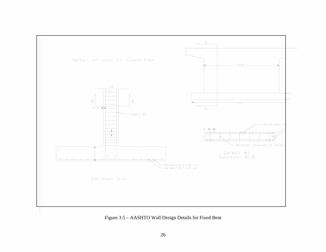
Figure 3.5 – AASHTO Wall Design Details for Fixed Bent
26

Figure 3.6 – AASHTO Wall Design Details for Expansion Bent
27

Figure 3.7 – NCHRP Wall Design Details for Fixed Bent
28

Figure 3.8 – NCHRP Wall Design Details for Expansion Bent
29

Figure 3.9 – AASHTO Foundation Design Details for Fixed and Expansion Bents
30
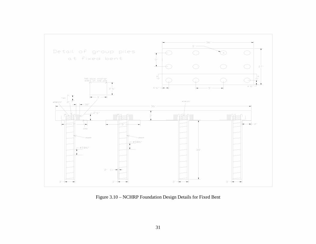
Figure 3.10 – NCHRP Foundation Design Details for Fixed Bent
31

Figure 3.11 – NCHRP Foundation Design Details for Expansion Bent
32
0
200
400
600
800
1000
Cubic Yards of Concrete
Comparison of Concrete Volume
AASHTO
NCHRP
AASHTO 157 64 84 305
NCHRP 707 162 95 964
Piles(CY) Pilecap(CY) Wall(CY) Total(CY)
Figure 3.12 – Concrete Volume Comparison (AASHTO vs. NCHRP)
33

0.00
10.00
20.00
30.00
40.00
50.00
60.00
70.00
Kips of Steel
Comparison of Steel Weight
AASHTO
NCHRP
AASHTO 8.03 5.04 1.41 5.72 6.49 2.33 29.02
NCHRP 21.01 12.15 2.67 2.70 7.24 16.32 62.10
Piles
(Long)
Piles
(Trans)
Pilecap
(Long)
Pilecp
(Trans)
Wall
(Long)
Wall
(Trans)Total
Figure 3.13 – Reinforcing Steel Weight Comparison (AASHTO vs. NCHRP)
34

Table 3.1 – NCHRP Seismic Design Force and Displacement Result Summary
35

Table 3.2 – AASHTO Seismic Design Force and Displacement Result Summary
36

4.1 Introduction
The existing two-span bridge with equal span le
consists of a 195 mm
on eleven 1.
fixed in both longitudinal and transverse dir
superstructure is only fixed in
longitudinal direction by Type I el
overall skew of 26.53
37
4. SEISMIC ANALYSIS AND DESIGN INVESTIGATION OF
ST. CLAIR COUNTY BRIDGE
The main purpose of this investigation is to provide the Illinois Department of Transportation
(IDOT) with data to assess the impact of the proposed NCHRP Specification on the seismic
design of the St. Clair County bridge in southern Illinois. The bridge substructure pier is
redesigned for earthquake loads using the proposed NCHRP Specification where the
“Operational” performance objective is selected. Since the existing bridge was designed in 1999
according to the AASHTO Specifications, only the strength adequacy of the existing bridge is
checked, and substructure cost comparison between the two designs is presented. Detailed
computations for design and analysis of this bridge according to the proposed NCHRP
Specification and the analysis and design check according to the AASHTO Specifications are
given in Appendices C and D, respectively.
4.2 Existing Structure
ngths of 41.50 m (136 ft). The superstructure
(7.7 in.) thick and 20.8 m (64 ft) wide reinforced concrete slab supported
372 m (48 in.) deep plate girders spaced at 1.905 m (6.25 ft). The superstructure is
ections at the interior bent. However, the
the transverse direction at the abutments (free to move in the
astometric expansion bearings). In addition, the bridge has an o at the abutments and interior bent. The abutments are non-integral and
are supported by two rows of piles arranged in nine alternate spaces of 2.5 m (8.2 ft). The front
row piles are battered. The 4.7 m (15.4 ft) long wing walls are laid along the skew.
The interior bent consists of five tapered reinforced concrete columns with cross-sectional
dimensions of 1.75 m (5.74 ft) wide at the top and 1.125 m (3.69 ft) wide at the bottom, and
0.9m (2.95 ft) thick along the column height supported on 2.9 m (9.5 ft) wide, 10.195 m (33.5 ft)

long, and 0.9 es) of which
two rows are battered. Existing es 4.1 and 4.2.
and Basic Seismic Parameters
m (2.95 ft.) thick footing with three rows of H plies (36 HP 12x53 pil
bridge geometry is shown in Figur
4.3 SAP Modeling
ccording to the proposed NCHRP Specifications and with the provided geotechnical
the soil profile used at the bridge site was produced using the
vailable boring logs is given in Appendix G), the St. Clair Country Bridge site is classified as
According to the AASHTO Specifications, Division 1A, Seismic Performance Category (SPC)
The bridge is modeled using SAP 2000 beam elements. The model is a “stick figure” model,
where the stiffnesses and masses of the members of the superstructure and substructure, are
converted into equivalent beam elements. The foundation of the bridge is modeled using
springs, whose stiffnesses are calculated based on the pile stiffnesses. The existing foundation
configuration is used in the AASHTO model. However, the foundation model used in the
NCHRP model requires iterations since the piles are not designed initially and the spring
stiffnesses, and hence the finite element analysis, has to be updated throughout the design phase.
Steel piles are used for the analysis. Concrete with a compressive strength of 24 MPa (3500 psi)
and reinforcing steel with yield strength of 400 MPa (58,000 psi) are used.
A
information at the bridge site (
a
Site Class “D” with Seismic Hazard Level of IV where Seismic Design and Analysis Procedure
(SDAP) “D” and Seismic Detailing Requirements (SDR) of 6 are used to obtain the
“Operational” performance objective. No potential for liquefaction exists at the given site. The
Elastic Response Spectrum Method is required. Thus, the SAP model is analyzed using modal
analysis, and then the response spectrum procedure is used to distribute the required seismic
forces and displacements throughout the structure. The structure is analyzed independently in
both the longitudinal and transverse directions where an adequate number of modes is included
in each direction to obtain at least 90% mass participation.
of “B” is used with the Soil Profile Type III with Site Coefficient of S = 1.5 and the Acceleration
Coefficient of A = 0.1125 g.
38

For the St. Clair County Bridge, design earthquake response spectra for both NCHRP 100-year
and 2500-year events (Frequent Earthquake and Maximum Considered Earthquake, respectively)
re compared with the AASHTO design earthquake response spectrum (500-year event) in
, the results of free vibration analysis are
ummarized in Figures 4.4 and 4.5, respectively, where the main mode shapes are shown.
a
Figure 4.3. For NCHRP and AASHTO bridge models
s
4.4 Substructure Design Forces
To obtain the design member forces according to the proposed NCHRP Specification, 100%
earthquake forces in one direction are combined with 40% earthquake forces in the other
direction (instead of 30% used in Division 1-A of the AASHTO Specifications), and then they
are reduced by the appropriate Response Modification factors (R-factors) which depend not only
the type of substructure element (as in the AASHTO Specifications) but also on the performance
level, SDAP, and period of the structure (e.g., R of 1.5 and 0.849 are used in the multi column
ent for the MCE and FE, respectively, in comparison to an R of 5 given in the AASHTO b
Specification).
The summary of the design forces and moments in the interior bent are given in Tables 4.1 and
4.2 for the proposed NCHRP Specification and the AASHTO Specifications, respectively. It is
noted that the results for the MCE are considerably larger than the corresponding values for the
FE, thus, the MCE design forces control the final design.
4.5 Reinforced Concrete Column Design and Connections
The reinforced concrete columns in the interior bent are designed considering moment and axial
force interaction effects, using the PCA column design program. The reinforcing steel ratios
used in the existing columns are 0.92% and 1.44% at the top and bottom of the columns,
spectively, are found adequate to resist the AASHTO design moments and axial forces. The re
column shear capacities are found to be adequate with use of minimum shear reinforcement.
since the factored shear forces are less than twice the provided design capacities.
39

When designed according to the proposed NCHRP Specification, the column dimensions need to
be increased considerably at the bottom to 56”x 35” and slightly at the top to 70”x 35” and the
reinforcing steel ratios increase to 2.64% at the top and 3.31% at the top. Anti-buckling steel
(No. 6 at 4 in. spacing) governs the design of transverse steel in plastic hinge regions.
Column to cap beam and column to crash wall connections at the interior fixed bent are detailed
s. No special connection detailing is required for this design
nder AASHTO Division I-A. Standard splices, hooks, tension development, etc. are detailed as
according to the NCHRP provision
u
required by normal design practice. Figures 4.6a-b show the overall geometry and the design
details for the interior bent designed according to the proposed NCHRP Specification.
4.6 Foundation Design
In the existing structure, 36 HP 12 x 53 are used in three rows (24 of which are battered).
Approximate length of each pile in place is 78’. The piles are analyzed using the combined
moment and axial force obtained from a combination of the LPILE results and the response
pectrum analysis. The worst case pile is determined to be loaded approximately 17% over the
he substructure foundation design was investigated for several abutment lateral-resisting
out soil resistance in transverse
irection) for the MCE per request from the TRP. It was found that it was more economical not
gure 4.7. The
footing length and width are increased to 131.25 ft and 31.25 ft. Individual pile stiffness is
s
design capacity from the AASHTO interaction equation. Since this number is not unreasonably
high, the existing pile configuration is used in the cost comparisons. The abutments are
restrained in the transverse direction and free in the longitudinal direction.
T
options (roller, pin, springs with soil resistance, springs with
d
to rely on the abutments to resist the earthquake load in the transverse direction. Thus, the
abutments were idealized as rollers in the SAP model (the results were presented to TRP in the
June 2003 meeting).
For the NCHRP design, five rows of driven vertical steel piles (HP 14 x 117) spaced at 6.25 ft.
are found necessary to resist the design forces (105 piles total) as shown in Fi
40

calculated based on results from the computer program LPILE. Pile load-deformation plots are
produced and pile properties are based on a secant stiffness calculation. The group effects are
not used in either AASHTO or NCHRP designs since pile spacing is greater than 5d.
4.7 Material and Cost Comparisons
oncrete volume and reinforcing steel weight needed for the substructures designed according to
ecification are 3.65 and 4.3 times the corresponding values obtained
sing the AASHTO Specifications. It is noted that the main contributors to the significant
ns are given below.
Figures 4.8, 4.9, and 4.10 show a detailed comparison of the amount of concrete, steel and the
total length of driven steel piles used in the design of substructures of the St. Clair County Bridge
using the AASHTO Specifications and the proposed NCHRP Specification.
C
the proposed NCHRP Sp
u
increase in concrete use is the increased size of the footing while the primary contributors for
using more reinforcing steel are the increased amount of reinforcement in the footing and the
columns.
The cost comparisons based on estimated quantities and the unit costs obtained from the 2002
Means Heavy Construction Data and IDOT bid tabulations of the substructure (interior bent)
designed according to the AASHTO and the proposed NCHRP Specificatio
AASHTO NCHRP Concrete: $69,890 $255,300 Epoxy Coated Rebars: $31,300 $134,800 HP Piles: ---------------------------
$66,830 $489,000 ------------------------------------------------------------------------------------
Total Cost: $168,020 $879,100
It is observed that the estimated NCHRP substructure interior bent construction cost is 5.23 times
more than the value obtained using the AASHTO Specifications.
41

42
. Count idge Ge nd Supe e
ometry -- Side View ay Existing BrClairFigure 4.1 – St rstructur
Centerline of Symm.
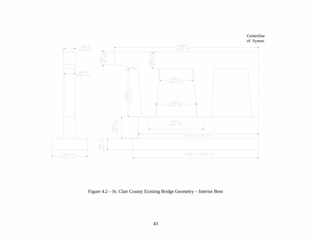
Centerline of Symm.
Figure 4.2 – St. Clair County Existing Bridge Geometry – Interior Bent
43

Figure 4.3 – Design Earthquake Response Spectrum for the St. Clair County Bridge
Response Spectrum
00.10.20.30.40.50.60.70.80.9
0 0.5 1 1.5 2 2.5 3Period (sec)
Resp
onse
spe
ctra
l Acc
eler
atio
n (F
ract
ion
of g
) MCE
D1-A
FE
44
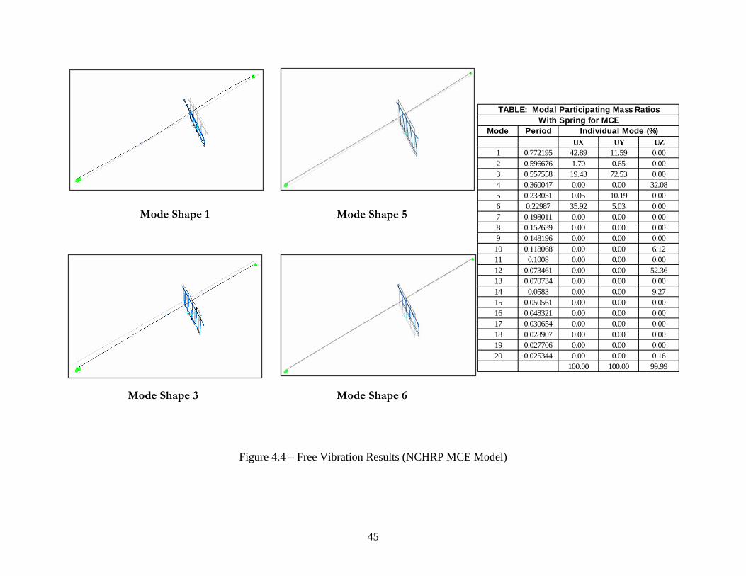
Mode Shape 1
Mode Shape 3
Mode Shape 5
Mode Shape 6
Mode PeriodUX UY UZ
1 0.772195 42.89 11.59 0.002 0.596676 1.70 0.65 0.003 0.557558 19.43 72.53 0.004 0.360047 0.00 0.00 32.085 0.233051 0.05 10.19 0.006 0.22987 35.92 5.03 0.007 0.198011 0.00 0.00 0.008 0.152639 0.00 0.00 0.009 0.148196 0.00 0.00 0.0010 0.118068 0.00 0.00 6.1211 0.1008 0.00 0.00 0.0012 0.073461 0.00 0.00 52.3613 0.070734 0.00 0.00 0.0014 0.0583 0.00 0.00 9.2715 0.050561 0.00 0.00 0.0016 0.048321 0.00 0.00 0.0017 0.030654 0.00 0.00 0.0018 0.028907 0.00 0.00 0.0019 0.027706 0.00 0.00 0.0020 0.025344 0.00 0.00 0.16
100.00 100.00 99.99
Individual Mode (%)With Spring for MCE
TABLE: Modal Participating Mass Ratios
Figure 4.4 – Free Vibration Results (NCHRP MCE Model)
45

de Shape 1 Mo Mode Shape 2
TABLE: Modal Participating Mass RatiosMode Period UX UY UZNumber Sec % % %
1 1.0392 40.16 0.45 02 0.6622 34.43 8.99 03 0.6434 0 0 98.664 0.6002 2.08 0.07 05 0.4894 0 0 06 0.3609 16.02 49.67 07 0.3214 0 0 0.248 0.3168 7.30 30.02 09 0.1644 0.01 7.00 0
10 0.1482 0 0 011 0.1115 0 0 1.0012 0.0707 0 0 013 0.0613 0 0 0.1014 0.0506 0 0 015 0.0359 0 0 016 0.0305 0 0.03 017 0.0289 0 0.05 018 0.0271 0 2.69 019 0.0259 0 0 020 0.0246 0 0 021 0.0243 0 0.17 022 0.0237 0 0.06 023 0.0230 0 0 024 0.0225 0 0.03 025 0.0205 0 0 0
100.00 99.23 100.00
Figure 4.5 – Free Vibratio Results (AASHTO Model)
MMode Shape 6 ode Shape 8
n
46

Figure 4.6a – NCHRP Design Details for Interior Bent
8 # 5 at each side
9 # 5 at each side
Plastic hinge zone36 #6 @ 4 in
Half of the MaximumCross section Dimension=35 in
9 # 5 Clamp
11 # 5 @ 3 in
9 # 5 Clamp
Ah= 6 # 9
A
Ah= 6 # 9
A
16 # 5 @ 3 in
42 # 11
SECTION A-A
104 # 11
103 # 9
HP 14X117
47

5 '- 7 "
4 '- 9 "2 '- 1 1 "
3 '- 3 "
2 5 # 9
6 3 # 1 1
6 # 6
2 8 # 9N o .5 @ 1 0
6 # 6
N o .5 @ 1 0
2 8 # 9
C a p b e a m C r o s s - s e c t io n
H P 1 4 X 1 1 71 '
Figure 4.6b – NCHRP Design Details for Interior Bent (cont.)
48

131'-3"
31'-3"
6'-3"3'-2"
49
Figure 4.7 – NCHRP Interior Bent Footing Geometry (Piles Used: 105 HP 14x117)

Comparison of Concrete Volume
0
100
200
300
400
500
600
Cub
ic Y
ard
AASHTONCHRP
AASHTO 70 2 32 44 147
NCHRP 456 2 35 44 537
Footing Crash Wall
Columns Cap Beam
Total
Figure 4.8 – Concrete Volume Comparison (AASHTO vs. NCHRP)
50
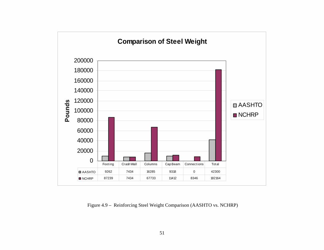
Comparison of Steel Weight
020000
4000060000
80000100000120000
140000160000
180000200000
Pou
nds
AASHTONCHRP
AASHTO 9262 7434 16285 9318 0 42300
NCHRP 87239 7434 67733 11412 8346 182164
Foot ing Crash Wall Columns Cap Beam Connect ions Tot al
Figure 4.9 – Reinforcing Steel Weight Comparison (AASHTO vs. NCHRP)
51

Comparison of Piles Length
0100020003000400050006000700080009000
Feet AASHTO
NCHRP
AASHTO 2893NCHRP 8438
Piles
Figure 4.10 – Pile Length Comparison (AASHTO vs. NCHRP)
52

Table 4.1 – NCHRP Seismic Design Force Result Summary
Longitudinal Combination - 100% load in X direction + 40% load in Y direction + Dead load Transverse Combination - 100% load in Y direction + 40% l ad in X direction + Dead load
Shear 2 Shear 3 Moment 2 Moment 3 Axial Shear 2 Shear 3 Moment 2 Moment 3 Axial kips kips kip-ft kip-ft kips kips kips kip-ft kip-ft kips
top 231 406 3369 996 1072 304 307 2554 1311 936bottom 233 419 1715 3859 1100 307 317 1299 5083 964
top 231 527 4893 997 794 304 399 3709 1314 726bottom 233 540 1681 3860 822 307 409 1274 5084 754
top 231 541 5070 997 517 304 410 3844 1314 517bottom 233 553 1335 3716 545 307 420 1011 4895 545
Central Column
Middle Column
LongitudinalFinal Design Forces and Moments (EQ+DL) By R=1.5
NCHRP - MCETransvers
Location
Exterior Column
Shear 2 Shear 3 Moment 2 Moment 3 Axial Shear 2 Shear 3 Moment 2 Moment 3 Axial kips kips kip-ft kip-ft kips kips kips kip-ft kip-ft kips
top 18 37 321 77 567 36 44 368 154 574bottom 18 40 161 168 595 36 45 187 254 602
top 18 49 465 77 542 36 57 535 154 546bottom 18 51 159 309 570 36 58 184 608 574
top 18 50 482 77 517 36 59 554 154 517bottom 18 53 158 309 545 36 60 183 608 545
Exterior Column
LongitudinalFinal Design Forces and Moments (EQ+DL) By R=0.849
NCHRP - FETransverse
Central Column
Middle Column
Location
o
53

Table 4.2 – AASHTO Seismic Design Force Result Summary
Final Design Forces and Moments AA
+DL SHTO
Load Combination 1 - (1.0*EQL + 0.3*EQT)+DL Load Combination 2 - (0.3*EQL + 1.0*EQT)
Longitudinal (R =3) Transverse (R =5) Longitudinal (R =3) Transverse (R =5)
Shear 3 Moment 2 Shear 2 Moment 3 Shear 3 Moment 2 Shear 2 Moment 3 Lo Axial kips
cation kips kip-ft kips kip-ft
Axial kips kips kip-ft kips kip-ft
top 42 347 35 151 335 40 323 19 82 346 Exterior Column bottom 42 172 35 581 365 40 161 19 312 377
top 54 489 35 151 420 50 457 19 82 425 Middle Column bottom 54 173 35 581 449 50 163 19 312 454
top 55 507 35 151 503 52 474 19 82 503 Central Column
bottom 55 173 35 581 530 52 163 19 312 530 R = 3.0 (Sing
le Columns); (Substructure)
R = 5.0 (Multiple column bent); (Substructure)
COMD1 - 10COMD2 - 10 rection + Dead load
0% load in X (longitudinal) direction + 30% load in Y (transverse) direction + Dead load 0% load in Y (transverse) direction + 30% load in X (longitudinal) di
54

55
5. SEISMIC ANALYSIS AND DE ON OF
PULASKI COUNTY BRIDGE
5.1 Introduction
SIGN INVESTIGATI
The main purpose of ment of Transportation
(IDOT) with adequate information to assess the impact of the proposed NCHRP Specification on
the seismic design of the Pulaski County bridg Southern Illinois. The bridge substructure
piers are redesigned for earthquake loads using both the seismic provisions given in Division 1A
of the AASHTO Specifications and the proposed NCHRP Specification where the “Operational”
perform tations for design and analysis of this bridge
accord the posed N RP Specifications AS Specification are given in
Appendices E and F, respectively.
5.2 Existing Structure
this investigation is to provide the Illinois Depart
e in
ance objective is
ing to
specif
CH
ied. Detailed compu
pro and the A HTO
The existing four-span bridge with span lengths of 40’- 8”, 73’- 3”, 73’ -3”, and 40’- 8” was
designed in 1965. Its superstructure consists of a 6.5” thick (30’
supported on five W x t 6’- 6” (o.c.). The superstructure is fixed in
both longitudinal and transverse directions at the second pier by bol
rocker the other ents allowing it to move freely in the
longitudinal direction while it is re ansvers re
of hamm at the bottom, 12’- 00”
2’-6” thick reinforc ngs and two rows of
battered H piles. Existing bridge geometry is shown in Figures 5.1-3.
5.3 SAP Modeling and Basic Seismic Parameters
wide) reinforced concrete slab
ction. All interior bents consist
33
pie
ed concre
130 steel girders spaced a
sters, and it is attached by
s to
erhead piers (15’- 6” wide
rs and the
str
non
ain
-in
ed
te
in
gra
th
l abutm
e tr e di
wide at the narrow section at the top,
te walls) supported on 2’-3’’ thick footi
The bridge is modeled using SAP 2000 beam ents. The m odel,
where the stiffnesses and masses of the me of the superstructure and substructure are
converted into equivalent beam e ents. The foundation of the bridge is modeled using
elem
mbers
odel is a “stick figure” m
lem

springs, whos e foundation
model requires iteration, since and the spring stiffnesses, and
ence the finite element analysis, has to be updated throughout the design phase. Steel piles are
d Level of IV where Seismic Design and Analysis Procedure
DAP) “D” and Seismic Detailing Requirements (SDR) of 6 are used to obtain the
e objective. No potential for liquefaction exists at the given site. The
lastic Response Spectrum Method is required. Thus, the SAP model is analyzed using modal
or the Pulaski County Bridge, design earthquake response spectra for both NCHRP 100-year
um Considered Earthquake, respectively)
re compared with the AASHTO design earthquake response spectrum (500-year event) in
e stiffnesses are calculated based on the pile stiffnesses. Note that th
the piles are not designed initially
h
used for analysis.
Several individual models of the hammerhead piers were considered to verify that the stick
model is capturing the dynamic behavior of piers. After some finite element studies of varying
complexity, it was determined that the stick model would properly model the piers as long as the
rotational inertia of the deck was considered in the model.
According to the proposed NCHRP Specification and with the provided geotechnical
information at the bridge site (see Appendix G), the Pulaski Country Bridge site is classified as
Site Class “D” with Seismic Hazar
(S
“Operational” performanc
E
analysis, and then the response spectrum procedure is used to distribute the required seismic
forces and displacements throughout the structure. The structure is analyzed independently in
both the longitudinal and transverse directions where an adequate number of modes is included
in each direction to obtain at least 90% mass participation.
According to the AASHTO Specifications, Division 1A, Seismic Performance Category (SPC)
of “C” is selected where the Soil Profile Type III with Site Coefficient of S = 1.5 and the
Acceleration Coefficient of A = 0.22g are used.
F
and 2500-year events (Frequent Earthquake and Maxim
a
Figure 5.4.
56

For NCHRP and AASHTO bridge models, the results of free vibration analysis are summarized
in Figures 5.5 and 5.6, respectively, where the significant mode shapes are shown.
5.4 Substructure Design Forces
ors (R-factors) which depend not only
e type of substructure element (as in the AASHTO Specifications) but also on the performance
erably larger than the corresponding
alues for the FE, thus, the substructure design is governed by the MCE design forces (see
To obtain the design member forces according to the proposed NCHRP Specification, 100%
earthquake forces in one direction are combined with 40% earthquake forces in the other
direction (instead of 30% used in Division 1-A of the AASHTO Specifications), and then they
are reduced by the appropriate Response Modification fact
th
level, SDAP, and period of the structure. For example, R of 1 and 1.5 are used in the piers acting
as a wall pier in the strong direction and a single column in the week direction, respectively, for
the MCE, and R of 0.76 is used for the FE in comparison to R of 2 and 1.0 used for flexure and
shear, respectively, in the AASHTO Specifications.
After several trials due to the high intensity of the seismic design forces in fixed bent in case of
NCHRP design, it was decided to redesign the other two expansion bents as fixed bents. The
summary of the design forces and moments in the three piers are shown in Table 5.1 and 5.2 for
the proposed NCHRP Specification and the AASHTO Specifications, respectively. It was found
that the design forces obtained for the MCE were consid
v
Appendix E).
5.5 Wall Design in Hammerhead Piers
The walls are designed considering moment and axial force interaction effects using the PCA
column design program. The superstructure model is considered pinned at the top of fixed pier,
and free to move longitudinally at the top of the expansion piers.
When designed according to the AASHTO specification, fixed and expansion piers are designed
to have the same wall thickness (30’’ and 48’’, respectively), however, the bottom dimension of
57

the hammerhead pier at the fixed bent is increased by 6’’ (from 15’ – 6” to 16’). For ease of
comparison, the same pier dimensions are used in the NCHRP design for the interior bents as
sed in the AASHTO design.
he vertical reinforcing steel in the middle pier (bent 2) designed according to NCHRP
imilar for both types of bents.
u
T
provisions (196 #11) is 1.44 times the steel used in other piers (136 #11 in bents 1 or 3) where
the transverse reinforcement is similar for both all interior bents. The transverse steel in the
weak direction at the plastic hinge regions at the bottom of the piers (70 legs #5 rebars, used as
anti-buckling reinforcement) is extensive compared to the ones used at the top of the piers (24
legs of #4 rebars).
When designed according to the AASHTO specifications, the vertical reinforcing used in the
fixed pier is almost similar to the one used in the expansion piers (44 #11 vs 42 #11,
respectively) where the transverse reinforcement is s
Figures 5.7 a-b and Figures 5.8 a-b provide design detail summaries for the hammerhead walls
at the fixed and expansion piers designed according to the NCHRP provisions and the AASHTO
specifications, respectively, where special detailing required for the wall to footing connections
by the NCHRP provision are also shown.
5.6 Foundation Design
For the NCHRP design, 40 driven vertical steel HP 14 x 117 piles (in four rows spaced at 70 in.
n forces at each fixed pier (bents 1, 2, and 3 --120
iles total). For the AASHTO design, 15 HP 14 x 89 piles (in three rows of 5) and 10 HP 14 x
verall dimensions of the footings for NCHRP and AASHTO designs are given in Figures 5.7c
o.c.) are found necessary to resist the desig
p
89 piles (in two rows of 5) are used in the fixed pier (bent 2) and expansion piers (bents 1 and 3),
respectively (35 plies total), where all piles are spaced at 6 ft. (o.c.).
O
and Figures 5.8 c-d, respectively. In both designs, the footing length and width are increased to
accommodate the piles. The group effects are not used in either AASHTO or NCHRP designs
58

since pile spacing is greater than 5d (Walsh et al. 2000). Individual pile stiffness is calculated
based on results from the computer program LPILE. Pile load-deformation plots are produced
and pile properties are based on a secant stiffness calculation.
5.7 Material and Cost Comparisons
Figures 5.9, 5.10 and 5.11 show a detailed comparison of the amount of concrete, steel and the
total length of driven steel piles used in the design of substructures of the Pulaski County Bridge
using the AASHTO Specifications and the proposed NCHRP Specification.
Concrete volume and reinforcing steel weight needed for the substructures designed according to
r using more
reinforcing steel are the increased amount of reinforcement in the walls.
nstruction Data and IDOT bid tabulations are given
elow.
AASHTO
the proposed NCHRP Specification are 4.88 and 5.61 times the corresponding values obtained
using AASHTO Specifications. It is noted that the main contributors to the significant increase
in concrete use is the increased size of the footing while the primary contributors fo
The cost comparisons of the substructure (interior bents) designed according to the AASHTO
and the proposed NCHRP Specifications based on estimated quantities and the unit costs
obtained from the 2002 Means Heavy Co
b
NCHRP
$898,420
Concrete: $73,790 $359,450 Epoxy Coated Rebars: $21,700 $121,730 HP Piles: $69,850 $417,240 --------------------------------------------------------------------------------------------------------------- Total Cost: $165,340
It is noted that the estimated total construction cost of using the proposed NCHRP Specification
is 5.43 times the value obtained using the AASHTO Specifications.
59

60
Figure 5.1 – dge
Existing Bri
Figure 5.2 – Existing Bridge Geom
Geometry – Side View
etry – Superstructure

Figure 5.3 – Existing Bridge Geometry – Interior Bent
61

R e s p o n s e S p e c tru m
0
0 .5
1
1 .5
2
2 .5
3
3 .5
0 0 .5 1 1 .5 2 2 .5 3
P erio d (S ec)
Res
pons
e Sp
ectra
l Acc
eler
atio
n (F
ract
ion
of g
)
MC E
D I-A
FE
Figure 5.4 – Design Earthquake Response Spectrum for Pulaski County Bridge
62

Modal Participating Mass Ratios With Spring for MCE
Mode Period INDIVIDUAL MODE(%) UX UY UZ
1 0.485747 45.94 0.00 0.00 2 0.267381 0.45 0.00 0.00 3 0.221216 0.00 0.00 0.00 4 0.213759 0.00 68.76 0.00 5 0.186965 0.00 0.00 13.77 6 0.175687 0.00 9.61 0.00 7 0.149138 2.64 0.00 0.00 8 0.149138 16.32 0.00 0.00 9 0.14573 0.00 20.79 0.00
10 0.12624 0.00 0.00 0.00 11 0.099286 0.00 0.08 0.00 12 0.096843 18.23 0.00 0.00 13 0.093833 0.00 0.00 0.00 14 0.092676 4.48 0.00 0.00 15 0.092676 11.22 0.00 0.00 16 0.091418 0.69 0.00 0.00 17 0.085216 0.00 0.00 20.20 50 0.021368 0.00 0.00 0.00
99.96 99.25 33.96
Mode Shape 1- (UX- 46%) Mode Shape 4- (UY- 67%)
Mode Shape 8- (UX- 17%) Mode Shape 9- (UY- 21%)
Figure 5.5 – Free Vibration Results (NCHRP MCE Model)
63

Modal Participating Mass Ratios Step Period UX UY UZ No. Sec % % % 1 0.9 7 4 68.06 0 0 0.0 0.02 0.293 0.00 17.44 0.003 0.270 0.03 0.00 0.00 4 0.226 0.00 0.00 0.00 5 0.189 00.00 0.00 23.8 6 0.179 5.44 0.00 0.00 7 0.158 0.00 12.86 0.008 0.114 0.00 0.00 0.00 9 0.102 0.00 41.93 0.0010 0.093 0.00 0.00 0.00 11 0.088 80.00 0.00 34.7 12 0.076 0.00 2.15 0.00 13 0.075 0.01 0.00 0.00 14 0.068 0.00 0.00 2.41 15 0.058 0.00 6.24 0.00 16 0.057 0.00 3.74 0.00 17 0.048 0.00 0.00 0.00 18 0.046 50.00 0.00 34.4 19 0.045 4.26 0.00 0.00 20 0.044 2.85 0.00 0.00 21 0.044 0.00 4.99 0.00 2 0.039 0.00 0.00 0.00 223 0.037 0.00 0.15 0.00 24 0.036 0.08 0.00 0.00 25 0.035 0.00 4.15 0.00 26 0.035 9.00 0.00 0.00 27 0.031 0.00 2.68 0.00 28 0.031 0.00 0.00 1.87 29 0.028 0.00 0.55 0.00 Total 89.74 96.87 97.31
Mode Shape 1 (UX - 68%)
Mode Shape 8 (UY- 13%)
Mode Shape 2 (UY - 17%)
Mode Shape 9 (UY - 43%)
64

Figure 5.6 – Free Vibration Results (AASHTO Model)
Figure 5.7a – NCHRP Wall Design Details (Bent 2)
65

Figure 5.7b – NCHRP Wall Design Details (Bents 1 & 3)
66

PILE DATAType: HP 14X117Pile Length: 60'Embedment Length into pile cap: 12"
58'-4"
Figure 5.7c – NCHRP Footing Geometry (All Bents)
67

Figure 5.8a – AASHTO Wall Design Details (Fixed Bent)
68
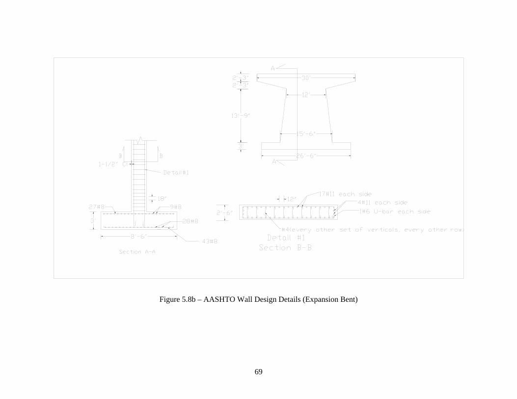
Fi t) gure 5.8b – AASHTO Wall Design Details (Expansion Ben
69

PILE DATAType: HP 14X89Pile Length: 45'Embendment Length into pile cap: 12"
Figure 5.8c – AASHTO Footing Geometry (Fixed Bent)
70

PILE DATAType: HP 14X89Pile Length: 45'Embedment Length into pile cap: 12"
Fi t) gure 5.8d – AASHTO Footing Geometry (Expansion Ben
71

Comparison of Concrete Volume
0
200
400
600
800
Cubi
c Ya
rds
of C
oncr
ete
AASHTONCHRP
AASHTO 70 85 155
NCHRP 605 151 756
Pile cap (CY) Wall (CY) Total (CY)
Figure 5.9 – Concrete Volume Comparison (AASHTO vs. NCHRP)
72

Comparison of Steel Weight
0
50
100
150
200
Ste
el W
eigh
t (Ki
ps)
AASHTONCHRP
AASHTO 8.77 6.43 11.86 2.27 29.33
NCHRP 28.91 52.88 48.92 33.79 164.5
Pile cap long
Pile cap trans
Wall long Wall trans Total
Figure 5.10 – Reinforcing Steel Weight Comparison (AASHTO vs. NCHRP)
73
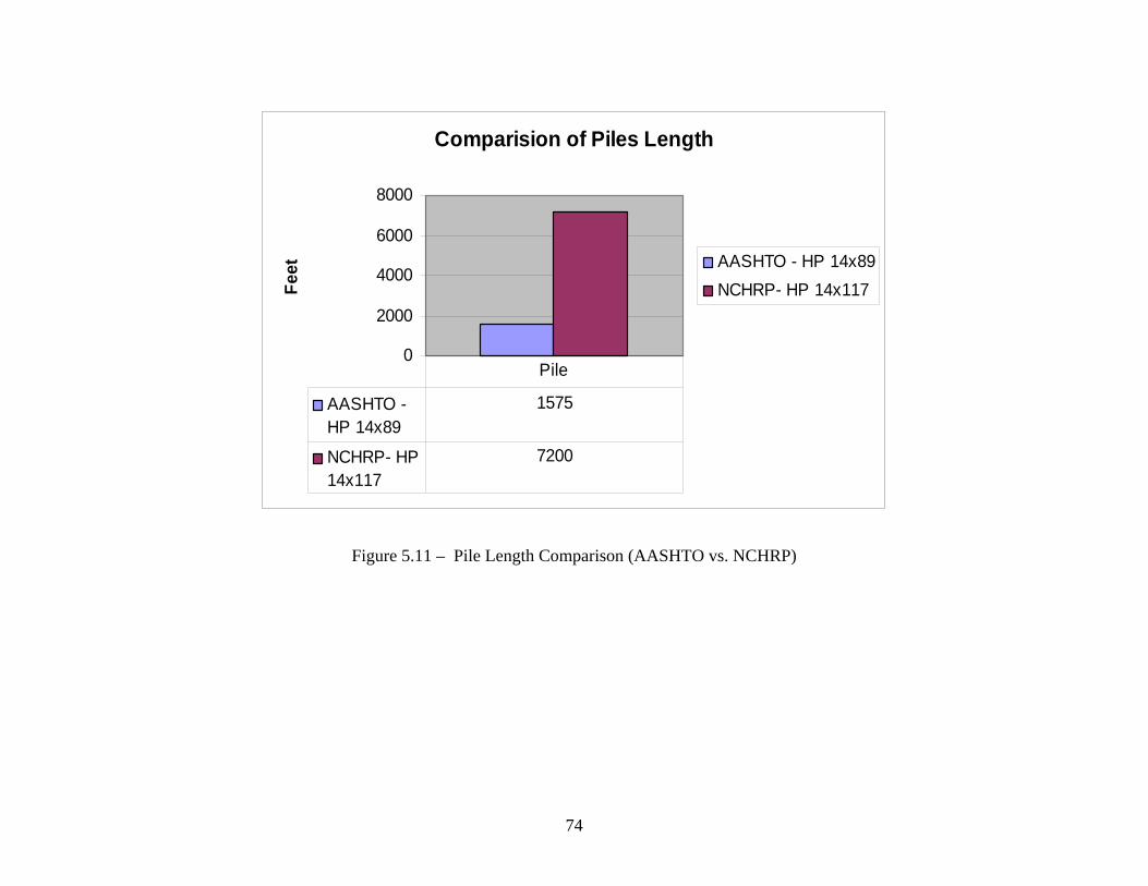
Comparision of Piles Length
0
2000
4000
6000
8000
Feet AASHTO - HP 14x89
NCHRP- HP 14x117
AASHTO -HP 14x89
1575
NCHRP- HP14x117
7200
Pile
Figure 5.11 – Pile Length Comparison (AASHTO vs. NCHRP)
74
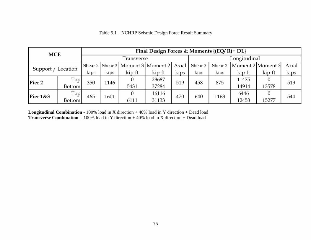
Table 5.1 – NCHRP Seismic Design Force Result Summary
Shear 2 Shear 3 Moment 3 Moment 2 Axial Shear 3 Shear 2 Moment 2 Moment 3 Axialkips kips kip-ft kip-ft kips kips kips kip-ft kip-ft kips
Top 0 28687 11475 0Bottom 5431 37284 14914 13578
Top 0 16116 6446 0Bottom 6111 31133 12453 15277
470 1163640
519
Longitudinal
544
458 875
Final Design Forces & Moments {(EQ/ R)+ DL} Transverse
350 1146 519
Pier 1&3 1601
Pier 2
MCE
Support / Location
465
Longitudinal Combination - 100% load in X direction + 40% load in Y direction + Dead load Transverse Combination - 100% load in Y direction + 40% load in X direction + Dead load
75

Table 5.2 – AASHTO Seismic Design Force Result Summary
COMD1 - 100% load in X (longitudinal) direction + 30% load in Y (transverse) direction + Dead load COMD2 - 100% load in Y (transverse) direction + 30% load in X (longitudinal) direction + Dead load
76
6.1 Introduction
77
6. GROUND MOTION INVESTIGATION AT SOUTHERN ILLINOIS BRIDGE SITES
Adoption of the proposed NCHRP Specification may result in a significant increase in the level
of earthquake forces for bridges located in the Central United States as opposed to the current
AASHTO Specifications. Comparison of the design earthquake response spectrum
year event, 3% probability of exceedance in 75 years (the Maximum Considered Earthquake
which controlled the NCHRP design forces and moments in substructure me ree
that the peak values of the spectrum are significantly higher (2.9
es) than the corresponding values obtained from the AASHTO design earthquake
corresponding to a 475 year event (15% probability of exceedance in 75
e bridge sites given in three southern Illinois counties (Johnson County, St. Clair
purpose of this investigation is to obtain acceleration coefficients at the four sites in southern
d surface levels using existing source paths and odels,
ented by new developments to produce synthetic time
response spectra values at frequencies of interest, uniform hazard spectra, and site
ication factors.
plish the objectives of this study, as stated in Section 2.3, two m
horizontal bedrock motion, and 2) site response analysis. Detailed
descriptions of these tasks are given in the Sections 6.2 and 6.3, and the summary of the results is
presented n Section 6.4.
6.2 Task 1 - Development of Horizontal Bedrock Motions
for the 2500-
ers in all th
site m
ajor tasks are
mb
bridges investigated), indicates
to 5.7 tim
response spectrum
years) at th
County, and Pulaski County).
The
Illinois for both bedrock and groun
and attenuation relationships supplem
histories,
amplif
To accom
identified: 1) development of
Task 1 consists of development of procedures to generate horizontal bedrock motions for four
bridge sites in southern Illinois based on the latest available information. This task includes
three sub-tasks as briefly described below.

Task 1A - Identification of Seismic Source Zones: A detailed literature search was performed to
rces that will be used to characterize seismicity in the New Madrid region
nd any other potential seismic sources in the region including the Wabash region. The research
1 shows the New Madrid seismic zone and other seismic sources
sed by Toro Silva (2001) and also used in this study. Figure 6.2 shows the background seismic
of Attenuation Relationships and Occurrence Rates
identify seismic sou
a
publication by Van Arsdale and Johnston (1999) was used to define seismic sources. In addition,
the report by Toro and Silva (2001) was used to identify seismic sources and to quantify the rates
of occurrence and maximum magnitude for various sources. Recent and ongoing research under
the auspices of the Mid-America Earthquake Center (MAEC) was considered with specific
attention to seismic sources and parameters that are relevant to Illinois.
We believe that the parameters used by Toro and Silva (2001) and Van Arsdale and Johnston
(1999) are more suitable for the study region (see Figure 6.1). The focus of this project was the
State of Illinois; therefore, attentions were focused on seismic sources and parameters that are
prevalent to Illinois. Figure 6.
u
sources used by Toro and Silva (2001) which were also included in this study. Figure 6.3 shows
the three zones used in this study to represent the Wabash seismic zone (adopted from Toro
Silva, 2001).
Task 1B - Evaluation : Seismic attenuation
lationships and occurrence rates are key input parameters for generation of bedrock ground
ask 1C - Generation of Artificial Earthquakes and Bedrock Motions
re
motions. The following attenuation equations were used using equal weights: Atkinson and
Boore (1995); Toro et al. (1997); Frankel et al. (1996); Pezeshk, et al. (1998); and Campbell and
Bozorgnia (2003).
T : In this task, maps of
and the probabilistic consistent
agnitude and epicentral distance. The consistent magnitude and epicentral distance as well as
M (Boore 2003) was used to generate artificial time
appropriate scales were used to determine the seismic hazard
m
attenuation relationships and occurrence rates determined in Task 1B were used to generate
artificial earthquakes with a corresponding bedrock time history at each of the four sites
considered. The computer program SMSI
78

histories for this study. Spectral values were generated for 5 Hz (0.2 seconds), 1 Hz (1 second),
and peak rock accelerations for return periods of 1000 and 2500 years at the selected four sites.
6.3 Task 2 - Site Response Analysis
Task 2 consists of generating peak ground accelerations, 1-second response spectrum
accelerations, and 0.2-second response spectrum accelerations for the selected four sites by
transmitting the seismic waves at the bedrock through soil. This task includes two sub-tasks as
briefly described below.
Task 2A – Site Studied: Site-specific studies were performed for four bridge sites in Illinois:
• Bridge 1. Located in Johnson County (37.433oN, 88.869oW)
• Bridge 2. Located in St. Clair County (38.588oN, 89.912oW)
• Bridge 3. Located in Pulaski County (37.200oN, 89.152oW)
• Bridge 4. Madison County bridge related in Pulaski County (37.283oN, 89.150oW)
Locations of these bridge sites are shown in Figure 6.4 and Figure 6.5.
Task 2B – Determination of Acceleration Coefficients: Site response analyses were performed to
btain representative response spectra at the ground surface based on the propagated NEHRP B-
ined based on the shear wave velocity profile as outlined in Pezeshk, et al.
1998) and Romero and Rix (2001). The shear modulus, Gmax, corresponding to a very small -4
o
C boundary time histories and soil properties obtained from soil boring information at each
bridge. The shear wave velocities for the upper soil strata were obtained from the standard
penetration test (SPT) using the procedure outlined in Pezeshk, et al. (1998) and Wei, et al.
(1999). The shear wave velocities for the remaining depth of soil/rock to the bottom of the soil
boring were determ
(
shear strain (lower than about 3 x 10 percent) was determined based on the in-situ shear wave
velocities. The shear modulus degradation curves and damping ratio curves used were taken
from Pezeshk, et al. (1998).
To determine a better estimate of site characterization for Bridges 3 and 4, Mr. Bob Bauer of
Illinois Geological Survey was contacted. Mr. Bauer identified the Weldon Wells borehole (SS#
79

13430) in Section 15 of T15S, R1W closest to Bridge 3 and Bridge 4 sites. For Bridges 3 and 4,
the boring logs provided at the bridge site were used for the upper strata. The Weldon Wells
orehole is used for the remaining depth of soil/rock to the bottom of the soil boring at the bridge
nce the required input data were collected, site response analyses were performed for the four
elevant data for this study which consisted of the response spectra at the
urface for the 0.2 second and 1.0 second spectral accelerations and the surface time histories.
The spe tr ed from the appropriate
respons s abilistic seismic hazard
analysis (P esponse spectrum at the
ground ur rn
b
sites.
O
selected sites using commercial site response software. Utilizing these data, the program
SHAKE91 (Idriss and Sun, 1992) was used to conduct equivalent linear seismic response
analyses of the assumed horizontally layered soil deposits. The information produced by
SHAKE91 included the r
s
c al accelerations at 0.2 second and 1.0 second were determin
e pectrum based on the attenuation equations used in the prob
SHA). Using these values, the smooth, uniform hazard r
s face was generated for design ground motions with 1,000 and 2,500 year-retu
periods and damping of 5 percent.
6.4 Results
Table 6.1 and Figures 6.4 and 6.5 provide three sets of acceleration coefficients: (1) USGS 1996
acceleration coefficients, (2) Toro and Silva (2001) acceleration coefficients, and (3) acceleration
coefficients from this study. Also, the site amplification factors for 0.2-second and 1.0-second
spectral for the MCE (2% probability of exceedance in 50 years) are provided in Table 6.1. It is
observed that the USGS 1996 and this study have comparable acceleration coefficients when a
2500-year return period is considered, with a slightly lower acceleration coefficient found in the
study for Bridges 1, 3, and 4 and slightly higher PGA found in this study for Bridge 2.
Furthermore, Toro and Silva acceleration coefficients, which are for rock sites, are much smaller
than the other two studies. In general, this study results in higher acceleration coefficients than
SGS 1996 acceleration coefficients for a 1000-year return period ground motions. Per request U
from the Technical Review Panel, the latest USGS acceleration coefficients made available in
2002 are also given in Table 6.1. However, there has been no attempt to compare the results of
80

this study with the 2002 USGS acceleration coefficients because the seismic response spectra in
the proposed NCHRP Specification are based on the 1996 USGS hazard maps (not 2002).
81

Figure 6.1 – The New Madrid Seismic Zone and Other Seismic Sources Used by Toro Silva (2001)
82
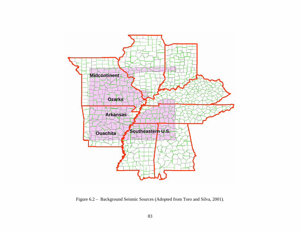
Southeastern U.S.
Midcontinent
Ozarks
Arkansas
Ouachita
Figure 6.2 – Background Seismic Sources (Adopted from Toro and Silva, 2001).
83

Figure 6.3 – Three Zones Used to Represent Wabash Seismic Zone (Adopted from Toro and Silva, 2001).
84

Figure 6.4 – Locations of parisons with the USGS 1996 hazard maps, Toro and Silva (2001) for a return period of 2500 years.
Bridge 12500 Year Return Period
0
0.51
1.52
2.53
3.5
PGA 0.2 Sec 1 Sec
USGS 1996
This StudyToro and Silva 2001
Bridge 22500 Year Return Period
0
0.5
1
1.5
2
2.5
3
3.5
PGA 0.2 Sec 1 Sec
USGS 1996
This StudyToro and Silva 2001
Bridge 32500 Year Return Period
0
0.51
1.52
2.53
3.5
PGA 0.2 Sec 1 Sec
USGS 1996
This StudyToro and Silva 2001
Bridge 42500 Year Return Period
0
0.51
1.52
2.53
3.5
PGA 0.2 Sec 1 Sec
USGS 1996
This StudyToro and Silva 2001
bridges studied and the corresponding 0.2-second, 1-second spectral accelerations, and PGA com
85

Bridge 11000 Year Return Period
00.20.40.60.8
11.21.41.61.8
PGA 0.2 Sec 1 Sec
USGS 1996
This Study
Bridge 21000 Year Return Period
PGA 0.2 Sec 1 Sec0
0.20.40.60.8
11.21.41.61.8
USGS 1996
This Study
Bridge 31000 Year Return Period
PGA 0.2 Sec 1 Sec0
0.20.40.60.8
11.21.41.61.8
USGS 1996
This Study
Bridge 41000 Year Return Period
00.20.40.60.8
11.21.41.61.8
PGA 0.2 Sec 1 Sec
USGS 1996
This Study
Figure 6.5 – Locations of bridges studied and the corresponding 0.2-second, 1-second spectral accelerations, and PGA comparisons with the USGS 1996 hazard maps for a return period of 1000 years.
86
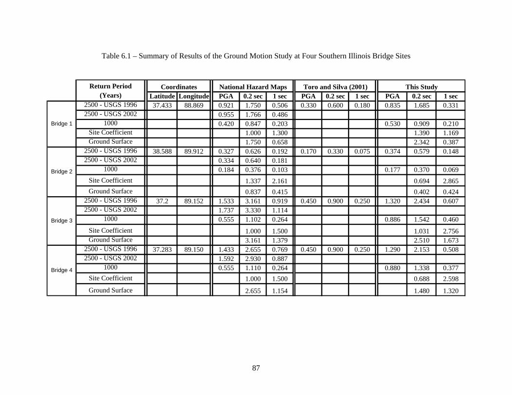
Table 6.1 – Summary of Results of the Ground Motion Study at Four Southern Illinois Bridge Sites
Return Period(Years) Latitude Longitude PGA 0.2 sec 1 sec PGA 0.2 sec 1 sec PGA 0.2 sec 1 sec
2500 - USGS 1996 37.433 88.869 0.921 1.750 0.506 0.330 0.600 0.180 0.835 1.685 0.3312500 - USGS 2002 0.955 1.766 0.486
1000 0.420 0.847 0.203 0.530 0.909 0.210Site Coefficient 1.000 1.300 1.390 1.169Ground Surface 1.750 0.658 2.342 0.387
2500 - USGS 1996 38.588 89.912 0.327 0.626 0.192 0.170 0.330 0.075 0.374 0.579 0.1482500 - USGS 2002 0.334 0.640 0.181
1000 0.184 0.376 0.103 0.177 0.370 0.069Site Coefficient 1.337 2.161 0.694 2.865Ground Surface 0.837 0.415 0.402 0.424
2500 - USGS 1996 37.2 89.152 1.533 3.161 0.919 0.450 0.900 0.250 1.320 2.434 0.6072500 - USGS 2002 1.737 3.330 1.114
1000 0.555 1.102 0.264 0.886 1.542 0.460Site Coefficient 1.000 1.500 1.031 2.756Ground Surface 3.161 1.379 2.510 1.673
2500 - USGS 1996 37.283 89.150 1.433 2.655 0.769 0.450 0.900 0.250 1.290 2.153 0.5082500 - USGS 2002 1.592 2.930 0.887
1000 0.555 1.110 0.264 0.880 1.338 0.377Site Coefficient 1.000 1.500 0.688 2.598
Ground Surface 2.655 1.154 1.480 1.320
Bridge 4
Bridge 2
Bridge 1
Bridge 3
Coordinates National Hazard Maps Toro and Silva (2001) This Study
87

7.1 Summary
The techn
Highway and Transportation Officials
(AASHTO 1996) and the
essentially the sam
the Applied Technology Council (ATC 1981).
Research Pr
highway bridges (NCHRP Project
LRFD bridge design specifications
for a stand-alone set of
Design of Highway Bridges” developed by a joint
Center for Earthquake Engineering Resear
objective of
research findings, design philosophies, and design approaches.
In com
adopted a dual-criteria strategy
Frequent Earthquak
bridge (with a return period
Considered
approxim
level earthq
years). Also, the proposed NCHRP Specification
term
88
7. SUMMARY AND CONCLUSIONS
ical basis of the seismic provisions within both the American Association of State
(AASHTO) Standard Specifications for Highway Bridges
AASHTO LRFD Bridge Design Specifications (AASHTO 1998) are
e as that of the seismic design guidelines published over two decades ago by
In 1998, the National Cooperative Highway
ogram initiated a study to develop a new set of seismic design provisions for
12-49) for possible incorporation into the future AASHTO
. The recommended specification provided the technical basis
provisions entitled “Recommended LRFD Guidelines for the Seismic
venture of the ATC and the Multidisciplinary
ch, MCEER (ATC/MCEER 2002). The primary
the Guidelines was to develop seismic design provisions that reflect the latest
parison with the AASHTO Specifications, the proposed NCHRP Specification has
of two-level design earthquakes. One based on an expected or
e (FE) with a 50% probability of exceedance in the 75-year design life of a
of 108 years), and the second based on a rare or Maximum
Earthquake (MCE) with a 3% probability of exceedance in 75 years (with an
ate return period of 2500 years). Current AASHTO Specifications consider a single-
uake with a 10% probability of exceedance in 50 years (with a return period of 475
defines two seismic performance levels in
ance of the bridge in the rare earthquake event: Life Safety –
w h means the bridge should not collapse (partial or complete replacement may be required)
and serious personal injury or loss of life should be avoided, and Operational – which means the
bridge will be functional immediately after a rare earthquake. New US Geological Survey
(USGS) maps developed by A.D. Frankel and E.V. Leyendecker (2000) are used in the proposed
s of the anticipated perform
hic

NCHRP Specification inste 1988 NEHRP provisions
sed in the current AASHTO specifications (AASHTO 1996 and 1998). The seismic design
the proposed NCHRP Specification is summarized in Chapter 2.
ccording to the current AASHTO Specifications, Division 1A, the Seismic Performance
ad of the USGS maps developed for the
u
procedure used in
As a part of a research project sponsored by Illinois Transportation Research Center (ITRC), the
substructures of four existing bridges in southern Illinois were redesigned according to the
proposed NCHRP Specification (ATC/MCEER 2002) and the AASHTO Specifications
(AASHTO 1996). The results of the design of first three bridges located in Johnson County, St.
Clair County, and Pulaski County are presented in Chapters 3, 4, and 5, respectively, where the
impact of using the new proposed NCHRP Specification on the materials and construction costs
are also included. The corresponding engineering computations are given in Appendices A
through F. The result of a similar study for the fourth bridge (currently in progress) will be
submitted to the project Technical Review Panel (TRP) as an addendum report due to
termination of the project effective June 30, 2004, as a result of both the appropriation and re-
appropriation of the ITRC not being included in the Illinois Department of Transportation
(IDOT) budget for FY 2005.
A
Category (SPC) of the Johnson County bridge (originally designed in 1970) and St. Clair County
bridge (originally designed in 2000) are specified as “B” where the Acceleration Coefficient (A)
of 0.15g and 0.1125g and Soil Profile Type of I and III, Site Coefficient (S) of 1.0 and 1.5 are
used, respectively. For the Pulaski County bridge (originally designed in 1965) with Site Soil
Profile Type III (S=1.5), the SPC of “C” is selected where A = 0.22g. It is noted that since the
St. Clair County bridge was recently designed according to the AASHTO Specification, its
substructure members were only checked for strength adequacy.
According to the proposed NCHRP Specification and with the provided geotechnical
information, the bridge sites in Johnson County, St. Clair County, and Pulaski County are
classified as Site Class “D” with Seismic Hazard Level of IV where Seismic Design and
Analysis Procedure (SDAP) “D” and Seismic Detailing Requirements (SDR) of 6 are used to
89

obtain the “Operational” performance objective. No potential for liquefaction exists at the given
sites.
For both AASHTO design and NCHRP design, the bridges are idealized as a “stick figure”
piers, and non-integral reinforced concrete abutments. The
undations consisted of concrete or steel piles. It is noted that for comparison purposes in all
s in southern Illinois was also
valuated in this study. The acceleration coefficients for both bedrock and ground surface levels
presented and compared with the USGS values in Chapter 7.
model using SAP 2000 beam elements (CSI 1998), where the stiffnesses and masses of the
members of the superstructure and substructure are converted into equivalent beam elements.
Cracked section properties are used for substructure elements. The foundation of the bridge is
modeled using springs, whose stiffnesses are calculated based on the pile stiffnesses. Note that
the foundation model requires iteration, since the piles are not designed initially and the spring
stiffnesses, and hence the finite element analysis, has to be updated throughout the design phase.
The structure is analyzed independently in both the longitudinal and transverse directions where
an adequate number of modes are included in each direction to obtain at least 90% mass
participation.
The substructures of these bridges consisted of interior bents comprised of reinforced concrete
solid walls or multi-column
fo
Illinois bridges investigated, similar earthquake resisting systems are used in the NCHRP design
as in the AASHTO design, as requested by the project TRP. The superstructures of these bridges
consisted of reinforced concrete slabs supported on two-, three-, and four-span continuous steel
wide flange beams or plate girders.
Since using the proposed NCHRP Specification can result in a significant increase in the level of
earthquake forces in southern Illinois (as opposed to the current AASHTO Specifications), the
realism of the new USGS accelerations for the four bridge site
e
were regenerated where at each bridge site by an independent procedure using existing source
paths and site models, and attenuation relationships supplemented by new developments to
produce synthetic time histories, response spectra values at frequencies of interest, uniform
hazard spectra, and site amplification factors. The ground motion acceleration results are
90

7.2 Observations and Concluding Remarks
AASHTO seismic forces are uniformly based on a “Life Safety” design philosophy. The
n forces and moments in substructure members in cases investigated, indicates that
e peak values of the spectrum are significantly higher (2.9 to 5.7 times) than the corresponding
RP design forces and moments for the substructure elements
nd foundations were significantly higher than the corresponding values used in AASHTO
NCHRP guidelines are based on a two-tier approach, allowing the bridge owners to choose a
“Life Safety” or an “Operational” level of performance, depending on how critical the roadway
is in terms of emergency response, economic recovery, and other intangible factors. In this
research, as requested by IDOT, the AASHTO Specifications were compared to an
“Operational” NCHRP performance level. Thus, it is expected that the seismic forces obtained
from the AASHTO Specifications in Illinois bridges would be lower than those obtained from
the proposed NCHRP Specification when this approach is used.
Comparison of the design earthquake response spectrum for the MCE, which governs the
NCHRP desig
th
values obtained from the AASHTO design earthquake response spectrum at the bridge sites
given in three southern Illinois counties (see Figures 3.2, 4.3, and 5.4). Also, the AASHTO
response modification factors for all bridges investigated were significantly larger (2.0 to 3.3
times) than the corresponding values used in the NCHRP designs for the MCE since the
“Operational” performance objective was specified for the NCHRP design.
Due to the above reasons, the NCH
a
Specifications (see Tables 3.1, 3.2, 4.1, 4.2, 5.1, and 5.2). Consequently, larger amounts of
reinforcing steel and/or concrete were used in the NCHRP wall or multi-column bents where an
extensive number of reinforced concrete or steel H piles were needed in the foundations in
comparison to the AASHTO design (see Figures 3.12, 3.13, 4.8, 4.9, 4.10, 5. 9, 5.10, and 5.11).
More specifically, the concrete volume and reinforcing steel weight required in the NCHRP
design are 3.16 and 2.39 times the corresponding values obtained using AASHTO Specifications
in the Johnson County bridge while it is estimated that the total cost of the interior bents
91

designed using the NCHRP Specification is 1.96 times the value obtained using the AASHTO
pecifications.
ing steel weight needed for the
bstructures designed according to the proposed NCHRP Specification are 4.88 and 5.61 times
stem and the foundation type when necessary.
is considered. Slightly lower acceleration coefficients were found in the study for the Bridges 1,
S
For the St. Clair County Bridge, the concrete volume and reinforcing steel weight needed for the
substructures designed according to the proposed NCHRP Specification are 3.65 and 4.30 times
the corresponding values obtained using AASHTO Specifications while it is observed that the
NCHRP substructure bent design cost is 5.23 times the corresponding value obtained in the
AASHTO design.
In the Pulaski County bridge, the concrete volume and reinforc
su
the corresponding values obtained using AASHTO Specifications while it is observed that the
NCHRP substructure bent design cost is 5.43 times the corresponding value obtained in the
AASHTO design. It is noted that the construction cost impact of using the proposed NCHRP
Specification is higher in the case of the Pulaski County bridge in comparison with the St. Clair
County bridge (5.43 vs 5.23) both with similar the AASHTO Site Soil Profile Type III and the
NCHRP Site Class of “D” while the product of the maximum spectrum acceleration coefficient
ratio of Samax (MCE) / Samax (AASHTO) and the response modification factor ratio of RAASHTO / R MCE
is also higher in the case of the Pulaski County bridge.
The size of the footings and number of piles needed for the NCHRP designed substructure in this
study are obviously impractical to actually incorporate into the final design plans. These were
shown for comparison of like foundation types. It is recommended that in practical design the
bridge engineer take advantage of the flexibility provided by the proposed NCHRP Specification
by using other methods of handling the increased seismic demand on the substructure such as the
use of seismic isolation bearings, seismic lock-up devices, or a change in the earthquake resisting
sy
Comparison of the ground motion accelerations obtained in this study with the ones obtained
from the USGS maps (1996) indicates that they are comparable when a 2500-year return period
92

3, and 4 and a slightly higher acceleration coefficient was found for Bridge 2 (see Figure 6.4 and
Table 6.1 for bridge locations and summary of the ground motion results).
7.3 Future Research
For further study of the impact of construction cost on southern Illinois highway bridges using the proposed NCHRP Specification, we propose that several additional cases be considered where the added flexibility provided in the proposed NCHRP Specifications is fully utilized by investigating more innovative methods of handling the increased seismic demands such as using
ad rubber seismic isolators (Arab et al. 2004); or changing the earthquake resisting systems
r of soil, is based on new research being onducted for the Mid-America Earthquake Center (MAEC). For future ground motion research
lesuch as using more flexible piers to reduce the seismic loads (by increasing the fundamental period of the bridge) or using integral abutments to resist the seismic loads where appropriate (Emami and Panahshahi 2004). Also, additional investigations can be conducted using the 1000-year seismic event as the MCE instead of the 2500-year event used in the proposed NCHRP Specifications. Future research using NCHRP “Life Safety” performance objective could also provide valuable information for cost impact study of nonessential Illinois bridges.
For the ground motion study of the southern Illinois region, another software packages named DEEPSOIL has been recently developed by Professor Hashash of the University of Illinois and his students (Hashash and Park, 2001; Hashash and Park, 2002). The software package DEEPSOIL, which considers the full nonlinear behaviocin southern Illinois, we propose further investigation is done using the computer package DEEPSOIL and compare the results with SHAKE91 results.
93
REFERENCES
American Association of State Highway and Transportation Officials. (1998). AASHTO LRFD
cifications, Second Editions.
American Association of State Highway and Transportation Officials. (1996). AASHTO
Recommended Lrfd Guidelines For The Seismic Design Of Highway Bridges Based On
Nchrp Project 12-49 Versus The Current Design Provisions For Two Existing Bridges”,
Simulating Ground Motions from
Earthquakes: Version 2.0 – A Revision of OFR 96-80-A.” USGS, Menlo Park.
Campbell, K.W. and Y. Bozorgnia (2003). “Updated near-source ground motion (attenuation)
relations for the horizontal and vertical components of peak ground Acceleration and
Acceleration Response Spectra.” Bull. Seism. Soc. Am., in press.
Capron, M.R., Friedland, I.M., and Mayes, R.L. (2001). “Seismic Design of Highway Bridges:
Recommended Specifications (Project ATC-49/NCHRP Project 12-49),” ASCE
Structures Congress, May, Washington DC.
CSI. (1998). Integrated Structural Analysis and Design – SAP2000 Nonlinear, Computers and
Structures, Inc., Berkeley, California.
Bridge Design Spe
Standard Specifications for Highway Bridges, Sixteenth Edition.
Applied Technology Council (ATC) (1981). “Design Guidelines for Highway Bridges,” ATC-6,
Palo Alto, CA.
Applied Technology Council (ATC) and Multidisciplinary Center for Earthquake Engineering
Research (MCEER) Joint Venture. (2002). “Recommended LRFD Guidelines for the
Seismic Design of Highway Bridges – Part I: Specifications, and Part II: Commentary
and Appendices,” ATC/MCCER, Washington, DC.
Arab, A., Siegfried, D., Darvish, J., and Anderson, R. (2004) “Evaluation Of The Impact Of
Proceedings of 4th National Seismic Conference and Workshop on Bridges, Memphis,
Tennessee, February.
Atkinson, G.M. and D.M. Boore. (1995). “Ground motions relations for eastern North America.”
Bull. of Seism. Soc. of Am., 85, pp. 17-30.
Boore, D.M. (2003). “SMSIM – Fortran Programs for
94

Earthquake Engineering Research (1990). Loma Prieta Earthquake
Reconnaissance Report, Earthquake Spectra, Special Supplement to Vol. 6, May, 448 pp.
Earthqu RI) (1995). Northridge Earthquake
Reconnaissance Report, Earthquake Spectra, Supplement C to Vol. 11, January, 278 pp.
Earthqu en Nanbu Earthquake,
January 17, 1995, EERI Preliminary Reconnaissance Report, February, 116 pp.
Emami, B., and Panahshahi, N. (2004) “A Comparison Study of Different Resisting Systems in
Seismic Design of Highway Bridges Using Proposed NCHRP Provisions,” Proceedings,
Franke ndeker, E.V., Dickman, N., Hanson,
S., and Hopper, M. (1996) “National Seismic Hazard Maps: Documentation,” U.S.G.S.
Franke
l Survey, Reston, VA, March.
Engineering Geology, 62(1-3), 185-206.
arthquake
Engineering, 22(7), pp. 611-624.
Idriss,
onmental Engineering,
University of California, Davis.
Park, D
and Workshop on Bridges and Highways,
February 9-12, Memphis, Tennessee.
Portlan PCACOL: Design and Investigation of Reinforced
Institute (EERI)
ake Engineering Research Institute (EE
ake Engineering Research Institute (EERI) (1995), The Hyogo-K
ASCE/SEI 2004 Structures Congress, American Society of Civil Engineers, Nashville,
TN, May 24-26.
l, A.D., Mueller, C., Barnhard, T., Perkins, D., Leye
Open File Report 96-532, Denver, CO, June.
l, A.D., and Leyendeker, E.V. (2000). Uniform Hazard Response Spectra and Seismic
Hazard Curves for the United States (CD-ROM), National Seismic Hazard Mapping
Project, U.S. Geologica
Hashash, Y.M.A. and D. Park. (2001). “Non-linear one-dimensional seismic ground motion
propagation in the Mississippi embayment.”
Hashash, Y. M. A. and D. Park. (2002). “Viscous damping formulation and high frequency
motion propagation in nonlinear site response analysis.” Soil Dynamics and E
I.M., and Sun, J.I. (1992). “SHAKE-91: Equivalent Linear Seismic Response Analysis of
Horizontally Layered Soil Deposits,” Department of Civil & Envir
., S. Pezeshk, and Y. Hashash. (2004). “Nonlinear site response of deep deposits in West
Tennessee.” 4th National Seismic Conference
d Cement Association (PCA) (1999),
95
Concrete Column Sections, PCA, Illinois.
, J. (2000). “Earthquake Engineering for Transportation Structures – Past, Present, and Penzien
Pezesh
t, Project
Reese, , Isenhower, W.M., Arrellaga, J.A., and Hendrix, J. (2000). A Program
Somerv es, and C. Saikia. (2001). “Ground motion
Toro, G el of strong ground motions from
Report, Prepared under USGS External Grant Number
1434-HQ-97-GR-02981.
USGS
Future,” EERI Distinguished Lecture.
k, S., Camp, C.V., Liu, L., Evans, Jr., J.M., and He, J. (1998). “Seismic Acceleration
Coefficients For West Tennessee and Expanded Scope of Work for Seismic Acceleration
Coefficients For West Tennessee Phase 2 - Field Investigation,” Final Repor
Number TNSPR-RES116, January, Prepared for the Tennessee Department of
Transportation and the U.S. Department of Transportation Federal Highway
Administration, 390 pages.
L.C., Wang, S.T.
for the Analysis of Piles and drilled Shafts under Lateral Loads – LPILE, ENSOFT, Inc.,
Austin, Texas.
ille, P., N. Collins, N. Abrahamson, R. Grav
attenuation relations for the central and eastern United States.” Final Report to U.S.
Geological Survey.
., N. Abrahamson, and J. Schneider. (1997). “Mod
earthquakes in the central and eastern North America: best estimates and uncertainties.”
Seism. Res. Letts., 68, pp. 41-57.
Toro, G.R. and W.J. Silva. (2001). “Scenario earthquakes for Saint Louis, MO, and Memphis,
TN, and seismic hazard maps for the central United States region including the effect of
site conditions.” Final Technical
(1996). http://geohazards.cr.usgs.gov/eq/html/intermaps.html.
Van Arsdale, R. and A. Johnston. (1999). “Geological and seismological setting of the New
t, Paducah, Kentucky--Final Report. Prepared for
Lockheed-Martin Utility Services, Available through NRC Public Documents Library,
Madrid seismic zone and the Wabash Valley Seismic zone.” Appendix A of Risk
Engineering, Inc. (1999), Rev. 3 to Updated Probabilistic Seismic Hazard Analysis for
the Paducah Gaseous Diffusion Plan
Accession Number 9905140175, docket no. 07007001.
96

Walsh, nd Houston, S.L. (2000). “The State of the
...........
K.D., Frechette, D.N., Houston, W.N., a
Practice for the Design of Groups of Laterally Loaded Drilled Shafts,” Transportation
Research Record, No. 1736, pp. 33-40.
Wei, B. and S. Pezeshk. (1990). “A Method to Estimate Shear Wave Velocity of Soils.”
Memphis Area Engineering Societies Conference, Memphis, TN, May.
................................................................................................................................................
97

JOB NO 044-0041
www.siue.edu
SIUE.• Edwardsville, IL 62026 (618) 650-2533 • Fax: (618) 650-2555
SUBJECT FILE
Evaluation of Comprehensive Seismic Design of Bridges (LRFD) in Illinois
TITLE:
Johnson County Bridge BY
BE DATE
01/24/03 CHECKED
DATE
Appendix A -- Detailed Computations for Seismic Analysis and Design of Johnson the County Bridge using Proposed NCHRP Specification
A-1

JOB NO 044-0041
www.siue.edu
SIUE.• Edwardsville, IL 62026 (618) 650-2533 • Fax: (618) 650-2555
SUBJECT FILE
Evaluation of Comprehensive Seismic Design of Bridges (LRFD) in Illinois
TITLE:
Johnson County Bridge BY
BE DATE
01/24/03 CHECKED
DATE
Table of Contents of Appendix-A
Design response spectrum A-3 Section properties of superstructure A-4 Dead load calculation A-8 Primary SAP2000 model with fixed supports A-9 Pile stiffness A-12 P-multiply method for the expansion bent A-13 P-multiply method for the fixed bent A-18 Periods of the bridge for MCE and FE A-21 Response modification factors A-22 Maximum Considered Earthquakes forces A-23 Frequent Earthquake forces A-24 Interaction diagram for the wall piers A-26 Longitudinal reinforcement design of piles at fixed bent A-27 Longitudinal reinforcement design of piles at expansion bent A-31 Transverse reinforcement design of piles at fixed bent A-33 Transverse reinforcement design of piles at expansion bent A-38 Connection reinforcement design of piles at expansion bent A-41 Connection reinforcement design of piles at fixed bent A-45 Shear design of the wall as a deep beam (fixed bent) A-50 Flexure design of the wall as a deep beam (fixed bent) A-52 Shear design of the wall as a deep beam (expansion bent) A-53 Flexure design of the wall as a deep beam (expansion bent) A-55 Transverse reinforcement design of wall at fixed bent A-57 Transverse reinforcement design of wall at expansion bent A-67 Connection design of wall to the pile cap at fixed bent A-78 Connection design of wall to the pile cap at expansion bent A-84 P-∆ requirements A-90 Minimum seat requirement A-91 Pile cap design A-92 Axial capacity design for the uplift A-101 Total settlement of the piles A-102
A-2
SDS Fa Ss⋅:=
SDS 1.75= Design earthquake response spectral acceleration at short period
SD1 Fv S1⋅:=
SD1 0.759= Design earthquake response spectral acceleration at long period
0.4 SDS⋅ 0.7=
TsSD1SDS
:= Period at the end of construction design spectral acceleration plateau
Ts 0.434= Sec
T0 0.2 Ts⋅:= Period at the beginning of construction design spectral acceleration plateau
T0 0.087= Sec
Fa Ss⋅ 1.75= > 0.6
Seismic Hazard Level IV (Guide Spec. Table 3.7-2)
SHEET NO __1__ 0F ____
JOB NO 044-0041
www.siue.edu
SIUE.• Edwardsville, IL 62026 (618) 650-2533 • Fax: (618) 650-2555
SUBJECT FILE
Evaluation of Comprehensive Seismic Design of Bridges (LRFD) in Illinois
TITLE:
Johnson County Bridge BY
BE DATE
02/18/03 CHECKED
DATE
Site Class = Medium Stiff Clay
Site Class D MCEER Guide Spec. 3.4.2.1
Type I per AASHTO Spec.
s 1.0:= AASHTO Table 3.5.1
A 0.15:= g
- Design Response Spectrum Development - MCE (MCEER Guide Spec. 3.4.1)
Ss 1.75:= 0.2- second period spectral acceleration
S1 0.5061:= 1- second period spectral acceleration
Fa 1:= Site coefficient for short period
Fv 1.5:= Site coefficient for long period
A-3

Fa_fe Ss_fe⋅ 0.165=
SecT0_fe 0.06=
Period at the beginning of construction design spectral acceleration plateauT0_fe 0.2 Ts_fe⋅:=
SecTs_fe 0.298=
Period at the end of construction design spectral acceleration plateau Ts_feSD1_feSDS_fe
:=
0.4 SDS_fe⋅ 0.066=
Design earthquake response spectral acceleration at long periodSD1_fe 0.049=
SD1_fe Fv_fe S1_fe⋅:=
Design earthquake response spectral acceleration at short periodSDS_fe 0.165=
SDS_fe Fa_fe Ss_fe⋅:=
Site coefficient for long periodFv_fe 2.4:=
Site coefficient for short period Fa_fe 1.6:=
1-second period spectral accelerationS1_fe 0.0205:=
0.2-second period spectral accelerationSs_fe 0.1033:=
- Design Response Spectrum Development - FE (MCEER Guide Spec. 3.4.1)
SHEET NO __2__ 0F ____
JOB NO 044-0041
www.siue.edu
SIUE.• Edwardsville, IL 62026 (618) 650-2533 • Fax: (618) 650-2555
SUBJECT FILE
Evaluation of Comprehensive Seismic Design of Bridges (LRFD) in Illinois
TITLE:
Johnson County Bridge BY
BE DATE
02/18/03 CHECKED
DATE
A-4

in3Sy 24.8:=
in4Iy 124:=
in3Sx 243:=
in4Ix 3270:=
Depth of the girdersindgirder 26.9:=
Area of the girdersin2Agirder 27.7:=
Length of the bridgeftLbridge 109.33:=
Rolled beam 27W94
Superstructure Section Properties
Fig 1. Design response spectrum (MCEER Guide Spec. Fig 3.4.1-1)
Response Spectrum
0
0.2
0.4
0.6
0.8
1
1.2
1.4
1.6
1.8
2
0 0.5 1 1.5 2 2.5 3
Period (Sec)
Res
pons
e Sp
ectra
l Acc
eler
atio
n (F
ract
ion
of g
)
MCE
D I-AFE
SHEET NO __3__ 0F ____
JOB NO 044-0041
www.siue.edu
SIUE.• Edwardsville, IL 62026 (618) 650-2533 • Fax: (618) 650-2555
SUBJECT FILE
Evaluation of Comprehensive Seismic Design of Bridges (LRFD) in Illinois
TITLE:
Johnson County Bridge BY
BE DATE
02/18/03 CHECKED
DATE
A-5

L3 8 12⋅ max .49 .5 .745⋅,( )+:=
L3 96.49= in
beffective min L1 L2, L3,( ):=
beffective 85.92= in Effective width of the slab in composite section
hslab 8:= in Thickness of the slab
Aslab bslabhslab
N⋅:=
Aslab 504= in2
Ix_slab bslabhslab
3
12 N⋅⋅:=
Ix_slab 2.688 103×= in4
Yslabhslab
2:=
SHEET NO __4__ 0F ____
JOB NO 044-0041
www.siue.edu
SIUE.• Edwardsville, IL 62026 (618) 650-2533 • Fax: (618) 650-2555
SUBJECT FILE
Evaluation of Comprehensive Seismic Design of Bridges (LRFD) in Illinois
TITLE:
Johnson County Bridge BY
BE DATE
02/18/03 CHECKED
DATE
6 girder at 7' 2"Slab thickness = 8"Hung = 1"
N 8:= Number of longitudinal reinforcements
hung 1:= in
bslab 42 12⋅:=
bslab 504= in
Effective width of the composite section (AASHTO LRFD 4.6.2.6.2)
L1 32124
⋅:= 1/4 of the span length
L1 96= in
L2 7.16 12⋅:= Girder spacing
L2 85.92= in
A-6

Sy_compIy_comp42 .5⋅ 12⋅
:=
in4Iy_comp 1.069 107×=
Iy_comp 6 Iy⋅ 2 Agirder⋅ 3.582 10.742+ 17.92
+( )⋅+ Iy_slab+:=
in4Iy_slab 1.067 107×=
Iy_slab hslabbslab
3
12 N⋅⋅:=
inrx 9.837=
rxIx_compAcomp
:=
in2Acomp 670.2=
Acomp Agirder 6⋅ Aslab+:=
in4Sx_comp 7.563 103×=
Sx_compIx_compYx_comp
:=
in4Ix_comp 6.485 104×=
Ix_comp 6 Ix⋅ Ix_slab+ 6 Agirder⋅dgirder
22 Yslab⋅+ hung+ Yx_comp−
⎛⎜⎝
⎞⎠
2
⋅+ Aslab Yslab Yx_comp−( )2⋅+:=
From topinYx_comp 8.575=
Yx_comp
Aslab Yslab⋅ 6Agirderdgirder
22 Yslab⋅+ hung+
⎛⎜⎝
⎞⎠
⋅+⎡⎢⎣
⎤⎥⎦
6Agirder Aslab+( ):=
inYslab 4=
SHEET NO __5__ 0F ____
JOB NO 044-0041
www.siue.edu
SIUE.• Edwardsville, IL 62026 (618) 650-2533 • Fax: (618) 650-2555
SUBJECT FILE
Evaluation of Comprehensive Seismic Design of Bridges (LRFD) in Illinois
TITLE:
Johnson County Bridge BY
BE DATE
02/18/03 CHECKED
DATE
A-7

Bar 5.2 Lbridge⋅ .15⋅:=
kipsWgirders 70.911=
Wgirders94
10006⋅ Lbridge⋅ 1.15⋅:=
kipsWslab 459.186=
Wslab 428 Lbridge⋅
12⋅ .15⋅:=
Mass Calculation
in3Sy_plastic 6.366 104×=
Sy_plastic Sy_comp 1.5⋅:=
in3Sx_plastic 1.134 104×=
Sx_plastic Sx_comp 1.5⋅:=
J 1.067 107×=
J bslabhslab
3
12 N⋅⋅ hslab
bslab3
12 N⋅⋅+:=
in2Ashear 536.16=
Ashear 0.8 Acomp⋅:=
inry 126.32=
ryIy_compAcomp
:=
in3Sy_comp 4.244 104×=
SHEET NO __6__ 0F ____
JOB NO 044-0041
www.siue.edu
SIUE.• Edwardsville, IL 62026 (618) 650-2533 • Fax: (618) 650-2555
SUBJECT FILE
Evaluation of Comprehensive Seismic Design of Bridges (LRFD) in Illinois
TITLE:
Johnson County Bridge BY
BE DATE
02/18/03 CHECKED
DATE
A-8

Fig 2. First Mode Shape (T=0.4902 Sec)
According to the section properties calculation, the finite element model of the bridge is completed by SAP2000. Figure 4 presents the finite element model of the bridge. In this model the bottom of wall piers are fixed and according to the base shears in this analysis, the final model contains springsat the bottom of walls.
kipsWpilecap 92.813=
Wpilecap 7.5 27.5⋅ 3⋅ .15⋅:=
klfwtotal 7.029=
wtotalWtotal109.33
:=
kipsWtotal 768.437=
Wtotal Wslab Wgirders+ Bar+ FWS+:=
Feature wearing surfacekipsFWS 153.062=
FWS35
100040⋅ Lbridge⋅:=
kipsBar 85.277=
SHEET NO __7__ 0F ____
JOB NO 044-0041
www.siue.edu
SIUE.• Edwardsville, IL 62026 (618) 650-2533 • Fax: (618) 650-2555
SUBJECT FILE
Evaluation of Comprehensive Seismic Design of Bridges (LRFD) in Illinois
TITLE:
Johnson County Bridge BY
BE DATE
02/18/03 CHECKED
DATE
A-9
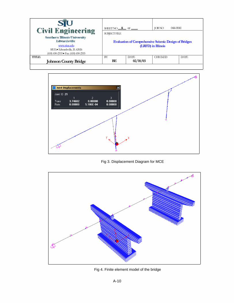
SHEET NO __8__ 0F ____
JOB NO 044-0041
www.siue.edu
SIUE.• Edwardsville, IL 62026 (618) 650-2533 • Fax: (618) 650-2555
SUBJECT FILE
Evaluation of Comprehensive Seismic Design of Bridges (LRFD) in Illinois
TITLE:
Johnson County Bridge BY
BE DATE
02/18/03 CHECKED
DATE
Fig 3. Displacement Diagram for MCE
Fig 4. Finite element model of the bridge
A-10

SHEET NO __9__ 0F ____
JOB NO 044-0041
www.siue.edu
SIUE.• Edwardsville, IL 62026 (618) 650-2533 • Fax: (618) 650-2555
SUBJECT FILE
Evaluation of Comprehensive Seismic Design of Bridges (LRFD) in Illinois
TITLE:
Johnson County Bridge BY
BE DATE
02/18/03 CHECKED
DATE
Table 1. Periods of the bridgeM O D A L P A R T I C I P A T I N G M A S S R A T I O S
MODE PERIOD INDIVIDUAL MODE (%)UX UY UZ
1 0.4902 67.52 0.00 0.002 0.1288 0.02 0.00 5.943 0.1245 8.80 0.00 0.004 0.0703 0.00 0.44 0.005 0.0692 0.01 0.00 0.006 0.0625 0.00 0.00 44.027 0.0555 0.00 62.10 0.008 0.0398 0.01 0.00 0.009 0.0362 0.00 13.44 0.0010 0.0262 2.29 0.00 0.0211 0.0228 0.00 0.00 7.3012 0.0223 0.62 0.00 0.3013 0.0219 0.08 0.00 0.0314 0.0215 0.27 0.00 0.2215 0.0186 2.60 0.00 0.0016 0.0184 0.00 0.00 0.0017 0.0135 0.00 2.54 0.0018 0.0134 0.00 0.00 0.2219 0.0132 0.00 0.00 8.24
100 0.0007 0.00 0.53 0.0099.54 99.07 98.21
With Fix Base
A-11

kft
Kaxial 9.767 104×=
(Guide Spec. 8.4.3.3)Kaxial AaxialEcL
⋅:=
Ec 5.184 105×=
ksfEc 3600 144⋅:=
ftL 37.5=
LLpile
12:=
ft2Aaxial 7.065=
Aaxial3.14
4⎛⎜⎝
⎞⎠
D2⋅:=
Area of longitudinal rebarAb 1:=
Number of rebar at each pile (expansion pier) Nexp 14:=
Number of rebar at each pile (fix pier) Nfix 18:=
Ratio of Es/Ecn 8:=
ft Diameter of the pilesD 3:=
Length of the pileinLpile 450:=
Spring Stiffness based on Design Example 8 and Transportation Research Record 1736 (State of Practice for Design of Group of Laterally Loaded Drilled Shafts).In this step, stiffness of the piles will be claculated based on P-multipliers curves with the coefficientsof FHWA.
SHEET NO __10__ 0F ____
JOB NO 044-0041
www.siue.edu
SIUE.• Edwardsville, IL 62026 (618) 650-2533 • Fax: (618) 650-2555
SUBJECT FILE
Evaluation of Comprehensive Seismic Design of Bridges (LRFD) in Illinois
TITLE:
Johnson County Bridge BY
BE DATE
02/18/03 CHECKED
DATE
A-12

SHEET NO __11__ 0F ____
JOB NO 044-0041
www.siue.edu
SIUE.• Edwardsville, IL 62026 (618) 650-2533 • Fax: (618) 650-2555
SUBJECT FILE
Evaluation of Comprehensive Seismic Design of Bridges (LRFD) in Illinois
TITLE:
Johnson County Bridge BY
BE DATE
02/18/03 CHECKED
DATE
Group pile stiffnessfor expansion bent
Fig 5. Pile group at the expansion bent
Fig 6. P-multipiler = 0.3 for the third row (shear vs. depth of the pile)
Fig 7. P-multipiler = 0.4 for the second row (shear vs. depth of the pile)
A-13

SHEET NO __12__ 0F ____
JOB NO 044-0041
www.siue.edu
SIUE.• Edwardsville, IL 62026 (618) 650-2533 • Fax: (618) 650-2555
SUBJECT FILE
Evaluation of Comprehensive Seismic Design of Bridges (LRFD) in Illinois
TITLE:
Johnson County Bridge BY
BE DATE
02/18/03 CHECKED
DATE
Fig 8. P-multipiler = 0.8 for the leading row (shear vs. depth of the pile)
0
50
100
150
200
250
300
350
400
0 0.5 1 1.5 2 2.5 3
P(0.8)P(0.4)P total
Fig 9. P-multiplier curve for longitudinal direction of bridge (displacement vs. shear)
0
100
200
300
400
500
600
0 0.5 1 1.5 2 2.5 3
P(0.8)P(0.4)P(0.3)P(total)
Fig 10. P-multiplier curve for transverse direction of bridge (displacement vs. shear)
A-14

kft
Npile 6:= Number of the piles
D 3:= ft
n 8:=
Nexp 14= Number of longitudinal reinforcement
Ab 1:=
Aaxial3.14
4⎛⎜⎝
⎞⎠
D2⋅ n 1−( )Nexp
Ab144⋅+:=
Aaxial 7.746= ft2
LLpile
12:=
L 37.5= ft
Ec 3600 144⋅:= ksf
Ec 5.184 105×=
SHEET NO __13__ 0F ____
JOB NO 044-0041
www.siue.edu
SIUE.• Edwardsville, IL 62026 (618) 650-2533 • Fax: (618) 650-2555
SUBJECT FILE
Evaluation of Comprehensive Seismic Design of Bridges (LRFD) in Illinois
TITLE:
Johnson County Bridge BY
BE DATE
02/18/03 CHECKED
DATE
∆x.28312
:= ∆x 0.024= ft Displacement of the pile cap in longitudinal direction
Fx 200:= kips Shear from Fig 9 for 0.283" displacement of the pile cap in longitudinal direction
nx 2:= Rows of piles in longitudinal direction
KpilexFx
∆x nx⋅:=
kftKpilex 4.24 103
×=
From Fig 10 and the 0.71" displacement of the pile cap in transverse direction (average of 3 pile)Kpiley 2366:=
kft
KpileKpilex Kpiley+( )
2:=
Kpile 3.303 103×=
A-15

kft
Kr_z 1.472 106×=
kft
Kr_y 7.806 107×=
kft
Kr_x 2.082 108×=
kft
Kaxial 6.424 105×=
kft
Ky_total 1.42 104×=
kft
Kx_total 2.544 104×=
Kr_z Kpile 6 4.52⋅ 4 92
⋅+( )⋅:=
Kr_x 4Kaxial 92⋅:=
Kr_y 6Kaxial 4.52⋅:=
Kaxial Npile Kaxial⋅:=
Ky_total Npile Kpiley⋅:=
Kx_total Npile Kpilex⋅:=
kft
Kaxial 1.071 105×=
Kaxial AaxialEcL
⋅:=
SHEET NO __14__ 0F ____
JOB NO 044-0041
www.siue.edu
SIUE.• Edwardsville, IL 62026 (618) 650-2533 • Fax: (618) 650-2555
SUBJECT FILE
Evaluation of Comprehensive Seismic Design of Bridges (LRFD) in Illinois
TITLE:
Johnson County Bridge BY
BE DATE
02/18/03 CHECKED
DATE
A-16
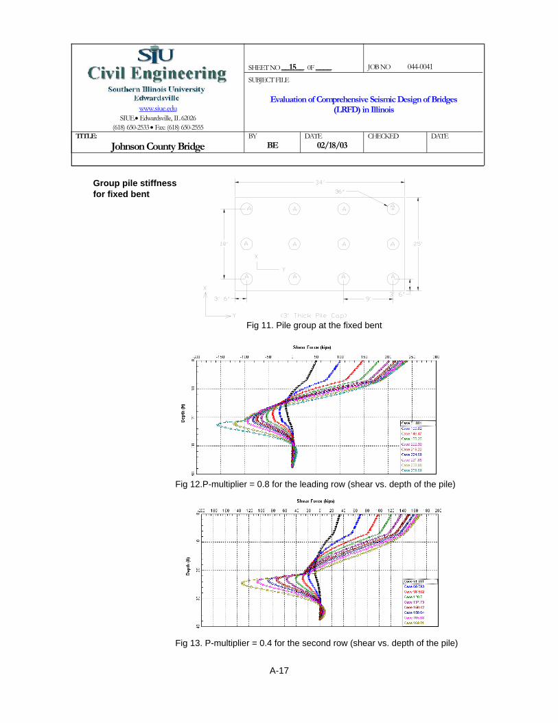
SHEET NO __15__ 0F ____
JOB NO 044-0041
www.siue.edu
SIUE.• Edwardsville, IL 62026 (618) 650-2533 • Fax: (618) 650-2555
SUBJECT FILE
Evaluation of Comprehensive Seismic Design of Bridges (LRFD) in Illinois
TITLE:
Johnson County Bridge BY
BE DATE
02/18/03 CHECKED
DATE
Group pile stiffnessfor fixed bent
Fig 11. Pile group at the fixed bent
Fig 12.P-multiplier = 0.8 for the leading row (shear vs. depth of the pile)
Fig 13. P-multiplier = 0.4 for the second row (shear vs. depth of the pile)
A-17

SHEET NO __16__ 0F ____
JOB NO 044-0041
www.siue.edu
SIUE.• Edwardsville, IL 62026 (618) 650-2533 • Fax: (618) 650-2555
SUBJECT FILE
Evaluation of Comprehensive Seismic Design of Bridges (LRFD) in Illinois
TITLE:
Johnson County Bridge BY
BE DATE
02/18/03 CHECKED
DATE
Fig 14. P-multiplier = 0.3 for the third row (shear vs. depth of the pile)
0
100
200
300
400
500
600
700
800
0 0.5 1 1.5 2 2.5 3
P(0.8)P(0.4)P(0.3)P(0.3)P(total)
Fig 15. P-multiplier curve for transverse direction of bridge (displacement vs. shear)
0
100
200
300
400
500
600
0 0.5 1 1.5 2 2.5 3
P(0.8)P(0.4)P(0.3)P(total)
Fig 16. P-multiplier curve for longitudinal direction of bridge (displacement vs. shear)
A-18

Kaxial AaxialEcL
⋅:=
Ec 5.184 105×=
ksfEc 3600 144⋅:=
ftL 37.5=
LLpile
12:=
ft2Aaxial 7.94=
Aaxial3.14
4⎛⎜⎝
⎞⎠
D2⋅ n 1−( )Nfix
Ab144⋅+:=
Ab 1:=
Nfix 18=
n 8:=
ft for the pilesD 3:=
Npile 12:=
kft
Kpile 2.025 103×=
KpileKpilex Kpiley+( )
2:=
kft
Kpiley 2380:=From Fig 15 and the 0.63" displacement of the pile cap in transverse direction (average of 4 pile)
kft
Kpilex 1670:=From Fig 16 and the 1.27" displacement of the pile cap in longitudinal direction (average of 3 pile)
SHEET NO __17__ 0F ____
JOB NO 044-0041
www.siue.edu
SIUE.• Edwardsville, IL 62026 (618) 650-2533 • Fax: (618) 650-2555
SUBJECT FILE
Evaluation of Comprehensive Seismic Design of Bridges (LRFD) in Illinois
TITLE:
Johnson County Bridge BY
BE DATE
02/18/03 CHECKED
DATE
A-19

kft
Kr_z 3.773 106×=
kft
Kr_y 8.535 108×=
kft
Kr_x 1.6 109×=
kft
Kaxial 1.317 106×=
kft
Ky_total 2.856 104×=
kft
Kx_total 2.004 104×=
Kr_z Kpile 8 92⋅ 6 13.52
⋅+ 6 4.52⋅+( )⋅:=
Kr_x 6 Kaxial⋅ 13.52 4.52+( )⋅:=
Kr_y 8Kaxial 92⋅:=
Kaxial Npile Kaxial⋅:=
Ky_total Npile Kpiley⋅:=
Kx_total Npile Kpilex⋅:=
kft
Kaxial 1.098 105×=
SHEET NO __18__ 0F ____
JOB NO 044-0041
www.siue.edu
SIUE.• Edwardsville, IL 62026 (618) 650-2533 • Fax: (618) 650-2555
SUBJECT FILE
Evaluation of Comprehensive Seismic Design of Bridges (LRFD) in Illinois
TITLE:
Johnson County Bridge BY
BE DATE
02/18/03 CHECKED
DATE
A-20

SHEET NO __19__ 0F ____
JOB NO 044-0041
www.siue.edu
SIUE.• Edwardsville, IL 62026 (618) 650-2533 • Fax: (618) 650-2555
SUBJECT FILE
Evaluation of Comprehensive Seismic Design of Bridges (LRFD) in Illinois
TITLE:
Johnson County Bridge BY
BE DATE
02/18/03 CHECKED
DATE
Table 2. Periods of the bridge: (a) MCE (b) FE
a( ) b( )M O D A L P A R T I C I P A T I N G M A S S R A T I O S
MODE PERIOD INDIVIDUAL MODE (%)UX UY UZ
1 0.4035 68.93 0.00 0.002 0.2898 0.00 22.88 0.003 0.2067 0.00 77.00 0.004 0.1683 18.24 0.00 0.005 0.1292 0.98 0.00 4.366 0.1133 6.83 0.00 0.547 0.0884 5.02 0.00 0.008 0.0687 0.00 0.00 0.259 0.0612 0.00 0.00 42.3210 0.0431 0.00 0.07 0.0011 0.0392 0.00 0.00 0.4512 0.0389 0.00 0.00 0.0013 0.0303 0.00 0.05 0.0014 0.0289 0.00 0.00 25.5115 0.0242 0.00 0.00 9.9216 0.0239 0.00 0.00 9.3517 0.0210 0.00 0.00 0.8118 0.0181 0.00 0.00 0.0919 0.0178 0.00 0.00 0.0020 0.0171 0.00 0.00 0.00
100.00 100.00 93.61
With Spring for the MCEM O D A L P A R T I C I P A T I N G M A S S R A T I O S
MODE PERIOD INDIVIDUAL MODE (%)UX UY UZ
1 0.4035 68.93 0.00 0.002 0.1683 18.24 0.00 0.003 0.1292 0.98 0.00 4.364 0.1133 6.83 0.00 0.545 0.1118 0.00 92.45 0.006 0.0884 5.02 0.00 0.007 0.0687 0.00 0.00 0.258 0.0612 0.00 0.00 42.329 0.0566 0.00 0.08 0.0010 0.0392 0.00 0.00 0.4511 0.0313 0.00 0.02 0.0012 0.0289 0.00 0.00 25.5113 0.0242 0.00 0.00 9.9214 0.0239 0.00 0.00 9.3515 0.0210 0.00 0.00 0.8116 0.0205 0.00 0.04 0.0017 0.0181 0.00 0.00 0.0918 0.0178 0.00 0.00 0.0019 0.0167 0.00 0.00 0.2620 0.0161 0.00 3.90 0.00
100.00 96.48 93.88
With Spring for the FE
A-21

Axialkips
486
534Fix Pier
Exp Pier
Dead Load
Location
1.371.01
0.90.80.8
Superstructure to abutmentColumn and pile to cap beam
Response Modification Factor (R) SDAP D Operational PerformanceSingle column
Vertical pileAll elements for FE
Wall pier
RFE 0.9:=
> 0.9RFE 0.926=
RFE 1 0.9 1−( )T
1.25 Ts⋅⎛⎜⎝
⎞⎠
+:=
Rwall 1=
Rwall 1 1 1−( )T
1.25 Ts⋅⎛⎜⎝
⎞⎠
+:=
< 1.5Rcol 1.372=
MCEER Guide Spec. 4.7Rcol 1 1.5 1−( )T
1.25 Ts⋅⎛⎜⎝
⎞⎠
⋅+:=
SecT .4035:=
SecTs 0.434=
1.51.01
0.90.80.8
Superstructure to abutmentColumn and pile to cap beam
Base Response Modification Factor (RB) SDAP D Operational PerformanceSingle column
Vertical pileAll elements for FE
Wall pier
MCEER Guide Spec. Table 4.7-1
SHEET NO __20__ 0F ____
JOB NO 044-0041
www.siue.edu
SIUE.• Edwardsville, IL 62026 (618) 650-2533 • Fax: (618) 650-2555
SUBJECT FILE
Evaluation of Comprehensive Seismic Design of Bridges (LRFD) in Illinois
TITLE:
Johnson County Bridge BY
BE DATE
02/18/03 CHECKED
DATE
A-22
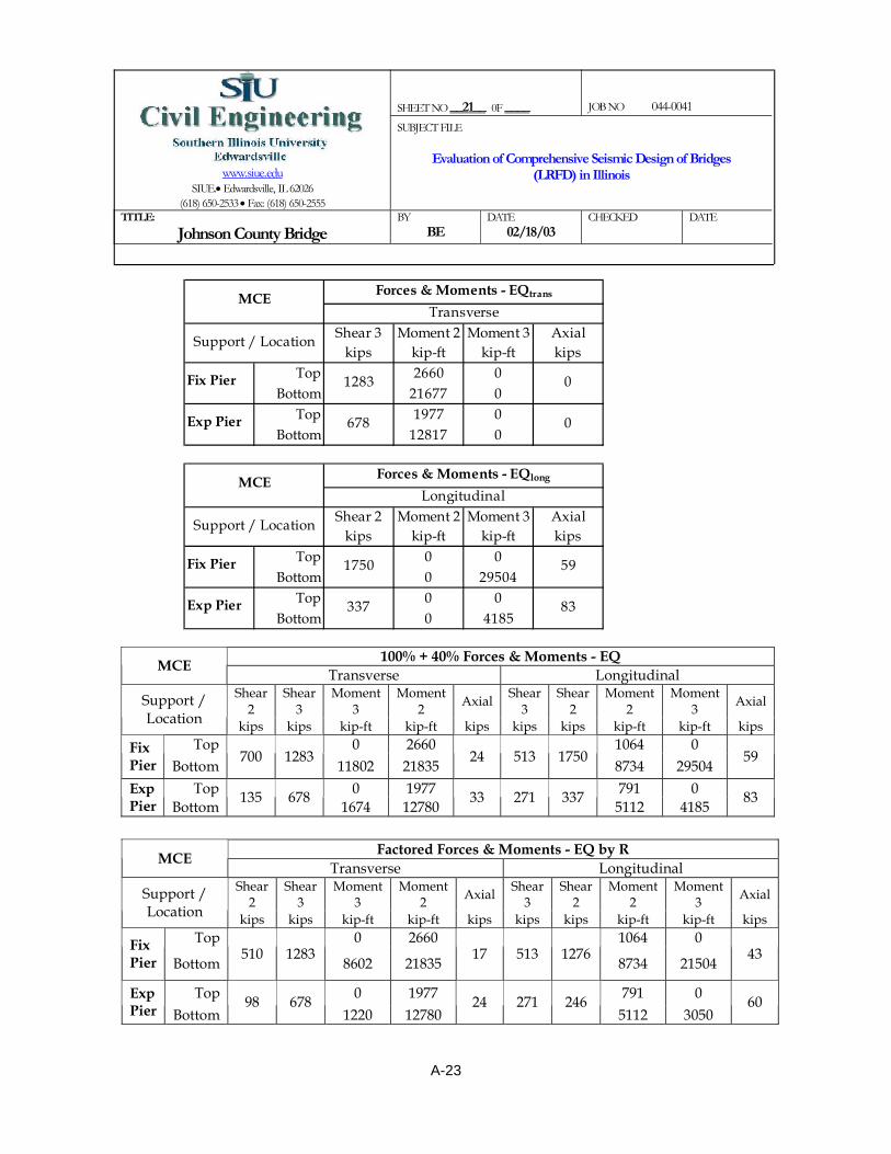
SHEET NO __21__ 0F ____
JOB NO 044-0041
www.siue.edu
SIUE.• Edwardsville, IL 62026 (618) 650-2533 • Fax: (618) 650-2555
SUBJECT FILE
Evaluation of Comprehensive Seismic Design of Bridges (LRFD) in Illinois
TITLE:
Johnson County Bridge BY
BE DATE
02/18/03 CHECKED
DATE
Shear 3 Moment 2 Moment 3 Axialkips kip-ft kip-ft kips
Top 2660 0Bottom 21677 0
Top 1977 0Bottom 12817 0
0
0Exp Pier
Support / Location
MCE Forces & Moments - EQtrans
1283
Transverse
Fix Pier
678
Shear 2 Moment 2 Moment 3 Axialkips kip-ft kip-ft kips
Top 0 0Bottom 0 29504
Top 0 0Bottom 0 4185
Longitudinal
1750 59
337 83
Fix Pier
Exp Pier
Forces & Moments - EQlong
Support / Location
MCE
100% + 40% Forces & Moments - EQ MCE Transverse Longitudinal Shear
2 Shear
3 Moment
3 Moment
2 Axial Shear 3
Shear 2
Moment 2
Moment 3 Axial Support /
Location kips kips kip-ft kip-ft kips kips kips kip-ft kip-ft kips Top 0 2660 1064 0 Fix
Pier Bottom 700 1283 11802 21835 24 513 1750 8734 29504 59
Top 0 1977 791 0 Exp Pier Bottom 135 678 1674 12780 33 271 337 5112 4185 83
Factored Forces & Moments - EQ by R MCE
Transverse Longitudinal Shear
2 Shear
3 Moment
3 Moment
2 Axial Shear 3
Shear 2
Moment 2
Moment 3 Axial Support /
Location kips kips kip-ft kip-ft kips kips kips kip-ft kip-ft kips Top 0 2660 1064 0 Fix
Pier Bottom 510 1283
8602 21835 17 513 1276
8734 21504 43
Top 0 1977 791 0 Exp Pier Bottom
98 678 1220 12780
24 271 246 5112 3050
60
A-23

SHEET NO __22__ 0F ____
JOB NO 044-0041
www.siue.edu
SIUE.• Edwardsville, IL 62026 (618) 650-2533 • Fax: (618) 650-2555
SUBJECT FILE
Evaluation of Comprehensive Seismic Design of Bridges (LRFD) in Illinois
TITLE:
Johnson County Bridge BY
BE DATE
02/18/03 CHECKED
DATE
Final Design Forces & Moments (EQ + DL) MCE Transverse Longitudinal Shear
2 Shear
3 Moment
3 Moment
2 Axial Shear 3
Shear 2
Moment 2
Moment 3 Axial Support /
Location kips kips kip-ft kip-ft kips kips kips kip-ft kip-ft kips
Top 0 2660 1064 0 Fix Pier Bottom 510 1283 8602 21835 551 513 1276 8734 21504 577
Top 0 1977 791 0 Exp Pier Bottom 98 678 1220 12780 510 271 246 5112 3050 546
Shear 3 Moment 2 Moment 3 Axialkips kip-ft kip-ft kips
Top 211 0Bottom 311 0
Top 140 0Bottom 470 0
Exp Pier
Support / Location
FE Forces & Moments - EQtrans
10
Transverse
Fix Pier
10
0
0
Shear 2 Moment 2 Moment 3 Axialkips kip-ft kip-ft kips
Top 0 0Bottom 0 2115
Top 0 0Bottom 0 395
Fix Pier
Exp Pier
Forces & Moments - EQlong
Support / Location
FELongitudinal
123 6
32 7
100% + 40% Forces & Moments - EQ FE Transverse Longitudinal
Shear 2
Shear 3
Moment 3
Moment 2 Axial Shear
3 Shear
2 Moment
2 Moment
3 Axial Support / Location
kips kips kip-ft kip-ft kips kips kips kip-ft kip-ft kips Top 0 211 84 0 Fix
Pier Bottom 49 10
846 311 2 4 123
124 2115 6
Top 0 140 56 0 Exp Pier Bottom
13 10 158 470
3 4 32 188 395
7
A-24

SHEET NO __23__ 0F ____
JOB NO 044-0041
www.siue.edu
SIUE.• Edwardsville, IL 62026 (618) 650-2533 • Fax: (618) 650-2555
SUBJECT FILE
Evaluation of Comprehensive Seismic Design of Bridges (LRFD) in Illinois
TITLE:
Johnson County Bridge BY
BE DATE
02/18/03 CHECKED
DATE
Factored Forces & Moments - EQ by R FE Transverse Longitudinal Shear
2 Shear
3 Moment
3 Moment
2 Axial Shear 3
Shear 2
Moment 2
Moment 3 Axial Support /
Location kips kips kip-ft kip-ft kips kips kips kip-ft kip-ft kips Top 0 234 94 0 Fix
Pier Bottom 55 11
940 346 3 4 137
138 2350 7
Top 0 156 62 0 Exp Pier Bottom
14 11 176 522
3 4 36 209 439
8
Final Design Forces & Moments (EQ + DL) FE
Transverse Longitudinal Shear
2 Shear
3 Moment
3 Moment
2 Axial Shear 3
Shear 2
Moment 2
Moment 3 Axial Support /
Location kips kips kip-ft kip-ft kips kips kips kip-ft kip-ft kips
Top 0 234 94 0 Fix Pier Bottom
55 11 940 346
537 4 137 138 2350
541
Top 0 156 62 0 Exp Pier Bottom
14 11 176 522
489 4 36 209 439
494
Longitudinal TransverseDirection (in) Direction (in)
Top 3.11 0.95Bottom Fix 1.16 0.77Bottom Exp 0.25 0.89Top 0.23 0.01Bottom Fix 0.03 0.02Bottom Exp 0.09 0.02
MCE
FE
Displacement
A-25
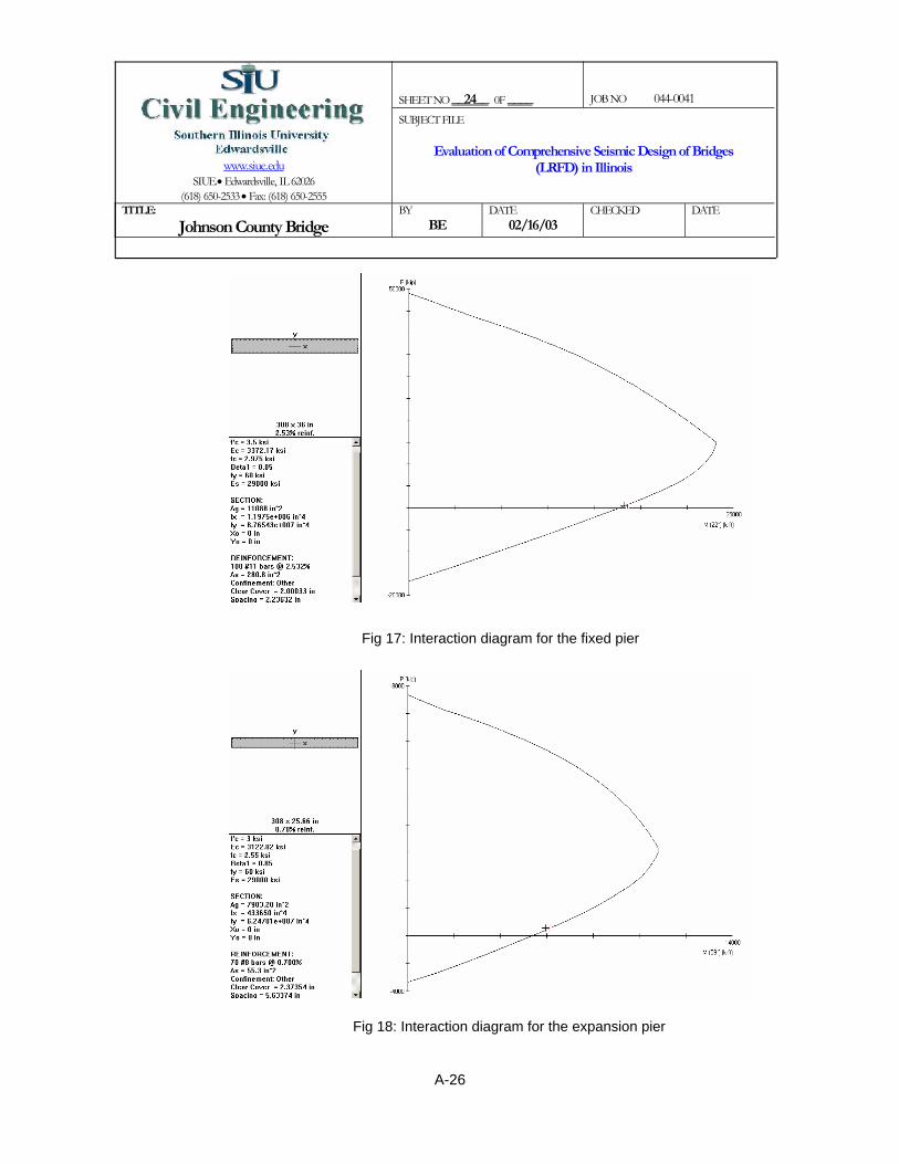
SHEET NO __24__ 0F ____
JOB NO 044-0041
www.siue.edu
SIUE.• Edwardsville, IL 62026 (618) 650-2533 • Fax: (618) 650-2555
SUBJECT FILE
Evaluation of Comprehensive Seismic Design of Bridges (LRFD) in Illinois
TITLE:
Johnson County Bridge BY
BE DATE
02/16/03 CHECKED
DATE
Fig 17: Interaction diagram for the fixed pier
Fig 18: Interaction diagram for the expansion pier
A-26

SHEET NO __25__ 0F ____
JOB NO 044-0041
www.siue.edu
SIUE.• Edwardsville, IL 62026 (618) 650-2533 • Fax: (618) 650-2555
SUBJECT FILE
Evaluation of Comprehensive Seismic Design of Bridges (LRFD) in Illinois
TITLE:
Johnson County Bridge BY
BE DATE
02/16/03 CHECKED
DATE
Fixed pierIn this step the maximum displacement of the top of the piles (from the SAP2000 model) are applied to the pile in L-pile program
∆ 1.2:= in displacement of the pile (includes the combination of 100% + 40%)
Fig 19. Displacement diagram of the pile
Fig 20. Shear diagram of the pile
A-27
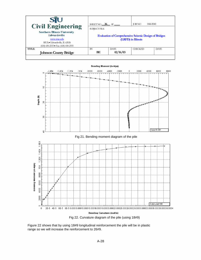
SHEET NO __26__ 0F ____
JOB NO 044-0041
www.siue.edu
SIUE.• Edwardsville, IL 62026 (618) 650-2533 • Fax: (618) 650-2555
SUBJECT FILE
Evaluation of Comprehensive Seismic Design of Bridges (LRFD) in Illinois
TITLE:
Johnson County Bridge BY
BE DATE
02/16/03 CHECKED
DATE
Fig 21. Bending moment diagram of the pile
Fig 22. Curvature diagram of the pile (using 18#9)
Figure 22 shows that by using 18#9 longitudinal reinforcement the pile will be in plastic range so we will increase the reinforcement to 26#9.
A-28

SHEET NO __27__ 0F ____
JOB NO 044-0041
www.siue.edu
SIUE.• Edwardsville, IL 62026 (618) 650-2533 • Fax: (618) 650-2555
SUBJECT FILE
Evaluation of Comprehensive Seismic Design of Bridges (LRFD) in Illinois
TITLE:
Johnson County Bridge BY
BE DATE
02/16/03 CHECKED
DATE
Fig 23. Curvature diagram of the pile (using 18#9)
Figure 23 indicates that by using 26#9 (2.5%) longitudinal reinforcement, pile will remain in elastic range under the MCE.
Fig 24 : Interaction diagram of the pile
A-29

SHEET NO __28__ 0F ____
JOB NO 044-0041
www.siue.edu
SIUE.• Edwardsville, IL 62026 (618) 650-2533 • Fax: (618) 650-2555
SUBJECT FILE
Evaluation of Comprehensive Seismic Design of Bridges (LRFD) in Illinois
TITLE:
Johnson County Bridge BY
BE DATE
02/16/03 CHECKED
DATE
Expansion pierIn this step the maximum displacement of the top of the piles (from the SAP2000 model) are applied to the pile in L-pile program
∆ .89:= in displacement of the pile (includes the combination of 100% + 40%)
Fig 25. Shear diagram of the pile
Fig 26. Bending moment diagram of the pile
A-30

SHEET NO __29__ 0F ____
JOB NO 044-0041
www.siue.edu
SIUE.• Edwardsville, IL 62026 (618) 650-2533 • Fax: (618) 650-2555
SUBJECT FILE
Evaluation of Comprehensive Seismic Design of Bridges (LRFD) in Illinois
TITLE:
Johnson County Bridge BY
BE DATE
02/16/03 CHECKED
DATE
Fig 27. Curvature diagram of the pile using 14 # 9 (1.38%)
Fig 28. Curvature diagram of the pile using 19 # 9 (1.87%)
Figure 28 shows that by using 14#9 longitudinal reinforcement the pile will remain in elastic range under the MCE.
A-31

SHEET NO __30__ 0F ____
JOB NO 044-0041
www.siue.edu
SIUE.• Edwardsville, IL 62026 (618) 650-2533 • Fax: (618) 650-2555
SUBJECT FILE
Evaluation of Comprehensive Seismic Design of Bridges (LRFD) in Illinois
TITLE:
Johnson County Bridge BY
BE DATE
02/16/03 CHECKED
DATE
Fig 29 : Interaction diagram of the pile
A-32

Dpp D 2 coverd5
2+
⎛⎜⎝
⎞⎠
−:= Spiral diameter
Dpp 32.375= in
L 37.5 12⋅:= Length of the pile
L 450= in
Ab 1:= in2 Longitudinal rebar diameter
Λ 2:= fixed - fixed fixity factor for circle section (MCEER Guide Spec. 8.8.2.3.a)
Pd 78:= kips Axial dead load of the pile
Per 0:= kips for earthquake effect in longitudinal direction
Ag3.14
4D2⋅:=
SHEET NO __31__ 0F ____
JOB NO 044-0041
www.siue.edu
SIUE.• Edwardsville, IL 62026 (618) 650-2533 • Fax: (618) 650-2555
SUBJECT FILE
Evaluation of Comprehensive Seismic Design of Bridges (LRFD) in Illinois
TITLE:
Johnson County Bridge BY
BE DATE
02/16/03 CHECKED
DATE
Pile transverse reinforcement (fix bent)
L=37.5' D=3' 26#9 ρ=2.5%
R 0.8:= Response modification factor for the connection (MCEER Guide Spec. Table 4.7-2)
εy .00207:=
D 36:= in Diameter of the pile
cover 1.5:= in Clear cover
d5 .625:= in Diameter of spirals
d9 1.128:= in Diameter of longitudinal reinforments
Dp D 2 cover d5+d9
2+
⎛⎜⎝
⎞⎠
⋅−:= Circle diameter of longitudinal reinforcement (see Design Example 8design step 8.2.1)
Dp 30.622= in
A-33

Av .8Ag:= Shear area of concrete
Av 813.888= in2
OS 1.5:= Over strength factor
φ .85:= for shear
α 25:= degree MCEER Guide Spec. 8.8.5.2
tanα .466:=
Hc 36:= in thickness of the pile cap
N 26:= number of rebars in pile
ρt NAb
Ag⋅:=
ρt 0.026=
SHEET NO __32__ 0F ____
JOB NO 044-0041
www.siue.edu
SIUE.• Edwardsville, IL 62026 (618) 650-2533 • Fax: (618) 650-2555
SUBJECT FILE
Evaluation of Comprehensive Seismic Design of Bridges (LRFD) in Illinois
TITLE:
Johnson County Bridge BY
BE DATE
02/16/03 CHECKED
DATE
Ag 1.017 103×= in2
Acc3.14
4Dpp
2⋅:= see Design Example 8 design step 8.2.3
Acc 822.79= in2
Kshape .32:= for circle section MCEER Guide Spec. 8.8.2.3.a
V 225:= kips Shear of the pile
fc 3500:= psi f'c of concrete
fyh 60:= ksi for steel
A-34

ksifyh 60=
Kshape 0.32=
kipsVs_rq 229.282=
Vs_rqVu
φVp Vc+( )−
⎡⎢⎣
⎤⎥⎦
:=
kipsVu 281.25=
VuVR
:=
kipsVc 97.354=
Vc 2 fc( )⎡⎣ ⎤⎦Acc
1000⋅:=
φ 0.85=
kipsVp 4.246=
The contribution due to arch actionVpΛ
2Pe⋅
Dp
L⋅:=
Effect dead load with the effect of upliftPe .8Pd:=
tanα 0.466=
Dp
L0.068=
inDp 30.622=
Dp 30.622=
inL 450=
Method 2: Explicit Approach MCEER Guide Spec. 8.8.2.3
SHEET NO __33__ 0F ____
JOB NO 044-0041
www.siue.edu
SIUE.• Edwardsville, IL 62026 (618) 650-2533 • Fax: (618) 650-2555
SUBJECT FILE
Evaluation of Comprehensive Seismic Design of Bridges (LRFD) in Illinois
TITLE:
Johnson County Bridge BY
BE DATE
02/16/03 CHECKED
DATE
A-35

OKkipsVs_rq 229.282=
kipsVs_pr 296.342=
Vs_pr3.14
2
Ash
s⋅ fyh⋅
Dpp
tanθ⋅:=
tanθ 0.532=
tanθ max tanθ .466,( ):=
tanθ 0.532=
tanθ 1.6 ρv_pr⋅Av
Λ ρt⋅ Ag⋅⋅
⎛⎜⎝
⎞
⎠
.25
:=
ρv_pr 3.192 10 3−×=
ρv_pr 2Ash
s Dpp⋅:=
#5in2Ash .31:=
< 6 Maximum spacing (NCHRP 5.10.6.2) OKins 6:=
ρt 0.026=
in2Av 813.888=
ksifsu 90=
fsu 1.5 fyh⋅:=
SHEET NO __34__ 0F ____
JOB NO 044-0041
www.siue.edu
SIUE.• Edwardsville, IL 62026 (618) 650-2533 • Fax: (618) 650-2555
SUBJECT FILE
Evaluation of Comprehensive Seismic Design of Bridges (LRFD) in Illinois
TITLE:
Johnson County Bridge BY
BE DATE
02/16/03 CHECKED
DATE
A-36

Summery of transverse reinforcementUse #5@6" spiral
ρv_pr
ρv_rq_nonplastic0.458=
< Method 2, use Method 2insmethod1 2.748=
smethod1 2Ash_method1
Dpp ρv_rq_nonplastic⋅⋅:=
Ash_method1 .31:=
ρv_pr 3.192 10 3−×=
ρv_rq_nonplastic 6.968 10 3−×=
ρv_rq_nonplastic ρv_rq 2fc
1000fyh−:=
ρv_rq 8.94 10 3−×=
ρv_rq Kshape Λ⋅ρt
φ⋅
fsufyh⋅
Ag
Av⋅ tanα⋅ tanθ⋅:=
in2Ash 0.31=
ins 6=
Method 1: Implicit Shear Detailing Approach MCEER Guide Spec.8.8.2.3
SHEET NO __35__ 0F ____
JOB NO 044-0041
www.siue.edu
SIUE.• Edwardsville, IL 62026 (618) 650-2533 • Fax: (618) 650-2555
SUBJECT FILE
Evaluation of Comprehensive Seismic Design of Bridges (LRFD) in Illinois
TITLE:
Johnson County Bridge BY
BE DATE
02/16/03 CHECKED
DATE
A-37

ρt 0.019=
ρt NAb
Ag⋅:=
number of rebars in pileN 19:=
kipsV 190:=
inDpp 32.5=
Dpp D 2 coverd4
2+
⎛⎜⎝
⎞⎠
−:=
inDp 30.872=
Dp D 2 cover d4+d9
2+
⎛⎜⎝
⎞⎠
⋅−:=
ind9 1.128:=
ind4 .5:=
Pile transverse reinforcement (expansion bent)
L=37.5' D=3' 19#9 ρ=1.87%
SHEET NO __36__ 0F ____
JOB NO 044-0041
www.siue.edu
SIUE.• Edwardsville, IL 62026 (618) 650-2533 • Fax: (618) 650-2555
SUBJECT FILE
Evaluation of Comprehensive Seismic Design of Bridges (LRFD) in Illinois
TITLE:
Johnson County Bridge BY
BE DATE
02/16/03 CHECKED
DATE
A-38
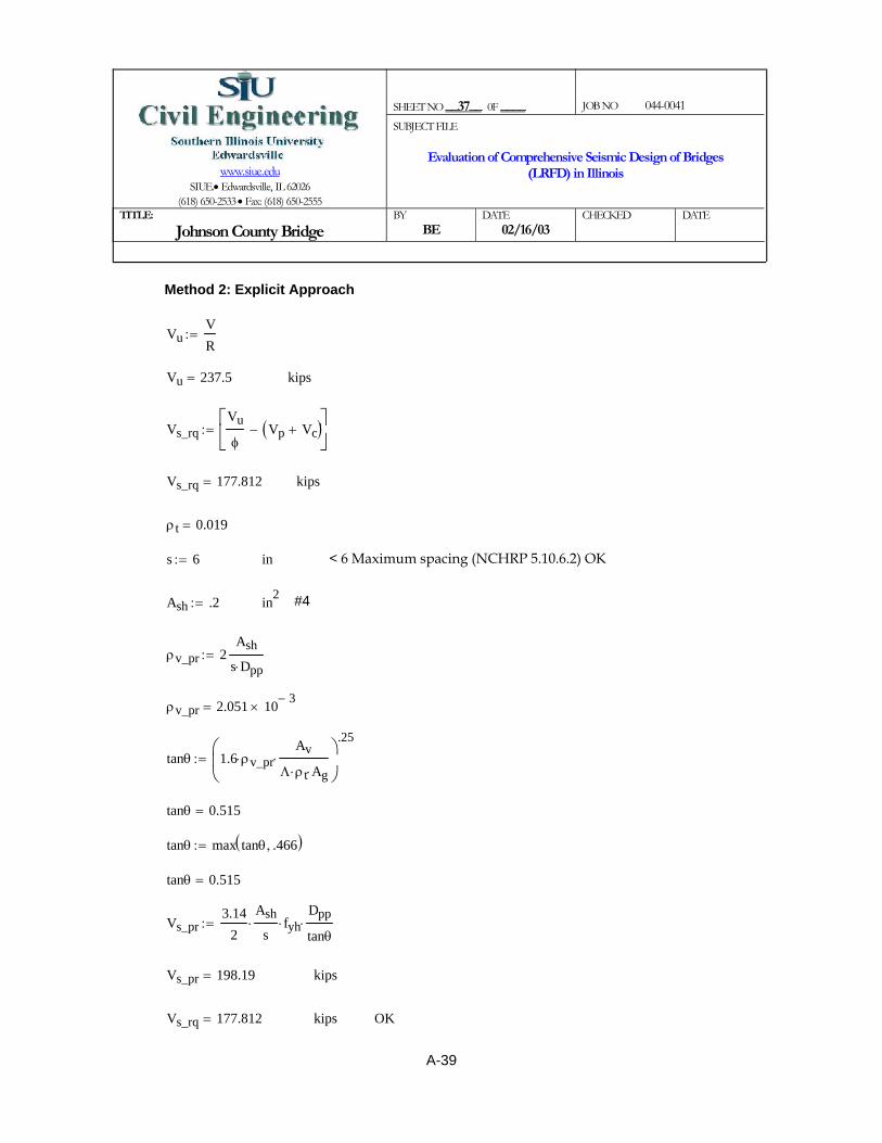
OKkipsVs_rq 177.812=
kipsVs_pr 198.19=
Vs_pr3.14
2
Ash
s⋅ fyh⋅
Dpp
tanθ⋅:=
tanθ 0.515=
tanθ max tanθ .466,( ):=
tanθ 0.515=
tanθ 1.6 ρv_pr⋅Av
Λ ρt⋅ Ag⋅⋅
⎛⎜⎝
⎞
⎠
.25
:=
ρv_pr 2.051 10 3−×=
ρv_pr 2Ash
s Dpp⋅:=
#4in2Ash .2:=
< 6 Maximum spacing (NCHRP 5.10.6.2) OKins 6:=
ρt 0.019=
kipsVs_rq 177.812=
Vs_rqVu
φVp Vc+( )−
⎡⎢⎣
⎤⎥⎦
:=
kipsVu 237.5=
VuVR
:=
Method 2: Explicit Approach
SHEET NO __37__ 0F ____
JOB NO 044-0041
www.siue.edu
SIUE.• Edwardsville, IL 62026 (618) 650-2533 • Fax: (618) 650-2555
SUBJECT FILE
Evaluation of Comprehensive Seismic Design of Bridges (LRFD) in Illinois
TITLE:
Johnson County Bridge BY
BE DATE
02/16/03 CHECKED
DATE
A-39

Summery of transverse reinforcement Use #4@6" spiral
ρv_pr
ρv_rq_nonplastic0.471=
< Method 2, use Method 2insmethod1 2.826=
smethod1 2Ash_method1
Dpp ρv_rq_nonplastic⋅⋅:=
Ash_method1 .2:=
ρv_pr 2.051 10 3−×=
ρv_rq_nonplastic 4.354 10 3−×=
ρv_rq_nonplastic ρv_rq 2fc
1000fyh−:=
ρv_rq 6.326 10 3−×=
ρv_rq Kshape Λ⋅ρt
φ⋅
fsufyh⋅
Ag
Av⋅ tanα⋅ tanθ⋅:=
#4in2Ash 0.2=
ins 6=
Method 1: Implicit Shear Detailing Approach
SHEET NO __38__ 0F ____
JOB NO 044-0041
www.siue.edu
SIUE.• Edwardsville, IL 62026 (618) 650-2533 • Fax: (618) 650-2555
SUBJECT FILE
Evaluation of Comprehensive Seismic Design of Bridges (LRFD) in Illinois
TITLE:
Johnson County Bridge BY
BE DATE
02/16/03 CHECKED
DATE
A-40

psifc 3.5 103×=
fsu 1.5 fyh⋅:=
ksifyh 60=
in2Av 813.888=
in2Ag 1.017 103×=
φ 0.85=
inDpp 32.5=
inDp 30.872=
kipsPd 78=
fixed - fixedΛ 2=
Longitudinal rebar diameterin2Ab 1=
L 450=
ρt 0.019=
inD 36=
εy 2.07 10 3−×=
R 0.8=
inHc 36=
Joint transverse reinforcement for the expansion bent
L=37.5' D=3' 19#9 ρ=1.87%
SHEET NO __39__ 0F ____
JOB NO 044-0041
www.siue.edu
SIUE.• Edwardsville, IL 62026 (618) 650-2533 • Fax: (618) 650-2555
SUBJECT FILE
Evaluation of Comprehensive Seismic Design of Bridges (LRFD) in Illinois
TITLE:
Johnson County Bridge BY
BE DATE
02/16/03 CHECKED
DATE
A-41
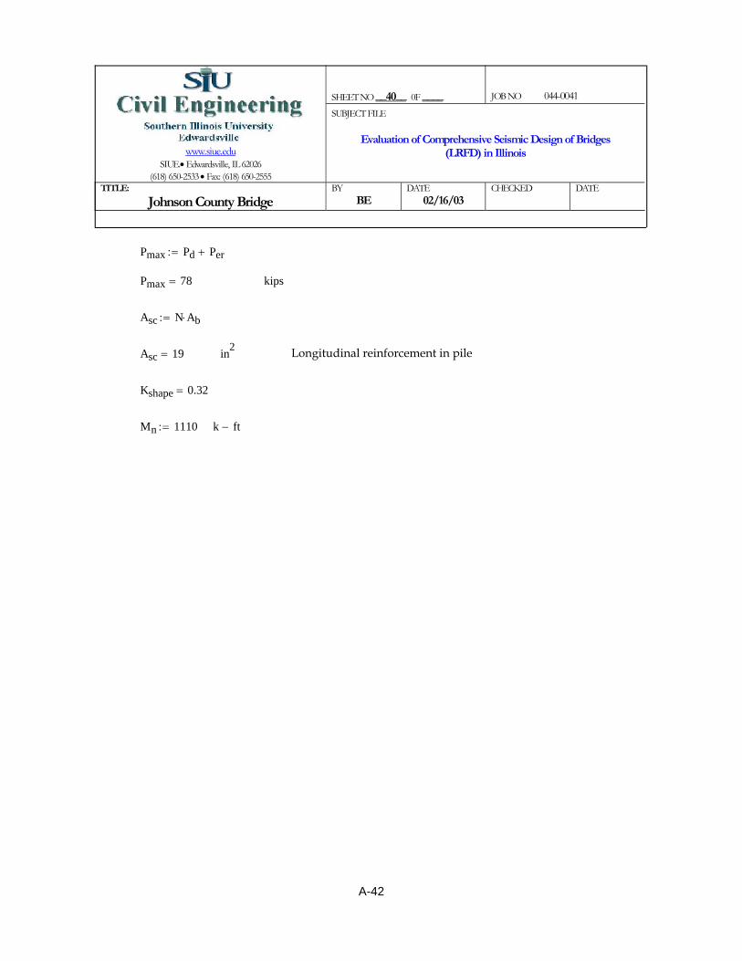
SHEET NO __40__ 0F ____
JOB NO 044-0041
www.siue.edu
SIUE.• Edwardsville, IL 62026 (618) 650-2533 • Fax: (618) 650-2555
SUBJECT FILE
Evaluation of Comprehensive Seismic Design of Bridges (LRFD) in Illinois
TITLE:
Johnson County Bridge BY
BE DATE
02/16/03 CHECKED
DATE
Pmax Pd Per+:=
Pmax 78= kips
Asc N Ab⋅:=
Asc 19= in2 Longitudinal reinforcement in pile
Kshape 0.32=
Mn 1110:= k ft−
A-42

bje 2 D⋅:=
inhc 36=
hc D:=
inhb 36=
hb Hc:=
ksifv 7.222 10 3−×=
fvPmax
Amid:=
in2Amid 1.08 104×=
Amid bb Lmid_dept_jt⋅:=
inLmid_dept_jt 72=
Lmid_dept_jt D Hc+:=
inD 36=
inbb 12.5 12⋅:=
k ft−Mp 1.665 103×=
k ft−Mn 1.11 103×=
OS 1.5=
Mp OS Mn⋅:=
kipsPmax 78=
fh 0:=
Explicit approach for joint design
SHEET NO __41__ 0F ____
JOB NO 044-0041
www.siue.edu
SIUE.• Edwardsville, IL 62026 (618) 650-2533 • Fax: (618) 650-2555
SUBJECT FILE
Evaluation of Comprehensive Seismic Design of Bridges (LRFD) in Illinois
TITLE:
Johnson County Bridge BY
BE DATE
02/16/03 CHECKED
DATE
A-43

Use #4@6"smax 7.133=
smax 4Ash
Dpp ρs_min⋅⋅:=
Ash .2:=
OKρs_min 3.451 10 3−×=
ρs_min3.5
1000
fcfyh⋅:=
OK, No extra reinforcement is necessarypc_max 0.875=
pc_max.25
1000fc⋅:=
pc 0.206=
pcfh fv+( )
2
fh fv−( )2
⎡⎢⎣
⎤⎥⎦
2
vhv2
++:=
OK, No extra reinforcement is necessarypt_max 0.207=
pt_max3.5
1000fc⋅:=
pt 0.198−=
ptfh fv+( )
2
fh fv−( )2
⎡⎢⎣
⎤⎥⎦
2
vhv2
+−:=
ksivhv 0.202=
vhvMn 12⋅
hb hc⋅ bje⋅:=
inbje 50.912=
SHEET NO __42__ 0F ____
JOB NO 044-0041
www.siue.edu
SIUE.• Edwardsville, IL 62026 (618) 650-2533 • Fax: (618) 650-2555
SUBJECT FILE
Evaluation of Comprehensive Seismic Design of Bridges (LRFD) in Illinois
TITLE:
Johnson County Bridge BY
BE DATE
02/16/03 CHECKED
DATE
A-44

psifc 3.5 103×=
fsu 1.5 fyh⋅:=
ksifyh 60=
in2Av 813.888=
in2Ag 1.017 103×=
φ 0.85=
inDpp 32.5=
inDp 30.872=
kipsPd 78=
fixed - fixedΛ 2=
Longitudinal rebar diameterin2Ab 1=
L 450=
ρt .0255:=
inD 36=
εy 2.07 10 3−×=
R 0.8=
inHc 36=
Joint transverse reinforcement for the fixed bent
L=37.5' D=3' 26#9 ρ=2.5%
SHEET NO __43__ 0F ____
JOB NO 044-0041
www.siue.edu
SIUE.• Edwardsville, IL 62026 (618) 650-2533 • Fax: (618) 650-2555
SUBJECT FILE
Evaluation of Comprehensive Seismic Design of Bridges (LRFD) in Illinois
TITLE:
Johnson County Bridge BY
BE DATE
02/16/03 CHECKED
DATE
A-45

SHEET NO __44__ 0F ____
JOB NO 044-0041
www.siue.edu
SIUE.• Edwardsville, IL 62026 (618) 650-2533 • Fax: (618) 650-2555
SUBJECT FILE
Evaluation of Comprehensive Seismic Design of Bridges (LRFD) in Illinois
TITLE:
Johnson County Bridge BY
BE DATE
02/16/03 CHECKED
DATE
Pmax Pd Per+:=
Pmax 78= kips
N 26:=
Asc N Ab⋅:=
Asc 26= in2 Longitudinal reinforcement in pile
Kshape 0.32=
Mn 1340:= k ft−
A-46

bje 2 D⋅:=
inhc 36=
hc D:=
inhb 36=
hb Hc:=
ksifv 7.222 10 3−×=
fvPmax
Amid:=
in2Amid 1.08 104×=
Amid bb Lmid_dept_jt⋅:=
inLmid_dept_jt 72=
Lmid_dept_jt D Hc+:=
inD 36=
inbb 12.5 12⋅:=
k ft−Mp 2.01 103×=
k ft−Mn 1.34 103×=
OS 1.5=
Mp OS Mn⋅:=
kipsPmax 78=
fh 0:=
Explicit approach for joint design
SHEET NO __45__ 0F ____
JOB NO 044-0041
www.siue.edu
SIUE.• Edwardsville, IL 62026 (618) 650-2533 • Fax: (618) 650-2555
SUBJECT FILE
Evaluation of Comprehensive Seismic Design of Bridges (LRFD) in Illinois
TITLE:
Johnson County Bridge BY
BE DATE
02/16/03 CHECKED
DATE
A-47

Aclamp 2.08=
Vertical reinforcement (Clamping reinforcement) (Guide Spec. 8.8.4.3.2)Aclamp .08 Asc⋅:=
7#5 vertical legs in (development length) each sideAjv
.3113.419=
Use #5
in2Ajv 4.16=
Vertical reinforcement (Stirrups) (Guide Spec. 8.8.4.3.2)Ajv .16Asc:=
OKpc_max 0.875=
pc_max.25
1000fc⋅:=
pc 0.247=
pcfh fv+( )
2
fh fv−( )2
⎡⎢⎣
⎤⎥⎦
2
vhv2
++:=
Extra reinforcement is requiredpt_max 0.207=
pt_max3.5
1000fc⋅:=
pt 0.24−=
ptfh fv+( )
2
fh fv−( )2
⎡⎢⎣
⎤⎥⎦
2
vhv2
+−:=
ksivhv 0.244=
vhvMn 12⋅
hb hc⋅ bje⋅:=
inbje 50.912=
SHEET NO __46__ 0F ____
JOB NO 044-0041
www.siue.edu
SIUE.• Edwardsville, IL 62026 (618) 650-2533 • Fax: (618) 650-2555
SUBJECT FILE
Evaluation of Comprehensive Seismic Design of Bridges (LRFD) in Illinois
TITLE:
Johnson County Bridge BY
BE DATE
02/16/03 CHECKED
DATE
A-48

Use #[email protected] 3.751=
smax2 Ash⋅
Dpp ρs⋅:=
ins 6=
in2Ash .31:=
OKρs_min 3.451 10 3−×=
Minimum required horizontal reinforcement (Guide Spec. 8.8.4.2.ρs_min3.5
1000
fcfyh⋅:=
ρs 5.086 10 3−×=
Hoops (Guide Spec. 8.8.4.3.4)ρs .4Asc
ld92
:=
.4 1.41⋅ fyh⋅ 33.84=
inld9 45.221=
ld9 1.25 1.128⋅fyh
fc1000
⋅:=
3#8 in 40" length each sideAh 2.633=
Horizontal reinforcement (Guide Spec. 8.8.4.3.3)Ah 0.08Asc
.79⋅:=
inld8 20.205=
in0.3 1.128⋅ fyh⋅ 20.304=
Development length for #9 (AASHTO LRFD 5.11.2.2.1-1)ld8 .63 1⋅fyh
fc1000
⋅:=
7#5 in 36" of the jointAclamp
.316.71=
SHEET NO __46-2__ 0F ____
JOB NO 044-0041
www.siue.edu
SIUE.• Edwardsville, IL 62026 (618) 650-2533 • Fax: (618) 650-2555
SUBJECT FILE
Evaluation of Comprehensive Seismic Design of Bridges (LRFD) in Illinois
TITLE:
Johnson County Bridge BY
BE DATE
02/16/03 CHECKED
DATE
A-49

A2 3.5 2.5MV d⋅⋅−:=
A1 0.73=
A1MV d⋅
:=
ΦVnkipsΦ 8 fc⋅ b⋅ d⋅1441000⋅⎛⎜
⎝⎞⎠
⋅ 4.014 103×=
k ft−M 21504:=
kipsV 1276:=
for shearΦ 0.85:=
<5 so design antology applys ld
0.769=
ftl 17.75:=
ftd 23.094=
d .9 h⋅:=
ftb 3:=
fth 25.66:=
psify 60000:=
psifc 3500:=
Shear design (fixed pier)
Deep beam design (Source: Reinforcement concrete, Nawy, 3rd edition, section 6.9)
SHEET NO __47__ 0F ____
JOB NO 044-0041
www.siue.edu
SIUE.• Edwardsville, IL 62026 (618) 650-2533 • Fax: (618) 650-2555
SUBJECT FILE
Evaluation of Comprehensive Seismic Design of Bridges (LRFD) in Illinois
TITLE:
Johnson County Bridge BY
BE DATE
02/16/03 CHECKED
DATE
A-50

SHEET NO __48__ 0F ____
JOB NO 044-0041
www.siue.edu
SIUE.• Edwardsville, IL 62026 (618) 650-2533 • Fax: (618) 650-2555
SUBJECT FILE
Evaluation of Comprehensive Seismic Design of Bridges (LRFD) in Illinois
TITLE:
Johnson County Bridge BY
BE DATE
02/16/03 CHECKED
DATE
A2 1.676= A2 < 3.5 OK
ρ .0253:=
Vc A2 1.9 fc⋅ 2500 ρ⋅V d⋅M
⋅+⎛⎜⎝
⎞⎠
⋅ b⋅ d⋅1441000⋅:=
Vc 3.328 103×= kips
Vcmax 6 fc⋅ b⋅ d⋅1441000⋅:=
Vcmax 3.541 103×= < Vc (controls)
Vc Vcmax:=
Vc 3.541 103×= kips
VsVΦ
Φ Vc⋅−:=
Vs 1.509− 103×= Shear reinforcement is not required
A-51

< 274.56 in2 OKin2Asmin 33.255=
Asmin max 3fc
fy⋅ b⋅ d⋅ 144⋅ 200 b⋅
d 144⋅
fy⋅,
⎛⎜⎝
⎞
⎠:=
< 274.56 in2 OKin2As 134.61=
AsM 12000⋅
Φ b⋅ fy⋅ j⋅ d⋅:=
ftj d⋅ 10.65=
j 0.461=
j.6 l( )
d:=
< 1 so jd=0.6llh
0.692=
k ft−M 2.15 104×=
Φ 1:=
Flexure design for deep beam
SHEET NO __49__ 0F ____
JOB NO 044-0041
www.siue.edu
SIUE.• Edwardsville, IL 62026 (618) 650-2533 • Fax: (618) 650-2555
SUBJECT FILE
Evaluation of Comprehensive Seismic Design of Bridges (LRFD) in Illinois
TITLE:
Johnson County Bridge BY
BE DATE
02/16/03 CHECKED
DATE
A-52
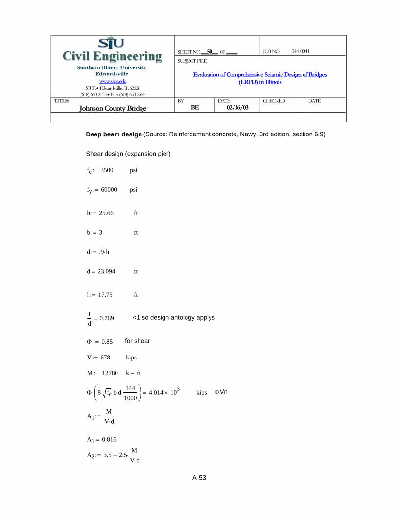
A2 3.5 2.5MV d⋅⋅−:=
A1 0.816=
A1MV d⋅
:=
ΦVnkipsΦ 8 fc⋅ b⋅ d⋅1441000⋅⎛⎜
⎝⎞⎠
⋅ 4.014 103×=
k ft−M 12780:=
kipsV 678:=
for shearΦ 0.85:=
<1 so design antology applys ld
0.769=
ftl 17.75:=
ftd 23.094=
d .9 h⋅:=
ftb 3:=
fth 25.66:=
psify 60000:=
psifc 3500:=
Shear design (expansion pier)
Deep beam design (Source: Reinforcement concrete, Nawy, 3rd edition, section 6.9)
SHEET NO __50__ 0F ____
JOB NO 044-0041
www.siue.edu
SIUE.• Edwardsville, IL 62026 (618) 650-2533 • Fax: (618) 650-2555
SUBJECT FILE
Evaluation of Comprehensive Seismic Design of Bridges (LRFD) in Illinois
TITLE:
Johnson County Bridge BY
BE DATE
02/16/03 CHECKED
DATE
A-53

SHEET NO __51__ 0F ____
JOB NO 044-0041
www.siue.edu
SIUE.• Edwardsville, IL 62026 (618) 650-2533 • Fax: (618) 650-2555
SUBJECT FILE
Evaluation of Comprehensive Seismic Design of Bridges (LRFD) in Illinois
TITLE:
Johnson County Bridge BY
BE DATE
02/16/03 CHECKED
DATE
A2 1.459= A2 < 3.5 OK
ρ .0062:=
Vc A2 1.9 fc⋅ 2500 ρ⋅V d⋅M
⋅+⎛⎜⎝
⎞⎠
⋅ b⋅ d⋅1441000⋅:=
Vc 1.913 103×= kips
Vcmax 6 fc⋅ b⋅ d⋅1441000⋅:=
Vcmax 3.541 103×= > Vc so use Vc
Vc 1.913 103×= kips
VsVΦ
Φ Vc⋅−:=
Vs 828.574−= Shear reinforcement is not required
A-54

< 80 in2 OKin2Asmin 33.255=
Asmin max 3fc
fy⋅ b⋅ d⋅ 144⋅ 200 b⋅
d 144⋅
fy⋅,
⎛⎜⎝
⎞
⎠:=
> 50.56 in2, so we use 80#9 (1% steel, As=80.01 in2)in2As 80=
AsM 12000⋅
Φ b⋅ fy⋅ j⋅ d⋅:=
ftj d⋅ 10.65=
j 0.461=
j.6 l( )
d:=
< 1 so jd=0.6llh
0.692=
ftl 17.75=
k ft−M 1.278 104×=
Φ 1:=
Flexure design for deep beam
SHEET NO __52__ 0F ____
JOB NO 044-0041
www.siue.edu
SIUE.• Edwardsville, IL 62026 (618) 650-2533 • Fax: (618) 650-2555
SUBJECT FILE
Evaluation of Comprehensive Seismic Design of Bridges (LRFD) in Illinois
TITLE:
Johnson County Bridge BY
BE DATE
02/16/03 CHECKED
DATE
A-55

Controls (3.6')in1.5 0.08 M⋅12V
⋅ 4400 εy⋅ db⋅+⎛⎜⎝
⎞⎠
43.531=
kV 1276:=
k ft−M 21504:=
for #11indb 1.41:=
εy 0.00207:=
4-
in18
3-
in16
H⋅ 33.5=
inH 201:=
2-
inD 33=
Controls but last check should be done after design inD h 3−:=
1-
thickness of the wallinh 36:=
Plastic hinge zone length (this length will modify after the reinforcement design)MCEER Guide Spec. 4.9.1
For the fixed bent
SHEET NO __53__ 0F ____
JOB NO 044-0041
www.siue.edu
SIUE.• Edwardsville, IL 62026 (618) 650-2533 • Fax: (618) 650-2555
SUBJECT FILE
Evaluation of Comprehensive Seismic Design of Bridges (LRFD) in Illinois
TITLE:
Johnson County Bridge BY
BE DATE
02/16/03 CHECKED
DATE
A-56

Axial earthquake force
MtopL 0:= k ft−
MbotL M:=
OS 1.5:= Over strength factor
Mp_topL OS MtopL⋅:=
Mp_topL 0= k ft−
Mp_botL OS MbotL⋅:=
Mp_botL 3.226 104×= k ft−
VuLMp_topL Mp_botL+( ) 12⋅
L R⋅:=
VuL 2.407 103×= kips
Vu_analysisVR
:= kips
Vu max VuL Vu_analysis,( ):=
Vu 2.407 103×= kips
SHEET NO __54__ 0F ____
JOB NO 044-0041
www.siue.edu
SIUE.• Edwardsville, IL 62026 (618) 650-2533 • Fax: (618) 650-2555
SUBJECT FILE
Evaluation of Comprehensive Seismic Design of Bridges (LRFD) in Illinois
TITLE:
Johnson County Bridge BY
BE DATE
02/16/03 CHECKED
DATE
Wall pier transverse reinforcementMethod 2: Explicit Approach(Guide Spec 8.8.2.3)Fixed pier308"X36" (2.53% steel, 84#11 at top and 6#11 each side)
N 180:= number of longitudinal reinforcement
R 0.8:= R-factor for joint (table 3.1-2)
L 201:= in Height of the pier
Ab 1.56:= in2 Area of rebars for longitudinal rebar
For longitudinal case which is govern for this bridge. For transverse direction, value of 2 is used for the case of fixed - fixed.Λ 1:= fixed - free
Pd 534:= kips Axial dead load in the pier
Pe 59:= kips
A-57

VpΛ
2Pe⋅
Dp
L⋅:=
Vp 4.55= kips Contribution due to arch action
φ 0.85:= For shear
Vu 2.407 103×= kips
VsVu
φVp Vc+( )−:=
Vs 2.467 103×= kips
Kshape .5:= For wall in weak axis (MCEER 8.8.2.3)
fyh 60:= ksi For the transverse and longitudinal steel
fsu 1.5 fyh⋅:= Ultimate tensile stress of the longitudinal reinforcement
fsu 90= ksi
SHEET NO __55__ 0F ____
JOB NO 044-0041
www.siue.edu
SIUE.• Edwardsville, IL 62026 (618) 650-2533 • Fax: (618) 650-2555
SUBJECT FILE
Evaluation of Comprehensive Seismic Design of Bridges (LRFD) in Illinois
TITLE:
Johnson County Bridge BY
BE DATE
02/16/03 CHECKED
DATE
fc 3500:= psi
bw 308:= in
d D:= in
h 36:= in
Vc .6 fc( )⎡⎣ ⎤⎦ bw⋅d
1000⋅:= Shear resistance in the end regions (plastic hinge zone)
Vc 360.786= kips
L 201= in
Dp 36 5−:= Width of the column core
Dp 31= in
Dp
L0.154=
A-58

ρv 4.68 10 3−×=
For fixed - fixed case of transverse directionρv Kshape 2⋅ Λρt
φ⋅
fsufyh⋅
Ag
Av⋅
Dp
L⋅ tanθ⋅:=
Method 1: Implicit Shear Detailing Approach(Guide Spec. 8.8.2.3)
< Ash OKin2Avs
legs0.192=
Avs sVs
fyh Dpp⋅⋅ tanθ⋅:=
Width of the perimeter transverse directionDpp h 4−:=
tanθ 0.636=
tanθ 1.6 ρv_pr⋅Av
Λ ρt⋅ Ag⋅⋅
⎛⎜⎝
⎞
⎠
.25
:=
in2Ag 1.109 104×=
Ag bw h⋅:=
ρv_pr 2.76 10 3−×=
ρv_pr legsAsh
bw s⋅⋅:=
Number of legslegs 17:=
Area of transverse reinforcement (ties) #4Ash .2:=
< 4" OK (MCEER 8.8.2.4) for plastic hinge zoneins 4:=
Longitudinal reinforcement ratioρt .0248:=
in2Av 1.016 104×=
Shear area Av bw d⋅:=
SHEET NO __56__ 0F ____
JOB NO 044-0041
www.siue.edu
SIUE.• Edwardsville, IL 62026 (618) 650-2533 • Fax: (618) 650-2555
SUBJECT FILE
Evaluation of Comprehensive Seismic Design of Bridges (LRFD) in Illinois
TITLE:
Johnson County Bridge BY
BE DATE
02/16/03 CHECKED
DATE
A-59

Avs smVs
fyh Dpp⋅⋅ tanθ⋅:=
inDpp 32=
tanθ 0.547=
tanθ 1.6 ρv_pr⋅Av
Λ ρt⋅ Ag⋅⋅
⎛⎜⎝
⎞
⎠
.25
:=
Ag 1.109 104×=
ρv_pr 1.515 10 3−×=
ρv_pr legs_outplasticAshm
bw sm⋅⋅:=
#4Ashm .2:=
Maximum spacing (MCEER 8.8.2.6)insm 6:=
kipsVs 1.625 103×=
VsVu
φVp Vc+( )−:=
Vp 4.55=
kipsVc 1.203 103×=
Shear resistance of concrete out side of the plastic hinge zoneVc 2 fc⋅ bw⋅d
1000⋅:=
legs_outplastic 14:=
Outside the plastic hinge zoneMethod 2: Explicit Approach8.8.2.3
< Ash provided OKin2Avs
legs_new0.192=
legs_new 30:=
Avs ρv bw⋅ s⋅:=
SHEET NO __57__ 0F ____
JOB NO 044-0041
www.siue.edu
SIUE.• Edwardsville, IL 62026 (618) 650-2533 • Fax: (618) 650-2555
SUBJECT FILE
Evaluation of Comprehensive Seismic Design of Bridges (LRFD) in Illinois
TITLE:
Johnson County Bridge BY
BE DATE
02/16/03 CHECKED
DATE
A-60

Ag 1.109 104×=
ρt 0.025=
ρs1 0.027=
ρs1 legsAsh
Dpp s⋅⋅:=
< 4" OK (MCEER 8.8.2.4)ins 4:=
in2Ac 9.06 103×=
Ac bw 6−( ) h 6−( )⋅:=
in2Ash 0.2=
Strain energy capacityksiUsf 15.95:=
ksifyh 60=
legs 17=
Transverse reinforcement for confinement at plastic hinges (Pmax column) (Guide Spec. 8.8.2.4)
Use method 2ρpr 2.814 10 3−×=
ρpr legs_newAshm
bw sm⋅⋅:=
ρvstar 2.708 10 3−×=
ρvstar ρv2 fc⋅
fyh 1000⋅−:=
fyh 60=
legs_new 26:=
Method 1: Implicit Shear Detailing Approach
< Ash OKin2Avs
legs_outplastic0.198=
SHEET NO __58__ 0F ____
JOB NO 044-0041
www.siue.edu
SIUE.• Edwardsville, IL 62026 (618) 650-2533 • Fax: (618) 650-2555
SUBJECT FILE
Evaluation of Comprehensive Seismic Design of Bridges (LRFD) in Illinois
TITLE:
Johnson County Bridge BY
BE DATE
02/16/03 CHECKED
DATE
A-61

For the uplift effectkipsPeminL Pd .8⋅:=
kipsPd 534=
Explicit Shear Detailing Approach (Pmin Column)(Guide Spec. 8.8.2.3) In longitudinal direction
ins 4=
ρs 0.027=
ρs max ρs1 ρs2,( ):=
OKinsmax 18.024=
smax legs_pmaxAsh
Dpp ρs2⋅⋅:=
legs_pmax Ash⋅
s Dp⋅0.027=
Include the area of total legs in both direction of cross section (Guide Spec. 8.8.2.4)
legs_pmax 17:=
legs 17=
Dp 31=
OKρs2 5.895 10 3−×=
ρs2 0.008fc
1000Usf⋅ 15
1000Pe
fc Ag⋅ρt
1000 fyh⋅
fc⋅+
⎛⎜⎝
⎞
⎠
2
⋅Ag
Ac
⎛⎜⎝
⎞
⎠
2
⋅ 1−⎡⎢⎢⎣
⎤⎥⎥⎦
⋅:=
Factored axial load include seismic effectkipsPe 593=
Pe Pd Pe+:=
fc 3.5 103×=
SHEET NO __59__ 0F ____
JOB NO 044-0041
www.siue.edu
SIUE.• Edwardsville, IL 62026 (618) 650-2533 • Fax: (618) 650-2555
SUBJECT FILE
Evaluation of Comprehensive Seismic Design of Bridges (LRFD) in Illinois
TITLE:
Johnson County Bridge BY
BE DATE
02/16/03 CHECKED
DATE
A-62

ρv legsAsh
bw s⋅⋅:=
in2Ash 0.2=
ins 4:=
Vs 2.442 103×=
VsVu
φVc− Vp−:=
kipsVp 28.825=
Vp Λ PeL⋅Dp
L 2⋅⋅:=
kipsVc 360.786=
Vc 0.6 fc⋅Av
1000⋅:=
Av 1.016 104×=
kipsVu 2.407 103×=
VuMp_bot 12⋅
L R⋅:=
Mp_bot OS MbotL⋅:=
kipsPeL 373.8=
PeL Pd OS PeminL Pd−( )⋅+:=
OS 1.5=
k ft−MbotL 2.15 104×=
k ft−Mp_top 0:=
kipsPeminL 427.2=
SHEET NO __60__ 0F ____
JOB NO 044-0041
www.siue.edu
SIUE.• Edwardsville, IL 62026 (618) 650-2533 • Fax: (618) 650-2555
SUBJECT FILE
Evaluation of Comprehensive Seismic Design of Bridges (LRFD) in Illinois
TITLE:
Johnson County Bridge BY
BE DATE
02/16/03 CHECKED
DATE
A-63
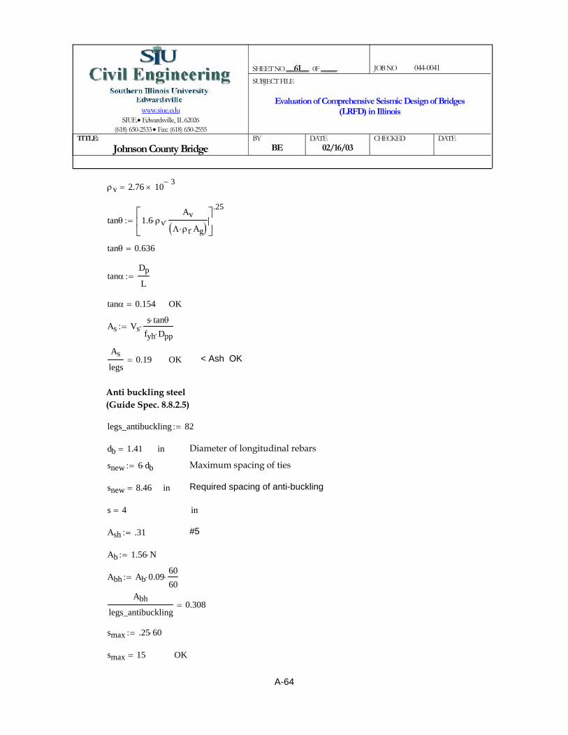
OKsmax 15=
smax .25 60⋅:=
Abh
legs_antibuckling0.308=
Abh Ab 0.09⋅6060⋅:=
Ab 1.56 N⋅:=
#5Ash .31:=
ins 4=
Required spacing of anti-bucklinginsnew 8.46=
Maximum spacing of tiessnew 6 db⋅:=
Diameter of longitudinal rebarsindb 1.41=
legs_antibuckling 82:=
Anti buckling steel(Guide Spec. 8.8.2.5)
< Ash OKOKAs
legs0.19=
As Vss tanθ⋅
fyh Dpp⋅⋅:=
OKtanα 0.154=
tanαDp
L:=
tanθ 0.636=
tanθ 1.6 ρv⋅Av
Λ ρt⋅ Ag⋅( )⋅
⎡⎢⎣
⎤⎥⎦
.25
:=
ρv 2.76 10 3−×=
SHEET NO __61__ 0F ____
JOB NO 044-0041
www.siue.edu
SIUE.• Edwardsville, IL 62026 (618) 650-2533 • Fax: (618) 650-2555
SUBJECT FILE
Evaluation of Comprehensive Seismic Design of Bridges (LRFD) in Illinois
TITLE:
Johnson County Bridge BY
BE DATE
02/16/03 CHECKED
DATE
A-64

#5Ash 0.31=
in2Ash_rq 27.36=
Ash_rq ρhmin bw 4−( )⋅ h⋅:=
ρhmin .0025:=
MCEER Guide Spec. 8.8.3
Shear design in transverse direction
Summery of transverse reinforcement for central column#5@4" with 82 legs in 6' of top, #4@6" with 14 legs in the rest of the wall
1.512
4400 εy⋅ db⋅ .0812Mp_botL
Vu⋅+
⎛⎜⎝
⎞
⎠⋅ 3.213=
controlsftMp_botL
Vu1 .85
Mp_botL
1.5⎛⎜⎝
⎞⎠
Mp_botL⋅−
⎡⎢⎢⎣
⎤⎥⎥⎦
⋅ 5.807=
kipsVuL 2.407 103×=
k ft−Mp_botL 3.226 104×=
Vu 2.407 103×=
ftLp 5.043=
Lph 4−( )12
1tanθ
.5 tanθ⋅+⎛⎜⎝
⎞⎠
⋅:=
tanθ 0.636=
Final check for the plastic hinge zone(Guide Spec. 4.9.1)
SHEET NO __62__ 0F ____
JOB NO 044-0041
www.siue.edu
SIUE.• Edwardsville, IL 62026 (618) 650-2533 • Fax: (618) 650-2555
SUBJECT FILE
Evaluation of Comprehensive Seismic Design of Bridges (LRFD) in Illinois
TITLE:
Johnson County Bridge BY
BE DATE
02/16/03 CHECKED
DATE
A-65

kips (So minimum horizontal reinforcement is adequate for this pier)Vrq 1379:=
kipsV 1.817 103×=
V min Vn Vr,( ):=
kipsVn 1.817 103×=
Vn φ .756 fc⋅ ρhmin fyh⋅ 1000⋅+( )⋅ bw 3−( )⋅h
1000⋅:=
kipsVr 1.949 103×=
Vr3
1000fc bw 3−( ) h⋅:=
insh 4:=
Number of horizontal reinforcementN_h 88.258=
N_hAsh_rq
Ash:=
SHEET NO __63__ 0F ____
JOB NO 044-0041
www.siue.edu
SIUE.• Edwardsville, IL 62026 (618) 650-2533 • Fax: (618) 650-2555
SUBJECT FILE
Evaluation of Comprehensive Seismic Design of Bridges (LRFD) in Illinois
TITLE:
Johnson County Bridge BY
BE DATE
02/16/03 CHECKED
DATE
A-66

Controls (2.7')in1.5 0.08 M⋅12V
⋅ 4400 εy⋅ db⋅+⎛⎜⎝
⎞⎠
29.869=
kV 271:=
k ft−M 3050:=
for #8indb 1:=
εy 0.00207:=
4-
in18
3-
in16
H⋅ 35.5=
inH 213:=
2-
inD 23=
controls but last check should be done after design inD h 3−:=
1-
thickness of the wallinh 26:=
Plastic hinge zone length (this length will modify after the reinforcement design)MCEER Guide Spec. 4.91
For the expansion bent
SHEET NO __64__ 0F ____
JOB NO 044-0041
www.siue.edu
SIUE.• Edwardsville, IL 62026 (618) 650-2533 • Fax: (618) 650-2555
SUBJECT FILE
Evaluation of Comprehensive Seismic Design of Bridges (LRFD) in Illinois
TITLE:
Johnson County Bridge BY
BE DATE
02/16/03 CHECKED
DATE
A-67

Axial earthquake force
MtopL 0:= k ft−
MbotL M:=
OS 1.5:= Over strength factor
Mp_topL OS MtopL⋅:=
Mp_topL 0= k ft−
Mp_botL OS MbotL⋅:=
Mp_botL 4.575 103×= k ft−
VuLMp_topL Mp_botL+( ) 12⋅
L R⋅:=
VuL 322.183= kips
Vu_analysisVR
:= kips
Vu max VuL Vu_analysis,( ):=
Vu 338.75= kips
SHEET NO __65__ 0F ____
JOB NO 044-0041
www.siue.edu
SIUE.• Edwardsville, IL 62026 (618) 650-2533 • Fax: (618) 650-2555
SUBJECT FILE
Evaluation of Comprehensive Seismic Design of Bridges (LRFD) in Illinois
TITLE:
Johnson County Bridge BY
BE DATE
02/16/03 CHECKED
DATE
Wall pier transverse reinforcementMethod 2: Explicit Approach (Guide Spec 8.8.2.3)Fixed pier308"X26" (1.01% steel, 38#9 at top and 2#9 each side)
N 80:= number of longitudinal reinforcement
R 0.8:= R-factor for joint (table 3.1-2)
L 213:= in Height of the pier
Ab 1:= in2 Area of rebars for longitudinal rebar
For longitudinal case which is govern for this bridge. For transverse direction, value of 2 is used for the case of fixed - fixed.Λ 1:= fixed - free
Pd 487:= kips Axial dead load in the pier
Pe 60:= kips
A-68
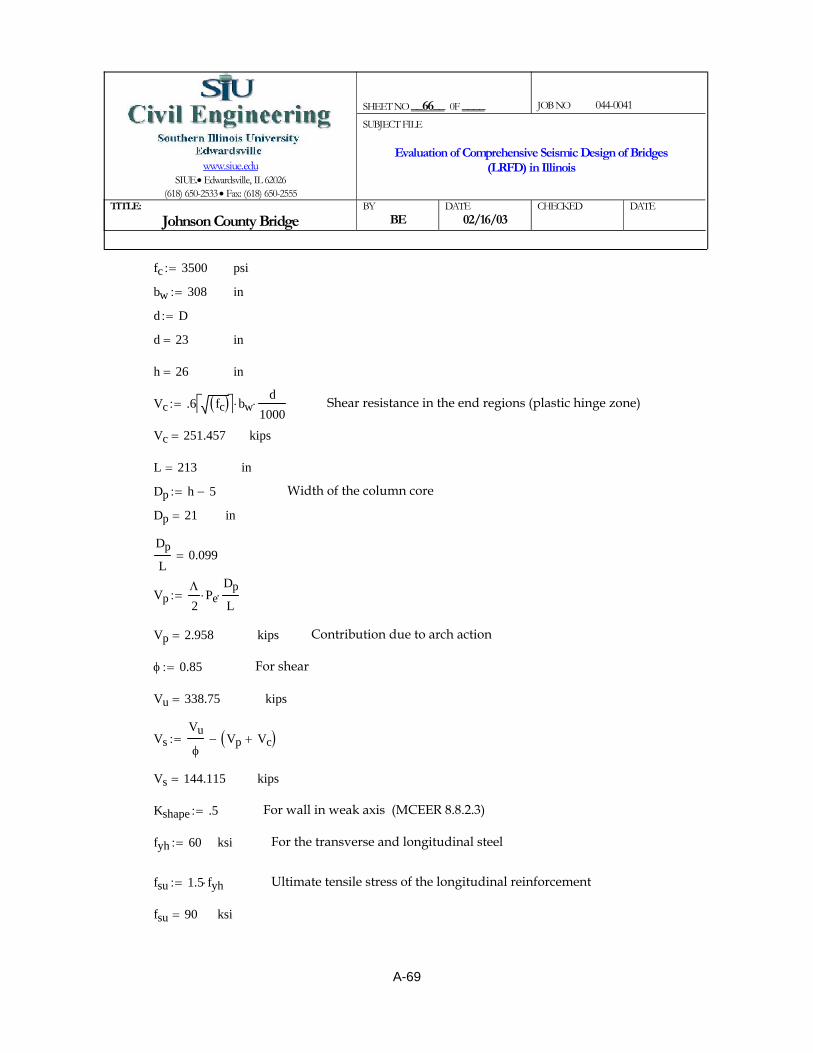
VpΛ
2Pe⋅
Dp
L⋅:=
Vp 2.958= kips Contribution due to arch action
φ 0.85:= For shear
Vu 338.75= kips
VsVu
φVp Vc+( )−:=
Vs 144.115= kips
Kshape .5:= For wall in weak axis (MCEER 8.8.2.3)
fyh 60:= ksi For the transverse and longitudinal steel
fsu 1.5 fyh⋅:= Ultimate tensile stress of the longitudinal reinforcement
fsu 90= ksi
SHEET NO __66__ 0F ____
JOB NO 044-0041
www.siue.edu
SIUE.• Edwardsville, IL 62026 (618) 650-2533 • Fax: (618) 650-2555
SUBJECT FILE
Evaluation of Comprehensive Seismic Design of Bridges (LRFD) in Illinois
TITLE:
Johnson County Bridge BY
BE DATE
02/16/03 CHECKED
DATE
fc 3500:= psi
bw 308:= in
d D:=
d 23= in
h 26= in
Vc .6 fc( )⎡⎣ ⎤⎦ bw⋅d
1000⋅:= Shear resistance in the end regions (plastic hinge zone)
Vc 251.457= kips
L 213= in
Dp h 5−:= Width of the column core
Dp 21= in
Dp
L0.099=
A-69

ρv 8.744 10 4−×=
For fixed - fixed case of transverse directionρv Kshape 2⋅ Λρt
φ⋅
fsufyh⋅
Ag
Av⋅
Dp
L⋅ tanθ⋅:=
Method 1: Implicit Shear Detailing Approach(Guide Spec. 8.8.2.3)
< Ash OKin2Avs
legs0.064=
Avs sVs
fyh Dpp⋅⋅ tanθ⋅:=
Width of the perimeter transverse directionDpp h 4−:=
tanθ 0.44=
tanθ 1.6 ρv_pr⋅Av
Λ ρt⋅ Ag⋅⋅
⎛⎜⎝
⎞
⎠
.25
:=
in2Ag 8.008 103×=
Ag bw h⋅:=
ρv_pr 2.679 10 4−×=
ρv_pr legsAsh
bw s⋅⋅:=
Number of legslegs 3:=
Area of transverse reinforcement (ties) #3Ash .11:=
< 4" OK (MCEER 8.8.2.4) for plastic hinge zoneins 4:=
Longitudinal reinforcement ratioρt .0101:=
in2Av 7.084 103×=
Shear area Av bw d⋅:=
SHEET NO __67__ 0F ____
JOB NO 044-0041
www.siue.edu
SIUE.• Edwardsville, IL 62026 (618) 650-2533 • Fax: (618) 650-2555
SUBJECT FILE
Evaluation of Comprehensive Seismic Design of Bridges (LRFD) in Illinois
TITLE:
Johnson County Bridge BY
BE DATE
02/16/03 CHECKED
DATE
A-70

Avs smVs
fyh Dpp⋅⋅ tanθ⋅:=
inDpp 22=
tanθ 0.359=
tanθ 1.6 ρv_pr⋅Av
Λ ρt⋅ Ag⋅⋅
⎛⎜⎝
⎞
⎠
.25
:=
Ag 8.008 103×=
ρv_pr 1.19 10 4−×=
ρv_pr legs_outplasticAshm
bw sm⋅⋅:=
#3Ashm .11:=
Maximum spacing (MCEER 8.8.2.6)insm 6:=
kipsVs 442.619−=
VsVu
φVp Vc+( )−:=
Vp 2.958=
kipsVc 838.19=
Shear resistance of concrete out side of the plastic hinge zoneVc 2 fc⋅ bw⋅d
1000⋅:=
legs_outplastic 2:=
Outside the plastic hinge zoneMethod 2: Explicit Approach8.8.2.3
< Ash provided OKin2Avs
legs_new0.108=
legs_new 10:=
Avs ρv bw⋅ s⋅:=
SHEET NO __68__ 0F ____
JOB NO 044-0041
www.siue.edu
SIUE.• Edwardsville, IL 62026 (618) 650-2533 • Fax: (618) 650-2555
SUBJECT FILE
Evaluation of Comprehensive Seismic Design of Bridges (LRFD) in Illinois
TITLE:
Johnson County Bridge BY
BE DATE
02/16/03 CHECKED
DATE
A-71

Ag 8.008 103×=
ρt 0.01=
ρs1 3.75 10 3−×=
ρs1 legsAsh
Dpp s⋅⋅:=
< 4" OK (MCEER 8.8.2.4)ins 4:=
in2Ac 6.04 103×=
Ac bw 6−( ) h 6−( )⋅:=
in2Ash 0.11=
Strain energy capacityksiUsf 15.95:=
ksifyh 60=
legs 3=
Transverse reinforcement for confinement at plastic hinges (Pmax column) (Guide Spec. 8.8.2.4)
ρpr 1.19 10 4−×=
ρpr legs_newAshm
bw sm⋅⋅:=
No reinforcement is requiredρvstar 1.098− 10 3−×=
ρvstar ρv2 fc⋅
fyh 1000⋅−:=
fyh 60=
legs_new 2:=
Method 1: Implicit Shear Detailing Approach
No reinforcement is requiredin2Avs
legs_outplastic0.362−=
SHEET NO __69__ 0F ____
JOB NO 044-0041
www.siue.edu
SIUE.• Edwardsville, IL 62026 (618) 650-2533 • Fax: (618) 650-2555
SUBJECT FILE
Evaluation of Comprehensive Seismic Design of Bridges (LRFD) in Illinois
TITLE:
Johnson County Bridge BY
BE DATE
02/16/03 CHECKED
DATE
A-72

kipsPeminL Pd .8⋅:=
kipsPd 487=
Explicit Shear Detailing Approach (Pmin Column)(Guide Spec. 8.8.2.3) In longitudinal direction
ins 4=
ρs 3.75 10 3−×=
ρs max ρs1 ρs2,( ):=
OKinsmax 2.272− 103×=
smax legs_pmaxAsh
Dpp ρs2⋅⋅:=
Include the area of total legs in both direction of cross section (Guide Slegs_pmax Ash⋅
s Dp⋅0.022=
legs_pmax 17:=
legs 3=
Dp 21=
No reinforcement is requiredρs2 3.741− 10 5−×=
ρs2 0.008fc
1000Usf⋅ 15
1000Pe
fc Ag⋅ρt
1000 fyh⋅
fc⋅+
⎛⎜⎝
⎞
⎠
2
⋅Ag
Ac
⎛⎜⎝
⎞
⎠
2
⋅ 1−⎡⎢⎢⎣
⎤⎥⎥⎦
⋅:=
Factored axial load include seismic effectkipsPe 547=
Pe Pd Pe+:=
fc 3.5 103×=
SHEET NO __70__ 0F ____
JOB NO 044-0041
www.siue.edu
SIUE.• Edwardsville, IL 62026 (618) 650-2533 • Fax: (618) 650-2555
SUBJECT FILE
Evaluation of Comprehensive Seismic Design of Bridges (LRFD) in Illinois
TITLE:
Johnson County Bridge BY
BE DATE
02/16/03 CHECKED
DATE
A-73

ρv legsAsh
bw s⋅⋅:=
in2Ash 0.11=
ins 4:=
Vs 110.777=
VsVu
φVc− Vp−:=
kipsVp 16.805=
Vp Λ PeL⋅Dp
L 2⋅⋅:=
kipsVc 251.457=
Vc 0.6 fc⋅Av
1000⋅:=
Av 7.084 103×=
kipsVu 322.183=
VuMp_bot 12⋅
L R⋅:=
Mp_bot OS MbotL⋅:=
kipsPeL 340.9=
PeL Pd OS PeminL Pd−( )⋅+:=
OS 1.5=
k ft−MbotL 3.05 103×=
k ft−Mp_top 0:=
kipsPeminL 389.6=
SHEET NO __71__ 0F ____
JOB NO 044-0041
www.siue.edu
SIUE.• Edwardsville, IL 62026 (618) 650-2533 • Fax: (618) 650-2555
SUBJECT FILE
Evaluation of Comprehensive Seismic Design of Bridges (LRFD) in Illinois
TITLE:
Johnson County Bridge BY
BE DATE
02/16/03 CHECKED
DATE
A-74

OKsmax 15=
smax .25 60⋅:=
Abh
legs_antibuckling0.196=
Abh Ab 0.09⋅6060⋅:=
Ab 0.79 N⋅:=
#4Ash .2:=
ins 4=
Required spacing for antibuckling reinforcementinsnew 6.768=
Maximum spacing of tiessnew 6 db⋅:=
Diameter of longitudinal rebarsindb 1.128:=
legs_antibuckling 29:=
Anti buckling steel(Guide Spec. 8.8.2.5)
< Ash OKOKAs
legs0.049=
As Vss tanθ⋅
fyh Dpp⋅⋅:=
OKtanα 0.099=
tanαDp
L:=
tanθ 0.44=
tanθ 1.6 ρv⋅Av
Λ ρt⋅ Ag⋅( )⋅
⎡⎢⎣
⎤⎥⎦
.25
:=
ρv 2.679 10 4−×=
SHEET NO __72__ 0F ____
JOB NO 044-0041
www.siue.edu
SIUE.• Edwardsville, IL 62026 (618) 650-2533 • Fax: (618) 650-2555
SUBJECT FILE
Evaluation of Comprehensive Seismic Design of Bridges (LRFD) in Illinois
TITLE:
Johnson County Bridge BY
BE DATE
02/16/03 CHECKED
DATE
A-75

Ash 0.2=
in2Ash_rq 19.76=
Ash_rq ρhmin bw 4−( )⋅ h⋅:=
ρhmin .0025:=
MCEER Guide Spec. 8.8.3
Shear design in transverse direction
Summery of transverse reinforcement for central column#4@4" with 29 legs in 6.2' of bottom of the wall
1.512
4400 εy⋅ db⋅ .0812Mp_botL
Vu⋅+
⎛⎜⎝
⎞
⎠⋅ 2.988=
controlsftMp_botL
Vu1 .85
Mp_botL
1.5⎛⎜⎝
⎞⎠
Mp_botL⋅−
⎡⎢⎢⎣
⎤⎥⎥⎦
⋅ 6.153=
kipsVuL 322.183=
k ft−Mp_botL 4.575 103×=
ftLp 4.569=
Lph 4−( )12
1tanθ
.5 tanθ⋅+⎛⎜⎝
⎞⎠
⋅:=
tanθ 0.44=
Final check for the plastic hinge zone(Guide Spec. 4.9.1)
SHEET NO __73__ 0F ____
JOB NO 044-0041
www.siue.edu
SIUE.• Edwardsville, IL 62026 (618) 650-2533 • Fax: (618) 650-2555
SUBJECT FILE
Evaluation of Comprehensive Seismic Design of Bridges (LRFD) in Illinois
TITLE:
Johnson County Bridge BY
BE DATE
02/16/03 CHECKED
DATE
A-76

kips (So minimum horizontal reinforcement is adequate for this pier)Vrq 811:=
kipsV 1.308 103×=
V min Vn Vr,( ):=
kipsVn 1.308 103×=
Vn φ .756 fc⋅ ρhmin fyh⋅ 1000⋅+( )⋅ bw 4−( )⋅h
1000⋅:=
kipsVr 1.403 103×=
Vr3
1000fc bw 4−( ) h⋅:=
insh 4:=
Number of horizontal reinforcementN_h 98.8=
N_hAsh_rq
Ash:=
SHEET NO __74__ 0F ____
JOB NO 044-0041
www.siue.edu
SIUE.• Edwardsville, IL 62026 (618) 650-2533 • Fax: (618) 650-2555
SUBJECT FILE
Evaluation of Comprehensive Seismic Design of Bridges (LRFD) in Illinois
TITLE:
Johnson County Bridge BY
BE DATE
02/16/03 CHECKED
DATE
A-77

For the longitudinal steel
L 201:= in Height of the pier
Ab 1.56:= in2 Area of rebars for longitudinal rebar
Pd 534:= kips Axial dead load in the pier
Pe 59:= kips Axial earthquake force
MbotL 21504:= k ft−
OS 1.5:= Over strength factor
Mp_botL OS MbotL⋅:=
Mp_botL 3.226 104×= k ft−
SHEET NO __75__ 0F ____
JOB NO 044-0041
www.siue.edu
SIUE.• Edwardsville, IL 62026 (618) 650-2533 • Fax: (618) 650-2555
SUBJECT FILE
Evaluation of Comprehensive Seismic Design of Bridges (LRFD) in Illinois
TITLE:
Johnson County Bridge BY
BE DATE
02/16/03 CHECKED
DATE
Fixed BentWall pier connection designMethod 1: Implicit Shear Detailing Approach (Guide spec. 8.8.4.1, 8.8.2.3, 8.8.2.4)Fixed pier308"X36" (2.53% steel, 84#11 at top and 6#11 each side)
N 180:= number of longitudinal reinforcement
bw 36:= in Height of pile cap
Hc 36:= in Height of the joint
h 36:= in Dimension of the column
D h 3−:= in
D 33= in
R 0.8:= R-factor for joint (table 3.1-2)
εy .00207:=
A-78

ksi
Av bw d⋅:= Shear area
Av 1.016 104×= in2
ρt .0253:= Longitudinal reinforcement ratio
s 4:= in < 4" OK (MCEER 8.8.2.4) for plastic hinge zone
Ash .2:= #4 Area of transverse reinforcement (ties)
legs 16:= Number of legs
ρv_pr legsAsh
bw s⋅⋅:=
ρv_pr 2.597 10 3−×=
Ag bw h⋅:=
Ag 1.109 104×= in2
SHEET NO __76__ 0F ____
JOB NO 044-0041
www.siue.edu
SIUE.• Edwardsville, IL 62026 (618) 650-2533 • Fax: (618) 650-2555
SUBJECT FILE
Evaluation of Comprehensive Seismic Design of Bridges (LRFD) in Illinois
TITLE:
Johnson County Bridge BY
BE DATE
02/16/03 CHECKED
DATE
fc 3500:= psi
bw 308:= in
d D:= in
L 201= in
Dp 36 4−:= Width of the column core
Dp 32= in
φ 0.85:= For shear
fyh 60:= ksi For the transverse and longitudinal steel
fsu 1.5 fyh⋅:= Ultimate tensile stress of the longitudinal reinforcement
fsu 90=
A-79

in2Asc 280.8=
Longitudinal reinforcement in columnAsc N Ab⋅:=
Core dimension of tied column in the direction under constructionDpp 31:=
fsu 1.5 fyh⋅:=
ksifyh 60:=
Ag D2:=
Shear area Av=bw*dAv Dp2
:=
For shearφ 0.85:=
Width of the column core inDp 32=
For longitudinal rebarin2Ab 1.56:=
Length of the columninL 201=
SHEET NO __77__ 0F ____
JOB NO 044-0041
www.siue.edu
SIUE.• Edwardsville, IL 62026 (618) 650-2533 • Fax: (618) 650-2555
SUBJECT FILE
Evaluation of Comprehensive Seismic Design of Bridges (LRFD) in Illinois
TITLE:
Johnson County Bridge BY
BE DATE
02/16/03 CHECKED
DATE
A-80

Amid 2.07 104×= in2
fvPe
Amid:= Average axial stress in the vertical direction
fv 2.85 10 3−×= ksi
hb Hc:= Joint depth
hb 36= in
hc D:= Dimension of column
hc 33= in
bje 2hc:= effective joint width for shear stress calculations
bje 66= in
SHEET NO __78__ 0F ____
JOB NO 044-0041
www.siue.edu
SIUE.• Edwardsville, IL 62026 (618) 650-2533 • Fax: (618) 650-2555
SUBJECT FILE
Evaluation of Comprehensive Seismic Design of Bridges (LRFD) in Illinois
TITLE:
Johnson County Bridge BY
BE DATE
02/16/03 CHECKED
DATE
Explicit approach for joint design (Guide Spec. 8.8.4.2, C8.8.4.2, 8.8.4.2.2, 8.8.4.3.1, 8.8.4.3.2, 8.8.4.3.3)
Bottom of the wall in longitudinal direction
fh 0:= Average axial stress in the horizontal direction
P Pd Pe+:=
P 593= kips Maximum axial force include earthquake effect
Mp_botL 3.226 104×= k ft− From push over analysis
bb 25 12⋅:= in Width of pile cap
Lmid_dept_jt D Hc+:=
Lmid_dept_jt 69= in
Amid bb Lmid_dept_jt⋅:=
A-81

38#7 in 36" of the jointAclamp
.637.44=
Aclamp 22.464=
Vertical reinforcement (Clamping reinforcement) (Guide Spec. 8.8.4.3.2)Aclamp .08 Asc⋅:=
75#7 vertical legs in (development length) each sideAjv
.674.88=
Use #7
in2Ajv 44.928=
Vertical reinforcement (Stirrups) (Guide Spec. 8.8.4.3.2)Ajv .16Asc:=
OKpc_max 0.875=
Maximum compression stresspc_max.25
1000fc⋅:=
pc 4.938=
Principal compression stresspcfh fv+( )
2
fh fv−( )2
⎡⎢⎣
⎤⎥⎦
2
vhv2
++:=
Not OK, we should provide some horizontal reinforcementpt_max 0.207=
Maximum tension stresspt_max3.5
1000fc⋅:=
pt 4.935−=
Principal tension stressptfh fv+( )
2
fh fv−( )2
⎡⎢⎣
⎤⎥⎦
2
vhv2
+−:=
ksivhv 4.937=
Joint shear stressvhvMp_botL 12⋅
hb hc⋅ bje⋅:=
SHEET NO __79__ 0F ____
JOB NO 044-0041
www.siue.edu
SIUE.• Edwardsville, IL 62026 (618) 650-2533 • Fax: (618) 650-2555
SUBJECT FILE
Evaluation of Comprehensive Seismic Design of Bridges (LRFD) in Illinois
TITLE:
Johnson County Bridge BY
BE DATE
02/16/03 CHECKED
DATE
A-82

Use #4@6" with 41 legssmax 9.211=
smax legsAsh
Dpp ρs⋅⋅:=
legs 41:=
ins 4=
in2Ash .2:=
OKρs_min 3.451 10 3−×=
Minimum required horizontal reinforcement (Guide Spec. 8.8.4.2.2)ρs_min3.5
1000
fcfyh⋅:=
ρs 0.029=
Hoops (Guide Spec. 8.8.4.3.4)ρs .4Asc
ld112
:=
.4 1.41⋅ fyh⋅ 33.84=
inld11 62.539=
ld11 1.25 1.56⋅fyh
fc1000
⋅:=
23#9 in 40" length each sideAh 22.464=
Horizontal reinforcement (Guide Spec. 8.8.4.3.3)Ah 0.08 Asc⋅:=
inld9 22.791=
in0.3 1.128⋅ fyh⋅ 20.304=
Development length for #9 (AASHTO LRFD 5.11.2.2.1-1)ld9 .63 1.128⋅fyh
fc1000
⋅:=
SHEET NO __80__ 0F ____
JOB NO 044-0041
www.siue.edu
SIUE.• Edwardsville, IL 62026 (618) 650-2533 • Fax: (618) 650-2555
SUBJECT FILE
Evaluation of Comprehensive Seismic Design of Bridges (LRFD) in Illinois
TITLE:
Johnson County Bridge BY
BE DATE
02/16/03 CHECKED
DATE
A-83

L 213:= in Height of the pier
Ab 1:= in2 Area of rebars for longitudinal rebar
For longitudinal case which is govern for this bridge. For transverse direction, value of 2 is used for the case of fixed - fixed.Λ 1:= fixed - free
Pd 486:= kips Axial dead load in the pier
Pe 60:= kips Axial earthquake force
MbotL 3050:= k ft−
OS 1.5:= Over strength factor
Mp_botL OS MbotL⋅:=
Mp_botL 4.575 103×= k ft−
SHEET NO __81__ 0F ____
JOB NO 044-0041
www.siue.edu
SIUE.• Edwardsville, IL 62026 (618) 650-2533 • Fax: (618) 650-2555
SUBJECT FILE
Evaluation of Comprehensive Seismic Design of Bridges (LRFD) in Illinois
TITLE:
Johnson County Bridge BY
BE DATE
02/16/03 CHECKED
DATE
Expansion BentWall pier connection designMethod 1: Implicit Shear Detailing Approach (Guide spec. 8.8.4.1, 8.8.2.3, 8.8.2.4)
308"X26" (1.01% steel, 38#9 at top and 2#9 each side)
N 80:= number of longitudinal reinforcement
bw 36:= in Height of pile cap
Hc 36:= in Height of the joint
h 26:= in Dimension of the column
D h 3−:= in
D 23= in
R 0.8:= R-factor for joint (table 3.1-2)
εy .00207:= For the longitudinal steel
A-84

ksi
Av bw d⋅:= Shear area
Av 7.084 103×= in2
ρt .0101:= Longitudinal reinforcement ratio
s 4:= in < 4" OK (MCEER 8.8.2.4) for plastic hinge zone
Ash .2:= #4 Area of transverse reinforcement (ties)
legs 16:= Number of legs
ρv_pr legsAsh
bw s⋅⋅:=
ρv_pr 2.597 10 3−×=
Ag bw h⋅:=
Ag 8.008 103×= in2
SHEET NO __82__ 0F ____
JOB NO 044-0041
www.siue.edu
SIUE.• Edwardsville, IL 62026 (618) 650-2533 • Fax: (618) 650-2555
SUBJECT FILE
Evaluation of Comprehensive Seismic Design of Bridges (LRFD) in Illinois
TITLE:
Johnson County Bridge BY
BE DATE
02/16/03 CHECKED
DATE
fc 3500:= psi
bw 308:= in
d D:= in
L 213= in
Dp h 4−:= Width of the column core
Dp 22= in
φ 0.85:= For shear
fyh 60:= ksi For the transverse and longitudinal steel
fsu 1.5 fyh⋅:= Ultimate tensile stress of the longitudinal reinforcement
fsu 90=
A-85

in2Asc 80=
Longitudinal reinforcement in columnAsc N Ab⋅:=
Core dimension of tied column in the direction under constructionDpp h 5−:=
fsu 1.5 fyh⋅:=
ksifyh 60:=
Ag D2:=
Shear area Av=bw*dAv Dp2
:=
For shearφ 0.85:=
Width of the column core inDp 22=
For longitudinal rebarin2Ab 1=
Length of the columninL 213=
SHEET NO __83__ 0F ____
JOB NO 044-0041
www.siue.edu
SIUE.• Edwardsville, IL 62026 (618) 650-2533 • Fax: (618) 650-2555
SUBJECT FILE
Evaluation of Comprehensive Seismic Design of Bridges (LRFD) in Illinois
TITLE:
Johnson County Bridge BY
BE DATE
02/16/03 CHECKED
DATE
A-86

Amid 1.77 104×= in2
fvPe
Amid:= Average axial stress in the vertical direction
fv 3.39 10 3−×= ksi
hb Hc:= Joint depth
hb 36= in
hc D:= Dimension of column
hc 23= in
bje 2hc:= effective joint width for shear stress calculations
bje 46= in
SHEET NO __84__ 0F ____
JOB NO 044-0041
www.siue.edu
SIUE.• Edwardsville, IL 62026 (618) 650-2533 • Fax: (618) 650-2555
SUBJECT FILE
Evaluation of Comprehensive Seismic Design of Bridges (LRFD) in Illinois
TITLE:
Johnson County Bridge BY
BE DATE
02/16/03 CHECKED
DATE
Explicit approach for joint design (Guide Spec. 8.8.4.2, C8.8.4.2, 8.8.4.2.2, 8.8.4.3.1, 8.8.4.3.2, 8.8.4.3.3)
Bottom of the column in longitudinal direction
fh 0:= Average axial stress in the horizontal direction
P Pd Pe+:=
P 546= kips Maximum axial force include earthquake effect
Mp_botL 4.575 103×= k ft− From push over analysis
bb 25 12⋅:= in Width of pile cap
Lmid_dept_jt D Hc+:=
Lmid_dept_jt 59= in
Amid bb Lmid_dept_jt⋅:=
A-87

11#7 in 36" of the jointAclamp
.610.667=
Aclamp 6.4=
Vertical reinforcement (Clamping reinforcement) (Guide Spec. 8.8.4.3.2)Aclamp .08 Asc⋅:=
22#7 vertical legs in (development length) each sideAjv
.621.333=
Use #7
in2Ajv 12.8=
Vertical reinforcement (Stirrups) (Guide Spec. 8.8.4.3.2)Ajv .16Asc:=
OKpc_max 0.875=
Maximum compression stresspc_max.25
1000fc⋅:=
pc 1.443=
Principal compression stresspcfh fv+( )
2
fh fv−( )2
⎡⎢⎣
⎤⎥⎦
2
vhv2
++:=
Not OK, we should provide some horizontal reinforcementpt_max 0.207=
Maximum tension stresspt_max3.5
1000fc⋅:=
pt 1.44−=
Principal tension stressptfh fv+( )
2
fh fv−( )2
⎡⎢⎣
⎤⎥⎦
2
vhv2
+−:=
ksivhv 1.441=
Joint shear stressvhvMp_botL 12⋅
hb hc⋅ bje⋅:=
SHEET NO __85__ 0F ____
JOB NO 044-0041
www.siue.edu
SIUE.• Edwardsville, IL 62026 (618) 650-2533 • Fax: (618) 650-2555
SUBJECT FILE
Evaluation of Comprehensive Seismic Design of Bridges (LRFD) in Illinois
TITLE:
Johnson County Bridge BY
BE DATE
02/16/03 CHECKED
DATE
A-88
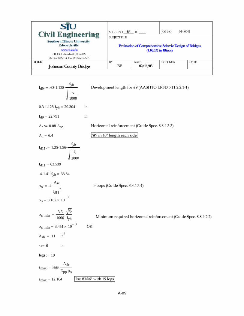
Use #3@6" with 19 legssmax 12.164=
smax legsAsh
Dpp ρs⋅⋅:=
legs 19:=
ins 6:=
in2Ash .11:=
OKρs_min 3.451 10 3−×=
Minimum required horizontal reinforcement (Guide Spec. 8.8.4.2.2)ρs_min3.5
1000
fcfyh⋅:=
ρs 8.182 10 3−×=
Hoops (Guide Spec. 8.8.4.3.4)ρs .4Asc
ld112
:=
.4 1.41⋅ fyh⋅ 33.84=
inld11 62.539=
ld11 1.25 1.56⋅fyh
fc1000
⋅:=
7#9 in 40" length each sideAh 6.4=
Horizontal reinforcement (Guide Spec. 8.8.4.3.3)Ah 0.08 Asc⋅:=
inld9 22.791=
in0.3 1.128⋅ fyh⋅ 20.304=
Development length for #9 (AASHTO LRFD 5.11.2.2.1-1)ld9 .63 1.128⋅fyh
fc1000
⋅:=
SHEET NO __86__ 0F ____
JOB NO 044-0041
www.siue.edu
SIUE.• Edwardsville, IL 62026 (618) 650-2533 • Fax: (618) 650-2555
SUBJECT FILE
Evaluation of Comprehensive Seismic Design of Bridges (LRFD) in Illinois
TITLE:
Johnson County Bridge BY
BE DATE
02/16/03 CHECKED
DATE
A-89

ft < ∆limit OK
Expansion Pier
W 400:= kips Average axial force at column
V 678:= kips
H20112
:=
H 16.75= ft
CVW
:=
C 1.695=
∆ limit .25 C⋅ H⋅:=
∆ limit 7.098= ft
∆ .28:= ft < ∆limit OK
SHEET NO __87__ 0F ____
JOB NO 044-0041
www.siue.edu
SIUE.• Edwardsville, IL 62026 (618) 650-2533 • Fax: (618) 650-2555
SUBJECT FILE
Evaluation of Comprehensive Seismic Design of Bridges (LRFD) in Illinois
TITLE:
Johnson County Bridge BY
BE DATE
02/16/03 CHECKED
DATE
P-∆ RequirementsGuide Spec. 8.3.4
Fix Pier
W 400:= kips Average axial force at column
V 1283:= kips
H20112
:=
H 16.75= ft
CVW
:=
C 3.208=
∆ limit .25 C⋅ H⋅:=
∆ limit 13.431= ft
∆ .28:=
A-90
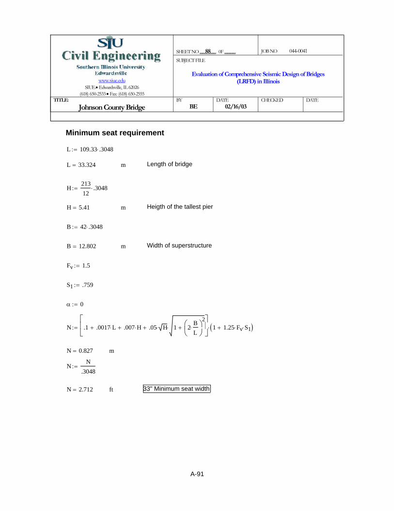
33" Minimum seat widthftN 2.712=
NN
.3048:=
mN 0.827=
N .1 .0017 L⋅+ .007 H⋅+ .05 H⋅ 1 2BL⋅⎛⎜
⎝⎞⎠
2+⋅+
⎡⎢⎣
⎤⎥⎦
1 1.25 Fv⋅ S1⋅+( )⋅:=
α 0:=
S1 .759:=
Fv 1.5:=
Width of superstructuremB 12.802=
B 42 .3048⋅:=
Heigth of the tallest piermH 5.41=
H21312
.3048⋅:=
Length of bridgemL 33.324=
L 109.33 .3048⋅:=
Minimum seat requirement
SHEET NO __88__ 0F ____
JOB NO 044-0041
www.siue.edu
SIUE.• Edwardsville, IL 62026 (618) 650-2533 • Fax: (618) 650-2555
SUBJECT FILE
Evaluation of Comprehensive Seismic Design of Bridges (LRFD) in Illinois
TITLE:
Johnson County Bridge BY
BE DATE
02/16/03 CHECKED
DATE
A-91

ft2Σd1 1.215 103×=
Σd1 6 13.52⋅ 6 4.52
⋅+:=
Σd1s2
12n1⋅ n12 1−( )⋅ m1⋅:=
Sum of the squares of the distances to each pile from the center or gravity of piles
n1 4:=Number of piles in the rowsNumber of rowsm1 3:=
s 9:=
Thickness of pile cap (ft)T 3:=
Length of wall (ft)L 25.67:=
Width of Wall (ft)W 2.17:=
Dimensions of Fixed pier
Axial (kips) M (kip-ft) Trans (case1) M (kip-ft) Long (case2)Fixed Long. 1014 8602 21504Pier Trans. 988 21835 8734Exp. Long. 764 1220 3050Pier Trans. 728 12780 5112
Moments and Forces acting on piles:
psiFy 60000:=
psiFc 4000:=
Pile cap design procedure for Johnson County bridge
SHEET NO __89__ 0F ____
JOB NO 044-0041
www.siue.edu
SIUE.• Edwardsville, IL 62026 (618) 650-2533 • Fax: (618) 650-2555
SUBJECT FILE
Evaluation of Comprehensive Seismic Design of Bridges (LRFD) in Illinois
TITLE:
Johnson County Bridge BY
NA DATE
03/11/03 CHECKED
DATE
A-92

y10 9−:=
x3 4.5−:= x7 4.5−:= x11 4.5−:=y3 9:= y7 0:= y11 9−:=
x4 13.5−:= x8 13.5−:= x12 13.5−:=
y4 9:= y8 0:= y12 9−:=
A 81:= ft2 Area for each pile
kip
ft3Soil unit weight
δ 0.12:=
ft soil highth 2:=
p A δ⋅ h⋅:=
p 19.44= kips Soil pressure for each pile
n 12:= Number of piles in the group
SHEET NO __90__ 0F ____
JOB NO 044-0041
www.siue.edu
SIUE.• Edwardsville, IL 62026 (618) 650-2533 • Fax: (618) 650-2555
SUBJECT FILE
Evaluation of Comprehensive Seismic Design of Bridges (LRFD) in Illinois
TITLE:
Johnson County Bridge BY
NA DATE
03/11/03 CHECKED
DATE
n2 3:= Number of rowsm2 4:= Number of piles in the rows
Σd2s2
12n2⋅ n22 1−( )⋅ m2⋅:= Σd2 8 92
⋅:=
Σd2 648= Or ft2
M1 21504:= kip ft−
kip ft−M2 8734:=
kipV 1014:=
Piles Coordinates:
x1 13.5:= x5 9:= x9 13.5:=
y1 9:= y5 0:= y9 9−:=
x2 4.5:= x6 4.5:= x10 4.5:=
y2 9:= y6 0:=
A-93

P8Vn
M1x8Σd1⋅+ M2
y8Σd2⋅+ p+:=
kipsP7 24.296=
P7Vn
M1x7Σd1⋅+ M2
y7Σd2⋅+ p+:=
kipsP6 183.584=
P6Vn
M1x6Σd1⋅+ M2
y6Σd2⋅+ p+:=
kipsP5 263.229=
P5Vn
M1x5Σd1⋅+ M2
y5Σd2⋅+ p+:=
kipsP4 13.688−=
P4Vn
M1x4Σd1⋅+ M2
y4Σd2⋅+ p+:=
kipsP3 145.601=
P3Vn
M1x3Σd1⋅+ M2
y3Σd2⋅+ p+:=
kipsP2 304.89=
P2Vn
M1x2Σd1⋅+ M2
y2Σd2⋅+ p+:=
kipsP1 464.179=
P1Vn
M1x1Σd1⋅+ M2
y1Σd2⋅+ p+:=
SHEET NO __91__ 0F ____
JOB NO 044-0041
www.siue.edu
SIUE.• Edwardsville, IL 62026 (618) 650-2533 • Fax: (618) 650-2555
SUBJECT FILE
Evaluation of Comprehensive Seismic Design of Bridges (LRFD) in Illinois
TITLE:
Johnson County Bridge BY
NA DATE
03/11/03 CHECKED
DATE
A-94

OKVuφ
Vc<Vuφ
546.093=
φ 0.85:=
kipsVc 1.81 103×=
Vc 4 Fc⋅ b⋅d
1000⋅:=
inb 69π:=
ind 33:=KipsVu 464.179=
Vu P1:=
Pile punching shear check:
kipsP12 256.299−=
P12Vn
M1x12Σd1⋅+ M2
y12Σd2⋅+ p+:=
kipsP11 97.01−=
P11Vn
M1x11Σd1⋅+ M2
y11Σd2⋅+ p+:=
kipsP10 62.279=
P10Vn
M1x10Σd1⋅+ M2
y10Σd2⋅+ p+:=
kipsP9 221.568=
P9Vn
M1x9Σd1⋅+ M2
y9Σd2⋅+ p+:=
kipsP8 134.993−=
SHEET NO __92__ 0F ____
JOB NO 044-0041
www.siue.edu
SIUE.• Edwardsville, IL 62026 (618) 650-2533 • Fax: (618) 650-2555
SUBJECT FILE
Evaluation of Comprehensive Seismic Design of Bridges (LRFD) in Illinois
TITLE:
Johnson County Bridge BY
NA DATE
03/11/03 CHECKED
DATE
A-95
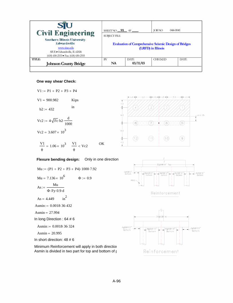
Minimum Reinforcement will apply in both directions.Asmin is divided in two part for top and bottom of pile cap
In short direction: 48 # 6
Asmin 20.995=
Asmin 0.0018 36⋅ 324⋅:=
In long Direction : 64 # 6
Asmin 27.994=
Asmin 0.0018 36⋅ 432⋅:=
in2As 4.449=
AsMu
Φ Fy⋅ 0.9⋅ d⋅:=
Φ 0.9:=Mu 7.136 106×=
Mu P1 P2+ P3+ P4+( ) 1000⋅ 7.92⋅:=
Only in one directionFlexure bending design:
V1φ
Vc2<V1φ
1.06 103×=
OK
Vc2 3.607 103×=
Vc2 4 Fc⋅ b2⋅d
1000⋅:=
b2 432:=in
KipsV1 900.982=
V1 P1 P2+ P3+ P4+:=
One way shear Check:
SHEET NO __93__ 0F ____
JOB NO 044-0041
www.siue.edu
SIUE.• Edwardsville, IL 62026 (618) 650-2533 • Fax: (618) 650-2555
SUBJECT FILE
Evaluation of Comprehensive Seismic Design of Bridges (LRFD) in Illinois
TITLE:
Johnson County Bridge BY
NA DATE
03/11/03 CHECKED
DATE
A-96

ft2Σd2 121.5=
Σd2s2
12n2⋅ n22 1−( )⋅ m2⋅:=
Σd2 6 4.52⋅:=
n2 2:=
m2 3:=ft2Σd1 324=
Σd1 4 92⋅:=Σd1
s2
12n1⋅ n12 1−( )⋅ m1⋅:=
n1 3:=
n 6:=m1 2:=
Axial (kips) M (kip-ft) Trans (case1) M (kip-ft) Long (case2)Fixed Long. 1014 8602 21504Pier Trans. 988 21835 8734Exp. Long. 764 1220 3050Pier Trans. 728 12780 5112
Pile cap Length (ft)l 27:=
Pile cap width (ft)w 18:=
Thickness of pile cap (ft)T 3:=
Length of wall (ft)L 25.67:=
Width of Wall (ft)W 2.17:=
Dimensions of Exp. pier
SHEET NO __94__ 0F ____
JOB NO 044-0041
www.siue.edu
SIUE.• Edwardsville, IL 62026 (618) 650-2533 • Fax: (618) 650-2555
SUBJECT FILE
Evaluation of Comprehensive Seismic Design of Bridges (LRFD) in Illinois
TITLE:
Johnson County Bridge BY
NA DATE
03/11/03 CHECKED
DATE
A-97

x3 9−:= x6 9−:=y3 4.5:= y6 4.5−:=
P1Vn
M1x1Σd1⋅+ M2
y1Σd2⋅+ p+:=
P1 546.959= kips
P2Vn
M1x2Σd1⋅+ M2
y2Σd2⋅+ p+:=
P2 191.959= kips
P3Vn
M1x3Σd1⋅+ M2
y3Σd2⋅+ p+:=
P3 163.041−= kips
P4Vn
M1x4Σd1⋅+ M2
y4Σd2⋅+ p+:=
P4 456.588= kips
P5Vn
M1x5Σd1⋅+ M2
y5Σd2⋅+ p+:=
SHEET NO __95__ 0F ____
JOB NO 044-0041
www.siue.edu
SIUE.• Edwardsville, IL 62026 (618) 650-2533 • Fax: (618) 650-2555
SUBJECT FILE
Evaluation of Comprehensive Seismic Design of Bridges (LRFD) in Illinois
TITLE:
Johnson County Bridge BY
NA DATE
03/11/03 CHECKED
DATE
M1 12780:= kip ft−
kip ft−M2 1220:=
kipV 764:=
Piles Coordinates:x1 9:= x4 9:=
y1 4.5:= y4 4.5−:=
x2 0:= x5 0:=
y2 4.5:= y5 4.5−:=
A-98

φ 0.85:=
Vuφ
643.481=Vuφ
Vc< OK
d 45:=
One way shear Check:
V1 P1 P2+ P3+( ) 0.74⋅:=
V1 426.148= Kips
inb2 324:=
Vc2 4 Fc⋅ b2⋅d
1000⋅:=
Vc2 3.688 103×=
OKV1φ
501.35=V1φ
Vc2<
SHEET NO __96__ 0F ____
JOB NO 044-0041
www.siue.edu
SIUE.• Edwardsville, IL 62026 (618) 650-2533 • Fax: (618) 650-2555
SUBJECT FILE
Evaluation of Comprehensive Seismic Design of Bridges (LRFD) in Illinois
TITLE:
Johnson County Bridge BY
NA DATE
03/11/03 CHECKED
DATE
P5 101.588= kips
P6Vn
M1x6Σd1⋅+ M2
y6Σd2⋅+ p+:=
P6 253.412−= kips
Pile punching shear check:
Vu P1:=
Vu 546.959= Kipsd 33:= in
b 69π:= in
Vc 4 Fc⋅ b⋅d
1000⋅:=
Vc 1.81 103×= kips
A-99
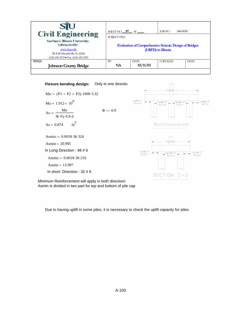
Due to having uplift in some piles, it is necessary to check the uplift capacity for piles.
Minimum Reinforcement will apply in both directions.Asmin is divided in two part for top and bottom of pile cap
In short Direction : 32 # 6
Asmin 13.997=
Asmin 0.0018 36⋅ 216⋅:=
In Long Direction : 48 # 6
Asmin 20.995=
Asmin 0.0018 36⋅ 324⋅:=
in2As 0.874=
AsMu
Φ Fy⋅ 0.9⋅ d⋅:=
Φ 0.9:=
Mu 1.912 106×=
Mu P1 P2+ P3+( ) 1000⋅ 3.32⋅:=
Only in one directionFlexure bending design:
SHEET NO __97__ 0F ____
JOB NO 044-0041
www.siue.edu
SIUE.• Edwardsville, IL 62026 (618) 650-2533 • Fax: (618) 650-2555
SUBJECT FILE
Evaluation of Comprehensive Seismic Design of Bridges (LRFD) in Illinois
TITLE:
Johnson County Bridge BY
NA DATE
03/11/03 CHECKED
DATE
A-100

f2 2.5 qu2⋅:= f2 65.881= psi less than .158qu2 109.722= psi
Qu1π Ds⋅ L1⋅ f1⋅ 144⋅
1000:= Qu1 311.788= kips
Qu2π Ds⋅ L2⋅ f2⋅ 144⋅
1000:= Qu2 2.146 103
×= kips
Wpile .150π
4Ds2⋅⎛⎜
⎝⎞⎠
⋅ L⋅:= Wpile 39.761= kips
Qallow 1.33Qu1 Qu2+ Wpile−( )
2⋅:=
kips
Qallow 1.608 103×=
Qallowuplift 1.330.7Qu1 0.7Qu2+ Wpile+( )
2⋅:=
Qallowuplift 1.17 103×= kips
SHEET NO __98__ 0F ____
JOB NO 044-0041
www.siue.edu
SIUE.• Edwardsville, IL 62026 (618) 650-2533 • Fax: (618) 650-2555
SUBJECT FILE
Evaluation of Comprehensive Seismic Design of Bridges (LRFD) in Illinois
TITLE:
Johnson County Bridge BY
NA DATE
03/11/03 CHECKED
DATE
Axial Capacity for uplift:
Ds 3:= ft
L1 4:= ft
L2 24:= ft
L 37.5:= ft
psiqu138 2000⋅
144:= qu1 527.778=
qu250 2000⋅
144:= psi qu2 694.444=
f1 2.5 qu1⋅:= f1 57.434= psi Less than .15 qu1⋅ 79.167= psi
A-101
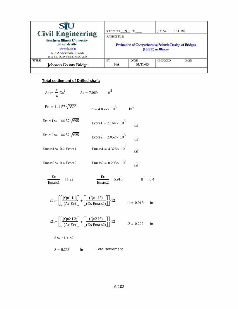
Total settlementinS 0.238=
S s1 s2+:=
ins2 0.222=s2
Qu2 L2⋅( )Ac Ec⋅( )
⎡⎢⎣
⎤⎥⎦
Qu2 If⋅( )Ds Emass2⋅( )
⎡⎢⎣
⎤⎥⎦
+⎡⎢⎣
⎤⎥⎦
12⋅:=
ins1 0.016=s1
Qu1 L1⋅( )Ac Ec⋅( )
⎡⎢⎣
⎤⎥⎦
Qu1 If⋅( )Ds Emass1⋅( )
⎡⎢⎣
⎤⎥⎦
+⎡⎢⎣
⎤⎥⎦
12⋅:=
If 0.4:=Ec
Emass25.916=
EcEmass1
11.22=
ksfEmass2 8.208 104×=Emass2 0.4 Ecore2⋅:=
SHEET NO __99__ 0F ____
JOB NO 044-0041
www.siue.edu
SIUE.• Edwardsville, IL 62026 (618) 650-2533 • Fax: (618) 650-2555
SUBJECT FILE
Evaluation of Comprehensive Seismic Design of Bridges (LRFD) in Illinois
TITLE:
Johnson County Bridge BY
NA DATE
03/11/03 CHECKED
DATE
Total settlement of Drilled shaft:
Acπ
4Ds2⋅:= Ac 7.069= ft2
Ec 144 57⋅ 3500⋅:= Ec 4.856 105×= ksf
Ecore1 144 57⋅ 695⋅:= Ecore1 2.164 105×= ksf
Ecore2 144 57⋅ 625⋅:= Ecore2 2.052 105×= ksf
Emass1 0.2 Ecore1⋅:= Emass1 4.328 104×= ksf
A-102

Civil Engineering www.siue.edu/civilSIUE, Edwardsville, IL 62025-1800(618)650-2533 Fax: (618)650-2555_______________________
TITLE:
Johnson County Bridge
SUBJECT FILE:
Evaluation of Comprehensive Seismic Design of Bridges
(LRFD) in Illinois___________________
AASHTOStandard Specifications
BY: _________ J.B.______
________________CHECKED: _____
W.N.M.W.N.M.________________DATE:__________
6/24/2004________________
Sheet No: 1 of 32
Appendix B -- Detailed Computations for Seismic Analysis and Design of the Johnson County Bridge Using AASHTO Specifications
B-1

Civil Engineering www.siue.edu/civilSIUE, Edwardsville, IL 62025-1800(618)650-2533 Fax: (618)650-2555_______________________
TITLE:
Johnson County Bridge
SUBJECT FILE:
Evaluation of Comprehensive Seismic Design of Bridges
(LRFD) in Illinois___________________
AASHTOStandard Specifications
BY: _________ J.B.______
________________CHECKED: _____
W.N.M.W.N.M.________________DATE:__________
6/24/2004________________
Sheet No: 2 of 32
Table of contents of Appendix- B Page
Overview of SAP 2000 Model………………………………………B-3
LPILE Graphs.............................................................................B-7
Spring Calculations…………..………………………………………B-9
SAP Model Output…………….………………………………………B-12
Pile Design……………………………………………………………B-15
Wall Pier Design……………...………………………………………B-20
Pile cap……………………………………………………………… B-29
Summary of Reinforcement……………………………………….. B-32
B-2
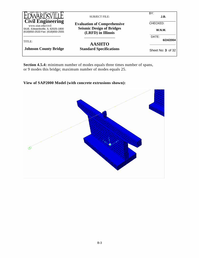
Civil Engineering www.siue.edu/civilSIUE, Edwardsville, IL 62025-1800(618)650-2533 Fax: (618)650-2555_______________________
TITLE:
Johnson County Bridge
SUBJECT FILE:
Evaluation of Comprehensive Seismic Design of Bridges
(LRFD) in Illinois___________________
AASHTOStandard Specifications
BY: _________ J.B.______
________________CHECKED: _____
W.N.M.W.N.M.________________DATE:__________
6/24/2004________________
Sheet No: 3 of 32
Section 4.5.4: minimum number of modes equals three times number of spans, or 9 modes this bridge; maximum number of modes equals 25. View of SAP2000 Model (with concrete extrusions shown):
B-3

Civil Engineering www.siue.edu/civilSIUE, Edwardsville, IL 62025-1800(618)650-2533 Fax: (618)650-2555_______________________
TITLE:
Johnson County Bridge
SUBJECT FILE:
Evaluation of Comprehensive Seismic Design of Bridges
(LRFD) in Illinois___________________
AASHTOStandard Specifications
BY: _________ J.B.______
________________CHECKED: _____
W.N.M.W.N.M.________________DATE:__________
6/24/2004________________
Sheet No: 4 of 32
Enlarged View of Translational and Rotational Springs:
B-4

Civil Engineering www.siue.edu/civilSIUE, Edwardsville, IL 62025-1800(618)650-2533 Fax: (618)650-2555_______________________
TITLE:
Johnson County Bridge
SUBJECT FILE:
Evaluation of Comprehensive Seismic Design of Bridges
(LRFD) in Illinois___________________
AASHTOStandard Specifications
BY: _________ J.B.______
________________CHECKED: _____
W.N.M.W.N.M.________________DATE:__________
6/24/2004________________
Sheet No: 5 of 32
Mode Shape 1 – Period = .6981 seconds
Mode Shape 2 – Period = .1915 seconds
B-5

Civil Engineering www.siue.edu/civilSIUE, Edwardsville, IL 62025-1800(618)650-2533 Fax: (618)650-2555_______________________
TITLE:
Johnson County Bridge
SUBJECT FILE:
Evaluation of Comprehensive Seismic Design of Bridges
(LRFD) in Illinois___________________
AASHTOStandard Specifications
BY: _________ J.B.______
________________CHECKED: _____
W.N.M.W.N.M.________________DATE:__________
6/24/2004________________
Sheet No: 6 of 32
Mode Shape 3 – Period = .1416 seconds
Mode Shape 5 – Period = .1073 seconds
B-6

Civil Engineering www.siue.edu/civilSIUE, Edwardsville, IL 62025-1800(618)650-2533 Fax: (618)650-2555_______________________
TITLE:
Johnson County Bridge
SUBJECT FILE:
Evaluation of Comprehensive Seismic Design of Bridges
(LRFD) in Illinois___________________
AASHTOStandard Specifications
BY: _________ J.B.______
________________CHECKED: _____
W.N.M.W.N.M.________________DATE:__________
6/24/2004________________
Sheet No: 7 of 32
Exp. Pier
Exp. Pier
B-7
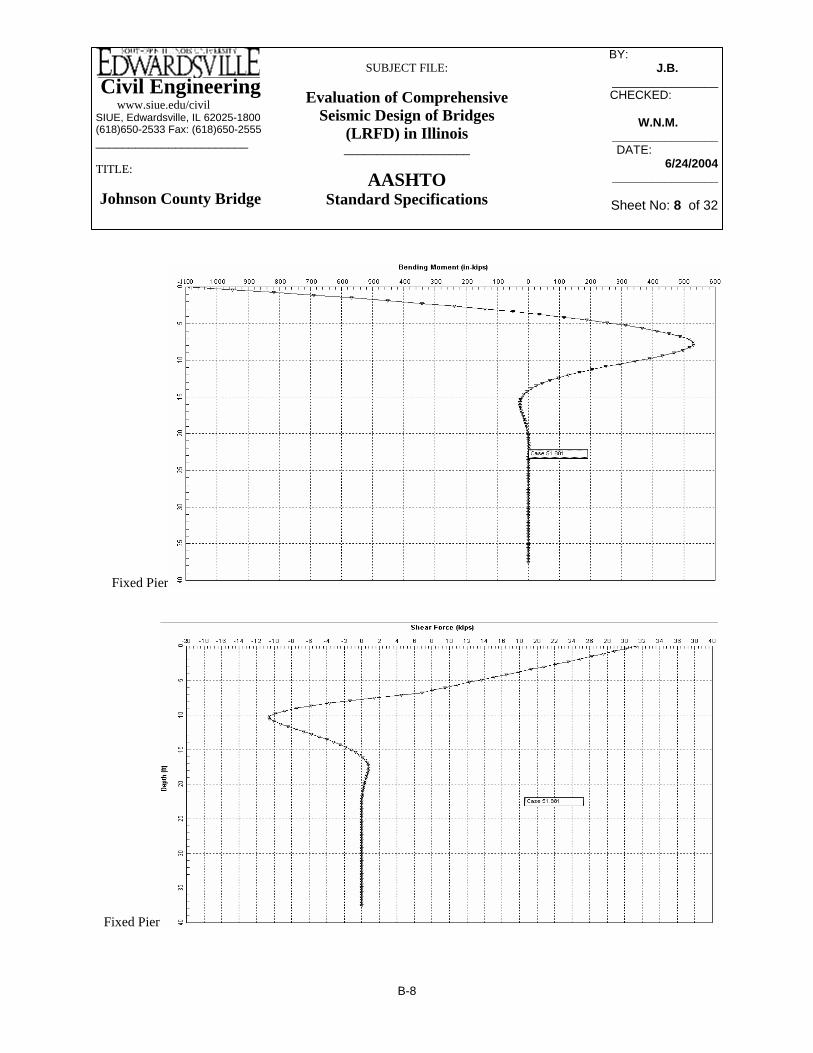
Civil Engineering www.siue.edu/civilSIUE, Edwardsville, IL 62025-1800(618)650-2533 Fax: (618)650-2555_______________________
TITLE:
Johnson County Bridge
SUBJECT FILE:
Evaluation of Comprehensive Seismic Design of Bridges
(LRFD) in Illinois___________________
AASHTOStandard Specifications
BY: _________ J.B.______
________________CHECKED: _____
W.N.M.W.N.M.________________DATE:__________
6/24/2004________________
Sheet No: 8 of 32
Fixed Pier
Fixed Pier
B-8

Civil Engineering www.siue.edu/civilSIUE, Edwardsville, IL 62025-1800(618)650-2533 Fax: (618)650-2555_______________________
TITLE:
Johnson County Bridge
SUBJECT FILE:
Evaluation of Comprehensive Seismic Design of Bridges
(LRFD) in Illinois___________________
AASHTOStandard Specifications
BY: _________ J.B.______
________________CHECKED: _____
W.N.M.W.N.M.________________DATE:__________
6/24/2004________________
Sheet No: 9 of 32
Ec 57 3500⋅( ) 144⋅:= Ec 485591.8= ksf
kaxial ApileEc
Lpile⋅:= kaxial 2.288 104×=
kft
Using LPile:
shear 31.5:= kips
∆ .205:= in
klateral12shear
∆:= klateral 1.844 103×=
kft
Lateral Springs:
K.x = K.y => Kx 8 klateral⋅:= Kx 1.475 104×=kft
Kaxial 8 kaxial⋅:= Kaxial 1.831 105×=kft
Piles Springs For Fixed Pier
Pile Informationfor L-Pile input:
φ 18:= in ∆ .205:= in
clearcover 3:= in (to spiral edge)
6 #8 bars for vertical reinforcement
Results from L-Pile: Mu115012
:= Mu 96= k ft−
Spring Stiffness: Lpile45012
:= Lpile 37.5= ft
D 18:= in
Apile
π
4⎛⎜⎝
⎞⎠
D2⋅
⎡⎢⎣
⎤⎥⎦
144:= Apile 1.767= ft2
B-9

Civil Engineering www.siue.edu/civilSIUE, Edwardsville, IL 62025-1800(618)650-2533 Fax: (618)650-2555_______________________
TITLE:
Johnson County Bridge
SUBJECT FILE:
Evaluation of Comprehensive Seismic Design of Bridges
(LRFD) in Illinois___________________
AASHTOStandard Specifications
BY: _________ J.B.______
________________CHECKED: _____
W.N.M.W.N.M.________________DATE:__________
6/24/2004________________
Sheet No: 10 of 32
Lpile45012
:= Lpile 37.5= ft
D 18:= in
Apile
π
4⎛⎜⎝
⎞⎠
D2⋅
⎡⎢⎣
⎤⎥⎦
144:= Apile 1.767= ft2
Ec 57 3500⋅( ) 144⋅:= Ec 485591.8= ksf
kaxial ApileEc
Lpile⋅:= kaxial 2.288 104×=
kft
Using LPile:
shear 17.75:= kips
∆ .05:= in
klateral12shear
∆:= klateral 4.26 103×=
kft
Rotational Springs:
Krx kaxial( ) 8 3.752( )⋅⎡⎣ ⎤⎦⋅:= Krx 2.574 106×=
Kry kaxial( ) 4 3.752( )⋅⎡⎣ ⎤⎦ 4 11.252( )⋅⎡⎣ ⎤⎦+⎡⎣ ⎤⎦⋅:= Kry 1.287 107×=
Krz klateral( ) 4 11.8592( )⋅ 2 5.3032( )+⎡⎣ ⎤⎦⋅:= Krz 1.141 106×=
Piles Springs For Expansion Pier
Pile Informationfor L-Pile input:
φ 18:= in ∆ .205:= in
clearcover 3:= in (to spiral edge)
6 #8 bars for vertical reinforcement
Results from L-Pile: Mu55012
:= Mu 46= k ft−
Spring Stiffness:
B-10

Civil Engineering www.siue.edu/civilSIUE, Edwardsville, IL 62025-1800(618)650-2533 Fax: (618)650-2555_______________________
TITLE:
Johnson County Bridge
SUBJECT FILE:
Evaluation of Comprehensive Seismic Design of Bridges
(LRFD) in Illinois___________________
AASHTOStandard Specifications
BY: _________ J.B.______
________________CHECKED: _____
W.N.M.W.N.M.________________DATE:__________
6/24/2004________________
Sheet No: 11 of 32
Krz 2.636 106×=Krz klateral( ) 4 11.8592( )⋅ 2 5.3032( )+⎡⎣ ⎤⎦⋅:=
Kry 1.287 107×=Kry kaxial( ) 4 3.752( )⋅⎡⎣ ⎤⎦ 4 11.252( )⋅⎡⎣ ⎤⎦+⎡⎣ ⎤⎦⋅:=
Krx 2.574 106×=Krx kaxial( ) 8 3.752( )⋅⎡⎣ ⎤⎦⋅:=
Rotational Springs:
kft
Kaxial 1.831 105×=Kaxial 8 kaxial⋅:=
kft
Kx 3.408 104×=Kx 8 klateral⋅:=K.x = K.y =>
Lateral Springs:
B-11

Civil Engineering www.siue.edu/civilSIUE, Edwardsville, IL 62025-1800(618)650-2533 Fax: (618)650-2555_______________________
TITLE:
Johnson County Bridge
SUBJECT FILE:
Evaluation of Comprehensive Seismic Design of Bridges
(LRFD) in Illinois___________________
AASHTOStandard Specifications
BY: _________ J.B.______
________________CHECKED: _____
W.N.M.W.N.M.________________DATE:__________
6/24/2004________________
Sheet No: 12 of 32
M O D A L P A R T I C I P A T I N G M A S S R A T I O S
With Springs for Division 1-A MODE PERIOD INDIVIDUAL MODE (%) UX UY UZ
1 0.6981 66.18 0.00 0.002 0.1915 13.23 0.00 0.003 0.1416 12.81 0.00 0.374 0.1304 0.48 0.00 10.355 0.1073 0.00 87.50 0.006 0.0741 0.00 0.00 15.847 0.0719 0.00 0.00 61.088 0.0714 7.24 0.00 0.009 0.0666 0.00 4.01 0.00
10 0.0559 0.00 0.00 0.0111 0.0530 0.00 0.27 0.0012 0.0439 0.00 0.00 9.7913 0.0326 0.00 0.00 0.0614 0.0306 0.01 0.00 0.0015 0.0263 0.00 0.01 0.0016 0.0229 0.00 0.00 0.0017 0.0217 0.05 0.00 0.0018 0.0207 0.00 0.00 0.7619 0.0183 0.00 0.00 0.0020 0.0166 0.00 4.06 0.0021 0.0162 0.00 0.00 0.9622 0.0118 0.00 0.00 0.0023 0.0117 0.00 0.00 0.0024 0.0115 0.00 0.00 0.0025 0.0108 0.00 0.00 0.00
100.00 95.85 99.22
B-12

Civil Engineering www.siue.edu/civilSIUE, Edwardsville, IL 62025-1800(618)650-2533 Fax: (618)650-2555_______________________
TITLE:
Johnson County Bridge
SUBJECT FILE:
Evaluation of Comprehensive Seismic Design of Bridges
(LRFD) in Illinois___________________
AASHTOStandard Specifications
BY: _________ J.B.______
________________CHECKED: _____
W.N.M.W.N.M.________________DATE:__________
6/24/2004________________
Sheet No: 13 of 32
Top 115 535 0 0Bottom 54 862 0 0
Top 15 890 0 0Bottom 56 288 0 0
Top 210 0 190 7Bottom 229 0 3619 8
Top 5 0 0 11Bottom 60 0 749 11
Top 57.5 268 0 0Bottom 27 431 0 0
Top 7.5 445 0 0Bottom 28 144 0 0
Top 105 0 95 4Bottom 115 0 1810 4
Top 3 0 0 6Bottom 30 0 375 6
DIVISION 1-A Forces & Moments - EQtrans
Transverse
Support / Location Shear 3 kips
Moment 2 kip-ft
Moment 3 kip-ft
Axial kips
Shear 2 kips
Moment 2 kip-ft
Moment 3 kip-ft
Fix Pier
Exp Pier
DIVISION 1-A Forces & Moments - EQlong
LongitudinalAxial kips
Support / Location
Fix Pier
Exp Pier
DIVISION 1-A Forces & Moments - Eqtrans / RTransverse
Axial kips
Fix Pier
Exp Pier
DIVISION 1-A Forces & Moments - Eqlong / RLongitudinal
Support / Location Shear 3 kips
Moment 2 kip-ft
Moment 3 kip-ft
Fix Pier
Exp Pier
Support / Location Axial kips
Shear 2 kips
Moment 2 kip-ft
Moment 3 kip-ft
306468308479
Fix Pier
Exp Pier
Dead Load
Location Axial kips
B-13

Civil Engineering www.siue.edu/civilSIUE, Edwardsville, IL 62025-1800(618)650-2533 Fax: (618)650-2555_______________________
TITLE:
Johnson County Bridge
SUBJECT FILE:
Evaluation of Comprehensive Seismic Design of Bridges
(LRFD) in Illinois___________________
AASHTOStandard Specifications
BY: _________ J.B.______
________________CHECKED: _____
W.N.M.W.N.M.________________DATE:__________
6/24/2004________________
Sheet No: 14 of 32
Top 32 58 29 268 307Bottom 34 27 543 431 469
Top 1 8 0 445 310Bottom 9 28 112 144 481
Top 105 17 95 80 306Bottom 115 8 1810 129 468
Top 3 2 0 134 308Bottom 30 8 375 43 479
DIVISION 1-A
Moment 3 kip-ft
Forces & Moments - Load Case 1(1.00*Eqtrans + 0.30*Eqlong) + 1*DL
DIVISION 1-AForces & Moments - Load Case 2(1.00*Eqlong + 0.30*Eqtrans) + 1*DL
Moment 2 kip-ft
Fix Pier
Exp Pier
Axial kips
Support / Location Shear 2 kips
Shear 3 kip
Moment 2 kip-ft
Axial kips
Fix Pier
Exp Pier
Support / Location Shear 2 kips
Shear 3 kip
Moment 3 kip-ft
1.16924 0.040261.10282 0.041020.18865 0.05776 0.1971.17857 0.033410.2202 0.03352
0.02909 0.03396 0.045
Bottom of Fixed Pier Pile Cap
Top of Expansion PierBottom of Expansion Pier Pile Cap
Bearing of Fixed Pier
Bearing of Expansion Pier
Top of Fixed Pier
Displacement Longitudinal Direction (in)
Transverse Direction (in)
Max (in)
B-14

Civil Engineering www.siue.edu/civilSIUE, Edwardsville, IL 62025-1800(618)650-2533 Fax: (618)650-2555_______________________
TITLE:
Johnson County Bridge
SUBJECT FILE:
Evaluation of Comprehensive Seismic Design of Bridges
(LRFD) in Illinois___________________
AASHTOStandard Specifications
BY: _________ J.B.______
________________CHECKED: _____
W.N.M.W.N.M.________________DATE:__________
6/24/2004________________
Sheet No: 15 of 32
Qsr1 0= kips
Qsr2 π Br⋅ L2⋅ qsr2⋅1441000⋅:= Qsr2 585= kips
Wpile .150π
4Br
2⋅
⎛⎜⎝
⎞⎠
⋅ 37.5⋅:= Wpile 9.9= kips
Note: 1.33 increase in allowable load; Factor of Safety = 2.5 (AASHTO 4.6.5.4)
Qallow 1.33Qsr2 Wpile−( )
2.5⋅:=
Qallow 306= kips (Allowable Downward Force)
Qallowup 1.33.7 Qsr2⋅ Wpile+( )
2.5⋅:=
Qallowup 223= kips (Allowable Uplift Force)
Note: Q.ult = Q.s + Q.t - W.self (Compression) and .7*Q.s + W (uplift); Q.allow = Q.ult / FS
Axial Capacity (Side Resistance) of Limestone and Shale:
Br 1.5:= ft L1 5:= ft (Shale)
L2 11.5:= ft (Hard Limestone w/ occasional shale seams)
Co1 3.82000144
⋅:= Co1 52.778= psi(tons / ft^2)(1 ft^2 / 144 in^2)(2000 lb / ton) = psi
Co2 502000144
⋅:= Co2 694.444= psi
From Figure 4.6.5.3.1A:
qsr1 0:= qsr2 75:= psi
Qsr1 π Br⋅ L1⋅ 0⋅1441000⋅:=
B-15

Civil Engineering www.siue.edu/civilSIUE, Edwardsville, IL 62025-1800(618)650-2533 Fax: (618)650-2555_______________________
TITLE:
Johnson County Bridge
SUBJECT FILE:
Evaluation of Comprehensive Seismic Design of Bridges
(LRFD) in Illinois___________________
AASHTOStandard Specifications
BY: _________ J.B.______
________________CHECKED: _____
W.N.M.W.N.M.________________DATE:__________
6/24/2004________________
Sheet No: 16 of 32
Under the ultmiate load of 236 kips (118 tons), we will easily be under .4": Thus the shaft does not experience excessive settlement.
Value of E(m) is approximate
in12 ρs⋅ 0.128=ftρs 0.01064=ρs QIρs
Br Em⋅
⎛⎜⎜⎝
⎞
⎠
DrA Ec⋅
⎛⎜⎜⎝
⎞
⎠+
⎡⎢⎢⎣
⎤⎥⎥⎦
⋅:=
ksfEc 485592=
Ec 57000 3500⋅1441000⋅:=
ftDr 37.5:=
ft2A 1.767=Aπ
41.52⋅:=
ksfEm 5.76 105×=
Em 4 106⋅1441000⋅:=
ftBr 1.5=
Iρs .55:=
kipsQ 240:=
Total Settlement of a Drilled Shaft (4.6.5.5.2):
B-16

Civil Engineering www.siue.edu/civilSIUE, Edwardsville, IL 62025-1800(618)650-2533 Fax: (618)650-2555_______________________
TITLE:
Johnson County Bridge
SUBJECT FILE:
Evaluation of Comprehensive Seismic Design of Bridges
(LRFD) in Illinois___________________
AASHTOStandard Specifications
BY: _________ J.B.______
________________CHECKED: _____
W.N.M.W.N.M.________________DATE:__________
6/24/2004________________
Sheet No: 17 of 32
(Sum of squares of the distances to each pile from the center of the pile group)
Piles Loads:
Fpile1Pw8
⎛⎜⎝
⎞
⎠Meql
d1Σd1⋅
⎛⎜⎝
⎞⎠
+ Meqtd3Σd2⋅
⎛⎜⎝
⎞⎠
+:= Fpile1 236= kips
Fpile4Pw8
⎛⎜⎝
⎞
⎠Meql
d1Σd1⋅
⎛⎜⎝
⎞⎠
+ Meqtd3Σd2⋅
⎛⎜⎝
⎞⎠
−:= Fpile4 226= kips
Fpile5Pw8
⎛⎜⎝
⎞
⎠Meql
d1Σd1⋅
⎛⎜⎝
⎞⎠
− Meqtd3Σd2⋅
⎛⎜⎝
⎞⎠
+:= Fpile5 48−= kips
Fpile8Pw8
⎛⎜⎝
⎞
⎠Meql
d1Σd1⋅
⎛⎜⎝
⎞⎠
− Meqtd3Σd2⋅
⎛⎜⎝
⎞⎠
−:= Fpile8 58−= kips
Fpiledeadload .150π
41.52⋅
⎛⎜⎝
⎞⎠
⋅ 37.5⋅:= Fpiledeadload 10= kips
Note: Q.ult = Q.s + Q.t - W.self (Compression) and .7*Q.s + W (uplift); Q.allow = Q.ult / FS
Axial Force On A Pile (Fixed Pier):
Pw 712:= kips
Meql 4260:= k ft− Meqt 251:= k ft−
d1 3.75:= d2 3.75:= d3 11.25:=
(distant from center of pile group to center of closest pile center)
Σd1 8 d12( )⋅:= Σd1 112.5= ft2 (weak axis)
Σd2 4 d22( )⋅ 4 d32( )⋅+:= Σd2 562.5= ft2 (strong axis)
B-17

Civil Engineering www.siue.edu/civilSIUE, Edwardsville, IL 62025-1800(618)650-2533 Fax: (618)650-2555_______________________
TITLE:
Johnson County Bridge
SUBJECT FILE:
Evaluation of Comprehensive Seismic Design of Bridges
(LRFD) in Illinois___________________
AASHTOStandard Specifications
BY: _________ J.B.______
________________CHECKED: _____
W.N.M.W.N.M.________________DATE:__________
6/24/2004________________
Sheet No: 18 of 32
kipsFpile8 45=Fpile8Pw8
⎛⎜⎝
⎞
⎠Meql
d1Σd1⋅
⎛⎜⎝
⎞⎠
− Meqtd3Σd2⋅
⎛⎜⎝
⎞⎠
−:=
kipsFpile5 47=Fpile5Pw8
⎛⎜⎝
⎞
⎠Meql
d1Σd1⋅
⎛⎜⎝
⎞⎠
− Meqtd3Σd2⋅
⎛⎜⎝
⎞⎠
+:=
kipsFpile4 108=Fpile4Pw8
⎛⎜⎝
⎞
⎠Meql
d1Σd1⋅
⎛⎜⎝
⎞⎠
+ Meqtd3Σd2⋅
⎛⎜⎝
⎞⎠
−:=
kipsFpile1 110=Fpile1Pw8
⎛⎜⎝
⎞
⎠Meql
d1Σd1⋅
⎛⎜⎝
⎞⎠
+ Meqtd3Σd2⋅
⎛⎜⎝
⎞⎠
+:=
Piles Loads:
(Sum of squares of the distances to each pile from the center of the pile group)
(strong axis) ft2
Axial Force On A Pile (Expansion Pier):
Pw 619:= kips
Meql 942:= k ft− Meqt 41:= k ft−
d1 3.75:= d2 3.75:= d3 11.25:=
(distant from center of pile group to center of closest pile center)
Σd1 8 d12( )⋅:= Σd1 112.5= ft2 (weak axis)
Σd2 4 d22( )⋅ 4 d32( )⋅+:= Σd2 562.5=
B-18

Civil Engineering www.siue.edu/civilSIUE, Edwardsville, IL 62025-1800(618)650-2533 Fax: (618)650-2555_______________________
TITLE:
Johnson County Bridge
SUBJECT FILE:
Evaluation of Comprehensive Seismic Design of Bridges
(LRFD) in Illinois___________________
AASHTOStandard Specifications
BY: _________ J.B.______
________________CHECKED: _____
W.N.M.W.N.M.________________DATE:__________
6/24/2004________________
Sheet No: 19 of 32
PCACOL Output. Piles
B-19

Civil Engineering www.siue.edu/civilSIUE, Edwardsville, IL 62025-1800(618)650-2533 Fax: (618)650-2555_______________________
TITLE:
Johnson County Bridge
SUBJECT FILE:
Evaluation of Comprehensive Seismic Design of Bridges
(LRFD) in Illinois___________________
AASHTOStandard Specifications
BY: _________ J.B.______
________________CHECKED: _____
W.N.M.W.N.M.________________DATE:__________
6/24/2004________________
Sheet No: 20 of 32
Design Displacements
L 46.5:= H 17.75:= S 0:= This is the Required Length
N 8 0.02 L⋅+ 0.08 H⋅+( ) 1 0.000125 S2⋅+( )⋅:= N 10.35= of Seat per side in Inches
Available Seat Width for entire expansion Pier (Pier 2 on each bridge) equals 26 inches
6.6.2 Special Requirments when designed as Columns ( N/A if designed as pier )
Can use 7.6.3 as a suggested minimum for vertical and horizantal reinforcement of .25%.
Wall Design for Seismic:
From SAP2000 Model (fixed pier forces only):
P1 472:= Axial Load on pier for LC1
Mw1 1810:= Moment about strong axis (bending in weak direction) of wall for LC1
Ms1 129:= Moment about weak axis (bending in strong direction) of wall for LC1
P2 470:= Axial Load on pier for LC2
Mw2 543:= Moment about strong axis of wall for LC2
Ms2 431:= Moment about weak axis of wall for LC2
Important Quantities:
fc 3.5:= ksi Ec 1820 fc( )⋅:= Ec 3.405 103×= ksi fr .24 fc( )⋅:= fr 0.449= ksi
fs 60:= ksi Es 29000:= ksi nEsEc
:= n 8.517=
Division 1-A: Section 3
3.4 acceleration equals .15g SPC is category B ( IC can be I or II )
3.9 Load Case 1: 100% Longitudinal + 30% Transverse
Load Case 2: 30% Longitudinal + 100% Transverse
Division 1-A: Section 6
6.2.1 Group Load equals 1.0(D + B + SF + E + EQM)
6.3.1
B-20

Civil Engineering www.siue.edu/civilSIUE, Edwardsville, IL 62025-1800(618)650-2533 Fax: (618)650-2555_______________________
TITLE:
Johnson County Bridge
SUBJECT FILE:
Evaluation of Comprehensive Seismic Design of Bridges
(LRFD) in Illinois___________________
AASHTOStandard Specifications
BY: _________ J.B.______
________________CHECKED: _____
W.N.M.W.N.M.________________DATE:__________
6/24/2004________________
Sheet No: 21 of 32
in
slenderness klur
⋅:= slenderness 51.538= Moment Magnifier is required.
8.16.5.2.7 βd 1:= Is .79 92⋅( ) 50⋅:= Is 3.2 103×=
Ig112
308⋅ 263⋅:= Ig 4.511 105×=
EI
Ec Ig⋅( )5
Es Is⋅+⎡⎢⎣
⎤⎥⎦
1 βd+:= EI 199994062=
Pcπ
2 EI⋅( )2 lu⋅( )2
:= Pc 12214=
φPc φ Pc⋅:= φPc 10581=
Pu 473.5:=
δb1
1PuφPc
−
:= δb 1.05=
Division 1: Section 8 8.16 Strength Design Method
8.16.1.2.2
Calculation of the φ factor:fc 3.5= Ag 308 26⋅:= Ag 8.008 103×=
Pu 473:= φPn Pu:= φ .9 2φPn
fc Ag⋅⋅−:= φ 0.87=
8.16.5 Slenderness Effects in Compression Members
r .3 26⋅:= r 7.8= in 8.16.5.2.2
k 2:= 8.16.5.2.3
lu 3 2+ 11+( ) 12⋅ 9+:= lu 201=
B-21

Civil Engineering www.siue.edu/civilSIUE, Edwardsville, IL 62025-1800(618)650-2533 Fax: (618)650-2555_______________________
TITLE:
Johnson County Bridge
SUBJECT FILE:
Evaluation of Comprehensive Seismic Design of Bridges
(LRFD) in Illinois___________________
AASHTOStandard Specifications
BY: _________ J.B.______
________________CHECKED: _____
W.N.M.W.N.M.________________DATE:__________
6/24/2004________________
Sheet No: 22 of 32
Clear cover of 3" was used for each wall, measured to side of transverse rebars, assuming #6 bars were the appropriate size for transverse reinforcement.
vertical reinforcement is 46 #6 for .25%. 22 bars spaced evenly along each long face, with one additional vertical bar placed in the center on each short side.
Expansion:
vertical reinforcement is 46 #9 for .57%. 22 bars spaced evenly along each longface, with one additional vertical bar placed in the center on each short side.
Using PCACOL:
(minimum amount of vertical steel)in2.0025( ) 308 26⋅( ) 20.02=
Using Division 1-A (7.6.3): Piers must have a ρ(min) = .0025 for both ρ.h and ρ.n
Minimum Steel Required:
1.05 144⋅ 151.2=Mcs2 451.192=Mcs2 δs Ms2⋅:=
1.05 112⋅ 117.6=Mcw2 568.439=Mcw2 δs Mw2⋅:=
1.05 43⋅ 45.15=Mcs1 135.043=Mcs1 δs Ms1⋅:=
1.05 374⋅ 393=Mcw1 1.895 103×=Mcw1 δs Mw1⋅:=
Expansion pier:Fix Pier:
Since the moment due to gravity load (m.2b) is zero, δ.b moment magnifier does not apply to this pier.
δs 1.047=δs1
1PuφPc
−
:=
Largest Deflection according to SAP2000 model is around 1.17".
In definition of M.2s; so it has appreciable sideswaysince:
lu1500
0.13=
B-22

Civil Engineering www.siue.edu/civilSIUE, Edwardsville, IL 62025-1800(618)650-2533 Fax: (618)650-2555_______________________
TITLE:
Johnson County Bridge
SUBJECT FILE:
Evaluation of Comprehensive Seismic Design of Bridges
(LRFD) in Illinois___________________
AASHTOStandard Specifications
BY: _________ J.B.______
________________CHECKED: _____
W.N.M.W.N.M.________________DATE:__________
6/24/2004________________
Sheet No: 23 of 32
Johnson County Bridge – Fixed Pier
B-23
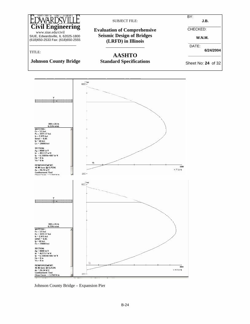
Civil Engineering www.siue.edu/civilSIUE, Edwardsville, IL 62025-1800(618)650-2533 Fax: (618)650-2555_______________________
TITLE:
Johnson County Bridge
SUBJECT FILE:
Evaluation of Comprehensive Seismic Design of Bridges
(LRFD) in Illinois___________________
AASHTOStandard Specifications
BY: _________ J.B.______
________________CHECKED: _____
W.N.M.W.N.M.________________DATE:__________
6/24/2004________________
Sheet No: 24 of 32
Johnson County Bridge – Expansion Pier
B-24

Civil Engineering www.siue.edu/civilSIUE, Edwardsville, IL 62025-1800(618)650-2533 Fax: (618)650-2555_______________________
TITLE:
Johnson County Bridge
SUBJECT FILE:
Evaluation of Comprehensive Seismic Design of Bridges
(LRFD) in Illinois___________________
AASHTOStandard Specifications
BY: _________ J.B.______
________________CHECKED: _____
W.N.M.W.N.M.________________DATE:__________
6/24/2004________________
Sheet No: 25 of 32
s 12 2⋅AbAh⋅:= s 9.538= Spacing for #5 bars.
Ah 12 2⋅.4412⋅:= Ah 0.88= ρh
Ah12 26⋅
:= ρh 0.0028=
8.18.2.3.4: spacing for "cross ties" can not be more than 24"
Cross ties will restraint the width of the wall at every third vertical in the fixed pier and every other vertical in the expansion pier. Every other row as you go up the height of the wall will be restrained in this manner. Since all bars are #10 or smaller, #4 ties are the appropriate size. The ties will have a 90 deg. hook on one end and a 180 deg. hook on the other; the ties will be continuous through the width of the pier and will alternate hook types as you go along the width or height of the wall.
An additional note: all transverse reinforcement will have a U-shaped piece spliced to each end to go around the short ends of each wall. These bars will be of the same size and spacing as the horizontal bars, and will have appropriate splice lengths.
8.25.1: ld 1.7 .04 .44⋅60000
3500⋅⎛
⎜⎝
⎞⎠
⋅:= ld 30.344= Use 31" for development length of U's
8.27.3: Use 31" for splice length of horizontal #6's
8.23.2: Hooks should have a diameter of 9" for #9 bars and 4.5" for #6 bars; these will be used with the appropriate development length to create dowels for vertical rebars
8.16.2.3.1 - Transverse Reinforcement:
ρh .0025:= Ah ρh 12⋅ 26⋅:= Ah 0.78= in2
Ab .79:= s 12 2⋅AbAh⋅:= s 24.308= Spacing for #8 bars.
Ab .60:= s 12 2⋅AbAh⋅:= s 18.462= Spacing for #7 bars.
Ab .44:= s 12 2⋅AbAh⋅:= s 13.538= Spacing for #6 bars;
Use these at 12" o.c.
Ab .31:=
B-25

Civil Engineering www.siue.edu/civilSIUE, Edwardsville, IL 62025-1800(618)650-2533 Fax: (618)650-2555_______________________
TITLE:
Johnson County Bridge
SUBJECT FILE:
Evaluation of Comprehensive Seismic Design of Bridges
(LRFD) in Illinois___________________
AASHTOStandard Specifications
BY: _________ J.B.______
________________CHECKED: _____
W.N.M.W.N.M.________________DATE:__________
6/24/2004________________
Sheet No: 26 of 32
Weak direction shear for LC2
Vs2 27:= Strong direction shear for LC2
VR1 Vw12 Vs1
2+:= VR1 105= kip
VR2 Vw22 Vs2
2+:= VR2 41= kip
Expansion Pier: We are using the same minimum amount of horizontal steel for the fixed pier as for the expansion pier; the fixed pier has higher shear forces, so this design will work for both piers.
vrVR1 1000⋅
308 26⋅:= vr 13= psi
applied shear stress at wall/pilecap connection
φvc .85vc:= φvc 101= psi
Concrete is adequate for applied shear force in the pier wall.
8.25.1: Use 18" development length for a #6 bar hook, and 41" development length for #8 bar hook.
8.23.1: Extension at free end of standard hook is 13.5" for #8 bar, and 9" for #6 bar
8.16.6.2.2 Shear Strength fc 3500:= ρh .003:= fy 60000:=
R = 1.0
Div 1A (7.6.3): vc 2 fc⋅:= vc 118= psi
Fix Pier: Vw1 105:= Weak direction shear for LC1
Vs1 8:= Strong direction shear for LC1
Vw2 31.5:=
B-26

Civil Engineering www.siue.edu/civilSIUE, Edwardsville, IL 62025-1800(618)650-2533 Fax: (618)650-2555_______________________
TITLE:
Johnson County Bridge
SUBJECT FILE:
Evaluation of Comprehensive Seismic Design of Bridges
(LRFD) in Illinois___________________
AASHTOStandard Specifications
BY: _________ J.B.______
________________CHECKED: _____
W.N.M.W.N.M.________________DATE:__________
6/24/2004________________
Sheet No: 27 of 32
8 #6's for vertical reinforcement which has a ρ = .00138; minimum is .5% (D1-A, 6.4.2(C) ).
Using PCACOL: a 18" diameter column bent about one axis, with the given loading needs:
kip ft−M 97:=
Using LPile, the forces due to the deflections were:
At around 7 kips (13 feet below the cap), the concrete alone can handle the shear, so no shear reinforcement will be needed below that point, just a minimum required for adequate lateral reinforcement, spacing will be 9" (See Division 1-A, 6.4.2(C) ).
kipsvnoshear 7=vnoshear .5 vc⋅( ) 18 14.125⋅( )1000
⋅:=
The limit for f.s = 24000 psi; so 9" pitch on a #5 spiral will work.
(8-7): psifs1 19310=fs1 vstress vc−( ) 18⋅9
.31⋅:=
The Pile requires shear reinforcement since V.stress is more than V.c
Foundation Design for Seismic:
Design of Piles (using the max deflection of cap under fixed pier):
Using SAP2000 Model we have these given deflections (inches) at the tops of the pilesdue to loading:
∆1 .189:= ∆2 .058:= ∆max ∆12⎛
⎝⎞⎠ ∆2
2⎛⎝
⎞⎠+:= ∆max 0.198= inches
From LPile: vmax 31.5:=
Shear Stress: vstressvmax
18 14.125⋅( )10001.33⋅:= vstress 93.153= psi
vc .95 3500⋅( ):= vc 56.203= psi
B-27

Civil Engineering www.siue.edu/civilSIUE, Edwardsville, IL 62025-1800(618)650-2533 Fax: (618)650-2555_______________________
TITLE:
Johnson County Bridge
SUBJECT FILE:
Evaluation of Comprehensive Seismic Design of Bridges
(LRFD) in Illinois___________________
AASHTOStandard Specifications
BY: _________ J.B.______
________________CHECKED: _____
W.N.M.W.N.M.________________DATE:__________
6/24/2004________________
Sheet No: 28 of 32
The cap is 3' thick. The pile longitudinal reinforcement will go up into the cap for a distance of 14", then the ends of the #6 bars will have 90 degree hooks with 9" extensions.
effective depth = 14.125" (controls)15 * d.b = 11.25"
for flexure:
Development Lengths:(8.24):
Use a 30" lap splice to connect two pieces of spiral together.
in12- or -
(controls) in48 db⋅ 30=Spiral Laps:
Use a #5 sprial with a 3" pitch for the first 13' of the pile below the cap and the bottom 2' feet of the pile; also continue spiral up into the cap and terminate at the tops of the verticals with an appropriate hook
(Above equation comes from Nawy page 347; it uses that fact that ρ.s is actually the volume of the spiral divided by the volume of the core concrete.)
Use #5 bars at pitch of 3".Smax 2.99=Smax4 as⋅ Dc db−( )⋅⎡⎣ ⎤⎦
Dc2ρs⋅⎛
⎝⎞⎠
:=
ρs 0.0328=ρs .45
AgAc
⎛⎜⎜⎝
⎞
⎠1−
⎡⎢⎢⎣
⎤⎥⎥⎦
⋅fcfy⋅:=(minimum)
fy 60000:=fc 3500:=Ac14π⋅ Dc
2⋅⎛⎜
⎝⎞⎠
:=Ag14π⋅ 182⋅⎛⎜
⎝⎞⎠
:=
Dc 12=Dc 18 3 2⋅( )−:=db .625:=as .31:=
(8.18.2.2):
Required Pitch Spacing with #5 bars:
B-28

Civil Engineering www.siue.edu/civilSIUE, Edwardsville, IL 62025-1800(618)650-2533 Fax: (618)650-2555_______________________
TITLE:
Johnson County Bridge
SUBJECT FILE:
Evaluation of Comprehensive Seismic Design of Bridges
(LRFD) in Illinois___________________
AASHTOStandard Specifications
BY: _________ J.B.______
________________CHECKED: _____
W.N.M.W.N.M.________________DATE:__________
6/24/2004________________
Sheet No: 29 of 32
fr 444= psi Ig 12 12 beff⋅( )⋅ 363⋅:= Ig 39544879= in4
yt 18:= in
Mcrfr Ig⋅( )yt( ):= 1.2 Mcr⋅( ) 1
12000⋅ 97479= k ft−
Rcr1.2 Mcr⋅( )
.9 26⋅ 12⋅ 322⋅( ):= Rcr 4068= psi
This number is off the charts; but it is permissible to waive this requirement if a 33% increase in the required area of steel is provided.
As .0025 12⋅ 32⋅( ) 1.33⋅:= As 1.277=in2
ftUse # 6 bars at 4" o.c. for transverse reinforcement
Asl .0018 12⋅ 32⋅( ):= Asl 0.691=in2
ft
Use #6 bars at 7.5" o.c. for longitudinal reinforcement
Pile cap: Moment:
Mu 3465:= k ft−
(IDOT Bridge Manual 3.7.5)beff .8 2.67⋅( ) 3.75+:= beff 5.89= ft
(actual spacing = 7.5'; so 5.89' controls)
RMu 12000⋅( )
.9 26⋅ 12⋅ 322⋅( ):= R 145= psi
ω .0025600003500
⎛⎜⎝
⎞⎠
⋅:= Rd ω 3500⋅ 1 .59 ω⋅−( )⋅:= Rd 146.207= psi
As .0025 12⋅ 32⋅( ):= As 0.96=in2
ftof footing (transverse steel)
Transverse rebar for footing is chosen to be #6 bars @ 5.5" o.c.
8.17.1.1:
fr 7.5 3500⋅:=
B-29

Civil Engineering www.siue.edu/civilSIUE, Edwardsville, IL 62025-1800(618)650-2533 Fax: (618)650-2555_______________________
TITLE:
Johnson County Bridge
SUBJECT FILE:
Evaluation of Comprehensive Seismic Design of Bridges
(LRFD) in Illinois___________________
AASHTOStandard Specifications
BY: _________ J.B.______
________________CHECKED: _____
W.N.M.W.N.M.________________DATE:__________
6/24/2004________________
Sheet No: 30 of 32
Pile cap works in two-way shear.
psivc 53=
psiv2way 35=v2way236 1000⋅( )
bo 32⋅( )1
1.33⋅:=
inbo 157=bo π 2⋅ 9 16+( )⋅:=
(8.15.5.6): Two-Way
Pile cap works in one-way shear.
psivc 53=vc .9 3500⋅( ):=
psiv 39=v.5 236⋅ 1000⋅( )12 beff⋅ 32⋅( )
11.33⋅:=(8.15.5) &
(8.15.5.6):
Pile center is located directly over critical section; thus according to 4.4.11.3.2: we use interpolation and find that 1/2 of reaction is used in this shear check.
inlcs 0.0=lcs 3.75 12⋅( ) 13− 32−:=Location of critical sectionwith respect to pile center:
d.p = 18" d = 32"(4.4.11.3):
(8.15.5.6): One-WayShear:
B-30

Civil Engineering www.siue.edu/civilSIUE, Edwardsville, IL 62025-1800(618)650-2533 Fax: (618)650-2555_______________________
TITLE:
Johnson County Bridge
SUBJECT FILE:
Evaluation of Comprehensive Seismic Design of Bridges
(LRFD) in Illinois___________________
AASHTOStandard Specifications
BY: _________ J.B.______
________________CHECKED: _____
W.N.M.W.N.M.________________DATE:__________
6/24/2004________________
Sheet No: 31 of 32
1.33As2 fy⋅( )
FS⋅
11000⋅ 77= kips
We need 3 (or 4) #6 bar dowels of appropriate length to resist pullout failure
8.25.1:
ld .04 .44⋅60000
3500⋅:= ld 17.85= in
8.25.3.3:
.75 ld⋅ 13.387= Use a development length of 13.5" into the main part of the pile for the #6 dowels
8.29.2:
lhb 1200.750
3500⋅:= lhb 15.213= in
The #6 dowels and #6 verticals will terminate in the slab with an L(hb) of 11", and a 90 degree hook with a 9" extension. 8.29.3.2: .7 lhb⋅ 10.649=
Pullout of Piles in Tension:
As 8 .44⋅:= As 3.52= in2
fy 24000:=
FS 2:= (Also: 33% increase in allowable stresses)
1.33 As fy⋅( ) 11000⋅
FS56= kips (Allowable Uplift of a Single Pile)
Fuplift58.8
:= (Divide Ultimate Load by R = .8 for connections)
Fuplift 73= kips (Largest Uplift Force on a Single Pile)
As2 11 .44⋅:= As2 4.84= in2
B-31
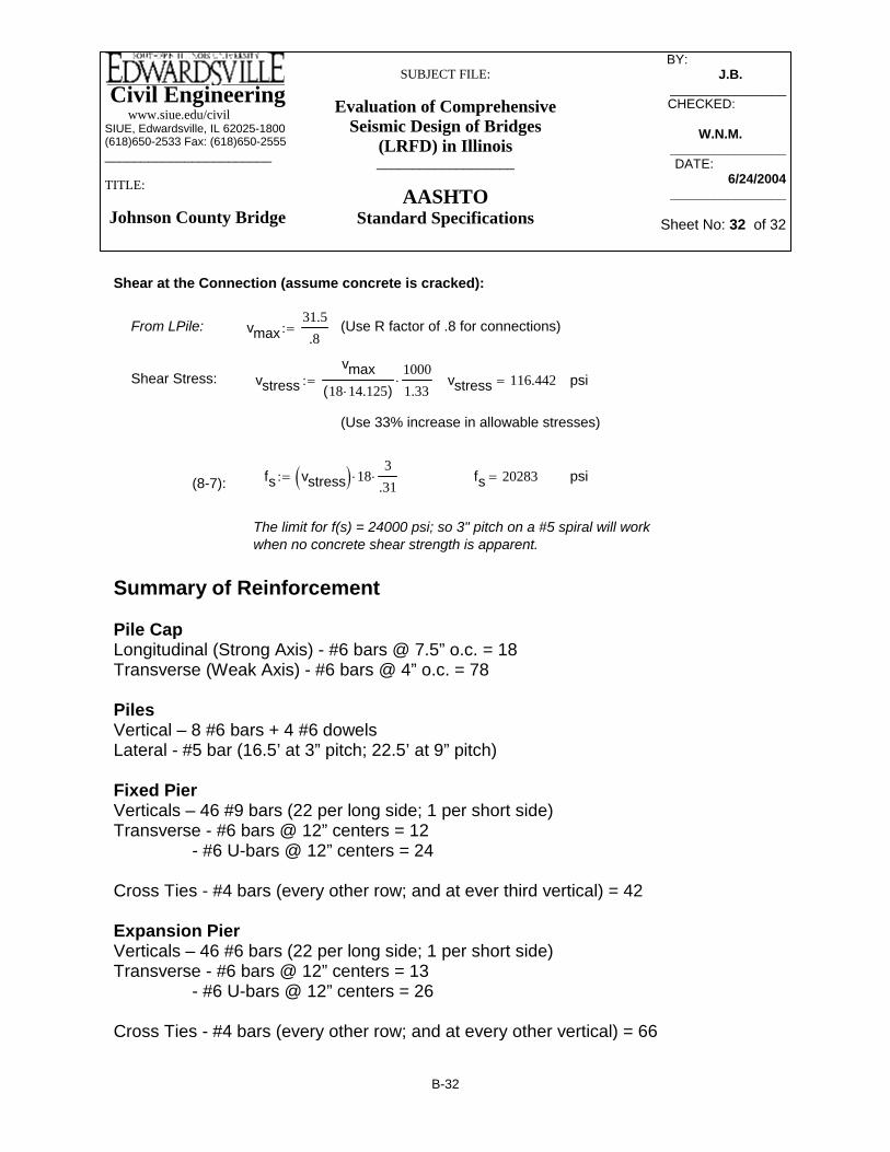
Civil Engineering www.siue.edu/civilSIUE, Edwardsville, IL 62025-1800(618)650-2533 Fax: (618)650-2555_______________________
TITLE:
Johnson County Bridge
SUBJECT FILE:
Evaluation of Comprehensive Seismic Design of Bridges
(LRFD) in Illinois___________________
AASHTOStandard Specifications
BY: _________ J.B.______
________________CHECKED: _____
W.N.M.W.N.M.________________DATE:__________
6/24/2004________________
Sheet No: 32 of 32
Shear at the Connection (assume concrete is cracked):
From LPile: vmax31.5.8
:= (Use R factor of .8 for connections)
Shear Stress: vstressvmax
18 14.125⋅( )10001.33⋅:= vstress 116.442= psi
(Use 33% increase in allowable stresses)
fs vstress( ) 18⋅3
.31⋅:= fs 20283= psi(8-7):
The limit for f(s) = 24000 psi; so 3" pitch on a #5 spiral will work when no concrete shear strength is apparent.
Summary of Reinforcement Pile Cap Longitudinal (Strong Axis) - #6 bars @ 7.5” o.c. = 18 Transverse (Weak Axis) - #6 bars @ 4” o.c. = 78 Piles Vertical – 8 #6 bars + 4 #6 dowels Lateral - #5 bar (16.5’ at 3” pitch; 22.5’ at 9” pitch) Fixed Pier Verticals – 46 #9 bars (22 per long side; 1 per short side) Transverse - #6 bars @ 12” centers = 12
- #6 U-bars @ 12” centers = 24 Cross Ties - #4 bars (every other row; and at ever third vertical) = 42 Expansion Pier Verticals – 46 #6 bars (22 per long side; 1 per short side) Transverse - #6 bars @ 12” centers = 13
- #6 U-bars @ 12” centers = 26 Cross Ties - #4 bars (every other row; and at every other vertical) = 66
B-32

Civil Engineering www.siue.edu/civilSIUE, Edwardsville, IL 62025-1800(618)650-2533 Fax: (618)650-2555_______________________
TITLE:Saint Clair County Bridge
SUBJECT FILE:
Evaluation of Comprehensive Seismic Design of Bridges
(LRFD) in Illinois___________________
NCHRP Guidelines
BY:_____________ NA________
____________________CHECKED: _____
AAA_______ ____________________
DATE:__________ 6/22/2004
___________________
Sheet No: 1 of __
Appendix C -- Detailed Computations for Seismic Analysis and Design of the St. Clair County Bridge using Proposed NCHRP Specification
C-1

Civil Engineering www.siue.edu/civilSIUE, Edwardsville, IL 62025-1800(618)650-2533 Fax: (618)650-2555_______________________
TITLE:Saint Clair County Bridge
SUBJECT FILE:
Evaluation of Comprehensive Seismic Design of Bridges
(LRFD) in Illinois___________________
NCHRP Guidelines
BY:_____________ NA________
____________________CHECKED: _____
AAA_______ ____________________
DATE:__________ 6/22/2004
___________________
Sheet No: 2 of __
Table of contents of Appendix-C Section Properties of Superstructure........................................................................C-3
• Moment inertia for superstructure....................................................................C-3
• Torsional properties.........................................................................................C-5
• Cross sectional Area........................................................................................C-5
• Load calculation.............................................................................................. C-6 Design Response Spectrum.......................................................................................C-8 SAP 2000 Model.........................................................................................................C-12
• Modal participating Mass Ratios.....................................................................C-13 Pile Stiffness................................................................................................................C-14 Column Design............................................................................................................C-18
• Forces and Moments........................................................................................C-19
• PCACOL results...............................................................................................C-21
• Transverse reinforcement.................................................................................C-22 Connection Design......................................................................................................C-33
• Column-Cap beam connection.........................................................................C-33
• Column-Footing connection.............................................................................C-38 Footing Design.............................................................................................................C-44 Cap Beam Design........................................................................................................C-63 Drawings......................................................................................................................C-70
C-2

Civil Engineering www.siue.edu/civilSIUE, Edwardsville, IL 62025-1800(618)650-2533 Fax: (618)650-2555_______________________
TITLE:Saint Clair County Bridge
SUBJECT FILE:
Evaluation of Comprehensive Seismic Design of Bridges
(LRFD) in Illinois___________________
NCHRP Guidelines
BY:_____________ NA________
____________________CHECKED: _____
AAA_______ ____________________
DATE:__________ 6/22/2004
___________________
Sheet No: 3 of __
nEsEc
:= n 8.624= Modular Ratio
boltD 24 10 3−( )⋅ inch⋅:= boltD 0.945= Bolt Diameter (in.)
Skew 263160
⎛⎜⎝
⎞⎠
+40
3600⎛⎜⎝
⎞⎠
+:= Skew 26.528= Skew Angle (degrees)
Calculations for Moment of Inertia for Superstructure
Leff 41.50 inch⋅:= Leff 1.634 103×= Effective length of a span (in)
tavg .195 inch⋅:= tavg 7.677= Slab thickness (in)
tw .014 inch⋅:= tw 0.551= Web thickness (in)
bf1 .300 inch⋅:= bf1 11.811= Top flange width outerline (in)
bf2 .600 inch⋅:= bf2 23.622= Top flange width innerline (in)
gspace 1.905 inch⋅:= gspace 75= Girderline spacing (in)
Pertinent Information about Materials used, etc. :
pconv 1.45 10 4−×( ):= This is the N/m^2 to psi conversion factor.
feet1
.3048:= feet 3.281= This is the meter to feet conversion.
inch feet 12⋅:= inch 39.37= This will convert meters to inches.
fc 24 106( )⋅ pconv⋅:= fc 3480.000=
fy 400 106( )⋅ pconv⋅:= fy 5.8 104×= Reinforcement( ) psi( )
Fy1 345 106( ) pconv⋅:= Fy1 5.003 104×= Structural( ) psi( )
Fy2 250 106( )⋅ pconv⋅:= Fy2 3.625 104×= Structural( ) psi( )
Ec 57000 fc( )⋅:= Ec 3.363 106×= Modulus of Elasticity of concrete.
Es 29000000:= Es 2.9 107×= Modulus of Elasticity of steel.
C-3

Civil Engineering www.siue.edu/civilSIUE, Edwardsville, IL 62025-1800(618)650-2533 Fax: (618)650-2555_______________________
TITLE:Saint Clair County Bridge
SUBJECT FILE:
Evaluation of Comprehensive Seismic Design of Bridges
(LRFD) in Illinois___________________
NCHRP Guidelines
BY:_____________ NA________
____________________CHECKED: _____
AAA_______ ____________________
DATE:__________ 6/22/2004
___________________
Sheet No: 4 of __
efw5 204.232=
efw6 6 tavg⋅( ) .5 tw⋅( )+:= efw6 46.339=
efw7 6 tavg⋅( ) .25 bf1⋅( )+:= efw7 49.016=
efw8 6 tavg⋅( ) .25 bf2⋅( )+:= efw8 51.969=
ohw .925 inch⋅:= ohw 36.417= This controls
EFWoutside .5 EFWinside⋅( ) ohw+:= EFWoutside 73.917=
We can use all of the slab for moment of inertia.
For Moment of Inertia Calculations of the superstructure.
Iyy1 36.2084:= Izz1 3676.5792:=
Iyy2 61.4485:= Izz2 5343.1700:=
1. Effective Flange Width of interior maybe be taken as least of:
efw1 .25 Leff⋅:= efw1 408.465=
efw2 12 tavg⋅( ) tw+:= efw2 92.677=
efw3 12tavg( ) .5 bf1⋅( )+:= efw3 98.031= outer( )
efw3b 12 tavg⋅( ) .5 bf2⋅( )+:= efw3b 103.937= inner( )
efw4 gspace:= efw4 75= This controls
EFWinside gspace:= EFWinside 75=
2. Effective Flange Width of exterior maybe be taken as .5 EFW plus least of:
efw518
Leff⋅:=
C-4
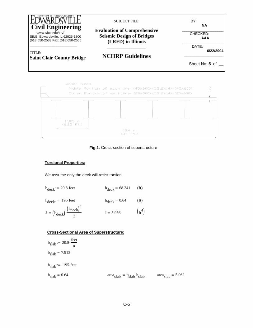
Civil Engineering www.siue.edu/civilSIUE, Edwardsville, IL 62025-1800(618)650-2533 Fax: (618)650-2555_______________________
TITLE:Saint Clair County Bridge
SUBJECT FILE:
Evaluation of Comprehensive Seismic Design of Bridges
(LRFD) in Illinois___________________
NCHRP Guidelines
BY:_____________ NA________
____________________CHECKED: _____
AAA_______ ____________________
DATE:__________ 6/22/2004
___________________
Sheet No: 5 of __
areaslab 5.062=areaslab hslab bslab⋅:=hslab 0.64=
hslab .195 feet⋅:=
bslab 7.913=
bslab 20.8feetn
⋅:=
Cross-Sectional Area of Superstructure:
ft4( )J 5.956=J bdeck( )hdeck( )3
3⋅:=
ft( )hdeck 0.64=hdeck .195 feet⋅:=
ft( )bdeck 68.241=bdeck 20.8 feet⋅:=
We assume only the deck will resist torsion.
Torsional Properties:
Fig.1. Cross-section of superstructure
C-5

Civil Engineering www.siue.edu/civilSIUE, Edwardsville, IL 62025-1800(618)650-2533 Fax: (618)650-2555_______________________
TITLE:Saint Clair County Bridge
SUBJECT FILE:
Evaluation of Comprehensive Seismic Design of Bridges
(LRFD) in Illinois___________________
NCHRP Guidelines
BY:_____________ NA________
____________________CHECKED: _____
AAA_______ ____________________
DATE:__________ 6/22/2004
___________________
Sheet No: 6 of __
wslab 19.05 feet⋅( ) .195 feet⋅( )⋅ 150⋅:= wslab 5998= plf
wgirder1 11 1.372 feet⋅( ) .014 feet⋅( )⋅ .020 feet⋅( ) .900 feet⋅( )⋅+[ ] 490⋅:=
wgirder2 11 1.372 feet⋅( ) .014 feet⋅( ) .045 feet⋅( ) 1.200 feet⋅( )⋅+[ ] 490⋅:=
wgirder1 2159= plf
wgirder2 4247= plf
wmedian areamedian .190⋅:= wmedian 0.389= plf
Interior Cross-frames: 2 - L4x4x5/16 @ 2546 mm
1 - L4x4x5/16 @ 1904 mm
weight(lb.) per linear foot = 8.16
10 spaces underneath bridge 13 cross frames per length total number = 130
areagirder1 11 .02 .3⋅( ) .02 .6⋅( )+ 1.372 .014⋅( )+[ ]⋅ feet⋅ feet⋅:= areagirder1 4.406=
areagirder2 11 .045 .6⋅( ) .045 .6⋅( )+ 1.372 .014⋅( )+[ ]⋅ feet⋅ feet⋅:= areagirder2 8.668=
areasuper1 areaslab areagirder1+( ):= areasuper1 9.468= ft2
areasuper2 areaslab areagirder2+( ):= areasuper2 13.73= ft2
areabarrier .2 .535⋅( ) .065 .535⋅( )+ .320 .330⋅( )+ .5 .180⋅ .330⋅( )+[ ] feet⋅ feet⋅:= areabarrier 2.982=
areamedian .1501.3 1.236+( )
2⎡⎢⎣
⎤⎥⎦
⋅⎡⎢⎣
⎤⎥⎦
feet⋅ feet⋅:= areamedian 2.047=
Loads :
Dead Loads of the superstructure
wbarrier 2 areabarrier⋅ 150⋅:= wbarrier 895= plf
C-6

Civil Engineering www.siue.edu/civilSIUE, Edwardsville, IL 62025-1800(618)650-2533 Fax: (618)650-2555_______________________
TITLE:Saint Clair County Bridge
SUBJECT FILE:
Evaluation of Comprehensive Seismic Design of Bridges
(LRFD) in Illinois___________________
NCHRP Guidelines
BY:_____________ NA________
____________________CHECKED: _____
AAA_______ ____________________
DATE:__________ 6/22/2004
___________________
Sheet No: 7 of __
W(outer) is the uniform dead load along the superstructure from the abutments to the place where the field splices are located. W(inner) occupy the center of each girderline which are the continuous part over the central pier.
plfwinner 14288=winner wbarrier wmedian+ wcframe+ wslab+ wgirder2+ wfws+:=
plfwouter 12199=wouter wbarrier wmedian+ wcframe+ wslab+ wgirder1+ wfws+:=
Adding the individual pieces together we get:
plfwfws 3.058 103×=wfws 2.4 1000⋅ pconv⋅ 144⋅ wbridge⋅:=
ftwbridge 61.024=wbridge 3 4.2+ .3+ 3.9+ 4.2+ 3+( ) feet⋅:=
Future Wearing Surface was 2.4 kN/m^2 or about 50 psf.
plfwcframe 89.516=wcframe 13 10⋅ 2.546 2.546+ 1.904+( ) feet⋅[ ]⋅8.16272
⋅:=
C-7

Civil Engineering www.siue.edu/civilSIUE, Edwardsville, IL 62025-1800(618)650-2533 Fax: (618)650-2555_______________________
TITLE:Saint Clair County Bridge
SUBJECT FILE:
Evaluation of Comprehensive Seismic Design of Bridges
(LRFD) in Illinois___________________
NCHRP Guidelines
BY:_____________ NA________
____________________CHECKED: _____
AAA_______ ____________________
DATE:__________ 6/22/2004
___________________
Sheet No: 8 of __
Period at the end of construction design spectral acceleration plateau TSSD1SDS
:=
0.4 SDS⋅ 0.326=
Design earthquake response spectral acceleration at long periodSD1 0.394=
SD1 Fv S1⋅:=
Design earthquake response spectral acceleration at short periodSDS 0.814=
SDS Fa Ss⋅:=
Site coefficient for long periodFv 2.0:=
Site coefficient for short period Fa 1.3:=
1-second period spectral accelerationS1 0.196946:=
0.2-second period spectral accelerationSs 0.6261940:=
Using USGS website to find probalistic ground motion values, in %g, at nearest grid point area (2% PE in 50 year):
- Design Response Spectrum Development - MCE
AASHTO Table 3.5.1s 1.5:=
Type III per AASHTO Spec.
SDAP = D
SDR = 6
(MCEER Guide Spec. 3.4.2.1) Site Class D
Site Class = Medium Stiff Clay
Response Spectrum:
C-8

Civil Engineering www.siue.edu/civilSIUE, Edwardsville, IL 62025-1800(618)650-2533 Fax: (618)650-2555_______________________
TITLE:Saint Clair County Bridge
SUBJECT FILE:
Evaluation of Comprehensive Seismic Design of Bridges
(LRFD) in Illinois___________________
NCHRP Guidelines
BY:_____________ NA________
____________________CHECKED: _____
AAA_______ ____________________
DATE:__________ 6/22/2004
___________________
Sheet No: 9 of __
0.4 SDS_fe⋅ 0.043=
Design earthquake response spectral acceleration at long periodSD1_fe 0.036=
SD1_fe Fv_fe S1_fe⋅:=
Design earthquake response spectral acceleration at short periodSDS_fe 0.108=
SDS_fe Fa_fe Ss_fe⋅:=
Site coefficient for long periodFv_fe 2.4:=
Site coefficient for short period Fa_fe 1.6:=
1-second period spectral accelerationS1_fe 0.01485:=
0.2-second period spectral accelerationSs_fe 0.06763:=
Using USGS website to find probalistic ground motion values, in %g, at nearest grid point area (2% PE in 50 year):
- Design Response Spectrum Development - MCE
- Design Response Spectrum Development - FE
Seismic Hazard Level IV (Guide Spec. Table 3.7-1)
0.6<Fa.Ss Fa Ss⋅ 0.814=
SecT0 0.097=
Period at the beginning of construction design spectral acceleration plateauT0 0.2 TS⋅:=
SecTS 0.484=
C-9

Civil Engineering www.siue.edu/civilSIUE, Edwardsville, IL 62025-1800(618)650-2533 Fax: (618)650-2555_______________________
TITLE:Saint Clair County Bridge
SUBJECT FILE:
Evaluation of Comprehensive Seismic Design of Bridges
(LRFD) in Illinois___________________
NCHRP Guidelines
BY:_____________ NA________
____________________CHECKED: _____
AAA_______ ____________________
DATE:__________ 6/22/2004
___________________
Sheet No: 10 of __
TS_feSD1_feSDS_fe
:= Period at the end of construction design spectral acceleration plateau
TS_fe 0.329= Sec
T0_fe 0.2 TS_fe⋅:= Period at the beginning of construction design spectral acceleration plateau
T0_fe 0.066= Sec
Fa_fe Ss_fe⋅ 0.108= Fa_fe Ss_fe⋅ 0.15≤
Fv_fe S1_fe⋅ 0.036= Fv_fe S1_fe⋅ 0.15≤
Seismic Hazard Level I (Guide Spec. Table 3.7-1)
0
0.1
0.2
0.3
0.4
0.5
0.6
0.7
0.8
0.9
0 0.5 1 1.5 2 2.5 3
Period (T)
Resp
onse
spe
ctru
m (F
ract
ion
of g
)
MCEFE
Graph 1. response Spectrum (MCE and FE)
C-10

Civil Engineering www.siue.edu/civilSIUE, Edwardsville, IL 62025-1800(618)650-2533 Fax: (618)650-2555_______________________
TITLE:Saint Clair County Bridge
SUBJECT FILE:
Evaluation of Comprehensive Seismic Design of Bridges
(LRFD) in Illinois___________________
NCHRP Guidelines
BY:_____________ NA________
____________________CHECKED: _____
AAA_______ ____________________
DATE:__________ 6/22/2004
___________________
Sheet No: 11 of __
Rcol 0.849:=So
okRB< Rcol 0.849=
Response Modification Factor for substructure [MCEER Giude Spec.(4.7.1)]
Rcol 1 RB 1−( ) T1.25 TS⋅
+:=
Base Response Modification Factor for substructure [MCEER Giude Spec. (Table 4.7.1)]
RB 0.9:=
Period of vibration of BridgeT 0.62169:=
TS 0.329:=
Response Modification Factor for FE:
Rcol 1.5:=So
RB< Rcol 1.638=
Response Modification Factor for substructure [MCEER Giude Spec.(4.7.1)]
Rcol 1 RB 1−( ) T1.25 TS⋅
+:=
Base Response Modification Factor for substructure [MCEER Giude Spec. (Table 4.7.1)]
RB 1.5:=
Period of vibration of BridgeT 0.7720:=
TS 0.484=
Response Modification Factor for MCE:
C-11

Civil Engineering www.siue.edu/civilSIUE, Edwardsville, IL 62025-1800(618)650-2533 Fax: (618)650-2555_______________________
TITLE:Saint Clair County Bridge
SUBJECT FILE:
Evaluation of Comprehensive Seismic Design of Bridges
(LRFD) in Illinois___________________
NCHRP Guidelines
BY:_____________ NA________
____________________CHECKED: _____
AAA_______ ____________________
DATE:__________ 6/22/2004
___________________
Sheet No: 12 of __
SAP 2000 model:
Fig.2.SAP modeling of Saint Clair Bridge with section extrution.
Fig.3.First Mode shape, longitudinal direction ( T=0.77220 Sec)
C-12

Civil Engineering www.siue.edu/civilSIUE, Edwardsville, IL 62025-1800(618)650-2533 Fax: (618)650-2555_______________________
TITLE:Saint Clair County Bridge
SUBJECT FILE:
Evaluation of Comprehensive Seismic Design of Bridges
(LRFD) in Illinois___________________
NCHRP Guidelines
BY:_____________ NA________
____________________CHECKED: _____
AAA_______ ____________________
DATE:__________ 6/22/2004
___________________
Sheet No: 13 of __
Fig.4.Third Mode shape, Transvers direction ( T=0.55756 sec)
TABLE: Modal Participating Mass RatiosOutputCase StepType StepNum Period UX UY UZ UX UY UZ
Text Text Unitless Sec Unitless Unitless Unitless Percentage Unitless UnitlessEIGENMODES Mode 1 0.772195 0.4289 0.1159 1.62E-18 42.89 11.59 0.00EIGENMODES Mode 2 0.596676 0.017 0.0066 3.524E-19 1.70 0.66 0.00EIGENMODES Mode 3 0.557558 0.1943 0.7253 9.831E-17 19.43 72.53 0.00EIGENMODES Mode 4 0.360047 3.623E-17 2.49E-16 0.3208 0.00 0.00 32.08EIGENMODES Mode 5 0.233051 0.000544 0.1019 3.783E-18 0.05 10.19 0.00EIGENMODES Mode 6 0.22987 0.3592 0.0503 4.816E-19 35.92 5.03 0.00EIGENMODES Mode 7 0.198011 2.469E-16 9.885E-17 1.47E-16 0.00 0.00 0.00EIGENMODES Mode 8 0.152639 7.672E-20 4.402E-20 6.566E-19 0.00 0.00 0.00EIGENMODES Mode 9 0.148196 0.00002595 0.000006588 3.132E-16 0.00 0.00 0.00EIGENMODES Mode 10 0.118068 1.01E-17 1.422E-17 0.0612 0.00 0.00 6.12EIGENMODES Mode 11 0.1008 0.000000403 0.00004337 7.727E-15 0.00 0.00 0.00EIGENMODES Mode 12 0.073461 1.26E-15 6.781E-16 0.5236 0.00 0.00 52.36EIGENMODES Mode 13 0.070734 1.663E-07 3.788E-08 5.893E-13 0.00 0.00 0.00EIGENMODES Mode 14 0.0583 1.18E-16 2.771E-17 0.0927 0.00 0.00 9.27EIGENMODES Mode 15 0.050561 3.263E-16 1.444E-16 0.00002029 0.00 0.00 0.00EIGENMODES Mode 16 0.048321 4.589E-12 1.788E-08 2.25E-12 0.00 0.00 0.00EIGENMODES Mode 17 0.030654 0.000000766 1.412E-07 3.277E-11 0.00 0.00 0.00EIGENMODES Mode 18 0.028907 1.235E-09 1.008E-09 8.313E-14 0.00 0.00 0.00EIGENMODES Mode 19 0.027706 9.583E-16 7.176E-16 6.679E-13 0.00 0.00 0.00EIGENMODES Mode 20 0.025344 1.781E-17 4.69E-16 0.0016 0.00 0.00 0.16
100.00 100.01 99.99
Table.1.Modal Participating Mass Ratios
C-13

Civil Engineering www.siue.edu/civilSIUE, Edwardsville, IL 62025-1800(618)650-2533 Fax: (618)650-2555_______________________
TITLE:Saint Clair County Bridge
SUBJECT FILE:
Evaluation of Comprehensive Seismic Design of Bridges
(LRFD) in Illinois___________________
NCHRP Guidelines
BY:_____________ NA________
____________________CHECKED: _____
AAA_______ ____________________
DATE:__________ 6/22/2004
___________________
Sheet No: 14 of __
Ktran_single 437.143=
Ktran_single 51121.4⋅:=
ftL 80.417:=
kft
Kx 9.45 104×=
Kx Klong_single N⋅:=
kft
Klong_single 900=
P-Y Curve (Kips vs.inches)
0
10
20
30
40
50
60
70
80
0 0.2 0.4 0.6 0.8 1 1.2 1.4
Klong_single 4512.6⋅:=
21X5 (75" in long and 75" spacing in transverse direction)N 105:=
ksfE29000000 144⋅
1000:=
Use HP 14X117 for the NCHRP designA=34.4 in^2Ixx=1220 in^4 Zxx=194 in^3Iyy=443 in^4 Zyy=91.4 in^3Depth=14.2 inWidth=14.9 in
AASHTO LRFD 6.5.4.2φc 0.9:=
Compressive resistanceAASHTO LRFD, 6.9.2.1&2
.9 φ⋅ Fy⋅ An⋅Tension
.9 φ⋅ Fy⋅ Ag⋅Compression
Maximum Allowable Driving Loads (driven piles)AASHTO LRFD, 10.7.1.16
Group Pile Spring Stiffness (roller at abutments in transverse direction)
C-14

Civil Engineering www.siue.edu/civilSIUE, Edwardsville, IL 62025-1800(618)650-2533 Fax: (618)650-2555_______________________
TITLE:Saint Clair County Bridge
SUBJECT FILE:
Evaluation of Comprehensive Seismic Design of Bridges
(LRFD) in Illinois___________________
NCHRP Guidelines
BY:_____________ NA________
____________________CHECKED: _____
AAA_______ ____________________
DATE:__________ 6/22/2004
___________________
Sheet No: 15 of __
Kz 1.303 106×=
Ky 4.59 104×=
Kx 9.45 104×=
KrzKrx
Kaxial
⎛⎜⎝
⎞
⎠
KryKaxial
⎛⎜⎝
⎞
⎠+
⎡⎢⎣
⎤⎥⎦
Klong_single Ktran_single+( )2
⋅:=
Kry Kaxial S2⋅:=
S22
144N5⋅ 1 752
⋅ 2 752⋅+( )⋅:=Krx Kaxial S1⋅:=
S110144
1 75⋅( )2 2 75⋅( )2+ 3 75⋅( )2
+ 4 75⋅( )2+ 5 75⋅( )2
+ 6 75⋅( )2+ 7 75⋅( )2
+ 8 75⋅( )2+ 9 75⋅( )2
+ 10 75⋅( )2+⎡⎣ ⎤⎦⋅:=
kft
Kz 1.303 106×=
Kz Kaxial N⋅:=
kft
Kaxial 1.241 104×=
Kaxial AEL⋅:=
ft2A 0.239=
A34.4144
:=
kft
Ky 4.59 104×= P-Y Curve (Kips vs. inches)
0
10
20
30
40
50
60
0 0.2 0.4 0.6 0.8 1 1.2 1.4
Ky Ktran_single N⋅:=
C-15

Civil Engineering www.siue.edu/civilSIUE, Edwardsville, IL 62025-1800(618)650-2533 Fax: (618)650-2555_______________________
TITLE:Saint Clair County Bridge
SUBJECT FILE:
Evaluation of Comprehensive Seismic Design of Bridges
(LRFD) in Illinois___________________
NCHRP Guidelines
BY:_____________ NA________
____________________CHECKED: _____
AAA_______ ____________________
DATE:__________ 6/22/2004
___________________
Sheet No: 16 of __
k in−M2 2950:=inDisT 1.18:=
k in−M1 2830:=inDisL .5:=
kips Almost equal to P1 say OKPal 309.6=
Pal A 9⋅ 144⋅:=
kipsP1 211.246=
P1VN
Mlong2 75⋅
12 S2⋅⋅+ Mtran
10 75⋅
12 S1⋅⋅+:=
k ft−Mtran 81932:=
k ft−Mlong 57415:=
kipsV 3295:=
N 105=
kipsCap 2.15 103×=
Cap A 9000⋅:=
Axial capacity (IDOT Bridge Manual 3.8.1) = 9000 psi
Total DL = 3295 kips
Krz 1.038 108×=
Kry 6.106 107×=
Krx 1.866 109×=
C-16

Civil Engineering www.siue.edu/civilSIUE, Edwardsville, IL 62025-1800(618)650-2533 Fax: (618)650-2555_______________________
TITLE:Saint Clair County Bridge
SUBJECT FILE:
Evaluation of Comprehensive Seismic Design of Bridges
(LRFD) in Illinois___________________
NCHRP Guidelines
BY:_____________ NA________
____________________CHECKED: _____
AAA_______ ____________________
DATE:__________ 6/22/2004
___________________
Sheet No: 17 of __
P10.85 50⋅ 34.4⋅
89
M150 194⋅
M250 91.4⋅
+⎛⎜⎝
⎞⎠
⋅+ 0.978=
inDisT 1.55:=k in−M4 3560:=
k in−M3 2350:=inDisL .39:=
Fig 5. Piles Arrangement
kipsP2 187.087=
P2VN
Mlong2 75⋅
12S2⋅+ Mtran
10 75⋅
12S1⋅+:=
k ft−Mtran 107000:=
k ft−Mlong 43800:=
EQ in transverse direction
C-17

Civil Engineering www.siue.edu/civilSIUE, Edwardsville, IL 62025-1800(618)650-2533 Fax: (618)650-2555_______________________
TITLE:Saint Clair County Bridge
SUBJECT FILE:
Evaluation of Comprehensive Seismic Design of Bridges
(LRFD) in Illinois___________________
NCHRP Guidelines
BY:_____________ NA________
____________________CHECKED: _____
AAA_______ ____________________
DATE:__________ 6/22/2004
___________________
Sheet No: 18 of __
P20.85 50⋅ 34.4⋅
89
M350 194⋅
M450 91.4⋅
+⎛⎜⎝
⎞⎠
⋅+ 1.036=
M o m en t= 2350 k ip -in fo r D isp lacem en t = 0 .39 in
M o m en t= 2830 k ip -in fo r D isp lacem en t = 0 .50 in
M o m en t= 2950 k ip -in fo r D isp lacem en t = 1 .18 in
M o m en t= 3560 k ip -in fo r D isp lacem en t = 1 .55 in
C-18

Civil Engineering www.siue.edu/civilSIUE, Edwardsville, IL 62025-1800(618)650-2533 Fax: (618)650-2555_______________________
TITLE:Saint Clair County Bridge
SUBJECT FILE:
Evaluation of Comprehensive Seismic Design of Bridges
(LRFD) in Illinois___________________
NCHRP Guidelines
BY:_____________ NA________
____________________CHECKED: _____
AAA_______ ____________________
DATE:__________ 6/22/2004
___________________
Sheet No: 19 of __
Forces and Moments from SAP2000 (MCE):
Shear 2 Shear 3 Moment 2 Moment 3 Axial kips kips kip-ft kip-ft kips
top 347 609 5053 1494 833bottom 350 628 2572 5788 833
top 347 790 7339 1496 416bottom 350 810 2521 5790 416
top 347 811 7605 1496 0bottom 350 830 2002 5574 0
Shear 2 Shear 3 Moment 2 Moment 3 Axial kips kips kip-ft kip-ft kips
top 456 461 3831 1967 628bottom 460 476 1949 7624 628
top 456 599 5564 1971 314bottom 460 614 1911 7626 314
top 456 615 5766 1971 0bottom 460 630 1517 7342 0
Location
Exterior Column
Central Column
Middle Column
NCHRPForces & Moments-Trans(Y) EQ
100%Trans+40%Long
Forces & Moments-Long(X) EQ
Central Column
Exterior Column
Location
NCHRP100%Long+40%Trans
Middle Column
Final Forces and Moments due to MCE and DL by appliying Reduction Factor of 1.5 for designing columns:
Shear 2 Shear 3 Moment 2 Moment 3 Axial Shear 2 Shear 3 Moment 2 Moment 3 Axial kips kips kip-ft kip-ft kips kips kips kip-ft kip-ft kips
top 231 406 3369 996 1072 304 307 2554 1311 936bottom 233 419 1715 3859 1100 307 317 1299 5083 964
top 231 527 4893 997 794 304 399 3709 1314 726bottom 233 540 1681 3860 822 307 409 1274 5084 754
top 231 541 5070 997 517 304 410 3844 1314 517bottom 233 553 1335 3716 545 307 420 1011 4895 545
Exterior Column
Central Column
Middle Column
LongitudinalFinal Design Forces and Moments (EQ+DL) By R=1.5
NCHRP - MCETransvers
Location
C-19

Civil Engineering www.siue.edu/civilSIUE, Edwardsville, IL 62025-1800(618)650-2533 Fax: (618)650-2555_______________________
TITLE:Saint Clair County Bridge
SUBJECT FILE:
Evaluation of Comprehensive Seismic Design of Bridges
(LRFD) in Illinois___________________
NCHRP Guidelines
BY:_____________ NA________
____________________CHECKED: _____
AAA_______ ____________________
DATE:__________ 6/22/2004
___________________
Sheet No: 20 of __
Forces and Moments from SAP2000 (FE):
Shear 2 Shear 3 Moment 2 Moment 3 Axial kips kips kip-ft kip-ft kips
top 16 32 273 65 43bottom 16 34 137 143 43
top 16 41 395 65 22bottom 16 43 135 263 22
top 16 43 409 65 0bottom 16 45 134 263 0
Shear 2 Shear 3 Moment 2 Moment 3 Axial kips kips kip-ft kip-ft kips
top 31 37 312 131 48bottom 31 38 159 216 48
top 31 48 455 131 25bottom 31 49 156 516 25
top 31 50 470 131 0bottom 31 51 155 516 0
NCHRP - FEForces & Moments-Trans(Y) EQ
100%Trans+40%Long
Location
Exterior Column
Central Column
NCHRP - FEForces & Moments-Long(X) EQ
100%Long+40%Trans
Middle Column
Middle Column
Location
Exterior Column
Central Column
Final Forces and Moments due to FE and DL by appliying Reduction Factor of 0.849 for designing columns:
Shear 2 Shear 3 Moment 2 Moment 3 Axial Shear 2 Shear 3 Moment 2 Moment 3 Axial kips kips kip-ft kip-ft kips kips kips kip-ft kip-ft kips
top 18 37 321 77 567 36 44 368 154 574bottom 18 40 161 168 595 36 45 187 254 602
top 18 49 465 77 542 36 57 535 154 546bottom 18 51 159 309 570 36 58 184 608 574
top 18 50 482 77 517 36 59 554 154 517bottom 18 53 158 309 545 36 60 183 608 545
Location
Central Column
Middle Column
LongitudinalFinal Design Forces and Moments (EQ+DL) By R=0.849
NCHRP - FETransverse
Exterior Column
C-20

Civil Engineering www.siue.edu/civilSIUE, Edwardsville, IL 62025-1800(618)650-2533 Fax: (618)650-2555_______________________
TITLE:Saint Clair County Bridge
SUBJECT FILE:
Evaluation of Comprehensive Seismic Design of Bridges
(LRFD) in Illinois___________________
NCHRP Guidelines
BY:_____________ NA________
____________________CHECKED: _____
AAA_______ ____________________
DATE:__________ 6/22/2004
___________________
Sheet No: 21 of __
Design of Columns using PCACOL:
Forces taken from table above.• - Bottom of column: M2= 1299 k-ft, M3= 5083 k-ft, Axial Load=964 kip - Top of Column: M2=5070 k-ft, M3= 997 k-ft, Axial Load=517 kip
φ is 1 for column design•Sections after trial and error process are : (56 x 35.4 for Bottom of Column) and (70 x 35.4 for •top of the column)Ratio of longitudinal reinforcement in columns for 42#11 rebars are: (3.31% for Bottom section) •and (2.64% for Top section)
Bottom Section:
C-21

Civil Engineering www.siue.edu/civilSIUE, Edwardsville, IL 62025-1800(618)650-2533 Fax: (618)650-2555_______________________
TITLE:Saint Clair County Bridge
SUBJECT FILE:
Evaluation of Comprehensive Seismic Design of Bridges
(LRFD) in Illinois___________________
NCHRP Guidelines
BY:_____________ NA________
____________________CHECKED: _____
AAA_______ ____________________
DATE:__________ 6/22/2004
___________________
Sheet No: 22 of __
Top Section:
Transverse Reinforcement In coloumns:
Method 1: Implicit Shear Detailing Approach [ Guide Spec, Article 8.8.2.3 ]
(56 X 35.4 in ratio=3.31%)
Kshape 0.375:= Rectangular Section
Λ 1:= Fixity Factor
ρt 0.0331:= Longitudinal Steel Content
φ 0.9:= Strength Reduction
fyh 60000:= psi Yeild Strength of Ties
C-22

Civil Engineering www.siue.edu/civilSIUE, Edwardsville, IL 62025-1800(618)650-2533 Fax: (618)650-2555_______________________
TITLE:Saint Clair County Bridge
SUBJECT FILE:
Evaluation of Comprehensive Seismic Design of Bridges
(LRFD) in Illinois___________________
NCHRP Guidelines
BY:_____________ NA________
____________________CHECKED: _____
AAA_______ ____________________
DATE:__________ 6/22/2004
___________________
Sheet No: 23 of __
bw 35.4:=
Av bw d⋅:= Shear Area of Concrete
Av 1.912 103×= in2
inb 35.4:= Width of column section
inh 56:= Hight of column section
Try s min 10min b h,( )
2,⎛⎜
⎝⎞⎠
:= s 10= in
Ash 2 0.31⋅:= in2 No 5
fsu 1.5 fyh⋅:= fsu 9 104×= psi
L 147.6:= in Column Height
Dp 35.4 2 21.41
2+⎛⎜
⎝⎞⎠
⋅−:= in The distance b/w the outer layers of the longitudinal steel.
d 56 2−:=
αDpL
:= α 0.203= Geometric aspect ratio
tan α deg⋅( ) 3.546 10 3−×=
Ag 35.4 56⋅:= Gross Section Area
Ag 1.982 103×= in2
C-23

Civil Engineering www.siue.edu/civilSIUE, Edwardsville, IL 62025-1800(618)650-2533 Fax: (618)650-2555_______________________
TITLE:Saint Clair County Bridge
SUBJECT FILE:
Evaluation of Comprehensive Seismic Design of Bridges
(LRFD) in Illinois___________________
NCHRP Guidelines
BY:_____________ NA________
____________________CHECKED: _____
AAA_______ ____________________
DATE:__________ 6/22/2004
___________________
Sheet No: 24 of __
ρ ρv 0.17fc
fyh⋅−:=
Ratio of tensverse reinforcement outside the potential plastic hinge zone ( 8.8.2.3-5 )
ksiVc 117.983=
Vc 2 fc⋅:=Shear Strength of Concrete
Compressive Strength of Concretepsifc 3.48 103⋅:=
Outside the plastic hinge zone, the amount reinforcement can be reduced to account for some contribution of concrete in shear resistance.
use No 5 @10 in for plastic hinge zone
Ash 0.014=
ρv 4.067 10 5−×=Ash bw s⋅ ρv⋅:=
Ratio of Transvers Reinforcement ( 8.8.2.3-1 )ρv Kshape Λ⋅ρtφ
⋅fsufyh⋅
AgAv⋅ tan α deg⋅( )⋅ tanθ⋅:=
tanθ 0.535=tanθ
1.6 ρV⋅ Av⋅
Λ ρt⋅ Ag⋅
⎛⎜⎜⎝
⎞
⎠
0.25
:=
ρV 1.751 10 3−×=
Ratio of Transvers Reinforcement ( 8.8.2.3-2 )ρVAshbw s⋅
:=
C-24

Civil Engineering www.siue.edu/civilSIUE, Edwardsville, IL 62025-1800(618)650-2533 Fax: (618)650-2555_______________________
TITLE:Saint Clair County Bridge
SUBJECT FILE:
Evaluation of Comprehensive Seismic Design of Bridges
(LRFD) in Illinois___________________
NCHRP Guidelines
BY:_____________ NA________
____________________CHECKED: _____
AAA_______ ____________________
DATE:__________ 6/22/2004
___________________
Sheet No: 25 of __
Axial load due to EQ
Pe Pd OS Pe Pd−( )⋅+:= Axial load due to EQ
Pe 856= kips
Mp_top 5070:= kip ft− Moment at the bottom of column
Mp_bot 5083:= kip ft− Moment at the top of column
Mp_top OS Mp_top⋅:= Mp_top 7.605 103×= kip ft−
Mp_bot OS Mp_bot⋅:= Mp_bot 7.625 103×= kip ft−
ρ 1.265− 10 4−×=
Because the amount is negative the contribution of concrete is more than enough to carry the shear.No. 5 at 10 inches would be adequate to satisfy the implicit detailing in the plastic hinge zoneonly. As will be seen, the confinement and anti buckling provisions will control over the shear requirement.
Method 2: Explicit Approach [ Guide Spec, Article 8.8.2.3 ]
L 147.6:= in Column Height
Ab 1.56:= in2 Area of rebars for Long reinforcement
Aproximate the overstrength effects simply as 1.5 times the forces from the verification.
Pd 538:= kips Axial load
OS 1.5:= Overstrength Factor
Pe 750:= kips
C-25

Civil Engineering www.siue.edu/civilSIUE, Edwardsville, IL 62025-1800(618)650-2533 Fax: (618)650-2555_______________________
TITLE:Saint Clair County Bridge
SUBJECT FILE:
Evaluation of Comprehensive Seismic Design of Bridges
(LRFD) in Illinois___________________
NCHRP Guidelines
BY:_____________ NA________
____________________CHECKED: _____
AAA_______ ____________________
DATE:__________ 6/22/2004
___________________
Sheet No: 26 of __
( 8.8.2.3-4 )tanθ1.6 ρv⋅ Av⋅
Λ ρt⋅ Ag⋅
⎛⎜⎜⎝
⎞
⎠
0.25
:=
ρv 1.751 10 3−×=
Ratio of Transvers Reinforcement ( 8.8.2.3-2 )ρvAshs bw⋅
:=
in2Ash 0.62=
2 legs No. 5Ash 0.31 2⋅:=ins 10:=Guess
kipVs 1.307 103×=
Shear resistance provided by transvers reinfocementVsVuφ
Vc− Vp−:=
LL12
:= L 12.3= ft Hieght of column
Ultimate shear strength Vu
Mp_bot Mp_top+( )L
:=
Vu 1.238 103×= kip
Vc 0.6 fc⋅Av
1000⋅:= Shear strength of Concrete
Vc 67.661= kip
The contribution due to arch action ( 8.8.2.3-7 )Vp
Λ Pe⋅ tan α deg⋅( )⋅
2:=
Vp 1.518= kip
φ 0.9:=
C-26

Civil Engineering www.siue.edu/civilSIUE, Edwardsville, IL 62025-1800(618)650-2533 Fax: (618)650-2555_______________________
TITLE:Saint Clair County Bridge
SUBJECT FILE:
Evaluation of Comprehensive Seismic Design of Bridges
(LRFD) in Illinois___________________
NCHRP Guidelines
BY:_____________ NA________
____________________CHECKED: _____
AAA_______ ____________________
DATE:__________ 6/22/2004
___________________
Sheet No: 27 of __
legs 4:=
The volumetric ratioρs 0.021=
ρs 0.008fc
Usf 1000⋅⋅ 15
Pe 1000⋅
fc Ag⋅ρt
fy 1000⋅
fc⋅+
⎛⎜⎝
⎞
⎠
2
⋅AgAc
⎛⎜⎝
⎞
⎠
2
⋅ 1−⎡⎢⎢⎣
⎤⎥⎥⎦
⋅:=
in2Ac 1.49 103×=
Area of column core concrete Ac b 5−( ) h 5−( )⋅:=
Height of sectioninh 54:=
2 legs No . 5Ash .31 2⋅:=
Strain energy capacity (module of toughness) of the transverese reinforcement
ksiUsf 15.95:=
yeild strength of reinforcing barsksify 60:=
Transvers Reinforcement for confinement at plastic hinge Pmax column [Guide Spec, Article 8.8.2.4]
Use #5 @ 10 in.
Avs 3.288 10 3−×=
( 8.8.2.3-17 )Avs sVs
fyh bw⋅⋅ tanθ⋅:=
Because tanθ is greater than tanα, use tanθ to find Ash:
tanθ 0.535=
C-27

Civil Engineering www.siue.edu/civilSIUE, Edwardsville, IL 62025-1800(618)650-2533 Fax: (618)650-2555_______________________
TITLE:Saint Clair County Bridge
SUBJECT FILE:
Evaluation of Comprehensive Seismic Design of Bridges
(LRFD) in Illinois___________________
NCHRP Guidelines
BY:_____________ NA________
____________________CHECKED: _____
AAA_______ ____________________
DATE:__________ 6/22/2004
___________________
Sheet No: 28 of __
Axial load due to EQ
Pe 212.5= kips
Mp_top 341:= kip ft− Moment at the bottom of column
Mp_bot 853:= kip ft− Moment at the top of column
OS 1.5:=
Mp_top OS Mp_top⋅:=Mp_top 511.5= kip ft−
Mp_bot OS Mp_bot⋅:=Mp_bot 1.28 103
×= kip ft−
LL12
:= L 12.3= ft
( 8.8.2.3-2 )s
legs Ash⋅
ρs b⋅:=
s 3.395= s max=3 in OK
No.5 @3 in for confinment in the end region of the Pmax column.
Method 2: Explicit Shear detailing approach- Pmin Column [Guide Spec, Article 8.8.2.3]
L 147.6:= Column Hieght
Ab 1.56:= in2 Area of rebars for Long reinforcement
Pd 517:= kips Axial load
Pe 314:= kips Axial load due to EQ (Lower Compression)
Pe Pd OS Pe Pd−( )⋅+:=
C-28

Civil Engineering www.siue.edu/civilSIUE, Edwardsville, IL 62025-1800(618)650-2533 Fax: (618)650-2555_______________________
TITLE:Saint Clair County Bridge
SUBJECT FILE:
Evaluation of Comprehensive Seismic Design of Bridges
(LRFD) in Illinois___________________
NCHRP Guidelines
BY:_____________ NA________
____________________CHECKED: _____
AAA_______ ____________________
DATE:__________ 6/22/2004
___________________
Sheet No: 29 of __
Because tanθ is greater than tanα, use tanθ to find Ash:
tanθ 0.491=
( 8.8.2.3-4 )tanθ1.6 ρv⋅ Av⋅
Λ ρt⋅ Ag⋅
⎛⎜⎜⎝
⎞
⎠
0.25
:=
ρv 1.243 10 3−×=
ρv2 Ash⋅
s bw⋅:=
No 3Ash 0.11 2⋅:=ins 10:=Guess
kipVs 77.572=
Shear resistance provided by transvers reinfocementVsVuφ
Vc− Vp−:=
φ 1.0:=
kipVp 0.377=
The contribution due to arch action ( 8.8.2.3-7 )VpΛ Pe⋅ tan α deg⋅( )⋅
2:=
kipVc 67.661=
Shear strength of Concrete Vc 0.6 fc⋅Av
1000⋅:=
kipVu 145.61=
VuMp_bot Mp_top+( )
L:=
Ultimate shear strength
C-29

Civil Engineering www.siue.edu/civilSIUE, Edwardsville, IL 62025-1800(618)650-2533 Fax: (618)650-2555_______________________
TITLE:Saint Clair County Bridge
SUBJECT FILE:
Evaluation of Comprehensive Seismic Design of Bridges
(LRFD) in Illinois___________________
NCHRP Guidelines
BY:_____________ NA________
____________________CHECKED: _____
AAA_______ ____________________
DATE:__________ 6/22/2004
___________________
Sheet No: 30 of __
legs 3:=
ρs 0.014=
ρs 0.008fc
Usf 1000⋅⋅ 15
Pe 1000⋅
fc Ag⋅ρt
fy 1000⋅
fc⋅+
⎛⎜⎝
⎞
⎠
2
⋅AgAc
⎛⎜⎝
⎞
⎠
2
⋅ 1−⎡⎢⎢⎣
⎤⎥⎥⎦
⋅:=
The volumetric ratioρt 0.0331:=
in2Ac 1.55 103×=
Area of column core concrete Ac b 5−( ) h 5−( )⋅:=
Height of sectioninh 56:=
No . 5Ash 0.31 2⋅:=
Strain energy capacity (module of toughness) of the transverese reinforcement
ksiUsf 15.95:=
yeild strength of reinforcing barsksify 60:=
Transvers reinforcement for confinment at plastic hinges Pmin Column [Guide Spec, Article 8.8.2.4]:
Use 2#3 @ 10 in. it is more than required
Avs 1.792 10 4−×=
( 8.8.2.3-17 )Avs sVs
fyh bw⋅⋅ tanθ⋅:=
C-30

Civil Engineering www.siue.edu/civilSIUE, Edwardsville, IL 62025-1800(618)650-2533 Fax: (618)650-2555_______________________
TITLE:Saint Clair County Bridge
SUBJECT FILE:
Evaluation of Comprehensive Seismic Design of Bridges
(LRFD) in Illinois___________________
NCHRP Guidelines
BY:_____________ NA________
____________________CHECKED: _____
AAA_______ ____________________
DATE:__________ 6/22/2004
___________________
Sheet No: 31 of __
Use No.6 @ 4 in for anti buckling
inS 4:=
Abhlegs_antibuckling 2⋅
0.369=
Legs required for anti bucklinglegs_antibuckling 8:=
Abh 5.897=
(8.8.2.5-3)Abh 0.09 Ab⋅fyfyh
1000
⋅:=
Ab 1.56 42⋅:=
ins 8.46:=
Required spacing of anti-bucklinginsnew 8.46=
snew 6 db⋅:=
bar diameter for No. 11in db 1.41:=
Anti-Buckling steel [Guide Spec, Article 8.8.2.5]:
3 No.5 @4 in for confinment in the end region of the Pmin column.
s max=4 ins 3.824=
slegs Ash⋅
ρs bw⋅:=
( 8.8.2.3-2 )
C-31

Civil Engineering www.siue.edu/civilSIUE, Edwardsville, IL 62025-1800(618)650-2533 Fax: (618)650-2555_______________________
TITLE:Saint Clair County Bridge
SUBJECT FILE:
Evaluation of Comprehensive Seismic Design of Bridges
(LRFD) in Illinois___________________
NCHRP Guidelines
BY:_____________ NA________
____________________CHECKED: _____
AAA_______ ____________________
DATE:__________ 6/22/2004
___________________
Sheet No: 32 of __
Longitudinal bar diameter
εy 0.00207:= in Yield strain of the longitudinal Reinforcement
L1 D1
tanθ0.5 tanθ⋅+⎛⎜
⎝⎞⎠
⋅:= L1 9.896= ft
L2 1.5 0.08MuVu⋅ 4400 εy⋅
db12⋅+
⎛⎜⎝
⎞
⎠⋅:= L2 5.774= ft
L3MuVu
1My
Mp_bot−
⎛⎜⎝
⎞
⎠⋅:=
L3 15.053= ft
L max L1 L2, L3,( ):=
L 15.053= ft Controls
Plastic zone length= 15 ft
Extend of Shear Steel, Confinement and Anti-buckling Steel [Guide Spec, Article 8.8.2.6 and 4.9]:
Dh 4−
12:= D 4.333= ft Maximum cross-sectional dimantion of column
Mu 5058:= kip ft− Maximum Column Moment
Mp_bot 8418:= kip ft− Column plastic overstrength moment
Vu 145.61= kip Maximum column shear
My0.85 Mp_bot⋅
1.5:= kip ft− Column yield moment
db 1.41:= in
C-32

Civil Engineering www.siue.edu/civilSIUE, Edwardsville, IL 62025-1800(618)650-2533 Fax: (618)650-2555_______________________
TITLE:Saint Clair County Bridge
SUBJECT FILE:
Evaluation of Comprehensive Seismic Design of Bridges
(LRFD) in Illinois___________________
NCHRP Guidelines
BY:_____________ NA________
____________________CHECKED: _____
AAA_______ ____________________
DATE:__________ 6/22/2004
___________________
Sheet No: 33 of __
fyh 60000:= psi Yeild Strength of Ties
fsu 1.5 fyh⋅:= fsu 9 104×= psi
ρt 0.0264:= Longitudinal Steel Content
Ag 70 35.4⋅:= Ag 2.478 103×= in2 Cross-Sectional Area of Columns
Ac B1 D1⋅:= Ac 1.917 103×= in2 Cross-Sectional Area of Column core
D 35.4:= in Width of the column framing into the joint
Hc 43.3:= in Height of the cap beam
Connections:
a) Connection at the top of columns to Cap beam:
(70 X 35.4 in ratio=2.64%)
a) Confinement reinforcement per Guide Spec 8.8.2.4.
No.5 @ 3 in
b) Anti Buckling reinforcement per Guide spec 8.8.2.5.
No.6 @ 4 in
c) Shear Reinforement per Guide Spec 8.8.2.3.
B1 35.4 5− 0.625−:= B1 29.775= in
D1 70 5− 0.625−:= D1 64.375= in
B2 35.4 5− 2 0.625⋅−:= B2 29.15= in
D2 70 5− 2 0.625⋅−:= D2 63.75= in
φ 0.90:= Strength Reduction Factor for shear
C-33

Civil Engineering www.siue.edu/civilSIUE, Edwardsville, IL 62025-1800(618)650-2533 Fax: (618)650-2555_______________________
TITLE:Saint Clair County Bridge
SUBJECT FILE:
Evaluation of Comprehensive Seismic Design of Bridges
(LRFD) in Illinois___________________
NCHRP Guidelines
BY:_____________ NA________
____________________CHECKED: _____
AAA_______ ____________________
DATE:__________ 6/22/2004
___________________
Sheet No: 34 of __
in2Amid_depth_jt 3.098 103×=
Lmid_depth_jt 78.7=
Amid_depth_jt bb Lmid_depth_jt⋅:=Lmid_depth_jt D Hc+:=
Hight of the jointinHc 43.3:=
Width of the Cap Beaminbb 39.37:=
At mid-depth of jointkip ft−Mp 5330:=
At mid-depth of jointkip
tanαDHc
:=
ρ 1.2
B1D1
0.5 ρt⋅ fsu⋅ Ag⋅+
2B1D1⋅ 2 φ⋅ fyh⋅ Ac⋅+
⋅DHc
⎛⎜⎝
⎞⎠
2⋅:= For a rectangular column, minimum ratio
ρ 0.011=
Ash 2 .31⋅:= 6 legs
sAshρ B2⋅
:= s 1.865= maximum
No.5 @ 2 in
Use No. 5 @ 3
Explicit Approach for the joint Design [Guide Spec, Article 8.8.4.2]:
Case 1: from the transverse displacement capacity verification with overstrenght:
fh 0:= ksi Average axial stress in the horizontal direction
Pmax 943:=
C-34

Civil Engineering www.siue.edu/civilSIUE, Edwardsville, IL 62025-1800(618)650-2533 Fax: (618)650-2555_______________________
TITLE:Saint Clair County Bridge
SUBJECT FILE:
Evaluation of Comprehensive Seismic Design of Bridges
(LRFD) in Illinois___________________
NCHRP Guidelines
BY:_____________ NA________
____________________CHECKED: _____
AAA_______ ____________________
DATE:__________ 6/22/2004
___________________
Sheet No: 35 of __
ksipc 0.709=
pcfh fv+( )
2
fh fv−
2
⎛⎜⎝
⎞⎠
2
vhv2
++:=Principle compression stress (8.8.4.2-2).
Therfore must use Guide spec 8.8.4.3.
<ksiPt_max 0.206=pt
Pt_max 3.5fc
1000⋅:=
Maximum tention stress
ksipt 0.405−=
ptfh fv+( )
2
fh fv−
2
⎛⎜⎝
⎞⎠
2
vhv2
+−:=Principle tention stress (8.8.4.2-1).
Compressive Strength of Concrete
fvPmax
Amid_depth_jt:= Average axial stress in the horizontal direction
fv 0.304= ksi
hb 43.3:= in Cap beam Depth
bje bb:= The effective joint width
The column lateral dimentionhc 70:=
vhvMp 12⋅
hb hc⋅ bje⋅:= The average shear stress within the plane of the connection.
vhv 0.536= ksi
fc 3.48:= ksi
C-35

Civil Engineering www.siue.edu/civilSIUE, Edwardsville, IL 62025-1800(618)650-2533 Fax: (618)650-2555_______________________
TITLE:Saint Clair County Bridge
SUBJECT FILE:
Evaluation of Comprehensive Seismic Design of Bridges
(LRFD) in Illinois___________________
NCHRP Guidelines
BY:_____________ NA________
____________________CHECKED: _____
AAA_______ ____________________
DATE:__________ 6/22/2004
___________________
Sheet No: 36 of __
kip ft−
By inspection, this will produce smaller principal stresses than Case 1.
design Reinforcement for joint force transfer Guide Spec (8.8.4.3)Stirrup Guide Spec (8.8.4.3.2)
Column = 42 # 11 N 42:=
Abar 1.56:= in2 Area of one longitudinal reinforcement
Ast N Abar⋅:= Total Area pf Longitudinal steel
Ast 65.52= in2
Area of the steel located within the distance 0.5D or 0.5h from the column or pier wall face.Ajv 0.16 Ast⋅:=
in2Ajv 10.483=
Astirrup_leg 2 0.31⋅:= in2 Using 2 legs No. 5 Stirrups
pc_max 0.25 fc⋅:= Maximum Compression stress [Guide spec, Article 8.8.4.2.3]
pc_max 0.87= ksi > pc OK
Case 2:
Pmin 341:= kip
kip ft−Mp 3216:=
Obviously it will produce amaller principle srtesses than Case1.
Case 3:
PDL 570:= kip Axial Load due to Dead Load
In the longitudinal directionMp 4258:=
C-36

Civil Engineering www.siue.edu/civilSIUE, Edwardsville, IL 62025-1800(618)650-2533 Fax: (618)650-2555_______________________
TITLE:Saint Clair County Bridge
SUBJECT FILE:
Evaluation of Comprehensive Seismic Design of Bridges
(LRFD) in Illinois___________________
NCHRP Guidelines
BY:_____________ NA________
____________________CHECKED: _____
AAA_______ ____________________
DATE:__________ 6/22/2004
___________________
Sheet No: 37 of __
6 # 9 in bottom cap beam
Ld 0.4 fy⋅ db⋅:=Ld 1.25 Abar⋅fy
fc⋅:=
No more thanLd 27.072=
Ld 40.204=
Hoop Reinforcement Guide Spec (8.8.4.3.4)
fy 60:= ksi
fc 3.48:= ksi
Abar 1.56:= in2 Cross-Section Area of bar #11
lac 1.25 Abar⋅fy
fc⋅:= Development length of # 11 per AASHTO LRFD 5.11.2.1
inlac 62.719=
AjvAstirrup_leg
16.908= 9 No.5 Stirrups on Each Side
Aclamp 0.08 Ast⋅:= Clamping Guide Spec (8.8.4.3.2)
AclampAstirrup_leg
8.454= 9 # 5 legs required in joint core
Horizontal reinforcement Guide Spec (8.8.4.3.2)
Ah 0.08 Ast⋅:=fy 60:= ksi
Abar 1.0:= in2Using No.9 bars,
fc 3.48:= ksi
db 1.128:= in for No. 9AhAbar
5.242=
C-37
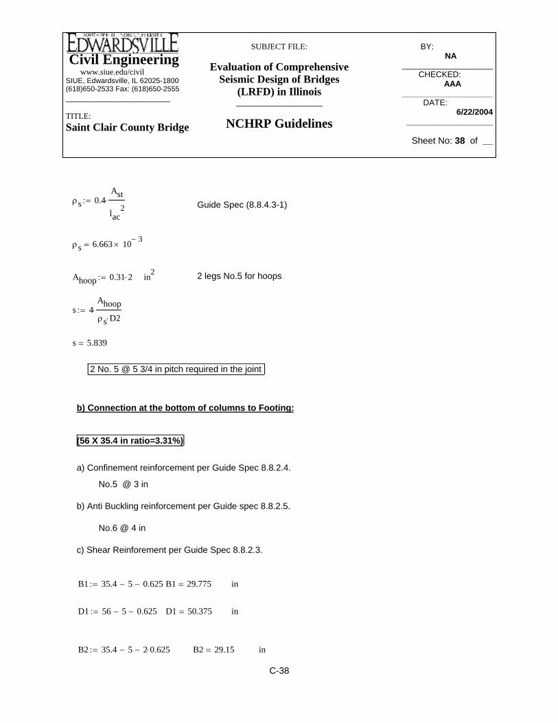
Civil Engineering www.siue.edu/civilSIUE, Edwardsville, IL 62025-1800(618)650-2533 Fax: (618)650-2555_______________________
TITLE:Saint Clair County Bridge
SUBJECT FILE:
Evaluation of Comprehensive Seismic Design of Bridges
(LRFD) in Illinois___________________
NCHRP Guidelines
BY:_____________ NA________
____________________CHECKED: _____
AAA_______ ____________________
DATE:__________ 6/22/2004
___________________
Sheet No: 38 of __
inB2 29.15=B2 35.4 5− 2 0.625⋅−:=
inD1 50.375=D1 56 5− 0.625−:=
inB1 29.775=B1 35.4 5− 0.625−:=
c) Shear Reinforement per Guide Spec 8.8.2.3.
No.6 @ 4 in
b) Anti Buckling reinforcement per Guide spec 8.8.2.5.
No.5 @ 3 in
a) Confinement reinforcement per Guide Spec 8.8.2.4.
(56 X 35.4 in ratio=3.31%)
b) Connection at the bottom of columns to Footing:
2 No. 5 @ 5 3/4 in pitch required in the joint
s 5.839=
s 4Ahoopρs D2⋅⋅:=
2 legs No.5 for hoopsin2Ahoop 0.31 2⋅:=
ρs 6.663 10 3−×=
Guide Spec (8.8.4.3-1)ρs 0.4Ast
lac2
⋅:=
C-38

Civil Engineering www.siue.edu/civilSIUE, Edwardsville, IL 62025-1800(618)650-2533 Fax: (618)650-2555_______________________
TITLE:Saint Clair County Bridge
SUBJECT FILE:
Evaluation of Comprehensive Seismic Design of Bridges
(LRFD) in Illinois___________________
NCHRP Guidelines
BY:_____________ NA________
____________________CHECKED: _____
AAA_______ ____________________
DATE:__________ 6/22/2004
___________________
Sheet No: 39 of __
in2 Cross-Sectional Area of Column core
D 35.4:= in Width of the column framing into the joint
Hc 66.93:= in Height of the Pile cap
tanαDHc
:=
ρ 1.2
B1D1
0.5 ρt⋅ fsu⋅ Ag⋅+
2B1D1⋅ 2 φ⋅ fyh⋅ Ac⋅+
⋅DHc
⎛⎜⎝
⎞⎠
2⋅:= For a rectangular column, minimum ratio
ρ 6.329 10 3−×=
Ash 2 .31⋅:=
sAshρ B2⋅
:= s 3.361= maximum
2 No.5 @ 3 1/4 in
Use No. 5 @ 3 in
inD2 56 5− 2 0.625⋅−:= D2 49.75=
φ 0.90:= Strength Reduction Factor for shear
fyh 60000:= psi Yeild Strength of Ties
fsu 1.5 fyh⋅:= fsu 9 104×= psi
ρt 0.0331:= Longitudinal Steel Content
Ag 56 35.4⋅:= Ag 1.982 103×= in2 Cross-Sectional Area of Columns
Ac B2 D2⋅:= Ac 1.45 103×=
C-39

Civil Engineering www.siue.edu/civilSIUE, Edwardsville, IL 62025-1800(618)650-2533 Fax: (618)650-2555_______________________
TITLE:Saint Clair County Bridge
SUBJECT FILE:
Evaluation of Comprehensive Seismic Design of Bridges
(LRFD) in Illinois___________________
NCHRP Guidelines
BY:_____________ NA________
____________________CHECKED: _____
AAA_______ ____________________
DATE:__________ 6/22/2004
___________________
Sheet No: 40 of __
hc 56:=The column lateral dimention
The effective joint widthbje bb:=
Pile Cap Depthinhb 43.3:=
ksifv 0.239=
Average axial stress in the horizontal directionfvPmax
Amid_depth_jt:=
in2Amid_depth_jt 4.029 103×=
Amid_depth_jt bb Lmid_depth_jt⋅:=
inLmid_depth_jt 102.33=
Explicit Approach for the joint Design [Guide Spec, Article 8.8.4.2]:
Case 1: from the transverse displacement capacity verification with overstrenght:
fh 0:= ksi Average axial stress in the horizontal direction
Pmax 962:= kip
At mid-depth of joint
Mp 5058:= kip ft−
bb 39.37:= in Width of the pile Cap
Hc 66.93:= in Hight of the joint
Lmid_depth_jt D Hc+:=
C-40

Civil Engineering www.siue.edu/civilSIUE, Edwardsville, IL 62025-1800(618)650-2533 Fax: (618)650-2555_______________________
TITLE:Saint Clair County Bridge
SUBJECT FILE:
Evaluation of Comprehensive Seismic Design of Bridges
(LRFD) in Illinois___________________
NCHRP Guidelines
BY:_____________ NA________
____________________CHECKED: _____
AAA_______ ____________________
DATE:__________ 6/22/2004
___________________
Sheet No: 41 of __
Principle compression stress (8.8.4.2-2).pc
fh fv+( )2
fh fv−
2
⎛⎜⎝
⎞⎠
2
vhv2
++:=
pc 0.766= ksi
pc_max 0.25 fc⋅:= Maximum Compression stress [Guide spec, Article 8.8.4.2.3]
pc_max 0.87= ksi > pc OK
Case 2:Pmin 359:= kip
kip ft−Mp 3778:=
Obviously it will produce amaller principle srtesses than Case1.
vhvMp 12⋅
hb hc⋅ bje⋅:= The average shear stress within the plane of the connection.
vhv 0.636= ksi
fc 3.48:= ksi Compressive Strength of Concrete
Principle tention stress (8.8.4.2-1).pt
fh fv+( )2
fh fv−
2
⎛⎜⎝
⎞⎠
2
vhv2
+−:=
pt 0.528−= ksi
Maximum tention stress Pt_max 3.5
fc1000
⋅:=
ptPt_max 0.206= ksi <
Therefore must use Guide spec 8.8.4.3.
C-41
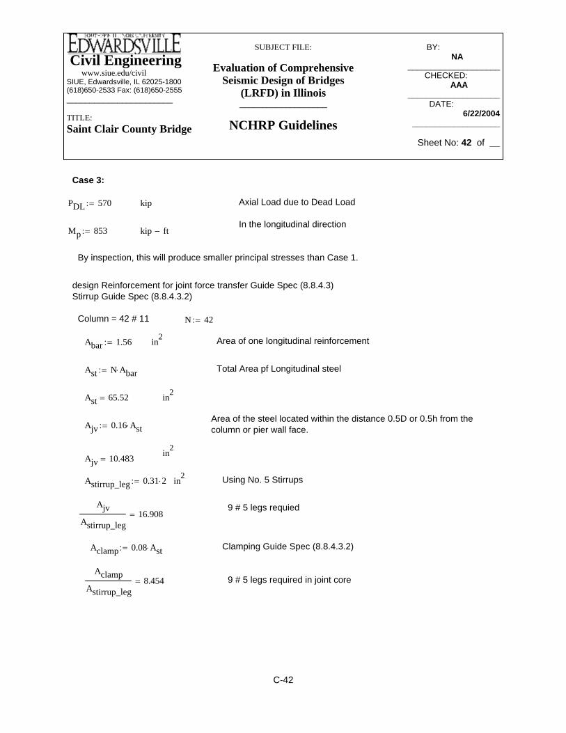
Civil Engineering www.siue.edu/civilSIUE, Edwardsville, IL 62025-1800(618)650-2533 Fax: (618)650-2555_______________________
TITLE:Saint Clair County Bridge
SUBJECT FILE:
Evaluation of Comprehensive Seismic Design of Bridges
(LRFD) in Illinois___________________
NCHRP Guidelines
BY:_____________ NA________
____________________CHECKED: _____
AAA_______ ____________________
DATE:__________ 6/22/2004
___________________
Sheet No: 42 of __
9 # 5 legs required in joint coreAclamp
Astirrup_leg8.454=
Clamping Guide Spec (8.8.4.3.2)Aclamp 0.08 Ast⋅:=
AjvAstirrup_leg
16.908=9 # 5 legs requied
Using No. 5 Stirrupsin2Astirrup_leg 0.31 2⋅:=
Ajv 10.483=in2
Ajv 0.16 Ast⋅:=Area of the steel located within the distance 0.5D or 0.5h from the column or pier wall face.
in2Ast 65.52=
Total Area pf Longitudinal steelAst N Abar⋅:=
Area of one longitudinal reinforcementin2Abar 1.56:=
N 42:=Column = 42 # 11
design Reinforcement for joint force transfer Guide Spec (8.8.4.3)Stirrup Guide Spec (8.8.4.3.2)
By inspection, this will produce smaller principal stresses than Case 1.
kip ft−Mp 853:=In the longitudinal direction
Axial Load due to Dead LoadkipPDL 570:=
Case 3:
C-42

Civil Engineering www.siue.edu/civilSIUE, Edwardsville, IL 62025-1800(618)650-2533 Fax: (618)650-2555_______________________
TITLE:Saint Clair County Bridge
SUBJECT FILE:
Evaluation of Comprehensive Seismic Design of Bridges
(LRFD) in Illinois___________________
NCHRP Guidelines
BY:_____________ NA________
____________________CHECKED: _____
AAA_______ ____________________
DATE:__________ 6/22/2004
___________________
Sheet No: 43 of __
ksi
fc 3.48:= ksi
Abar 1.56:= in2 Cross-Section Area of bar #11
lac 1.25 Abar⋅fy
fc⋅:= Development length of # 11 per AASHTO LRFD 5.11.2.1
lac 62.719= in
ρs 0.4Ast
lac2
⋅:= Guide Spec (8.8.4.3-1)
ρs 6.663 10 3−×=
Ahoop 0.31 2⋅:= in2 2 legs No.5 for hoops
s 4Ahoopρs D2⋅⋅:=
s 7.482= 2 No. 5 @ 7 1/4 in pitch required in the joint
Horizontal reinforcement Guide Spec (8.8.4.3.2)
Ah 0.08 Ast⋅:=fy 60:= ksi
Abar 1.0:= in2Using No.9 bars,
fc 3.48:= ksi
db 1.128:= in for No. 9AhAbar
5.242= 6 # 9 in footing
Ld 0.4 fy⋅ db⋅:=Ld 1.25 Abar⋅fy
fc⋅:=
No more thanLd 27.072=
Ld 40.204=
Hoop Reinforcement Guide Spec (8.8.4.3.4)
fy 60:=
C-43

Civil Engineering www.siue.edu/civilSIUE, Edwardsville, IL 62025-1800(618)650-2533 Fax: (618)650-2555_______________________
TITLE:Saint Clair County Bridge
SUBJECT FILE:
Evaluation of Comprehensive Seismic Design of Bridges
(LRFD) in Illinois___________________
NCHRP Guidelines
BY:_____________ NA________
____________________CHECKED: _____
AAA_______ ____________________
DATE:__________ 6/22/2004
___________________
Sheet No: 44 of __
Thickness of pile cap (ft)T 4:=
Length of wall (ft)L 64.08:=
Width of Wall (ft)W 3.28:=
Dimensions of pier
Monent in Transvers directionkipV 2987:=
Monent in Longitudinal directionkip ft−M2 29260:=
Monent in Transvers directionkip ft−M1 25116:=
Moments and Forces acting on piles:
psiFy 60000:=
psiFc 3480:=
Footing design procedure for St. Clair County bridge
C-44

Civil Engineering www.siue.edu/civilSIUE, Edwardsville, IL 62025-1800(618)650-2533 Fax: (618)650-2555_______________________
TITLE:Saint Clair County Bridge
SUBJECT FILE:
Evaluation of Comprehensive Seismic Design of Bridges
(LRFD) in Illinois___________________
NCHRP Guidelines
BY:_____________ NA________
____________________CHECKED: _____
AAA_______ ____________________
DATE:__________ 6/22/2004
___________________
Sheet No: 45 of __
x4 43.75:= x7 25:= x10 6.25:= x13 12.5−:= x16 31.25−:= x19 50−:=
y1 12.5:= y4 12.5:= y7 12.5:= y10 12.5:= y13 12.5:= y16 12.5:= y19 12.5:=
x2 56.25:= x5 37.5:= x8 18.75:= x11 0:= x14 18.75−:= x17 37.5−:= x20 56.25−:=y2 12.5:= y5 12.5:= y8 12.5:= y11 12.5:= y14 12.5:= y17 12.5:= y20 12.5:=
s 6.25:= ft Distance between piles
m1 5:= Number of rows
n1 21:= Number of piles in the rows
Σd1s2
12n1⋅ n12 1−( )⋅ m1⋅:= Sum of the squares of the distances to each pile from the center
or gravity of piles
Σd1 1.504 105×= pile ft2
m2 21:= Number of rows
n2 5:= Number of piles in the rows
Σd2s2
12n2⋅ n22 1−( )⋅ m2⋅:=
Σd2 8.203 103×=
pileft2
M1 25116:= kip ft−
kip ft−M2 29260:=
kipV 2987:=
Piles Coordinates:
1st row
x1 62.5:=
C-45

Civil Engineering www.siue.edu/civilSIUE, Edwardsville, IL 62025-1800(618)650-2533 Fax: (618)650-2555_______________________
TITLE:Saint Clair County Bridge
SUBJECT FILE:
Evaluation of Comprehensive Seismic Design of Bridges
(LRFD) in Illinois___________________
NCHRP Guidelines
BY:_____________ NA________
____________________CHECKED: _____
AAA_______ ____________________
DATE:__________ 6/22/2004
___________________
Sheet No: 46 of __
y54 0:=y51 0:=y48 0:=y45 0:=
x63 62.5−:=x60 43.75−:=x57 25−:=x54 6.25−:=x51 12.5:=x48 31.25:=x45 50:=
y62 0:=y59 0:=y56 0:=y53 0:=y50 0:=y47 0:=y44 0:=
x62 56.25−:=x59 37.5−:=x56 18.75−:=x53 0:=x50 18.75:=x47 37.5:=x44 56.25:=
y61 0:=y58 0:=y55 0:=y52 0:=y49 0:=y46 0:=y43 0:=
y83 6.25−:=y80 6.25−:=y77 6.25−:=y74 6.25−:=y71 6.25−:=y68 6.25−:=y65 6.25−:=
x83 56.25−:=x80 37.5−:=x77 18.75−:=x74 0:=x71 18.75:=x68 37.5:=x65 56.25:=
y82 6.25−:=y79 6.25−:=y76 6.25−:=y73 6.25−:=y70 6.25−:=y67 6.25−:=y64 6.25−:=
x82 50−:=x79 31.25−:=x76 12.5−:=x73 6.25:=x70 25:=x67 43.75:=x64 62.5:=
4th row
y63 0:=y60 0:=y57 0:=
x29 18.75:=x26 37.5:=x23 56.25:=
y40 6.25:=y37 6.25:=y34 6.25:=y31 6.25:=y28 6.25:=y25 6.25:=y22 6.25:=
x40 50−:=x37 31.25−:=x34 12.5−:=x31 6.25:=x28 25:=x25 43.75:=x22 62.5:=
2nd row
y21 12.5:=y18 12.5:=y15 12.5:=y12 12.5:=y9 12.5:=y6 12.5:=y3 12.5:=
x21 62.5−:=x18 43.75−:=x15 25−:=x12 6.25−:=x9 12.5:=x6 31.25:=x3 50:=
x61 50−:=x58 31.25−:=x55 12.5−:=x52 6.25:=x49 25:=x46 43.75:=x43 62.5:=
3rd row
y42 6.25:=y39 6.25:=y36 6.25:=y33 6.25:=y30 6.25:=y27 6.25:=y24 6.25:=
x42 62.5−:=
x32 0:= x35 18.75−:= x38 37.5−:= x41 56.25−:=y23 6.25:= y26 6.25:= y29 6.25:= y32 6.25:= y35 6.25:= y38 6.25:= y41 6.25:=
x24 50:= x27 31.25:= x30 12.5:= x33 6.25−:= x36 25−:= x39 43.75−:=
C-46
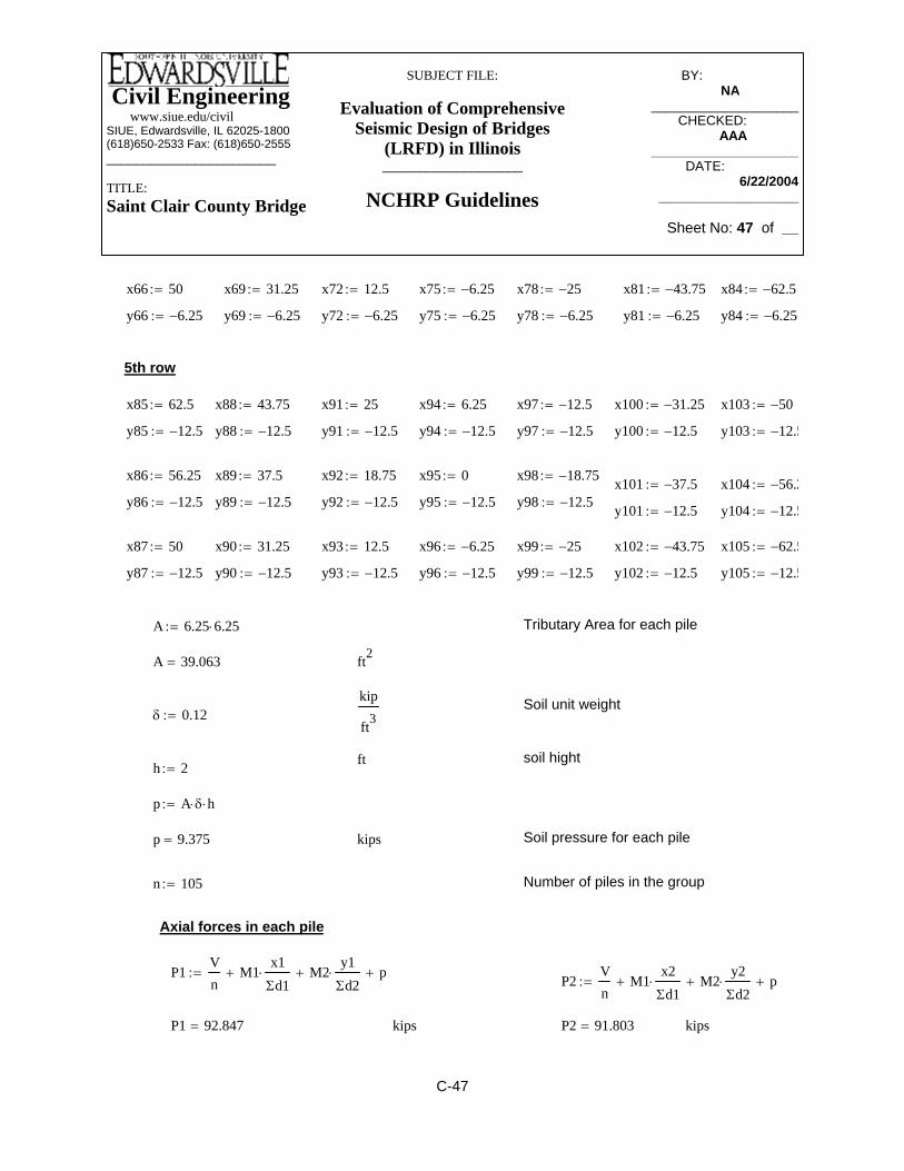
Civil Engineering www.siue.edu/civilSIUE, Edwardsville, IL 62025-1800(618)650-2533 Fax: (618)650-2555_______________________
TITLE:Saint Clair County Bridge
SUBJECT FILE:
Evaluation of Comprehensive Seismic Design of Bridges
(LRFD) in Illinois___________________
NCHRP Guidelines
BY:_____________ NA________
____________________CHECKED: _____
AAA_______ ____________________
DATE:__________ 6/22/2004
___________________
Sheet No: 47 of __
A 39.063=
Tributary Area for each pileA 6.25 6.25⋅:=
y105 12.5−:=y102 12.5−:=y99 12.5−:=y96 12.5−:=y93 12.5−:=y90 12.5−:=y87 12.5−:=
x105 62.5−:=x102 43.75−:=x99 25−:=x96 6.25−:=x93 12.5:=x90 31.25:=x87 50:=
y104 12.5−:=y101 12.5−:=y98 12.5−:=
kipsP2 91.803=kipsP1 92.847=
P2Vn
M1x2Σd1⋅+ M2
y2Σd2⋅+ p+:=
P1Vn
M1x1Σd1⋅+ M2
y1Σd2⋅+ p+:=
Axial forces in each pile
Number of piles in the groupn 105:=
Soil pressure for each pilekipsp 9.375=
p A δ⋅ h⋅:=
h 2:=soil hightft
δ 0.12:=Soil unit weightkip
ft3
ft2
x97 12.5−:=x94 6.25:=x91 25:=x88 43.75:=x85 62.5:=
5th row
y84 6.25−:=y81 6.25−:=y78 6.25−:=y75 6.25−:=y72 6.25−:=y69 6.25−:=y66 6.25−:=
x84 62.5−:=x81 43.75−:=x78 25−:=x75 6.25−:=x72 12.5:=x69 31.25:=x66 50:=
y95 12.5−:=y92 12.5−:=y89 12.5−:=y86 12.5−:=x104 56.2−:=x101 37.5−:=
x98 18.75−:=x95 0:=x92 18.75:=x89 37.5:=x86 56.25:=
y103 12.5−:=y100 12.5−:=y97 12.5−:=y94 12.5−:=y91 12.5−:=y88 12.5−:=y85 12.5−:=
x103 50−:=x100 31.25−:=
C-47

Civil Engineering www.siue.edu/civilSIUE, Edwardsville, IL 62025-1800(618)650-2533 Fax: (618)650-2555_______________________
TITLE:Saint Clair County Bridge
SUBJECT FILE:
Evaluation of Comprehensive Seismic Design of Bridges
(LRFD) in Illinois___________________
NCHRP Guidelines
BY:_____________ NA________
____________________CHECKED: _____
AAA_______ ____________________
DATE:__________ 6/22/2004
___________________
Sheet No: 48 of __
kips P10 83.453=
P11Vn
M1x11Σd1⋅+ M2
y11Σd2⋅+ p+:= P12
Vn
M1x12Σd1⋅+ M2
y12Σd2⋅+ p+:=
P11 82.409= kips P12 81.366=
P13Vn
M1x13Σd1⋅+ M2
y13Σd2⋅+ p+:= P14
Vn
M1x14Σd1⋅+ M2
y14Σd2⋅+ p+:=
kips P14 79.278=P13 80.322=
P15Vn
M1x15Σd1⋅+ M2
y15Σd2⋅+ p+:= P16
Vn
M1x16Σd1⋅+ M2
y16Σd2⋅+ p+:=
kips P16 77.19=P15 78.234=
P3Vn
M1x3Σd1⋅+ M2
y3Σd2⋅+ p+:= P4
Vn
M1x4Σd1⋅+ M2
y4Σd2⋅+ p+:=
P3 90.76= kips P4 89.716=
P5Vn
M1x5Σd1⋅+ M2
y5Σd2⋅+ p+:= P6
Vn
M1x6Σd1⋅+ M2
y6Σd2⋅+ p+:=
P5 88.672= kips P6 87.628=
P7Vn
M1x7Σd1⋅+ M2
y7Σd2⋅+ p+:= P8
Vn
M1x8Σd1⋅+ M2
y8Σd2⋅+ p+:=
P7 86.584= kips P8 85.541=
P9Vn
M1x9Σd1⋅+ M2
y9Σd2⋅+ p+:= P10
Vn
M1x10Σd1⋅+ M2
y10Σd2⋅+ p+:=
P9 84.497=
C-48

Civil Engineering www.siue.edu/civilSIUE, Edwardsville, IL 62025-1800(618)650-2533 Fax: (618)650-2555_______________________
TITLE:Saint Clair County Bridge
SUBJECT FILE:
Evaluation of Comprehensive Seismic Design of Bridges
(LRFD) in Illinois___________________
NCHRP Guidelines
BY:_____________ NA________
____________________CHECKED: _____
AAA_______ ____________________
DATE:__________ 6/22/2004
___________________
Sheet No: 49 of __
P27 65.335=P28 64.291=kips
P28Vn
M1x28Σd1⋅+ M2
y28Σd2⋅+ p+:=P27
Vn
M1x27Σd1⋅+ M2
y27Σd2⋅+ p+:=
P26 66.379=kipsP25 67.422=
P26Vn
M1x26Σd1⋅+ M2
y26Σd2⋅+ p+:=P25
Vn
M1x25Σd1⋅+ M2
y25Σd2⋅+ p+:=
P23 69.51=P24 68.466=kips
P24Vn
M1x24Σd1⋅+ M2
y24Σd2⋅+ p+:=P23
Vn
M1x23Σd1⋅+ M2
y23Σd2⋅+ p+:=
P21 71.971=P22 70.554=kips
P22Vn
M1x22Σd1⋅+ M2
y22Σd2⋅+ p+:=P21
Vn
M1x21Σd1⋅+ M2
y21Σd2⋅+ p+:=
P19 74.059=P20 73.015=kips
P20Vn
M1x20Σd1⋅+ M2
y20Σd2⋅+ p+:=P19
Vn
M1x19Σd1⋅+ M2
y19Σd2⋅+ p+:=
P17 76.147=P18 75.103=kips
P18Vn
M1x18Σd1⋅+ M2
y18Σd2⋅+ p+:=P17
Vn
M1x17Σd1⋅+ M2
y17Σd2⋅+ p+:=
C-49

Civil Engineering www.siue.edu/civilSIUE, Edwardsville, IL 62025-1800(618)650-2533 Fax: (618)650-2555_______________________
TITLE:Saint Clair County Bridge
SUBJECT FILE:
Evaluation of Comprehensive Seismic Design of Bridges
(LRFD) in Illinois___________________
NCHRP Guidelines
BY:_____________ NA________
____________________CHECKED: _____
AAA_______ ____________________
DATE:__________ 6/22/2004
___________________
Sheet No: 50 of __
P40 51.766=kipsP39 52.809=
P40Vn
M1x40Σd1⋅+ M2
y40Σd2⋅+ p+:=P39
Vn
M1x39Σd1⋅+ M2
y39Σd2⋅+ p+:=
P38 53.853=kipsP37 54.897=
P38Vn
M1x38Σd1⋅+ M2
y38Σd2⋅+ p+:=P37
Vn
M1x37Σd1⋅+ M2
y37Σd2⋅+ p+:=
P36 55.941=kipsP35 56.985=
P35Vn
M1x35Σd1⋅+ M2
y35Σd2⋅+ p+:=
P36Vn
M1x36Σd1⋅+ M2
y36Σd2⋅+ p+:=
P34 58.028=kipsP33 59.072=
P33Vn
M1x33Σd1⋅+ M2
y33Σd2⋅+ p+:=
P34Vn
M1x34Σd1⋅+ M2
y34Σd2⋅+ p+:=
P31 61.16=P32 60.116=kips
P32Vn
M1x32Σd1⋅+ M2
y32Σd2⋅+ p+:=P31
Vn
M1x31Σd1⋅+ M2
y31Σd2⋅+ p+:=
P29 63.247=P30 62.204=kips
P30Vn
M1x30Σd1⋅+ M2
y30Σd2⋅+ p+:=P29
Vn
M1x29Σd1⋅+ M2
y29Σd2⋅+ p+:=
C-50

Civil Engineering www.siue.edu/civilSIUE, Edwardsville, IL 62025-1800(618)650-2533 Fax: (618)650-2555_______________________
TITLE:Saint Clair County Bridge
SUBJECT FILE:
Evaluation of Comprehensive Seismic Design of Bridges
(LRFD) in Illinois___________________
NCHRP Guidelines
BY:_____________ NA________
____________________CHECKED: _____
AAA_______ ____________________
DATE:__________ 6/22/2004
___________________
Sheet No: 51 of __
P48Vn
M1x48Σd1⋅+ M2
y48Σd2⋅+ p+:=
P47 44.085= kips kipsP48 43.042=
P49Vn
M1x49Σd1⋅+ M2
y49Σd2⋅+ p+:= P50
Vn
M1x50Σd1⋅+ M2
y50Σd2⋅+ p+:=
P49 41.998= kips kipsP50 40.954=
P51Vn
M1x51Σd1⋅+ M2
y51Σd2⋅+ p+:= P52
Vn
M1x52Σd1⋅+ M2
y52Σd2⋅+ p+:=
P51 39.91= kips kipsP52 38.866=
P53Vn
M1x53Σd1⋅+ M2
y53Σd2⋅+ p+:= P54
Vn
M1x54Σd1⋅+ M2
y54Σd2⋅+ p+:=
P41Vn
M1x41Σd1⋅+ M2
y41Σd2⋅+ p+:= P42
Vn
M1x42Σd1⋅+ M2
y42Σd2⋅+ p+:=
P41 50.722= kips kipsP42 49.678=
P43Vn
M1x43Σd1⋅+ M2
y43Σd2⋅+ p+:= P44
Vn
M1x44Σd1⋅+ M2
y44Σd2⋅+ p+:=
P43 48.26= kips kipsP44 47.217=
P45Vn
M1x45Σd1⋅+ M2
y45Σd2⋅+ p+:= P46
Vn
M1x46Σd1⋅+ M2
y46Σd2⋅+ p+:=
P45 46.173= kips kipsP46 45.129=
P47Vn
M1x47Σd1⋅+ M2
y47Σd2⋅+ p+:=
C-51

Civil Engineering www.siue.edu/civilSIUE, Edwardsville, IL 62025-1800(618)650-2533 Fax: (618)650-2555_______________________
TITLE:Saint Clair County Bridge
SUBJECT FILE:
Evaluation of Comprehensive Seismic Design of Bridges
(LRFD) in Illinois___________________
NCHRP Guidelines
BY:_____________ NA________
____________________CHECKED: _____
AAA_______ ____________________
DATE:__________ 6/22/2004
___________________
Sheet No: 52 of __
P60 30.516= kips
P61Vn
M1x61Σd1⋅+ M2
y61Σd2⋅+ p+:= P62
Vn
M1x62Σd1⋅+ M2
y62Σd2⋅+ p+:=
P61 29.472= kips kipsP62 28.429=
P63Vn
M1x63Σd1⋅+ M2
y63Σd2⋅+ p+:= P64
Vn
M1x64Σd1⋅+ M2
y64Σd2⋅+ p+:=
P63 27.385= kipsP64 25.967= kips
P65Vn
M1x65Σd1⋅+ M2
y65Σd2⋅+ p+:= P66
Vn
M1x66Σd1⋅+ M2
y66Σd2⋅+ p+:=
kipsP65 24.923= P66 23.88= kips
P53 37.823= kipsP54 36.779= kips
P55Vn
M1x55Σd1⋅+ M2
y55Σd2⋅+ p+:= P56
Vn
M1x56Σd1⋅+ M2
y56Σd2⋅+ p+:=
kipsP55 35.735= P56 34.691= kips
P57Vn
M1x57Σd1⋅+ M2
y57Σd2⋅+ p+:= P58
Vn
M1x58Σd1⋅+ M2
y58Σd2⋅+ p+:=
kipsP57 33.647= P58 32.604= kips
P59Vn
M1x59Σd1⋅+ M2
y59Σd2⋅+ p+:= P60
Vn
M1x60Σd1⋅+ M2
y60Σd2⋅+ p+:=
P59 31.56= kips
C-52

Civil Engineering www.siue.edu/civilSIUE, Edwardsville, IL 62025-1800(618)650-2533 Fax: (618)650-2555_______________________
TITLE:Saint Clair County Bridge
SUBJECT FILE:
Evaluation of Comprehensive Seismic Design of Bridges
(LRFD) in Illinois___________________
NCHRP Guidelines
BY:_____________ NA________
____________________CHECKED: _____
AAA_______ ____________________
DATE:__________ 6/22/2004
___________________
Sheet No: 53 of __
P73Vn
M1x73Σd1⋅+ M2
y73Σd2⋅+ p+:= P74
Vn
M1x74Σd1⋅+ M2
y74Σd2⋅+ p+:=
P73 16.573= kipsP74 15.529= kips
P75Vn
M1x75Σd1⋅+ M2
y75Σd2⋅+ p+:= P76
Vn
M1x76Σd1⋅+ M2
y76Σd2⋅+ p+:=
kipsP75 14.486= P76 13.442= kips
P77Vn
M1x77Σd1⋅+ M2
y77Σd2⋅+ p+:= P78
Vn
M1x78Σd1⋅+ M2
y78Σd2⋅+ p+:=
kipsP77 12.398= P78 11.354= kips
P67Vn
M1x67Σd1⋅+ M2
y67Σd2⋅+ p+:= P68
Vn
M1x68Σd1⋅+ M2
y68Σd2⋅+ p+:=
kipsP67 22.836= P68 21.792= kips
P69Vn
M1x69Σd1⋅+ M2
y69Σd2⋅+ p+:= P70
Vn
M1x70Σd1⋅+ M2
y70Σd2⋅+ p+:=
P69 20.748= kipsP70 19.704= kips
P71Vn
M1x71Σd1⋅+ M2
y71Σd2⋅+ p+:= P72
Vn
M1x72Σd1⋅+ M2
y72Σd2⋅+ p+:=
P71 18.661= kips kipsP72 17.617=
C-53

Civil Engineering www.siue.edu/civilSIUE, Edwardsville, IL 62025-1800(618)650-2533 Fax: (618)650-2555_______________________
TITLE:Saint Clair County Bridge
SUBJECT FILE:
Evaluation of Comprehensive Seismic Design of Bridges
(LRFD) in Illinois___________________
NCHRP Guidelines
BY:_____________ NA________
____________________CHECKED: _____
AAA_______ ____________________
DATE:__________ 6/22/2004
___________________
Sheet No: 54 of __
P85Vn
M1x85Σd1⋅+ M2
y85Σd2⋅+ p+:= P86
Vn
M1x86Σd1⋅+ M2
y86Σd2⋅+ p+:=
kipsP85 3.674= P86 2.63= kips
P87Vn
M1x87Σd1⋅+ M2
y87Σd2⋅+ p+:= P88
Vn
M1x88Σd1⋅+ M2
y88Σd2⋅+ p+:=
kipsP87 1.586= P88 0.542= kips
P89Vn
M1x89Σd1⋅+ M2
y89Σd2⋅+ p+:= P90
Vn
M1x90Σd1⋅+ M2
y90Σd2⋅+ p+:=
P89 0.501−= kips P90 1.545−= kips
P79Vn
M1x79Σd1⋅+ M2
y79Σd2⋅+ p+:= P80
Vn
M1x80Σd1⋅+ M2
y80Σd2⋅+ p+:=
P79 10.31= kipsP80 9.267= kips
P81Vn
M1x81Σd1⋅+ M2
y81Σd2⋅+ p+:= P82
Vn
M1x82Σd1⋅+ M2
y82Σd2⋅+ p+:=
P81 8.223= kips kipsP82 7.179=
P83Vn
M1x83Σd1⋅+ M2
y83Σd2⋅+ p+:= P84
Vn
M1x84Σd1⋅+ M2
y84Σd2⋅+ p+:=
P83 6.135= kipsP84 5.091= kips
C-54

Civil Engineering www.siue.edu/civilSIUE, Edwardsville, IL 62025-1800(618)650-2533 Fax: (618)650-2555_______________________
TITLE:Saint Clair County Bridge
SUBJECT FILE:
Evaluation of Comprehensive Seismic Design of Bridges
(LRFD) in Illinois___________________
NCHRP Guidelines
BY:_____________ NA________
____________________CHECKED: _____
AAA_______ ____________________
DATE:__________ 6/22/2004
___________________
Sheet No: 55 of __
P97Vn
M1x97Σd1⋅+ M2
y97Σd2⋅+ p+:= P98
Vn
M1x98Σd1⋅+ M2
y98Σd2⋅+ p+:=
P97 8.852−= kips P98 9.895−= kips
P99Vn
M1x99Σd1⋅+ M2
y99Σd2⋅+ p+:= P100
Vn
M1x100Σd1
⋅+ M2y100Σd2
⋅+ p+:=
P99 10.939−= kips P100 11.983−= kips
P101Vn
M1x101Σd1
⋅+ M2y101Σd2
⋅+ p+:= P102Vn
M1x102Σd1
⋅+ M2y102Σd2
⋅+ p+:=
P101 13.027−= kips P102 14.071−= kips
P91Vn
M1x91Σd1⋅+ M2
y91Σd2⋅+ p+:= P92
Vn
M1x92Σd1⋅+ M2
y92Σd2⋅+ p+:=
P91 2.589−= kips P92 3.633−= kips
P93Vn
M1x93Σd1⋅+ M2
y93Σd2⋅+ p+:= P94
Vn
M1x94Σd1⋅+ M2
y94Σd2⋅+ p+:=
P93 4.676−= kips P94 5.72−= kips
P95Vn
M1x95Σd1⋅+ M2
y95Σd2⋅+ p+:= P96
Vn
M1x96Σd1⋅+ M2
y96Σd2⋅+ p+:=
P95 6.764−= kips P96 7.808−= kips
C-55

Civil Engineering www.siue.edu/civilSIUE, Edwardsville, IL 62025-1800(618)650-2533 Fax: (618)650-2555_______________________
TITLE:Saint Clair County Bridge
SUBJECT FILE:
Evaluation of Comprehensive Seismic Design of Bridges
(LRFD) in Illinois___________________
NCHRP Guidelines
BY:_____________ NA________
____________________CHECKED: _____
AAA_______ ____________________
DATE:__________ 6/22/2004
___________________
Sheet No: 56 of __
Shear strength Vc 4 Fc⋅ b⋅d
1000⋅:=
Perimeter acting in punching shearinb 191.6:=
Concrete slab thickness for 3 ft footingind 45:=
Maximum axial load in pilesKipsVu 92.847=
Vu P1:=
14.9+d
14.9+d
Pile punching shear check:
kipsP105 17.202−=
P105Vn
M1x105Σd1
⋅+ M2y105Σd2
⋅+ p+:=
kipsP104 16.158−=kipsP103 15.114−=
P104Vn
M1x104Σd1
⋅+ M2y104Σd2
⋅+ p+:=P103Vn
M1x103Σd1
⋅+ M2y103Σd2
⋅+ p+:=
C-56

Civil Engineering www.siue.edu/civilSIUE, Edwardsville, IL 62025-1800(618)650-2533 Fax: (618)650-2555_______________________
TITLE:Saint Clair County Bridge
SUBJECT FILE:
Evaluation of Comprehensive Seismic Design of Bridges
(LRFD) in Illinois___________________
NCHRP Guidelines
BY:_____________ NA________
____________________CHECKED: _____
AAA_______ ____________________
DATE:__________ 6/22/2004
___________________
Sheet No: 57 of __
Vc2 4 Fc⋅ b2⋅d
1000⋅:=
Length of pilecapinb2 1575:=
V2 is equale to sum of P43 to P105KipsV2 549.898:=
V1 is equale to sum of P1 to P42KipsV1 2.933 103⋅:=
One way shear Check:
OKVuφ
Vc<Vuφ
109.232=
Strength reduction factorφ 0.85:=
kipsVc 2.034 103×=
C-57

Civil Engineering www.siue.edu/civilSIUE, Edwardsville, IL 62025-1800(618)650-2533 Fax: (618)650-2555_______________________
TITLE:Saint Clair County Bridge
SUBJECT FILE:
Evaluation of Comprehensive Seismic Design of Bridges
(LRFD) in Illinois___________________
NCHRP Guidelines
BY:_____________ NA________
____________________CHECKED: _____
AAA_______ ____________________
DATE:__________ 6/22/2004
___________________
Sheet No: 58 of __
Vc2 1.672 104×=
OKV1φ
3.451 103×=
V1φ
Vc2<
131'-3"
31'-3"
v1 P1 P2+ P3+ P4+ P5+( ):=
v2 P22 P23+ P24+ P25+ P26+( ):=
v3 P43 P44+ P45+ P46+ P47+( ):=
v4 P64 P65+ P66+ P67+ P68+( ):=
v5 P85 P86+ P87+ P88+ P89+( ):=
v v1 v2+ v3+ v4+ v5+:=
v 1.154 103×=
C-58

Civil Engineering www.siue.edu/civilSIUE, Edwardsville, IL 62025-1800(618)650-2533 Fax: (618)650-2555_______________________
TITLE:Saint Clair County Bridge
SUBJECT FILE:
Evaluation of Comprehensive Seismic Design of Bridges
(LRFD) in Illinois___________________
NCHRP Guidelines
BY:_____________ NA________
____________________CHECKED: _____
AAA_______ ____________________
DATE:__________ 6/22/2004
___________________
Sheet No: 59 of __
v0.85
1.358 103×=
b3 375:=
Fc 3480:=
d 36:=
Vc3 4 Fc⋅ b3⋅d
1000⋅:=
Vc3 3.186 103×=
v0.85
Vc3< OK
Two-way shear check:
Vu V1 V2+:=
Vu 3.483 103×=
C-59

Civil Engineering www.siue.edu/civilSIUE, Edwardsville, IL 62025-1800(618)650-2533 Fax: (618)650-2555_______________________
TITLE:Saint Clair County Bridge
SUBJECT FILE:
Evaluation of Comprehensive Seismic Design of Bridges
(LRFD) in Illinois___________________
NCHRP Guidelines
BY:_____________ NA________
____________________CHECKED: _____
AAA_______ ____________________
DATE:__________ 6/22/2004
___________________
Sheet No: 60 of __
b0 801.91 72.37⋅:= Perimter of inside rectangular
b0 5.803 104×= in
Vc 4 Fc⋅ b0⋅ d⋅:=
Vc 4.93 108×=
φ 0.85:= Strength reduction factor
Vuφ
4.098 103×= < Vc ok
Flexure bending design:
C-60

Civil Engineering www.siue.edu/civilSIUE, Edwardsville, IL 62025-1800(618)650-2533 Fax: (618)650-2555_______________________
TITLE:Saint Clair County Bridge
SUBJECT FILE:
Evaluation of Comprehensive Seismic Design of Bridges
(LRFD) in Illinois___________________
NCHRP Guidelines
BY:_____________ NA________
____________________CHECKED: _____
AAA_______ ____________________
DATE:__________ 6/22/2004
___________________
Sheet No: 61 of __
Use 31 # 9 in long direction at the top of footing
In long Direction : 90#9
less than As OKin2Asmin 30.375=
Minimum reinfocementAsmin 0.0018 45⋅ 375⋅:=
in2As 88.727=
Area of steel AsMu
Φ Fy⋅ 0.9⋅ d⋅:=
Strength reduction factorΦ 0.9:=
lb in−Mu 1.552 108×=
Mu M1 M2+ M3+ M4+ M5+:=
M5 P21 P42+ P63+ P84+ P105+( ) 366⋅ 1000⋅:=
M4 P20 P41+ P62+ P83+ P104+( ) 291⋅ 1000⋅:=
M3 P19 P40+ P61+ P82+ P103+( ) 216⋅ 1000⋅:=
M2 P18 P39+ P60+ P81+ P102+( ) 141⋅ 1000⋅:=
M1 P17 P38+ P59+ P80+ P101+( ) 66⋅ 1000⋅:=
SECTION A-A
C-61

Civil Engineering www.siue.edu/civilSIUE, Edwardsville, IL 62025-1800(618)650-2533 Fax: (618)650-2555_______________________
TITLE:Saint Clair County Bridge
SUBJECT FILE:
Evaluation of Comprehensive Seismic Design of Bridges
(LRFD) in Illinois___________________
NCHRP Guidelines
BY:_____________ NA________
____________________CHECKED: _____
AAA_______ ____________________
DATE:__________ 6/22/2004
___________________
Sheet No: 62 of __
Use 103 # 9 in short direction at the top of footing
In short direction: 149 # 9
less than As OKin2Asmin 127.575=
Minimum reinfocementAsmin 127.575=
Asmin 0.0018 45⋅ 1575⋅:=
in2As 148.185=
Area of steel AsMu
Φ Fy⋅ 0.9⋅ d⋅:=
Strength reduction factorΦ 0.9:=
lb in−Mu 2.593 108×=
Mu M1 M2+:=
M2 V2( ) 130⋅ 1000⋅:=
V1 is equal to sumation of P1 to P21
V2 is equal to sumation of P22 to P42
M1 V1( ) 55⋅ 1000⋅:=
V2 1.262 103⋅:=
V1 1.731 103⋅:=
SECTION B-B
C-62

Civil Engineering www.siue.edu/civilSIUE, Edwardsville, IL 62025-1800(618)650-2533 Fax: (618)650-2555_______________________
TITLE:Saint Clair County Bridge
SUBJECT FILE:
Evaluation of Comprehensive Seismic Design of Bridges
(LRFD) in Illinois___________________
NCHRP Guidelines
BY:_____________ NA________
____________________CHECKED: _____
AAA_______ ____________________
DATE:__________ 6/22/2004
___________________
Sheet No: 63 of __
CAP Beam Design:
For Cap-beam design, a simple 2D model under developed. (11 concentrated loads applying on the beam as shown below).
Fig.4. 2D model of Cap-beam
Shear 2 Shear 3 Moment 2 Moment 3 kips kips kip-ft kip-ft
Shear 2 Shear 3 Moment 2 Moment 3 kips kips kip-ft kip-ft
Shear 2 Shear 3 Moment 2 Moment 3 kips kips kip-ft kip-ft
NCHRPForces & Moments-Long(X) EQ
100%Long+40%Trans
Location
NCHRPForces & Moments-Trans(Y) EQ
100%Trans+40%Long
Location
0 0 208
Location
Beam 49
5 8
NCHRPForces & Moments-dead load
5522
Beam 783 6 11 4186
Beam 593
C-63
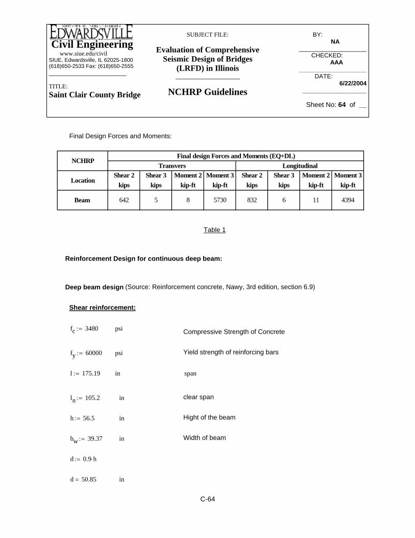
Civil Engineering www.siue.edu/civilSIUE, Edwardsville, IL 62025-1800(618)650-2533 Fax: (618)650-2555_______________________
TITLE:Saint Clair County Bridge
SUBJECT FILE:
Evaluation of Comprehensive Seismic Design of Bridges
(LRFD) in Illinois___________________
NCHRP Guidelines
BY:_____________ NA________
____________________CHECKED: _____
AAA_______ ____________________
DATE:__________ 6/22/2004
___________________
Sheet No: 64 of __
ind 50.85=
d 0.9 h⋅:=
Width of beaminbw 39.37:=
Hight of the beaminh 56.5:=
clear spaninln 105.2:=
spaninl 175.19:=
Yield strength of reinforcing barspsify 60000:=
Compressive Strength of Concretepsifc 3480:=
Shear reinforcement:
Deep beam design (Source: Reinforcement concrete, Nawy, 3rd edition, section 6.9)
Reinforcement Design for continuous deep beam:
Table 1
Shear 2 Shear 3 Moment 2 Moment 3 Shear 2 Shear 3 Moment 2 Moment 3 kips kips kip-ft kip-ft kips kips kip-ft kip-ft
Final design Forces and Moments (EQ+DL)Transvers
Location
Beam 642 5 8 5730
NCHRPLongitudinal
832 6 11 4394
Final Design Forces and Moments:
C-64

Civil Engineering www.siue.edu/civilSIUE, Edwardsville, IL 62025-1800(618)650-2533 Fax: (618)650-2555_______________________
TITLE:Saint Clair County Bridge
SUBJECT FILE:
Evaluation of Comprehensive Seismic Design of Bridges
(LRFD) in Illinois___________________
NCHRP Guidelines
BY:_____________ NA________
____________________CHECKED: _____
AAA_______ ____________________
DATE:__________ 6/22/2004
___________________
Sheet No: 65 of __
ρw 3.552 10 3−×=
Steel Ratio in tension (9 No.8)ρw9 0.79⋅
bw d⋅:=
Use 2.5 > 2.53.5 2.5MuVu d⋅⋅− 3.495=
Mu 3.145 103×=
Mu
Vln12
⎛⎜⎝
⎞⎠
⋅
2
0.15 ln⋅
12
⎛⎜⎝
⎞⎠
⋅
V0.15ln
12
⎛⎜⎝
⎞⎠
2
⋅
2−:=
OK> VukipφVn 8.031 105×=
factored shear force (6-18a)φVn φ 8⋅ fc⋅ bw⋅ d⋅:=
Strength reduction factorφ 0.85:=
kipVu 3.292 104×=
VuV ln⋅
2V
0.15 ln⋅
12⋅−:=
Design shear force from table 1 V 642:=kip
Distance of the critical section (6.17a)in0.15 ln⋅ 15.78=
< 5 , hence treat as a deep beamlnd
2.069=
C-65

Civil Engineering www.siue.edu/civilSIUE, Edwardsville, IL 62025-1800(618)650-2533 Fax: (618)650-2555_______________________
TITLE:Saint Clair County Bridge
SUBJECT FILE:
Evaluation of Comprehensive Seismic Design of Bridges
(LRFD) in Illinois___________________
NCHRP Guidelines
BY:_____________ NA________
____________________CHECKED: _____
AAA_______ ____________________
DATE:__________ 6/22/2004
___________________
Sheet No: 66 of __
Maximum Spacing or 18 ind5
10.17=
Vs 3.868 105×=
VsAvS1
1lnd
+
12⋅
AvhS1
11lnd
−
12⋅+
⎛⎜⎜⎜⎝
⎞⎟
⎠fy⋅ d⋅:=
S1 18:=Try
Avh 2.64=
6 No.6 in horizontal positionAvh 6 0.44⋅:=
4 No. 5Av .31 4⋅:=
Vs 3.803 104×=
VsVuφ
Vc1000
−:=
Assume No.5 bars placed both horizontally and vertically on both faces
Controls Vc 6 fc⋅ bw⋅ d⋅:= 7.086 105×( )=
lbVc 2.421 107×=
Vc 2.5 1.9 fc⋅ 2500 ρw⋅Vu d⋅
Mu⋅+
⎛⎜⎝
⎞
⎠bw⋅ d⋅:=
C-66

Civil Engineering www.siue.edu/civilSIUE, Edwardsville, IL 62025-1800(618)650-2533 Fax: (618)650-2555_______________________
TITLE:Saint Clair County Bridge
SUBJECT FILE:
Evaluation of Comprehensive Seismic Design of Bridges
(LRFD) in Illinois___________________
NCHRP Guidelines
BY:_____________ NA________
____________________CHECKED: _____
AAA_______ ____________________
DATE:__________ 6/22/2004
___________________
Sheet No: 67 of __
in2As 13.445=
Area of tension steelAsMn 12000⋅
fy jd⋅:=
injd 51.988=
Lever armjd 0.2 l 1.5 h⋅+( ):=
MnMuφ
:=
Strength reduction factorφ 0.9:=
kip ft−M 5370:=
Flexural Steel:
okless than Avh=3.52. Avh 0.984=
Minimum reinforcementAvh 0.0025 bw⋅ S⋅:=
okless than Av=0.62 Av 0.591=
Minimum reinforcementAv 0.0015 bw⋅ S⋅:=
ControlsS 10:=
or 18 ind3
16.95=
C-67

Civil Engineering www.siue.edu/civilSIUE, Edwardsville, IL 62025-1800(618)650-2533 Fax: (618)650-2555_______________________
TITLE:Saint Clair County Bridge
SUBJECT FILE:
Evaluation of Comprehensive Seismic Design of Bridges
(LRFD) in Illinois___________________
NCHRP Guidelines
BY:_____________ NA________
____________________CHECKED: _____
AAA_______ ____________________
DATE:__________ 6/22/2004
___________________
Sheet No: 68 of __
OKρmin ρmin>ρmin 6.716 10 3−×=
ρminAs
bw d⋅:=
ρmin 1.74 10 3−×=
ρmin 0.03fcfy⋅:=
1)
AASHTO LRFD SEC.5.7.3.3.2:
Checks:
Use 14 # 9 as flexural reinforcement
in2As 13.445=
OKless than Asin2As_min 6.673=
As_min max As1 As2,( ):=
ControlsAs2 5.905=As1 6.673=
As1200 bw⋅ d⋅
fy:=
As23 fc⋅
fybw⋅ d⋅:=
C-68

Civil Engineering www.siue.edu/civilSIUE, Edwardsville, IL 62025-1800(618)650-2533 Fax: (618)650-2555_______________________
TITLE:Saint Clair County Bridge
SUBJECT FILE:
Evaluation of Comprehensive Seismic Design of Bridges
(LRFD) in Illinois___________________
NCHRP Guidelines
BY:_____________ NA________
____________________CHECKED: _____
AAA_______ ____________________
DATE:__________ 6/22/2004
___________________
Sheet No: 69 of __
2)
Fr 7.5 fc⋅:=
Moment of InertiaIg
bw h3⋅
12:=
yth2
:=
Mcr
FrIgyt⋅
12000:= Cracking Moment
Mcr 772.291=
a Asfy
0.85 fc⋅ bw⋅⋅:=
a 6.927=
Mu φ As⋅ fy⋅ da2
−⎛⎜⎝
⎞⎠
⋅1
12000⋅:=
Mu 2.867 103×=
Mu 1.2 Mcr⋅≥ OK
C-69

Civil Engineering www.siue.edu/civilSIUE, Edwardsville, IL 62025-1800(618)650-2533 Fax: (618)650-2555_______________________
TITLE:Saint Clair County Bridge
SUBJECT FILE:
Evaluation of Comprehensive Seismic Design of Bridges
(LRFD) in Illinois___________________
NCHRP Guidelines
BY:_____________ NA________
____________________CHECKED: _____
AAA_______ ____________________
DATE:__________ 6/22/2004
___________________
Sheet No: 70 of __
12'-4"
3'
5'-7"
3'-2"
76'-8"
5'-10"
4'-6"
131'-3"
Fig.5. bent front view with dimensions
31'-3"
3'
5'-7"
3'-3"
2'-11"4'-9"
Fig.6. bent side view with dimensions
C-70
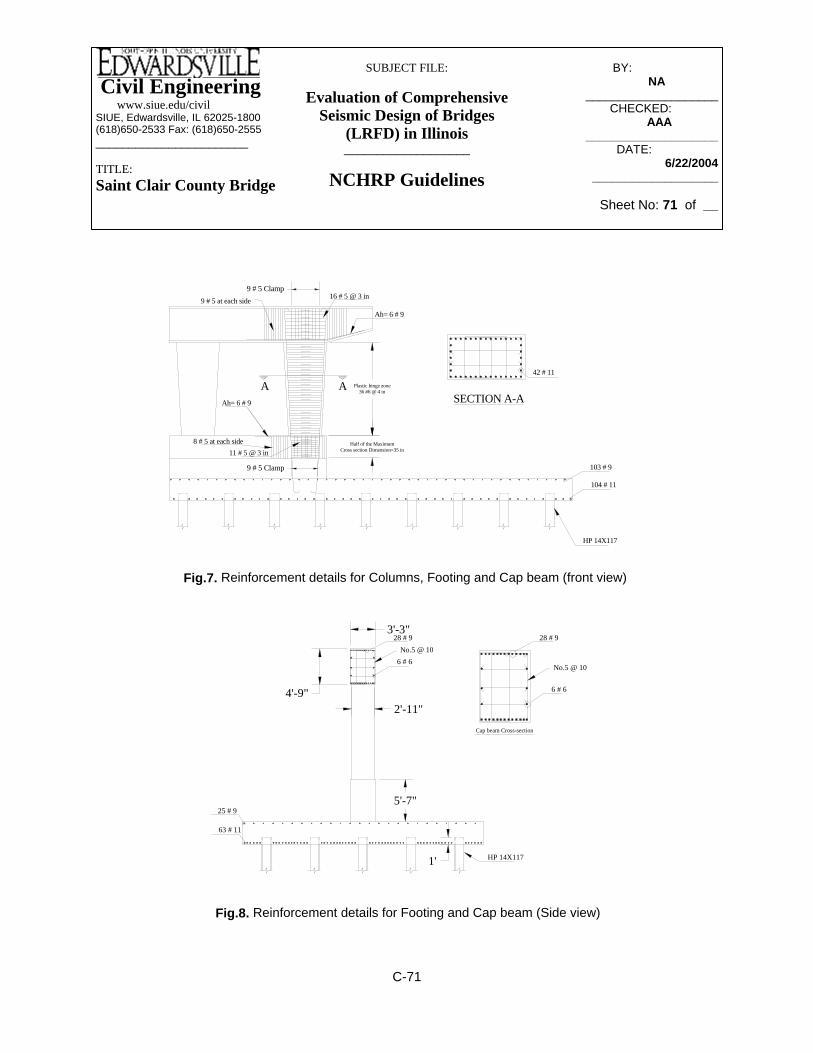
Civil Engineering www.siue.edu/civilSIUE, Edwardsville, IL 62025-1800(618)650-2533 Fax: (618)650-2555_______________________
TITLE:Saint Clair County Bridge
SUBJECT FILE:
Evaluation of Comprehensive Seismic Design of Bridges
(LRFD) in Illinois___________________
NCHRP Guidelines
BY:_____________ NA________
____________________CHECKED: _____
AAA_______ ____________________
DATE:__________ 6/22/2004
___________________
Sheet No: 71 of __
8 # 5 at each side
9 # 5 at each side
Plastic hinge zone36 #6 @ 4 in
Half of the MaximumCross section Dimension=35 in
9 # 5 Clamp
11 # 5 @ 3 in
9 # 5 Clamp
Ah= 6 # 9
A
Ah= 6 # 9
A
16 # 5 @ 3 in
42 # 11
SECTION A-A
104 # 11
103 # 9
HP 14X117
Fig.7. Reinforcement details for Columns, Footing and Cap beam (front view)
5'-7"
4'-9"2'-11"
3'-3"
25 # 9
63 # 11
6 # 6
28 # 9No.5 @ 10
6 # 6
No.5 @ 10
28 # 9
Cap beam Cross-section
HP 14X1171'
Fig.8. Reinforcement details for Footing and Cap beam (Side view)
C-71

Civil Engineering www.siue.edu/civilSIUE, Edwardsville, IL 62025-1800(618)650-2533 Fax: (618)650-2555_______________________
TITLE:
St. Clair County Bridge
SUBJECT FILE:
Evaluation of Comprehensive Seismic Design of Bridges
(LRFD) in Illinois___________________
AASHTOStandard Specifications
BY: _________ G.V.I.______
________________CHECKED: _____
W.N.M._____________________DATE:__________
6/24/2004________________
Sheet No: 1 of 33
Appendix D -- Detailed Computations for Seismic Analysis and Design Check of the St. Clair County Bridge Using AASHTO Specifications
D-1

Civil Engineering www.siue.edu/civilSIUE, Edwardsville, IL 62025-1800(618)650-2533 Fax: (618)650-2555_______________________
TITLE:
St. Clair County Bridge
SUBJECT FILE:
Evaluation of Comprehensive Seismic Design of Bridges
(LRFD) in Illinois___________________
AASHTOStandard Specifications
BY: _________ G.V.I.______
________________CHECKED: _____
W.N.M._____________________DATE:__________
6/24/2004________________
Sheet No: 2 of 33
Table of Contents of Appendix- D Page
SAP 2000 Model
View of SAP 2000 Model………………………………………………………D-3
Enlarged View of Translational and Rotational Springs………………………D-4
Deformed Shapes……………………………………………..…………………D-5
Modal participating Mass Ratios.................................................................D-7
Piles
L-pile Output………………………………………………………………………D-8
Global and Local coordinate systems…………………………………………D-10
Axial Force…………………………………………………………………………D-11
Capacity……………………………………………………………………………D-13
Springs.........................................................................................................D-16
Substructure
Design Forces and Displacements……………………………………………. D-19
PCACOL results......................................................................................... D-21
Section Properties of Superstructure
Pertinent Information about Materials used, etc…………..…………………D-24
Moment of inertia for superstructure...........................................................D-25
Torsional properties....................................................................................D-26
Cross sectional Area.................................................................................. D-26
Loads..........................................................................................................D-27
Columns………………………………………………….……………………… D-28
Cap beam………………………………………………….………………………D-29
Earthquake Data………….………………………………………………………D-30
Design Checks
Moment-Columns……………………………………………………………… D-31
Moment-Crashwall……………………………………………………………… D-31
Shear-Columns………………………………………………………………… D-31
Shear-Crashwall…………………………………………………………….. D-32
Slenderness Effects……………………………………………………………. D-32
D-2
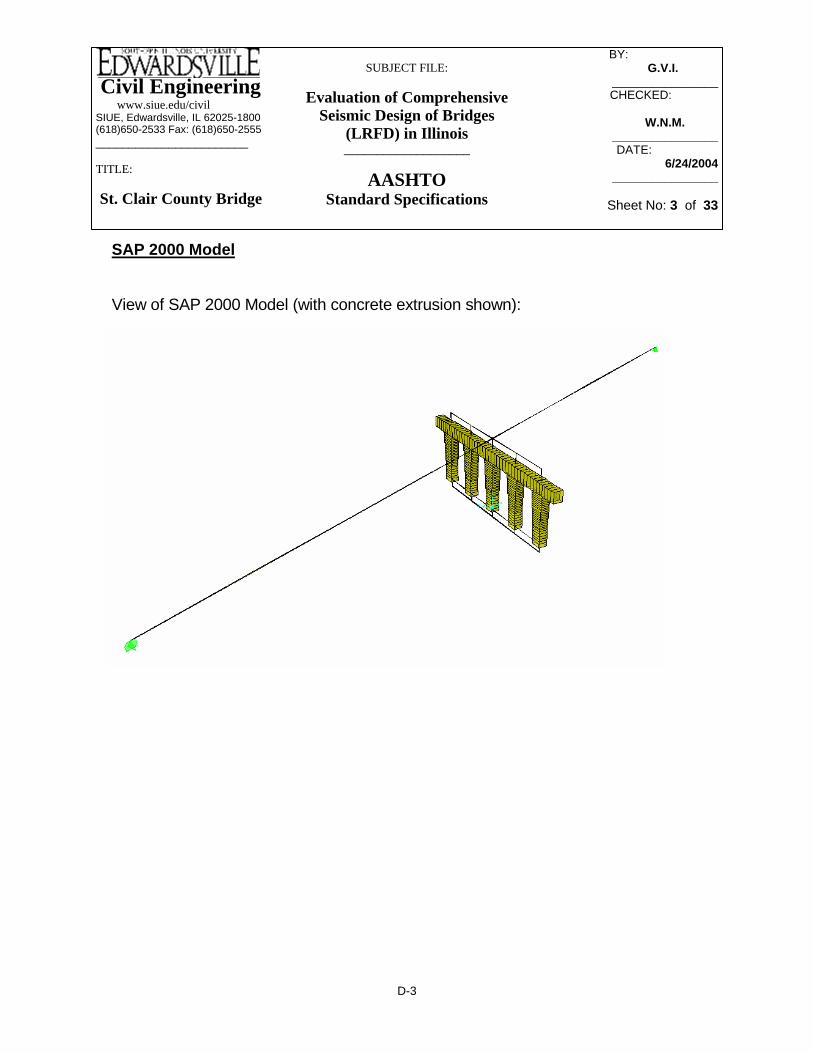
Civil Engineering www.siue.edu/civilSIUE, Edwardsville, IL 62025-1800(618)650-2533 Fax: (618)650-2555_______________________
TITLE:
St. Clair County Bridge
SUBJECT FILE:
Evaluation of Comprehensive Seismic Design of Bridges
(LRFD) in Illinois___________________
AASHTOStandard Specifications
BY: _________ G.V.I.______
________________CHECKED: _____
W.N.M._____________________DATE:__________
6/24/2004________________
Sheet No: 3 of 33
SAP 2000 Model
View of SAP 2000 Model (with concrete extrusion shown):
D-3

Civil Engineering www.siue.edu/civilSIUE, Edwardsville, IL 62025-1800(618)650-2533 Fax: (618)650-2555_______________________
TITLE:
St. Clair County Bridge
SUBJECT FILE:
Evaluation of Comprehensive Seismic Design of Bridges
(LRFD) in Illinois___________________
AASHTOStandard Specifications
BY: _________ G.V.I.______
________________CHECKED: _____
W.N.M._____________________DATE:__________
6/24/2004________________
Sheet No: 4 of 33
Enlarged View of Translational and Rotational Springs:
D-4
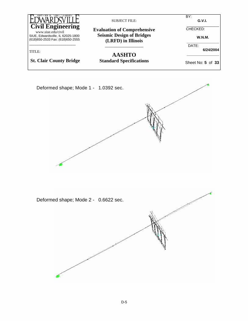
Civil Engineering www.siue.edu/civilSIUE, Edwardsville, IL 62025-1800(618)650-2533 Fax: (618)650-2555_______________________
TITLE:
St. Clair County Bridge
SUBJECT FILE:
Evaluation of Comprehensive Seismic Design of Bridges
(LRFD) in Illinois___________________
AASHTOStandard Specifications
BY: _________ G.V.I.______
________________CHECKED: _____
W.N.M._____________________DATE:__________
6/24/2004________________
Sheet No: 5 of 33
Deformed shape; Mode 1 - 1.0392 sec.
Deformed shape; Mode 2 - 0.6622 sec.
D-5
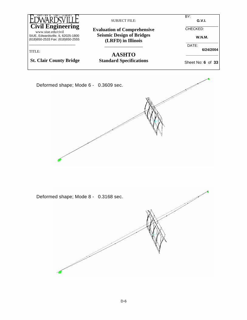
Civil Engineering www.siue.edu/civilSIUE, Edwardsville, IL 62025-1800(618)650-2533 Fax: (618)650-2555_______________________
TITLE:
St. Clair County Bridge
SUBJECT FILE:
Evaluation of Comprehensive Seismic Design of Bridges
(LRFD) in Illinois___________________
AASHTOStandard Specifications
BY: _________ G.V.I.______
________________CHECKED: _____
W.N.M._____________________DATE:__________
6/24/2004________________
Sheet No: 6 of 33
Deformed shape; Mode 6 - 0.3609 sec.
Deformed shape; Mode 8 - 0.3168 sec.
D-6
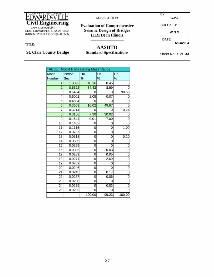
Civil Engineering www.siue.edu/civilSIUE, Edwardsville, IL 62025-1800(618)650-2533 Fax: (618)650-2555_______________________
TITLE:
St. Clair County Bridge
SUBJECT FILE:
Evaluation of Comprehensive Seismic Design of Bridges
(LRFD) in Illinois___________________
AASHTOStandard Specifications
BY: _________ G.V.I.______
________________CHECKED: _____
W.N.M._____________________DATE:__________
6/24/2004________________
Sheet No: 7 of 33
TABLE: Modal Participating Mass RatiosMode Period UX UY UZNumber Sec % % %
1 1.0392 40.16 0.45 02 0.6622 34.43 8.99 03 0.6434 0 0 98.664 0.6002 2.08 0.07 05 0.4894 0 0 06 0.3609 16.02 49.67 07 0.3214 0 0 0.248 0.3168 7.30 30.02 09 0.1644 0.01 7.00 0
10 0.1482 0 0 011 0.1115 0 0 1.0012 0.0707 0 0 013 0.0613 0 0 0.1014 0.0506 0 0 015 0.0359 0 0 016 0.0305 0 0.03 017 0.0289 0 0.05 018 0.0271 0 2.69 019 0.0259 0 0 020 0.0246 0 0 021 0.0243 0 0.17 022 0.0237 0 0.06 023 0.0230 0 0 024 0.0225 0 0.03 025 0.0205 0 0 0
100.00 99.23 100.00
D-7

Civil Engineering www.siue.edu/civilSIUE, Edwardsville, IL 62025-1800(618)650-2533 Fax: (618)650-2555_______________________
TITLE:
St. Clair County Bridge
SUBJECT FILE:
Evaluation of Comprehensive Seismic Design of Bridges
(LRFD) in Illinois___________________
AASHTOStandard Specifications
BY: _________ G.V.I.______
________________CHECKED: _____
W.N.M._____________________DATE:__________
6/24/2004________________
Sheet No: 8 of 33
Piles (L-pile results)
Longitudinal direction of the bridge:
D-8

Civil Engineering www.siue.edu/civilSIUE, Edwardsville, IL 62025-1800(618)650-2533 Fax: (618)650-2555_______________________
TITLE:
St. Clair County Bridge
SUBJECT FILE:
Evaluation of Comprehensive Seismic Design of Bridges
(LRFD) in Illinois___________________
AASHTOStandard Specifications
BY: _________ G.V.I.______
________________CHECKED: _____
W.N.M._____________________DATE:__________
6/24/2004________________
Sheet No: 9 of 33
Transverse direction of the bridge:
D-9

Civil Engineering www.siue.edu/civilSIUE, Edwardsville, IL 62025-1800(618)650-2533 Fax: (618)650-2555_______________________
TITLE:
St. Clair County Bridge
SUBJECT FILE:
Evaluation of Comprehensive Seismic Design of Bridges
(LRFD) in Illinois___________________
AASHTOStandard Specifications
BY: _________ G.V.I.______
________________CHECKED: _____
W.N.M._____________________DATE:__________
6/24/2004________________
Sheet No: 10 of 33
Assumed location of Global and Local coordinate systems (due to the skew of the Pier):
Longitudinal - X axis direction;Transverse - Y axis direction.
D-10

Civil Engineering www.siue.edu/civilSIUE, Edwardsville, IL 62025-1800(618)650-2533 Fax: (618)650-2555_______________________
TITLE:
St. Clair County Bridge
SUBJECT FILE:
Evaluation of Comprehensive Seismic Design of Bridges
(LRFD) in Illinois___________________
AASHTOStandard Specifications
BY: _________ G.V.I.______
________________CHECKED: _____
W.N.M._____________________DATE:__________
6/24/2004________________
Sheet No: 11 of 33
k ft−
MXlocalX MXglob sin φ( )⋅:=
MYlocaX MXglob cos φ( )⋅:=
Meql MYlocalY MYlocaX+:= Meql 9.017 103×= k ft− longitudinal
Meqt MXlocaY MXlocalX+:= Meqt 3.709 103×= k ft− transverse
Pw 3291:= kips
The distance from center line of foundation to center of pile (ft):
d1 3.281:= d2 3.002:= d3 9.006:= d4 14.747:= d5 20.488:= d6 26.229:= d7 31.97:=
Axial Force On A Pile :
φ 26.528:= degrees Skew of the bridge
Rsc 5:= Response Modification Factor for a pile bent:
Rr Rsc 0.5⋅:= Reduced Response Modification Factor (AASHTO article 6.6.2)
MYglob21913
Rr:= MYglob 8.765 103×= k ft− Longitudinal
MYlocalY MYglob sin φ( )⋅:= MYlocalY 8.631 103×= k ft−
MXglob5531Rr
:= MXglob 2.212 103×= k ft− Transverse
MXlocaY MYglob cos φ( )⋅:= MXlocaY 1.531 103×=
D-11

Civil Engineering www.siue.edu/civilSIUE, Edwardsville, IL 62025-1800(618)650-2533 Fax: (618)650-2555_______________________
TITLE:
St. Clair County Bridge
SUBJECT FILE:
Evaluation of Comprehensive Seismic Design of Bridges
(LRFD) in Illinois___________________
AASHTOStandard Specifications
BY: _________ G.V.I.______
________________CHECKED: _____
W.N.M._____________________DATE:__________
6/24/2004________________
Sheet No: 12 of 33
COMB 2: F(longitud.) = 1148.89 kips, F(transverse) = 1021.76 kips, M(longitud.) = 2988.43 k-ft, M(transverse) = 11482.57 k-ft
COMB 1: F(longitud.) = 1367.04 kips, F(transverse) = 1327.71 kips, M(longitud.) = 5530.71 k-ft, M(transverse) = 21912.78 k-ft
Forces from SAP2000 model:
Note: Q.ult = Q.s + Q.t - W.self (Compression) and .7*Q.s + W (uplift); Q.allow = Q.ult / FS
kipsFpile36 31.2−=Fpile36Pw36
⎛⎜⎝
⎞
⎠Meql
d1Σd1⋅
⎛⎜⎝
⎞⎠
− Meqtd7Σd2⋅
⎛⎜⎝
⎞⎠
−:=
kipsFpile25 14.98−=Fpile25Pw36
⎛⎜⎝
⎞
⎠Meql
d1Σd1⋅
⎛⎜⎝
⎞⎠
− Meqtd7Σd2⋅
⎛⎜⎝
⎞⎠
+:=
kipsFpile12 197.82=Fpile12Pw36
⎛⎜⎝
⎞
⎠Meql
d1Σd1⋅
⎛⎜⎝
⎞⎠
+ Meqtd7Σd2⋅
⎛⎜⎝
⎞⎠
−:=
kipsFpile1 214=Fpile1Pw36
⎛⎜⎝
⎞
⎠Meql
d1Σd1⋅
⎛⎜⎝
⎞⎠
+ Meqtd7Σd2⋅
⎛⎜⎝
⎞⎠
+:=
Piles Loads:
(transverse) ft2Σd2 1.462 104×=
Σd2 6 d22( )⋅ 6 d32( )⋅+ 6 d42( )⋅+ 6 d52( )⋅+ 6 d62( )⋅+ 6 d72( )⋅+:=
(longitudinal) ft2Σd1 258.359=Σd1 24 d12( )⋅:=
Sum of squares of the distances to each pile from the center line of the foundation:
D-12
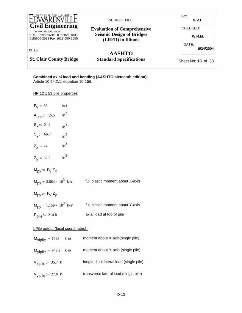
Civil Engineering www.siue.edu/civilSIUE, Edwardsville, IL 62025-1800(618)650-2533 Fax: (618)650-2555_______________________
TITLE:
St. Clair County Bridge
SUBJECT FILE:
Evaluation of Comprehensive Seismic Design of Bridges
(LRFD) in Illinois___________________
AASHTOStandard Specifications
BY: _________ G.V.I.______
________________CHECKED: _____
W.N.M._____________________DATE:__________
6/24/2004________________
Sheet No: 13 of 33
Mpy 1.159 103×= k in⋅ full plastic moment about Y-axis
Ppile 214:= k axial load at top of pile
LPile output (local coordinates):
Mxlpile 1623:= k in⋅ moment about X-axis(single pile)
Mylpile 948.2:= k in⋅ moment about Y-axis (single pile)
Vxlpile 35.7:= k longitudinal lateral load (single pile)
Vylpile 27.8:= k transverse lateral load (single pile)
Combined axial load and bending (AASHTO sixteenth edition):Article 10.54.2.1; equation 10-156.
HP 12 x 53 pile properties:
Fy 36:= ksi
Apile 15.5:= in2
Sx 21.1:= in3
Sy 66.7:= in3
Zx 74:= in3
Zy 32.2:= in3
Mpx Fy Zx⋅:=
Mpx 2.664 103×= k in⋅ full plastic moment about X-axis
Mpy Fy Zy⋅:=
D-13
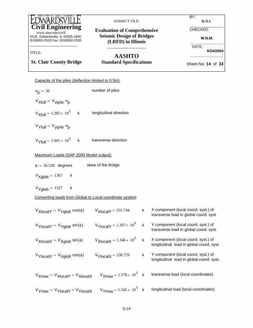
Civil Engineering www.siue.edu/civilSIUE, Edwardsville, IL 62025-1800(618)650-2533 Fax: (618)650-2555_______________________
TITLE:
St. Clair County Bridge
SUBJECT FILE:
Evaluation of Comprehensive Seismic Design of Bridges
(LRFD) in Illinois___________________
AASHTOStandard Specifications
BY: _________ G.V.I.______
________________CHECKED: _____
W.N.M._____________________DATE:__________
6/24/2004________________
Sheet No: 14 of 33
k X component (local coord. syst.) of transverse load in global coord. syst.
VYlocalY VYglob sin φ( )⋅:= VYlocalY 1.307 103×= k Y component (local coord. syst.) of transverse load in global coord. syst.
VXlocalX VXglob sin φ( )⋅:= VXlocalX 1.346 103×= k X component (local coord. syst.) of longitudinal load in global coord. syst.
VYlocalX VXglob cos φ( )⋅:= VYlocalX 238.729= k Y component (local coord. syst.) of longitudinal load in global coord. syst.
VXmax VXlocalY VXlocalX+:= VXmax 1.578 103×= k transverse load (local coordinates)
VYmax VYlocalY VYlocalX+:= VYmax 1.545 103×= k longitudinal load (local coordinates)
Capacity of the piles (deflection limited to 0.5in):
np 36:= number of piles
VXfull Vxlpile np⋅:=
VXfull 1.285 103×= k longitudinal direction
VYfull Vylpile np⋅:=
VYfull 1.001 103×= k transverse direction
Maximum Loads (SAP 2000 Model output):
φ 26.528:= degrees skew of the bridge
VXglob 1367:= k
VYglob 1327:= k
Converting loads from Global to Local coordinate system:
VXlocalY VYglob cos φ( )⋅:= VXlocalY 231.744=
D-14

Civil Engineering www.siue.edu/civilSIUE, Edwardsville, IL 62025-1800(618)650-2533 Fax: (618)650-2555_______________________
TITLE:
St. Clair County Bridge
SUBJECT FILE:
Evaluation of Comprehensive Seismic Design of Bridges
(LRFD) in Illinois___________________
AASHTOStandard Specifications
BY: _________ G.V.I.______
________________CHECKED: _____
W.N.M._____________________DATE:__________
6/24/2004________________
Sheet No: 15 of 33
*
Rp 5:= Response Modification Factor (R) for vertical piles (AASHTO Division A1, table 3.7)Can be increased by factor of 0.5 (Article 6.2.2 Design forces for foundations)
Rpm Rp 0.5⋅:= Response Modification Factor (R) with factor of 0.5 applied:
Mx
MxlpileVXmaxVXfull
⎛⎜⎜⎝
⎞
⎠⋅
Rpm:= Mx 796.971= k in⋅
My
MylpileVYmaxVYfull
⎛⎜⎜⎝
⎞
⎠⋅
Rpm:= My 585.647= k in⋅
Ppile0.85 Apile⋅ Fy⋅
⎛⎜⎜⎝
⎞
⎠
89
MxMpx
⎛⎜⎜⎝
⎞
⎠
MyMpy
⎛⎜⎜⎝
⎞
⎠+
⎡⎢⎢⎣
⎤⎥⎥⎦
⋅+ 1.166= In order to satisfy AASHTO design requirements the resultant of this equationmust be less than or equal 1.
* We used 5 here because AASHTO recommends R=5 for a multi-column bent. To be conservative, a 3 could be used, if the bent considered a single column for X-axis bending.
D-15

Civil Engineering www.siue.edu/civilSIUE, Edwardsville, IL 62025-1800(618)650-2533 Fax: (618)650-2555_______________________
TITLE:
St. Clair County Bridge
SUBJECT FILE:
Evaluation of Comprehensive Seismic Design of Bridges
(LRFD) in Illinois___________________
AASHTOStandard Specifications
BY: _________ G.V.I.______
________________CHECKED: _____
W.N.M._____________________DATE:__________
6/24/2004________________
Sheet No: 16 of 33
Vutrans 2.7803 104lb⋅:= Vutrans 2.78 104× lb= Transverse
Mulong 1.623 106⋅ lb in⋅:= Mulong 1.353 105× lb ft⋅= Longitudinal
Vulong 3.5646 104lb⋅:= Vulong 3.565 104× lb= Longitudinal
Spring Stiffness:
kaxial ApileEs
Lpile⋅:= kaxial 5.763 106×
lbft
= Axial
klongVulong
∆:= klong 8.555 105×
lbft
= Longitudinal
ktransVutrans
∆:= ktrans 6.673 105×
lbft
= Transverse
Springs (at bottom of foundation)
Actual L-Pile input - output information is given in the Appendix A.
Pile Information for L-Pile input:ft 12in:=
HP 12x53 - pilesk 1000lb:=
Lpile 936 in⋅:= Lpile 78 ft= m 3.281 length=
Apile 15.5 in2⋅:= Apile 0.108 ft2=
Es 29000000lb
in2⋅:= Es 4176000000
lb
ft2=
∆ 0.5 in⋅:= top of pile displacement limit.
Results from L-Pile (displacement is limited to 0.5 in):
Mutrans 9.482 105⋅ lb in⋅:= Mutrans 7.902 104× lb ft⋅= Transverse
D-16

Civil Engineering www.siue.edu/civilSIUE, Edwardsville, IL 62025-1800(618)650-2533 Fax: (618)650-2555_______________________
TITLE:
St. Clair County Bridge
SUBJECT FILE:
Evaluation of Comprehensive Seismic Design of Bridges
(LRFD) in Illinois___________________
AASHTOStandard Specifications
BY: _________ G.V.I.______
________________CHECKED: _____
W.N.M._____________________DATE:__________
6/24/2004________________
Sheet No: 17 of 33
l2 6.004 ft⋅:= d2 9.006 ft⋅:= n2 d22 w2+:= n2 9.585 ft=
l3 5.741 ft⋅:= d3 14.747 ft⋅:= n3 d32 w2+:= n3 15.107 ft=
l4 5.741 ft⋅:= d4 20.488 ft⋅:= n4 d42 w2+:= n4 20.749 ft=
l5 5.741 ft⋅:= d5 26.229 ft⋅:= n5 d52 w2+:= n5 26.433 ft=
l6 5.741 ft⋅:= d6 31.97 ft⋅:= n6 d62 w2+:= n6 32.138 ft=
Lateral Springs:
klongB 173.8 103⋅lbft⋅:= for battered pile
Klong 24 klongB klong+( )⋅ 12klong+:= K1 3.497 104×kft⋅:=
Ktrans 36 ktrans⋅:= K2 2.402 104×kft⋅:=
Axial Springs:
Kaxial 36 kaxial⋅:= K3 2.075 105×kft⋅:=
Rotational Springs:
Distancebetweenpiles(transverse)
Distancebetweenfooting C.L.andpiles C.L.
Distancebetweenpiles(longitudinal)
Distancefrom centerof footing tocenter ofpiles
l1 3.002 ft⋅:= d1 3.002 ft⋅:= w 3.28 ft⋅:= n1 d12 w2+:= n1 4.446 ft=
D-17

Civil Engineering www.siue.edu/civilSIUE, Edwardsville, IL 62025-1800(618)650-2533 Fax: (618)650-2555_______________________
TITLE:
St. Clair County Bridge
SUBJECT FILE:
Evaluation of Comprehensive Seismic Design of Bridges
(LRFD) in Illinois___________________
AASHTOStandard Specifications
BY: _________ G.V.I.______
________________CHECKED: _____
W.N.M._____________________DATE:__________
6/24/2004________________
Sheet No: 18 of 33
Krx kaxial 6⋅ d1( )2 d2( )2+ d3( )2+ d4( )2+ d5( )2+ d6( )2+⎡⎣
⎤⎦⋅:=
Kr1 8.428 107×kft⋅:= about X axis
Kry kaxial 33⋅ 3.282⋅:= Kry 2.046 109× mass length-1=
Kr2 24.55 106×kft⋅:= about Y axis
Krz klong 4 n1( )2 n2( )2+ n3( )2+ n4( )2+ n5( )2+ n6( )2+⎡⎣
⎤⎦⋅
2 d1( )2 d2( )2+ d3( )2+ d4( )2+ d5( )2+ d6( )2+⎡⎣
⎤⎦⋅+
...⎡⎢⎢⎣
⎤⎥⎥⎦
⋅:=
Kr3 1.273 107×kft⋅:= about Z axis
D-18

Civil Engineering www.siue.edu/civilSIUE, Edwardsville, IL 62025-1800(618)650-2533 Fax: (618)650-2555_______________________
TITLE:
St. Clair County Bridge
SUBJECT FILE:
Evaluation of Comprehensive Seismic Design of Bridges
(LRFD) in Illinois___________________
AASHTOStandard Specifications
BY: _________ G.V.I.______
________________CHECKED: _____
W.N.M._____________________DATE:__________
6/24/2004________________
Sheet No: 19 of 33
Substructure
Supports (both abutments): Longitudinal - Roller ; Transverse - Pin
Support/LocationTop of Cap Beam
1(external) 80.00 26.67 285.00 95.00 150.00 30.00 534.00 106.80 23.003(middle) 199.00 66.33 708.00 236.00 172.00 34.40 613.00 122.60 0.00
Top of column1(external) 127.00 42.33 1041.00 347.00 174.00 34.80 754.00 150.80 168.003(middle) 166.00 55.33 1521.00 507.00 174.00 34.80 754.00 150.80 0.00
Bottom of column1(external) 127.00 42.33 515.00 171.67 175.00 35.00 2903.00 580.60 163.003(middle) 166.00 55.33 518.00 172.67 175.00 35.00 2903.00 580.60 0.00
Bottom of wall1(external) 127.00 42.33 1244.00 414.67 174.00 34.80 3913.00 782.60 161.003(middle) 167.00 55.67 1478.00 492.67 175.00 35.00 3912.00 782.40 0.00
Support/LocationTop of Cap Beam
1(external) 46.00 15.33 162.00 54.00 82.00 16.40 292.00 58.40 14.003(middle) 175.00 58.33 620.00 206.67 123.00 24.60 437.00 87.40 0.00
Top of column1(external) 120.00 40.00 970.00 323.33 95.00 19.00 410.00 82.00 157.003(middle) 157.00 52.33 1422.00 474.00 95.00 19.00 410.00 82.00 0.00
Bottom of column1(external) 177.00 59.00 483.00 161.00 93.00 18.60 1560.00 312.00 153.003(middle) 155.00 51.67 489.00 163.00 93.00 18.60 1560.00 312.00 0.00
Bottom of wall1(external) 116.00 38.67 1155.00 385.00 92.00 18.40 2090.00 418.00 151.003(middle) 154.00 51.33 1376.00 458.67 92.00 18.40 2089.00 417.80 0.00
Support/LocationTop of column
1 0.17 3.23 0 0 5163 0.17 3.23 0 0 516
Bottom of column1 0.9 4.5 0 0 5423 0 0 0 0 542
Bottom of wall 0.9 0.7 0 0 551
R = 2.0 (Wall-type Pier); (Substructure)
R = 1.0 (Columns, piers or pile bents to cap beam or superstructure); (Connections)R = 5.0 (Multiple column bent); (Substructure)
R = 0.8 (Superstructure to abutment); (Connections)
R = 3.0 (Single Columns); (Substructure)
Longitudinal (Weak Direction of Pier) Transverse (Strong Direction of Pier)Moment X (kip-ft) (kips)Moment Y (kip-ft) Shear Y (kips)Shear X (kips)
Axial
Shear X (kips) V3 Moment Y (kip-ft) M2 Shear Y (kips) V2
Forces and Moments - Dead Loads
Forces and Moments - Load Combination 1 - (1.0*EQL + 0.3*EQT)
Forces and Moments - Load Combination 2 - (0.3*EQL + 1.0*EQT)Longitudinal (Weak Direction of Pier) Transverse (Strong Direction of Pier) Axial
Moment X (kip-ft) M3 (kips)Longitudinal (Weak Direction of Pier) Transverse (Strong Direction of Pier) Axial
Shear Y (kips) V2Shear X (kips) V3 Moment Y (kip-ft) M2
Moment X (kip-ft) M3 (kips)
D-19

Civil Engineering www.siue.edu/civilSIUE, Edwardsville, IL 62025-1800(618)650-2533 Fax: (618)650-2555_______________________
TITLE:
St. Clair County Bridge
SUBJECT FILE:
Evaluation of Comprehensive Seismic Design of Bridges
(LRFD) in Illinois___________________
AASHTOStandard Specifications
BY: _________ G.V.I.______
________________CHECKED: _____
W.N.M._____________________DATE:__________
6/24/2004________________
Sheet No: 20 of 33
TABLE: Joint DisplacementsJoint OutputCase CaseType StepType U1 U2 U3 R1 R2 R3Text Text Text Text in in in Radians Radians Radians
1 COMB1 Combination Max 0.4749 0.5925 -0.6920 0.0037 0.0003 0.00001 COMB2 Combination Max 0.3950 0.4745 -1.2310 0.0020 0.0001 0.00002 COMB1 Combination Max 0.4749 0.5923 -0.8226 0.0037 0.0003 0.00002 COMB2 Combination Max 0.3950 0.4744 -1.3017 0.0020 0.0001 0.00003 COMB1 Combination Max 0.4749 0.5922 -0.9536 0.0037 0.0003 0.00003 COMB2 Combination Max 0.3950 0.4744 -1.3727 0.0020 0.0001 0.00004 COMB1 Combination Max 0.4749 0.5921 -1.0841 0.0037 0.0003 0.00004 COMB2 Combination Max 0.3950 0.4743 -1.4433 0.0020 0.0001 0.00005 COMB1 Combination Max 0.4749 0.5920 -1.3435 0.0037 0.0003 0.00005 COMB2 Combination Max 0.3950 0.4743 -1.5830 0.0020 0.0001 0.0000
TABLE: Base ReactionsNumber OutputCase CaseType StepType GlobalFX GlobalFY GlobalFZ GlobalMX GlobalMY GlobalMZ
Text Text Text Kip Kip Kip Kip-ft Kip-ft Kip-ftDEAD LinStatic 0 0 4545 0 0 0COMB1 Combination Max 1393 1183 4545 30459 27144 0COMB2 Combination Max 1076 1750 4545 31323 13564 0
TABLE: Joint Reactions - Spring ForcesJoint OutputCase CaseType StepType U1 U2 U3 R1 R2 R3Text Text Text Text Kip Kip Kip Kip-ft Kip-ft Kip-ft
J3 DEAD LinStatic 0 0 3225 0 0 0J3 COMB1 Combination Max 1367 1328 3225 5531 21913 0J3 COMB2 Combination Max 1149 1022 3225 2988 11483 0
D-20
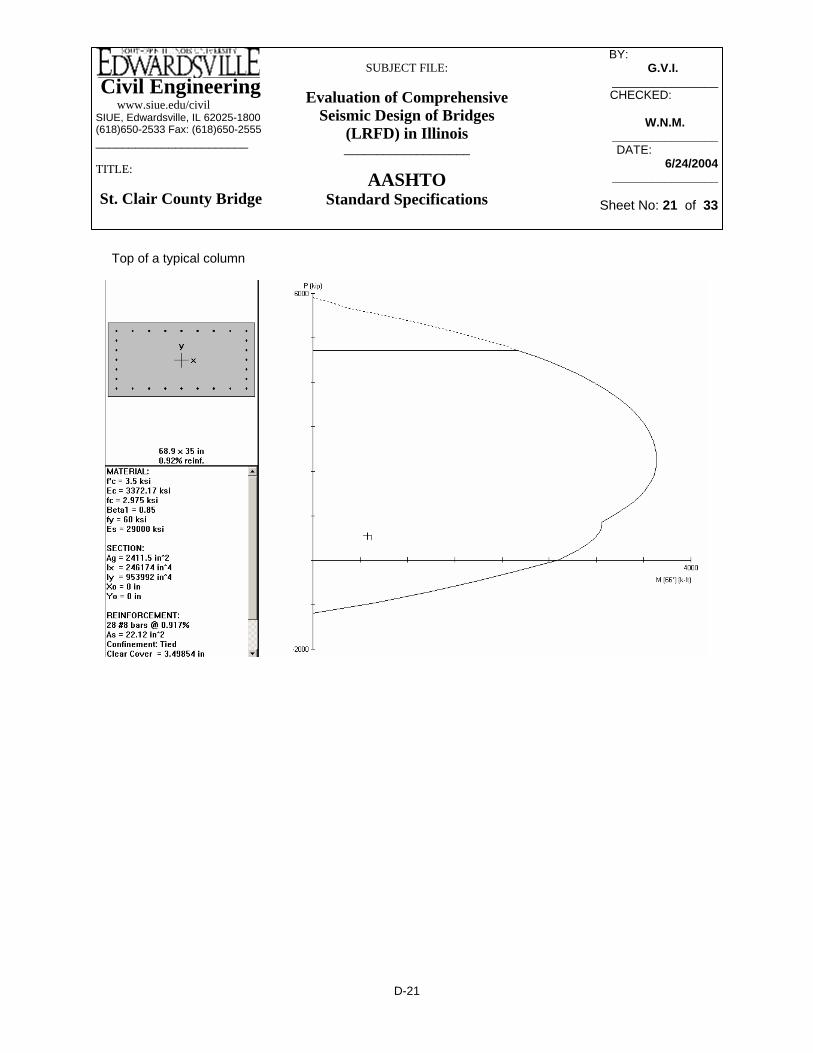
Civil Engineering www.siue.edu/civilSIUE, Edwardsville, IL 62025-1800(618)650-2533 Fax: (618)650-2555_______________________
TITLE:
St. Clair County Bridge
SUBJECT FILE:
Evaluation of Comprehensive Seismic Design of Bridges
(LRFD) in Illinois___________________
AASHTOStandard Specifications
BY: _________ G.V.I.______
________________CHECKED: _____
W.N.M._____________________DATE:__________
6/24/2004________________
Sheet No: 21 of 33
Top of a typical column
D-21

Civil Engineering www.siue.edu/civilSIUE, Edwardsville, IL 62025-1800(618)650-2533 Fax: (618)650-2555_______________________
TITLE:
St. Clair County Bridge
SUBJECT FILE:
Evaluation of Comprehensive Seismic Design of Bridges
(LRFD) in Illinois___________________
AASHTOStandard Specifications
BY: _________ G.V.I.______
________________CHECKED: _____
W.N.M._____________________DATE:__________
6/24/2004________________
Sheet No: 22 of 33
Bottom of a typical column
D-22

Civil Engineering www.siue.edu/civilSIUE, Edwardsville, IL 62025-1800(618)650-2533 Fax: (618)650-2555_______________________
TITLE:
St. Clair County Bridge
SUBJECT FILE:
Evaluation of Comprehensive Seismic Design of Bridges
(LRFD) in Illinois___________________
AASHTOStandard Specifications
BY: _________ G.V.I.______
________________CHECKED: _____
W.N.M._____________________DATE:__________
6/24/2004________________
Sheet No: 23 of 33
Bottom of Crash Wall
D-23

Civil Engineering www.siue.edu/civilSIUE, Edwardsville, IL 62025-1800(618)650-2533 Fax: (618)650-2555_______________________
TITLE:
St. Clair County Bridge
SUBJECT FILE:
Evaluation of Comprehensive Seismic Design of Bridges
(LRFD) in Illinois___________________
AASHTOStandard Specifications
BY: _________ G.V.I.______
________________CHECKED: _____
W.N.M._____________________DATE:__________
6/24/2004________________
Sheet No: 24 of 33
Fy2 250 106( )⋅ pconv⋅:= Fy2 3.625 104×= psi( )Structural( )
Ec 57000 fc( )⋅:= Ec 3.363 106×= Modulus of Elasticity of concrete.
Es 29000000:= Es 2.9 107×= Modulus of Elasticity of steel.
nEsEc
:= n 8.624= Modular Ratio
boltD 24 10 3−( )⋅ inch⋅:= boltD 0.945= Bolt Diameter (in.)
Skew 263160
⎛⎜⎝
⎞⎠
+40
3600⎛⎜⎝
⎞⎠
+:= Skew 26.528= Skew Angle (degrees)
Section Properties of Superstructure
Pertinent Information about Materials used, etc. :
pconv 1.45 10 4−×( ):= N/m^2 to psi conversion factor.
feet1
.3048:= feet 3.281= meter to feet conversion.
inch feet 12⋅:= inch 39.37= meter to inches conversion.
fc 24 106( )⋅ pconv⋅:= fc 3480.000=
fy 400 106( )⋅ pconv⋅:= fy 5.8 104×= Reinforcement( ) psi( )
Fy1 345 106( ) pconv⋅:= Fy1 5.003 104×= psi( )Structural( )
D-24

Civil Engineering www.siue.edu/civilSIUE, Edwardsville, IL 62025-1800(618)650-2533 Fax: (618)650-2555_______________________
TITLE:
St. Clair County Bridge
SUBJECT FILE:
Evaluation of Comprehensive Seismic Design of Bridges
(LRFD) in Illinois___________________
AASHTOStandard Specifications
BY: _________ G.V.I.______
________________CHECKED: _____
W.N.M._____________________DATE:__________
6/24/2004________________
Sheet No: 25 of 33
efw3 98.031= outer( )
efw3b 12 tavg⋅( ) .5 bf2⋅( )+:= efw3b 103.937= inner( )
efw4 gspace:= efw4 75= This controls
EFWinside gspace:= EFWinside 75=
Effective Flange Width of exterior maybe be taken as .5 EFW plus least of (in inches):
efw518
Leff⋅:= efw5 204.232=
efw6 6 tavg⋅( ) .5 tw⋅( )+:= efw6 46.339=
efw7 6 tavg⋅( ) .25 bf1⋅( )+:= efw7 49.016=
efw8 6 tavg⋅( ) .25 bf2⋅( )+:= efw8 51.969=
ohw .925 inch⋅:= ohw 36.417= This controls
EFWoutside .5 EFWinside⋅( ) ohw+:= EFWoutside 73.917=
Calculations for Moment of Inertia for Superstructure
Leff 41.50 inch⋅:= Leff 1.634 103×= Effective length of a span (in)
tavg .195 inch⋅:= tavg 7.677= Slab thickness (in)
tw .014 inch⋅:= tw 0.551= Web thickness (in)
bf1 .300 inch⋅:= bf1 11.811= Top flange width outerline (in)
bf2 .600 inch⋅:= bf2 23.622= Top flange width innerline (in)
gspace 1.905 inch⋅:= gspace 75= Girderline spacing (in)
Effective Flange Width of interior maybe be taken as least of (in inches):
efw1 .25 Leff⋅:= efw1 408.465=
efw2 12 tavg⋅( ) tw+:= efw2 92.677=
efw3 12tavg( ) .5 bf1⋅( )+:=
D-25

Civil Engineering www.siue.edu/civilSIUE, Edwardsville, IL 62025-1800(618)650-2533 Fax: (618)650-2555_______________________
TITLE:
St. Clair County Bridge
SUBJECT FILE:
Evaluation of Comprehensive Seismic Design of Bridges
(LRFD) in Illinois___________________
AASHTOStandard Specifications
BY: _________ G.V.I.______
________________CHECKED: _____
W.N.M._____________________DATE:__________
6/24/2004________________
Sheet No: 26 of 33
ft
hslab .195 feet⋅:=
hslab 0.64= ft areaslab hslab bslab⋅:= areaslab 5.062= ft2
areagirder1 11 .02 .3⋅( ) .02 .6⋅( )+ 1.372 .014⋅( )+[ ]⋅ feet⋅ feet⋅:= areagirder1 4.406= ft2
areagirder2 11 .045 .6⋅( ) .045 .6⋅( )+ 1.372 .014⋅( )+[ ]⋅ feet⋅ feet⋅:= areagirder2 8.668= ft2
areasuper1 areaslab areagirder1+( ):= areasuper1 9.468= ft2
areasuper2 areaslab areagirder2+( ):= areasuper2 13.73= ft2
We can use all of the slab for moment of inertia.
Iyy1 36.2084:= Izz1 3676.5792:=
Iyy2 61.4485:= Izz2 5343.1700:=
Torsional Properties:
We assume only the deck will resist torsion.
bdeck 20.8 feet⋅:= bdeck 68.241= ft
hdeck .195 feet⋅:= hdeck 0.64= ft
J bdeck( )hdeck( )3
3⋅:= J 5.956= ft4
Cross-Sectional Area of Superstructure:
bslab 20.8feetn
⋅:=
bslab 7.913=
D-26
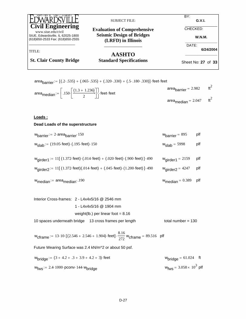
Civil Engineering www.siue.edu/civilSIUE, Edwardsville, IL 62025-1800(618)650-2533 Fax: (618)650-2555_______________________
TITLE:
St. Clair County Bridge
SUBJECT FILE:
Evaluation of Comprehensive Seismic Design of Bridges
(LRFD) in Illinois___________________
AASHTOStandard Specifications
BY: _________ G.V.I.______
________________CHECKED: _____
W.N.M._____________________DATE:__________
6/24/2004________________
Sheet No: 27 of 33
wmedian areamedian .190⋅:= wmedian 0.389= plf
Interior Cross-frames: 2 - L4x4x5/16 @ 2546 mm
1 - L4x4x5/16 @ 1904 mm
weight(lb.) per linear foot = 8.16
10 spaces underneath bridge 13 cross frames per length total number = 130
wcframe 13 10⋅ 2.546 2.546+ 1.904+( ) feet⋅[ ]⋅8.16272
⋅:= wcframe 89.516= plf
Future Wearing Surface was 2.4 kN/m^2 or about 50 psf.
wbridge 3 4.2+ .3+ 3.9+ 4.2+ 3+( ) feet⋅:= wbridge 61.024= ft
wfws 2.4 1000⋅ pconv⋅ 144⋅ wbridge⋅:= wfws 3.058 103×= plf
areabarrier .2 .535⋅( ) .065 .535⋅( )+ .320 .330⋅( )+ .5 .180⋅ .330⋅( )+[ ] feet⋅ feet⋅:=
areabarrier 2.982= ft2
areamedian .1501.3 1.236+( )
2⎡⎢⎣
⎤⎥⎦
⋅⎡⎢⎣
⎤⎥⎦
feet⋅ feet⋅:=
areamedian 2.047= ft2
Loads :
Dead Loads of the superstructure
wbarrier 2 areabarrier⋅ 150⋅:= wbarrier 895= plf
wslab 19.05 feet⋅( ) .195 feet⋅( )⋅ 150⋅:= wslab 5998= plf
wgirder1 11 1.372 feet⋅( ) .014 feet⋅( )⋅ .020 feet⋅( ) .900 feet⋅( )⋅+[ ] 490⋅:= wgirder1 2159= plf
wgirder2 11 1.372 feet⋅( ) .014 feet⋅( ) .045 feet⋅( ) 1.200 feet⋅( )⋅+[ ] 490⋅:= wgirder2 4247= plf
D-27

Civil Engineering www.siue.edu/civilSIUE, Edwardsville, IL 62025-1800(618)650-2533 Fax: (618)650-2555_______________________
TITLE:
St. Clair County Bridge
SUBJECT FILE:
Evaluation of Comprehensive Seismic Design of Bridges
(LRFD) in Illinois___________________
AASHTOStandard Specifications
BY: _________ G.V.I.______
________________CHECKED: _____
W.N.M._____________________DATE:__________
6/24/2004________________
Sheet No: 28 of 33
Dimensions used to model:
column1 .. bcol1 1.75 feet⋅:= bcol1 5.741= ft
column2 .. bcol2 1.625 feet⋅:= bcol2 5.331= ft
column3 .. bcol3 1.5 feet⋅:= bcol3 4.921= ft
column4 .. bcol4 1.375 feet⋅:= bcol4 4.511= ft
column5 .. bcol5 1.25 feet⋅:= bcol5 4.101= ft
column6 .. bcol6 1.125 feet⋅:= bcol6 3.691= ft
All columns are a width of 2.953 ft over their entire length.
Columns designed as non-prismatic sections in SAP-2000.
Adding the individual pieces together we get:
wouter wbarrier wmedian+ wcframe+ wslab+ wgirder1+ wfws+:= wouter 12199= plf
winner wbarrier wmedian+ wcframe+ wslab+ wgirder2+ wfws+:= winner 14288= plf
W(outer) is the uniform dead load along the superstructure from the abutments to the place where the field splices are located. W(inner) occupy the center of each girder line which are the continuous part over the central pier.
Pier Column Dimensions and properties:
bcoltop 1.75 feet⋅:= bcoltop 5.741= ft
bcolbot 1.125 feet⋅:= bcolbot 3.691= ft
lcol 3.75 feet⋅:= lcol 12.303= ft
wcol .90 feet⋅:= wcol 2.953= ft
number of column increments used: incrcol 5:=
length of column increments: lincrlcol
incrcol:= lincr 2.461= ft
D-28
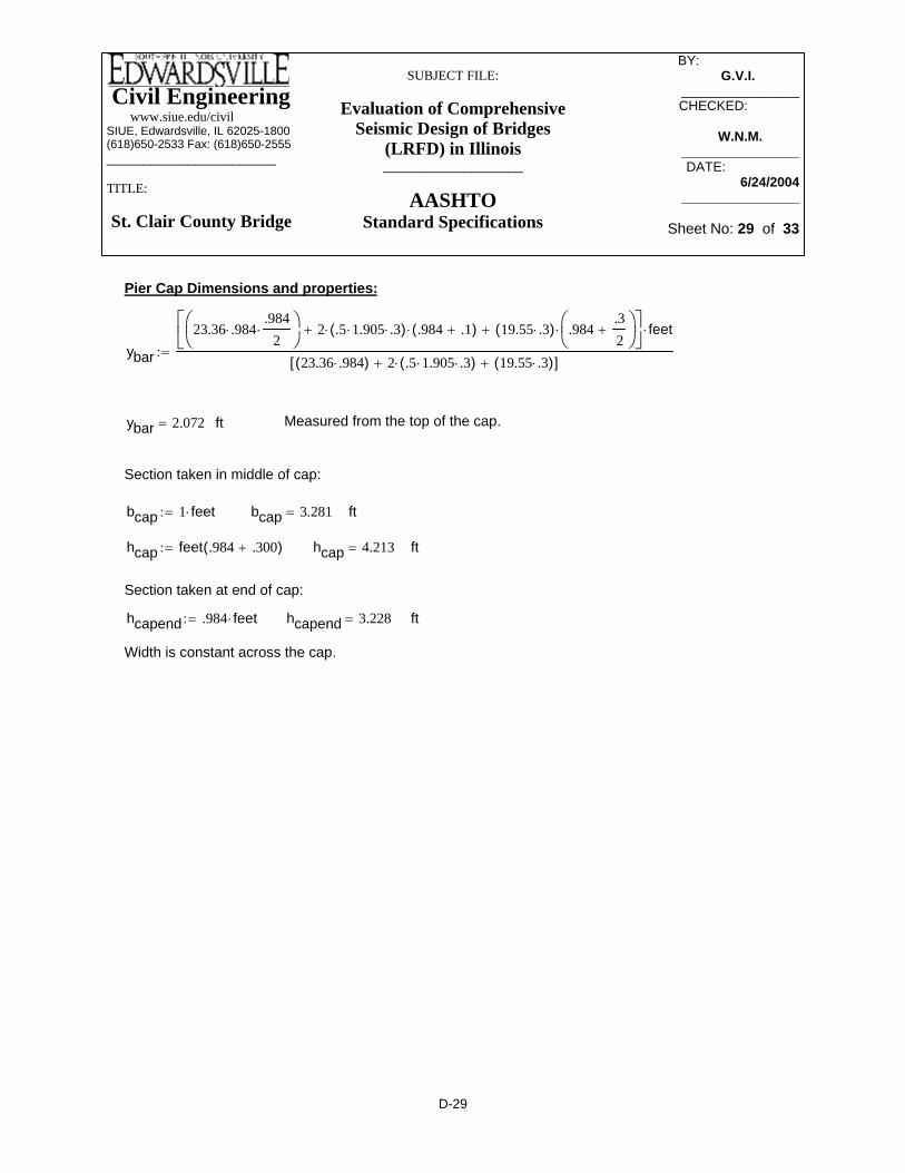
Civil Engineering www.siue.edu/civilSIUE, Edwardsville, IL 62025-1800(618)650-2533 Fax: (618)650-2555_______________________
TITLE:
St. Clair County Bridge
SUBJECT FILE:
Evaluation of Comprehensive Seismic Design of Bridges
(LRFD) in Illinois___________________
AASHTOStandard Specifications
BY: _________ G.V.I.______
________________CHECKED: _____
W.N.M._____________________DATE:__________
6/24/2004________________
Sheet No: 29 of 33
Width is constant across the cap.
fthcapend 3.228=hcapend .984 feet⋅:=
Section taken at end of cap:
fthcap 4.213=hcap feet .984 .300+( ):=
ftbcap 3.281=bcap 1 feet⋅:=
Section taken in middle of cap:
Measured from the top of the cap.ftybar 2.072=
ybar
23.36 .984⋅.984
2⋅⎛⎜
⎝⎞⎠
2 .5 1.905⋅ .3⋅( )⋅ .984 .1+( )⋅+ 19.55 .3⋅( ) .984.32
+⎛⎜⎝
⎞⎠
⋅+⎡⎢⎣
⎤⎥⎦
feet⋅
23.36 .984⋅( ) 2 .5 1.905⋅ .3⋅( )⋅+ 19.55 .3⋅( )+[ ]:=
Pier Cap Dimensions and properties:
D-29
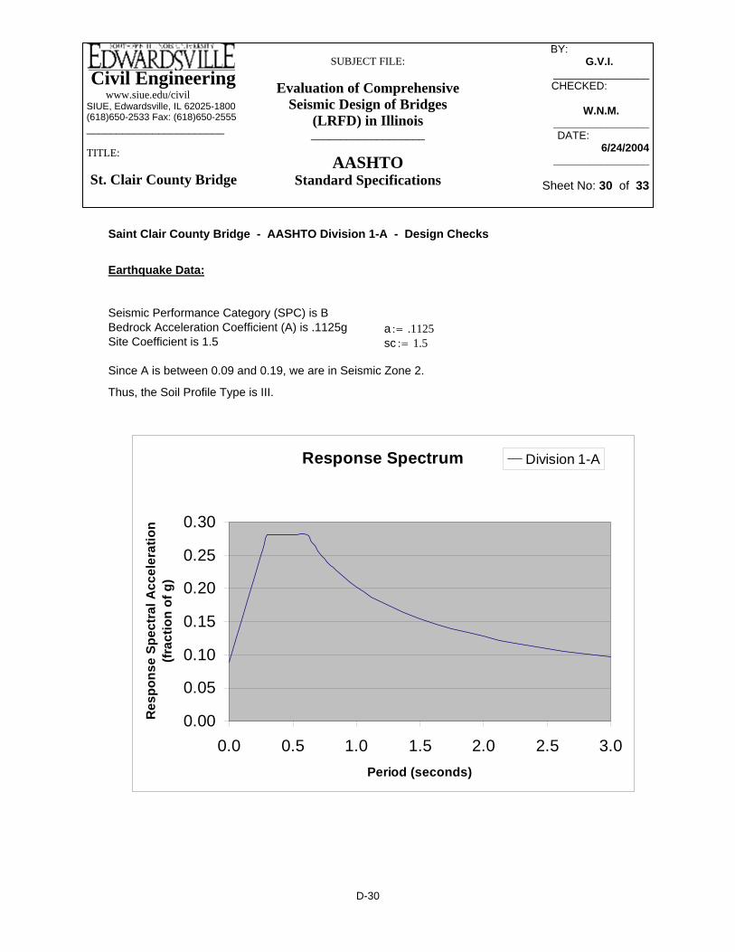
Civil Engineering www.siue.edu/civilSIUE, Edwardsville, IL 62025-1800(618)650-2533 Fax: (618)650-2555_______________________
TITLE:
St. Clair County Bridge
SUBJECT FILE:
Evaluation of Comprehensive Seismic Design of Bridges
(LRFD) in Illinois___________________
AASHTOStandard Specifications
BY: _________ G.V.I.______
________________CHECKED: _____
W.N.M._____________________DATE:__________
6/24/2004________________
Sheet No: 30 of 33
Saint Clair County Bridge - AASHTO Division 1-A - Design Checks
Earthquake Data:
Seismic Performance Category (SPC) is BBedrock Acceleration Coefficient (A) is .1125g a .1125:=Site Coefficient is 1.5 sc 1.5:=
Since A is between 0.09 and 0.19, we are in Seismic Zone 2.
Thus, the Soil Profile Type is III.
Response Spectrum
0.00
0.05
0.10
0.15
0.20
0.25
0.30
0.0 0.5 1.0 1.5 2.0 2.5 3.0Period (seconds)
Res
pons
e Sp
ectr
al A
ccel
erat
ion
(frac
tion
of g
)
Division 1-A
D-30

Civil Engineering www.siue.edu/civilSIUE, Edwardsville, IL 62025-1800(618)650-2533 Fax: (618)650-2555_______________________
TITLE:
St. Clair County Bridge
SUBJECT FILE:
Evaluation of Comprehensive Seismic Design of Bridges
(LRFD) in Illinois___________________
AASHTOStandard Specifications
BY: _________ G.V.I.______
________________CHECKED: _____
W.N.M._____________________DATE:__________
6/24/2004________________
Sheet No: 31 of 33
Applied shear is less than 2x V.c, thus column satisfies requirements for shear with only minimum reinforcement
kipsvcol2 35.725=vcol2 262 24.52+:=
kipsvcol1 60.415=vcol1 532 292+:=
Use value of 168 kips since it takes into account the axial load that is present.
lbsVc2 1.666 105×=Vc2 2 3500⋅ 44⋅ 32⋅:=
.85 Vc⋅ 1.689 105×=lbsVc 198672=Vc 2 1593000
2000 44⋅ 35⋅+⎛⎜
⎝⎞⎠
⋅ 3500⋅ 44⋅ 32⋅:=
Shear - Columns (8.16.6.2.2)
Moment at bottom of crashwall is okay according to PCA Column; Use 8.18.2.1 exception
R is equal to 2 in both strong and weak axis of pier
Moment - Crashwall
Moment at bottom of column is okay according to PCA Column Moment at top of column is okay according to PCA Column*** Note that top uses exception in Article 8.18.2.1 on the use of a minimum of steel that is less than the typical 1% for longitudinal reinforcement
R is equal to 3 in weak axis of central pier (centerline of deck + skew)R is equal to 5 in strong axis of central pier (perpendicular to weak axis)
Moment - Columns
D-31

Civil Engineering www.siue.edu/civilSIUE, Edwardsville, IL 62025-1800(618)650-2533 Fax: (618)650-2555_______________________
TITLE:
St. Clair County Bridge
SUBJECT FILE:
Evaluation of Comprehensive Seismic Design of Bridges
(LRFD) in Illinois___________________
AASHTOStandard Specifications
BY: _________ G.V.I.______
________________CHECKED: _____
W.N.M._____________________DATE:__________
6/24/2004________________
Sheet No: 32 of 33
lu 147.6:= in slenderness klur
⋅:= slenderness 27.8=
M1b 236−:= k ft−
M2b 471:= k ft−
βd 1:= Ec 1820 3500⋅:= Es 29000:= Cm .6 .4M1bM2b
⎛⎜⎜⎝
⎞
⎠⋅+:=
Cm 0.4=Ig112
44.3⋅ 35.43⋅:= Ig 1.638 105×= in4
EIEc
Ig2.5⋅
⎛⎜⎝
⎞
⎠1 βd+( ):= EI 3.527 109×=
Shear - Crashwall
Vc3 2 3500⋅ 769⋅ 36.4⋅:= Vc3 3.312 106×= lbs
.85 Vc3⋅ 2.815 106×= lbs
Use value of 2815 kips
vwall1 79.52 72.62+:= vwall1 107.662= kips
vwall2 392 612+:= vwall2 72.402= kips
Applied shear is less than 2x V.c, thus wall satisfies requirements for shear with only minimum reinforcement
Slenderness Effects (8.16.5)
r .3 35.4⋅:= r 10.62= in k 2:=
D-32

Civil Engineering www.siue.edu/civilSIUE, Edwardsville, IL 62025-1800(618)650-2533 Fax: (618)650-2555_______________________
TITLE:
St. Clair County Bridge
SUBJECT FILE:
Evaluation of Comprehensive Seismic Design of Bridges
(LRFD) in Illinois___________________
AASHTOStandard Specifications
BY: _________ G.V.I.______
________________CHECKED: _____
W.N.M._____________________DATE:__________
6/24/2004________________
Sheet No: 33 of 33
The distance from centerline of bearing to backwall is 474 mm, so the overall seat width is around 950 mm; the seat is adequate.
inN
25.416.549=mmN 420.353=
N 203 1.67 83⋅+ 6.66 6.72⋅+( ) 1 .000125 26.528⋅ 26.528⋅+( )⋅:=6.3.1
AASHTO Division 1-A; Section 6; SPC (B); Checklist
δs 1.0:=Use values obtain from SAP2000 with their respective R factors as the design moments
Use δ.b equals 1.0δb 0.4=δb.4
1567
276960−
:=
kφ Pc⋅ 2.77 105×=
Use φ equals .70 (pure compression)φ 0.693=φ .9 2567
3.5 44.3⋅ 35.4⋅⋅−:=
kPc 3.994 105×=Pcπ
2 EI⋅( )2 lu⋅( )2
:=
D-33

Civil Engineering www.siue.edu/civilSIUE, Edwardsville, IL 62025-1800(618)650-2533 Fax: (618)650-2555
______________________________
Title: Pulaski County Bridge
SUBJECT FILE:
Evaluation of Comprehensive Siesmic Design of Bridges
(LRFD) in Illinois___________________
NCHRP Guidelines
BY:_____________ NA________
____________________CHECKED: _____
AAA_______ ____________________
DATE:__________ 6/22/2004
___________________
Sheet No: 1
Appendix E -- Detailed Computations for Seismic Analysis and Design of the Pulaski County Bridge using Proposed NCHRP Specification
E-1

Civil Engineering www.siue.edu/civilSIUE, Edwardsville, IL 62025-1800(618)650-2533 Fax: (618)650-2555
______________________________
Title: Pulaski County Bridge
SUBJECT FILE:
Evaluation of Comprehensive Siesmic Design of Bridges
(LRFD) in Illinois___________________
NCHRP Guidelines
BY:_____________ NA________
____________________CHECKED: _____
AAA_______ ____________________
DATE:__________ 6/22/2004
___________________
Sheet No: 2
Table of Contents of Appendix- E
Design response spectrum (MCE) E-3 Design response spectrum (FE) E-4 Section properties of superstructure E-5 Dead load calculation E-9 Primary SAP2000 model with fixed supports E-10 Finite Element Model comparison of shell and beam element E-12 Finite Element Model of wall pier E-16 Group pile stiffness at fixed bent E-18 Group pile stiffness at expansion bent E-22 Response modification factors E-26 Maximum Considered Earthquakes forces E-27 Interaction diagram for the wall piers E-29 Maximum moment with modified wall thickness E-30 Pile stiffness (all fixed bents) E-31 Response modification factors (all fixed bents) E-35 Maximum Considered Earthquakes forces (all fixed bents) E-36 Interaction diagram for the wall piers (all fixed bents) E-38 MCE forces, 5.5’ above the wall base E-39 Interaction diagram for the wall piers , 5.5’ above the wall base E-40 Transverse reinforcement design of wall at pier 2 E-41 Shear design of the wall as a deep beam at pier 2 E-51 Flexure design of the wall as a deep beam at pier 2 E-53 Transverse reinforcement design of wall at pier 1&3 E-56 Shear design of the wall as a deep beam at pier 1&3 E-66 Flexure design of the wall as a deep beam at pier 1&3 E-68 Connection reinforcement design of piles at pier 2 E-71 Connection reinforcement design of piles at pier 1&3 E-77 P-∆ requirements E-83 Minimum seat requirement E-84 Moment check at cantilever part of wall pier E-85 Pile cap design E-86 Axial capacity design for the uplift E-88
E-2

Civil Engineering www.siue.edu/civilSIUE, Edwardsville, IL 62025-1800(618)650-2533 Fax: (618)650-2555
______________________________
Title: Pulaski County Bridge
SUBJECT FILE:
Evaluation of Comprehensive Siesmic Design of Bridges
(LRFD) in Illinois___________________
NCHRP Guidelines
BY:_____________ NA________
____________________CHECKED: _____
AAA_______ ____________________
DATE:__________ 6/22/2004
___________________
Sheet No: 3
(MCEER Table 3.4.2.3-2)
SDS Fa Ss⋅:=
SDS 3.16= Design earthquake response spectral acceleration at short period
SD1 Fv S1⋅:=
SD1 1.379= Design earthquake response spectral acceleration at long period
0.4 SDS⋅ 1.264=
TSSD1SDS
:= Period at the end of construction design spectral acceleration plateau
TS 0.436= Sec
T0 0.2 TS⋅:= Period at the beginning of construction design spectral acceleration plateau
T0 0.087= Sec
Fa Ss⋅ 3.16= > 0.6
Site Class = Medium Stiff Clay
Site Class D MCEER Guide Spec. 3.4.2.1
Type III per AASHTO Spec.
s 1.5:= AASHTO Table 3.5.1
A 0.22:= g
- Design Response Spectrum Development - MCE
Ss 3.16:= 0.2-second period spectral acceleration
S1 0.919:= 1-second period spectral acceleration
Fa 1:= Site coefficient for short period (MCEER Table 3.4.2.3-1)
Fv 1.5:= Site coefficient for long period
E-3

Civil Engineering www.siue.edu/civilSIUE, Edwardsville, IL 62025-1800(618)650-2533 Fax: (618)650-2555
______________________________
Title: Pulaski County Bridge
SUBJECT FILE:
Evaluation of Comprehensive Siesmic Design of Bridges
(LRFD) in Illinois___________________
NCHRP Guidelines
BY:_____________ NA________
____________________CHECKED: _____
AAA_______ ____________________
DATE:__________ 6/22/2004
___________________
Sheet No: 4
SecT0 0.058=
Period at the beginning of construction design spectral acceleration plateauT0 0.2 TS⋅:=
SecTS 0.292=
Period at the end of construction design spectral acceleration plateau TSSD1SDS
:=
0.4 SDS⋅ 0.066=
Design earthquake response spectral acceleration at long periodSD1 0.048=
SD1 Fv S1⋅:=
Design earthquake response spectral acceleration at short periodSDS 0.164=
SDS Fa Ss⋅:=
(MCEER Table 3.4.2.3-2)Site coefficient for long periodFv 2.4:=
(MCEER Table 3.4.2.3-1)Site coefficient for short period Fa 1.6:=
1-second period spectral accelerationS1 0.0200:=
0.2-second period spectral accelerationSs 0.1026:=
- Design Response Spectrum Development - FE
SDAP D, SDR 6
Seismic Hazard Level IV (Guide Spec. Table 3.7-2)
E-4

Civil Engineering www.siue.edu/civilSIUE, Edwardsville, IL 62025-1800(618)650-2533 Fax: (618)650-2555
______________________________
Title: Pulaski County Bridge
SUBJECT FILE:
Evaluation of Comprehensive Siesmic Design of Bridges
(LRFD) in Illinois___________________
NCHRP Guidelines
BY:_____________ NA________
____________________CHECKED: _____
AAA_______ ____________________
DATE:__________ 6/22/2004
___________________
Sheet No: 5
Response Spectrum
0
0.5
1
1.5
2
2.5
3
3.5
0 0.5 1 1.5 2 2.5 3
Period (Sec)
Res
pons
e Sp
ectra
l Acc
eler
atio
n (F
ract
ion
of g
)
MCE
D I-A
FE
Superstructure Section Properties
33W130
Lbridge 232:=
Agirder 38.3:= in2
dgirder 33.1:= in
Ix 6710:= in4
Sx 406:= in3
Iy 218:= in4
E-5

Civil Engineering www.siue.edu/civilSIUE, Edwardsville, IL 62025-1800(618)650-2533 Fax: (618)650-2555
______________________________
Title: Pulaski County Bridge
SUBJECT FILE:
Evaluation of Comprehensive Siesmic Design of Bridges
(LRFD) in Illinois___________________
NCHRP Guidelines
BY:_____________ NA________
____________________CHECKED: _____
AAA_______ ____________________
DATE:__________ 6/22/2004
___________________
Sheet No: 6
in2Aslab 292.5=
Aslab bslabhslab
N⋅:=
inhslab 6.5:=
inbeffective 78=
beffective min L1 L2, L3,( ):=
inL3 78.58=
L3 6.5 12⋅ max .58 .5 .855⋅,( )+:=
inL2 78=
Girder spacingL2 6.5 12⋅:=
inL1 121.98=
1/4 of the span lengthL1 40.66124
⋅:=
Effective width of the composite section (AASHTO LRFD 4.6.2.6.2)
inbslab 360=
bslab 30 12⋅:=
inhung 1:=
N 8:=
5 girder at 6' 6"Slab thickness = 6.5'Hung = 1"
in3Sy 37.9:=
E-6

Civil Engineering www.siue.edu/civilSIUE, Edwardsville, IL 62025-1800(618)650-2533 Fax: (618)650-2555
______________________________
Title: Pulaski County Bridge
SUBJECT FILE:
Evaluation of Comprehensive Siesmic Design of Bridges
(LRFD) in Illinois___________________
NCHRP Guidelines
BY:_____________ NA________
____________________CHECKED: _____
AAA_______ ____________________
DATE:__________ 6/22/2004
___________________
Sheet No: 7
Iy_slab hslabbslab
3
12 N⋅⋅:=
inrx 13.225=
rxIx_compAcomp
:=
in2Acomp 484=
Acomp Agirder 5⋅ Aslab+:=
in4Sx_comp 7.374 103×=
Sx_compIx_compYx_comp
:=
in4Ix_comp 8.465 104×=
Ix_comp 5 Ix⋅ Ix_slab+ 5 Agirder⋅dgirder
22 Yslab⋅+ hung+ Yx_comp−
⎛⎜⎝
⎞⎠
2
⋅+ Aslab Yslab Yx_comp−( )2⋅+:=
From topinYx_comp 11.48=
Yx_comp
Aslab Yslab⋅ 5Agirderdgirder
22 Yslab⋅+ hung+
⎛⎜⎝
⎞⎠
⋅+⎡⎢⎣
⎤⎥⎦
5Agirder Aslab+( ):=
inYslab 3.25=
Yslabhslab
2:=
in4Ix_slab 1.03 103×=
Ix_slab bslabhslab
3
12 N⋅⋅:=
E-7

Civil Engineering www.siue.edu/civilSIUE, Edwardsville, IL 62025-1800(618)650-2533 Fax: (618)650-2555
______________________________
Title: Pulaski County Bridge
SUBJECT FILE:
Evaluation of Comprehensive Siesmic Design of Bridges
(LRFD) in Illinois___________________
NCHRP Guidelines
BY:_____________ NA________
____________________CHECKED: _____
AAA_______ ____________________
DATE:__________ 6/22/2004
___________________
Sheet No: 8
in3Sy_plastic 1.891 104×=
Sy_plastic Sy_comp 1.5⋅:=
in3Sx_plastic 1.106 104×=
Sx_plastic Sx_comp 1.5⋅:=
J 3.16 106×=
J bslabhslab
3
12 N⋅⋅ hslab
bslab3
12 N⋅⋅+:=
in2Ashear 387.2=
Ashear 0.8 Acomp⋅:=
inry 81.01=
ryIy_compAcomp
:=
in3Sy_comp 1.26 104×=
Sy_compIy_comp42 .5⋅ 12⋅
:=
in4Iy_comp 3.176 106×=
Iy_comp 5 Iy⋅ 2 Agirder⋅ 6.52 132+( )⋅+ Iy_slab+:=
in4Iy_slab 3.159 106×=
E-8

Civil Engineering www.siue.edu/civilSIUE, Edwardsville, IL 62025-1800(618)650-2533 Fax: (618)650-2555
______________________________
Title: Pulaski County Bridge
SUBJECT FILE:
Evaluation of Comprehensive Siesmic Design of Bridges
(LRFD) in Illinois___________________
NCHRP Guidelines
BY:_____________ NA________
____________________CHECKED: _____
AAA_______ ____________________
DATE:__________ 6/22/2004
___________________
Sheet No: 9
klfwtotal 4.805=
wtotalWtotalLbridge
:=
kipsWtotal 1.115 103×=
Wtotal Wslab Wgirders+ Bar+ FWS+:=
kipsFWS 194.88=
FWS35
100024⋅ Lbridge⋅:=
kipsBar 180.96=
Bar 5.2 Lbridge⋅ .15⋅:=
kipsWgirders 173.42=
Wgirders1301000
5⋅ Lbridge⋅ 1.15⋅:=
kipsWslab 565.5=
Wslab 306.5 Lbridge⋅
12⋅ .15⋅:=
Mass Calculation
E-9

Civil Engineering www.siue.edu/civilSIUE, Edwardsville, IL 62025-1800(618)650-2533 Fax: (618)650-2555
______________________________
Title: Pulaski County Bridge
SUBJECT FILE:
Evaluation of Comprehensive Siesmic Design of Bridges
(LRFD) in Illinois___________________
NCHRP Guidelines
BY:_____________ NA________
____________________CHECKED: _____
AAA_______ ____________________
DATE:__________ 6/22/2004
___________________
Sheet No: 10
Finite Element Model with fix basePeriod = 0.874 Sec
E-10

Civil Engineering www.siue.edu/civilSIUE, Edwardsville, IL 62025-1800(618)650-2533 Fax: (618)650-2555
______________________________
Title: Pulaski County Bridge
SUBJECT FILE:
Evaluation of Comprehensive Siesmic Design of Bridges
(LRFD) in Illinois___________________
NCHRP Guidelines
BY:_____________ NA________
____________________CHECKED: _____
AAA_______ ____________________
DATE:__________ 6/22/2004
___________________
Sheet No: 11
M O D A L P A R T I C I P A T I N G M A S S R A T I O S
MODE PERIOD INDIVIDUAL MODE (%)UX UY UZ
1 0.8738 65.68 0.00 0.002 0.2681 0.03 0.00 0.003 0.2116 0.00 14.74 0.004 0.1859 0.00 0.00 19.705 0.1594 0.00 0.00 0.006 0.1396 0.00 4.52 0.007 0.1219 6.32 0.00 0.008 0.1219 1.89 0.00 0.009 0.1025 0.00 0.00 0.0010 0.0915 0.00 0.00 0.0011 0.0857 0.00 4.45 0.0012 0.0856 0.00 0.00 0.0013 0.0840 0.00 0.00 22.4414 0.0764 0.00 35.69 0.0015 0.0683 0.00 0.00 0.0016 0.0672 0.00 0.00 0.0017 0.0612 0.00 3.64 0.0018 0.0602 0.00 0.00 2.6719 0.0527 0.00 0.00 0.0050 0.0133 0.00 0.00 8.64
78.09 76.59 61.99
With fixed base
Center of gravity on top of the hammer head:
Y2.25 .5⋅ 2.25+( ) 30 2.25⋅( )⋅ 2.25 .5⋅( ) 12 2.25⋅( )⋅+ 2 2.25 .66⋅( )⋅ .5 9⋅ 2.25⋅( )⋅+[ ]
30 2.25⋅ 9 2.25⋅+ 12 2.25⋅+( ):=
Y 2.512= ft from the bottom
E-11

Civil Engineering www.siue.edu/civilSIUE, Edwardsville, IL 62025-1800(618)650-2533 Fax: (618)650-2555
______________________________
Title: Pulaski County Bridge
SUBJECT FILE:
Evaluation of Comprehensive Siesmic Design of Bridges
(LRFD) in Illinois___________________
NCHRP Guidelines
BY:_____________ NA________
____________________CHECKED: _____
AAA_______ ____________________
DATE:__________ 6/22/2004
___________________
Sheet No: 12
First main mode shapeT= 0.0226 Sec
First main mode shapeT= 0.0209 Sec
Second main mode shapeT= 0.0060 Sec Second main mode shape
T= 0.0059 Sec
E-12

Civil Engineering www.siue.edu/civilSIUE, Edwardsville, IL 62025-1800(618)650-2533 Fax: (618)650-2555
______________________________
Title: Pulaski County Bridge
SUBJECT FILE:
Evaluation of Comprehensive Siesmic Design of Bridges
(LRFD) in Illinois___________________
NCHRP Guidelines
BY:_____________ NA________
____________________CHECKED: _____
AAA_______ ____________________
DATE:__________ 6/22/2004
___________________
Sheet No: 13
Third main mode shapeT=0.0034 Sec
Third main mode shapeT= 0.0035 Sec
Fourth main mode shapeT=0.0024 Sec Fourth main mode shape
T=0.0029 Sec
E-13

Civil Engineering www.siue.edu/civilSIUE, Edwardsville, IL 62025-1800(618)650-2533 Fax: (618)650-2555
______________________________
Title: Pulaski County Bridge
SUBJECT FILE:
Evaluation of Comprehensive Siesmic Design of Bridges
(LRFD) in Illinois___________________
NCHRP Guidelines
BY:_____________ NA________
____________________CHECKED: _____
AAA_______ ____________________
DATE:__________ 6/22/2004
___________________
Sheet No: 14
Fifth main mode shapeT=0.0022 Sec
Fifth main mode shapeT=0.0022 Sec
Sixth main mode shapeT=0.0019 Sec Sixth main mode shape
T=0.0020 Sec
E-14

Civil Engineering www.siue.edu/civilSIUE, Edwardsville, IL 62025-1800(618)650-2533 Fax: (618)650-2555
______________________________
Title: Pulaski County Bridge
SUBJECT FILE:
Evaluation of Comprehensive Siesmic Design of Bridges
(LRFD) in Illinois___________________
NCHRP Guidelines
BY:_____________ NA________
____________________CHECKED: _____
AAA_______ ____________________
DATE:__________ 6/22/2004
___________________
Sheet No: 15
E-15
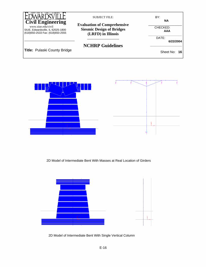
Civil Engineering www.siue.edu/civilSIUE, Edwardsville, IL 62025-1800(618)650-2533 Fax: (618)650-2555
______________________________
Title: Pulaski County Bridge
SUBJECT FILE:
Evaluation of Comprehensive Siesmic Design of Bridges
(LRFD) in Illinois___________________
NCHRP Guidelines
BY:_____________ NA________
____________________CHECKED: _____
AAA_______ ____________________
DATE:__________ 6/22/2004
___________________
Sheet No: 16
2D Model of Intermediate Bent With Masses at Real Location of Girders
2D Model of Intermediate Bent With Single Vertical Column
E-16

Civil Engineering www.siue.edu/civilSIUE, Edwardsville, IL 62025-1800(618)650-2533 Fax: (618)650-2555
______________________________
Title: Pulaski County Bridge
SUBJECT FILE:
Evaluation of Comprehensive Siesmic Design of Bridges
(LRFD) in Illinois___________________
NCHRP Guidelines
BY:_____________ NA________
____________________CHECKED: _____
AAA_______ ____________________
DATE:__________ 6/22/2004
___________________
Sheet No: 17
Without Rotational Mass
M = 2120 k-ft
With Rotational Mass
M = 2780 k-ft
With Masses at Location of Girders
M = 2804 k-ft
E-17

Civil Engineering www.siue.edu/civilSIUE, Edwardsville, IL 62025-1800(618)650-2533 Fax: (618)650-2555
______________________________
Title: Pulaski County Bridge
SUBJECT FILE:
Evaluation of Comprehensive Siesmic Design of Bridges
(LRFD) in Illinois___________________
NCHRP Guidelines
BY:_____________ NA________
____________________CHECKED: _____
AAA_______ ____________________
DATE:__________ 6/22/2004
___________________
Sheet No: 18
kft
Klong_single 2.057 103×=
Klong_single 9612.56⋅:=
Klong_singleVlong_single
∆ long=
KipsVtrans_single 74=
KipsVlong_single 96=
Results from SAP model:
in∆ trans 0.71=
in∆ long 0.56=
Results from L-pile:
58'-4"
S1
S2
4X10 (70" in long and 70" spacing in transverse direction)N 40:=
ksfE29000000 144⋅
1000:=
Use HP 14X117 for the NCHRP design
A=34.4 in^2Ixx=1220 in^4 Zxx=194 in^3Iyy=443 in^4 Zyy=91.4 in^3Depth=14.2 inWidth=14.9 in
Group Pile Stiffness At Fixed Bent:
E-18

Civil Engineering www.siue.edu/civilSIUE, Edwardsville, IL 62025-1800(618)650-2533 Fax: (618)650-2555
______________________________
Title: Pulaski County Bridge
SUBJECT FILE:
Evaluation of Comprehensive Siesmic Design of Bridges
(LRFD) in Illinois___________________
NCHRP Guidelines
BY:_____________ NA________
____________________CHECKED: _____
AAA_______ ____________________
DATE:__________ 6/22/2004
___________________
Sheet No: 19
S22
144N4⋅ .5 70⋅( )2 1.5 70⋅( )2
+⎡⎣ ⎤⎦⋅:=
S18
144.5 70⋅( )2 1.5 70⋅( )2
+ 2.5 70⋅( )2+ 3.5 70⋅( )2
+ 4.5 70⋅( )2+⎡⎣ ⎤⎦⋅:=
kft
Kz 6.651 105×=
Kz Kaxial N⋅:=
kft
Kaxial 1.663 104×=
Kaxial AEL⋅:=
ft2A 0.239=
A34.4144
:=
kft
Ky 5.003 104×=
Ky Ktran_single N⋅:=
Ktran_single 1.251 103×=
Ktran_single 7412.71⋅:=
Ktran_singleVtrans_single
∆ trans=
ftL 60:=
kft
Kx 8.229 104×=
Kx Klong_single N⋅:=
E-19

Civil Engineering www.siue.edu/civilSIUE, Edwardsville, IL 62025-1800(618)650-2533 Fax: (618)650-2555
______________________________
Title: Pulaski County Bridge
SUBJECT FILE:
Evaluation of Comprehensive Siesmic Design of Bridges
(LRFD) in Illinois___________________
NCHRP Guidelines
BY:_____________ NA________
____________________CHECKED: _____
AAA_______ ____________________
DATE:__________ 6/22/2004
___________________
Sheet No: 20
kipsV 1109:=
No of piles usedN 40=
Ultimate axial capacity of pilekipsPcap 464.4=
A is area of cross-section of single pilePcap A 1.5⋅ 9⋅ 144⋅:=
Axial capacity (IDOT Bridge Manual 3.8.1) = 9000 psi
Total DL = 1109 kips
ft Kips−
radKrz 2.523 107
×=
ft Kips−
radKry 2.829 107
×=
ft Kips−
radKrx 1.867 108
×=
kft
Kz 6.651 105×=
kft
Ky 5.003 104×=
kft
Kx 8.229 104×=
Krz Klong_single S1⋅ Ktran_single S2⋅+( ):=
Kry Kaxial S2⋅:=
Krx Kaxial S1⋅:=
E-20

Civil Engineering www.siue.edu/civilSIUE, Edwardsville, IL 62025-1800(618)650-2533 Fax: (618)650-2555
______________________________
Title: Pulaski County Bridge
SUBJECT FILE:
Evaluation of Comprehensive Siesmic Design of Bridges
(LRFD) in Illinois___________________
NCHRP Guidelines
BY:_____________ NA________
____________________CHECKED: _____
AAA_______ ____________________
DATE:__________ 6/22/2004
___________________
Sheet No: 21
for steel pileP10.85 50⋅ 34.4⋅
89
M150 194⋅
M250 91.4⋅
+⎛⎜⎝
⎞⎠
⋅+ 0.944= < 1 OK
EQ in transverse direction
Results from SAP :
Mlong 18646:= k ft− Mtran 38811:= k ft−
P2VN
Mlong1.5 75⋅
12S2⋅+ Mtran
4.5 75⋅
12S1⋅+:=
P2 227.676= kips Pcap< OK
Results from L-pile:
DisL .15:= in M3 2230:= k in−
M4 3055:= k in−DisT .57:= in
Results from SAP :
Mlong 46161:= k ft− Mtran 15526:= k ft−
P1VN
Mlong1.5 75⋅
12 S2⋅⋅+ Mtran
4.5 75⋅
12 S1⋅⋅+:=
P1 320.969= kips
P1 < Pcap Ok
Results from L-pile:
DisL .39:= in M1 4080:= k in−
DisT .23:= in M2 1800:= k in−
Compressive Resistance (Combined axial compression and flexure)
f y 50.ksi=
E-21

Civil Engineering www.siue.edu/civilSIUE, Edwardsville, IL 62025-1800(618)650-2533 Fax: (618)650-2555
______________________________
Title: Pulaski County Bridge
SUBJECT FILE:
Evaluation of Comprehensive Siesmic Design of Bridges
(LRFD) in Illinois___________________
NCHRP Guidelines
BY:_____________ NA________
____________________CHECKED: _____
AAA_______ ____________________
DATE:__________ 6/22/2004
___________________
Sheet No: 22
Kz Kaxial N⋅:=
kft
Kaxial 1.663 104×=
Kaxial AEL⋅:=
ft2A 0.239=
A34.4144
:=
kft
Ky 3.002 104×=
Ky Ktran_single N⋅:=
Ktran_single 1.251 103×=
ftL 60:=
kft
Kx 4.937 104×=
Kx Klong_single N⋅:=
560"
S1
S2
kft
Klong_single 2.057 103×=
3X8 (70" spacing in both direction)N 24:=
Spring Stiffness at Expansion Bent
AASHTO LRFD6.9.2.2 2−( )<1 OKP2
0.85 50⋅ 34.4⋅
89
M350 194⋅
M450 91.4⋅
+⎛⎜⎝
⎞⎠
⋅+ 0.954=
E-22
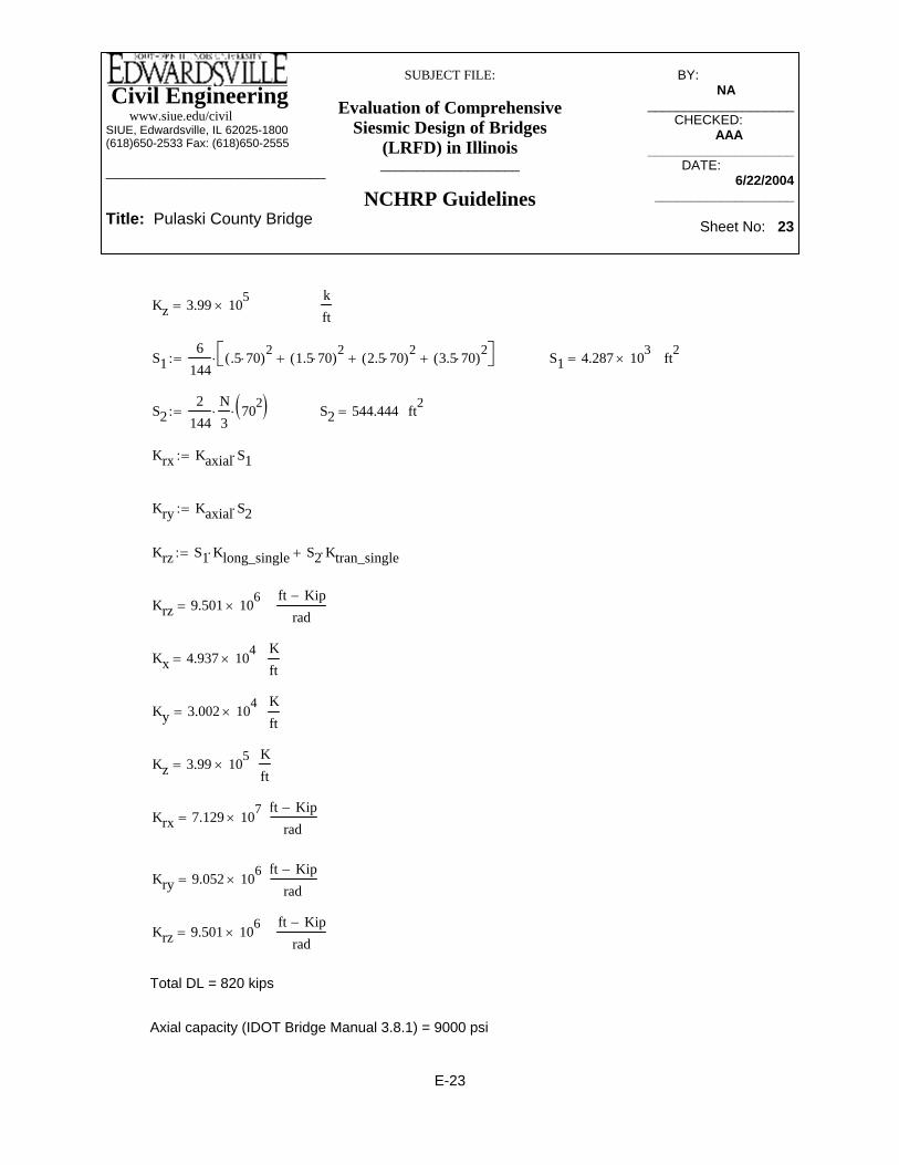
Civil Engineering www.siue.edu/civilSIUE, Edwardsville, IL 62025-1800(618)650-2533 Fax: (618)650-2555
______________________________
Title: Pulaski County Bridge
SUBJECT FILE:
Evaluation of Comprehensive Siesmic Design of Bridges
(LRFD) in Illinois___________________
NCHRP Guidelines
BY:_____________ NA________
____________________CHECKED: _____
AAA_______ ____________________
DATE:__________ 6/22/2004
___________________
Sheet No: 23
Axial capacity (IDOT Bridge Manual 3.8.1) = 9000 psi
Total DL = 820 kips
ft Kip−
radKrz 9.501 106
×=
ft Kip−
radKry 9.052 106
×=
ft Kip−
radKrx 7.129 107
×=
Kft
Kz 3.99 105×=
Kft
Ky 3.002 104×=
Kft
Kx 4.937 104×=
ft Kip−
radKrz 9.501 106
×=
Krz S1 Klong_single⋅ S2 Ktran_single⋅+:=
Kry Kaxial S2⋅:=
Krx Kaxial S1⋅:=
ft2S2 544.444=S22
144N3⋅ 702( )⋅:=
ft2S1 4.287 103×=S1
6144
.5 70⋅( )2 1.5 70⋅( )2+ 2.5 70⋅( )2
+ 3.5 70⋅( )2+⎡⎣ ⎤⎦⋅:=
kft
Kz 3.99 105×=
E-23
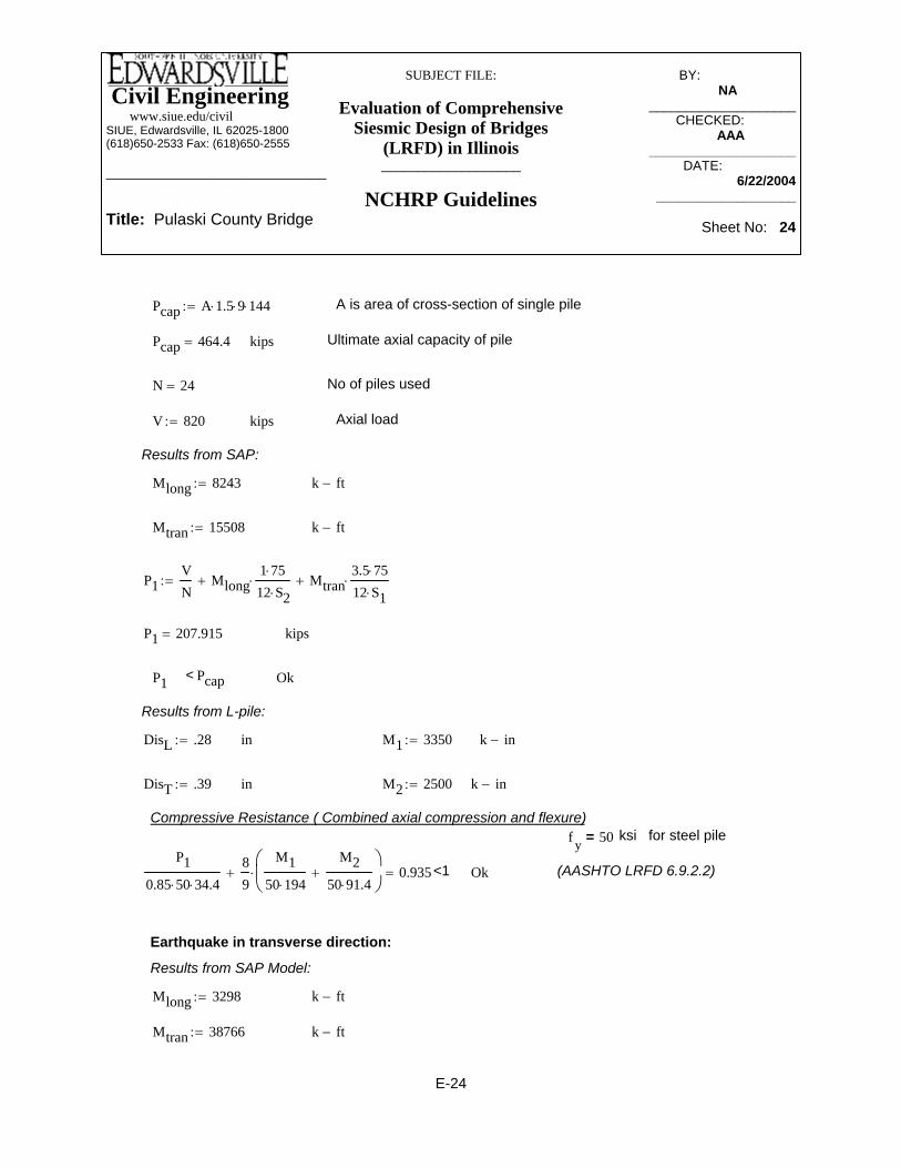
Civil Engineering www.siue.edu/civilSIUE, Edwardsville, IL 62025-1800(618)650-2533 Fax: (618)650-2555
______________________________
Title: Pulaski County Bridge
SUBJECT FILE:
Evaluation of Comprehensive Siesmic Design of Bridges
(LRFD) in Illinois___________________
NCHRP Guidelines
BY:_____________ NA________
____________________CHECKED: _____
AAA_______ ____________________
DATE:__________ 6/22/2004
___________________
Sheet No: 24
DisL .28:= in M1 3350:= k in−
DisT .39:= in M2 2500:= k in−
Compressive Resistance ( Combined axial compression and flexure)f y 50= ksi for steel pile
P10.85 50⋅ 34.4⋅
89
M150 194⋅
M250 91.4⋅
+⎛⎜⎝
⎞⎠
⋅+ 0.935= <1 Ok (AASHTO LRFD 6.9.2.2)
Earthquake in transverse direction:
Results from SAP Model:
Mlong 3298:= k ft−
Mtran 38766:= k ft−
Pcap A 1.5⋅ 9⋅ 144⋅:= A is area of cross-section of single pile
Pcap 464.4= kips Ultimate axial capacity of pile
N 24= No of piles used
V 820:= kips Axial load
Results from SAP:
Mlong 8243:= k ft−
Mtran 15508:= k ft−
P1VN
Mlong1 75⋅
12 S2⋅⋅+ Mtran
3.5 75⋅
12 S1⋅⋅+:=
P1 207.915= kips
P1 < Pcap Ok
Results from L-pile:
E-24

Civil Engineering www.siue.edu/civilSIUE, Edwardsville, IL 62025-1800(618)650-2533 Fax: (618)650-2555
______________________________
Title: Pulaski County Bridge
SUBJECT FILE:
Evaluation of Comprehensive Siesmic Design of Bridges
(LRFD) in Illinois___________________
NCHRP Guidelines
BY:_____________ NA________
____________________CHECKED: _____
AAA_______ ____________________
DATE:__________ 6/22/2004
___________________
Sheet No: 25
Ok<1P2
0.85 50⋅ 34.4⋅
89
M350 194⋅
M450 91.4⋅
+⎛⎜⎝
⎞⎠
⋅+ 0.998=
Compressive Resistance ( Combined axial compression and flexure)
inDisT .75:=k in−M4 3380:=
k in−M3 1700:=inDisL .11:=
Results from L-pile:
< Pcap OKkipsP2 269.812=
P2VN
Mlong1 75⋅
12S2⋅+ Mtran
3.5 75⋅
12S1⋅+:=
E-25
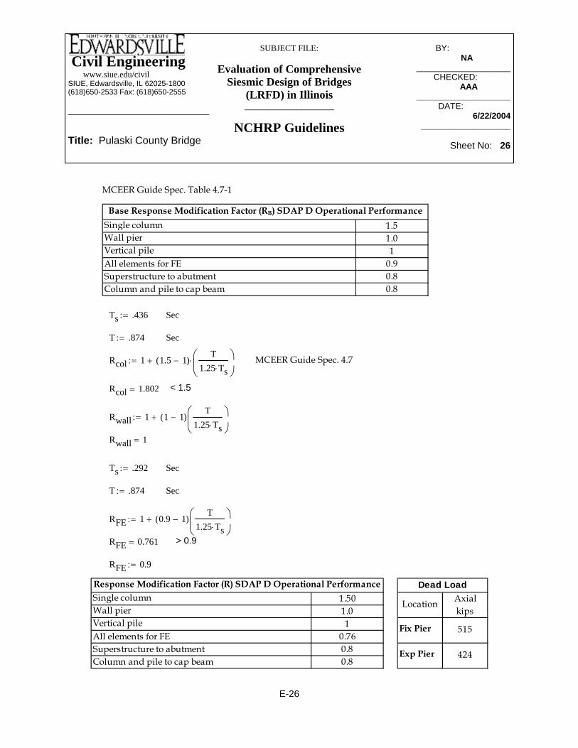
Civil Engineering www.siue.edu/civilSIUE, Edwardsville, IL 62025-1800(618)650-2533 Fax: (618)650-2555
______________________________
Title: Pulaski County Bridge
SUBJECT FILE:
Evaluation of Comprehensive Siesmic Design of Bridges
(LRFD) in Illinois___________________
NCHRP Guidelines
BY:_____________ NA________
____________________CHECKED: _____
AAA_______ ____________________
DATE:__________ 6/22/2004
___________________
Sheet No: 26
Axialkips
Fix Pier
Exp Pier
Dead Load
Location
424
515
1.501.01
0.760.80.8
Superstructure to abutmentColumn and pile to cap beam
Response Modification Factor (R) SDAP D Operational PerformanceSingle column
Vertical pileAll elements for FE
Wall pier
RFE 0.9:=
> 0.9RFE 0.761=
RFE 1 0.9 1−( )T
1.25 Ts⋅⎛⎜⎝
⎞⎠
+:=
SecT .874:=
SecTs .292:=
Rwall 1=
Rwall 1 1 1−( )T
1.25 Ts⋅⎛⎜⎝
⎞⎠
+:=
< 1.5Rcol 1.802=
MCEER Guide Spec. 4.7Rcol 1 1.5 1−( )T
1.25 Ts⋅⎛⎜⎝
⎞⎠
⋅+:=
SecT .874:=
SecTs .436:=
1.51.01
0.90.80.8
Superstructure to abutmentColumn and pile to cap beam
Base Response Modification Factor (RB) SDAP D Operational PerformanceSingle column
Vertical pileAll elements for FE
Wall pier
MCEER Guide Spec. Table 4.7-1
E-26

Civil Engineering www.siue.edu/civilSIUE, Edwardsville, IL 62025-1800(618)650-2533 Fax: (618)650-2555
______________________________
Title: Pulaski County Bridge
SUBJECT FILE:
Evaluation of Comprehensive Siesmic Design of Bridges
(LRFD) in Illinois___________________
NCHRP Guidelines
BY:_____________ NA________
____________________CHECKED: _____
AAA_______ ____________________
DATE:__________ 6/22/2004
___________________
Sheet No: 27
Shear 3 Moment 2 Moment 3 Axialkips kip-ft kip-ft kips
Top 24709 0Bottom 35753 0
Top 11777 0Bottom 33204 0
0
0Exp Pier
Support / Location
MCE Forces & Moments - EQtrans
1139
Transverse
Fix Pier
1510
Shear 2 Moment 2 Moment 3 Axialkips kip-ft kip-ft kips
Top 0 0Bottom 0 40481
Top 0 0Bottom 0 6494
Longitudinal
1854 0
462 68
Fix Pier
Exp Pier
Forces & Moments - EQlong
Support / Location
MCE
Shear 2 Shear 3 Moment 3 Moment 2 Axial Shear 3 Shear 2 Moment 2 Moment 3 Axialkips kips kip-ft kip-ft kips kips kips kip-ft kip-ft kips
Top 0 24709 9884 0Bottom 16192 35753 14301 40481
Top 0 11777 4711 0Bottom 2598 33204 13282 6494
Exp Pier
Fix Pier
MCE
Support / Location
100% + 40% Forces & Moments - EQ
742
185 46227 604
0 0
68
456 1854
Transverse
1139
1510
Longitudinal
Shear 2 Shear 3 Moment 3 Moment 2 Axial Shear 3 Shear 2 Moment 2 Moment 3 Axialkips kips kip-ft kip-ft kips kips kips kip-ft kip-ft kips
Top 0 24709 9884 0Bottom 10795 35753 14301 26987
Top 0 11777 4711 0Bottom 1732 33204 13282 4329
Fix Pier
Exp Pier
Support / Location
MCE Transverse
1236
123
1139
1510 604
0
308
Factored Forces & Moments - EQ by RLongitudinal
456 0
18
494
45
E-27

Civil Engineering www.siue.edu/civilSIUE, Edwardsville, IL 62025-1800(618)650-2533 Fax: (618)650-2555
______________________________
Title: Pulaski County Bridge
SUBJECT FILE:
Evaluation of Comprehensive Siesmic Design of Bridges
(LRFD) in Illinois___________________
NCHRP Guidelines
BY:_____________ NA________
____________________CHECKED: _____
AAA_______ ____________________
DATE:__________ 6/22/2004
___________________
Sheet No: 28
Shear 2 Shear 3 Moment 3 Moment 2 Axial Shear 3 Shear 2 Moment 2Moment 3 Axialkips kips kip-ft kip-ft kips kips kips kip-ft kip-ft kips
Top 0 24709 9884 0Bottom 10795 35753 14301 26987
Top 0 11777 4711 0Bottom 1732 33204 13282 4329
Exp Pier 1510
Fix Pier
MCE
Support / Location
123
Final Design Forces & Moments (EQ + DL)Transverse
494 1139 570
604
570
Longitudinal
515
456 1236
488 308
E-28

Civil Engineering www.siue.edu/civilSIUE, Edwardsville, IL 62025-1800(618)650-2533 Fax: (618)650-2555
______________________________
Title: Pulaski County Bridge
SUBJECT FILE:
Evaluation of Comprehensive Siesmic Design of Bridges
(LRFD) in Illinois___________________
NCHRP Guidelines
BY:_____________ NA________
____________________CHECKED: _____
AAA_______ ____________________
DATE:__________ 6/22/2004
___________________
Sheet No: 29
Interaction diagram for the fixed bent. As the thickness of the wall was inadequate forthe maximum moment, the thickness of the wall has been increased to 4'
E-29

Civil Engineering www.siue.edu/civilSIUE, Edwardsville, IL 62025-1800(618)650-2533 Fax: (618)650-2555
______________________________
Title: Pulaski County Bridge
SUBJECT FILE:
Evaluation of Comprehensive Siesmic Design of Bridges
(LRFD) in Illinois___________________
NCHRP Guidelines
BY:_____________ NA________
____________________CHECKED: _____
AAA_______ ____________________
DATE:__________ 6/22/2004
___________________
Sheet No: 30
Maximum moment at the bottom of pier based on 2.5' thick wall.
The finite element model was run for the 4' thick pier. In this analysis moment has increased by 100% by using 48" thick wall and the pier can not be design for this moment. So all of three pier will be considered fixed in longitudinal direction of thebridge.
E-30

Civil Engineering www.siue.edu/civilSIUE, Edwardsville, IL 62025-1800(618)650-2533 Fax: (618)650-2555
______________________________
Title: Pulaski County Bridge
SUBJECT FILE:
Evaluation of Comprehensive Siesmic Design of Bridges
(LRFD) in Illinois___________________
NCHRP Guidelines
BY:_____________ NA________
____________________CHECKED: _____
AAA_______ ____________________
DATE:__________ 6/22/2004
___________________
Sheet No: 31
Ktran_singleVtrans_single
∆ trans=
ftL 60:=
kft
Kx 1.48 105×=
Kx Klong_single N⋅:=
kft
Klong_single 3.7 103×=
Klong_single 7412.24⋅:=
Klong_singleVlong_single
∆ long=
in∆ trans 0.66=
in∆ long 0.24=
Results from L-pile:
KipsVtrans_single 75=
KipsVlong_single 74=
Results from SAP model:
4X10 (70" in long and 70" spacing in transverse direction)N 40:=
ksfE 4.176 106×=
E 290000001441000⋅:=
Group Pile Stiffness (All Bents Fixed)
E-31

Civil Engineering www.siue.edu/civilSIUE, Edwardsville, IL 62025-1800(618)650-2533 Fax: (618)650-2555
______________________________
Title: Pulaski County Bridge
SUBJECT FILE:
Evaluation of Comprehensive Siesmic Design of Bridges
(LRFD) in Illinois___________________
NCHRP Guidelines
BY:_____________ NA________
____________________CHECKED: _____
AAA_______ ____________________
DATE:__________ 6/22/2004
___________________
Sheet No: 32
Krz Klong_single S1⋅ Ktran_single S2⋅+( ):=
Kry Kaxial S2⋅:=
Krx Kaxial S1⋅:=
S22
144N4⋅ .5 70⋅( )2 1.5 70⋅( )2
+⎡⎣ ⎤⎦⋅:=
S16
144.5 70⋅( )2 1.5 70⋅( )2
+ 2.5 70⋅( )2+ 3.5 70⋅( )2
+ 4.5 70⋅( )2+⎡⎣ ⎤⎦⋅:=
kft
Kz 6.651 105×=
Kz Kaxial N⋅:=
kft
Kaxial 1.663 104×=
Kaxial AEL⋅:=
ft2A 0.239=
A34.4144
:=
kft
Ky 5.455 104×=
58'-4"
S1
S2
Ky Ktran_single N⋅:=
Ktran_single 1.364 103×=
Ktran_single 7512.66⋅:=
E-32

Civil Engineering www.siue.edu/civilSIUE, Edwardsville, IL 62025-1800(618)650-2533 Fax: (618)650-2555
______________________________
Title: Pulaski County Bridge
SUBJECT FILE:
Evaluation of Comprehensive Siesmic Design of Bridges
(LRFD) in Illinois___________________
NCHRP Guidelines
BY:_____________ NA________
____________________CHECKED: _____
AAA_______ ____________________
DATE:__________ 6/22/2004
___________________
Sheet No: 33
kips Ultimate axial capacity of pile
N 40= No of piles used
V 1065:= kips
Results from SAP:
Mlong 31836:= k ft−
Mtran 17848:= k ft−
P1VN
Mlong1.5 70⋅
12 S2⋅⋅+ Mtran
4.5 70⋅
12 S1⋅⋅+:=
P1 245.983= kips
P1 < Pcap Ok
kftKx 1.48 105
×=
kftKy 5.455 104
×=
kftKz 6.651 105
×=
k ft−
radKrx 1.4 108×=
k ft−
radKry 2.829 107×=
Krz 3.348 107×=
k ft−
rad
Total DL = 1065 kips
Axial capacity (IDOT Bridge Manual 3.8.1) = 9000 psi
Pcap A 1.5⋅ 9⋅ 144⋅:= A is area of cross-section of single pile
Pcap 464.4=
E-33
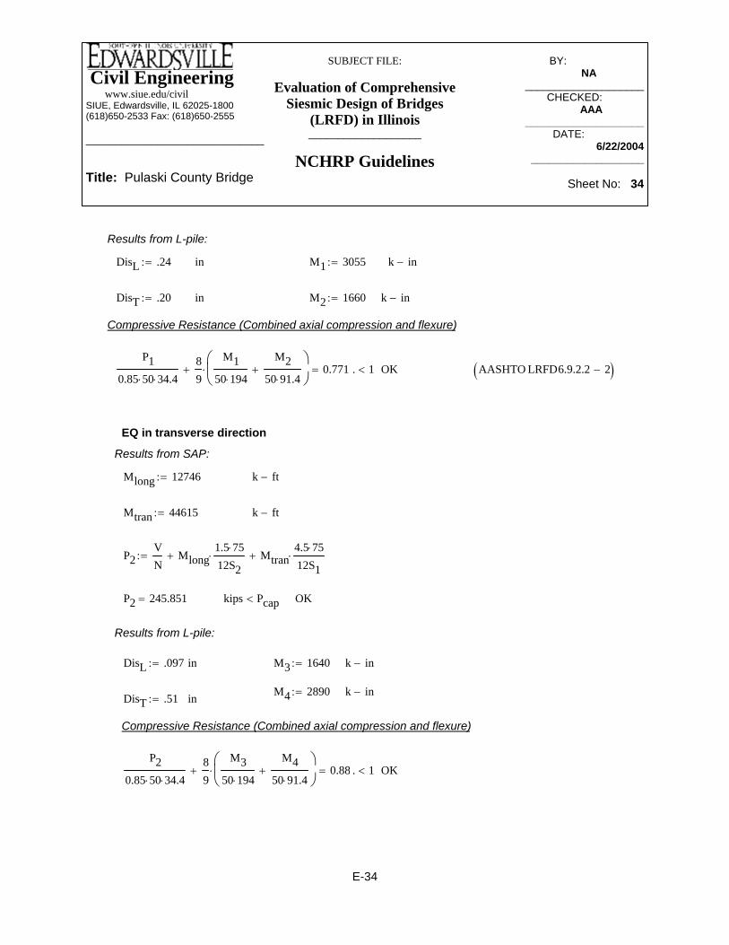
Civil Engineering www.siue.edu/civilSIUE, Edwardsville, IL 62025-1800(618)650-2533 Fax: (618)650-2555
______________________________
Title: Pulaski County Bridge
SUBJECT FILE:
Evaluation of Comprehensive Siesmic Design of Bridges
(LRFD) in Illinois___________________
NCHRP Guidelines
BY:_____________ NA________
____________________CHECKED: _____
AAA_______ ____________________
DATE:__________ 6/22/2004
___________________
Sheet No: 34
k ft−
P2VN
Mlong1.5 75⋅
12S2⋅+ Mtran
4.5 75⋅
12S1⋅+:=
P2 245.851= kips Pcap< OK
Results from L-pile:
DisL .097:= in M3 1640:= k in−
M4 2890:= k in−DisT .51:= in
Compressive Resistance (Combined axial compression and flexure)
P20.85 50⋅ 34.4⋅
89
M350 194⋅
M450 91.4⋅
+⎛⎜⎝
⎞⎠
⋅+ 0.881= . 1< OK
Results from L-pile:
DisL .24:= in M1 3055:= k in−
DisT .20:= in M2 1660:= k in−
Compressive Resistance (Combined axial compression and flexure)
P10.85 50⋅ 34.4⋅
89
M150 194⋅
M250 91.4⋅
+⎛⎜⎝
⎞⎠
⋅+ 0.771= . 1< OK AASHTO LRFD6.9.2.2 2−( )
EQ in transverse direction
Results from SAP:
Mlong 12746:= k ft−
Mtran 44615:=
E-34

Civil Engineering www.siue.edu/civilSIUE, Edwardsville, IL 62025-1800(618)650-2533 Fax: (618)650-2555
______________________________
Title: Pulaski County Bridge
SUBJECT FILE:
Evaluation of Comprehensive Siesmic Design of Bridges
(LRFD) in Illinois___________________
NCHRP Guidelines
BY:_____________ NA________
____________________CHECKED: _____
AAA_______ ____________________
DATE:__________ 6/22/2004
___________________
Sheet No: 35
1.501.01
0.90.80.8
Superstructure to abutmentColumn and pile to cap beam
Response Modification Factor (R) SDAP D Operational PerformanceSingle column
Vertical pileAll elements for FE
Wall pier
RFE 0.9:=
> 0.9RFE 0.84=
RFE 1 0.9 1−( )T
1.25 Ts⋅⎛⎜⎝
⎞⎠
+:=
Rwall 1=
Rwall 1 1 1−( )T
1.25 Ts⋅⎛⎜⎝
⎞⎠
+:=
< 1.5Rcol 1.802=
MCEER Guide Spec. 4.7Rcol 1 1.5 1−( )T
1.25 Ts⋅⎛⎜⎝
⎞⎠
⋅+:=
SecT .8738:=
SecTs 0.436:=
1.51.01
0.90.80.8
Superstructure to abutmentColumn and pile to cap beam
Base Response Modification Factor (RB) SDAP D Operational PerformanceSingle column
Vertical pileAll elements for FE
Wall pier
MCEER Guide Spec. Table 4.7-1
E-35

Civil Engineering www.siue.edu/civilSIUE, Edwardsville, IL 62025-1800(618)650-2533 Fax: (618)650-2555
______________________________
Title: Pulaski County Bridge
SUBJECT FILE:
Evaluation of Comprehensive Siesmic Design of Bridges
(LRFD) in Illinois___________________
NCHRP Guidelines
BY:_____________ NA________
____________________CHECKED: _____
AAA_______ ____________________
DATE:__________ 6/22/2004
___________________
Sheet No: 36
Shear 3 Moment 2 Moment 3 Axialkips kip-ft kip-ft kips
Top 28687 0Bottom 41430 0
Top 16116 0Bottom 39190 0
0
0Pier 1&3
Support / Location
MCE Forces & Moments - EQtrans
1199
Transverse
Pier 2
1651
Axialkips
470
570Pier 2
Pier 1&3
Dead Load
Location
Shear 2 Moment 2 Moment 3 Axialkips kip-ft kip-ft kips
Top 0 0Bottom 0 27654
Top 0 0Bottom 0 32521
Longitudinal
1342 0
1758 184
Pier 2
Pier 1&3
Forces & Moments - EQlong
Support / Location
MCE
Shear 2 Shear 3 Moment 3 Moment 2 Axial Shear 3 Shear 2 Moment 2 Moment 3 Axialkips kips kip-ft kip-ft kips kips kips kip-ft kip-ft kips
Top 0 28687 11475 0Bottom 11062 41430 16572 27654
Top 0 16116 6446 0Bottom 13008 39190 15676 32521
Longitudinal
1199
1651 184
480 1342
Transverse
0 0
703 175874 660Pier 1&3
Pier 2
MCE
Support / Location
100% + 40% Forces & Moments - EQ
537
Shear 2 Shear 3 Moment 3 Moment 2 Axial Shear 3 Shear 2 Moment 2 Moment 3 Axialkips kips kip-ft kip-ft kips kips kips kip-ft kip-ft kips
Top 0 28687 11475 0Bottom 7374 41430 16572 18436
Top 0 16116 6446 0Bottom 8672 39190 15676 21681 123
Factored Forces & Moments - EQ by RLongitudinal
480 0
49
358 895
469
1199
1651 660
0
1172
Support / Location
MCE Transverse
Pier 1&3
Pier 2
Shear 2 Shear 3 Moment 3 Moment 2 Axial Shear 3 Shear 2 Moment 2Moment 3 Axialkips kips kip-ft kip-ft kips kips kips kip-ft kip-ft kips
Top 0 28687 11475 0Bottom 7374 41430 16572 18436
Top 0 16116 6446 0Bottom 8672 39190 15676 21681
Pier 1&3 1651
Pier 2
MCE
Support / Location
469
Final Design Forces & Moments (EQ + DL)Transverse
358 1199 570
660
570
Longitudinal
593
480 895
519 1172
E-36

Civil Engineering www.siue.edu/civilSIUE, Edwardsville, IL 62025-1800(618)650-2533 Fax: (618)650-2555
______________________________
Title: Pulaski County Bridge
SUBJECT FILE:
Evaluation of Comprehensive Siesmic Design of Bridges
(LRFD) in Illinois___________________
NCHRP Guidelines
BY:_____________ NA________
____________________CHECKED: _____
AAA_______ ____________________
DATE:__________ 6/22/2004
___________________
Sheet No: 37
Shear 3 Moment 2 Moment 3 Axial Kips Kip-ft Kip-ft Kips
Top 393 0Bottom 703 0Top 245 0Bottom 359 0
Pier 1&3
Pier 2 30
17
0
0
FEForces & Moments- EQtrans
Transverse
Support/Location
Shear 2 Moment 2 Moment 3 Axial Kips Kip-ft Kip-ft Kips
Top 0 0Bottom 0 753Top 0 0Bottom 0 942
FEForces & Moments- EQlong
Longitudinal
Support/Location
Pier 2
Pier 1&3
36
51
0
4
Shear 2 Shear 3 Moment 2 Moment 3 Axial Shear 2 Shear 3 Moment 2 Moment 3 Axialkips kips kip-ft kip-ft kips kips kips kip-ft kip-ft kips
Top 393 0 157 0Bottom 703 301 281 753
Top 245 0 98 0Bottom 359 377 144 942
FE 100% + 40% Forces & Moments - EQTransverse Longitudinal
Support / Location
Pier 2 14 30 0 36 12 0
Pier 1&3 21 17 2 51 7 4
Shear 2 Shear 3 Moment 2 Moment 3 Axial Shear 2 Shear 3 Moment 2 Moment 3 Axialkips kips kip-ft kip-ft kips kips kips kip-ft kip-ft kips
Top 437 0 175 0Bottom 781 335 312 837
Top 272 0 109 0Bottom 399 419 160 1047
0 40 14 0
57
Support / Location
Pier 2 16 34
FE Factored Forces & Moments - EQ/RTransverse Longitudinal
8 5Pier 1&3 24 19 2
Shear 2 Shear 3 Moment 2 Moment 3 Axial Shear 2 Shear 3 Moment 2 Moment 3 Axialkips kips kip-ft kip-ft kips kips kips kip-ft kip-ft kips
Top 437 0 175 0Bottom 781 335 312 837
Top 272 0 109 0Bottom 399 419 160 1047
FE Final Design Forces & Moments - (EQ/R+DL)Transverse Longitudinal
Support / Location
Pier 2 16 34 570 40 14 570
57 8 475Pier 1&3 24 19 472
E-37

Civil Engineering www.siue.edu/civilSIUE, Edwardsville, IL 62025-1800(618)650-2533 Fax: (618)650-2555
______________________________
Title: Pulaski County Bridge
SUBJECT FILE:
Evaluation of Comprehensive Siesmic Design of Bridges
(LRFD) in Illinois___________________
NCHRP Guidelines
BY:_____________ NA________
____________________CHECKED: _____
AAA_______ ____________________
DATE:__________ 6/22/2004
___________________
Sheet No: 38
Therefore, MCE design forces govern.
E-38

Civil Engineering www.siue.edu/civilSIUE, Edwardsville, IL 62025-1800(618)650-2533 Fax: (618)650-2555
______________________________
Title: Pulaski County Bridge
SUBJECT FILE:
Evaluation of Comprehensive Siesmic Design of Bridges
(LRFD) in Illinois___________________
NCHRP Guidelines
BY:_____________ NA________
____________________CHECKED: _____
AAA_______ ____________________
DATE:__________ 6/22/2004
___________________
Sheet No: 39
Shear 3 Moment 2 Moment 3 Axialkips kip-ft kip-ft kips
Top 28687 0Bottom 37284 0
Top 16116 0Bottom 31133 0
Pier 1&3
Support / Location
MCE Forces & Moments - EQtrans
1146
Transverse
Pier 2
1601
0
0
Forces at 5.5' from the bottomof the pier. Reinforcement dueto this design will be used for the upper part of the piers
Axialkips
Pier 2
Pier 1&3
Dead Load
Location
421
519Shear 2 Moment 2 Moment 3 Axial
kips kip-ft kip-ft kipsTop 0 0
Bottom 0 20367Top 0 0
Bottom 0 22915
Pier 2
Pier 1&3
Forces & Moments - EQlong
Support / Location
MCELongitudinal
1312 0
1745 184
Shear 2 Shear 3 Moment 3 Moment 2 Axial Shear 3 Shear 2 Moment 2 Moment 3 Axialkips kips kip-ft kip-ft kips kips kips kip-ft kip-ft kips
Top 0 28687 11475 0Bottom 8147 37284 14914 20367
Top 0 16116 6446 0Bottom 9166 31133 12453 22915
Longitudinal
1146
1601 184
458 1312
Transverse
0 0
698 174574 640Pier 1&3
Pier 2
MCE
Support / Location
100% + 40% Forces & Moments - EQ
525
Shear 2 Shear 3 Moment 3 Moment 2 Axial Shear 3 Shear 2 Moment 2 Moment 3 Axialkips kips kip-ft kip-ft kips kips kips kip-ft kip-ft kips
Top 0 28687 11475 0Bottom 5431 37284 14914 13578
Top 0 16116 6446 0Bottom 6111 31133 12453 15277
Pier 2
Pier 1&3
Support / Location
MCE Transverse
875
465
1146
1601 640
0
1163
Factored Forces & Moments - EQ by RLongitudinal
458 0
49
350
123
Shear 2 Shear 3 Moment 3 Moment 2 Axial Shear 3 Shear 2 Moment 2Moment 3 Axialkips kips kip-ft kip-ft kips kips kips kip-ft kip-ft kips
Top 0 28687 11475 0Bottom 5431 37284 14914 13578
Top 0 16116 6446 0Bottom 6111 31133 12453 15277
Pier 1&3 1601
Pier 2
MCE
Support / Location
465
Final Design Forces & Moments (EQ + DL)Transverse
350 1146 519
640
519
Longitudinal
544
458 875
470 1163
E-39

Civil Engineering www.siue.edu/civilSIUE, Edwardsville, IL 62025-1800(618)650-2533 Fax: (618)650-2555
______________________________
Title: Pulaski County Bridge
SUBJECT FILE:
Evaluation of Comprehensive Siesmic Design of Bridges
(LRFD) in Illinois___________________
NCHRP Guidelines
BY:_____________ NA________
____________________CHECKED: _____
AAA_______ ____________________
DATE:__________ 6/22/2004
___________________
Sheet No: 40
E-40

Civil Engineering www.siue.edu/civilSIUE, Edwardsville, IL 62025-1800(618)650-2533 Fax: (618)650-2555
______________________________
Title: Pulaski County Bridge
SUBJECT FILE:
Evaluation of Comprehensive Siesmic Design of Bridges
(LRFD) in Illinois___________________
NCHRP Guidelines
BY:_____________ NA________
____________________CHECKED: _____
AAA_______ ____________________
DATE:__________ 6/22/2004
___________________
Sheet No: 41
Controls but last check should be done after design in1.5 0.08 M⋅12V
⋅ 4400 εy⋅ db⋅+⎛⎜⎝
⎞⎠
48.941=
kV 1199:=
k ft−M 24711:=
for #11indb 1.41:=
εy 0.00207:=
4-
in18
3-
in16
H⋅ 42.708=
inH 256.25:=
2-
inD 48:=
inD h 3−:=
1-
thickness of the wallinh 48:=
Plastic hinge zone length (this length will modify after the reinforcement design)MCEER Guide Spec. 4.9.1
Transverse Reinforcement DesignFor the Pier 2
E-41

Civil Engineering www.siue.edu/civilSIUE, Edwardsville, IL 62025-1800(618)650-2533 Fax: (618)650-2555
______________________________
Title: Pulaski County Bridge
SUBJECT FILE:
Evaluation of Comprehensive Siesmic Design of Bridges
(LRFD) in Illinois___________________
NCHRP Guidelines
BY:_____________ NA________
____________________CHECKED: _____
AAA_______ ____________________
DATE:__________ 6/22/2004
___________________
Sheet No: 42
Axial earthquake force
MtopL 0:= k ft−
MbotL 24711:= k ft−
OS 1.5:= Over strength factor
Mp_topL OS MtopL⋅:=
Mp_topL 0= k ft−
Mp_botL OS MbotL⋅:=
Mp_botL 3.707 104×= k ft−
VuLMp_topL Mp_botL+( ) 12⋅
L R⋅:=
VuL 2.17 103×= kips
Vu_analysisVR
:= kips
Wall pier transverse reinforcementMethod 2: Explicit Approach(Guide Spec 8.8.2.3)Pier 2192"X48" (3.32% steel, 86#11 in two layers at top and 12#11 each side)
N 196:= number of longitudinal reinforcement
R 0.8:= R-factor for joint (table 3.1-2)
L H:= in Height of the pier
Ab 1.56:= in2 Area of rebars for longitudinal rebar
For longitudinal case which is govern for this bridge. For transverse direction, value of 2 is used for the case of fixed - fixed.Λ 1:= fixed - free
Pd 570:= kips Axial dead load in the pier
Pe 0:= kips
E-42

Civil Engineering www.siue.edu/civilSIUE, Edwardsville, IL 62025-1800(618)650-2533 Fax: (618)650-2555
______________________________
Title: Pulaski County Bridge
SUBJECT FILE:
Evaluation of Comprehensive Siesmic Design of Bridges
(LRFD) in Illinois___________________
NCHRP Guidelines
BY:_____________ NA________
____________________CHECKED: _____
AAA_______ ____________________
DATE:__________ 6/22/2004
___________________
Sheet No: 43
Width of the column core
Dp 43= in
DpL
0.168=
VpΛ
2Pe⋅
DpL
⋅:=
Vp 0= kips Contribution due to arch action
φ 0.90:= For shear
Vu 2.17 103×= kips
VsVuφ
Vp Vc+( )−:=
Vs 2.084 103×= kips
Kshape .5:= For wall in weak axis (MCEER 8.8.2.3)
Vu max VuL Vu_analysis,( ):=
Vu 2.17 103×= kips
fc 3500:= psi
bw 192:= in
d D:= in
h 48= in
Vc .6 fc( )⎡⎣ ⎤⎦ bw⋅d
1000⋅:= Shear resistance in the end regions (plastic hinge zone)
Vc 327.136= kips
L 256.25= in
Dp h 5−:=
E-43

Civil Engineering www.siue.edu/civilSIUE, Edwardsville, IL 62025-1800(618)650-2533 Fax: (618)650-2555
______________________________
Title: Pulaski County Bridge
SUBJECT FILE:
Evaluation of Comprehensive Siesmic Design of Bridges
(LRFD) in Illinois___________________
NCHRP Guidelines
BY:_____________ NA________
____________________CHECKED: _____
AAA_______ ____________________
DATE:__________ 6/22/2004
___________________
Sheet No: 44
legs 10:= Number of legs
ρv_pr legsAshbw s⋅⋅:=
ρv_pr 2.604 10 3−×=
Ac bw 6−( ) h 6−( )⋅:= Area of column core concreteAg bw h⋅:=
Ac 7.812 103×= in2
Ag 9.216 103×= in2
tanθ 1.6 ρv_pr⋅Av
Λ ρt⋅ Ag⋅⋅
⎛⎜⎝
⎞
⎠
.25
:=
tanθ 0.595=
Dpp h 4−:= Width of the perimeter transverse direction
Avs sVs
fyh Dpp⋅⋅ tanθ⋅:=
Avslegs
0.188= in2 < Ash OK
fyh 60:= ksi For the transverse and longitudinal steel
fsu 1.5 fyh⋅:= Ultimate tensile stress of the longitudinal reinforcement
fsu 90= ksi
Av bw d⋅:= Shear area
Av 9.216 103×= in2
ρt .0332:= Longitudinal reinforcement ratio
s 4:= in < 4" OK (MCEER 8.8.2.4) for plastic hinge zone
Ash .2:= #4 Area of transverse reinforcement (ties)
E-44

Civil Engineering www.siue.edu/civilSIUE, Edwardsville, IL 62025-1800(618)650-2533 Fax: (618)650-2555
______________________________
Title: Pulaski County Bridge
SUBJECT FILE:
Evaluation of Comprehensive Siesmic Design of Bridges
(LRFD) in Illinois___________________
NCHRP Guidelines
BY:_____________ NA________
____________________CHECKED: _____
AAA_______ ____________________
DATE:__________ 6/22/2004
___________________
Sheet No: 45
ρv_pr 1.563 10 3−×=
ρv_pr legs_outplasticAshmbw sm⋅⋅:=
#4Ashm .2:=
Maximum spacing (MCEER 8.8.2.6)insm 6:=
kipsVs 1.32 103×=
VsVuφ
Vp Vc+( )−:=
Vp 0=
kipsVc 1.09 103×=
Shear resistance of concrete out side of the plastic hinge zoneVc 2 fc⋅ bw⋅d
1000⋅:=
legs_outplastic 9:=
Outside the plastic hinge zoneMethod 2: Explicit Approach8.8.2.3
< Ash provided OKin2Avslegs_new
0.193=
legs_new 26:=
Avs ρv bw⋅ s⋅:=
ρv 6.52 10 3−×=
For fixed - fixed case of transverse directionρv Kshape 2⋅ Λρtφ
⋅fsufyh⋅
AgAc⋅
DpL
⋅ tanθ⋅:=
Method 1: Implicit Shear Detailing Approach(Guide Spec. 8.8.2.3)
E-45

Civil Engineering www.siue.edu/civilSIUE, Edwardsville, IL 62025-1800(618)650-2533 Fax: (618)650-2555
______________________________
Title: Pulaski County Bridge
SUBJECT FILE:
Evaluation of Comprehensive Siesmic Design of Bridges
(LRFD) in Illinois___________________
NCHRP Guidelines
BY:_____________ NA________
____________________CHECKED: _____
AAA_______ ____________________
DATE:__________ 6/22/2004
___________________
Sheet No: 46
Strain energy capacityksiUsf 15.95:=
ksifyh 60=
legs 10=
Transverse reinforcement for confinement at plastic hinges (Pmax column) (Guide Spec. 8.8.2.4)
Use method 2ρpr 4.34 10 3−×=
ρpr legs_newAshmbw sm⋅⋅:=
ρvstar 4.548 10 3−×=
ρvstar ρv2 fc⋅
fyh 1000⋅−:=
fyh 60=
legs_new 25:=
Method 1: Implicit Shear Detailing Approach
< Ash OKin2Avslegs_outplastic
0.175=
Avs smVs
fyh Dpp⋅⋅ tanθ⋅:=
inDpp 44=
tanθ 0.524=
tanθ 1.6 ρv_pr⋅Av
Λ ρt⋅ Ag⋅⋅
⎛⎜⎝
⎞
⎠
.25
:=
Ag 9.216 103×=
E-46

Civil Engineering www.siue.edu/civilSIUE, Edwardsville, IL 62025-1800(618)650-2533 Fax: (618)650-2555
______________________________
Title: Pulaski County Bridge
SUBJECT FILE:
Evaluation of Comprehensive Siesmic Design of Bridges
(LRFD) in Illinois___________________
NCHRP Guidelines
BY:_____________ NA________
____________________CHECKED: _____
AAA_______ ____________________
DATE:__________ 6/22/2004
___________________
Sheet No: 47
smax legs_pmaxAsh
Dpp ρs2⋅⋅:=
legs_pmax Ash⋅
s Dp⋅0.012=
Include the area of total legs in both direction of cross section (Guide Spec. 8.8.2.4)
legs_pmax 10:=
legs 10=
Dp 43=
OKρs2 0.011=
ρs2 0.008fc
1000Usf⋅ 15
1000Pefc Ag⋅
ρt1000 fyh⋅
fc⋅+
⎛⎜⎝
⎞
⎠
2
⋅AgAc
⎛⎜⎝
⎞
⎠
2
⋅ 1−⎡⎢⎢⎣
⎤⎥⎥⎦
⋅:=
Factored axial load include seismic effectkipsPe 570=
Pe Pd Pe+:=
fc 3.5 103×=
Ag 9.216 103×=
ρt 0.033=
ρs1 0.011=
ρs1 legsAsh
Dpp s⋅⋅:=
< 4" OK (MCEER 8.8.2.4)ins 4:=
in2Ac 7.812 103×=
Ac bw 6−( ) h 6−( )⋅:=
in2Ash 0.2=
E-47

Civil Engineering www.siue.edu/civilSIUE, Edwardsville, IL 62025-1800(618)650-2533 Fax: (618)650-2555
______________________________
Title: Pulaski County Bridge
SUBJECT FILE:
Evaluation of Comprehensive Siesmic Design of Bridges
(LRFD) in Illinois___________________
NCHRP Guidelines
BY:_____________ NA________
____________________CHECKED: _____
AAA_______ ____________________
DATE:__________ 6/22/2004
___________________
Sheet No: 48
Av 9.216 103×=
kipsVu 2.17 103×=
VuMp_bot 12⋅
L R⋅:=
Mp_bot OS MbotL⋅:=
kipsPeL 399=
PeL Pd OS PeminL Pd−( )⋅+:=
OS 1.5=
k ft−MbotL 2.471 104×=
k ft−Mp_top 0:=
kipsPeminL 456=
For the uplift effectkipsPeminL Pd .8⋅:=
kipsPd 570=
Explicit Shear Detailing Approach (Pmin Column)(Guide Spec. 8.8.2.3) In longitudinal direction
ins 4=
ρs 0.011=
ρs max ρs1 ρs2,( ):=
OKinsmax 4.184=
E-48
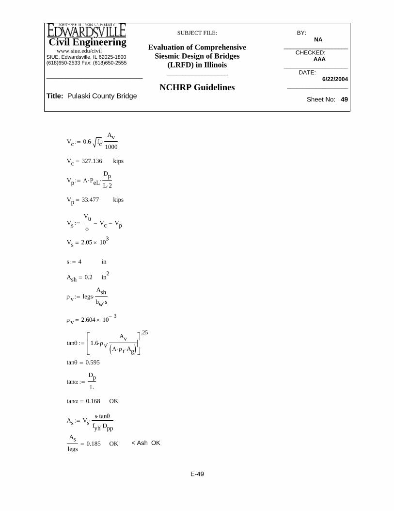
Civil Engineering www.siue.edu/civilSIUE, Edwardsville, IL 62025-1800(618)650-2533 Fax: (618)650-2555
______________________________
Title: Pulaski County Bridge
SUBJECT FILE:
Evaluation of Comprehensive Siesmic Design of Bridges
(LRFD) in Illinois___________________
NCHRP Guidelines
BY:_____________ NA________
____________________CHECKED: _____
AAA_______ ____________________
DATE:__________ 6/22/2004
___________________
Sheet No: 49
< Ash OKOKAslegs
0.185=
As Vss tanθ⋅
fyh Dpp⋅⋅:=
OKtanα 0.168=
tanαDpL
:=
tanθ 0.595=
tanθ 1.6 ρv⋅Av
Λ ρt⋅ Ag⋅( )⋅
⎡⎢⎣
⎤⎥⎦
.25
:=
ρv 2.604 10 3−×=
ρv legsAshbw s⋅⋅:=
in2Ash 0.2=
ins 4:=
Vs 2.05 103×=
VsVuφ
Vc− Vp−:=
kipsVp 33.477=
Vp Λ PeL⋅DpL 2⋅⋅:=
kipsVc 327.136=
Vc 0.6 fc⋅Av
1000⋅:=
E-49

Civil Engineering www.siue.edu/civilSIUE, Edwardsville, IL 62025-1800(618)650-2533 Fax: (618)650-2555
______________________________
Title: Pulaski County Bridge
SUBJECT FILE:
Evaluation of Comprehensive Siesmic Design of Bridges
(LRFD) in Illinois___________________
NCHRP Guidelines
BY:_____________ NA________
____________________CHECKED: _____
AAA_______ ____________________
DATE:__________ 6/22/2004
___________________
Sheet No: 50
kipsVuL 2.17 103×=
k ft−Mp_botL 3.707 104×=
Vu 2.17 103×=
ftLp 7.252=
Lph 4−( )
121
tanθ.5 tanθ⋅+⎛⎜
⎝⎞⎠
⋅:=
tanθ 0.595=
Final check for the plastic hinge zone(Guide Spec. 4.9.1)
OKsmax 15=
smax .25 60⋅:=
OKin2 Ash<Abh
legs_antibuckling0.393=
Abh Ab 0.09⋅6060⋅:=
Ab 1.56 N⋅:=
#6Ash 0.44:=
ins 4=
Required spacing of anti-bucklinginsnew 8.46=
Maximum spacing of tiessnew 6 db⋅:=
Diameter of longitudinal rebarsindb 1.41=
legs_antibuckling 70:=
Anti buckling steel(Guide Spec. 8.8.2.5)
E-50

Civil Engineering www.siue.edu/civilSIUE, Edwardsville, IL 62025-1800(618)650-2533 Fax: (618)650-2555
______________________________
Title: Pulaski County Bridge
SUBJECT FILE:
Evaluation of Comprehensive Siesmic Design of Bridges
(LRFD) in Illinois___________________
NCHRP Guidelines
BY:_____________ NA________
____________________CHECKED: _____
AAA_______ ____________________
DATE:__________ 6/22/2004
___________________
Sheet No: 51
<5 so design anthology applies ld
1.483=
ftl 21.354=
ftlH12
:=
ftd 14.4=
d .9 h⋅:=
ftb 4:=
fth 16:=
psify 60000:=
psifc 3500:=
Shear design (pier 2)
Deep beam design (Source: Reinforcement concrete, Nawy, 3rd edition, section 6.9)
Summary of transverse reinforcement pier 2#6@8" with 70 legs in 7.5' of bottom #4@8" with 23 legs in 7.5' of bottom #4@6" with 23 legs in the rest of the wall
1.512
4400 εy⋅ db⋅ .0812Mp_botL
Vu⋅+
⎛⎜⎝
⎞
⎠⋅ 3.655=
controlsftMp_botL
Vu1 .85
Mp_botL1.5
⎛⎜⎝
⎞⎠
Mp_botL⋅−
⎡⎢⎢⎢⎣
⎤⎥⎥⎥⎦
⋅ 7.403=
E-51

Civil Engineering www.siue.edu/civilSIUE, Edwardsville, IL 62025-1800(618)650-2533 Fax: (618)650-2555
______________________________
Title: Pulaski County Bridge
SUBJECT FILE:
Evaluation of Comprehensive Siesmic Design of Bridges
(LRFD) in Illinois___________________
NCHRP Guidelines
BY:_____________ NA________
____________________CHECKED: _____
AAA_______ ____________________
DATE:__________ 6/22/2004
___________________
Sheet No: 52
VsVΦ
Φ Vc⋅−:=
kipsVc 1.219 103×=
Vc min Vc Vcmax,( ):=
Vcmax 2.944 103×=
Vcmax 6 fc⋅ b⋅ d⋅1441000⋅:=
kipsVc 1.219 103×=
Vc A2 1.9 fc⋅ 2500 ρt⋅V d⋅M
⋅+⎛⎜⎝
⎞⎠
⋅ b⋅ d⋅1441000⋅:=
ρt 0.033=
A2 1:=Hence useA2 <1But
A2 < 3.5 OKA2 2.499−=
A2 3.5 2.5MV d⋅⋅−:=
A1 2.4=
A1MV d⋅
:=
ΦVnkipsΦ 8 fc⋅ b⋅ d⋅1441000⋅⎛⎜
⎝⎞⎠
⋅ 3.533 103×=
k ft−M 41430:=
kipsV 1.199 103×=
for shearΦ 0.90:=
E-52

Civil Engineering www.siue.edu/civilSIUE, Edwardsville, IL 62025-1800(618)650-2533 Fax: (618)650-2555
______________________________
Title: Pulaski County Bridge
SUBJECT FILE:
Evaluation of Comprehensive Siesmic Design of Bridges
(LRFD) in Illinois___________________
NCHRP Guidelines
BY:_____________ NA________
____________________CHECKED: _____
AAA_______ ____________________
DATE:__________ 6/22/2004
___________________
Sheet No: 53
j 0.741=
j .2l 2 h⋅+( )
d:=
> 1 so jd=0.6llh
1.335=
k ft−M 4.143 104×=
Φ 1:=
Flexure design for deep beam
inSvmax 16=
Svmax min 18b 12⋅
3,⎛⎜
⎝⎞⎠
:=
inSv 249.571=
Sv12
2 .79⋅ 1⋅hd
+
⎛⎜⎜⎝
⎞
⎠
K1 K2−( )⋅:=
Sv
2 .79⋅ 1hd
+⎛⎜⎝
⎞⎠
⋅⎡⎢⎣
⎤⎥⎦
12 K1 K2−( )⋅⎡⎣ ⎤⎦:=
K2Vs 1000⋅
fy d⋅ 12⋅:=
K1305.75
4.5
11hd
−⎛⎜⎝
⎞⎠
12⋅:=
Shear reinforcement is not requiredkipsVs 234.91=
E-53

Civil Engineering www.siue.edu/civilSIUE, Edwardsville, IL 62025-1800(618)650-2533 Fax: (618)650-2555
______________________________
Title: Pulaski County Bridge
SUBJECT FILE:
Evaluation of Comprehensive Siesmic Design of Bridges
(LRFD) in Illinois___________________
NCHRP Guidelines
BY:_____________ NA________
____________________CHECKED: _____
AAA_______ ____________________
DATE:__________ 6/22/2004
___________________
Sheet No: 54
kipsVr 1.61 103×=
Vr3
1000fc bw 3−( ) h⋅:=
insh 4:=
Number of horizontal reinforcementN_h 51.273=
N_hAsh_rq
Ash:=
2 #6Ash 0.44=
in2Ash_rq 22.56=
Ash_rq ρhmin bw 4−( )⋅ h⋅:=
ρhmin .0025:=
h 48:=
MCEER Guide Spec. 8.8.3
Shear design in transverse direction
b 2.5 12⋅:=< 305.75 in2 OKin2Asmin 27.648=
Asmin max 3fc
fy⋅ b⋅ d⋅ 144⋅ 200 b⋅
d 144⋅
fy⋅,
⎛⎜⎜⎝
⎞
⎠:=
< 307.75 in2 OKin2As 64.709=
AsM 12000⋅
Φ fy⋅ j⋅ d⋅ 12⋅:=
ftj d⋅ 10.671=
E-54

Civil Engineering www.siue.edu/civilSIUE, Edwardsville, IL 62025-1800(618)650-2533 Fax: (618)650-2555
______________________________
Title: Pulaski County Bridge
SUBJECT FILE:
Evaluation of Comprehensive Siesmic Design of Bridges
(LRFD) in Illinois___________________
NCHRP Guidelines
BY:_____________ NA________
____________________CHECKED: _____
AAA_______ ____________________
DATE:__________ 6/22/2004
___________________
Sheet No: 55
kips (So use 34#8 horizontal reinforcement)Vrq 1.651 103×=
kipsVn 1.786 103×=
Vn φ .756 fc⋅ ρh fyh⋅ 1000⋅+( )⋅ bw 3−( )⋅h
1000⋅:=
insh 4:=
Number of horizontal reinforcementN_h 29.738=
N_hAsh_rq
Ash:=
2 #6Ash 0.88:=
in2Ash_rq 26.17=
Ash_rq ρh bw 4−( )⋅ h⋅:=
ρh .0029:=
kips (So minimum horizontal reinforcement is not adequate for this pier)Vrq 1651:=
kipsV 1.59 103×=
V min Vn Vr,( ):=
kipsVn 1.59 103×=
Vn φ .756 fc⋅ ρhmin fyh⋅ 1000⋅+( )⋅ bw 3−( )⋅h
1000⋅:=
E-55
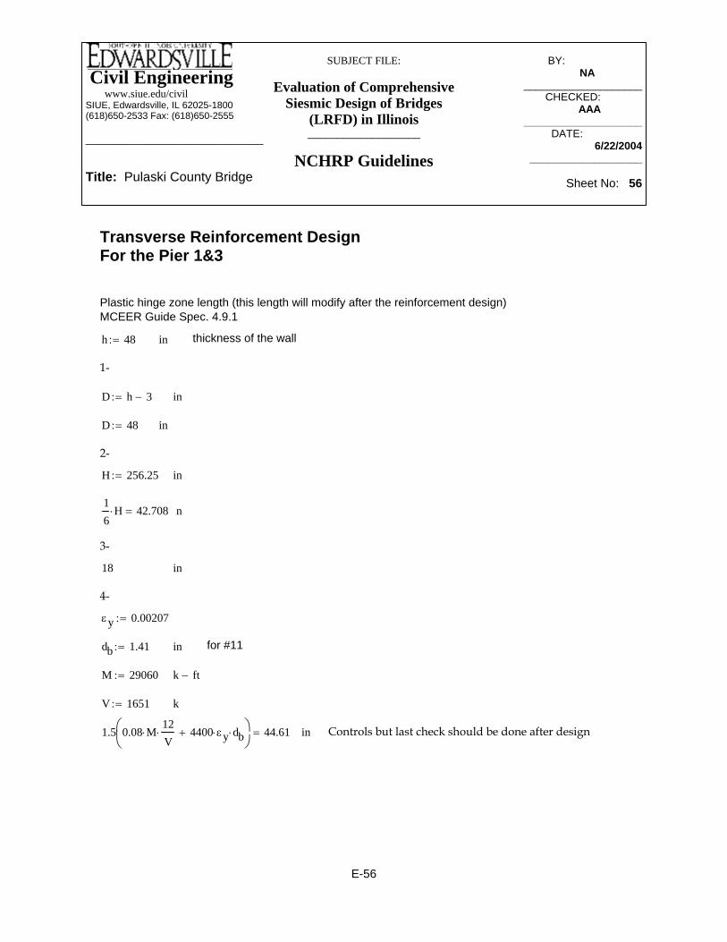
Civil Engineering www.siue.edu/civilSIUE, Edwardsville, IL 62025-1800(618)650-2533 Fax: (618)650-2555
______________________________
Title: Pulaski County Bridge
SUBJECT FILE:
Evaluation of Comprehensive Siesmic Design of Bridges
(LRFD) in Illinois___________________
NCHRP Guidelines
BY:_____________ NA________
____________________CHECKED: _____
AAA_______ ____________________
DATE:__________ 6/22/2004
___________________
Sheet No: 56
Controls but last check should be done after design in1.5 0.08 M⋅12V
⋅ 4400 εy⋅ db⋅+⎛⎜⎝
⎞⎠
44.61=
kV 1651:=
k ft−M 29060:=
for #11indb 1.41:=
εy 0.00207:=
4-
in18
3-
in16
H⋅ 42.708=
inH 256.25:=
2-
inD 48:=
inD h 3−:=
1-
thickness of the wallinh 48:=
Plastic hinge zone length (this length will modify after the reinforcement design)MCEER Guide Spec. 4.9.1
Transverse Reinforcement DesignFor the Pier 1&3
E-56

Civil Engineering www.siue.edu/civilSIUE, Edwardsville, IL 62025-1800(618)650-2533 Fax: (618)650-2555
______________________________
Title: Pulaski County Bridge
SUBJECT FILE:
Evaluation of Comprehensive Siesmic Design of Bridges
(LRFD) in Illinois___________________
NCHRP Guidelines
BY:_____________ NA________
____________________CHECKED: _____
AAA_______ ____________________
DATE:__________ 6/22/2004
___________________
Sheet No: 57
kips Axial earthquake force
MtopL 0:= k ft−
MbotL M:=
OS 1.5:= Over strength factor
Mp_topL OS MtopL⋅:=
Mp_topL 0= k ft−
Mp_botL OS MbotL⋅:=
Mp_botL 4.359 104×= k ft−
VuLMp_topL Mp_botL+( ) 12⋅
L R⋅:=
VuL 2.552 103×= kips
Vu_analysisVR
:= kips
Wall pier transverse reinforcementMethod 2: Explicit Approach(Guide Spec 8.8.2.3)Pier 1&3192"X48" (3.32% steel, 86#11 in two layers at top and 12#11 each side)
N 196:= number of longitudinal reinforcement
R 0.8:= R-factor for joint (table 3.1-2)
L H:= in Height of the pier
Ab 1.56:= in2 Area of rebars for longitudinal rebar
For longitudinal case which is govern for this bridge. For transverse direction, value of 2 is used for the case of fixed - fixed.Λ 1:= fixed - free
Pd 470:= kips Axial dead load in the pier
Pe 164:=
E-57
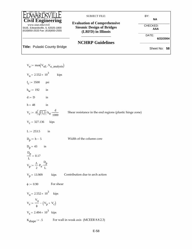
Civil Engineering www.siue.edu/civilSIUE, Edwardsville, IL 62025-1800(618)650-2533 Fax: (618)650-2555
______________________________
Title: Pulaski County Bridge
SUBJECT FILE:
Evaluation of Comprehensive Siesmic Design of Bridges
(LRFD) in Illinois___________________
NCHRP Guidelines
BY:_____________ NA________
____________________CHECKED: _____
AAA_______ ____________________
DATE:__________ 6/22/2004
___________________
Sheet No: 58
Dp h 5−:= Width of the column core
Dp 43= in
DpL
0.17=
VpΛ
2Pe⋅
DpL
⋅:=
Vp 13.909= kips Contribution due to arch action
φ 0.90:= For shear
Vu 2.552 103×= kips
VsVuφ
Vp Vc+( )−:=
Vs 2.494 103×= kips
Kshape .5:= For wall in weak axis (MCEER 8.8.2.3)
Vu max VuL Vu_analysis,( ):=
Vu 2.552 103×= kips
fc 3500:= psi
bw 192:= in
d D:= in
h 48= in
Vc .6 fc( )⎡⎣ ⎤⎦ bw⋅d
1000⋅:= Shear resistance in the end regions (plastic hinge zone)
Vc 327.136= kips
L 253.5:= in
E-58

Civil Engineering www.siue.edu/civilSIUE, Edwardsville, IL 62025-1800(618)650-2533 Fax: (618)650-2555
______________________________
Title: Pulaski County Bridge
SUBJECT FILE:
Evaluation of Comprehensive Siesmic Design of Bridges
(LRFD) in Illinois___________________
NCHRP Guidelines
BY:_____________ NA________
____________________CHECKED: _____
AAA_______ ____________________
DATE:__________ 6/22/2004
___________________
Sheet No: 59
#4 Area of transverse reinforcement (ties)
legs 13:= Number of legs
ρv_pr legsAshbw s⋅⋅:=
ρv_pr 3.385 10 3−×=
Ag bw h⋅:=
Ag 9.216 103×= in2
tanθ 1.6 ρv_pr⋅Av
Λ ρt⋅ Ag⋅⋅
⎛⎜⎝
⎞
⎠
.25
:=
tanθ 0.636=
Dpp h 4−:= Width of the perimeter transverse direction
Avs sVs
fyh Dpp⋅⋅ tanθ⋅:=
Avslegs
0.185= in2 < Ash OK
fyh 60:= ksi For the transverse and longitudinal steel
fsu 1.5 fyh⋅:= Ultimate tensile stress of the longitudinal reinforcement
fsu 90= ksi
Av bw d⋅:= Shear area
Av 9.216 103×= in2
ρt .0332:= Longitudinal reinforcement ratio
s 4:= in < 4" OK (MCEER 8.8.2.4) for plastic hinge zone
Ash .2:=
E-59

Civil Engineering www.siue.edu/civilSIUE, Edwardsville, IL 62025-1800(618)650-2533 Fax: (618)650-2555
______________________________
Title: Pulaski County Bridge
SUBJECT FILE:
Evaluation of Comprehensive Siesmic Design of Bridges
(LRFD) in Illinois___________________
NCHRP Guidelines
BY:_____________ NA________
____________________CHECKED: _____
AAA_______ ____________________
DATE:__________ 6/22/2004
___________________
Sheet No: 60
ρv_pr 2.257 10 3−×=
ρv_pr legs_outplasticAshmbw sm⋅⋅:=
#4Ashm .2:=
Maximum spacing (MCEER 8.8.2.6)insm 6:=
kipsVs 1.731 103×=
VsVuφ
Vp Vc+( )−:=
Vp 13.909=
kipsVc 1.09 103×=
Shear resistance of concrete out side of the plastic hinge zoneVc 2 fc⋅ bw⋅d
1000⋅:=
legs_outplastic 13:=
Outside the plastic hinge zoneMethod 2: Explicit Approach8.8.2.3
< Ash provided OKin2Avslegs_new
0.176=
legs_new 26:=
Avs ρv bw⋅ s⋅:=
ρv 5.965 10 3−×=
For fixed - fixed case of transverse directionρv Kshape 2⋅ Λρtφ
⋅fsufyh⋅
AgAv⋅
DpL
⋅ tanθ⋅:=
Method 1: Implicit Shear Detailing Approach(Guide Spec. 8.8.2.3)
E-60

Civil Engineering www.siue.edu/civilSIUE, Edwardsville, IL 62025-1800(618)650-2533 Fax: (618)650-2555
______________________________
Title: Pulaski County Bridge
SUBJECT FILE:
Evaluation of Comprehensive Siesmic Design of Bridges
(LRFD) in Illinois___________________
NCHRP Guidelines
BY:_____________ NA________
____________________CHECKED: _____
AAA_______ ____________________
DATE:__________ 6/22/2004
___________________
Sheet No: 61
Strain energy capacityksiUsf 15.95:=
ksifyh 60=
legs 13=
Transverse reinforcement for confinement at plastic hinges (Pmax column) (Guide Spec. 8.8.2.4)
Use method 2ρpr 4.688 10 3−×=
ρpr legs_newAshmbw sm⋅⋅:=
ρvstar 3.993 10 3−×=
ρvstar ρv2 fc⋅
fyh 1000⋅−:=
fyh 60=
legs_new 27:=
Method 1: Implicit Shear Detailing Approach
< Ash OKin2Avslegs_outplastic
0.174=
Avs smVs
fyh Dpp⋅⋅ tanθ⋅:=
inDpp 44=
tanθ 0.574=
tanθ 1.6 ρv_pr⋅Av
Λ ρt⋅ Ag⋅⋅
⎛⎜⎝
⎞
⎠
.25
:=
Ag 9.216 103×=
E-61

Civil Engineering www.siue.edu/civilSIUE, Edwardsville, IL 62025-1800(618)650-2533 Fax: (618)650-2555
______________________________
Title: Pulaski County Bridge
SUBJECT FILE:
Evaluation of Comprehensive Siesmic Design of Bridges
(LRFD) in Illinois___________________
NCHRP Guidelines
BY:_____________ NA________
____________________CHECKED: _____
AAA_______ ____________________
DATE:__________ 6/22/2004
___________________
Sheet No: 62
OKinsmax 4.151=
smax legs_pmaxAsh
Dpp ρs2⋅⋅:=
legs_pmax Ash⋅
s Dp⋅0.012=
Include the area of total legs in both direction of cross section (Guide Spec. 8.8.2.4)
legs_pmax 10:=
legs 13=
Dp 43=
OKρs2 0.011=
ρs2 0.008fc
1000Usf⋅ 15
1000Pefc Ag⋅
ρt1000 fyh⋅
fc⋅+
⎛⎜⎝
⎞
⎠
2
⋅AgAc
⎛⎜⎝
⎞
⎠
2
⋅ 1−⎡⎢⎢⎣
⎤⎥⎥⎦
⋅:=
Factored axial load include seismic effectkipsPe 634=
Pe Pd Pe+:=
fc 3.5 103×=
Ag 9.216 103×=
ρt 0.033=
ρs1 0.015=
ρs1 legsAsh
Dpp s⋅⋅:=
< 4" OK (MCEER 8.8.2.4)ins 4:=
in2Ac 7.812 103×=
Ac bw 6−( ) h 6−( )⋅:=
in2Ash 0.2=
E-62

Civil Engineering www.siue.edu/civilSIUE, Edwardsville, IL 62025-1800(618)650-2533 Fax: (618)650-2555
______________________________
Title: Pulaski County Bridge
SUBJECT FILE:
Evaluation of Comprehensive Siesmic Design of Bridges
(LRFD) in Illinois___________________
NCHRP Guidelines
BY:_____________ NA________
____________________CHECKED: _____
AAA_______ ____________________
DATE:__________ 6/22/2004
___________________
Sheet No: 63
kipsVc 327.136=
Vc 0.6 fc⋅Av
1000⋅:=
Av 9.216 103×=
kipsVu 2.579 103×=
VuMp_bot 12⋅
L R⋅:=
Mp_bot OS MbotL⋅:=
kipsPeL 329=
PeL Pd OS PeminL Pd−( )⋅+:=
OS 1.5=
k ft−MbotL 2.906 104×=
k ft−Mp_top 0:=
kipsPeminL 376=
For the uplift effectkipsPeminL Pd .8⋅:=
kipsPd 470=
Explicit Shear Detailing Approach (Pmin Column)(Guide Spec. 8.8.2.3) In longitudinal direction
ins 4=
ρs 0.015=
ρs max ρs1 ρs2,( ):=
E-63

Civil Engineering www.siue.edu/civilSIUE, Edwardsville, IL 62025-1800(618)650-2533 Fax: (618)650-2555
______________________________
Title: Pulaski County Bridge
SUBJECT FILE:
Evaluation of Comprehensive Siesmic Design of Bridges
(LRFD) in Illinois___________________
NCHRP Guidelines
BY:_____________ NA________
____________________CHECKED: _____
AAA_______ ____________________
DATE:__________ 6/22/2004
___________________
Sheet No: 64
Diameter of longitudinal rebarsindb 1.41=
legs_antibuckling 70:=
Anti buckling steel(Guide Spec. 8.8.2.5)
< Ash OKOKAslegs
0.186=
As Vss tanθ⋅
fyh Dpp⋅⋅:=
OKtanα 0.17=
tanαDpL
:=
tanθ 0.636=
tanθ 1.6 ρv⋅Av
Λ ρt⋅ Ag⋅( )⋅
⎡⎢⎣
⎤⎥⎦
.25
:=
ρv 3.385 10 3−×=
ρv legsAshbw s⋅⋅:=
in2Ash 0.2=
ins 4:=
Vs 2.511 103×=
VsVuφ
Vc− Vp−:=
kipsVp 27.903=
Vp Λ PeL⋅DpL 2⋅⋅:=
E-64

Civil Engineering www.siue.edu/civilSIUE, Edwardsville, IL 62025-1800(618)650-2533 Fax: (618)650-2555
______________________________
Title: Pulaski County Bridge
SUBJECT FILE:
Evaluation of Comprehensive Siesmic Design of Bridges
(LRFD) in Illinois___________________
NCHRP Guidelines
BY:_____________ NA________
____________________CHECKED: _____
AAA_______ ____________________
DATE:__________ 6/22/2004
___________________
Sheet No: 65
controlsftMp_botL
Vu1 .85
Mp_botL1.5
⎛⎜⎝
⎞⎠
Mp_botL⋅−
⎡⎢⎢⎢⎣
⎤⎥⎥⎥⎦
⋅ 7.323=
kipsVuL 2.552 103×=
k ft−Mp_botL 4.359 104×=
Vu 2.579 103×=
ftLp 6.934=
Lph 4−( )
121
tanθ.5 tanθ⋅+⎛⎜
⎝⎞⎠
⋅:=
tanθ 0.636=
Final check for the plastic hinge zone(Guide Spec. 4.9.1)
OKsmax 15=
smax .25 60⋅:=
< Ash OKAbh
legs_antibuckling0.393=
Abh Ab 0.09⋅6060⋅:=
Ab 1.56 N⋅:=
#6Ash .44:=
ins 4=
Required spacing of anti-bucklinginsnew 8.46=
Maximum spacing of tiessnew 6 db⋅:=
E-65

Civil Engineering www.siue.edu/civilSIUE, Edwardsville, IL 62025-1800(618)650-2533 Fax: (618)650-2555
______________________________
Title: Pulaski County Bridge
SUBJECT FILE:
Evaluation of Comprehensive Siesmic Design of Bridges
(LRFD) in Illinois___________________
NCHRP Guidelines
BY:_____________ NA________
____________________CHECKED: _____
AAA_______ ____________________
DATE:__________ 6/22/2004
___________________
Sheet No: 66
k ft−M 39190:=
kipsV 1.651 103×=
for shearΦ 0.90:=
<5 so design anthology applies ld
1.467=
ftl 21.125=
ftlL12
:=
ftd 14.4=
d .9 h⋅:=
ftb 4:=
fth 16:=
psify 60000:=
psifc 3500:=
Shear design (pier 1&3)
Deep beam design (Source: Reinforcement concrete, Nawy, 3rd edition, section 6.9)
Summary of transverse reinforcement pier 1 & 3#6@6" with 70 legs in 7.3' of bottom #4@4" with 23 legs in 7.3' of bottom #4@6" with 23 legs in the rest of the wall
1.512
4400 εy⋅ db⋅ .0812Mp_botL
Vu⋅+
⎛⎜⎝
⎞
⎠⋅ 3.633=
E-66

Civil Engineering www.siue.edu/civilSIUE, Edwardsville, IL 62025-1800(618)650-2533 Fax: (618)650-2555
______________________________
Title: Pulaski County Bridge
SUBJECT FILE:
Evaluation of Comprehensive Siesmic Design of Bridges
(LRFD) in Illinois___________________
NCHRP Guidelines
BY:_____________ NA________
____________________CHECKED: _____
AAA_______ ____________________
DATE:__________ 6/22/2004
___________________
Sheet No: 67
K2Vs 1000⋅
fy d⋅ 12⋅:=
K1305.75
4.5
11hd
−⎛⎜⎝
⎞⎠
12⋅:=
Shear reinforcement is not requiredkipsVs 1.834 103×=
VsVΦ
Φ Vc⋅−:=
kipsVc 0:=
Vc min Vc Vcmax,( ):=
Vcmax 2.944 103×=
Vcmax 6 fc⋅ b⋅ d⋅1441000⋅:=
use 0kipsVc 838.372−=
Vc A2 1.9 fc⋅ 2500 ρt⋅V d⋅M
⋅+⎛⎜⎝
⎞⎠
⋅ b⋅ d⋅1441000⋅:=
ρt 0.033=
A2 < 3.5 OKA2 0.621−=
A2 3.5 2.5MV d⋅⋅−:=
A1 1.648=
A1MV d⋅
:=
ΦVnkipsΦ 8 fc⋅ b⋅ d⋅1441000⋅⎛⎜
⎝⎞⎠
⋅ 3.533 103×=
E-67

Civil Engineering www.siue.edu/civilSIUE, Edwardsville, IL 62025-1800(618)650-2533 Fax: (618)650-2555
______________________________
Title: Pulaski County Bridge
SUBJECT FILE:
Evaluation of Comprehensive Siesmic Design of Bridges
(LRFD) in Illinois___________________
NCHRP Guidelines
BY:_____________ NA________
____________________CHECKED: _____
AAA_______ ____________________
DATE:__________ 6/22/2004
___________________
Sheet No: 68
< 305.75 in2 OKin2Asmin 27.648=
Asmin max 3fc
fy⋅ b⋅ d⋅ 144⋅ 200 b⋅
d 144⋅
fy⋅,
⎛⎜⎜⎝
⎞
⎠:=
< 307.75 in2 OKin2As 61.475=
AsM 12000⋅
Φ fy⋅ j⋅ d⋅ 12⋅:=
ftj d⋅ 10.625=
j 0.738=
j .2l 2 h⋅+( )
d:=
> 1 so jd=0.6llh
1.32=
k ft−M 3.919 104×=
Φ 1:=
Flexure design for deep beam
inSvmax 16=
Svmax min 18b 12⋅
3,⎛⎜
⎝⎞⎠
:=
inSv 248.883=
Sv12
2 .79⋅ 1⋅hd
+
⎛⎜⎜⎝
⎞
⎠
K1 K2−( )⋅:=
Sv
2 .79⋅ 1hd
+⎛⎜⎝
⎞⎠
⋅⎡⎢⎣
⎤⎥⎦
12 K1 K2−( )⋅⎡⎣ ⎤⎦:=
E-68

Civil Engineering www.siue.edu/civilSIUE, Edwardsville, IL 62025-1800(618)650-2533 Fax: (618)650-2555
______________________________
Title: Pulaski County Bridge
SUBJECT FILE:
Evaluation of Comprehensive Siesmic Design of Bridges
(LRFD) in Illinois___________________
NCHRP Guidelines
BY:_____________ NA________
____________________CHECKED: _____
AAA_______ ____________________
DATE:__________ 6/22/2004
___________________
Sheet No: 69
kips (So minimum horizontal reinforcement is not adequate for this pier)Vrq 1651:=
kipsV 1.59 103×=
V min Vn Vr,( ):=
kipsVn 1.59 103×=
Vn φ .756 fc⋅ ρhmin fyh⋅ 1000⋅+( )⋅ bw 3−( )⋅h
1000⋅:=
kipsVr 1.61 103×=
Vr3
1000fc bw 3−( ) h⋅:=
insh 4:=
Number of horizontal reinforcementN_h 51.273=
N_hAsh_rq
Ash:=
2 #6Ash 0.44=
in2Ash_rq 22.56=
Ash_rq ρhmin bw 4−( )⋅ h⋅:=
ρhmin .0025:=
h 48:=
MCEER Guide Spec. 8.8.3
Shear design in transverse direction
E-69

Civil Engineering www.siue.edu/civilSIUE, Edwardsville, IL 62025-1800(618)650-2533 Fax: (618)650-2555
______________________________
Title: Pulaski County Bridge
SUBJECT FILE:
Evaluation of Comprehensive Siesmic Design of Bridges
(LRFD) in Illinois___________________
NCHRP Guidelines
BY:_____________ NA________
____________________CHECKED: _____
AAA_______ ____________________
DATE:__________ 6/22/2004
___________________
Sheet No: 70
ρh .0029:=
Ash_rq ρh bw 4−( )⋅ h⋅:=
Ash_rq 26.17= in2
Ash 0.88:= 2 #6
N_hAsh_rq
Ash:=
N_h 29.738= Number of horizontal reinforcement
sh 4:= in
Vn φ .756 fc⋅ ρh fyh⋅ 1000⋅+( )⋅ bw 3−( )⋅h
1000⋅:=
Vn 1.786 103×= kips
Vrq 1.651 103×= kips (So use 60#6 horizontal reinforcement)
E-70

Civil Engineering www.siue.edu/civilSIUE, Edwardsville, IL 62025-1800(618)650-2533 Fax: (618)650-2555
______________________________
Title: Pulaski County Bridge
SUBJECT FILE:
Evaluation of Comprehensive Siesmic Design of Bridges
(LRFD) in Illinois___________________
NCHRP Guidelines
BY:_____________ NA________
____________________CHECKED: _____
AAA_______ ____________________
DATE:__________ 6/22/2004
___________________
Sheet No: 71
For the longitudinal steel
L 256.25:= in Height of the pier
Ab 1.56:= in2 Area of rebars for longitudinal rebar
Pd 570:= kips Axial dead load in the pier
Pe 0:= kips Axial earthquake force
MbotL 24711:= k ft−
OS 1.5:= Over strength factor
Mp_botL OS MbotL⋅:=
Mp_botL 3.707 104×= k ft−
Pier 2Wall pier connection designMethod 1: Implicit Shear Detailing Approach (Guide spec. 8.8.4.1, 8.8.2.3, 8.8.2.4)192"X48" (3.32% steel, 86#11 in two layers at top and 12#11 each side)
N 196:= number of longitudinal reinforcement
bw 48:= in Height of pile cap
Hc 48:= in Height of the joint
h 48:= in Dimension of the column
D h 3−:= in
D 45= in
R 0.8:= R-factor for joint (table 3.1-2)
εy .00207:=
E-71

Civil Engineering www.siue.edu/civilSIUE, Edwardsville, IL 62025-1800(618)650-2533 Fax: (618)650-2555
______________________________
Title: Pulaski County Bridge
SUBJECT FILE:
Evaluation of Comprehensive Siesmic Design of Bridges
(LRFD) in Illinois___________________
NCHRP Guidelines
BY:_____________ NA________
____________________CHECKED: _____
AAA_______ ____________________
DATE:__________ 6/22/2004
___________________
Sheet No: 72
ksi
Av bw d⋅:= Shear area
Av 8.64 103×= in2
ρt .0332:= Longitudinal reinforcement ratio
s 4:= in < 4" OK (MCEER 8.8.2.4) for plastic hinge zone
Ash .2:= #4 Area of transverse reinforcement (ties)
legs 16:= Number of legs
ρv_pr legsAshbw s⋅⋅:=
ρv_pr 4.167 10 3−×=
Ag bw h⋅:=
Ag 9.216 103×= in2
fc 3500:= psi
bw 192:= in
d D:= in
L 256.25= in
Dp h 4−:= Width of the column core
Dp 44= in
φ 0.90:= For shear
fyh 60:= ksi For the transverse and longitudinal steel
fsu 1.5 fyh⋅:= Ultimate tensile stress of the longitudinal reinforcement
fsu 90=
E-72
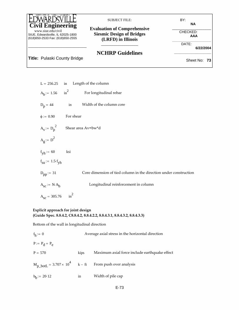
Civil Engineering www.siue.edu/civilSIUE, Edwardsville, IL 62025-1800(618)650-2533 Fax: (618)650-2555
______________________________
Title: Pulaski County Bridge
SUBJECT FILE:
Evaluation of Comprehensive Siesmic Design of Bridges
(LRFD) in Illinois___________________
NCHRP Guidelines
BY:_____________ NA________
____________________CHECKED: _____
AAA_______ ____________________
DATE:__________ 6/22/2004
___________________
Sheet No: 73
Asc N Ab⋅:= Longitudinal reinforcement in column
Asc 305.76= in2
Explicit approach for joint design (Guide Spec. 8.8.4.2, C8.8.4.2, 8.8.4.2.2, 8.8.4.3.1, 8.8.4.3.2, 8.8.4.3.3)
Bottom of the wall in longitudinal direction
fh 0:= Average axial stress in the horizontal direction
P Pd Pe+:=
P 570= kips Maximum axial force include earthquake effect
Mp_botL 3.707 104×= k ft− From push over analysis
bb 20 12⋅:= in Width of pile cap
L 256.25= in Length of the column
Ab 1.56:= in2 For longitudinal rebar
Dp 44= in Width of the column core
φ 0.90:= For shear
Av Dp2
:= Shear area Av=bw*d
Ag D2:=
fyh 60:= ksi
fsu 1.5 fyh⋅:=
Dpp 31:= Core dimension of tied column in the direction under construction
E-73

Civil Engineering www.siue.edu/civilSIUE, Edwardsville, IL 62025-1800(618)650-2533 Fax: (618)650-2555
______________________________
Title: Pulaski County Bridge
SUBJECT FILE:
Evaluation of Comprehensive Siesmic Design of Bridges
(LRFD) in Illinois___________________
NCHRP Guidelines
BY:_____________ NA________
____________________CHECKED: _____
AAA_______ ____________________
DATE:__________ 6/22/2004
___________________
Sheet No: 74
Maximum tension stresspt_max3.5
1000fc⋅:=
pt 2.288−=
Principal tension stressptfh fv+( )
2
fh fv−( )2
⎡⎢⎣
⎤⎥⎦
2
vhv2
+−:=
ksivhv 2.288=
Joint shear stressvhvMp_botL 12⋅
hb hc⋅ bje⋅:=
inbje 90=
effective joint width for shear stress calculationsbje 2hc:=
inhc 45=
Dimension of columnhc D:=
inhb 48=
Joint depthhb Hc:=
ksifv 0=
Average axial stress in the vertical directionfvPe
Amid:=
in2Amid 2.232 104×=
Amid bb Lmid_dept_jt⋅:=
inLmid_dept_jt 93=
Lmid_dept_jt D Hc+:=
E-74

Civil Engineering www.siue.edu/civilSIUE, Edwardsville, IL 62025-1800(618)650-2533 Fax: (618)650-2555
______________________________
Title: Pulaski County Bridge
SUBJECT FILE:
Evaluation of Comprehensive Siesmic Design of Bridges
(LRFD) in Illinois___________________
NCHRP Guidelines
BY:_____________ NA________
____________________CHECKED: _____
AAA_______ ____________________
DATE:__________ 6/22/2004
___________________
Sheet No: 75
25#9 in 40" length each sideAh 24.461=
Horizontal reinforcement (Guide Spec. 8.8.4.3.3)Ah 0.08 Asc⋅:=
inld9 22.791=
in0.3 1.128⋅ fyh⋅ 20.304=
Development length for #9 (AASHTO LRFD 5.11.2.2.1-1)ld9 .63 1.128⋅fyh
fc1000
⋅:=
31#7 in 36" of the jointAclamp
.640.768=
Aclamp 24.461=
Vertical reinforcement (Clamping reinforcement) (Guide Spec. 8.8.4.3.2)Aclamp .08 Asc⋅:=
72#7 vertical legs in (development length) each sideAjv.6
81.536=
Use #7
in2Ajv 48.922=
Vertical reinforcement (Stirrups) (Guide Spec. 8.8.4.3.2)Ajv .16Asc:=
Not OK, we should provide some horizontal reinforcementpc_max 0.875=
Maximum compression stresspc_max.25
1000fc⋅:=
pc 2.288=
Principal compression stresspcfh fv+( )
2
fh fv−( )2
⎡⎢⎣
⎤⎥⎦
2
vhv2
++:=
Not OK, we should provide some horizontal reinforcementpt_max 0.207=
E-75

Civil Engineering www.siue.edu/civilSIUE, Edwardsville, IL 62025-1800(618)650-2533 Fax: (618)650-2555
______________________________
Title: Pulaski County Bridge
SUBJECT FILE:
Evaluation of Comprehensive Siesmic Design of Bridges
(LRFD) in Illinois___________________
NCHRP Guidelines
BY:_____________ NA________
____________________CHECKED: _____
AAA_______ ____________________
DATE:__________ 6/22/2004
___________________
Sheet No: 76
Use #4@4" with 23 legssmax 4.745=
smax legsAsh
Dpp ρs⋅⋅:=
legs 23:=
MCEER8.8.2.4( )OKin in 4≤s 4=
in2Ash .2:=
OKρs_min 3.451 10 3−×=
Minimum required horizontal reinforcement (Guide Spec. 8.8.4.2.2)ρs_min3.5
1000
fcfyh⋅:=
ρs 0.031=
Hoops (Guide Spec. 8.8.4.3.4)ρs .4Asc
ld112
:=
.4 1.41⋅ fyh⋅ 33.84=
inld11 62.539=
ld11 1.25 1.56⋅fyh
fc1000
⋅:=
E-76

Civil Engineering www.siue.edu/civilSIUE, Edwardsville, IL 62025-1800(618)650-2533 Fax: (618)650-2555
______________________________
Title: Pulaski County Bridge
SUBJECT FILE:
Evaluation of Comprehensive Siesmic Design of Bridges
(LRFD) in Illinois___________________
NCHRP Guidelines
BY:_____________ NA________
____________________CHECKED: _____
AAA_______ ____________________
DATE:__________ 6/22/2004
___________________
Sheet No: 77
in Height of the pier
Ab 1:= in2 Area of rebars for longitudinal rebar
For longitudinal case which is govern for this bridge. For transverse direction, value of 2 is used for the case of fixed - fixed.Λ 1:= fixed - free
Pd 470:= kips Axial dead load in the pier
Pe 164:= kips Axial earthquake force
MbotL 29060:= k ft−
OS 1.5:= Over strength factor
Mp_botL OS MbotL⋅:=
Mp_botL 4.359 104×= k ft−
Pier 1&3Wall pier connection designMethod 1: Implicit Shear Detailing Approach (Guide spec. 8.8.4.1, 8.8.2.3, 8.8.2.4)
192"X48" (3.32% steel, 86#11 in two layers at top and 12#11 each side)
N 196= number of longitudinal reinforcement
bw 48:= in Height of pile cap
Hc 48= in Height of the joint
h 48= in Dimension of the column
D h 3−:= in
D 45= in
R 0.8:= R-factor for joint (table 3.1-2)
εy .00207:= For the longitudinal steel
L 253.5:=
E-77

Civil Engineering www.siue.edu/civilSIUE, Edwardsville, IL 62025-1800(618)650-2533 Fax: (618)650-2555
______________________________
Title: Pulaski County Bridge
SUBJECT FILE:
Evaluation of Comprehensive Siesmic Design of Bridges
(LRFD) in Illinois___________________
NCHRP Guidelines
BY:_____________ NA________
____________________CHECKED: _____
AAA_______ ____________________
DATE:__________ 6/22/2004
___________________
Sheet No: 78
fsu 90= ksi
Av bw d⋅:= Shear area
Av 8.82 103×= in2
ρt 0.033= Longitudinal reinforcement ratio
s 4:= in < 4" OK (MCEER 8.8.2.4) for plastic hinge zone
Ash .2:= #4 Area of transverse reinforcement (ties)
legs 16:= Number of legs
ρv_pr legsAshbw s⋅⋅:=
ρv_pr 4.082 10 3−×=
Ag bw h⋅:=
fc 3500:= psi
bw 196:= in
d D:= in
L 253.5= in
Dp h 4−:= Width of the column core
Dp 44= in
φ 0.85:= For shear
fyh 60:= ksi For the transverse and longitudinal steel
fsu 1.5 fyh⋅:= Ultimate tensile stress of the longitudinal reinforcement
E-78

Civil Engineering www.siue.edu/civilSIUE, Edwardsville, IL 62025-1800(618)650-2533 Fax: (618)650-2555
______________________________
Title: Pulaski County Bridge
SUBJECT FILE:
Evaluation of Comprehensive Siesmic Design of Bridges
(LRFD) in Illinois___________________
NCHRP Guidelines
BY:_____________ NA________
____________________CHECKED: _____
AAA_______ ____________________
DATE:__________ 6/22/2004
___________________
Sheet No: 79
in2Asc 196=
Longitudinal reinforcement in columnAsc N Ab⋅:=
Core dimension of tied column in the direction under constructionDpp h 5−:=
fsu 1.5 fyh⋅:=
ksifyh 60:=
Ag D2:=
Shear area Av=bw*dAv Dp2
:=
For shearφ 0.85:=
Width of the column core inDp 44=
For longitudinal rebarin2Ab 1=
Length of the columninL 253.5=
in2Ag 9.408 103×=
E-79

Civil Engineering www.siue.edu/civilSIUE, Edwardsville, IL 62025-1800(618)650-2533 Fax: (618)650-2555
______________________________
Title: Pulaski County Bridge
SUBJECT FILE:
Evaluation of Comprehensive Siesmic Design of Bridges
(LRFD) in Illinois___________________
NCHRP Guidelines
BY:_____________ NA________
____________________CHECKED: _____
AAA_______ ____________________
DATE:__________ 6/22/2004
___________________
Sheet No: 80
Amid bb Lmid_dept_jt⋅:=
Amid 2.79 104×= in2
fvPe
Amid:= Average axial stress in the vertical direction
fv 5.878 10 3−×= ksi
hb Hc:= Joint depth
hb 48= in
hc D:= Dimension of column
hc 45= in
bje 2hc:= effective joint width for shear stress calculations
Explicit approach for joint design (Guide Spec. 8.8.4.2, C8.8.4.2, 8.8.4.2.2, 8.8.4.3.1, 8.8.4.3.2, 8.8.4.3.3)
Bottom of the column in longitudinal direction
fh 0:= Average axial stress in the horizontal direction
P Pd Pe+:=
P 634= kips Maximum axial force include earthquake effect
Mp_botL 4.359 104×= k ft− From push over analysis
bb 25 12⋅:= in Width of pile cap
Lmid_dept_jt D Hc+:=
Lmid_dept_jt 93= in
E-80

Civil Engineering www.siue.edu/civilSIUE, Edwardsville, IL 62025-1800(618)650-2533 Fax: (618)650-2555
______________________________
Title: Pulaski County Bridge
SUBJECT FILE:
Evaluation of Comprehensive Siesmic Design of Bridges
(LRFD) in Illinois___________________
NCHRP Guidelines
BY:_____________ NA________
____________________CHECKED: _____
AAA_______ ____________________
DATE:__________ 6/22/2004
___________________
Sheet No: 81
Aclamp 15.68=
Vertical reinforcement (Clamping reinforcement) (Guide Spec. 8.8.4.3.2)Aclamp .08 Asc⋅:=
53#7 vertical legs in (development length) each sideAjv.6
52.267=
Use #7
in2Ajv 31.36=
Vertical reinforcement (Stirrups) (Guide Spec. 8.8.4.3.2)Ajv .16Asc:=
Not OK, we should provide some horizontal reinforcementpc_max 0.875=
Maximum compression stresspc_max.25
1000fc⋅:=
pc 2.694=
Principal compression stresspcfh fv+( )
2
fh fv−( )2
⎡⎢⎣
⎤⎥⎦
2
vhv2
++:=
Not OK, we should provide some horizontal reinforcementpt_max 0.207=
Maximum tension stresspt_max3.5
1000fc⋅:=
pt 2.688−=
Principal tension stressptfh fv+( )
2
fh fv−( )2
⎡⎢⎣
⎤⎥⎦
2
vhv2
+−:=
ksivhv 2.691=
Joint shear stressvhvMp_botL 12⋅
hb hc⋅ bje⋅:=
inbje 90=
E-81

Civil Engineering www.siue.edu/civilSIUE, Edwardsville, IL 62025-1800(618)650-2533 Fax: (618)650-2555
______________________________
Title: Pulaski County Bridge
SUBJECT FILE:
Evaluation of Comprehensive Siesmic Design of Bridges
(LRFD) in Illinois___________________
NCHRP Guidelines
BY:_____________ NA________
____________________CHECKED: _____
AAA_______ ____________________
DATE:__________ 6/22/2004
___________________
Sheet No: 82
Use #4@4" with 23 legsinsmax 5.337=smax legs
AshDpp ρs⋅⋅:=
legs 23:=
ins 4:=
in2Ash .2:=
OKρs_min 3.451 10 3−×=
Minimum required horizontal reinforcement (Guide Spec. 8.8.4.2.2)ρs_min3.5
1000
fcfyh⋅:=
ρs 0.02=
Hoops (Guide Spec. 8.8.4.3.4)ρs .4Asc
ld112
:=
.4 1.41⋅ fyh⋅ 33.84=
inld11 62.539=
ld11 1.25 1.56⋅fyh
fc1000
⋅:=
16#9 in 40" length each sideAh 15.68=
Horizontal reinforcement (Guide Spec. 8.8.4.3.3)Ah 0.08 Asc⋅:=
inld9 22.791=
in0.3 1.128⋅ fyh⋅ 20.304=
Development length for #9 (AASHTO LRFD 5.11.2.2.1-1)ld9 .63 1.128⋅fyh
fc1000
⋅:=
27#7 in 36" of the jointAclamp
.626.133=
E-82

Civil Engineering www.siue.edu/civilSIUE, Edwardsville, IL 62025-1800(618)650-2533 Fax: (618)650-2555
______________________________
Title: Pulaski County Bridge
SUBJECT FILE:
Evaluation of Comprehensive Siesmic Design of Bridges
(LRFD) in Illinois___________________
NCHRP Guidelines
BY:_____________ NA________
____________________CHECKED: _____
AAA_______ ____________________
DATE:__________ 6/22/2004
___________________
Sheet No: 83
∆ limit .25 C⋅ H⋅:=
C 2.045=
CVW
:=
ftH 21.125=
HL12
:=
kipsV 2448:=
kipsW 1197:= Average axial force at column (Axial load taken from mid hight of Pier 1,2&3= 1197 KIPS)
Pier 1&3
Displacement of 0.52 ft is taken from SAP modelft < ∆limit OK∆ .52:=
ft∆ limit 17.012=
∆ limit .25 C⋅ H⋅:=
C 3.187=
CVW
:=
ftH 21.354=
H256.25
12:=
from SAP modelkipsV 3636:=
kipsW 525 2 308⋅+:=Average axial force at wall (Axial load taken from mid hight of Pier 2=525 kips +Axial load at top of Pier 1&3 =308 kip)
Pier 2
P-∆ Requirements(Guide Spec. 8.3.4)
E-83

Civil Engineering www.siue.edu/civilSIUE, Edwardsville, IL 62025-1800(618)650-2533 Fax: (618)650-2555
______________________________
Title: Pulaski County Bridge
SUBJECT FILE:
Evaluation of Comprehensive Siesmic Design of Bridges
(LRFD) in Illinois___________________
NCHRP Guidelines
BY:_____________ NA________
____________________CHECKED: _____
AAA_______ ____________________
DATE:__________ 6/22/2004
___________________
Sheet No: 84
43" Minimum seat widthftN 3.541=
NN
.3048:=
mN 1.079=
N .1 .0017 L⋅+ .007 H⋅+ .05 H⋅ 1 2BL⋅⎛⎜
⎝⎞⎠
2+⋅+
⎡⎢⎣
⎤⎥⎦
1 1.25 Fv⋅ S1⋅+( )⋅:=
α 0:=
S1 .919:=
Fv 1.5:=
Width of superstructuremB 9.144=
B 30 .3048⋅:=
Height of the tallest piermH 6.439=
H253.5
12.3048⋅:=
Length of bridgemL 70.714=
L 232 .3048⋅:=
Minimum seat requirement
Displacement of 0.122 ft is taken from SAP modelft < ∆limit OK∆ 0.122:=
ft∆ limit 10.801=
E-84

Civil Engineering www.siue.edu/civilSIUE, Edwardsville, IL 62025-1800(618)650-2533 Fax: (618)650-2555
______________________________
Title: Pulaski County Bridge
SUBJECT FILE:
Evaluation of Comprehensive Siesmic Design of Bridges
(LRFD) in Illinois___________________
NCHRP Guidelines
BY:_____________ NA________
____________________CHECKED: _____
AAA_______ ____________________
DATE:__________ 6/22/2004
___________________
Sheet No: 85
< ρ OKρrq .0025:=
R 59.4=
RM 12000⋅
b d2⋅
:=
ρ 6.173 10 3−×=
ρ4
2.5⎛⎜⎝
⎞⎠
10( )⋅1A⋅:=
The existing ratio of steel has increased by the ratio of new wall (4' thick) to the existing wall thickness (2.5')
in2A 2.592 103×=
Section area at hammer part of the wall pierA h b⋅:=
d h 4−:=
h 4.5 12⋅:=
inb 4 12⋅:=
k ft−M 594=
MMeq
RMDL+:=
R 1.0:=
k ft−MDL 495:=
k ft−Meq 99:=
Moment check at the cantilever part of the wall pier
E-85

Civil Engineering www.siue.edu/civilSIUE, Edwardsville, IL 62025-1800(618)650-2533 Fax: (618)650-2555
______________________________
Title: Pulaski County Bridge
SUBJECT FILE:
Evaluation of Comprehensive Siesmic Design of Bridges
(LRFD) in Illinois___________________
NCHRP Guidelines
BY:_____________ NA________
____________________CHECKED: _____
AAA_______ ____________________
DATE:__________ 6/22/2004
___________________
Sheet No: 86
φ 0.9:=
Vuφ
272.222=Vuφ
Vc< OK
One way shear Check:
V1 10Paxial:=
V1 2.45 103×= Kips
b2 55 12⋅:= in
b2 660= in
Vc2 4 fc⋅ b2⋅d
1000⋅:=
Vc2 7.028 103×=
V1φ
2.722 103×=
V1φ
Vc2< OK
Pile cap design procedure for Pulasky County bridge
fc 3500:= psi
Fy 60000:= psi
Pile punching shear check:
Paxial 245:= kips (from sheet 30)
Vu Paxial:=
Vu 245= Kips
d 45:= in
b 14.2 d+( ) 4⋅:= in
Vc 4 fc⋅b d⋅
1000⋅:=
Vc 2.522 103×= kips
E-86

Civil Engineering www.siue.edu/civilSIUE, Edwardsville, IL 62025-1800(618)650-2533 Fax: (618)650-2555
______________________________
Title: Pulaski County Bridge
SUBJECT FILE:
Evaluation of Comprehensive Siesmic Design of Bridges
(LRFD) in Illinois___________________
NCHRP Guidelines
BY:_____________ NA________
____________________CHECKED: _____
AAA_______ ____________________
DATE:__________ 6/22/2004
___________________
Sheet No: 87
Mu 1.2Mcr> OK
AsMu
Φ Fy⋅ 0.9⋅ d⋅:=
As 117.627= in2
Asmin 0.0018 d 3+( )⋅ b2⋅:=
Asmin 57.024= in2
NLAs.79
:=
NL 148.895=
In short Direction : 149 # 8
Asmin 0.0018 d 3+( )⋅ 280⋅:=
Asmin 24.192= in2
NTAsmin
.44:=
NT 54.982=
In long direction: 55 # 6
Flexure bending design: Only in one direction
Mu 10 Paxial⋅ 1000⋅ 1.5 70⋅( )⋅:=
Mu 2.572 108×= lb in− Φ 0.9:= yt
d 3+
2:= yt 24= in
fr 7.5 fc⋅:= fr 443.706=
Igb2 d 3+( )3⋅
12:= Ig 6.083 106
×= in4
Mcrfr Ig⋅
yt:= Mcr 1.125 108
×= lb in−
E-87

Civil Engineering www.siue.edu/civilSIUE, Edwardsville, IL 62025-1800(618)650-2533 Fax: (618)650-2555
______________________________
Title: Pulaski County Bridge
SUBJECT FILE:
Evaluation of Comprehensive Siesmic Design of Bridges
(LRFD) in Illinois___________________
NCHRP Guidelines
BY:_____________ NA________
____________________CHECKED: _____
AAA_______ ____________________
DATE:__________ 6/22/2004
___________________
Sheet No: 88
psiqu250 2000⋅
144:=
qu1 527.778=
qu138 2000⋅
144:=
psi
length of the pileftL 45:=
ftL2 41:=
ftL1 4:=
Area of the pileLpile 4.85=
ftLpile14.2 2⋅ 14.9 2⋅+( )
12:=
kipsPuplift 219.771−=
PupliftVN
Mlong 1.5⋅70
12 S2⋅⋅− Mtran 4.5⋅
7012 S1⋅⋅−:=
kipsV 1065:=
N 40:=
k ft−Mtran 17848:=
k ft−Mlong 31836:=
S2 1361:=
S1 11230:=
Axial Capacity for uplift:
E-88

Civil Engineering www.siue.edu/civilSIUE, Edwardsville, IL 62025-1800(618)650-2533 Fax: (618)650-2555
______________________________
Title: Pulaski County Bridge
SUBJECT FILE:
Evaluation of Comprehensive Siesmic Design of Bridges
(LRFD) in Illinois___________________
NCHRP Guidelines
BY:_____________ NA________
____________________CHECKED: _____
AAA_______ ____________________
DATE:__________ 6/22/2004
___________________
Sheet No: 89
Wpile 5.268= kips
Qallow 1.33Qu1 Qu2+ Wpile−( )
2⋅:=
Qallow 1.358 103×= kips
Qallowuplift 1.330.7Qu1 0.7Qu2+ Wpile+( )
2⋅:=
Qallowuplift 956.336= kips
Flexural Design for uplift:
Mu 10 Puplift⋅ 1000⋅ 1.5 70⋅( )⋅:=
Mu 2.308 108⋅:= lb in− Φ 0.9:= yt
d 3+
2:= yt 24= in
fr 7.5 fc⋅:= fr 443.706=
Igb2 d 3+( )3⋅
12:= Ig 6.083 106
×= in4
qu2 694.444=
f1 2.5 qu1⋅:= f1 57.434= psi Less than .15 qu1⋅ 79.167= psi
f2 2.5 qu2⋅:= f2 65.881= psi less than .158qu2 109.722= psi
Qu1Lpile L1⋅ f1⋅ 144⋅
1000:= Qu1 160.446= kips
Qu2Lpile L2⋅ f2⋅ 144⋅
1000:= Qu2 1.886 103
×= kips
Wpile .49034.4144
⎛⎜⎝
⎞⎠
⋅ L⋅:=
E-89

Civil Engineering www.siue.edu/civilSIUE, Edwardsville, IL 62025-1800(618)650-2533 Fax: (618)650-2555
______________________________
Title: Pulaski County Bridge
SUBJECT FILE:
Evaluation of Comprehensive Siesmic Design of Bridges
(LRFD) in Illinois___________________
NCHRP Guidelines
BY:_____________ NA________
____________________CHECKED: _____
AAA_______ ____________________
DATE:__________ 6/22/2004
___________________
Sheet No: 90
In long direction: 55 # 6
NT 54.982=
NTAsmin
.44:=
in2Asmin 24.192=
Asmin 0.0018 d 3+( )⋅ 280⋅:=
In short Direction : 134 # 8
NL 133.586=
NLAs.79
:=
in2Asmin 57.024=
Asmin 0.0018 d 3+( )⋅ b2⋅:=
in2As 105.533=
AsMu
Φ Fy⋅ 0.9⋅ d⋅:=
OKMu 1.2Mcr>
lb in−Mcr 1.125 108×=Mcr
fr Ig⋅
yt:=
E-90

Civil Engineering www.siue.edu/civilSIUE, Edwardsville, IL 62025-1800(618)650-2533 Fax: (618)650-2555_______________________
TITLE:
Pulaski County Bridge
SUBJECT FILE:
Evaluation of Comprehensive Seismic Design of Bridges
(LRFD) in Illinois___________________
AASHTOStandard Specifications
BY: _________ G.V.I.______
________________CHECKED: _____
W.N.M.-------________________DATE:__________
6/24/2004________________
Sheet No: 1 of 68
Appendix F -- Detailed Computations for Seismic Analysis and Design of the Pulaski County Bridge Using AASHTO Specifications
F-1

Civil Engineering www.siue.edu/civilSIUE, Edwardsville, IL 62025-1800(618)650-2533 Fax: (618)650-2555_______________________
TITLE:
Pulaski County Bridge
SUBJECT FILE:
Evaluation of Comprehensive Seismic Design of Bridges
(LRFD) in Illinois___________________
AASHTOStandard Specifications
BY: _________ G.V.I.______
________________CHECKED: _____
W.N.M.-------________________DATE:__________
6/24/2004________________
Sheet No: 2 of 68
Table of contents of Appendix- F Page
SAP 2000 Model
View of SAP 2000 Model……………………………………………………… F-3
Enlarged View of Translational and Rotational Springs………………………F-4
Deformed Shapes……………………………………………..………………… F-5
Modal Participating Mass Ratios.................................................................. F-7
Earthquake data and calculations...............................................................F-8
Loads and Load Combinations.................................................................... F-9
Piles
L-pile Output……………………………………………………………………… F-10
Capacity……………………………………………………………………………F-14
Group Effect…………………………………………………………………….. F-14
Axial Force…………………………………………………………………………F-15
Combined Axial Load and Bending………………………………………… F-21
Springs.......................................................................................................... F-26
Substructure
Displacements..............................................................................................F-32
Forces.......................................................................................................... F-34
Design Checks
Pier # 1 and # 3 (expantion)……….………………………………………… F-37
Pile Cap Design at Pier # 1 and # 3 (expansion)......................................... F-43
Pier # 2 (fixed)..............................................................................................F-51
Pile Cap Design at Pier # 2 (fixed)............................................................... F-57
PCACOL Output………………………………………………………………. F-66
Minimum Seat Width………………………………………………….……………F-68
F-2

Civil Engineering www.siue.edu/civilSIUE, Edwardsville, IL 62025-1800(618)650-2533 Fax: (618)650-2555_______________________
TITLE:
Pulaski County Bridge
SUBJECT FILE:
Evaluation of Comprehensive Seismic Design of Bridges
(LRFD) in Illinois___________________
AASHTOStandard Specifications
BY: _________ G.V.I.______
________________CHECKED: _____
W.N.M.-------________________DATE:__________
6/24/2004________________
Sheet No: 3 of 68
SAP 2000 Model
View of SAP 2000 Model (with concrete extrusion shown):
F-3

Civil Engineering www.siue.edu/civilSIUE, Edwardsville, IL 62025-1800(618)650-2533 Fax: (618)650-2555_______________________
TITLE:
Pulaski County Bridge
SUBJECT FILE:
Evaluation of Comprehensive Seismic Design of Bridges
(LRFD) in Illinois___________________
AASHTOStandard Specifications
BY: _________ G.V.I.______
________________CHECKED: _____
W.N.M.-------________________DATE:__________
6/24/2004________________
Sheet No: 4 of 68
Enlarged View of Translational and Rotational Springs:
F-4

Civil Engineering www.siue.edu/civilSIUE, Edwardsville, IL 62025-1800(618)650-2533 Fax: (618)650-2555_______________________
TITLE:
Pulaski County Bridge
SUBJECT FILE:
Evaluation of Comprehensive Seismic Design of Bridges
(LRFD) in Illinois___________________
AASHTOStandard Specifications
BY: _________ G.V.I.______
________________CHECKED: _____
W.N.M.-------________________DATE:__________
6/24/2004________________
Sheet No: 5 of 68
Deformed Shape. Mode # 1. Period - 0.947 sec.
Deformed Shape. Mode # 2. Period - 0.293 sec.
F-5

Civil Engineering www.siue.edu/civilSIUE, Edwardsville, IL 62025-1800(618)650-2533 Fax: (618)650-2555_______________________
TITLE:
Pulaski County Bridge
SUBJECT FILE:
Evaluation of Comprehensive Seismic Design of Bridges
(LRFD) in Illinois___________________
AASHTOStandard Specifications
BY: _________ G.V.I.______
________________CHECKED: _____
W.N.M.-------________________DATE:__________
6/24/2004________________
Sheet No: 6 of 68
Deformed Shape. Mode # 7. Period - 0.158 sec.
Deformed Shape. Mode # 9. Period - 0.102 sec.
F-6
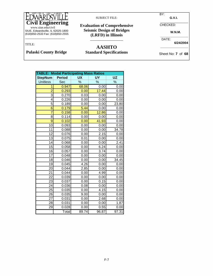
Civil Engineering www.siue.edu/civilSIUE, Edwardsville, IL 62025-1800(618)650-2533 Fax: (618)650-2555_______________________
TITLE:
Pulaski County Bridge
SUBJECT FILE:
Evaluation of Comprehensive Seismic Design of Bridges
(LRFD) in Illinois___________________
AASHTOStandard Specifications
BY: _________ G.V.I.______
________________CHECKED: _____
W.N.M.-------________________DATE:__________
6/24/2004________________
Sheet No: 7 of 68
TABLE: Modal Participating Mass RatiosStepNum Period UX UY UZUnitless Sec % % %
1 0.947 68.06 0.00 0.002 0.293 0.00 17.44 0.003 0.270 0.03 0.00 0.004 0.226 0.00 0.00 0.005 0.189 0.00 0.00 23.806 0.179 5.44 0.00 0.007 0.158 0.00 12.86 0.008 0.114 0.00 0.00 0.009 0.102 0.00 41.93 0.00
10 0.093 0.00 0.00 0.0011 0.088 0.00 0.00 34.7812 0.076 0.00 2.15 0.0013 0.075 0.01 0.00 0.0014 0.068 0.00 0.00 2.4115 0.058 0.00 6.24 0.0016 0.057 0.00 3.74 0.0017 0.048 0.00 0.00 0.0018 0.046 0.00 0.00 34.4519 0.045 4.26 0.00 0.0020 0.044 2.85 0.00 0.0021 0.044 0.00 4.99 0.0022 0.039 0.00 0.00 0.0023 0.037 0.00 0.15 0.0024 0.036 0.08 0.00 0.0025 0.035 0.00 4.15 0.0026 0.035 9.00 0.00 0.0027 0.031 0.00 2.68 0.0028 0.031 0.00 0.00 1.8729 0.028 0.00 0.55 0.00
Total 89.74 96.87 97.31
F-7

Civil Engineering www.siue.edu/civilSIUE, Edwardsville, IL 62025-1800(618)650-2533 Fax: (618)650-2555_______________________
TITLE:
Pulaski County Bridge
SUBJECT FILE:
Evaluation of Comprehensive Seismic Design of Bridges
(LRFD) in Illinois___________________
AASHTOStandard Specifications
BY: _________ G.V.I.______
________________CHECKED: _____
W.N.M.-------________________DATE:__________
6/24/2004________________
Sheet No: 8 of 68
Response Spectrum
0.00
0.300.30
0.650.70
0.800.90
1.00
1.25
1.50
2.50 2.75 3.00
0.30 0.60
1.75 2.00 2.25
0.00
0.05
0.10
0.15
0.20
0.25
0.30
0.35
0.40
0.45
0.50
0.55
0.60
0.0 0.5 1.0 1.5 2.0 2.5 3.0 3.5
Period, Tm(seconds)
Res
pons
e Sp
ectra
l Acc
eler
atio
n, C
s(fra
ctio
n of
g) Division 1-A
Pulaski County Bridge - AASHTO Division 1-A Tm Cs
0.000 0.1760.300 0.4400.300 0.4400.300 0.5500.300 0.5500.611 0.5500.600 0.5500.650 0.5280.700 0.5020.800 0.4600.900 0.4251.000 0.3961.250 0.3411.500 0.3021.750 0.2732.000 0.2492.250 0.2312.500 0.2152.750 0.2023.000 0.190
Earthquake Data:
Seismic Performance Category (SPC) - C
Bedrock Acceleration Coefficient (A) - 0.22*g A 0.22:=
Soil Profile Type - III
Site Coefficient (S) - 1.5 Sc 1.5:=
F-8

Civil Engineering www.siue.edu/civilSIUE, Edwardsville, IL 62025-1800(618)650-2533 Fax: (618)650-2555_______________________
TITLE:
Pulaski County Bridge
SUBJECT FILE:
Evaluation of Comprehensive Seismic Design of Bridges
(LRFD) in Illinois___________________
AASHTOStandard Specifications
BY: _________ G.V.I.______
________________CHECKED: _____
W.N.M.-------________________DATE:__________
6/24/2004________________
Sheet No: 9 of 68
Load Combinations
COMB1 - 100% load in X (longitudinal) direction + 30% load in Y (transverse) direction
COMB2 - 100% load in Y (transverse) direction + 30% load in X (longitudinal) direction
COMD1 - COMB1 + Dead Load
COMD2 - COMB2 + Dead Load
F-9

Civil Engineering www.siue.edu/civilSIUE, Edwardsville, IL 62025-1800(618)650-2533 Fax: (618)650-2555_______________________
TITLE:
Pulaski County Bridge
SUBJECT FILE:
Evaluation of Comprehensive Seismic Design of Bridges
(LRFD) in Illinois___________________
AASHTOStandard Specifications
BY: _________ G.V.I.______
________________CHECKED: _____
W.N.M.-------________________DATE:__________
6/24/2004________________
Sheet No: 10 of 68
Piles (L-pile results)
Longitudinal direction of the bridge: (expansion pier)
F-10

Civil Engineering www.siue.edu/civilSIUE, Edwardsville, IL 62025-1800(618)650-2533 Fax: (618)650-2555_______________________
TITLE:
Pulaski County Bridge
SUBJECT FILE:
Evaluation of Comprehensive Seismic Design of Bridges
(LRFD) in Illinois___________________
AASHTOStandard Specifications
BY: _________ G.V.I.______
________________CHECKED: _____
W.N.M.-------________________DATE:__________
6/24/2004________________
Sheet No: 11 of 68
Transverse direction of the bridge: (expansion pier)
F-11

Civil Engineering www.siue.edu/civilSIUE, Edwardsville, IL 62025-1800(618)650-2533 Fax: (618)650-2555_______________________
TITLE:
Pulaski County Bridge
SUBJECT FILE:
Evaluation of Comprehensive Seismic Design of Bridges
(LRFD) in Illinois___________________
AASHTOStandard Specifications
BY: _________ G.V.I.______
________________CHECKED: _____
W.N.M.-------________________DATE:__________
6/24/2004________________
Sheet No: 12 of 68
Longitudinal direction of the bridge: (fixed pier)
F-12
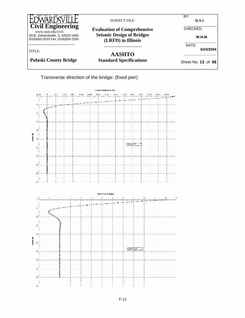
Civil Engineering www.siue.edu/civilSIUE, Edwardsville, IL 62025-1800(618)650-2533 Fax: (618)650-2555_______________________
TITLE:
Pulaski County Bridge
SUBJECT FILE:
Evaluation of Comprehensive Seismic Design of Bridges
(LRFD) in Illinois___________________
AASHTOStandard Specifications
BY: _________ G.V.I.______
________________CHECKED: _____
W.N.M.-------________________DATE:__________
6/24/2004________________
Sheet No: 13 of 68
Transverse direction of the bridge: (fixed pier)
F-13

Civil Engineering www.siue.edu/civilSIUE, Edwardsville, IL 62025-1800(618)650-2533 Fax: (618)650-2555_______________________
TITLE:
Pulaski County Bridge
SUBJECT FILE:
Evaluation of Comprehensive Seismic Design of Bridges
(LRFD) in Illinois___________________
AASHTOStandard Specifications
BY: _________ G.V.I.______
________________CHECKED: _____
W.N.M.-------________________DATE:__________
6/24/2004________________
Sheet No: 14 of 68
- Distance between piles (on center)Set Db.pile equal to 6 ft
8 ft.-no larger than:
inDb.pile 70=
Db.pile 5 dpile⋅:=
In order to avoid a group effect in the foundation the distance between piles must be:- no less than:
Diameter of HP 14x89 pileindpile 14:=
Group effect
Pile CapacitykipQpile 352.35=Qpile 9 Apile⋅ 1.5⋅:=
Cross sectional area of HP14x89 pilein2Apile 26.1:=
Pile Capacity:
F-14

Civil Engineering www.siue.edu/civilSIUE, Edwardsville, IL 62025-1800(618)650-2533 Fax: (618)650-2555_______________________
TITLE:
Pulaski County Bridge
SUBJECT FILE:
Evaluation of Comprehensive Seismic Design of Bridges
(LRFD) in Illinois___________________
AASHTOStandard Specifications
BY: _________ G.V.I.______
________________CHECKED: _____
W.N.M.-------________________DATE:__________
6/24/2004________________
Sheet No: 15 of 68
ftW 8.5:=
ftL 26.5:=
Transverse (factored)k ft−Mx 646=MxMxunf.
R:=
Longitudinal (factored)k ft−My 480.1=MyMyunf.
R:=
Axial loadkipsP 516.1:=
Transverse (unfactored)k ft−Myunf. 480.1:=
Longitudinal (unfactored)k ft−Mxunf. 646.0:=
Load Combination COMD1
Response Modification Factor (applied in both directions)R 1:=
Skew of the bridgedegreesφ 0:=
Pier #1 & #3 (expansion)
Axial force on a pile.
F-15

Civil Engineering www.siue.edu/civilSIUE, Edwardsville, IL 62025-1800(618)650-2533 Fax: (618)650-2555_______________________
TITLE:
Pulaski County Bridge
SUBJECT FILE:
Evaluation of Comprehensive Seismic Design of Bridges
(LRFD) in Illinois___________________
AASHTOStandard Specifications
BY: _________ G.V.I.______
________________CHECKED: _____
W.N.M.-------________________DATE:__________
6/24/2004________________
Sheet No: 16 of 68
Pile Capacity is 352.35 kips
kipsFpile10 24.84=Fpile10P10
Myn3Σd1⋅− Mx
d1Σd2⋅−:=
kipsFpile6 46.37=Fpile6P10
Myn3Σd1⋅− Mx
d1Σd2⋅+:=
kipsFpile5 56.85=Fpile5P10
Myn3Σd1⋅+ Mx
d1Σd2⋅−:=
kipsFpile1 78.4=Fpile1P10
Myn3Σd1⋅+ Mx
d1Σd2⋅+:=
Piles Loads:
(transverse) ft2Σd2 720=Σd2 4 d22⎛
⎝⎞⎠⋅ 4 d1
2⎛⎝
⎞⎠⋅+:=
(longitudinal) ft2Σd1 90=Σd1 10 n32⎛
⎝⎞⎠⋅:=
Sum of squares of the distances to each pile from the center line of the foundation:
n3 3:=d3 0:=d2 6:=d1 12:=
The distance from center line of foundation to center of pile (ft): Distance between piles is set to avoid group effect
F-16

Civil Engineering www.siue.edu/civilSIUE, Edwardsville, IL 62025-1800(618)650-2533 Fax: (618)650-2555_______________________
TITLE:
Pulaski County Bridge
SUBJECT FILE:
Evaluation of Comprehensive Seismic Design of Bridges
(LRFD) in Illinois___________________
AASHTOStandard Specifications
BY: _________ G.V.I.______
________________CHECKED: _____
W.N.M.-------________________DATE:__________
6/24/2004________________
Sheet No: 17 of 68
Sum of squares of the distances to each pile from the center line of the foundation:
Σd1 10 n32⎛
⎝⎞⎠⋅:= Σd1 90= ft2 (longitudinal)
Σd2 4 d22⎛
⎝⎞⎠⋅ 4 d1
2⎛⎝
⎞⎠⋅+:= Σd2 720= ft2 (transverse)
Piles Loads:
Fpile1P10
Myn3Σd1⋅+ Mx
d1Σd2⋅+:= Fpile1 91.1= kips
Fpile5P10
Myn3Σd1⋅+ Mx
d1Σd2⋅−:= Fpile5 19.33= kips
Fpile6P10
Myn3Σd1⋅− Mx
d1Σd2⋅+:= Fpile6 81.51= kips
Fpile10P10
Myn3Σd1⋅− Mx
d1Σd2⋅−:= Fpile10 9.73= kips
Capacity is 352.35 kips
Load Combination COMD2
Mxunf. 2153.4:= k ft− Longitudinal (unfactored)
Myunf. 144.0:= k ft− Transverse (unfactored)
P 504.2:= kips Axial load
MyMyunf.
R:= My 144= k ft− Longitudinal (factored)
MxMxunf.
R:= Mx 2.153 103×= k ft− Transverse (factored)
The distance from center line of foundation to center of pile (ft): Distance between piles is set to avoid group effect
d1 12:= d2 6:= d3 0:= n3 3:=
F-17

Civil Engineering www.siue.edu/civilSIUE, Edwardsville, IL 62025-1800(618)650-2533 Fax: (618)650-2555_______________________
TITLE:
Pulaski County Bridge
SUBJECT FILE:
Evaluation of Comprehensive Seismic Design of Bridges
(LRFD) in Illinois___________________
AASHTOStandard Specifications
BY: _________ G.V.I.______
________________CHECKED: _____
W.N.M.-------________________DATE:__________
6/24/2004________________
Sheet No: 18 of 68
ftW 14.5:=
ftL 27:=
Transverse (factored)k ft−Mx 1.108 103×=MxMxunf.
R:=
Longitudinal (factored)k ft−My 1.178 104×=MyMyunf.
R:=
Axial loadkipsP 646.9:=
Transverse (unfactored)k ft−Myunf. 11784.1:=
Longitudinal (unfactored)k ft−Mxunf. 1108.4:=
Load Combination COMD1 (from SAP 2000; file: (FINAL) springs4
Response Modification Factor (applied in both directions)R 1:=
Skew of the bridgedegreesφ 0:=
Pier #2 (fixed)
Axial Force on a Pile.
F-18

Civil Engineering www.siue.edu/civilSIUE, Edwardsville, IL 62025-1800(618)650-2533 Fax: (618)650-2555_______________________
TITLE:
Pulaski County Bridge
SUBJECT FILE:
Evaluation of Comprehensive Seismic Design of Bridges
(LRFD) in Illinois___________________
AASHTOStandard Specifications
BY: _________ G.V.I.______
________________CHECKED: _____
W.N.M.-------________________DATE:__________
6/24/2004________________
Sheet No: 19 of 68
Fpile5 248.78= kips
Fpile11P10
Myn3Σd1⋅− Mx
d1Σd2⋅+:= Fpile11 119.4−= kips
Fpile15P10
Myn3Σd1⋅− Mx
d1Σd2⋅−:= Fpile15 144.027−= kips
Pile Capacity is 352.35 kips
Fpile3Fpile1 Fpile5+( )
2:= Fpile3 261.092= kips
Fpile2Fpile3 Fpile1+( )
2:= Fpile2 267.249= kips
Fpile4Fpile3 Fpile5+( )
2:= Fpile4 254.934= kips
The distance from center line of foundation to center of pile (ft):Distance between piles is set to avoid group effect
d1 12:= d2 6:= d3 0:= n3 6:=
Sum of squares of the distances to each pile from the center line of the foundation:
Σd1 10 n32⎛
⎝⎞⎠⋅:= Σd1 360= ft2 (longitudinal)
Σd2 720=Σd2 6 d2
2⎛⎝
⎞⎠⋅ 6 d1
2⎛⎝
⎞⎠⋅+:= ft2 (transverse)
Piles Loads:
Fpile1P10
Myn3Σd1⋅+ Mx
d1Σd2⋅+:= Fpile1 273.4= kips
Fpile5P10
Myn3Σd1⋅+ Mx
d1Σd2⋅−:=
F-19

Civil Engineering www.siue.edu/civilSIUE, Edwardsville, IL 62025-1800(618)650-2533 Fax: (618)650-2555_______________________
TITLE:
Pulaski County Bridge
SUBJECT FILE:
Evaluation of Comprehensive Seismic Design of Bridges
(LRFD) in Illinois___________________
AASHTOStandard Specifications
BY: _________ G.V.I.______
________________CHECKED: _____
W.N.M.-------________________DATE:__________
6/24/2004________________
Sheet No: 20 of 68
Sum of squares of the distances to each pile from the center line of the foundation:
Σd1 10 n32⎛
⎝⎞⎠⋅:= Σd1 360= ft2 (longitudinal)
Σd2 6 d22⎛
⎝⎞⎠⋅ 6 d1
2⎛⎝
⎞⎠⋅+:= Σd2 1.08 103×= ft2 (transverse)
Piles Loads:
Fpile1P10
Myn3Σd1⋅+ Mx
d1Σd2⋅+:= Fpile1 164.7= kips
Fpile5P10
Myn3Σd1⋅+ Mx
d1Σd2⋅−:= Fpile5 82.56= kips
Fpile11P10
Myn3Σd1⋅− Mx
d1Σd2⋅+:= Fpile11 46.82= kips
Fpile15P10
Myn3Σd1⋅− Mx
d1Σd2⋅−:= Fpile15 35.282−= kips
Pile Capacity is 352.35 kips
Load Combination COMD2 (from SAP 2000; file: (FINAL) springs4
Mxunf. 3694.7:= k ft− Longitudinal (unfactored)
Myunf. 3535.2:= k ft− Transverse (unfactored)
P 646.9:= kips Axial load
MyMyunf.
R:= My 3.535 103×= k ft− Longitudinal (factored)
MxMxunf.
R:= Mx 3.695 103×= k ft− Transverse (factored)
The distance from center line of foundation to center of pile (ft): Distance between piles is set to avoid group effect
d1 12:= d2 6:= d3 0:= n3 6:=
F-20

Civil Engineering www.siue.edu/civilSIUE, Edwardsville, IL 62025-1800(618)650-2533 Fax: (618)650-2555_______________________
TITLE:
Pulaski County Bridge
SUBJECT FILE:
Evaluation of Comprehensive Seismic Design of Bridges
(LRFD) in Illinois___________________
AASHTOStandard Specifications
BY: _________ G.V.I.______
________________CHECKED: _____
W.N.M.-------________________DATE:__________
6/24/2004________________
Sheet No: 21 of 68
full plastic moment about Y-axis (longitudinal)k in⋅Mpy 5.256 103×=
Mpy Fy Zy⋅:=
full plastic moment about X-axis (transverse) k in⋅Mpx 2.437 103×=
Mpx Fy Zx⋅:=
in3Zy 146.0:=
in3Zx 67.7:=
in2Apile 26.1:=
ksiFy 36:= All axes are Global to SAP 2000 model e.g.. designation "longitudinal" and "transverse" refer to location of Global coordinate system in SAP model.
HP 14x89 pile properties:
Combined axial load and bending (AASHTO sixteenth edition):(Article 10.54.2.1 Maximum Capacity; equation 10-156, p.330)
F-21

Civil Engineering www.siue.edu/civilSIUE, Edwardsville, IL 62025-1800(618)650-2533 Fax: (618)650-2555_______________________
TITLE:
Pulaski County Bridge
SUBJECT FILE:
Evaluation of Comprehensive Seismic Design of Bridges
(LRFD) in Illinois___________________
AASHTOStandard Specifications
BY: _________ G.V.I.______
________________CHECKED: _____
W.N.M.-------________________DATE:__________
6/24/2004________________
Sheet No: 22 of 68
P0.85 Apile⋅ Fy⋅
⎛⎜⎝
⎞
⎠
MxLpileMpx
⎛⎜⎜⎝
⎞
⎠
MyLpileMpy
⎛⎜⎜⎝
⎞
⎠+
⎡⎢⎢⎣
⎤⎥⎥⎦
+ 0.128=In order to satisfy AASHTO designrequirements the resultant of thisequation must be less than or equal 1.
Response Modification Factor for piles (SPC - C)Rp 1:=
moment about Y-axis (single pile)k in⋅MyLpile 84.0:=
moment about X-axis(single pile)k in⋅MxLpile 32.7:=
Maximum Loads (from LPILE output):
axial load (single pile)kP 78.4:=
(as determined in "Axial force on a pile")
Maximum axial force on a pile:
Load combination: COMD 1
Pier #1 & #3 (expansion)
F-22

Civil Engineering www.siue.edu/civilSIUE, Edwardsville, IL 62025-1800(618)650-2533 Fax: (618)650-2555_______________________
TITLE:
Pulaski County Bridge
SUBJECT FILE:
Evaluation of Comprehensive Seismic Design of Bridges
(LRFD) in Illinois___________________
AASHTOStandard Specifications
BY: _________ G.V.I.______
________________CHECKED: _____
W.N.M.-------________________DATE:__________
6/24/2004________________
Sheet No: 23 of 68
P0.85 Apile⋅ Fy⋅
⎛⎜⎝
⎞
⎠
MxLpileMpx
⎛⎜⎜⎝
⎞
⎠
MyLpileMpy
⎛⎜⎜⎝
⎞
⎠+
⎡⎢⎢⎣
⎤⎥⎥⎦
+ 0.143=In order to satisfy AASHTO designrequirements the resultant of thisequation must be less than or equal 1.
Response Modification Factor for piles (SPC - C)Rp 1:=
moment about Y-axis (single pile)k in⋅MyLpile 84.0:=
moment about X-axis(single pile)k in⋅MxLpile 32.7:=
Maximum Loads (from LPILE output):
axial load (single pile)kP 91.1:=
(as determined in "Axial force on a pile")
Maximum axial force on a pile:
Load combination: COMD 2
Pier #1 & #3 (expansion)
F-23

Civil Engineering www.siue.edu/civilSIUE, Edwardsville, IL 62025-1800(618)650-2533 Fax: (618)650-2555_______________________
TITLE:
Pulaski County Bridge
SUBJECT FILE:
Evaluation of Comprehensive Seismic Design of Bridges
(LRFD) in Illinois___________________
AASHTOStandard Specifications
BY: _________ G.V.I.______
________________CHECKED: _____
W.N.M.-------________________DATE:__________
6/24/2004________________
Sheet No: 24 of 68
P0.85 Apile⋅ Fy⋅
⎛⎜⎝
⎞
⎠
MxLpileMpx
⎛⎜⎜⎝
⎞
⎠
MyLpileMpy
⎛⎜⎜⎝
⎞
⎠+
⎡⎢⎢⎣
⎤⎥⎥⎦
+ 0.474=In order to satisfy AASHTO designrequirements the resultant of thisequation must be less than or equal 1.
Response Modification Factor for piles (SPC - C)Rp 1:=
moment about Y-axis (single pile)k in⋅MyLpile 251.6:=
moment about X-axis(single pile)k in⋅MxLpile 205.4:=
Maximum Loads (from LPILE output):
axial load (single pile)kP 273.4:=
(as determined in "Axial force on a pile")
Maximum axial force on a pile:
Load combination: COMD 1
Pier #2 (fixed)
F-24

Civil Engineering www.siue.edu/civilSIUE, Edwardsville, IL 62025-1800(618)650-2533 Fax: (618)650-2555_______________________
TITLE:
Pulaski County Bridge
SUBJECT FILE:
Evaluation of Comprehensive Seismic Design of Bridges
(LRFD) in Illinois___________________
AASHTOStandard Specifications
BY: _________ G.V.I.______
________________CHECKED: _____
W.N.M.-------________________DATE:__________
6/24/2004________________
Sheet No: 25 of 68
P0.85 Apile⋅ Fy⋅
⎛⎜⎝
⎞
⎠
MxLpileMpx
⎛⎜⎜⎝
⎞
⎠
MyLpileMpy
⎛⎜⎜⎝
⎞
⎠+
⎡⎢⎢⎣
⎤⎥⎥⎦
+ 0.338=In order to satisfy AASHTO designrequirements the resultant of thisequation must be less than or equal 1.
Response Modification Factor for piles (SPC - C)Rp 1:=
moment about Y-axis (single pile)k in⋅MyLpile 251.6:=
moment about X-axis(single pile)k in⋅MxLpile 205.4:=
Maximum Loads (from LPILE output):
axial load (single pile)kP 164.7:=
(as determined in "Axial force on a pile")
Maximum axial force on a pile:
Load combination: COMD 2
Pier #2 (fixed)
F-25

Civil Engineering www.siue.edu/civilSIUE, Edwardsville, IL 62025-1800(618)650-2533 Fax: (618)650-2555_______________________
TITLE:
Pulaski County Bridge
SUBJECT FILE:
Evaluation of Comprehensive Seismic Design of Bridges
(LRFD) in Illinois___________________
AASHTOStandard Specifications
BY: _________ G.V.I.______
________________CHECKED: _____
W.N.M.-------________________DATE:__________
6/24/2004________________
Sheet No: 26 of 68
lb Transverse
Vulong 3712.2:= lb Longitudinal
Spring Stiffness (per one pile):
kaxial ApileEs
Lpile⋅:= kaxial 1.402 106×=
lbin
Axial
ktransVutrans
∆ t:= ktrans 9.322 105×=
lbin
Transverse
klongVulong∆ l
:= klong 1.237 106×=lbin
Longitudinal
SpringsPier #1 & #3 (expansion)
Pile Information for L-Pile input:
HP 14x89 - piles
Lpile 540:= in
Apile 26.1:= in2
Es 29000000:=lb
in2
Results from L-Pile:Piers #1 & #3 Long.HP 14x89_(iteration3).lpd Piers #1 & #3 Trans.HP 14x89_(iteration3).lpd
∆ t 0.002:= in Displacement (transverse)
∆ l 0.003:= in Displacement (longitudinal)
Vutrans 1864.3:=
F-26

Civil Engineering www.siue.edu/civilSIUE, Edwardsville, IL 62025-1800(618)650-2533 Fax: (618)650-2555_______________________
TITLE:
Pulaski County Bridge
SUBJECT FILE:
Evaluation of Comprehensive Seismic Design of Bridges
(LRFD) in Illinois___________________
AASHTOStandard Specifications
BY: _________ G.V.I.______
________________CHECKED: _____
W.N.M.-------________________DATE:__________
6/24/2004________________
Sheet No: 27 of 68
NOTE: Distance between piles is set to avoid group effect
Pier # 1 & # 3 (expantion)
Y
X
6 10
5
8 9
3
7
421
d2
d1
L
Wn3
n3 n1 n2
Ku3( )Along Z axislbin
Kaxial 1.402 107×=Kaxial 10 kaxial⋅:=
Axial Springs:
Ku2( )Along Y axislbin
Ktrans 9.322 106×=Ktrans 10 ktrans⋅:=
Ku1( )Along X axislbin
Klong 1.237 107×=Klong 10 klong⋅:=
Lateral Springs:
F-27
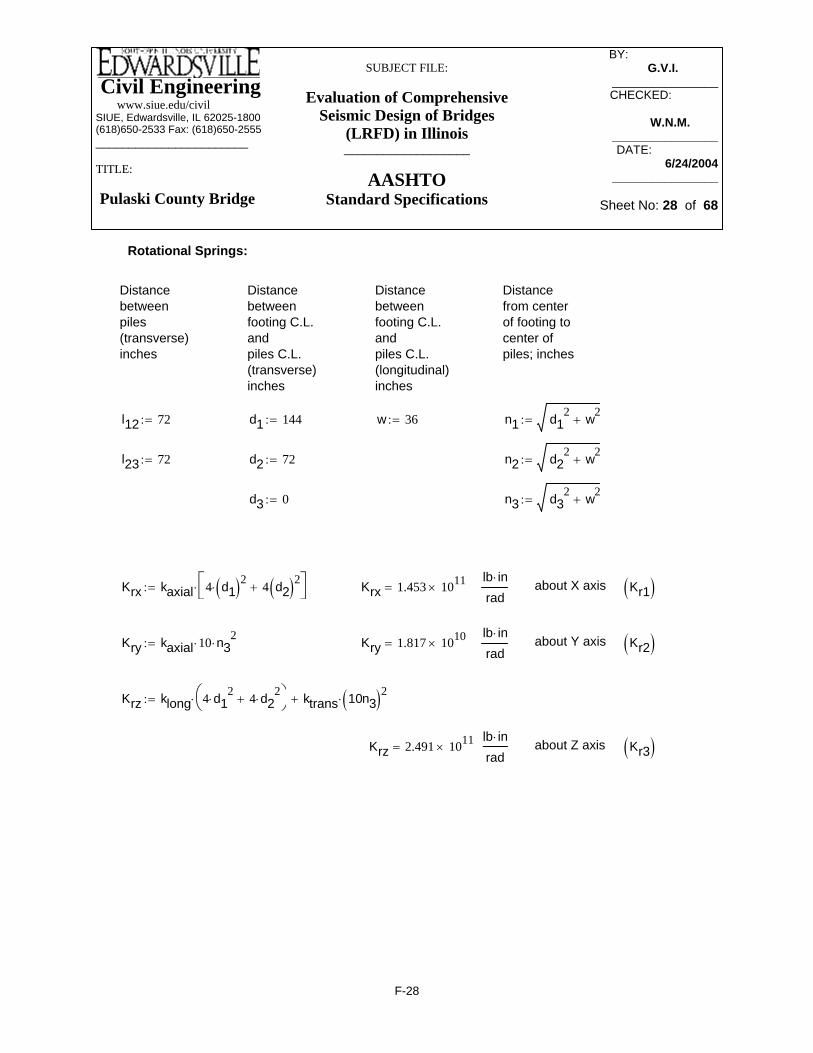
Civil Engineering www.siue.edu/civilSIUE, Edwardsville, IL 62025-1800(618)650-2533 Fax: (618)650-2555_______________________
TITLE:
Pulaski County Bridge
SUBJECT FILE:
Evaluation of Comprehensive Seismic Design of Bridges
(LRFD) in Illinois___________________
AASHTOStandard Specifications
BY: _________ G.V.I.______
________________CHECKED: _____
W.N.M.-------________________DATE:__________
6/24/2004________________
Sheet No: 28 of 68
Kr3( )about Z axislb in⋅rad
Krz 2.491 1011×=
Krz klong 4 d12
⋅ 4 d22
⋅+⎛⎝
⎞⎠⋅ ktrans 10n3( )2⋅+:=
Kr2( )about Y axislb in⋅rad
Kry 1.817 1010×=Kry kaxial 10⋅ n32
⋅:=
Kr1( )about X axislb in⋅rad
Krx 1.453 1011×=Krx kaxial 4 d1( )2⋅ 4 d2( )2+⎡⎣
⎤⎦⋅:=
n3 d32 w2+:=d3 0:=
n2 d22 w2+:=d2 72:=l23 72:=
n1 d12 w2+:=w 36:=d1 144:=l12 72:=
Distancefrom centerof footing tocenter ofpiles; inches
Distancebetweenfooting C.L.andpiles C.L.(longitudinal)inches
Distancebetweenfooting C.L.andpiles C.L.(transverse)inches
Distancebetweenpiles(transverse)inches
Rotational Springs:
F-28
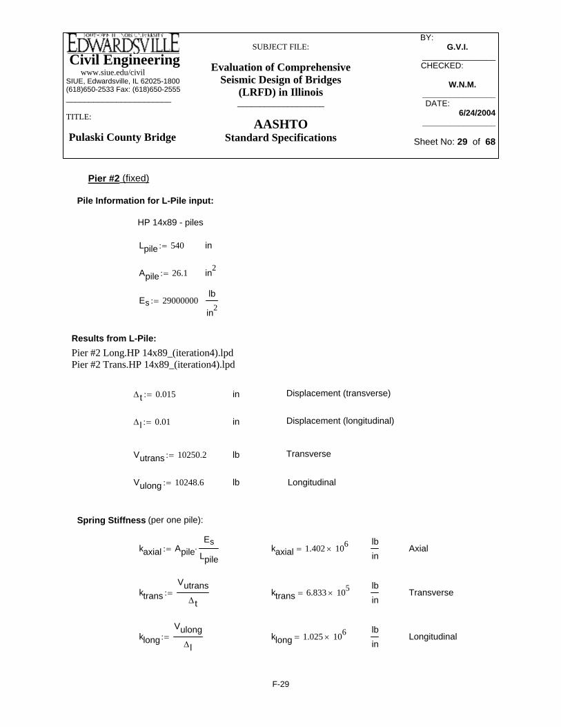
Civil Engineering www.siue.edu/civilSIUE, Edwardsville, IL 62025-1800(618)650-2533 Fax: (618)650-2555_______________________
TITLE:
Pulaski County Bridge
SUBJECT FILE:
Evaluation of Comprehensive Seismic Design of Bridges
(LRFD) in Illinois___________________
AASHTOStandard Specifications
BY: _________ G.V.I.______
________________CHECKED: _____
W.N.M.-------________________DATE:__________
6/24/2004________________
Sheet No: 29 of 68
lb Transverse
Vulong 10248.6:= lb Longitudinal
Spring Stiffness (per one pile):
kaxial ApileEs
Lpile⋅:= kaxial 1.402 106×=
lbin
Axial
ktransVutrans
∆ t:= ktrans 6.833 105×=
lbin
Transverse
klongVulong∆ l
:= klong 1.025 106×=lbin
Longitudinal
Pier #2 (fixed)
Pile Information for L-Pile input:
HP 14x89 - piles
Lpile 540:= in
Apile 26.1:= in2
Es 29000000:=lb
in2
Results from L-Pile:Pier #2 Long.HP 14x89_(iteration4).lpd Pier #2 Trans.HP 14x89_(iteration4).lpd
∆ t 0.015:= in Displacement (transverse)
∆ l 0.01:= in Displacement (longitudinal)
Vutrans 10250.2:=
F-29

Civil Engineering www.siue.edu/civilSIUE, Edwardsville, IL 62025-1800(618)650-2533 Fax: (618)650-2555_______________________
TITLE:
Pulaski County Bridge
SUBJECT FILE:
Evaluation of Comprehensive Seismic Design of Bridges
(LRFD) in Illinois___________________
AASHTOStandard Specifications
BY: _________ G.V.I.______
________________CHECKED: _____
W.N.M.-------________________DATE:__________
6/24/2004________________
Sheet No: 30 of 68
NOTE: Distance between piles is set to avoid group effect
Pier # 2 (fixed)X
YWn3
n3
11 12 13 14 15
6 7 8 9
1 2
10
3 54n1 n2
d2
d1
L
Ku3( )Along Z axislbin
Kaxial 2.103 107×=Kaxial 15 kaxial⋅:=
Axial Springs:
lbin
Ktrans 1.025 107×=Ktrans 15 ktrans⋅:=Ku2( )Along Y axis
Ku1( )Along X axislbin
Klong 1.537 107×=Klong 15 klong⋅:=
Lateral Springs:
F-30
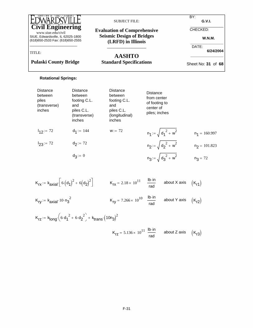
Civil Engineering www.siue.edu/civilSIUE, Edwardsville, IL 62025-1800(618)650-2533 Fax: (618)650-2555_______________________
TITLE:
Pulaski County Bridge
SUBJECT FILE:
Evaluation of Comprehensive Seismic Design of Bridges
(LRFD) in Illinois___________________
AASHTOStandard Specifications
BY: _________ G.V.I.______
________________CHECKED: _____
W.N.M.-------________________DATE:__________
6/24/2004________________
Sheet No: 31 of 68
Kr3( )about Z axislb in⋅rad
Krz 5.136 1011×=
Krz klong 6 d12
⋅ 6 d22
⋅+⎛⎝
⎞⎠⋅ ktrans 10n3( )2⋅+:=
Kr2( )about Y axislb in⋅rad
Kry 7.266 1010×=Kry kaxial 10⋅ n32
⋅:=
Kr1( )about X axislb in⋅rad
Krx 2.18 1011×=Krx kaxial 6 d1( )2⋅ 6 d2( )2+⎡⎣
⎤⎦⋅:=
n3 72=n3 d32 w2+:=
d3 0:=
n2 101.823=n2 d22 w2+:=
d2 72:=l23 72:=
n1 160.997=n1 d12 w2+:=
w 72:=d1 144:=l12 72:=
Distancefrom centerof footing tocenter ofpiles; inches
Distancebetweenfooting C.L.andpiles C.L.(longitudinal)inches
Distancebetweenfooting C.L.andpiles C.L.(transverse)inches
Distancebetweenpiles(transverse)inches
Rotational Springs:
F-31

Civil Engineering www.siue.edu/civilSIUE, Edwardsville, IL 62025-1800(618)650-2533 Fax: (618)650-2555_______________________
TITLE:
Pulaski County Bridge
SUBJECT FILE:
Evaluation of Comprehensive Seismic Design of Bridges
(LRFD) in Illinois___________________
AASHTOStandard Specifications
BY: _________ G.V.I.______
________________CHECKED: _____
W.N.M.-------________________DATE:__________
6/24/2004________________
Sheet No: 32 of 68
Displacements at bottom of foundation
SAP 2000 File: (FINAL)springs5TABLE: Joint Displacements
Joint OutputCase U1 U2 U3 R1 R2 R3Text Text in in in Radians Radians Radians
66 DEAD 0.000 0.000 -0.036 0.000 0.000 0.000COMD1 0.003 0.002 -0.034 0.000 0.000 0.000COMD2 0.001 0.007 -0.035 0.000 0.000 0.000
70 DEAD 0.000 0.000 -0.036 0.000 0.000 0.000COMD1 0.003 0.002 -0.034 0.000 0.000 0.000COMD2 0.001 0.007 -0.035 0.000 0.000 0.000
74 DEAD 0.000 0.000 -0.031 0.000 0.000 0.000COMD1 0.032 0.004 -0.031 0.000 0.002 0.000COMD2 0.010 0.014 -0.031 0.000 0.001 0.000
Joint # 66- bottom of Pier # 1Joint # 70- bottom of Pier # 3Joint # 74- bottom of Pier # 2
Displacements are approximately equal to those obtained from LPILE:Files:Piers #1 & #3 Long.HP 14x89_(iteration3).lpd
Piers #1 & #3 Trans.HP 14x89_(iteration3).lpd
Pier #2 Long.HP 14x89_(iteration4).lpd
Pier #2 Trans.HP 14x89_(iteration4).lpd
F-32

Civil Engineering www.siue.edu/civilSIUE, Edwardsville, IL 62025-1800(618)650-2533 Fax: (618)650-2555_______________________
TITLE:
Pulaski County Bridge
SUBJECT FILE:
Evaluation of Comprehensive Seismic Design of Bridges
(LRFD) in Illinois___________________
AASHTOStandard Specifications
BY: _________ G.V.I.______
________________CHECKED: _____
W.N.M.-------________________DATE:__________
6/24/2004________________
Sheet No: 33 of 68
LPile output See Appendices for actual LPile output
Path to file locations: Z:\ITRC research\Pulaski C.B\Lpile\Design\Name of input data file: Piers #1 & #3 Long.HP 14x89_(iteration3).lpd
BC Boundary Boundary Axial Pile Head Maximum MaximumType Condition Condition Load Deflection Moment Shear 1 2 lbs in in-lbs lbs---- ------------ ------------ ----------- ----------- ----------- ----------- 5 y= .003000 S= 0.000 51597.0000 .003000 -84023.6868 3712.2222
Path to file locations: Z:\ITRC research\Pulaski C.B\Lpile\Design\Name of input data file: Piers #1 & #3 Trans.HP 14x89_(iteration3).lpd
BC Boundary Boundary Axial Pile Head Maximum MaximumType Condition Condition Load Deflection Moment Shear 1 2 lbs in in-lbs lbs---- ------------ ------------ ----------- ----------- ----------- ----------- 5 y= .002000 S= 0.000 51597.0000 .002000 -32745.3507 1864.3300
Path to file locations: Z:\ITRC research\Pulaski C.B\Lpile\Design\Name of input data file: Pier #2 Long.HP 14x89_(iteration4).lpd
BC Boundary Boundary Axial Pile Head Maximum MaximumType Condition Condition Load Deflection Moment Shear 1 2 lbs in in-lbs lbs---- ------------ ------------ ----------- ----------- ----------- ----------- 5 y= .010000 S= 0.000 43126.0000 .010000 -2.516E+05 10248.6469
Path to file locations: Z:\ITRC research\Pulaski C.B\Lpile\Design\Name of input data file: Pier #2 Trans.HP 14x89_(iteration4).lpd
BC Boundary Boundary Axial Pile Head Maximum MaximumType Condition Condition Load Deflection Moment Shear 1 2 lbs in in-lbs lbs---- ------------ ------------ ----------- ----------- ----------- ----------- 5 y= .015000 S= 0.000 43126.0000 .015000 -2.054E+05 10250.2109
F-33

Civil Engineering www.siue.edu/civilSIUE, Edwardsville, IL 62025-1800(618)650-2533 Fax: (618)650-2555_______________________
TITLE:
Pulaski County Bridge
SUBJECT FILE:
Evaluation of Comprehensive Seismic Design of Bridges
(LRFD) in Illinois___________________
AASHTOStandard Specifications
BY: _________ G.V.I.______
________________CHECKED: _____
W.N.M.-------________________DATE:__________
6/24/2004________________
Sheet No: 34 of 68
Forces in substructure
SAP 2000 model: (FINAL)springs4Without Response Modification FactorPulaski County (Pier #1 & #3 at neck Joints #4 & #40; at bottom Joints #5 and #30)TABLE: Element Joint Forces - Frames V2 V3 P M2 M3 M1
Frame FrameElem Joint OutputCase F1 F2 F3 M1 M2 M3Text Text Text Text Kip Kip Kip Kip-ft Kip-ft Kip-ft
33 8 4 DEAD 0.0 0.0 -352.2 0.0 0.0 0.0COMD1 21.0 16.4 -335.6 756.5 51.2 6.4COMD2 6.3 54.8 -347.2 2521.5 15.3 21.3
42 25 40 DEAD 0.0 0.0 -352.2 0.0 0.0 0.0COMD1 21.0 16.4 -335.6 756.5 51.2 6.4COMD2 6.3 54.8 -347.2 2521.5 15.3 21.3
45 28 5 DEAD 0.0 0.0 -423.1 0.0 0.0 0.0COMD1 31.7 18.0 -406.4 655.1 409.1 6.4COMD2 9.5 60.1 -418.1 2183.6 122.7 21.3
70 32 30 DEAD 0.0 0.0 -423.1 0.0 0.0 0.0COMD1 31.7 18.0 -406.4 655.1 409.1 6.4COMD2 9.5 60.1 -418.1 2183.6 122.7 21.3
Pulaski County (Pier #2 at neck Joint # 23; at bottom Joint #14)20 11 23 DEAD 0.0 0.0 427.6 0.0 0.0 0.0
COMD1 480.4 34.8 427.6 634.5 2613.0 0.0COMD2 144.1 116.1 427.6 2115.0 783.9 0.0
75 36 14 DEAD 0.0 0.0 -514.8 0.0 0.0 0.0COMD1 491.9 39.2 -514.8 1035.2 10676.9 0.0COMD2 147.6 130.7 -514.8 3450.6 3203.1 0.0
F-34

Civil Engineering www.siue.edu/civilSIUE, Edwardsville, IL 62025-1800(618)650-2533 Fax: (618)650-2555_______________________
TITLE:
Pulaski County Bridge
SUBJECT FILE:
Evaluation of Comprehensive Seismic Design of Bridges
(LRFD) in Illinois___________________
AASHTOStandard Specifications
BY: _________ G.V.I.______
________________CHECKED: _____
W.N.M.-------________________DATE:__________
6/24/2004________________
Sheet No: 35 of 68
With Response Modification FactorPulaski County (Pier #1 & #3 at neck Joints #4 & #40; at bottom Joints #5 and #30)TABLE: Element Joint Forces - Frames V2 V3 P M2 M3 M1
Frame FrameElem Joint OutputCase F1 F2 F3 M1 M2 M3Text Text Text Text Kip Kip Kip Kip-ft Kip-ft Kip-ft
33 8 4 DEAD 0.0 0.0 -352.2 0.0 0.0 0.0COMD1 21.0 16.4 -335.6 378.2 25.6 6.4COMD2 6.3 54.8 -347.2 1260.8 7.7 21.3
0.0 0.042 25 40 DEAD 0.0 0.0 -352.2 0.0 0.0 0.0
COMD1 21.0 16.4 -335.6 378.2 25.6 6.4COMD2 6.3 54.8 -347.2 1260.8 7.7 21.3
0.0 0.045 28 5 DEAD 0.0 0.0 -423.1 0.0 0.0 0.0
COMD1 31.7 18.0 -406.4 327.5 204.5 6.4COMD2 9.5 60.1 -418.1 1091.8 61.4 21.3
0 070 32 30 DEAD 0.0 0.0 -423.1 0.0 0.0 0.0
COMD1 31.7 18.0 -406.4 327.5 204.5 6.4COMD2 9.5 60.1 -418.1 1091.8 61.4 21.3
Pulaski County (Pier #2 at neck Joint # 23; at bottom Joint #14)20 11 23 DEAD 0.0 0.0 427.6 0.0 0.0 0.0
COMD1 480.4 34.8 427.6 317.2 1306.5 0.0COMD2 144.1 116.1 427.6 1057.5 392.0 0.0
0.0 0.075 36 14 DEAD 0.0 0.0 -514.8 0.0 0.0 0.0
COMD1 491.9 39.2 -514.8 517.6 5338.5 0.0COMD2 147.6 130.7 -514.8 1725.3 1601.5 0.0
Response Modification Factors:Piers:R=1 ShearR=2 FlexurePiles:R=1 longitudinal and transverse
F-35

Civil Engineering www.siue.edu/civilSIUE, Edwardsville, IL 62025-1800(618)650-2533 Fax: (618)650-2555_______________________
TITLE:
Pulaski County Bridge
SUBJECT FILE:
Evaluation of Comprehensive Seismic Design of Bridges
(LRFD) in Illinois___________________
AASHTOStandard Specifications
BY: _________ G.V.I.______
________________CHECKED: _____
W.N.M.-------________________DATE:__________
6/24/2004________________
Sheet No: 36 of 68
Spring Forces
SAP 2000 File: (FINAL)springs4TABLE: Joint Reactions - Spring Forces
Joint OutputCase U1 U2 U3 R1 R2 R3Text Text Kip Kip Kip Kip-ft Kip-ft Kip-ft
66 DEAD 0.0 0.0 499.1 0.0 0.0 0.0COMD1 36.1 19.4 516.1 646.0 480.1 6.4COMD2 10.8 64.6 504.2 2153.4 144.0 21.3
70 DEAD 0.0 0.0 499.1 0.0 0.0 0.0COMD1 36.1 19.4 516.1 646.0 480.1 6.4COMD2 10.8 64.6 504.2 2153.4 144.0 21.3
74 DEAD 0.0 0.0 646.9 0.0 0.0 0.0COMD1 493.2 42.2 646.9 1108.4 11784.1 0.0COMD2 148.0 140.8 646.9 3694.7 3535.2 0.0
Joint # 66- bottom of Pier # 1Joint # 70- bottom of Pier # 3Joint # 74- bottom of Pier # 2
F-36

Civil Engineering www.siue.edu/civilSIUE, Edwardsville, IL 62025-1800(618)650-2533 Fax: (618)650-2555_______________________
TITLE:
Pulaski County Bridge
SUBJECT FILE:
Evaluation of Comprehensive Seismic Design of Bridges
(LRFD) in Illinois___________________
AASHTOStandard Specifications
BY: _________ G.V.I.______
________________CHECKED: _____
W.N.M.-------________________DATE:__________
6/24/2004________________
Sheet No: 37 of 68
factored MMun
R:=
R 2:=
unfactoredk ft−Mun 2183.6:=
kV 60.1:=
(for shear)Φ 0.85:=
-Hight of beamftl 18.25:=
-Distance from reinforcement to extreme compression fiberftd 14.725=
assumed( )d 0.95 h⋅:=
-Width of beamftb 2.5:=
-Depth of beamfth 15.5:=
psify 60000:=
psifc 3500:=
Shear design for pier #1& #3 (expansion)
Deep beam design (Reinforcement concrete, Nawy, 4rd edition, section 6.9)
Load Combination COMD2
Design checks for Pier # 1 and # 3 (expantion)
F-37

Civil Engineering www.siue.edu/civilSIUE, Edwardsville, IL 62025-1800(618)650-2533 Fax: (618)650-2555_______________________
TITLE:
Pulaski County Bridge
SUBJECT FILE:
Evaluation of Comprehensive Seismic Design of Bridges
(LRFD) in Illinois___________________
AASHTOStandard Specifications
BY: _________ G.V.I.______
________________CHECKED: _____
W.N.M.-------________________DATE:__________
6/24/2004________________
Sheet No: 38 of 68
-Nominal shear resisting force (controls)
Vcmax 6 fc⋅ b⋅ d⋅1441000⋅:=
Vcmax 1.882 103×= k -Maximum nominal shear resisting force
Φ Vc⋅ 533.139= k
Vu 2.133 103×= must be less or equal than Φ Vc Vs+( )⋅
Φ Vc⋅ < Vu -Shear reinforcement is required
Vu Φ Vc⋅− Φ Vs⋅≤
VsVuΦ
Vc−:=
Vs 1.882 103×= k
ld
1.239= < 2.5 - criteria determining Deep Beam
Forld
< 2.0 - use following eq.
Vu Φ 8 fc⋅ b⋅ d⋅( )⋅1441000⋅:=
Vu 2.133 103×= k -Factored shear force
V 60.1= k < Vu 2.133 103×= k OK
Vc 2 fc( )⋅ b⋅ d⋅1441000⋅:=
Vc 627.223= k
F-38

Civil Engineering www.siue.edu/civilSIUE, Edwardsville, IL 62025-1800(618)650-2533 Fax: (618)650-2555_______________________
TITLE:
Pulaski County Bridge
SUBJECT FILE:
Evaluation of Comprehensive Seismic Design of Bridges
(LRFD) in Illinois___________________
AASHTOStandard Specifications
BY: _________ G.V.I.______
________________CHECKED: _____
W.N.M.-------________________DATE:__________
6/24/2004________________
Sheet No: 39 of 68
-Maximum distance between rebarsin transverse direction (on center)
or 1.5 ft -use this value
sh 1.5:= ft -Distance between horizontal (transverse) rebars (on center)
tr 10.44:= in -Clear spacing between rebars;
tr 1.56+( )12
1=
sv 1.0:= ft -Distance between vertical rebars (on center);PCACOL (file:#11BOT13)
Atrsh
⎛⎜⎜⎝
⎞
⎠
1hd
⎛⎜⎝
⎞⎠
+⎡⎢⎣
⎤⎥⎦
12⋅
⎡⎢⎢⎢⎣
⎤⎥⎥⎥⎦
Alsv
⎛⎜⎜⎝
⎞
⎠
11hd
⎛⎜⎝
⎞⎠
−⎡⎢⎣
⎤⎥⎦
12⋅
⎡⎢⎢⎢⎣
⎤⎥⎥⎥⎦
fy⋅ d⋅+ Vs=
K1Atrsh
⎛⎜⎜⎝
⎞
⎠
1hd
⎛⎜⎝
⎞⎠
+⎡⎢⎣
⎤⎥⎦
12⋅:= K1 6.969 10 4−×=
K2Alsv
⎛⎜⎜⎝
⎞
⎠
11hd
⎛⎜⎝
⎞⎠
−⎡⎢⎣
⎤⎥⎦
12⋅:= K2 0.018=
As1 1.56:= in2 Cross sectional area of # 11 rebar
Al As12
144⋅:= Al 0.022= ft2 Area of trans. rebars placed at distance str
Astr 0.44:= in2 Cross sectional area of # 6 rebar
Atr Astr2
144⋅:= Atr 6.111 10 3−×= ft2 Area of long. rebars placed at distance sl
strmaxd5
:= strmax 2.945= ft
F-39
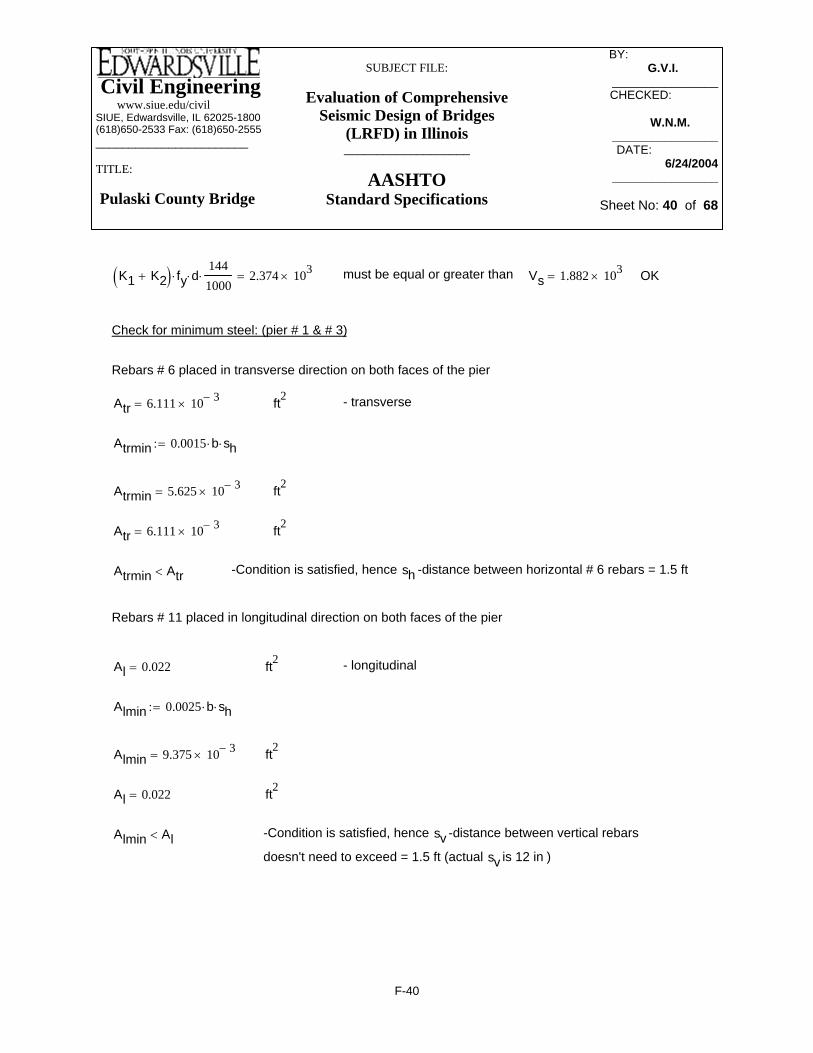
Civil Engineering www.siue.edu/civilSIUE, Edwardsville, IL 62025-1800(618)650-2533 Fax: (618)650-2555_______________________
TITLE:
Pulaski County Bridge
SUBJECT FILE:
Evaluation of Comprehensive Seismic Design of Bridges
(LRFD) in Illinois___________________
AASHTOStandard Specifications
BY: _________ G.V.I.______
________________CHECKED: _____
W.N.M.-------________________DATE:__________
6/24/2004________________
Sheet No: 40 of 68
-Condition is satisfied, hence sv -distance between vertical rebars
doesn't need to exceed = 1.5 ft (actual sv is 12 in )
Almin Al<
ft2Al 0.022=
ft2Almin 9.375 10 3−×=
Almin 0.0025 b⋅ sh⋅:=
- longitudinal ft2Al 0.022=
Rebars # 11 placed in longitudinal direction on both faces of the pier
-Condition is satisfied, hence sh -distance between horizontal # 6 rebars = 1.5 ftAtrmin Atr<
ft2Atr 6.111 10 3−×=
ft2Atrmin 5.625 10 3−×=
Atrmin 0.0015 b⋅ sh⋅:=
- transverse ft2Atr 6.111 10 3−×=
Rebars # 6 placed in transverse direction on both faces of the pier
Check for minimum steel: (pier # 1 & # 3)
OKVs 1.882 103×=must be equal or greater thanK1 K2+( ) fy⋅ d⋅1441000⋅ 2.374 103×=
F-40

Civil Engineering www.siue.edu/civilSIUE, Edwardsville, IL 62025-1800(618)650-2533 Fax: (618)650-2555_______________________
TITLE:
Pulaski County Bridge
SUBJECT FILE:
Evaluation of Comprehensive Seismic Design of Bridges
(LRFD) in Illinois___________________
AASHTOStandard Specifications
BY: _________ G.V.I.______
________________CHECKED: _____
W.N.M.-------________________DATE:__________
6/24/2004________________
Sheet No: 41 of 68
-number of rebars resisting tension (in transverse dir.) as acquired fromPCACOL design (file:#11BOT13)
ntr 7.925=
ntrysv
2⋅ 2+:=
ftsv 1=-Distance between vertical rebars (on center)as acquired from PCACOL design (file:#11TBOT13)
-Depth over which flex. reinf. is to be distributed (in transverse direction) fty 2.963=
y 0.25 h⋅ 0.05 l⋅−:=
-controls in2Asmin2 17.67=Asmin2 200 b⋅d 144⋅
fy⋅:=
in2Asmin1 15.681=Asmin1 max 3fc
fy⋅ b⋅ d⋅ 144⋅
⎛⎜⎜⎝
⎞
⎠:=
in2As 2.053=As
M 144⋅
Φ fy⋅ j⋅ d⋅1441000⋅
:=
Minimum reinforcement area
ftj d⋅ 9.85=
j 0.669=
j .2l 2 h⋅+( )
d:=
> 1 so jd=0.2*(l+2h)lh
1.177=
k ft−M 1.092 103×=
- for flexureΦ 0.9:=
Flexure design for deep beam (pier # 1 & # 3)
F-41

Civil Engineering www.siue.edu/civilSIUE, Edwardsville, IL 62025-1800(618)650-2533 Fax: (618)650-2555_______________________
TITLE:
Pulaski County Bridge
SUBJECT FILE:
Evaluation of Comprehensive Seismic Design of Bridges
(LRFD) in Illinois___________________
AASHTOStandard Specifications
BY: _________ G.V.I.______
________________CHECKED: _____
W.N.M.-------________________DATE:__________
6/24/2004________________
Sheet No: 42 of 68
As1 1.56:= in2 -cross section area of # 11 rebar
As As1 ntr⋅:= As 12.363= in2 -Total cross section area of rebars available to resist flexure
As 12.363= in^2 must be equal or greater than Asmin2 17.67= in^2 not satisfactory
As1 1.56:= in2 -cross section area of #11 rebar
NreqAsmin2
As1:=
Nreq 11.327= -number of #11bars to be placed within distance y 2.963= ft from extreme tension fiber
F-42

Civil Engineering www.siue.edu/civilSIUE, Edwardsville, IL 62025-1800(618)650-2533 Fax: (618)650-2555_______________________
TITLE:
Pulaski County Bridge
SUBJECT FILE:
Evaluation of Comprehensive Seismic Design of Bridges
(LRFD) in Illinois___________________
AASHTOStandard Specifications
BY: _________ G.V.I.______
________________CHECKED: _____
W.N.M.-------________________DATE:__________
6/24/2004________________
Sheet No: 43 of 68
in
bpc 26.5 12⋅:= in - Length of pile cap
wpc 8.5 12⋅:= in - Width of pile cap
h 36:= in -Thickness of the pile cap
demb 12:= in -Depth of pile embedment
daver h 3− dbar8−:=
daver 32= in -Average depth of the footing slab (from top to bottom reinforcement)
φ 0.85:= - for shear
Φ 0.9:= - for flexure
Pile cap design Pier # 1 & # 3 (expansion)
fc 3500:= psi
fy 60000:= psi
Paxial 91.1:= k -Vertical force at top of most loaded pile
dbar8 1.0:= in -Diameter of # 8 bar
abar8 0.79:= in2 -Area of # 8 bar
abar11 1.56:= in2 - Area of #11 bar
dp 13.83:= in -Cross sectional dimensions of HP 14x89bf 14.695:=
F-43

Civil Engineering www.siue.edu/civilSIUE, Edwardsville, IL 62025-1800(618)650-2533 Fax: (618)650-2555_______________________
TITLE:
Pulaski County Bridge
SUBJECT FILE:
Evaluation of Comprehensive Seismic Design of Bridges
(LRFD) in Illinois___________________
AASHTOStandard Specifications
BY: _________ G.V.I.______
________________CHECKED: _____
W.N.M.-------________________DATE:__________
6/24/2004________________
Sheet No: 44 of 68
OK Vuφ
Vc.max<
kVuφ
107.176=
(controles) -Maximum nominal shear strengthkVc.max 1.401 103×=
Vc.max 4 fc⋅bo daver⋅
1000⋅:=
-Nominal shear strengthkVc2 1.912 106×=
Vc2 2α daver⋅
bo+
⎛⎜⎜⎝
⎞
⎠fc⋅ bo⋅ daver⋅:=
α 20:=
-Nominal shear strengthkVc1 2.019 106×=
Vc1 24βc
+⎛⎜⎝
⎞
⎠fc⋅ bo⋅ daver⋅:=
βc 1.063=
βcbfdp
:=
-Perimeter of critical cross sectioninbo 185.05=
bo dp daver+( ) 2⋅ bf daver+( ) 2⋅+:=
kVu 91.1=
Vu Paxial:=
Pile punching shear check:
F-44

Civil Engineering www.siue.edu/civilSIUE, Edwardsville, IL 62025-1800(618)650-2533 Fax: (618)650-2555_______________________
TITLE:
Pulaski County Bridge
SUBJECT FILE:
Evaluation of Comprehensive Seismic Design of Bridges
(LRFD) in Illinois___________________
AASHTOStandard Specifications
BY: _________ G.V.I.______
________________CHECKED: _____
W.N.M.-------________________DATE:__________
6/24/2004________________
Sheet No: 45 of 68
OKφ Vc⋅ Vu1>
kφ Vc⋅ 2.987 103×=
Vc 3.514 103×=
Vc 4 fc⋅ bo⋅daver1000
⋅:=
inbo 464=
- Perimeter of the failure planeinbo 2 15.5 2.5+( )⋅ 12⋅ daver+:=
kVu1 911=
Vu1 10Paxial:=
Two way shear check:
OKφ Vc1⋅ Vu>
kφ Vc1⋅ 1.023 103×=
Vc1 2 fc⋅ bpc⋅daver1000
⋅:=
kVu 455.5=
Vu 5Paxial:=
kPaxial 91.1=
One way shear check:
F-45

Civil Engineering www.siue.edu/civilSIUE, Edwardsville, IL 62025-1800(618)650-2533 Fax: (618)650-2555_______________________
TITLE:
Pulaski County Bridge
SUBJECT FILE:
Evaluation of Comprehensive Seismic Design of Bridges
(LRFD) in Illinois___________________
AASHTOStandard Specifications
BY: _________ G.V.I.______
________________CHECKED: _____
W.N.M.-------________________DATE:__________
6/24/2004________________
Sheet No: 46 of 68
in4Ig 8.684 105×=Igbpc daver
3⋅
12:=
psifr 443.706=fr 7.5 fc⋅:=
inyt 16=ytdaver
2:=
OKΦ Mn⋅ Mu>
lb in−Φ Mn⋅ 5.664 107×=
lb in−Mn 6.294 107×=
Mn Asmin fy⋅ davera2
−⎛⎜⎝
⎞⎠
⋅:=
Flexure bending design: (longitudinal direction;short bars)
Mu 5 Paxial( )⋅ 18⋅ 1000⋅:=
Mu 8.199 106×= lb in− Φ 0.9:=
Asmin200 bpc⋅ daver⋅( )
fy:=
Asmin 33.92= in2
a 0.25 daver⋅:= assumed( )
AsMu
Φ fy⋅ a⋅:=
As 18.979= in2
aAsmin fy⋅( )
0.85 fc⋅ bpc⋅:=
a 2.151= in
F-46

Civil Engineering www.siue.edu/civilSIUE, Edwardsville, IL 62025-1800(618)650-2533 Fax: (618)650-2555_______________________
TITLE:
Pulaski County Bridge
SUBJECT FILE:
Evaluation of Comprehensive Seismic Design of Bridges
(LRFD) in Illinois___________________
AASHTOStandard Specifications
BY: _________ G.V.I.______
________________CHECKED: _____
W.N.M.-------________________DATE:__________
6/24/2004________________
Sheet No: 47 of 68
Mcrfr Ig⋅
yt:=
Mcr 2.408 107×= lb in−
Φ Mn⋅ 5.664 107×= lb in−
1.2Mcr 2.89 107×= lb in−
Φ Mn⋅ 1.2Mcr> OK
NLAsminabar8
:=
NL 42.937= - Number of short bars Short Bars use: 43 # 8
F-47

Civil Engineering www.siue.edu/civilSIUE, Edwardsville, IL 62025-1800(618)650-2533 Fax: (618)650-2555_______________________
TITLE:
Pulaski County Bridge
SUBJECT FILE:
Evaluation of Comprehensive Seismic Design of Bridges
(LRFD) in Illinois___________________
AASHTOStandard Specifications
BY: _________ G.V.I.______
________________CHECKED: _____
W.N.M.-------________________DATE:__________
6/24/2004________________
Sheet No: 48 of 68
in
Mn 40 fy⋅ davera2
−⎛⎜⎝
⎞⎠
⋅:=
Mn 7.17 107×= lb in−
Φ Mn⋅ 6.453 107×= lb in−
Φ Mn⋅ Mu> OK
ytdaver
2:= yt 16= in
fr 7.5 fc⋅:= fr 443.706= psi
Igbpc daver
3⋅
12:= Ig 8.684 105×= in4
Flexure bending design: (transverse direction; long bars)
Mu 2 Paxial⋅ 4.25⋅ 12⋅ 1000⋅:=
Mu 9.292 106×= lb in− Φ 0.9:=
Asmin200 wpc⋅ daver⋅( )
fy:=
Asmin 10.88= in2
a 0.25 daver⋅:= assumed( )
AsMu
Φ fy⋅ a⋅:=
As 21.51= in2 governs−
aAs fy⋅( )
0.85 fc⋅ wpc⋅:=
a 4.253=
F-48

Civil Engineering www.siue.edu/civilSIUE, Edwardsville, IL 62025-1800(618)650-2533 Fax: (618)650-2555_______________________
TITLE:
Pulaski County Bridge
SUBJECT FILE:
Evaluation of Comprehensive Seismic Design of Bridges
(LRFD) in Illinois___________________
AASHTOStandard Specifications
BY: _________ G.V.I.______
________________CHECKED: _____
W.N.M.-------________________DATE:__________
6/24/2004________________
Sheet No: 49 of 68
in
wpc 8.5 12⋅:= in - Width of pile cap wpc 102= in
h 36:= in -Thickness of the pile cap
Ag1 bpc h⋅:= Ag1 1.145 104×= in2
Asmin1 0.0018 Ag1⋅:= Asmin1 20.606= in2
NshortAsmin1abar8
:= Nshort 26.084=
Provide 27 # 8 bars at 11.5 in (on center) along short direction.
Mcrfr Ig⋅
yt:=
Mcr 2.408 107×= lb in−
Φ Mn⋅ 6.453 107×= lb in−
1.2Mcr 2.89 107×= lb in−
Φ Mn⋅ 1.2Mcr> OK
NLAs
abar8:=
NL 27.227= - Number of short bars Long Bars use: 28 # 8
Top reinforcement
There is no uplift force on piles at Pier #1 and #3 (expension),therefore shrinkage reinforcement is sufficient
bpc 26.5 12⋅:= in - Length of pile cap bpc 318=
F-49
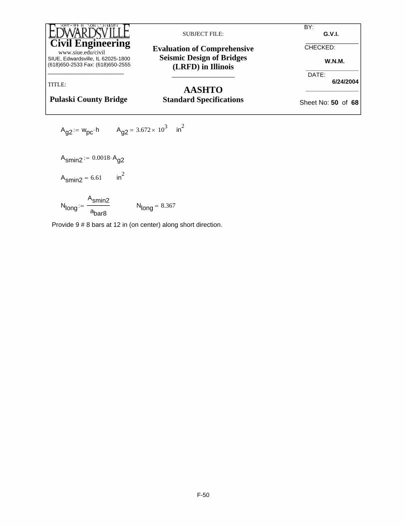
Civil Engineering www.siue.edu/civilSIUE, Edwardsville, IL 62025-1800(618)650-2533 Fax: (618)650-2555_______________________
TITLE:
Pulaski County Bridge
SUBJECT FILE:
Evaluation of Comprehensive Seismic Design of Bridges
(LRFD) in Illinois___________________
AASHTOStandard Specifications
BY: _________ G.V.I.______
________________CHECKED: _____
W.N.M.-------________________DATE:__________
6/24/2004________________
Sheet No: 50 of 68
Ag2 wpc h⋅:= Ag2 3.672 103×= in2
Asmin2 0.0018 Ag2⋅:=
Asmin2 6.61= in2
NlongAsmin2abar8
:= Nlong 8.367=
Provide 9 # 8 bars at 12 in (on center) along short direction.
F-50

Civil Engineering www.siue.edu/civilSIUE, Edwardsville, IL 62025-1800(618)650-2533 Fax: (618)650-2555_______________________
TITLE:
Pulaski County Bridge
SUBJECT FILE:
Evaluation of Comprehensive Seismic Design of Bridges
(LRFD) in Illinois___________________
AASHTOStandard Specifications
BY: _________ G.V.I.______
________________CHECKED: _____
W.N.M.-------________________DATE:__________
6/24/2004________________
Sheet No: 51 of 68
factored MMun
R:=
R 2:=
k ft−Mun 3450.6:=
kV 130.7:=
- for shearΦ 0.85:=
-Hight of beamftl 21:=
-Distance from reinforcement to extreme compression fiberftd 15.675=
assumed( )d 0.95 h⋅:=
-Width of beamftb 2.5:=
-Depth of beamfth 16.5:=
psify 60000:=
psifc 3500:=
Load Combination COMD2
Deep beam design (Reinforced concrete, Nawy, 4rd edition, section 6.9)
Design checks for Pier # 2 (fixed)
F-51

Civil Engineering www.siue.edu/civilSIUE, Edwardsville, IL 62025-1800(618)650-2533 Fax: (618)650-2555_______________________
TITLE:
Pulaski County Bridge
SUBJECT FILE:
Evaluation of Comprehensive Seismic Design of Bridges
(LRFD) in Illinois___________________
AASHTOStandard Specifications
BY: _________ G.V.I.______
________________CHECKED: _____
W.N.M.-------________________DATE:__________
6/24/2004________________
Sheet No: 52 of 68
-Nominal shear resisting force (controls)
Vcmax 6 fc⋅ b⋅ d⋅1441000⋅:=
Vcmax 2.003 103×= k -Maximum nominal shear resisting force
Φ Vc⋅ 567.535= k
Vu 2.27 103×= must be less or equal than Φ Vc Vs+( )⋅
Φ Vc⋅ < Vu -Shear reinforcement is required
Vu Φ Vc⋅− Φ Vs⋅≤
VsVuΦ
Vc−:=
Vs 2.003 103×= k
ld
1.34= < 2.5 - criteria determining Deep Beam
Forld
< 2.0 - use following eq.
Vu Φ 8 fc⋅ b⋅ d⋅( )⋅1441000⋅:=
Vu 2.27 103×= k -Factored shear force
V 130.7= k < Vu 2.27 103×= k OK
Vc 2 fc( )⋅ b⋅ d⋅1441000⋅:=
Vc 667.689= k
F-52

Civil Engineering www.siue.edu/civilSIUE, Edwardsville, IL 62025-1800(618)650-2533 Fax: (618)650-2555_______________________
TITLE:
Pulaski County Bridge
SUBJECT FILE:
Evaluation of Comprehensive Seismic Design of Bridges
(LRFD) in Illinois___________________
AASHTOStandard Specifications
BY: _________ G.V.I.______
________________CHECKED: _____
W.N.M.-------________________DATE:__________
6/24/2004________________
Sheet No: 53 of 68
or 1.5 ft -use this value
sh 1.5:= ft -Distance between horizontal (transverse) rebars (on center)
tr 10.44:= in -Clear spacing between rebars;
tr 1.56+( )12
1= ft
sv 1.0:= ft -Distance between vertical rebars (on center);PCACOL (file:#11BOT2)
Atrsh
⎛⎜⎜⎝
⎞
⎠
1hd
⎛⎜⎝
⎞⎠
+⎡⎢⎣
⎤⎥⎦
12⋅
⎡⎢⎢⎢⎣
⎤⎥⎥⎥⎦
Alsv
⎛⎜⎜⎝
⎞
⎠
11hd
⎛⎜⎝
⎞⎠
−⎡⎢⎣
⎤⎥⎦
12⋅
⎡⎢⎢⎢⎣
⎤⎥⎥⎥⎦
fy⋅ d⋅+ Vs=
K1Atrsh
⎛⎜⎜⎝
⎞
⎠
1hd
⎛⎜⎝
⎞⎠
+⎡⎢⎣
⎤⎥⎦
12⋅:= K1 6.969 10 4−×=
K2Alsv
⎛⎜⎜⎝
⎞
⎠
11hd
⎛⎜⎝
⎞⎠
−⎡⎢⎣
⎤⎥⎦
12⋅:= K2 0.018=
As1 1.56:= in2 Cross sectional area of # 11 rebar
Al As12
144⋅:= Al 0.022= ft2 Area of trans. rebars placed at distance str
Astr 0.44:= in2 Cross sectional area of # 6 rebar
Atr Astr2
144⋅:= Atr 6.111 10 3−×= ft2 Area of long. rebars placed at distance sl
strmaxd5
:= strmax 3.135= ft -Maximum distance between rebarsin transverse direction (on center)
F-53
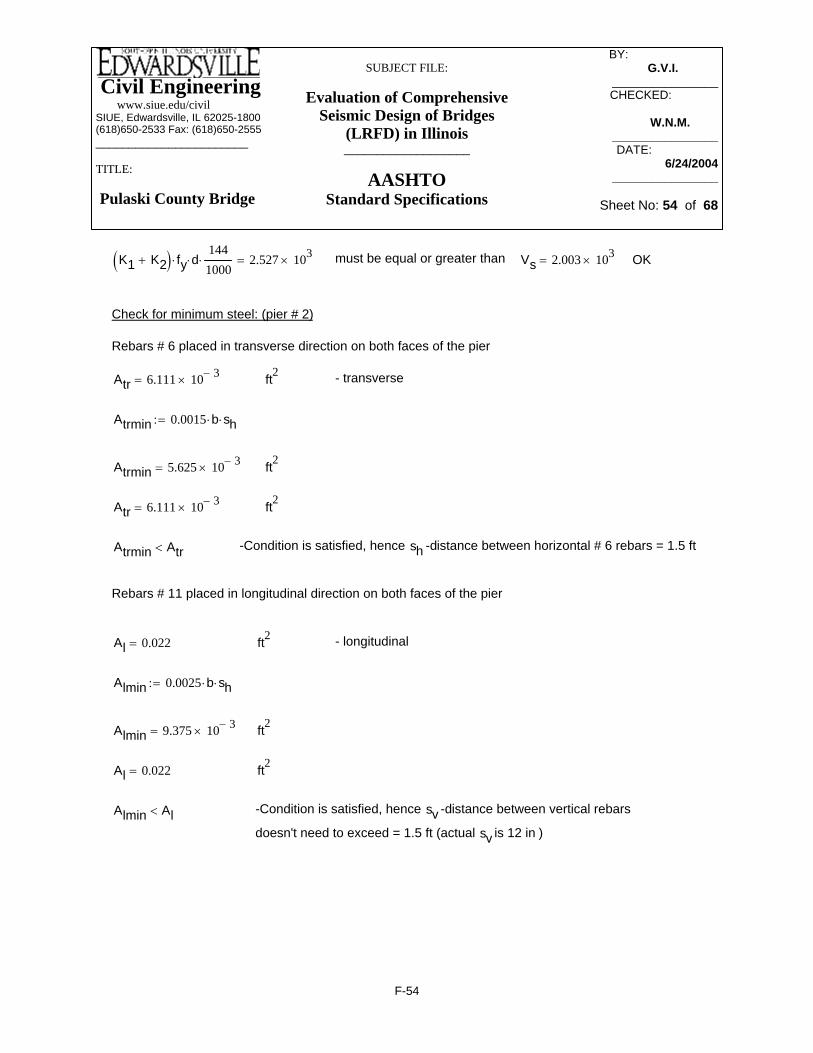
Civil Engineering www.siue.edu/civilSIUE, Edwardsville, IL 62025-1800(618)650-2533 Fax: (618)650-2555_______________________
TITLE:
Pulaski County Bridge
SUBJECT FILE:
Evaluation of Comprehensive Seismic Design of Bridges
(LRFD) in Illinois___________________
AASHTOStandard Specifications
BY: _________ G.V.I.______
________________CHECKED: _____
W.N.M.-------________________DATE:__________
6/24/2004________________
Sheet No: 54 of 68
-Condition is satisfied, hence sv -distance between vertical rebars
doesn't need to exceed = 1.5 ft (actual sv is 12 in )
Almin Al<
ft2Al 0.022=
ft2Almin 9.375 10 3−×=
Almin 0.0025 b⋅ sh⋅:=
- longitudinal ft2Al 0.022=
Rebars # 11 placed in longitudinal direction on both faces of the pier
-Condition is satisfied, hence sh -distance between horizontal # 6 rebars = 1.5 ftAtrmin Atr<
ft2Atr 6.111 10 3−×=
ft2Atrmin 5.625 10 3−×=
Atrmin 0.0015 b⋅ sh⋅:=
- transverse ft2Atr 6.111 10 3−×=
Rebars # 6 placed in transverse direction on both faces of the pier
Check for minimum steel: (pier # 2)
OKVs 2.003 103×=must be equal or greater thanK1 K2+( ) fy⋅ d⋅1441000⋅ 2.527 103×=
F-54

Civil Engineering www.siue.edu/civilSIUE, Edwardsville, IL 62025-1800(618)650-2533 Fax: (618)650-2555_______________________
TITLE:
Pulaski County Bridge
SUBJECT FILE:
Evaluation of Comprehensive Seismic Design of Bridges
(LRFD) in Illinois___________________
AASHTOStandard Specifications
BY: _________ G.V.I.______
________________CHECKED: _____
W.N.M.-------________________DATE:__________
6/24/2004________________
Sheet No: 55 of 68
-number of rebars resisting tension (in transverse dir.) as acquired from PCACOL design (file:#11BOT2)
ntr 8.15=
ntrysv
2⋅ 2+:=
ftsv 1=-Distance between vertical rebars (on center) as acquired from PCACOL design (file:#11BOT2)
fty 3.075=
-Depth over which flex. reinf. is to be distributed (in transverse direction) y 0.25 h⋅ 0.05 l⋅−:=
-controls in2Asmin2 18.81=Asmin2 200 b⋅d 144⋅
fy⋅:=
in2Asmin1 16.692=Asmin1 max 3fc
fy⋅ b⋅ d⋅ 144⋅
⎛⎜⎜⎝
⎞
⎠:=
in2As 2.958=As
M 144⋅
Φ fy⋅ j⋅ d⋅1441000⋅
:=
Minimum reinforcement area
ftj d⋅ 10.8=
j 0.689=
j .2l 2 h⋅+( )
d:=
> 1 so jd=0.2*(l+2h)lh
1.273=
k ft−M 1.725 103×=
Φ 0.9:=
Flexure design for deep beam (pier # 2)
F-55

Civil Engineering www.siue.edu/civilSIUE, Edwardsville, IL 62025-1800(618)650-2533 Fax: (618)650-2555_______________________
TITLE:
Pulaski County Bridge
SUBJECT FILE:
Evaluation of Comprehensive Seismic Design of Bridges
(LRFD) in Illinois___________________
AASHTOStandard Specifications
BY: _________ G.V.I.______
________________CHECKED: _____
W.N.M.-------________________DATE:__________
6/24/2004________________
Sheet No: 56 of 68
As1 1.56:= in2 -cross section area of # 11 rebar
As As1 ntr⋅:= As 12.714= in2 -Total cross section area of rebars available to resist flexure
As 12.714= in^2 must be equal or greater than Asmin2 18.81= in^2 not satisfactory
Number of rebars required for flexure:
NreqAsmin2
As1:=
Nreq 12.058= -number of #11bars to be placed within distance y 3.075= ft from extreme tension fiber
F-56
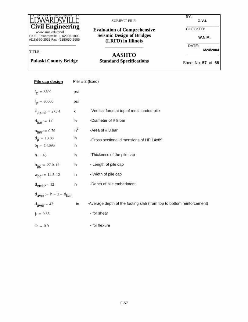
Civil Engineering www.siue.edu/civilSIUE, Edwardsville, IL 62025-1800(618)650-2533 Fax: (618)650-2555_______________________
TITLE:
Pulaski County Bridge
SUBJECT FILE:
Evaluation of Comprehensive Seismic Design of Bridges
(LRFD) in Illinois___________________
AASHTOStandard Specifications
BY: _________ G.V.I.______
________________CHECKED: _____
W.N.M.-------________________DATE:__________
6/24/2004________________
Sheet No: 57 of 68
h 46:= in -Thickness of the pile cap
bpc 27.0 12⋅:= in - Length of pile cap
wpc 14.5 12⋅:= in - Width of pile cap
demb 12:= in -Depth of pile embedment
daver h 3− dbar−:=
daver 42= in -Average depth of the footing slab (from top to bottom reinforcement)
φ 0.85:= - for shear
Φ 0.9:= - for flexure
Pile cap design Pier # 2 (fixed)
fc 3500:= psi
fy 60000:= psi
Paxial 273.4:= k -Vertical force at top of most loaded pile
dbar 1.0:= in -Diameter of # 8 bar
abar 0.79:= in2 -Area of # 8 bar
dp 13.83:= in -Cross sectional dimensions of HP 14x89bf 14.695:= in
F-57

Civil Engineering www.siue.edu/civilSIUE, Edwardsville, IL 62025-1800(618)650-2533 Fax: (618)650-2555_______________________
TITLE:
Pulaski County Bridge
SUBJECT FILE:
Evaluation of Comprehensive Seismic Design of Bridges
(LRFD) in Illinois___________________
AASHTOStandard Specifications
BY: _________ G.V.I.______
________________CHECKED: _____
W.N.M.-------________________DATE:__________
6/24/2004________________
Sheet No: 58 of 68
OK Vuφ
Vc.max<kVuφ
321.647=
(controles) -Maximum nominal shear strengthkVc.max 2.237 103×=
Vc.max 4 fc⋅bo daver⋅
1000⋅:=
-Nominal shear strengthkVc2 3.206 106×=
Vc2 2α daver⋅
bo+
⎛⎜⎜⎝
⎞
⎠fc⋅ bo⋅ daver⋅:=
α 20:=
-Nominal shear strengthkVc1 3.223 106×=
Vc1 24βc
+⎛⎜⎝
⎞
⎠fc⋅ bo⋅ daver⋅:=
βc 1.063=βcbfdp
:=
-Perimeter of critical cross sectioninbo 225.05=
bo dp daver+( ) 2⋅ bf daver+( ) 2⋅+:=
kVu 273.4=
Vu Paxial:=
Pile punching shear check:
F-58

Civil Engineering www.siue.edu/civilSIUE, Edwardsville, IL 62025-1800(618)650-2533 Fax: (618)650-2555_______________________
TITLE:
Pulaski County Bridge
SUBJECT FILE:
Evaluation of Comprehensive Seismic Design of Bridges
(LRFD) in Illinois___________________
AASHTOStandard Specifications
BY: _________ G.V.I.______
________________CHECKED: _____
W.N.M.-------________________DATE:__________
6/24/2004________________
Sheet No: 59 of 68
bo 2 16 2.5+( )⋅ 12⋅ daver+:= in - Perimeter of the failure plane
bo 486= in
Vc 4 fc⋅ bo⋅daver1000
⋅:=
Vc 4.83 103×=
φ Vc⋅ 4.106 103×= k
φ Vc⋅ Vu1> OK
Flexure bending design: (longitudinal direction;short bars)
Mu 5Paxial( ) 1000⋅ 57⋅:=
Mu 7.792 107×= lb in− Φ 0.9:=
One way shear check:
Paxial 273.4= k
Vu 5Paxial:=
Vu 1.367 103×= k
daver 42= inVc1 2 fc⋅ bpc⋅daver1000
⋅:=
φ Vc1⋅ 1.369 103×= k
φ Vc1⋅ Vu> OK
Two way shear check:
Vu1 2 6 Paxial⋅( )⋅:=
Vu1 3.281 103×= k
F-59

Civil Engineering www.siue.edu/civilSIUE, Edwardsville, IL 62025-1800(618)650-2533 Fax: (618)650-2555_______________________
TITLE:
Pulaski County Bridge
SUBJECT FILE:
Evaluation of Comprehensive Seismic Design of Bridges
(LRFD) in Illinois___________________
AASHTOStandard Specifications
BY: _________ G.V.I.______
________________CHECKED: _____
W.N.M.-------________________DATE:__________
6/24/2004________________
Sheet No: 60 of 68
lb in−Mcr 4.227 107×=
Mcrfr Ig⋅
yt:=
in4Ig 2 106×=Igbpc daver
3⋅
12:=
psifr 443.706=fr 7.5 fc⋅:=
inyt 21=ytdaver
2:=
OKΦ Mn⋅ Mu>
lb in−Φ Mn⋅ 2.799 108×=
lb in−Mn 3.11 108×=
Mn As fy⋅ davera2
−⎛⎜⎝
⎞⎠
⋅:=
ina 8.554=
aAs fy⋅( )
0.85 fc⋅ bpc⋅:=
in2As 137.423=
AsMu
Φ fy⋅ a⋅:=
assumed( )a 0.25 daver⋅:=
in2Asmin 45.36=
Asmin200 bpc⋅ daver⋅( )
fy:=
F-60

Civil Engineering www.siue.edu/civilSIUE, Edwardsville, IL 62025-1800(618)650-2533 Fax: (618)650-2555_______________________
TITLE:
Pulaski County Bridge
SUBJECT FILE:
Evaluation of Comprehensive Seismic Design of Bridges
(LRFD) in Illinois___________________
AASHTOStandard Specifications
BY: _________ G.V.I.______
________________CHECKED: _____
W.N.M.-------________________DATE:__________
6/24/2004________________
Sheet No: 61 of 68
ina 8.551=
aAs fy⋅( )
0.85 fc⋅ wpc⋅:=
governs−in2As 73.775=
AsMu
Φ fy⋅ a⋅:=
assumed( )a 0.25 daver⋅:=
in2Asmin 24.36=
Asmin200 wpc⋅ daver⋅( )
fy:=
Φ 0.9:=lb in−Mu 4.183 107×=
Mu 3 Paxial⋅ 1000⋅ 4.25⋅ 12⋅:=
(transverse direction; long bars)Flexure bending design:
Short Bars use: 58 # 8- Number of short barsNL 57.418=
NLAsminabar8
:=
OKΦ Mn⋅ 1.2Mcr>
lb in−1.2Mcr 5.072 107×=
lb in−Φ Mn⋅ 2.799 108×=
F-61

Civil Engineering www.siue.edu/civilSIUE, Edwardsville, IL 62025-1800(618)650-2533 Fax: (618)650-2555_______________________
TITLE:
Pulaski County Bridge
SUBJECT FILE:
Evaluation of Comprehensive Seismic Design of Bridges
(LRFD) in Illinois___________________
AASHTOStandard Specifications
BY: _________ G.V.I.______
________________CHECKED: _____
W.N.M.-------________________DATE:__________
6/24/2004________________
Sheet No: 62 of 68
Long Bars use: 30 # 6- Number of short barsNL 30.835=
NLAsminabar8
:=
OKΦ Mn⋅ 1.2Mcr>
lb in−1.2Mcr 5.072 107×=
lb in−Φ Mn⋅ 8.148 107×=
lb in−Mcr 4.227 107×=
Mcrfr Ig⋅
yt:=
in4Ig 2 106×=Igbpc daver
3⋅
12:=
psifr 443.706=fr 7.5 fc⋅:=
inyt 21=ytdaver
2:=
OKΦ Mn⋅ Mu>
lb in−Φ Mn⋅ 8.148 107×=
lb in−Mn 9.054 107×=
Mn 40 fy⋅ davera2
−⎛⎜⎝
⎞⎠
⋅:=
F-62

Civil Engineering www.siue.edu/civilSIUE, Edwardsville, IL 62025-1800(618)650-2533 Fax: (618)650-2555_______________________
TITLE:
Pulaski County Bridge
SUBJECT FILE:
Evaluation of Comprehensive Seismic Design of Bridges
(LRFD) in Illinois___________________
AASHTOStandard Specifications
BY: _________ G.V.I.______
________________CHECKED: _____
W.N.M.-------________________DATE:__________
6/24/2004________________
Sheet No: 63 of 68
inwpc 174=- Width of pile capinwpc 14.5 12⋅:=
inbpc 324=- Length of pile capinbpc 27.0 12⋅:=
-Thickness of the pile capinh 46:=
- for flexureΦ 0.9:=
-Average depth of the footing slab (from top to bottom reinforcement)indaver 42=
psifc 3.5 103×=
- Moment armftMarm 4.75:=
- Number of pilesn 5:=
- Uplift force on a single pile (Fixed pier ; load combination COMD1)kFuplift 144.0:=
Top reinforcement
F-63

Civil Engineering www.siue.edu/civilSIUE, Edwardsville, IL 62025-1800(618)650-2533 Fax: (618)650-2555_______________________
TITLE:
Pulaski County Bridge
SUBJECT FILE:
Evaluation of Comprehensive Seismic Design of Bridges
(LRFD) in Illinois___________________
AASHTOStandard Specifications
BY: _________ G.V.I.______
________________CHECKED: _____
W.N.M.-------________________DATE:__________
6/24/2004________________
Sheet No: 64 of 68
Provide 34 # 8 bars at 9.75 in (on center) along short direction.
Nshort 33.958=NshortAsmin1abar8
:=
in2Asmin1 26.827=Asmin1 0.0018 Ag1⋅:=
in2Ag1 1.49 104×=Ag1 bpc h⋅:=
- provide minimum reinforcement (shrinkage reinforcement)Φ Mnom⋅ 1.2 Mcr⋅<
lb in−1.2 Mcr⋅ 4.631 107×=
lb in−Φ Mnom⋅ 4.104 107×=
MnomMultΦ
:=
lb in−Mcr 3.859 107×=Mcrfr Ig( )⋅
yt:=
inyt 23=yth2
:=
in4Ig 2 106×=
Igbpc daver( )3⎡
⎣⎤⎦⋅
12:=
psifr 443.706=
fr 7.5 fc⋅:=
lb in−Mult 4.104 107×=
Mult n Fuplift⋅ Marm⋅ 1000⋅ 12⋅:=
F-64

Civil Engineering www.siue.edu/civilSIUE, Edwardsville, IL 62025-1800(618)650-2533 Fax: (618)650-2555_______________________
TITLE:
Pulaski County Bridge
SUBJECT FILE:
Evaluation of Comprehensive Seismic Design of Bridges
(LRFD) in Illinois___________________
AASHTOStandard Specifications
BY: _________ G.V.I.______
________________CHECKED: _____
W.N.M.-------________________DATE:__________
6/24/2004________________
Sheet No: 65 of 68
Ag2 wpc h⋅:= Ag2 8.004 103×= in2
Asmin2 0.0018 Ag2⋅:=
Asmin2 14.407= in2
NlongAsmin2abar8
:= Nlong 18.237=
Provide 19 # 8 bars at 9.5 in (on center) along short direction.
F-65

Civil Engineering www.siue.edu/civilSIUE, Edwardsville, IL 62025-1800(618)650-2533 Fax: (618)650-2555_______________________
TITLE:
Pulaski County Bridge
SUBJECT FILE:
Evaluation of Comprehensive Seismic Design of Bridges
(LRFD) in Illinois___________________
AASHTOStandard Specifications
BY: _________ G.V.I.______
________________CHECKED: _____
W.N.M.-------________________DATE:__________
6/24/2004________________
Sheet No: 66 of 68
PCACOL Output
Piers # 1 & # 3 (fixed). At base for load combination COMB1
Piers # 1 & # 3 (fixed). At base for load combination COMB2
F-66

Civil Engineering www.siue.edu/civilSIUE, Edwardsville, IL 62025-1800(618)650-2533 Fax: (618)650-2555_______________________
TITLE:
Pulaski County Bridge
SUBJECT FILE:
Evaluation of Comprehensive Seismic Design of Bridges
(LRFD) in Illinois___________________
AASHTOStandard Specifications
BY: _________ G.V.I.______
________________CHECKED: _____
W.N.M.-------________________DATE:__________
6/24/2004________________
Sheet No: 67 of 68
Pier # 2 (fixed). At base for load combination COMB1
Pier # 2 (fixed). At base for load combination COMB2
F-67

Civil Engineering www.siue.edu/civilSIUE, Edwardsville, IL 62025-1800(618)650-2533 Fax: (618)650-2555_______________________
TITLE:
Pulaski County Bridge
SUBJECT FILE:
Evaluation of Comprehensive Seismic Design of Bridges
(LRFD) in Illinois___________________
AASHTOStandard Specifications
BY: _________ G.V.I.______
________________CHECKED: _____
W.N.M.-------________________DATE:__________
6/24/2004________________
Sheet No: 68 of 68
Minimum seat width
For Seismic Performance Category C
L 236.5:= ft - Length of bridge
H 23:= ft - Height of the tallest pier
S 0:= - Angle of skew
N 12 0.03 L⋅+ 0.12 H⋅+( ) 1 0.000125 S2⋅+( )⋅:=
N 21.855= in - Minimum width of support
F-68

APPENDIX G - SOIL PROFILES AT ILLINOIS BRIDGE SITES
G-1

Johnson County Bridge Soil Profile
400
390
19 33
9
25 10
18
22 25
100/1"
1421
15 24
100/3"
100/6"
15 80
2822
24
20
100/5"
15
1212
11 96
26
21
5
15
325
23
31
9
6
100/6"
12
1524
2924
27
24
37
11 10010014
9
20 3016
100/3" 100/5"
22 26
2118
23
400
390
40 60 80 100
380
370
360
350
380
26 633
0 20
28 13
2
92%82%
370
360
26 12
350
38
25
Medium stiff, moist silty CLAY to soft CLAY (1)
Medium stiff to stiff, moist to very moist silty CLAY to stiff to very stiff CLAY (2)
Stiff to hard, clay SHALE (3)
Hard LIMESTONE with occasional shale seams (5)
Boring 55 (N. Abut.)Sta. 408+06Elev. 379.4 ft.
Boring 65 (N. Pier)Sta. 408+39Elev. 379.0 ft.
Boring 75 (S. Pier)Sta. 408+85Elev. 381.4 ft.
Boring 85 (N. Pier) Sta. 409+19Elev. 381.7 ft.
Medium stiff, moist silty CLAY to soft CLAY (1)
Medium stiff,moist silty
CLAY to softCLAY (1)
Fill added after Soil Exploration
Fill added after Soil Exploration
?
Approx. Elev. at bottom of Abut. Cap
Approx. Elev. atbottom of Abut. Cap
Stiff to HardSANDSTONE
with clay binderMedium stiff to stiff, moist to very moist silty CLAY to stiff to very stiff CLAY (2)
Medium stiff to stiff,moist to very moist
silty CLAY to stiff tovery stiff CLAY (2)
Stiff to hard, clay SHALE (3)
Stiff to hard, clay SHALE (3)
?
Stiff to Hard SANDSTONE with clay binder (4)
Split Spoon REFUSAL
Split Spoon REFUSAL
G-2

St. Clair County Bridge Soil Profile
G-3

Pulaski County Bridge Soil Profile
2028
26232024222019
945
28
9637
45
1717263528
512
30
9643
33
3172534
30
26
69
282826
34
70666869
32
2328261713
6558
9
67
22
14
66
59
65
61
65
60
30 60 90 120 150 180 210 2400
611
420
192925217
7
1642
8
47 38
23
40
33
380
4474
69696868
24
370360
24
28
22
24
14
19
28
15
410400
390450
440430
67
410
390
400
380
450
440
430
420
52
360
370
38
33
32
65 30
36
25
29 23
36 21
21
21
24
24
15
23
19
22
64100
26101418
68576739
7499
3810
61004129
3629292937263331
6131114
984232
302517
23
27 5
23 8
272011
47
22
Soft to stiff, damp to moist silty CLAY to
CLAY to SILT
Medium to very dense, wet to moist coarse SAND & GRAVEL
Stiff, moist silty CLAY to medium to hard, moist to
damp CLAY
Stiff to very stiff, dampto moist sandy (some clay seams) CLAY to
CLAY
Medium to fine, dense, wet SAND
Medium, wet sandy CLAY
* FILL
Medium to very dense, wet to moist coarse SAND & GRAVEL
Soft to stiff, damp to moist silty CLAY to CLAY to SILT
Stiff, moist silty CLAY to medium to hard, moist
to damp CLAY
Stiff, moist silty CLAY to medium to hard, moist to
damp CLAY
Stiff, moist silty CLAY to medium to hard, moist to
damp CLAY
Soft to stiff, damp to moist silty CLAY to
CLAY to SILT
Soft to stiff, damp to moist silty CLAY to CLAY to SILT
Stiff to very stiff, damp to moist sandy (some clay seams) CLAY to CLAY
Medium to very dense, wet to moist
coarse SAND & GRAVEL
Medium to very dense, wet to moist coarse SAND & GRAVEL
Boring 1: W. Abut. Elev. 424.9 ft. (Sta. 8 + 82)GWT (after 72 hrs.): 420.9 ft.
Boring 2 : Pier #1 Elev. 426.6 ft. (Sta. 9 + 25)GWT (after 24 hrs.): 423.6 ft.
Boring 3 : Pier #2 Elev. 426.6 ft. (Sta. 10B + 00)GWT (after 24 hrs.): 422.1 ft.
* FILL
Boring 4 : Pier #3 (Sta. 10B + 75)Elev. 431.2 ft.
GWT (after 24 hrs.): 422.2 ft.
* FILL
Boring 5 : E. AbutElev. 431.8 ft. (Sta. 11B + 18)GWT (after 72 hrs.): 427.8 ft.
* FILL
*FILL added after soil completion of soil exploration
?
?
?
G-4

Madison-Pulaski County Bridge Soil Profile
Elev. (ft)
57
17
18
26
21
29
42
47
385
2
2
27
31
33
405
400
395
390
Elev. (ft)420
415
410
320
315
310
305
340
335
330
325
350
345
380
375
370
365
370
365
420
415
410
405
400
395
390
385
305
340
335
330
325
320
315
310
360
355
350
345
380
375
295
41
57
48
32
33
30
25
0
52
43
34
36
300
70
360
355
10
11
23
398 133
34
835334
3
20
33374143
2
1
60/0.5"
31
24
100/0.3"
18
35
2
0
16
16
14
17
32
23
23
17
44
37
23
25
23
11
4
6
2
10
4
4
4 31
0
1216
17
20
57
28
8
25
55
20
60
44
20
24
34
37
31
31
43
2
2
2
2
0
15
16
29
29
32
20
24
37
32
32
44
47
66
35
25
44
Medium Dense to Dense Gray, Fine to
Coarse Sand
?
?End of Boring End of Boring
??
Soft to med. Stiff Gray, Silty Loam with layers of silty
Clay
Soft Gray Limestone W/Shale Streaks
? End of Boring
?
??
Medium Dense to Dense Gray, Fine to
Coarse Sand
Medium Dense to Dense Gray, Fine to
Coarse Sand
Soft to med. Stiff Gray, Silty Loam with layers of silty
Clay
Soft to med. Stiff Gray, Silty Loam with layers of silty
Clay
Loose Sand
Loose Sand
Very Soft Very Soft
Boring 1: S. Abut. Elev. 418.4 ft. (Sta. 117+22)
Boring 2: S. Pier Elev. 408.1 ft. (Sta. 118+75)
Boring 3: N. Abut. Elev. 417 ft. (Sta. 120+66) Boring 4: N. Pier
Elev. 412.5 ft. (Sta. 120+79)
G-5