Evaluation of Cleaning and Rehabilitation of … of Cleaning and Rehabilitation of University of...
42
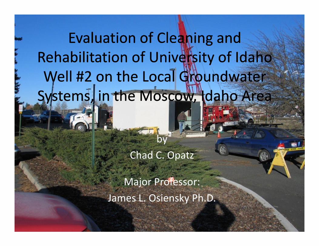
Evaluation of Cleaning and Evaluation of Cleaning and Rehabilitation of University of Idaho Well #2 on the Local Groundwater Rehabilitation of University of Idaho Well #2 on the Local Groundwater Well #2 on the Local Groundwater Systems, in the Moscow, Idaho Area Well #2 on the Local Groundwater Systems, in the Moscow, Idaho Area by by Chad C. Opatz Major Professor: James L. Osiensky Ph.D. James L. Osiensky Ph.D.
Transcript of Evaluation of Cleaning and Rehabilitation of … of Cleaning and Rehabilitation of University of...
Evaluation of Cleaning and Evaluation of Cleaning and gRehabilitation of University of Idaho Well #2 on the Local Groundwater
gRehabilitation of University of Idaho Well #2 on the Local GroundwaterWell #2 on the Local Groundwater Systems, in the Moscow, Idaho AreaWell #2 on the Local Groundwater Systems, in the Moscow, Idaho Area
byby
Chad C. Opatz
Major Professor:
James L. Osiensky Ph.D.James L. Osiensky Ph.D.

AcknowledgementsAcknowledgements
PBAC
Jim Osiensky
Tim Link
Gary JohnsonJim Osiensky
Jerry Fairley
J h B h
Gary Johnson
IDWR
John Bush
Hannah Hernandez, Mark Nell, Aaren Fiedler, John Livingston

ID
WA
ORID
History of Well UI#2History of Well UI#2
Construction started in 1950
Completed in 1958Completed in 1958
Sand invasion problems
Production terminated 1964Production terminated 1964
Attempt to place back on line in early 80’s

History of Well UI#2History of Well UI#2
University of Idaho road extension
Proposed well UI#2 abandonmentProposed well UI#2 abandonment
2004 borehole video on well UI#2

Well UI#2 Borehole Conditions ‘04Well UI#2 Borehole Conditions 04

Proposal of Well UI#2 ProjectProposal of Well UI#2 Project
UI#2 conditions were proposed to PBAC as aUI#2 conditions were proposed to PBAC as a feasibility study.
Attempt to increase flow downward in UI#2 borehole pby cleaning and rehabilitation.
PBAC granted the funding for UI#2 Project starting g g j g2005

PurposePurpose
Investigate borehole water movement within the University of Idaho Well #2 to provide a background for comparison to hydraulic effects resulting from the cleaning of the well.

General ObjectiveGeneral Objective
Delineate the effects of well cleaning and well development on the groundwater flow systems indevelopment on the groundwater flow systems in the vicinity of well UI#2.

Specific ObjectivesSpecific Objectives
Describe the geologic and hydrogeologic controls on groundwater movement in the Moscow Idaho areagroundwater movement in the Moscow, Idaho area.
D l t l h d l i d lDevelop a conceptual hydrogeologic model.
l h ff f l h l lDelineate the effects of UI#2 cleaning on the local groundwater flow environment.

Palouse Basin GeologyPalouse Basin Geology

Local GeologyLocal Geology

UI#2 Site GeologyUI#2 Site Geology

Conceptual Hydrologic Model Before Cleaning
C’C

Monitoring ProgramMonitoring Program
Monitor ground water levels and ground waterMonitor ground water levels and ground water temperatures in the following:
• Paradise Creek
• Sediments of Bovill
• Lolo basaltLolo basalt
• Vantage sediments

Monitoring Program

UI#2 Site Geology (Paradise Creek)UI#2 Site Geology (Paradise Creek)N1 N2 N3 fbls

Monitoring Program
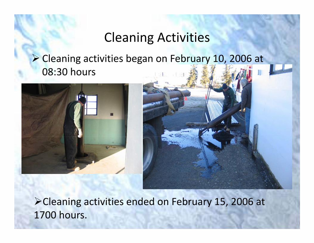
Cleaning ActivitiesCleaning activities began on February 10, 2006 at 08:30 hours
Cl i i i i d d F b 15 2006Cleaning activities ended on February 15, 2006 at 1700 hours.

Cleaning Activities
Conditions in well UI#2 borehole after cleaningcleaning.

Problem!Problem!
When did UI#2 start to effect the local groundwaterWhen did UI#2 start to effect the local groundwater flow environment (i.e., injection)?
Total cleaning process was completed over 129 hours g p pspread over the daylight working hours of three days.
Physical EvidencePhysical Evidence
In the morning of February 14, 2006 pieces of steelIn the morning of February 14, 2006 pieces of steel well casing were bailed from the bottom of UI#2.
This evidence was considered to be when a change in gflow occurred in well UI#2 borehole.

Conceptual Hydrologic Model as a Result of Cleaning

Analysis
Water level data collected in well UI#2
Analysis
Water level data collected in well UI#2
Data collected in sediments of Bovill and Paradise Creek (T6) adjacent to UI#2( ) j
Data collected in local monitoring wells and USGS gauging station.g g g

UI#2 Water Level Data AnalysisUI#2 Water Level Data Analysis
Date of hand measurement of wl in UI#2 Water level elevation
02/01/2006 2502.65 famsl*
02/10/2006 note: after bailing ended 2497.48 famsl
02/14/2006 note: after pumping for 2507 famsl50min at 40 gpm
2/22/2006 2502.65 famsl*
03/03/2006 2502 famsl/ /
D iDarcy equation:Q = KIA
where:Q = discharge rate (l^3/t)K = hydraulic conductivity (l/t)I = hydraulic gradient (l/l)I = hydraulic gradient (l/l)A = cross sectional area (l^2)

Analysis of Paradise Creek and Sediments of Bovill Water Level

Analysis of Paradise Creek and Sediments of Bovill Water Level

Analysis of Paradise Creek and Sediments of Bovill Temperatures
Analysis of Water Levels in Local Monitoring W ll
Water level rise in local monitoring wells appeared to
Wells
g ppcoincide with cleaning activities.
The water level data from local monitoring wells were analyzed in AQTESOLV to show theoretically weather or not cleaning activities were the cause.

Analysis of Water Levels in Local Monitoring W ll
Theis Equation (1935) for a confined aquifer system
Wells
Theis Equation (1935) for a confined aquifer system where:s = Drawdown [L]Q = Pumping rate [L^3/T]Q Pumping rate [L 3/T]T = Transmissivity [L^2/T]t = timeS = Storativity [dimensionless]r = Radial distance from
P mping ell [L]
Additi l ti
Pumping well [L]W(u) = The well function of u
Additional assumptions: 1) Injection can be treated as pumping in AQTESOLV by changing the sign of
the water level displacements. 2) D i ti f th Th i (1935) ti d t i ifi tl2) Deviations from the Theis (1935) assumptions do not significantly
affect the analysis.

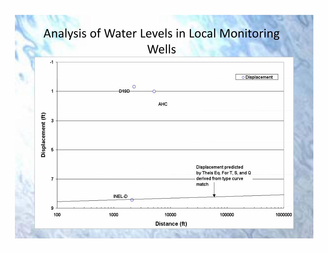
Analysis of Water Levels in Local Monitoring W ll
INEL‐D
Wells

Analysis of Water Levels in Local Monitoring W ll
AQTESOLV parameters:
Wells
Two hour lag time
Aquifer thickness (b) 225 ft
AQTESOLV parameters:
Aquifer thickness (b) 225 ft
Fully penetrating well
Di ( ) f UI#2 INEL 2000 fDistance (r) from UI#2 to INEL = 2000 ft
Injection rate was estimated by trial‐and‐error for a range of Transmissi it and Storati it al esrange of Transmissivity and Storativity values.

Analysis of Water Levels in Local Monitoring W llWells
Type curve match to INEL‐D displacement data

Analysis of Water Levels in Local Monitoring W llWells
D19D

Analysis of Water Levels in Local Monitoring W llWells
AHC well
Analysis of Water Levels in Local Monitoring W llWells

Analysis of Water Levels in Local Monitoring W llWells

Analysis of Water Levels in Local Monitoring W llWells

Analysis of Water Temperature in Local M it i W llMonitoring Wells

ConclusionsConclusions
No permanent change in the borehole flowNo permanent change in the borehole flow environment in well UI#2.
Water levels in the sediments of Bovill wereWater levels in the sediments of Bovill were not affected by cleaning.
W l l i i l l i i llWater level rise in local monitoring wells were a result of a recharge event from Paradise C kCreek.

RecommendationsRecommendations
Conduct visual dye tracer tests in well UI#2Conduct visual dye tracer tests in well UI#2.
Stress well UI#2 under pumping conditions to verify hydraulic connection between Lolo andverify hydraulic connection between Lolo and sediments of Bovill.
E bli h i l i i kEstablish a continual monitoring network at the UIGFL into order to characterize the
h di i (i fl )recharge conditions (i.e., flux).

Thank you.
Questions?