Evaluation of CFD Codes for Hypersonic Flow Modelingmajdalani.eng.auburn.edu/publications/pdf/2010 -...
12
1 American Institute of Aeronautics and Astronautics Evaluation of CFD Codes for Hypersonic Flow Modeling Brian A. Maicke * and Joseph Majdalani † University of Tennessee Space Institute, Tullahoma, TN 37388 The intent of this study is to evaluate existing gaps in computational fluid dynamics (CFD) technology with an emphasis on hypersonic flow modeling. The importance of validation is highlighted, especially with respect to the dearth of available hypersonic flow data. Modeling challenges relevant to hypersonic air-breathing propulsion, such as multi-phase flow and turbulent mixing, are discussed and areas for continued research are identified. Two specialized codes (DPLR and VULCAN) and two general purpose solvers (CFD++ and FLUENT) are also reviewed for use in hypersonic applications. I. Introduction N order to properly address the challenges facing the next generation of computational fluid dynamics (CFD) tools, it is beneficial to review the current state of CFD with respect to the design and evaluation of hypersonic vehicle systems. Given the present climate and pressure to reduce costs and design time, CFD research is underway to not only supplement, but perhaps supplant some wind tunnel and flight tests. While this effort remains a desirable long term objective, the current state of CFD maturity does not allow for its direct substitution for testing, especially when applied to hypersonic flight regimes. A. Barriers to Preliminary Design With the wide array of CFD tools currently available, evaluating CFD codes can be problematic for a non-specialist. Many commercial CFD codes can provide reasonable results for general problems, but for the hypersonic flow regime, codes are often optimized for specific tasks. For a thorough evaluation of a CFD code, one needs to be well versed in both hypersonic flow physics and computational methods. In practice, however, knowledge of these fields can be mutually exclusive. During the preliminary design phase, the two driving parameters in selecting a CFD code are speed and ease of use. Changes in design are common during this phase and any evaluation tool must be capable of quickly providing rough estimates of performance for comparison purposes. Coupled with ease of use is the increased accessibility to CFD codes at the college level. Through such an education, future designers will better understand the limitations of individual modules and gain greater confidence in their results. The net effect of the educational imperative is a well informed engineer that has the proper background to properly use the next generation CFD tools. This becomes exceptionally important when considering hypersonic flow modeling, where CFD simulations employ algorithms targeted for high efficiency in analyzing high speed * Graduate Research Assistant, Mechanical, Aerospace and Biomedical Engineering Department. Member AIAA. † H. H. Arnold Chair of Excellence in Advanced Propulsion , Mechanical, Aerospace and Biomedical Engineering Department . Senior Member AIAA. Fellow ASME. I 46th AIAA/ASME/SAE/ASEE Joint Propulsion Conference & Exhibit 25 - 28 July 2010, Nashville, TN AIAA 2010-7184 Copyright © 2010 by the American Institute of Aeronautics and Astronautics, Inc. All rights reserved.
-
Upload
hoangkhuong -
Category
Documents
-
view
216 -
download
2
Transcript of Evaluation of CFD Codes for Hypersonic Flow Modelingmajdalani.eng.auburn.edu/publications/pdf/2010 -...
1 American Institute of Aeronautics and Astronautics
Evaluation of CFD Codes for Hypersonic Flow Modeling
Brian A. Maicke* and Joseph Majdalani†
University of Tennessee Space Institute, Tullahoma, TN 37388
The intent of this study is to evaluate existing gaps in computational fluid dynamics (CFD) technology with an emphasis on hypersonic flow modeling. The importance of validation is highlighted, especially with respect to the dearth of available hypersonic flow data. Modeling challenges relevant to hypersonic air-breathing propulsion, such as multi-phase flow and turbulent mixing, are discussed and areas for continued research are identified. Two specialized codes (DPLR and VULCAN) and two general purpose solvers (CFD++ and FLUENT) are also reviewed for use in hypersonic applications.
I. Introduction N order to properly address the challenges facing the next generation of computational fluid dynamics (CFD) tools, it is beneficial to review the current state of CFD with respect to the
design and evaluation of hypersonic vehicle systems. Given the present climate and pressure to reduce costs and design time, CFD research is underway to not only supplement, but perhaps supplant some wind tunnel and flight tests. While this effort remains a desirable long term objective, the current state of CFD maturity does not allow for its direct substitution for testing, especially when applied to hypersonic flight regimes.
A. Barriers to Preliminary Design With the wide array of CFD tools currently available, evaluating CFD codes can be problematic for a non-specialist. Many commercial CFD codes can provide reasonable results for general problems, but for the hypersonic flow regime, codes are often optimized for specific tasks. For a thorough evaluation of a CFD code, one needs to be well versed in both hypersonic flow physics and computational methods. In practice, however, knowledge of these fields can be mutually exclusive. During the preliminary design phase, the two driving parameters in selecting a CFD code are speed and ease of use. Changes in design are common during this phase and any evaluation tool must be capable of quickly providing rough estimates of performance for comparison purposes. Coupled with ease of use is the increased accessibility to CFD codes at the college level. Through such an education, future designers will better understand the limitations of individual modules and gain greater confidence in their results. The net effect of the educational imperative is a well informed engineer that has the proper background to properly use the next generation CFD tools. This becomes exceptionally important when considering hypersonic flow modeling, where CFD simulations employ algorithms targeted for high efficiency in analyzing high speed
*Graduate Research Assistant, Mechanical, Aerospace and Biomedical Engineering Department. Member AIAA. †H. H. Arnold Chair of Excellence in Advanced Propulsion, Mechanical, Aerospace and Biomedical Engineering Department. Senior Member AIAA. Fellow ASME.
I
46th AIAA/ASME/SAE/ASEE Joint Propulsion Conference & Exhibit25 - 28 July 2010, Nashville, TN
AIAA 2010-7184
Copyright © 2010 by the American Institute of Aeronautics and Astronautics, Inc. All rights reserved.

2 American Institute of Aeronautics and Astronautics
flows. With the current trends driving down design time, educating designers in CFD must start at the university level. Reduced design times also require CFD code turnaround to be much shorter than previously tolerated. Progress in computer technology that is manifested in increased processor speeds, multi-core technologies, inexpensive memory, and increasingly more efficient programming languages can help to reduce CFD run time for codes, even in the absence of algorithm modification. While advances in this area are beyond the scope of this study, it may be helpful to recall that even five years ago, our available computing power was a fraction of what it is today and that capitalizing on these advances will help to increase the viability of CFD as a design tool. Another opportunity for improvement lies in seeking enhancements to the CFD codes themselves. The increased availability of multi-processor machines empowers the students developing the next generation CFD packages to find more efficient parallel processing algorithms. As these technologies mature, more work will be focused on taking advantage of parallel computing through processes such as functional decomposition. While it is true that many codes already take advantage of parallel processing, there is still potential for substantial strides in this area. For example, the Data Parallel Line Relaxation (DPLR) technique is a relatively new method that facilitates parallel processing for high speed flows.1-4 DPLR is not as widely used as many commercial alternatives, but its quickly expanding user base provides a model for new parallel processing techniques to follow. As more programmers are exposed to these techniques, improvements and alternate methodologies will naturally emerge to further increase efficiency.
B. Validation of Hypersonic Systems A primary concern facing the entire CFD community is the availability of validation data. At the outset, any CFD code that is to be employed should be validated over a generous range of operating parameters for a given design requirement. This is necessary to ensure that the code is capable of representing the necessary physical phenomena; it is also to safeguard against possible numerical, algorithmic or coding errors. The lack of data for comparison is more problematic at hypersonic speeds, where wind tunnel and flight data are scarce. To properly validate a CFD code, it is important that the relevant physical processes and critical parameters be identified to ensure that the code can accurately predict the outcome of a change in parameters. Some of these parameters can be obtained through various scaling laws or asymptotic methods, with the latter being severely overlooked. The use of asymptotic methods to guide computational developments can be greatly beneficial not only in furnishing limiting process comparisons, but also in unraveling the primary control parameters that drive a particular system. It is imperative that the experimental data be properly characterized by these parameters, to the extent that subsequent validations can be benchmarked against legitimate experimental results. During validation, it is vital that the code matches the benchmark experiments as closely as possible; otherwise, validation efforts can be compromised. For example, Ebrahimi5 describes the validation of a parabolized Navier-Stokes solver (PNS) for a supersonic shear layer with tangential injection. To conduct his validation, Ebrahimi compares his results to the experimental data of Burrows and Kurkov6 and finds reasonable agreement with experiments. Two other research teams7,8 were not satisfied with the agreement during the validation process. Ebrahimi attributes this difference to his use of the experimentally measured inlet properties, in contrast to the other researchers who assumed one dimensional properties at the inlet.

3 American Institute of Aeronautics and Astronautics
The validation process requires thorough documentation and disclosure to be of full value to the hypersonic community. First, documentation allows end users to realize the precise range of validity for potential CFD applications. It provides a new user an opportunity to investigate a given configuration through a trial run of a possibly unfamiliar CFD code. Validation can also highlight sensitivity to parameters and initial conditions as was shown in the previous example. Finally, results can be disseminated to the extent of mitigating duplication efforts. Dissemination and sharing will clearly reduce costs associated with this aspect of CFD testing. While there has been interest in hypersonic research since the fifties, the funding for research and development has been cyclical. There has not been a continuous effort to maintain and advance our fundamental knowledge of hypersonic systems. Accordingly, there is a dearth of high fidelity, rigorously documented test data. The National Project for Applications-oriented Research in CFD (NPARC) has taken a bold step in making validation cases freely available on the internet.9 The NPARC archive is a general CFD validation database containing some hypersonic validation cases. Regretfully, no new cases have been added since 2003, thus reducing its value as a comprehensive validation source. Calspan University at Buffalo Research Center has the beginnings of a hypersonic database derived from wind tunnel experiments carried out at their facilities.10 Other online verification resources exist, but a consolidated national database with verified, reliable data would be invaluable for CFD code development. Such a resource would foster communication, reduce duplication of efforts and, most importantly, reduce the cost of the validation process for all users.
C. Challenges in Hypersonic Flow Modeling Modeling of hypersonic engines requires a thorough understanding of some key physical processes. A brief survey of the challenges in modeling these phenomena follows.
1. Multiphase Flow Tracking multiphase flows is of critical importance to CFD-based engine design. In propulsion applications, liquid fuel atomizes during the injection process to provide a spray of fuel that mixes with incoming air and pre-existing combustion products. The atomization process occurs at a significantly smaller scale than the other driving features of the flowfield. Because of the resulting small spatial scale, CFD codes are required to use a droplet model separate from the bulk fluid dynamic solution. Often, simplifying approximations are made for larger scale simulations (see Figure 1). The atomization process is a topic of research in its own right, and work is currently underway to develop CFD codes that could feasibly produce reliable results at such a small scale.11-13
Figure 1. Modeling multiphase flows with adaptive grids, from Uzgoren et al.11
4 American Institute of Aeronautics and Astronautics
2. Combustion Modeling For scramjet applications, accurate combustion modeling drives the design of the engine. In reality, the combustion process is a multitude of forward and backward chemical reactions occurring at different temporal and spatial scales. In liquid and gaseous applications, the problems connected with atomization also directly impact the combustion process. Modeling every combustion reaction in a hypersonic engine is simply too costly in terms of both time and resources, as live fire testing may be required to experimentally account for chemical species. The result is a large body of research dedicated to discovering the principle reactions for fuel and oxidizer combinations that accurately capture the combustion process while requiring less computational overhead than a full accounting of species.
3. Instability Any time large amounts of energy are released in a confined space, the potential for acoustic instability becomes a concern. The prediction of instability in any sort of engine remains one of the leading obstacles for designers. Instabilities exposed in the testing stages are decidedly more costly than those discovered before hardware decisions and qualifications are finalized. Traditionally, codes that address instability do so with empirical correlations. The reliability of these correlations deteriorates when extended to new designs and different operating conditions. Recently, there have been breakthroughs14-16 in the nonlinear modeling of instability, which could be extended and implemented into next generation CFD codes.
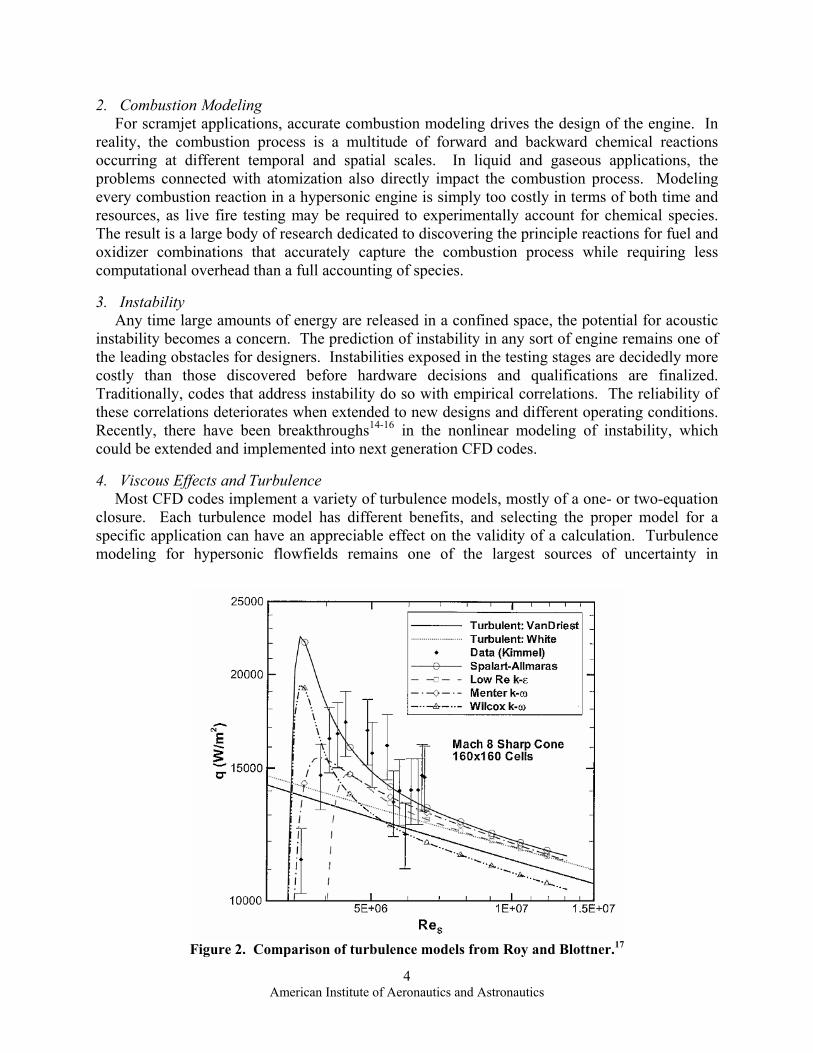
4. Viscous Effects and Turbulence Most CFD codes implement a variety of turbulence models, mostly of a one- or two-equation closure. Each turbulence model has different benefits, and selecting the proper model for a specific application can have an appreciable effect on the validity of a calculation. Turbulence modeling for hypersonic flowfields remains one of the largest sources of uncertainty in
Figure 2. Comparison of turbulence models from Roy and Blottner.17

5 American Institute of Aeronautics and Astronautics
aerodynamic and heating calculations. The paper by Roy and Blottner18 illustrates how vast the discipline of hypersonic turbulence modeling really is. A multitude of implementations are reviewed and compared to both experimental data and other CFD models (see Figure 2). While serving as an excellent review of the current material available, this paper emphasizes that additional hypersonic experiments are required to ensure that high fidelity turbulence models can be developed and verified. Refinement of existing models is also suggested, with compressibility corrections at the vanguard. The large selection of possible turbulence models speaks to the need for a more extensive set of validation data for comparison. Improvements in correlating turbulence models to applications are hoped to permit the next generation CFD programmers to select a suitable turbulence model based on specific applications, thus allowing non-specialists to intelligently apply proper turbulence effects without being a CFD or turbulence modeling expert. Because hypersonic engines are integrated with the air frame, boundary layer transition models are also of key importance in CFD applications. For most traditional combustor/engine combinations, boundary layer transition is more influential in determining vehicle performance and aerodynamics. Since the hypersonic inlet is integrated into the airframe, accurate prediction of boundary layer transitions in the inlet of a hypersonic engine can have a profound effect on combustion and the efficiency of the engine.
5. Multiple Systems Modeling With many subsystems dependent are on one another for proper operation, the interaction between subsystems requires further study. Combined cycle engines increase the range of operability for a hypersonic engine, albeit at the expense of increased complexity in the subsystems. Often, many components can be modeled separately with the output of one system serving as the input to another. This separation of systems is beneficial in keeping run times low and compartmentalizing possible errors. Careful consideration is required as some systems can couple and create feedback loops that are difficult to resolve. Properly modeling such a feedback system requires integration of multiple systems which, in turn, can increase complexity and computation time. Related to multiple systems modeling is the interfacing between separate regions and the boundary conditions and modeling parameters applied therein. Often, even in CFD simulations, simplifications and assumptions are made regarding fluid parameters. For example, the assumption of constant turbulent Prandtl and Schmidt numbers severely affects the predictions of mixing and combustion efficiency.19 An improved model to account for variations in Prandtl and Schmidt numbers is therefore required to provide better prediction of mixing characteristics.
6. Airframe Integration Because hypersonic engines are tightly integrated into the airframe, the goal of any comprehensive CFD code will be an interface with the solid modeling codes for the airframe. Deformable boundaries that accommodate heat shielding and heat transfer effects on structural supports, and in some cases account for vibratory loads induced by the flow path, constitute formidable problems that incorporate fluid-structure interaction and CFD interfacing with airframe design.

6 American Institute of Aeronautics and Astronautics
II. Comparison of CFD Tools The discussion of these issues is augmented by a comparison of codes used in hypersonic vehicle analysis. These include the general purpose codes FLUENT and CFD++ and the specialized suites DPLR and VULCAN. The latter are hypersonic-flow focused codes that are freely available through NASA for government usage. They both use structured grids for hypersonic flow modeling. DPLR is the newer code, having first appeared in the literature in 1997,2 whereas the work leading to VULCAN first appeared in 1992.20 DPLR and VULCAN can run on parallel machines, but DPLR was designed from the ground up around parallel processing algorithms to take advantage of multiple processors. DPLR and VULCAN are structured solvers and as such, cannot take advantage of unstructured grids. Since unstructured grids are unsuitable for shock capturing, this is only a minor inconvenience. However, work is underway to develop accurate shock capturing methods for more flexible unstructured grid adaptation.21 Clearly, such research would be of great value to the hypersonic CFD community. DPLR takes its name from the numerical method employed, namely data parallel line relaxation. Wright et al.1-4 developed the technique while at the University of Minnesota. The motivation for its design was to find an efficient algorithm for parallel architectures that did not experience solution degradation for high Reynolds number flows. DPLR is a finite volume code designed for use in computational aerothermodynamics (see Figure 3). This is a subset of CFD
Figure 3. A typical DPLR application from Wright et al.22

7 American Institute of Aeronautics and Astronautics
codes that focuses on hypersonic speeds and complicated gas dynamic models that forgo the perfect gas assumptions. As a result, DPLR has been used prominently in the simulation of reentry vehicles23 including the space shuttle, the Orion crew vehicle, and the Mars science laboratory aeroshell.24 In a study comparing DPLR and WIND, DPLR exhibited better grid sensitivity characteristics.25 DPLR also produced a smaller ordered discretization error. The DPLR package features four codes: a two-dimensional solver, a three-dimensional solver, a grid preprocessor, and a post-processor. The main solvers are accessible via the command line only (no graphical user interface). Command line use coupled with a somewhat limited user manual give DPLR a significant learning curve for a new user. Because it was designed from the ground up for parallel processing, DPLR requires Message Passing Interface (MPI) even on a single processor machine. The chemical kinetics in DPLR are computed using a two-temperature model that is anchored to shock tube measurements (see Park26). Turbulence is usually handled via k ω− or k ω− Shear Stress Transport (SST) modeling. The DPLR suite is available from NASA for work supporting government contracts and as such, has an established user base in both industry and academia. Through this arrangement, NASA requires any modifications to the DPLR code to be sent back for review. As a result, NASA and the DPLR user base benefit from the improvements made to the code by researchers across the country. VULCAN (Viscous Upwind aLgorithm for Complex flow ANalysis) is a CFD code designed for the analysis of inlets, internal flow paths, and nozzle flows for scramjet engines (see Figure 4). A derivative of the Langley Algorithm for Research in Chemical Kinetics (LARCK) code,28,29 VULCAN was written to address the challenges arising in hypersonic combustion. The code employs a probability density function approach to account for reaction species fluctuations. Because the modeling of these engines relies on turbulent mixing, VULCAN has a number of turbulent models to choose from including k − , k ω− , k ω− SST, and an explicit algebraic Reynolds Stress model.21 The focus on hypersonic combustor analysis drives the design of the code. For example, VULCAN used to experience degradation in convergence at low Mach numbers. To help alleviate this limitation, Litton et al.30 devised algorithmic modifications to the VULCAN code to help extend its range of validity. This was accomplished via a time-derivative preconditioning method and modifications to the discretization. The
Figure 4. Typical VULCAN application showing Mach contours of a supersonic coaxial jet flow from Baurle and Edwards.27

8 American Institute of Aeronautics and Astronautics
ensuing modification improved the solution significantly. However, additional changes are still required to capture low Reynolds number effects that can occur at lower speeds. VULCAN can run on a single machine or in parallel using MPI. CFD++ is a commercially available code developed by Metacomp Technologies. The code is a general purpose solver that can accommodate structured, unstructured, and multi-block grids. CFD++ solves incompressible and compressible flows with its base package (see Figure 5) and can be adapted through modules to handle moving meshes, rigid body dynamics, and Eulerian dispersed phase applications. In addition to large eddy simulation (LES), a hybrid solver can reduce computation time by applying a Reynolds Averaged Navier-Stokes (RANS) solution to the coarse sections of a grid and utilizing the LES model where grid resolution is more refined.31,32 CFD++ runs on a single machine but has the potential to run in a parallel processing
Figure 5. Low and high speed applications in CFD++.
Figure 6. FLUENT organizational structure.

9 American Institute of Aeronautics and Astronautics
environment. Owing to its general nature and the capability to handle unstructured grids, CFD++ serves as an ideal vehicle for evaluating combined cycle systems that function at both subsonic and supersonic speeds. FLUENT is another general purpose, commercial CFD code developed by Fluent, Inc. which is now a division of ANSYS. The FLUENT distribution comes with the finite volume solver, GAMBIT meshing software, and specialized tools for electronics cooling and ventilation system design (see Figure 6). FLUENT solves both low and high speed flows with structured or unstructured grids. The main FLUENT core also contains post-processing capabilities, so that results can be quickly reviewed and then exported for further processing. Adaptive grid techniques can be used to increase resolution in vital areas, such as resolving the pressure jump after a shockwave. In modeling hypersonic flows, special care must be taken in meshing external flows, especially near shock conditions as a fine mesh is required to capture shock effects. The Density Based Coupled Solver (DBCS) must also be employed in either the implicit or explicit configuration. Fluent can run on a single machine or be configured for parallel processing to accommodate large projects. Both DPLR and VULCAN are powerful tools, each designed with a specific focus. DPLR contains code and optimizations specialized for computational aerothermodynamics and the associated challenges faced by that flow regime. VULCAN, on the other hand, is an internal flowfield solver in which emphasis on turbulent mixing and combustion processes is held at higher priority. The two general purpose codes, FLUENT and CFD++, can handle a wide range of cases but they do not have the fidelity of the specialized codes in hypersonic cases. The differences in design methodology are manifested at the most fundamental level. With current technology, it is not possible for one CFD code to handle all possible modeling scenarios. The challenges faced by low speed flows are significantly different from those encountered in the hypersonic regime. Even in the narrower field of hypersonic analysis, there are appreciable differences in the modeling of the aerodynamic flowfields versus the internal combustion flow paths. It is these differences in approach that drive the leading edge of CFD and as such, the need for more advanced tools in this area.
III. Conclusions Many challenges need to be overcome before CFD takes over as a primary tool in the design of hypersonic systems. Some of these include
• Improvements in user-interface for ease of use. • Increased exposure and accessibility to CFD codes at the college level. • Code and performance improvements, taking advantage of multiprocessor technology for
faster turnaround times in preliminary design phases. • Improvements in grid technique including unstructured grids, adaptive grids and
deformable boundaries. • Use of asymptotic theories and scaling laws to help in defining key control parameters. • Establishment of a comprehensive validation database containing well documented, high
fidelity test data and comparisons to other CFD results. • Limiting process verification against well established models. • Development of codes to handle atomization processes. • Implementation of approximations for multiphase flows.

10 American Institute of Aeronautics and Astronautics
• Implementation of nonlinear instability modeling paradigms. • Validation and improvement of turbulence modeling. • Characterization of boundary layer transition. • Improvements in multiple system modeling capabilities. • Coupling CFD solutions with air frame models to better capture heat transfer effects,
vibratory loads, etc.
Of these challenges, those directly linked to CFD codes receive the most attention. Algorithm improvements, new models for physical processes, and improved turbulence models see the bulk of the research effort. However, the importance of reliable validation data cannot be overstated, and the acquisition of such data should remain a priority for any hypersonic research program. Furthermore, the use of asymptotic tools remains highly underrated along with the problem of exposure and accessibility to CFD programming at the college level. In addition to the challenges facing CFD, it may be useful to discuss the strengths and weaknesses of some of the well known CFD codes in modeling hypersonic systems:
• Data Parallel Line Relaxation (DPLR) o Designed for supersonic and hypersonic flows under nonequilibrium conditions. o Third order capable finite volume solver using structured grids. o Solvers are run from a command line with no GUI. o Designed at the outset for parallel processing, requires MPI even on a single
processor machine. o Provides libraries of chemical models. o Can be used as a general purpose code, but excels at supersonic to hypersonic
flows. o Available through NASA exclusively for government contract work. o Changes made by other users are sent back to NASA as potential improvements
for testing. • VULCAN
o Designed for internal flows in scramjet engines. o Second-order, finite volume, density based solver requiring structured grids. o Runs on Unix or Linux platforms. o Can run on a single machine or in parallel. o Employs a probability density function approach for species modeling. o Not well suited for lower speed flows. o Specialized focus on turbulent mixing for accurate hypersonic combustion
modeling. • CFD++
o Commercially available, general purpose CFD code. o Not all solvers are available in the base package. o Second-order finite volume solver accommodating structured and unstructured
grids. o Runs on Windows, Unix, and Linux with cross compatible files. o Primary applications are aerospace related. o Moving mesh and rigid body dynamics available but at extra cost. o Lacks specialized handling for turbulent mixing.

11 American Institute of Aeronautics and Astronautics
• FLUENT o Commercially available, general purpose CFD code. o Second-order finite volume solver accommodating structured and unstructured
grids. o Runs on Windows, Unix, and Linux. o Employs both a pressure based and density based solvers. o Can export data to ANSYS codes for solid mechanics analysis. o Allows customization through user defined functions. o Lacks specialized turbulent mixing and rarefied gas flow models. o Some features are limited to coupled or segregated solvers.
Acknowledgments We are grateful for the support received from the Air Force Office of Scientific Research
through Contract No. FA 9101-06-D-0001/0003, Dr. David L. Buckwalter, Program Manager.
References 1Candler, G. V., Wright, M. J., and McDonald, J. D., “Data-Parallel Lower-Upper Relaxation Method for Reacting Flows,” AIAA Journal, Vol. 32, No. 12, 1994, pp. 2380-2386. doi: 10.2514/3.12303 2Wright, M., Candler, G., and Bose, D., “A Data-Parallel Line Relaxation Method for the Navier-Stokes Equations,” AIAA Paper 1997-2046, June-July 1997. 3Wright, M., Candler, G., and Bose, D., “Data-Parallel Line Relaxation Method for the Navier-Stokes Equations,” AIAA Journal, Vol. 36, No. 9, 1998, pp. 1603-1609. doi: 10.2514/2.586 4Wright, M., Candler, G., and Prampolini, M., “Data-Parallel Lower-Upper Relaxation Method for the Navier-Stokes Equations,” AIAA Journal, Vol. 34, No. 7, 1996, pp. 1371-1377. doi: 10.2514/3.13242 5Ebrahimi, H. B., “Validation Database for Propulsion Computational Fluid Dynamics,” Journal of Spacecraft and Rockets, Vol. 34, No. 5, 1997, pp. 642-649. doi: 10.2514/2.3262 6Burrows, M., and Kurkov, A. P., “Analytical and Experimental Study of Supersonic Combustion of Hydrogen in a Vitiated Airstream,” NASA TMV-2828, September 1973. 7Walters, W., Cinnella, P., Slack, D., and Halt, D., “Characteristic-Based Algorithms for Flows in Thermochemical Nonequilibrium,” AIAA Journal, Vol. 30, No. 5, 1992, pp. 1304-1313. doi: 10.2514/3.11065 8Kamath, H., “Parabolized Navier-Stokes Algorithm for Chemically Reacting Flows,” AIAA Paper 1989-386, January 1989. 9Slater, J., Dudek, J., and Tatum, K., “The NPARC Alliance Verification and Validation Archive,” ASME Fluids Engineering Summer Conference ASME Paper ASME 2000-FED-11233, 2000. 10Holden, M., and Wadhams, T., “Database of Aerothermal Measurements in Hypersonic Flow "Building Block" Experiments ” AIAA Paper 2003-1137, January 2003. 11Uzgoren, E., Sim, J., and Shyy, W., “Marker-Based, 3-D Adaptive Cartesian Grid Method for Multiphase Flow around Irregular Geometries,” AIAA Paper 2008-1239, January 2008. 12Cheng, G. C., and Farmer, R., “Real Fluid Modeling of Multiphase Flows in Liquid Rocket Engine Combustors,” Journal of Propulsion and Power, Vol. 22, No. 6, 2006, pp. 1373-1381. doi: 10.2514/1.17272 13Gibou, F., Min, C., Ng, Y., and Chen, H., “Some New Advances in Level Set Methods with Applications to Multiphase Flows,” AIAA Paper 2009-371, January 2009.

12 American Institute of Aeronautics and Astronautics
14Majdalani, J., Flandro, G. A., and Fischbach, S. R., “Some Rotational Corrections to the Acoustic Energy Equation in Injection-Driven Enclosures,” Physics of Fluids, Vol. 17, No. 7, 2005, pp. 0741021-20. doi: 10.1063/1.1920647 15Flandro, G. A., Fischbach, S. R., and Majdalani, J., “Nonlinear Rocket Motor Stability Prediction: Limit Amplitude, Triggering, and Mean Pressure Shift,” Physics of Fluids, Vol. 19, No. 9, 2007, pp. 094101-16. doi: 10.1063/1.2746042 16Culick, F. E. C., Unsteady Motions in Combustion Chambers for Propulsion Systems, AGARD, RTO, NATO, 2006. 17Roy, C., and Blottner, F., “Methodology for Turbulence Model Validation: Application to Hypersonic Flows,” Journal of Spacecraft and Rockets, Vol. 40, No. 3, 2003, pp. 313-325. doi: 10.2514/2.3966 18Roy, C. J., and Blottner, F. G., “Review and Assessment of Turbulence Models for Hypersonic Flows: 2-D/Axisymmetric Cases,” AIAA Paper 2006-0713, January 2006. 19Dash, S., Ungewitter, R., Ott, J., and Papp, J., “Computational Modeling Advances Supporting Hypersonic Scramjet Design,” AIAA Paper 2006-8037, November 2006. 20Gaffney, R., White, J., Girimaji, S., and Drummond, J., “Modeling Turbulent/Chemistry Interactions Using Assumed Pdf Methods,” AIAA Paper 1992-3638, July 1992. 21Gnoffo, P., “A Perspective on Computational Aerothermodynamics at NASA,” AFMC School of Engineering, The University of Queensland, Brisbane, Australia December 2007. 22Wright, M., Milos, F., and Tran, P., “Afterbody Aeroheating Flight Data for Planetary Probe Thermal Protection System Design,” Journal of Spacecraft and Rockets, Vol. 43, No. 5, 2006, pp. 929-943. doi: 10.2514/1.17703 23Wright, M., Bose, D., and Olejniczak, J., “Impact of Flowfield-Radiation Coupling on Aeroheating for Titan Aerocapture,” Journal of Thermophysics and Heat Transfer, Vol. 19, No. 1, 2005, pp. 17-27. doi: 10.2514/1.10304 24Johnson, H., Candler, G., and Wright, M., “Boundary Layer Stability Analysis of Mars Science Laboratory Aeroshell,” AIAA Paper 2006-920, January 2006. 25Maclean, M., and Holden, M., “Validation and Comparison of Wind and DPLR Results for Hypersonic Laminar Problems,” AIAA Paper 2004-529, January 2004. 26Park, C., Nonequilibrium Hypersonic Aerothermodynamics, John Wiley & Sons, 1990. 27Baurle, R., and Edwards, J., “Hybrid Reynolds-Averaged/Large-Eddy Simulations of a Co-Axial Supersonic Free-Jet Experiment,” AIAA Paper 2009-129, January 2009. 28Musielak, D., “Effect of Transverse Hydrogen Injection on Cooling of Hypersonic Vehicle Surfaces,” AIAA Paper 1997-3268, July 1997. 29Baurle, R., Fuller, R., White, J., Chen, T., Gruber, M., and Nejad, A., “An Investigation of Advanced Fuel Injection Schemes for Scramjet Combustion,” AIAA Paper 1998-937, January 1998. 30Litton, D., Edwards, J., and White, J., “Algorithmic Enhancements to the Vulcan Navier-Stokes Solver,” AIAA Paper 2003-3979, June 2003. 31Batten, P., Goldberg, U., and Chakravarthy, S., “LNS - an Approach Towards Embedded LES,” AIAA Paper 2002-427, January 2002. 32Batten, P., Goldberg, U., and Chakravarthy, S., “Sub-Grid Turbulence Modeling for Unsteady Flow with Acoustic Resonance,” AIAA Paper 2000-473, January 2000.