Design and Analysis of Subscale and Full-Scale Buckling-Critical

EVALUATION OF A SUBSCALE INTERNALLY INSULATED
FOR LIQUID HYDROGEN FIBER-GLASS PROPELLANT TANK
by Laurence J. Heidelberg Lewis Research CeBter Clevelmd, Ohio
NATIONAL AERONAUTICS A N D SPACE A D M I N I S T R A T I O N WASHINGTON, D. C. OCTOBER 1965
https://ntrs.nasa.gov/search.jsp?R=19650025467 2018-05-18T17:14:42+00:00Z

TECH LIBRARY UAFB, NY
0130107
EVALUATION O F A SUBSCALE INTERNALLY
INSULATED FIBER-GLASS PROPELLANT
TANK FOR LIQUID HYDROGEN
By Laurence J. Heidelberg
Lewis Research Center Cleveland, Ohio
NATIONAL AERONAUTICS AND SPACE ADMINISTRATION
For sale by the Clearinghouse for Federal Scientific and Technical Information Springfield, Virginia 22151 - Price $2.00

EVALUATION O F A SLTBSCm I N T E R N m Y
INSULATED FIBER-GLASS PROPELLANT
TANK FOR LIQUID HYDROGEN
by Laurence J. Heidelberg
Lewis Research Center
SUMMARY
The use of fiber-glass-reinforced p l a s t i c s as a s t ruc tu ra l material , i n conjunction with in t e rna l ly located foam insu la t ion for liquid-hydrogen propel- l a n t tanks, w a s investigated by designing, fabr ica t ing , and experimentally evaluating a subscale tank. The tank consisted of th ree main components: a s t ruc tu ra l s h e l l of filament-wound f i b e r g lass , an in t e rna l insulat ion system of polyurethane foam encapsulated i n a vacuum-tight jacket of aluminum-Mylar- aluminum f o i l laminate, and an impermeable l i n e r of the same laminate. Liquid- hydrogen boi loff t e s t s were used t o determine the thermal performance and pressure-cycling t e s t s were used t o evaluate s t ruc tu ra l performance.
The invest igat ion shows the current s ta te-of- the-ar t capable of producing a leak-t ight f iber -g lass tank f o r l i qu id hydrogen. It w a s found t h a t t he in t e rna l insu la t ion performed well with a heat f l u x through the 1/2-inch w a l l thickness of about 90 Btu/(hr) (sq f t ), corresponding t o a thermal conductivity of 0.096 (B tu ) ( in . ) / (h r ) ( sq ft)( 'F). below the design pressure of 100 pounds per square inch, design changes were indicated t h a t would subs tan t ia l ly increase l i n e r performance. The l imited ex- t e n s i b i l i t y of the l i n e r l i m i t s the use of f i b e r glass t o i t s f u l l potent ia l . Allowing the l i n e r t o wrinkle seems t o be a promising solut ion t o the problem.
Although l i n e r f a i l u r e occurred 30 percent
INTRODUCTION
The use of l i qu id hydrogen as a propellant i n both chemical and nuclear rocket systems r e s u l t s i n a s igni f icant increase i n performance over any other f u e l or propellant. Unfortunately, l i qu id hydrogen a l s o has some undesirable properties such as a very low boi l ing point, -423O F, and a low density, 4.4 pounds per cubic foot . The theo re t i ca l increase i n rocket performance by the use of l i qu id hydrogen instead of more dense propellants i s p a r t i a l l y l o s t due t o the need f o r la rger , and thus, heavier, tanks. Because the l iquid- hydrogen tank weight i s a large par t of the t o t a l vehicle weight, a s m a l l percentage reduction of t he tank weight can r e s u l t i n a s izable increase i n the payload capab i l i t i e s of a vehicle.

As a pa r t of a general research program on liquid-hydrogen tankage problems, pressurization, insulat ion, and s t ruc tures , t h e NASA Lewis Research Center i s invest igat ing the use of fiber-glass-reinforced p l a s t i c s as a s t ruc tu ra l m a t e - r i a l f o r tanks. than the most competitive metal f o r t he same loading conditions ( r e f s . 1 and 2 ) . Filament-wound fiber-glass-reinforced p l a s t i c s have been successfully used where minimum-weight s t ruc tures were e s sen t i a l such as, motor cases on the Polar is missile and high-pressure gas storage bo t t l e s . on the use of fiber-glass-reinforced p l a s t i c s t ruc tures as liquid-hydrogen tanks i s l imited t o ana ly t i ca l and a few preliminary experimental studies. No experi- mental evaluation of a complete f iber -g lass cryogenic propellant tank has been reported . weight, they have a serious l imitat ion. Even when unstressed they a re usual ly porous unless they have a th ick w a l l or an excess of p l a s t i c res in . In a l l cases, porosi ty begins a t a s t r e s s l e v e l wel l below the design burst s t r e s s . Thus an in t e rna l impermeable l i n e r or sea le r i s required. Sealers and l i n e r s have been developed f o r use a t normal and elevated temperatures but not f o r cryogenic temperatures. The thermal contraction of conventional sea le rs i s greater than f o r reinforced p l a s t i c s . t he sea le r i s subjected t o thermal s t r e s s t h a t i n most cases would be high enough t o cause f a i l u r e of t he sea le r and/or t he tank. sealers , l i k e most materials, became very b r i t t l e a t liquid-hydrogen temper- a tures . Development of a sui table sea le r or impermeable l i n e r i s one of t he major problems associated with the use of filament-wound fiber-glass tanks f o r s tor ing l i qu id hydrogen. t e n s i b i l i t y of filament-wound fiber-glass-reinforced p l a s t i c s t ructures . Elas- t i c s t r a ins of 3 t o 5 percent a t liquid-hydrogen temperature a re t o be expected of these s t ruc tures ( r e f . 3). capable of t h i s much e l a s t i c s t r a i n a t liquid-hydrogen temperature.
tanks be insulated to maintain l i qu id losses and/or tank operating pressures within acceptable l i m i t s . on the tank w a l l s . Since insulat ion i s another weight penalty which de t rac ts from the high performance of l i qu id hydrogen, the insulat ion should be as l i g h t as possible. A t t he present time, the low-density, low thermal-conductivity polyurethane foams a re receiving much a t ten t ion . These foams, although of a closed-cell s t ruc ture , a r e permeable t o gases; thus ex terna l ly applied insula- t i o n must be designed t o prevent air and atmospheric moisture from condensing i n and behind the insu la t ion due t o the cryopwnping ac t ion of the cold tank w a l l . In te rna l ly applied insu la t ion a l so requires t h a t t he insulat ion be designed t o prevent l iqu id and gaseous hydrogen permeation. e i the r sealed or purged with helium gas. by e i the r cryopumping or mechanical pumping. Evacuation of the insulat ion de- creases the thermal conductivity while purging increases the thermal conductivity. Another problem associated with the insulation, i n t e rna l or external , i s the attachment of the insu la t ion t o the tank s t ructure . The low-density foams, l i k e most good insu la t ing mater ia ls , a r e s t ruc tu ra l ly very weak. weight of the attachments can be a s igni f icant f r ac t ion of the t o t a l insulat ion- system w e i g h t .
Fiber-glass-reinforced p l a s t i c s weigh a t l e a s t 30 percent l e s s
The present state of knowledge
Although filament-wound fiber-glass-reinforced p l a s t i c tanks are l i g h t -
Thus, as the tank i s f i l l e d with cryogen,
I n addition, conventional
This problem i s fur ther complicated by the high ex-
No l i n e r mater ia l has yet been found t h a t i s
The low boi l ing temperature of l i qu id hydrogen requires the propellant
The insu la t ion may be applied in t e rna l ly or externa l ly
Liquid inside insulat ions g rea t ly increases the thermal conductivity.
Thus, the insulat ion must be The sealed insulat ion can be evacuated
As a r e s u l t , t h e
2

The filament-wound fiber-glass-reinforced p l a s t i c concept for l iquid- hydrogen tanks may not only r e s u l t i n a considerable weight savings i n the tank s t ruc ture i t s e l f , but may provide a convenient lightweight method of a t taching the insulat ion t o the inside of the tank by winding the tank over the insula- t ion . I n addition, a s ingle impermeable l i n e r may s a t i s f y both the need t o s e a l t he filament-wound s t ruc ture and the need t o s e a l the insulat ion f o r i m - proved thermal performance. Thus a composite tank s t ruc ture i n which t h e insu- l a t i o n and sea le rs a r e used as par t of the mandrel over which the tank i s wowd appears t o have considerable merit. This concept, however, has t o be evaluated experimentally because theo re t i ca l analysis of composite s t ructures such as t h i s i s impractical at the present s t a t e of t h e art. Theoretical analysis i s a l s o hampered by the f a c t t h a t a l l the thermal and physical properties of t he individual materials of such a composite s t ruc ture a re not known over the range of conditions encountered i n liquid-hydrogen application.
evaluate experimentally the thermal and s t ruc tu ra l performance of a simple com- posi te subscale tank s t ructure . It should be noted t h a t the s t ruc tu ra l evalu- a t ion w a s l imited t o pressure loading only and before t h i s tank concept can be applied t o launch regions, other loadings such as bending and a x i a l compression must be considered. The subscale t e s t tank w a s designed t o the following gen- e r a l requirements :
The objective of the research reported herein w a s t o design, fabr ica te , and
(1) A lightweight load-carrying reinforced-plast ic s h e l l constructed by
(2) A capacity of about 40 gallons
(3 ) A maximum operating pressure of 100 pounds per square inch gage
( 4 ) Withstand s i x temperature cycles from room temperature t o -420° F a t
(5) A t h i n impermeable l i n e r capable of containing gaseous and l iqu id
( 6 ) A lightweight thermal-insulation system employing low-density p l a s t i c
the f ilament-winding process
1 atmosphere
hydrogen
foam encapsulated i n a vacuum-tight casing and located inside the s t ruc tu ra l she l l .
The design, i n conjunction with NASA, and fabr ica t ion of the t e s t tank w a s done by Goodyear Aerospace Corporation, Akron, Ohio under contract number NAS3-2291 f o r Lewis Research Center. Detai ls of t he design and fabr ica t ion a re presented i n reference 4. Experimental evaluation w a s performed a t Lewis Research Center. The r e s u l t s of these t e s t s , thermal and s t ruc tu ra l performance, a re presented i n t h i s report along with a summary of t he design and fabr ica t ion of the tank. Included a l s o a re l imited data obtained i n preliminary tes ts on some properties of mater ia ls t h a t were required i n t h e design of the tank.
DESIGN AND DESCRIETION O F TANK
An 18-inch-diameter by 36-inch-long pressure-vessel configuration with an approximate capacity of 40 gallons w a s se lected f o r t he t e s t tank. The major components as shown i n f igure 1 are : (1) a filament-wound f iber-glass s-tructural
3

I1 IIIIIII IIIIIIIII
Neck f i t t ing/’ l-l ,-See fig. l ( c ) l k
(a) Complete test tank.
-AMA laminate outer vacuum jacket
Glass-cloth @a.
;.-Polyurethane foam insulation
.. r Fiber-glass-reinforced ,/’ plastic structural shell
CD-8095 1 (b) Enlarged typical section through tank wall.
Figure 1. - Details of filament-wound liquid-hydrogen test tank. All surfaces bonded except as indicated. (Not to scale.)
4

neck f i t t ing rF iber -g lass shel l
-7- i n n e r vacuum AMA-laminate l iner/) jacket Inner vacuum jacket2
I -
CD-8095 (c) Detail of neck f i t t ing (doublers not shown).
,-Inner vacuum jac
Fiber-glass shell-
,-Liner (unbonded)
Liner bonded to itself in th i s area
Outer vacuum jacket
Foam insulation--’
:ket
(d) Detail of typical splice between dome and cylinder.
Figure 1. - Continued. Details of filament-wound liquid-hydrogen test tank. A l l surfaces bonded except as indicated. (Not to scale.)
5

r l n n e r vacuum jacket
r N o bond between i n n e r /' vacuum jacket and l i ne r
G lass-cloth bleeder -
self in t h i s area
<Foam insulat ion
(e) Detail of section th rough bleeder patch (doublers not shown).
Wber -g lass shel l
\ Vacuum tap
CD-8096
( f ) Detail of vacuum tap.
surfaces bonded except as indicated. (Not to scale.) Figure 1. - Concluded. Details of filament-wound liquid-hydrogen test tank. All
6

shell; ( 2 ) a three-piece insulat ion assembly cmprised of a top dome, a cylinder section, and a bottom dome; and (3) a cryogenic l i n e r assembly comprised of two dome ends and a cylinder which a re assembled t o f i t c losely against , but not bonded t o , t he inner w a l l s of t h e insulat ion assembly.
Filament-Wound Fiber-Glass S t ruc tura l She l l
The construction of t he s t ruc tu ra l s h e l l i s heavier than required f o r 100 pounds per square inch gage i n t e r n a l pressure; however, t h i s construction i s considered a p rac t i ca l minimum t o create a tank s h e l l s u f f i c i e n t l y r i g i d t o withstand handling loads. I n order t o stress a tank with the same w a l l t h i c k - ness t o near i t s breaking point with a pressure of 100 pounds per square inch gage, t he tank diameter must be 9 f e e t . This s i z e tank was considered impracti- c a l since there were no avai lable t e s t f a c i l i t i e s large enough t o handle it.
The filament-wound s h e l l i s of balanced design consis t ing of two layers of longitudinal wrap (412 t o t a l ends per i n . ) and four layers of circumferential wrap (736 t o t a l ends per i n . ) . wet impregnated with a low-temperature curing epoxy r e s i n system, w a s used i n winding the she l l . Figure 2 shows the completed filament-wound tank.
Roving, consisting of 20-end S/HTS f iber-glass
In te rna l Insulat ion Assembly
The in t e rna l insu la t ion i s divided in to three sections; namely, (1) the Each sect ion upper dome, (2) t he cy l indr ica l section, and (3) the bottom dame.
i s comprised of polyurethane foam, two bleeder plys, and an inner and outer vacuum jacket of aluminum-Mylar-aluminum f o i l laminate, hereinaf ter designated as AMA i n t h i s report .
,-Circumferential wrap /
Figure 2. - Completed filament-wound test tank.
7

111111111111I1l1 Ill I1 I I Ill
16
._ m v)
E E 40 e n
0 .05 .10 .15 .20 .25 .30 .35 Strain, in.lin.
Figure 3. - Typical stress-strain curve for polyurethane foam. Room-temperature compression test; density, 4 pounds per cubic foot; modulus of elasticity, 2500 pounds per square inch.
I
.- m n
lL 0
P / /
P P
/ I
P /
2 Density, lWcu ft
4 6
Figure 4. - Compressive yield strengths of various density polyure- thane foams.
The foam a c t s as both an insula- t o r and a s t ruc tura lmedia f o r t rans- mi t t ing the in t e rna l loads t o the s t r u c t u r a l shell. The foam-insulation thickness f o r t h i s tank w a s 0.50 5nch and was selected t o f a c i l i t a t e the fabr ica t ion of t he dome ends by foam-in-place techniques. The cylin- d r i c a l sect ion of foam insulat ion w a s ,made by,machining a foam cylinder. Various density foams were t e s t ed a t the Lewis Research Center t o deter- mine compressive yield s t rength a t both room temperature and -320' F. Figure 3 shows a s t r e s s - s t r a in curve obtained during tes t ing . This curve shows a d i s t i n c t yield point t yp ica l of a l l the tes ts i n t h i s se r ies . Figure 4 summarizes the r e s u l t s of these t e s t s . A s expected there i s a subs tan t ia l increase i n s t rength with a decrease i n temperature. The se- l ec t ion of a 4-pounds-per-cubic-foot densi ty foam w a s based on i t s s t rength a t -320° F being greater than the 100 pounds per square inch required. Later i n the program, it w a s rea l ized t h a t the room- temperature s t rength i s the control- l i n g f ac to r i n the se lec t ion of the density. Since a temperature gra- dient from near roam temperature t o -423O F e x i s t s i n the foam when s tor ing l i qu id hydrogen, l o c a l yield- ing would occur f i r s t i n the foam a t the highest temperature ( t h a t i s on the outer surface). For the 4-pounds-per-cubic-foot foam, yield- ing would occur when a, pressure of j u s t 70 pounds per square inch i s exerted.
Because the insulat ion i s evac- uated, it always has a 1 atmosphere load on it and when the tank i s pressurized the s t r e s s i n the foam i s equal t o the absolute pressure i n the tank. This i s only t rue when the l i n e r and inner vacuum jacket are unstressed. Since t h i s i s unlikely a t a tank pressure of 100 pounds per square inch gage, they would take

so,me of the load and not transmit t he f u l l pressure t o the foam. ing a foam with a yield s t rength a t room temperature equal t o the .maximum absolute pressure i n the tank would be building i n a safe ty f ac to r .
Thus, s e l ec t -
The cryopumping of r e s idua l gas which takes place within the foam insula- t i o n during ac tua l storage of l i qu id hy&ogen i s e s sen t i a l t o the thermal per- formance of the system. It can be seen t h a t the r e l i a b i l i t y of t h i s insu la t ion system is dependent on one s t r ingent requirement - t h a t the vacuum jacket over t h e foam be leak-t ight and remain so throughout the useful l i f e of t h e tank. On the bas i s of previous experience with the AMA laminate used as a vacuum jacket i n external insu la t ion systems, it was selected as the vacuum jacket f o r t h i s tank. A laminate i s a more r e l i a b l e ba r r i e r than a s ingle layer because the chance of pinholes l i n ing up i n the d i f fe ren t layers t o create a leak i s ex- tremely s m a l l . This mater ia l can be joined with an adhesive bond and formed in to the shapes required.
The vacuum jackets on the cy l indr ica l sect ion of the insu la t ion a re pre- s t ressed ( the reason f o r pres t ress ing w i l l be discussed l a t e r ) 0,0024-inch th i ck AMA (two 0 .7-mi l th ick layers of aluminum f o i l on each s ide of 1 - m i l th ick Mylar) sheets f i t t e d and bonded t o the inner and outer w a l l s of the foam cyl in- der. The ends of t he AMA sheets a r e connected by a longi tudinal l a p jo in t . Sealing the vacuum jacket i s completed a t each end of the cylinder by bonding a spin-formed 0.005-inch-thick AMA ( 2 m i l aluminum-1 m i l Mylar-2 m i l aluminum) channel t o the jackets (see f i g . l ( d ) , p. 5). were spin formed necessi ta t ing the use of a heavier, 0.005-inch th ick AMA.
The dame-section vacuum jackets
An important fea ture incorporated i n the design of t h i s tank is a glass- c lo th layer between the foam t o vacuum jackets (see f i g s . l ( b ) and 5 ) . The g lass c lo th i s a bleeder p ly (provides a path for gas flow) incorporated t o serve . the following purposes: of the insu la t ion camponents, ( 2 ) permit monitoring of the vacuum within the insu la t ion during evaluation t e s t s , and (3) permit rapid detect ion and vacuum
(1) f a c i l i t a t e checking the vacuum jackets of each
Figure 5. - Top dome insulation (outer vacuum jacket peeled away to expose bleeder ply).
9

pumping of s m a l l leaks if they occur i n the vacuum jackets during tests. To u t i l i z e the bleeder p l i e s , t he bleeder p l i e s of each insulat ion sect ion are con- nected t o the adjacent sections by bleeder patches (see f i g . l ( e ) , p. 6 ) and vented t o a vacuum t a p on the outer jacket of t he bottom dome (see f i g . l(f)).
Considerable e f f o r t was expended t o develop a successful technique t o incorporate the dry bleeder p ly i n a foamed-in-place insu la t ion dome. The foam- in-place process employs l i qu id r e s ins which normally would impregnate the dry cloth and ser iously hamper the effectiveness of t he bleeder ply. For d e t a i l s of t h i s and other fabr ica t ion techniques employed i n t h i s tank, see reference 4.
Cryogenic Liner Assembly
To provide maximum assurance of achieving a leak-t ight cryogenic l i n e r and de-emphasize the importance of achieving leak-t ight j o i n t s between insulat ion components, the cryogenic l i n e r i s designed as a separate unit . The dame portions of t he l i n e r a re spin-formed 0.005-inch-thick AMA she l l s . d r i c a l sect ion i s a s ingle sheet of 0.0024-inch th ick prestretched AMA ro l l ed in to a cylinder and joined with one longi tudinal lap- jo in t seam. The upper dome i s adhesively bonded t o the inner vacuum jacket of the insulat ion dome only i n the area of t he neck f i t t i n g flange (see f i g . l ( c ) ) .
The cylin-
Adhesive Jo in t s
As pa r t of the r e s u l t s of a separate cryogenic adhesive evaluation program conducted a t the Lewis Research Center (ref. 5 ) , t he following adhesive system w a s selected f o r use i n joining the AMA cmponents of t h i s tank:
Resinmix: Epon 828 . . . . . . . . . . . . . . . . . . . 65 pa r t s by weight Versamid 125 . . . . . . . . . . . . . . . . . 35 pa r t s by weight
Surface preparation: . . . . . . . . . . . . . . . . . . . Chem-Lock treatment Cure: . . . . . . . . . . . . . . . . . . . . Roam temperature (750 F) 8 hours,
pressure 5 t o 15 pounds per square inch gage
The se lec t ion w a s made on the bas i s of t he following requirements: (1) a b i l i t y t o maintain a hermetically sealed j o i n t at -423' F, ( 2 ) cure at a tem- perature not detrimental t o the foam insulation. range i s 75' t o 180' F. ) , and (3) ease of mixing and appl icat ion t o substrate.
(The desired cure temperature
Preliminary S t ra in Calculations and Materials Testing
To obtain an estimate of the s t r a i n t h a t the l i n e r mater ia l w i l l have t o undergo during pressurizat ion t o 100 pounds per square inch gage with l iqu id hydrogen both thermal and mechanical s t r a i n s were considered separately and then combined by using the pr inc ipa l of superposition. temperature and i n coeff ic ient of thermal contraction f o r the l i n e r , the foam insulat ion, and the f iber-glass she l l , t he following w i l l occur: mater ia l w i l l contract 0.004 inch per inch, ( 2 ) a temperature gradient from
Because of the difference i n
(1) the l i n e r
10

near room temperature t o -423O F w i l l be established i n the foam. reason the foam w a s considered t o be made up of f i v e separate isothermal she l l s , each 0.100 inch th ick and f r e e t o contract upon cooling. thickness f o r a l l f i v e layers i s 0.0062 inch. If the tank i s pressurized and a l l the layers a re forced together t he inner radius of t he foam w i l l be 0.0062 inch larger due t o thermal contraction. This w i l l cause an addi t ional s t r a i n i n the l i n e r of0.0007inch per inch when the in t e rna l pressure forces the l i n e r against the foam. will be 0.004 + 10.0007 or 0.0047 inch per inch.
For t h i s
The t o t a l decrease i n
Thus, t he t o t a l thermal s t r a i n after pressurizat ion
The f iber-glass s h e l l w i l l expand upon pressurization of 100 pounds per square inch gage a s follows: If it assumed tha t the tank s h e l l ca r r i e s the en t i r e load i n the s t ructure ( f o r the purpose of t h i s calculation, the pre- ceding approximation i s suf f ic ien t ) , the composite s t r e s s of the circumferen- t i a l wrap S i s given by
s = - PR t
where P i s the in t e rna l pressure, R i s the tank-shel l radius , and t i s the circumferential wrap thickness. For t h i s tank she l l , P = 100 pounds per square inch gage, R = 8.95 inches, and t = 0.025 inch. Then
100(8.95) = 35 800 psi 0.025 S =
The tank-shel l s t r a i n E may be found by
S E = - E
where E i s the modulus of e l a s t i c i t y of t he hoop material . If E = 7.4x10⁶ pounds per square inch, then
35 8oo = 0.0048 in./ in. 7.4X10 6
E =
(All symbols a re defined i n the appendix.)
The compression of the foam due t o the 100-pound per square inch load w i l l cause an addi t ional l i n e r s t r a in . The average modulus of e l a s t i c i t y of t he foam insulat ion i n compression with the more than 400° R temperature gradient through i t s thickness was chosen as 3000 pounds per square inch, an a r b i t r a r y increase over 2500 pounds per square inch as shown i n f igure 4. The foam s t r a i n
i s then E = - loo = 0.033 inch per inch and the r e su l t an t l i n e r s t r a i n i s 3000
2n: ARE E =
2n:Rg
where the l i n e r radius RE = 8.40 inches. For the 1/2-inch foam thickness
11
I ' -

AR = 1 /2 (0.033) = 0.017 in .
Thus
0.017 8.40
E = - = 0.0020 in. / in.
Therefore, if the tank i s f i l l e d and pressurized t o 100 pounds per square inch gage the l i n e r w i l l have t o expand a t o t a l of 0.0047 inch (thermal s t r a i n ) + 0.0048 inch ( s h e l l s t r a in ) + 0.0020 inch ( l i n e r s t r a i n due t o foam cmpres- s ion) o r O.Oll5 inch per inch. ,must be known before the e f f ec t of such a s t r a i n can be predicted.
The mechanical propert ies of the l i n e r mater ia l
A materials- tes t ing program was undertaken t o determine the properties of Tests were conducted a t both room temperature and -3OOO F. the AMA laminates.
Table I shows t h e r e s u l t s of these t e s t s . Figures 6 through 9 a re typ ica l s t r e s s - s t r a in curves recorded during the t e s t s . Figure 6 i s a curve of a room- temperature t e n s i l e t e s t of the AMA laminate. It should be noted t h a t t h i s curve does not exhib i t a y ie ld point but, yields gradually ra ther than abruptly. When the same t e s t i s run a t -3OOO F ( f ig . 7) , t h e curve shape i s the same but the s t r e s s values a r e nearly twice as high f o r t he same s t r a in . It i s obvious t h a t a s t r a i n of 0.0115 inch per inch i s .much beyond the e l a s t i c l i m i t of t h i s material . Thus, when t h i s ,material i s used as a l i n e r it w i l l be oversized a f t e r the f i r s t pressure cycle and wrinkles w i l l occur.
TABLE I. - RESULTS OF TENSILE TESTS ON AMA LAMINATE
[Ultimate Tensile Strength and Modulus]
Material
I. 0007 Aluminum .001 Mylar .0007 Aluminum
.002 Aluminum
Test temperature,
OF
ioom temperaturc
1 -300 - 300
Yumber oj specimen:
5 5 5 5 5 5 5 5 1 6
5 5 3 1
Gage Length
in .
4 4 a a
1 2 1 2 20 20 5 6
4 20
6 6
Specimen d i r ec t i o
(a)
L C L C L C L C L L
L L L L
Average ultimate t e n s i l e
strength p s i
1 2 740 13 530 1 2 770
1 2 950 1 3 050 13 610 13 070 26 020 24 240
10 500 10 300
1 7 420
13 zao
i a 450
Average modulus
of z l a s t i c i ty ,
p s i
2. 42X106 2.43 2.66 3.11 3.02 3.10 2.99 2 .94 4.56
"The laminated mater ia l was supplied by the manufacturer i n rolls. C - Across the direct ion the mater ia l i s rolled in . L - Along the d i r ec t ion the material i s r o l l e d in .
1 2

0 .002 .004 .m .008 . 010 Unit strain, in./in.
Figure 6. - Room-temperature stress-strain curve for AMA laminate (0.0007 in. aluminum, 0.001 in. Mylar 0.0007 in. aluminum).
7
6 .- VI 0.
2- 5
- - 4
a L c VI
._ VI c a, + 3
2
0 .002 .004 .m .008 Uni t strain, in./in.
24 OOO psi
. 010 .012
Figure 7. - -300" F stress-strain curve for AMA laminate (0.0007 in. aluminum, 0.001 in. Mylar, 0.0007 in. aluminum).
.M)2 .OM Uni t strain, in.lin.
Figure 8. - Stress-strain curve of AMA lami- nate showing six loading cycles after an in i t ia l stress of 8300 pounds per square inch. Temperature, -Moa F.
13

.005 . 010 .015 Uni t strain, in . / in .
.020
Figure 9. - Stress-strain curve for prestressed (10 040 psi at room temperature) AMA lami- nate at -WOO" F.
Figure 10. - Uninsulated filament-wound tank w i th test l i n e r wr ink les after two temperature and pressure cycles.
14

Prior t o fabr ica t ion of t he t es t tank, uninsulated but l ined filament-wound tanks, s i m i l a r i n geometry t o the t e s t tank, were pressure cycled with l i qu id hydrogen i n a vacuum chamber t o check t h e r e l i a b i l i t y of t he adhesive j o i n t s with respect t o maintaining a sea l . The l i n e r shown i n f igure 10 has gone through two temperature and pressure cycles. After some i n i t i a l f a i l u r e s a r e l i a b l e leak-t ight adhesive bond w a s achieved. However, it w a s decided t h a t some method of reducing the s i ze of t he wrinkles i n the l i n e r must be found or the r e su l t i ng sharp creases formed upon repressurizat ion would cause leaks o r even breaks. If the l i n e r mater ia l i s s t ressed beyond i t s e l a s t i c l i m i t , sub- sequent loadings t o a lower s t r e s s produce no fur ther permanent s e t . This can be seen i n f igure 8 where the AMA laminate w a s first s t ressed t o 8300 pounds per square inch and then cycled from 0 t o 6250 pounds per square inch s i x times. It was decided t o fabr ica te the l i n e r and vacuum jackets from 25-pound-per-inch- load (10 040 p s i ) prestretched AMA laminate t o keep the permanent s e t and, therefore , the wrinkles t o a minimum. Figure 9 shows a cycling t e s t of t h i s prestretched mater ia l a t a temperature of -300' F and a s t r a i n of 0.015 inch per inch. It should be noted t h a t most of t he s t r a i n i s within the e l a s t i c range. Even with t h i s prestressed mater ia l same permanent s e t w a s expected when it was used i n the t e s t tank. foam insulat ion and the inner vacuum jacket would s t ab i l i ze the wrinkles t h a t would OCCUT thus preventing the formation of sharp creases.
But, it w a s f e l t t h a t t he bond between the
WEIGHT SUMMARY
The completed tank, shown i n f igure 2 , weighs 17.20 pounds. A weight 'breakdown i s as follows:
Cryogenic l i n e r . . . . . . . . . . . . . . . . . . . . . . . . . . . 0.63 lb
Insulat ion Assembly Topdome . . . . . . . . . . . . . . . . . . . . . . . . . . . . . 1 .26 Cylinder sect ion . . . . . . . . . . . . . . . . . . . . . . . . . 3.64 Bottomdome. . . . . . . . . . . . . . . . . . . . . . . . . . . . 1 . 1 7
Subtotal . . . . . . . . . . . . . . . . . . . . . . . . . . . . 6.70
Filament-wound s t ruc ture . . . . . . . . . . . . . . . . . . . . . 5.37 Subtotal l e s s hardware . . . . . . . . . . . . . . . . . . . . . l m l b
Hardware Neck f i t t i n g . . . . . . . . . . . . . . . . . . . . . . . . . . . 4.95 Vacuum t a p . . . . . . . . . . . . . . . . . . . . . . . . . . . .18
Total weight . . . . . . . . . . . . . . . . . . . . . . . . . . 17.20 l b
EXPERTMENTAL EVALUATION OF TfUK
The experimental evaluation w a s divided i n t o three areas: (1) preliminary t e s t ing , ( 2 ) thermal performance of insulat ion, and (3) s t r u c t u r a l performance of tank. The preliminary t e s t s were checks f o r t he purpose of determining if the tank w a s operat ional p r io r t o f i l l i n g with l i qu id hydrogen. Thermal per- formance w a s evaluated by a liquid-hydrogen boi loff t e s t . The s t r u c t u r a l
15

performance w a s evaluated by a cycl ic pressurizat ion of t h e tank while measur- ing the w a l l s t r a i n .
Apparatus and Procedure
Preliminary t e s t ing . - Before f i l l i n g the tank with l i qu id hydrogen it was leak checked with a helium ,mass-spectrometer leak detector. The leak detector w a s connected t o the vacuum t a p on the lower dome of the tank and the insu la t ion w a s evacuated. Helium w a s then sprayed on both t h e inside and outside surfaces of the tank. This method i s capable of detect ing leaks as s m a l l as 10-9 stand- a rd cubic centimeters per second.
The tank w a s next cold shocked by f i l l i n g with l i qu id nitrogen and the leak check w a s repeated.
The insu la t ion w a s evacuated and vented several t i m e s and i t s pumpdown charac te r i s t ics noted.
Thermal performance of insulation. - I n order t o evaluate the thermal per- formance of the insulat ion, the t e s t tank w a s f i l l e d with l i qu id hydrogen and the flow r a t e of t h e boi loff gas w a s measured a f t e r thermal equilibrium w a s established. Boiloff t e s t s were run both indoors, i n a controlled-environment f a c i l i t y and outdoors. The controlled-environment t e s t f a c i l i t y consisted of a large s t a in l e s s - s t ee l tank with a dry-nitrogen purged atmosphere and a heat source of steam c o i l s (see f i g . 11). The t e s t tank w a s i n s t a l l ed on the l i d of the f a c i l i t y where t h e f i l l , vent, insulat ion vacuum, and instrumentation l i n e connections were made. The tank was then f i l l e d with l i qu id hydrogen and the dry-nitrogen purge s ta r ted . The steam flow w a s regulated manually t o maintain constant purge-gas temperature (65' and 85' F) . flowed f i rs t through a heat exchanger, where it w a s brought up t o ambient t e m - perature, and then t o a bellows-type gas meter where the t o t a l volume w a s mea- sured. Gas-meter measurements were taken as soon as thermal equilibrium w a s established and continued u n t i l the tank w a s empty. The flow r a t e of t he boiloff gas was found by measuring the time it took f o r 25 cubic f e e t of gas t o pass through the gas meter. Variation i n tank pressure w a s s m a l l enough t o make the use of a pressure regulator unnecessary.
The vent gas from the t e s t tank
An insulat ion vacuum l i n e ran fro,m the bottom of the t e s t tank through the The insulat ion w a s valved off and not purfiped on l i d t o a vacuum gage and pump.
when the tank w a s being tes ted. l a t i o n vacuums ranging from 5 t o 250x10-3 t o r r . with a l iquid-nitrogen reference temperature were used t o measure the outside surface temperatures of the tank w a l l .
Thermal performance t e s t s were run with insu- Copper-constantan thermocouples
It w a s f e l t t h a t an outdoor boi loff t e s t would provide an overa l l check of the insulat ion system under more r e a l i s t i c conditions. For t he outdoor t e s t , the l i d of t he t e s t f a c i l i t y w a s removed with the t e s t tank and i t s plumbing s t i l l attached except f o r the steam coi l s , and placed on a portable stand.
S t ruc tura l performanee of tank. - The tank was pressure cycled while on the portable stand outdoors.
16
The apparatus and instrumentation used here w a s the

Pressure tap ,-, I -Temperature +d Gas meter p<
Figure 11. - Controlled-environment test facility.
same as used i n the outdoor boi loff t e s t previously described except no attempt w a s made t o measure the boi loff gas flow. I n addition, t he circumferential s t r a i n of the tank w a l l w a s measured with the s t r a i n gage shown i n f igure 12 . This device consisted of a two t o one r a t i o sc i ssors linkage with a potentiometer attached t o one end and a stainless-steel band on the other end. The band w a s wrapped around t he t e s t tank and thus operated the sc i ssors i n proportion t o tank s t r a in . The estimated accuracy of t h i s gage w a s +0.0001 inch per inch uni t s t r a in .
Thermal-Performance Data Reduction
The thermal conductivity of the insulat ion system w a s determined by the measurements of boi loff gas flow r a t e , t o t a l volume of flow, and the outside w a l l temperatures, during the complete boi loff of the l iquid. The t o t a l heat- t r ans fe r r a t e t o the l i qu id hydrogen w a s found from the boi loff gas flow ra t e . Next, the area wetted by t h e l i qu id was found fram the t o t a l volume of boi loff gas. The total-heat- t ransfer r a t e w a s then p lo t ted against t he wetted area t o obtain the heat f l u x through the insulat ion. Finally, the thermal conductivity was obtained f romthe heat f l u x and temperature difference across the insulation.
17

I I l11ll1ll111lllIIlllllI I I I I I1 I I I1
F igure 12. - Strain-gage equipped tank in outdoor test facility.
I, I.,,,. .I I I , . , . . . . . . . . . . . . .... I
The t o t a l heat- t ransfer r a t e t o the l i qu id w a s found fram
Q = h f g = bpGhfg (1)
The m a s s flow r a t e k of the boi l - off gas w a s determined fpm the gas meter-volume flow rate V and gas densi ty pG a t the .meter. The heat of vaporization of l i qu id hydrogen hfg i s 194 Btu per pound ,mass. An assumption made here i s t h a t there i s no storage or release of energy within the l i qu id (constant l i qu id temperature). This i s va l id i f the absolute pres- sure i n t h e tank i s held constant. A t t he heat fluxes encountered with t h i s tank, pressure regulat ion i s not as c r i t i c a l as i n a very low heat leak tank.
N e x t , t he volume of l iqu id i n the tank a t any time t during the boilof f i s
PG PL
VL = (GF - G) -
where i s the reading a t time t and PL i s the densi ty of t he l i qu id hydrogen. The r e l a t i o n between wetted area A, and VL is f ixed by the geometry of the tank. Thus A, i s found from VL.
i s the f i n a l gas meter reading (when the tank has boiled dry) , G
The t o t a l heat- t ransfer r a t e t o the l i qu id i s the sum of the heat t ransfer - red by the d i f f e ren t paths. Thus
Q = Q J ~ + Qs + QI ( 3 )
where Qw i s the heat- t ransfer r a t e t o the l i qu id through the insulation, Qs i s the heat- t ransfer rate through any thermal shorts below the l iqu id l e v e l and QI i s the heat t r ans fe r r a t e through the liquid-vapor interface (see f i g . 13). For one-dimensional, steady-state heat t r ans fe r through the insulat ion, the Fourier conduction equation can be used.
where K i s the thermal conductivity of t he insulat ion, nT i s the temperature difference across the insu la t ion and CIX i s the insu la t ion thickness.
18

i
Area of bottom dome Area of cyl indr ical section Area of top dome
Wetted area, A,
Figure 13. - Idealized curve of heat-transfer rate and wetted area for a l iquid-hydrogen t a n k
Subst i tut ion of equation ( 4 ) i n t o equation (3) yields
where K, C3, AX, Qs, and QI a re constant and independent of Aw. Differen- t i a t i o n of equation (5) with respect t o Aw gives
The heat flux through the insu la t ion &W/Aw, i s equal to t he slope of t he Q against Aw p lo t since f r o m equations ( 4 ) and ( 6 )

Thus the Q against Aw p l o t i s .made and the slope is measured t o obtain the heat f l u x through the insulat ion. The value f o r K i s then found from t h i s heat f lux , the temperature difference, and the insu la t ion thickness. The inside boundary of t he insu la t ion w a s assumed t o be a t t h e normal boi l ing point of l i qu id hydrogen (-423O F). It w a s decided t o measure the outside tank-wall temperature r a the r than the outer- insulat ion boundary due t o the s implici ty of measuring the former. The e r ro r thus introduced i s negligible because the thermal res is tance of the f iber -g lass w a l l i s two orders of ,magnitude lower than t h a t of the insulat ion.
Figure 13 shows an ideal ized curve of Q against Aw. It i s possible t o use the slope of e i t h e r of the dome sections or t h e cy l indr ica l section t o ob- t a i n the heat flux. The wetted area of the bottom dome i s not shown on the data p lo t s because of the more complicated geometry of the dome sections, the heavier l i n e r i n t h i s sect ion (excessive deviation f rom one-dimensional heat t r ans fe r ) , and the nearness of a heat short. The ax is of t he data p lo t s was sh i f ted t o the r i g h t so t h a t the wetted area of the bottom dome was eliminated. Since the heat- t ransfer r a t e through the bottom dome i s assumed t o be constant, the dome area can be eliminated without e f fec t ing the resu l t , the slope of the Q against Aw plot. Thus,.the heat flux i s determined only f o r the cyl indri- c a l section which i s by f a r the l a rges t section of the tank.
The aforementioned assumption of thermal equilibrium where KC and Qs were considered constants i s va l id when enough time i s allowed t o es tab l i sh t h i s equilibrium.
When a tank i s t e s t ed outdoors, there i s f r o s t formation and AT and QS may not be constant due t o the buildup with time of an insulat ing layer of f r o s t . It can be shown t h a t and, thus, assuming it constant w i l l not cause any s igni f icant error . Deviation from one-dimensional heat t ransfer w a s estimated t o be s m a l l f o r the cy l indr ica l sect ion of t he tank, where the slope of the Q against Aw p lo t w a s measured.
QI i s s , m a l l compared t o the other heat- t ransfer r a t e s
RESULTS A N I DISCUSSION
B e l iminar y Te s t i n g
The leak checks made with the ,mass-spectrometer leak detector both before and a f t e r the l iquid-nitrogen cold shock revealed no leaks (within the maximum s e n s i t i v i t y of the de tec tor ) .
I n i t i a l l y it took two weeks t o pump the insu la t ion down t o a pressure of 5 ~ 1 0 - ~ t o r r . Whenever the insulat ion vacuum w a s broken, it took only a few days t o pump it back down. It i s thought t h a t the closed c e l l s of the foam slowly release trapped gases by diffusion and thus require a long pumpdown time. When the vacuum i s broken, a i r diffuses back i n t o the ce l l s . Thus, the insulat ion should be kept evacuated and venting t o the atmosphere should be avoided. The pressure r i s e within the insulat ion due t o outgassing w a s usual ly about lo-' t o r r per minute which seems high but it should be noted t h a t the gas volume i n which t h i s occurs i s i n the order of 4 cubic inches (the f r e e volume
20

within the insu la t ion system, vacuum l i n e , and gage). with l i qu id hydrogen and the insu la t ion vacuum i s below 2XlO-l t o r r , a slow cryopumping occurs with the r e s u l t t h a t the pressure i s reduced t o about one- half of t he i n i t i a l pressure i n 2 hours.
When the tank i s f i l l e d
Thermal Performance
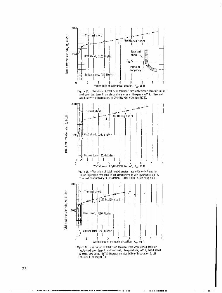
The r e s u l t s of th ree boi loff t e s t s a r e shown i n f igures 14, 15, and 16 where the heat- t ransfer r a t e i s p lo t ted against t he wetted a rea of the cylin- d r i c a l sect ion of the tank. The two runs i n the controlled-environment f a c i l i t y ( f igs . 1 4 and 15) resu l ted i n an average thermal conductivity of 0.096 (Btu) ( in . ) /( hr ) ( s q ft ) ( O F ) .
As shown i n f igures 14, 15, and 16, there i s a large heat short a t the in te rsec t ion of t he bottom dome and the cy l indr ica l sect ion of the insulation. This heat short i s caused by t h e heavy AMA laminate used on the edge of each insulat ion sect ion (see f i g . l ( d ) , p. 5 ) . The heat short w a s calculated t o be 1050 Btu per hour, while t he value, determined by extrapolating the curve (see f i g s . 1 4 t o 1 6 ) and assuming the heat f l u x through the bottom dome the same as i n the cy l indr ica l section, varied from 1000 t o 1340 Btu per hour, depending on ambient conditions. A t 75 percent of tank capacity more than 50 percent of the heat t r ans fe r w a s due t o t h i s heat short . Calculations show t h a t i f Mylar were used instead of the €!MA laminate t o s e a l t he edges of t he insulat ion sec- t i ons , t he heat short t o the l iqu id would be reduced t o approximately 1 Btu per hour.
The outdoor run ( f i g . 16 ) yielded a thermal conductivity K of 0.117 (B tu ) ( in . ) / (h r ) ( sq ft)( 'F) which i s about 15 percent higher than the runs i n the controlled environment. It i s f e l t t h a t t h i s value i s not as accurate as those obtained f r o m t he runs i n the controlled environment f o r the following reasons :
(1) The increase i n f r o s t thickness with time causes the temperature d i f - ference across the insulat ion t o drop during the t e s t . This deviation from thermal e q u i l i b r i m has the e f f ec t of increasing the slope of the Q against Aw plo t . Thus, when the heat f l u x i s determined by the previously described method, it w i l l be higher than t h e ac tua l heat f l u x .
(2) The occasional breakaway of an area of f r o s t and changes i n wind ve loc i ty cause a s c a t t e r i n boi loff data which makes the determination of ther - m a l conductivity more unrel iable . Figure 12 shows the f r o s t formation on the tank during a t e s t . Note the areas of f r o s t that have f a l l e n off and t h a t f r o s t only occurs i n the v i c i n i t y of the heat shorts; t h a t is, the intersect ions of t he the domes with the cylinder.
S t ruc tura l Performance
The tank w a s f i l l e d with l i qu id hydrogen for a t o t a l of 11 hours during the boiloff tests without developing any leaks i n the l i n e r . During t h i s phase of t e s t i n g the tank pressure never exceeded 5 pounds per square inch gage.
21
0 1 2 3 4 5 6 7 8 Wetted area of cylindrical section, &, sq ft
Figure 14. - Variation of total heat-transfer rate with wetted area for liqbid- hydrogen test tank in an atmosphere of dry nitrogen at 65" F. Thermal conductivity of insulation, 0.094 (Btu)(in. )/(hr)(sq ft)("F).
6 7 sq ft
Figure 15. - Variation of total heat-transfer rate with wetted area for liquid-hydrogen test tank i n an atmosphere of d ry nitrogen at 85" F. Thermal conductivity of insulation, 0.097 (BtuNin. )/(hrl(sq ft)("F).
0 1 2 3
-L i
'~ I I I I
1 A
C
h 7 Wetted area of cylindrical sect.-.i, h, sq ft
Figure 16. - Variation of total heat-transfer rate with wetted area for liquid-hydrogen tank in outdoor test. Temperature, 60" F, wind speed 17 mph; dew point, 45" F; thermal conductivity of insulation 0.117 ( BtuXin. )I( h r )(sq ft)("F).
22
I 1 I 1 I I1111IIII. 111
8

Figure 17. - Inside of tank (showing failure i n liner).
Figure 18. - Section of liner material at break.
23

I lll1l111llIll
1- -.=&-- - -*-
I n n e r vacuum jacket ..-I 1 of bleeder ply Glass-cloth bleeder ply
--.. T / ‘l- Unspliced ends
C-69086 Figure 19. - Fai lure in i n n e r vacuum jacket ( l i ne r removed from tank).
70
0 .0002
1
/
/
i k v
/
3/
h Ii
/
/
.Gill0 .0012 Circumferent ia l strain, in./ in.
Tar without l iner (after l iner fai lure)
.0014 .0016 .0018
Figure 20. - Effect of l iner fa i lure on circumferent ia l s t ra in of tank wall.
24

The pressurization tests consisted of 1 cycle to 35 pounds per square inch gage, 2 cycles to 50 pounds per square inch gage, and a finial increase to 68 pounds per square inch gage where liner failure occurred. During the first two cycles, no leaks developed but on the third a very small leak was observed. The leak rate was in the order of cubic centimeters per second at a tank pressure of 50 pounds per square inch gage. As soon as the valve between the insulation and the pump was opened, the pressure in the insulation would drop to less than 5 microns, indicating that this leak presented no pumping problem, The size of this leak did not change even up to the point of liner failure.
Liner failure occurred suddenly with a longitudinal break in the cylindri- Figure 18 shows the brittle fracture of cal section of the tank (see fig. 17).
the Mylar in the liner. the same place. stressed, all adhesive joints remained leak-tight. Upon examination of the inner vacuum jacket it was discovered that the break occurred along the butt joint of the glass-cloth bleeder ply (see fig. 19). vacuum jacket everywhere but at the butt joint where the cloth ends were not spliced, this was the area of highest stress. Instead of the inner vacuum jacket uniformly straining along the entire circumference, most of the expan- sion occurred over the very small length of this maximum stress area. local unit strain was many times higher than it would have been for a uniformly strained material. It is probably the vacuum-jacket failure that initiated the failure in the liner at the same location. It is possible that this failure could have been prevented if the ends of the glass cloth were spliced at the butt joint with a bonded glass-cloth tape.
Both the liner and the inner vacuum jacket failed at It should be noted that, even though the liner was highly
Since the glass-cloth reinforced the
Thus, the
The circumferential strain of the fiber-glass shell was measured during pressure tests of this tank both before and after liner failure. Figure 20 shows a plot of this strain against internal tank pressure. When failure occur- red at' 68.4 pounds per square inch gage, the release of the load carried by the liner and vacuum jacket resulted in increased load on a corresponding strain in the fiber-glass shell. Since the strain at failure, 0.0017 inch per inch, results from a load of only 51.9 pounds per square inch gage after failure, the difference between 68.4 and 51.9 pounds per square inch gage was assumed to be the load the liner and vacuum jacket were taking. Thus, the liner and jacket were taking an internal pressure load of 16.5 pounds per square inch and cor- respondingly stressed to 29 000 pounds per square inch at failure. This is an increase in tensile strength from the 25 000 pounds per square inch at -300' F listed in table I. The 51.9 pounds per square inch gage carried by the fiber- glass shell results in a composite wall stress of 12 000 pounds per square inch, well below its ultimate of 120 000 pounds per square inch.
Final examination of the tank revealed the existance of wrinkles indicating the liner and inner vacuum jacket material has been stressed beyond its elastic limit and thus has taken a permanent set in spite of prestressing the AMA lami- nate. It was found. that the wrinkles in the vacuum jacket (see fig. 21) are not sharply creased as in the preliminary liner tests but rather they are rounded and not likely to be leak sources. It appears that the glass cloth and foam help stabilize the wrinkles and prevent the formation of sharp creases.
25

C-69087
Figure 21. - Inner vacuum jacket after testing.
CONCLUDING REMARKS
A leak t i g h t , i n t e rna l ly insulated, f iber -g lass tank f o r l iqu id hydrogen w a s b u i l t under the present s t a t e of the art . The r e s u l t s of the s t r u c t u r a l t e s t s indicate t h a t adhesive-bonded jo in t s a r e capable of maintaining vacum- t i g h t sea ls under cryogenic conditions. This indicates t h a t i n the fu ture more advantage can be taken of adhesives i n the f i e l d of cryogenics.
I n general, the results of t he t e s t s run on the subscale tank were encour- aging. shorts a t the in te rsec t ions of t he domes and. the cy l indr ica l section. These heat shorts a r e not inherent i n t h i s type of system and can e a s i l y be eliminated. There a re no heat shorts due t o s t ruc tu ra l supports penetrating the insulat ion as i n external insu la t ion systems.
The insu la t ion system performed well with the exception of thermal
The heat f l u x through the l/Z-inch th ick insu la t ion w a s about 90 Btu/ ( h r ) ( s q f t ) . The corresponding thermal conductivity i s 0.096 (Btu) ( in . ) / ( h r > ( s q f t> (OF>*
The concept of i n t e rna l insulat ion seems t o be promising. l imi ta t ion i s t h a t t he insu la t ion must be able t o withstand a compressive s t r e s s equal t o the i n t e r n a l pressure of the tank. on boost vehicles t h i s does not appear t o be a serious l imitat ion.
An inherent
For insulat ions of the type used
Although the l i n e r f a i l e d a t approximately 70 pounds per square inch gage, 30 percent below the design pressure of 100 pounds per square inch, t h i s i s a s ignif icant f i rs t s tep i n the development of a successful l i ne r . With simple changes i n construction, for instance, correcting the l o c a l s t ra ining of the jacket a t the bleeder p l y jo in t , the working pressure of t h i s tank could be subs tan t ia l ly increased. reduced the amount of permanent s e t and r e su l t i ng wrinkles, some did occur.
Although the prestressing of the l i n e r mater ia l
26

With a t o t a l composite s t r e s s of only 1 2 000 pounds per square inch i n the cy l indr ica l wall, t h i s tank i s only about one t en th of the f u l l po ten t ia l of f i b e r glass. The l i n e r must be capable of expanding more i f f i b e r glass i s going t o be used t o f u l l advantage. The solut ion of t he problem of ge t t ing the l i n e r t o s t r a i n as much as the f i b e r glass by allowing it t o yield and thus wrinkle seems t o be the best approach. The wrinkles must be s t ab i l i zed t o prevent sharp creases and improve cycling l i f e . A promising method of s t a b i l i z - ing these wrinkles i s to bond a c lo th t o one or both s ides of the l i ne r . The c lo th should have a very e l a s t i c type of weave and probably an organic f ibe r . It seems l i k e l y t h a t t he wrinkles can be put i n while t he tank i s a t room tem- perature by pressurizing t o near the burst point. Future e f f o r t i n t h i s area i s required.
Lewis Research Center, National Aeronautics and Space Administration,
Cleveland, Ohio, May 27, 1965.
27
.- . ~ ~- ,.. ,.....,I,. ,,,,,-. _... . -.,_. , .. .

A
E
G
hfg
K
il
P
Q R
S
m
t
v
.iT Ax
E
P
APPENDIX - SYMBOLS
area, cu f t
modulus of e l a s t i c i t y , lb/sq in .
gas meter reading, cu f t
heat of vaporization of liquid-hydrogen, Btu/lb m
thermal conductivity of insulat ion, (Btu) ( in . )/(hr)( s q f t ) (bF)
mass flow r a t e , l b m/sec
in t e rna l pressure, lb/sq in.
t o t a l heat t r ans fe r r a t e t o l iqu id , Btu/hr
radius, i n .
hoop s t r e s s , lb/sq in .
temperature difference, OF
hoop ,material thickness, in .
volume, cu f t
volume flow r a t e , cu f t / s e c
knsulation thickness, in .
un i t s t r a i n , in. / in.
density, l b m/cu f t
Subscripts :
f f i n a l
G boi loff gas
I l iqu id vapor in te r face
L li qui2
E l i n e r
S thermal l i n e r
W wetted surface
28

1. Morris, Edgar E.: Glass Cases for the Biggest Solids. Astronautics and Aeronautics, vol. 2, no. 7, July 1964, pp. 28-38.
2. Hickel, Robert 0.; Johnson, Donald F.; and Kmp, Richard H.: A Summary of the Behavior of Materials at Cryogenic Temperatures. Quarterly, vol. 3, no. 2, May 1963, pp. 18-28.
Metals Eng.
3. Hanson, Morgan P.; Richards, Hadley T.; and Hickel, Robert 0.: Preliminary Investigation of Filament-Wound Glass-Reinforced Plastics and Liners for Cryogenic Pressure Vessels. NASA TN D-2741, 1965.
4. Shriver, C.. B.: Design and Fabrication of an Internally Insulated Filament Wound Liquid Hydrogen Propellant Tank. NASA CR-127, 1964.
5. Hacker, Paul T.; DeVos, Francis J.; and Stutesman, Harley: Evaluation of Adhesives for Sealing Metallic and Plastic Films for Use at Liquid- Hydrogen Temperatures. NASA TM X-1057, 1965.
NASA-Langley, 1965 E-2794 29