
Evaluation of a BOF Slag Recovery Treatment combining...
32
Evaluation of a BOF Slag Recovery Treatment combining Experimental and Simulation Studies Ismael Matino 1 , Teresa Annunziata Branca 1 , Erika Alcamisi 1 , Valentina Colla 1 , Lea Romaniello 2 1 Scuola Superiore Sant’Anna, TeCIP Institute, Pisa, Italy Corresponding autor: Ismael Matino, Scuola Superiore Sant’Anna, TeCIP Institute, 56010 Ghezzano,Pisa, Italy. Email: [email protected] 2 ILVA S.p.A. , Taranto Works, Taranto, Italy Abstract Industrial waste and by-products can be thought as important sources to be recovered. From an environmental point of view, instead of disposal, different treatments can be considered to obtain products for new applications. The large amount of by-products and wastes produced by the steel industry justifies the efforts in management and recovery to enhance sustainability. Basic Oxygen Furnace slag is an example of steel by-product, which reuse and recycle options are supported by suitable chemical composition according to internal and external plant requirements. The paper presents the investigation about feasibility of a possible Basic Oxygen Furnace slag recovery treatment, by combining experimental and simulation tests.
Transcript of Evaluation of a BOF Slag Recovery Treatment combining...
Evaluation of a BOF Slag Recovery Treatment combining
Experimental and Simulation Studies
Ismael Matino1, Teresa Annunziata Branca1, Erika Alcamisi1, Valentina Colla1,
Lea Romaniello2
1 Scuola Superiore Sant’Anna, TeCIP Institute, Pisa, Italy
Corresponding autor:
Ismael Matino, Scuola Superiore Sant’Anna, TeCIP Institute, 56010 Ghezzano,Pisa,
Italy.
Email: [email protected]
2 ILVA S.p.A. , Taranto Works, Taranto, Italy
Abstract
Industrial waste and by-products can be thought as important sources to be
recovered. From an environmental point of view, instead of disposal, different
treatments can be considered to obtain products for new applications. The large
amount of by-products and wastes produced by the steel industry justifies the efforts
in management and recovery to enhance sustainability. Basic Oxygen Furnace slag is
an example of steel by-product, which reuse and recycle options are supported by
suitable chemical composition according to internal and external plant requirements.
The paper presents the investigation about feasibility of a possible Basic Oxygen
Furnace slag recovery treatment, by combining experimental and simulation tests.

Chemical analyses have been carried out to characterize the slag, which is proposed
to be firstly cooled and ground and sieved to release the slag phases with different
magnetic properties. Experimental and simulation studies allow verifying slag reuse
possibility and identifying the parameters that mostly affect the treatment efficiency.
The obtained final fractions appear to be possibly suitable for reuse as fertiliser
and pellettization operations, with adjustments in magnetic separation operation.
Model can be used for different slag qualities and different treatments operating
conditions.
Keywords
BOF Slag, Waste Management, By-Product Recovery, Process Modelling, Process
Simulation
Introduction
In the last few years, the international community has become increasingly
sensitive to environmental issues as well as landscape and health protection. Even
more stringent legislation and the increase of landfill and disposal costs have led to
employ greater efforts to improve the recycling and the reuse of waste and by-
products and consequently to minimize landfills (European Commission 2008).
Regarding the steel industry, several investigations about enhancements of waste
and by-products management and recycling have been carried out (Matino et al. 2014,
Das et al. 2007). Different factors affect the recycling rate of by-products, such as
environmental requirements, energy use and economical and technological feasibility,
and for this reason process integration model can be used with the aims of improving
the material and energy efficiency, together with environmental or economic
sustainability for the steel production system (Larsson et al. 2006).In effect, during
ironmaking and steelmaking operations, along with hot metal and steel products, some
different types of by-products are generated, i.e. slags, dusts, sludges and mill scales,
where slags represent almost the 90% of the total amount. The multitude of kinds can
result in various reuse options and, for this reason, over the past decadesthe steel
industry has been committed to increase by-products recovery rateby developing
innovative technologies. The recycle options are not only the external use in other
industries or field of applicationsas construction material, road building, concrete
aggregate and thermal insulation, but also the internal reuse in ironmaking and
steelmaking processesas raw materials, justified by the high content of valuable
elements, such as iron (World Steel Association 2010).Any of these recoveryoption
guides to reducing landfill waste, CO2 emissions and to the exploitation of natural
resources but also to revenues, which make the by-products recycling economically
sustainable (World Steel Association 2015). The innovation to traditional process
technologies, demanded to the steel industry, has the objective to match the
requirements of high competitiveness, due to high costs, raw material shortages,
environmental issues and customer demands. The aims arethe improvements of steel
properties and qualities and, last but not least,the achievement of a better knowledge
related to by-products.
Specific attention has to be paid on slags recycling and especially on theslags role
as valuable resources,because of the large volumes (more than 400 Mt) produced
worldwide (World Steel Association 2010).In effect, also focusing on the only slag as
by-product a large variety can be identified and in particular Blast Furnace (BF) slag,
Basic Oxygen Furnace (BOF) slag, Electric Arc Furnace (EAF) slag and Secondary

Metallurgical (SM) slag can be mentioned (The European Slag Association 2012).
Someof them, such as BOF slag and EAF slag, are produced in the primary
steelmaking stage, respectively from the conversion of hot metal to steel and from
melting scrap operations. The addition of smelting, slagging agents and fluxes into
furnaces, such as limestone, dolomite and silica sand, after removing impurities from
metal baths, forms slags that protect liquid metal,maintaining the temperature value.
In secondary steelmaking refining operations,other slags are generated, such as SM
and Ladle Furnace (LD) slags, due to the addition of alloys and fluxes, in order to
produce different steel grades.
Slags main components are silica, calcium oxide, magnesium oxide and aluminium
and iron oxides and due to the high content of iron (10 – 40% in weight of metal iron,
excluding iron oxides) and iron oxides, steelmaking slags can be used as a potential
renewable resource.Nevertheless, different conditions during operations result in
slagsdifferent chemical compositions, mineralogyand physical properties are the
discriminating factor for fate as waste or reusable product.
A deep understanding regarding the nature of slags can allow improvingthe recycle
and the reuse with a significant reduction in the related environmental
impact(Dippenaar et al. 2005).This objective justifies some innovative studies,focused
on the characterization of slags. For instance,BOF slag can be used asreactant for the
CO2chemical absorption for carbon sequestration from the steel industry (Birat et al.
2009). On the other hand, the content of calciumsilicates, carbonates, and oxides
makes it suitable for agriculture purposes, in the case of proved negligible content of
trace elements, such as heavy metals, which can be released and leached to surface
water.

For this reason, the assessment of chemical and physical characteristics under
natural and simulated conditions is the preliminary step to evaluate the potential
environmental impacts associated with slagapplication, in agriculture such as in
construction or other fields(Proctor et al. 2000). In order to assess the possible use of
BOF slag in agriculture for amending purposes, the effects and possible risks by using
slags in two moderately alkaline soils through a soil infiltration column test have been
investigated (Pistocchi et al. 2012). Different effects as well as different soils in
Europe have been analysed in order to test the use of slags. On one
hand,investigations have concerned the use as liming material in the long-term field
trials, for preventing acidification in Middle Europe soils. On the other hand,tests have
been carried out to assess the effect of Ca contained in BOF slag for balancing
negative Na effects in alkaline Mediterranean soils, characterized by seawater
intrusion and irrigation with saline water (Branca et al. 2014).
Usually slag management includes different operations, such as dumping on a
waterproof surface, cooling, crushing, grinding and sieving, to obtain a good magnetic
separation. After tapping and discharging from the equipment, once slag is cooled and
solidified under atmospheric conditions and after crushing, the metallic fractionis
removed by magnetic cylinders and the nonmetallic part of slag is crushed and sieved
for recycling later. Some studies have been carried out in order to reduce dust
emissions coming from SM slag management, focusing on LD slag, due to instability
of dicalcium silicate content, whichcan cause environmental impact, and to make
slagsuitable for further applications(Branca et al. 2009).
Regarding BOF slags, experimental studies include magnetic separator
beneficiation parameters, chemical and mineralogical properties, metallurgical
properties and their optimum combination. As far as the BOF slag processing is
concerned, the goal consists in achieving a product with high iron content,with the
final objective of slag reuse in sintering process. The iron separation from slag allows
ironrecovering as a substitute for scrap, as well as making effective use of the slag for
other applications, where iron would be an impurity. This is the reason why, after
cooling, the steel slags are ground and the iron recovered by magnetic separation
(Horii et al. 2012). The connection between iron recovery ratio and cooling conditions
by applying wet magnetic separation has been investigated (Wang et al. 2012).
Recently, a cleaner iron-rich product with low impurities has been obtainedby coupling
weak magnetic separation with selective size screening on steelmaking slag fines.
This fractioncouldbe consequently senttodifferent unit operations of ironmaking and
steelmaking route, increasing the recycling rate of slags (Ma et al. 2014), or classified
as a recyclable not hazardous waste.
This paper fits in withthe BOF slag management, treatment and recovery option.
The development of an Excel-based model is presented, to simulate theproposed
treatment process, by combining experimental data and process modelling, providing
a preliminary proof of BOF slag reuse. BOF slag supplied by ILVA Steelworks has
been subjected to a treatment process including anair-cooling stage, grinding and
sieving stage and a magnetic separation of the coarse fraction. The obtained magnetic
fraction, mixed with the fine fraction, will be tested for the use in sinter plant while the
non-magnetic fraction will be tested for the use as fertiliser.
In the first section ofMaterial and methods, experimental studies and process
modelling are presented. The developed model has been applied to one specific case
study and the Results and discussion section highlights the obtained outcomes.

Finally, the Conclusionsection illustrates the guidelines deduced by experimentation
and simulation tests.
Materials and Methods
The investigation of BOF slag recovery requires several studies to obtain information
about slag features andtreatment process to recover slag fractions. The exploitation of
both experimental and simulation results can be useful to achieve the objective of
obtaining suitable slag fractions to be reused.
Starting from literature and heuristic information, a recovery optionhas been
proposed, based on several slag physical treatments (Fig. 1).
Figure1. BOF slag proposed recovery treatment.
The hot slag coming from Basic Oxygen Furnace is subjected to an initial step of
cooling. Then it is ground and sievedto release the slag phases with different
magnetic properties and to obtain two main fractions with suitable particle size
distributions (PSD). A magnetic separation is carried out for iron removal on the
coarse fraction (supposed to be richer in iron). The not-magnetic fraction is re-milled
to obtain a suitable PSD for the possible reuse as fertiliser (PSD<1mm).
The paragraph describes experimental studies in order to characterize the BOF
slag and preliminary laboratory tests of the proposed process. All the obtained
information have been used to model the selected treatment using the approach
presented in the following sections.
Simulation outputs can provide preliminary information of BOF slag reuse feasibility
in terms of suitability of final slag fractions features.
Experimentation
Experimental studies arenecessary to demonstrate the suitability of BOF slag
assecondary raw material (e.g. as fed to sinter plant or as fertiliser) after adhoc
recovery treatment.Tests took place in Taranto ILVA plant, organized in two main
tasks:
• BOF slag characterization, to obtain useful information for the next steps;
• laboratory scale tests, to deduce important guidelines for analysis and
implementation of the proposed slag treatment.
BOF slag characterization
Three quality types of slag were selected in Taranto steelworks, each regarding the
production of a different steel grade, and several samples for each kind of slag have
been characterized.
The reference compositions related to the considered slags are highlighted in Table
1while the sizes and appearances of two of them are shown in Fig. 2.
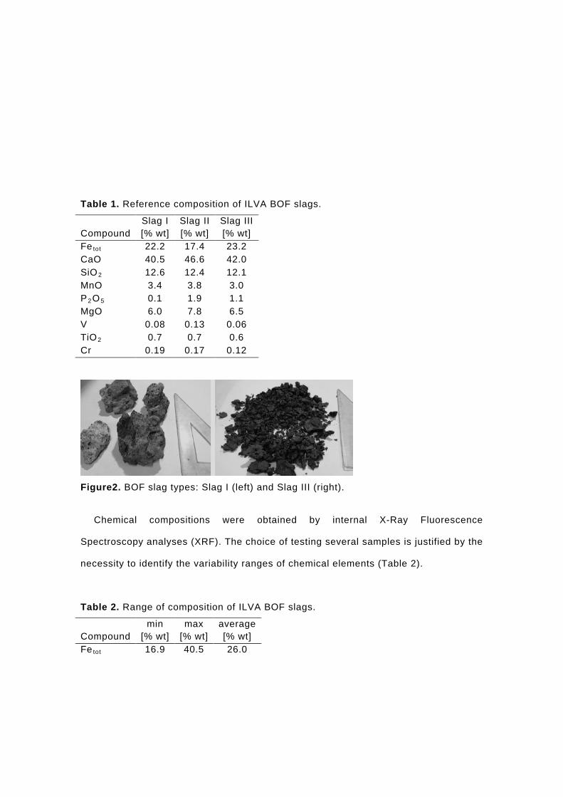
Table 1. Reference composition of ILVA BOF slags.
Compound Slag I [% wt]
Slag II [% wt]
Slag III [% wt]
Fe tot 22.2 17.4 23.2 CaO 40.5 46.6 42.0 SiO2 12.6 12.4 12.1 MnO 3.4 3.8 3.0 P2O5 0.1 1.9 1.1 MgO 6.0 7.8 6.5 V 0.08 0.13 0.06 TiO2 0.7 0.7 0.6 Cr 0.19 0.17 0.12
Figure2. BOF slag types: Slag I (left) and Slag III (right).
Chemical compositions were obtained by internal X-Ray Fluorescence
Spectroscopy analyses (XRF). The choice of testing several samples is justified by the
necessity to identify the variability ranges of chemical elements (Table 2).
Table 2. Range of composition of ILVA BOF slags.
Compound min
[% wt] max
[% wt] average [% wt]
Fe tot 16.9 40.5 26.0
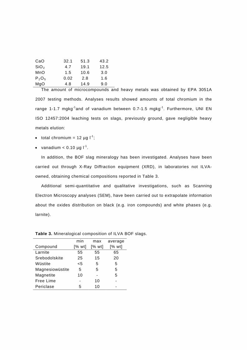
CaO 32.1 51.3 43.2 SiO2 4.7 19.1 12.5 MnO 1.5 10.6 3.0 P2O5 0.02 2.8 1.6 MgO 4.8 14.9 9.0
The amount of microcompounds and heavy metals was obtained by EPA 3051A
2007 testing methods. Analyses results showed amounts of total chromium in the
range 1-1.7 mgkg-1and of vanadium between 0.7-1.5 mgkg-1. Furthermore, UNI EN
ISO 12457:2004 leaching tests on slags, previously ground, gave negligible heavy
metals elution:
• total chromium = 12 µg l-1;
• vanadium < 0.10 µg l-1.
In addition, the BOF slag mineralogy has been investigated. Analyses have been
carried out through X-Ray Diffraction equipment (XRD), in laboratories not ILVA-
owned, obtaining chemical compositions reported in Table 3.
Additional semi-quantitative and qualitative investigations, such as Scanning
Electron Microscopy analyses (SEM), have been carried out to extrapolate information
about the oxides distribution on black (e.g. iron compounds) and white phases (e.g.
larnite).
Table 3. Mineralogical composition of ILVA BOF slags.
Compound min
[% wt] max
[% wt] average [% wt]
Larnite 55 55 65 Srebodolskite 25 15 20 Wüstite <5 5 5 Magnesiowüstite 5 5 5 Magnetite 10 - 5 Free Lime - 10 - Periclase 5 10 -
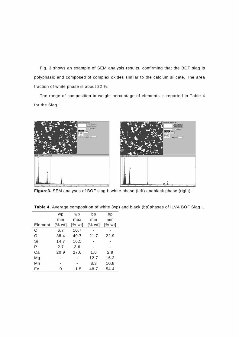
Fig. 3 shows an example of SEM analysis results, confirming that the BOF slag is
polyphasic and composed of complex oxides similar to the calcium silicate. The area
fraction of white phase is about 22 %.
The range of composition in weight percentage of elements is reported in Table 4
for the Slag I.
Figure3. SEM analyses of BOF slag I: white phase (left) andblack phase (right).
Table 4. Average composition of white (wp) and black (bp)phases of ILVA BOF Slag I.
Element
wp min
[% wt]
wp max
[% wt]
bp min
[% wt]
bp min
[% wt] C 6.7 10.7 - - O 38.4 49.7 21.7 22.9 Si 14.7 16.5 - - P 2.7 3.6 - - Ca 20.9 27.6 1.6 2.9 Mg - - 12.7 16.3 Mn - - 8.3 10.8 Fe 0 11.5 48.7 54.4
Slag grain sizedistribution has been examined by physical analyses (ISO
4701:2008).
The chemical characterization demonstrates that calcium and iron are the main
slag components. Other interesting compounds such as phosphorous oxides make
BOF slag potentially suitable as secondary raw material (e.g. fertiliser).
Adhoc physical treatments can be required to separate slag in its two main
fractions, the iron-rich one, to be fed in sinter plant, and the calcium-and-phosporous-
rich, to be used as fertiliser.Heavy metals content is negligible as well as the leaching
behaviour.
Laboratory scale test
Preliminary laboratory scale tests have been carried out to confirm the suitability of
the proposed procedure to separate solid slag into two main fractions, one richerand
one poorer in iron. The tests have been carried out on different slag qualities.
The BOF slagshave been sampled after an air-cooling stage of 24 hours at
atmospheric temperature and pressure. The samples have been aged for some days
and then subjected to milling and sieving processes.
The grinding step has been executed in a lab jaw crusher equipment, resulting in two
main fractions, one coarse (PSD >1mm) and one finer (PSD<1 mm). In this lab tests,
the slag appeared brittle with negligible ductile metallic iron.
Each obtained fraction has beentreated by manual magnetic separation, using a
neodymium magnetupon a thin layer of slag.
The two parts coming from the finer fraction have been analysed but presented
similar iron content. This could be justified by not suitability of manual magnetic
separation, as the iron particles are bonded to the fine grainsof slag.
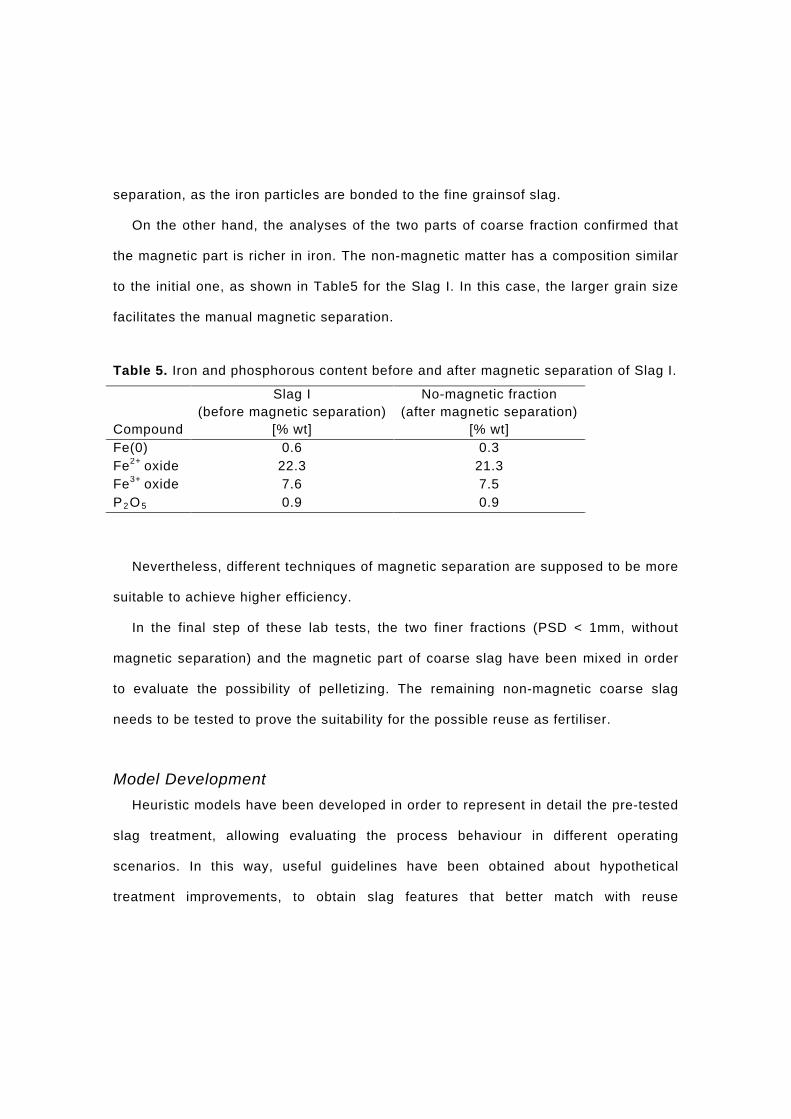
On the other hand, the analyses of the two parts of coarse fraction confirmed that
the magnetic part is richer in iron. The non-magnetic matter has a composition similar
to the initial one, as shown in Table5 for the Slag I. In this case, the larger grain size
facilitates the manual magnetic separation.
Table 5. Iron and phosphorous content before and after magnetic separation of Slag I.
Compound
Slag I (before magnetic separation)
[% wt]
No-magnetic fraction (after magnetic separation)
[% wt] Fe(0) 0.6 0.3 Fe2+ oxide 22.3 21.3 Fe3+ oxide 7.6 7.5 P2O5 0.9 0.9
Nevertheless, different techniques of magnetic separation are supposed to be more
suitable to achieve higher efficiency.
In the final step of these lab tests, the two finer fractions (PSD < 1mm, without
magnetic separation) and the magnetic part of coarse slag have been mixed in order
to evaluate the possibility of pelletizing. The remaining non-magnetic coarse slag
needs to be tested to prove the suitability for the possible reuse as fertiliser.
Model Development Heuristic models have been developed in order to represent in detail the pre-tested
slag treatment, allowing evaluating the process behaviour in different operating
scenarios. In this way, useful guidelines have been obtained about hypothetical
treatment improvements, to obtain slag features that better match with reuse
suitability.
The model can be used to simulate different case studies, varying BOF slag
qualities (chemical and mineralogical composition, particle size distribution, etc.) and
operating conditions of treatment units, as simultaneous, auxiliary and complementary
support for lab tests instead of executing plant on-line applications.
The outputs, i.e. slag fractions characteristics, can be analysed in order to evaluate
possible reuse feasibility as raw materials in other contexts.
The developed Excel-based model includes sub-models related to the main stages
of the proposed BOF slag treatment, as follows:
• cooling stage;
• grinding and sieving;
• magnetic separation.
Literature and real data obtained in the preliminary experimentation and lab tests
are the required information for tuning and validation steps, which the models are
based on.
Cooling Stage Sub-Model
BOF slags coming from the process are very hot (T≈1600°C). A cooling stage is
essential before any hypothetic treatment to avoid equipment damages.
The developed cooling sub-models is able to estimate the final slag temperature,
taking into account each involved phenomena, in order to monitor time temperature
and heat losses on the basis of the cooling time. Slag has been discretised in layers
with computed temperatures.
Useful guidelines on energy contributions can be obtained, aimed at the
investigation on the eventual possibility of recovery.
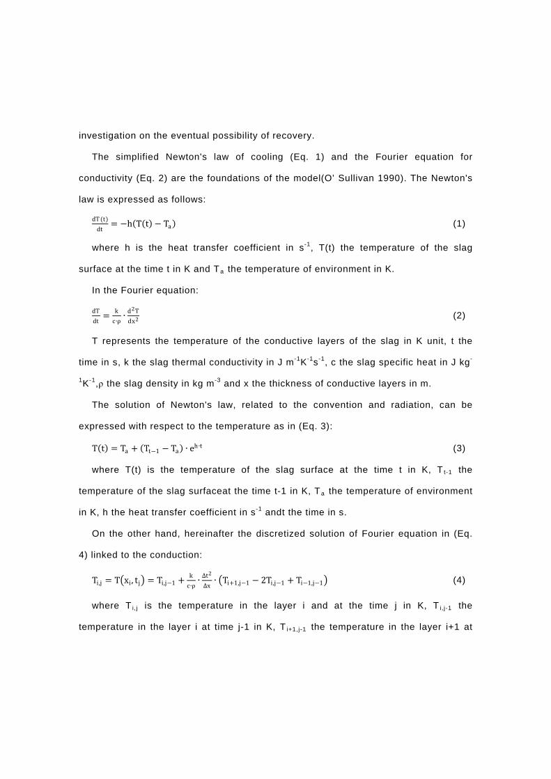
The simplified Newton's law of cooling (Eq. 1) and the Fourier equation for
conductivity (Eq. 2) are the foundations of the model(O’ Sullivan 1990). The Newton's
law is expressed as follows:
dT (t)dt
= −h(T(t) − Ta) (1)
where h is the heat transfer coefficient in s-1, T(t) the temperature of the slag
surface at the time t in K and Ta the temperature of environment in K.
In the Fourier equation:
dTdt
= kc∙ρ∙ d2T
dx2 (2)
T represents the temperature of the conductive layers of the slag in K unit, t the
time in s, k the slag thermal conductivity in J m-1K-1s-1, c the slag specific heat in J kg-
1K-1,ρ the slag density in kg m-3 and x the thickness of conductive layers in m.
The solution of Newton's law, related to the convention and radiation, can be
expressed with respect to the temperature as in (Eq. 3):
T(t) = Ta + (Tt−1 − Ta) ∙ eh∙t (3)
where T(t) is the temperature of the slag surface at the time t in K, T t-1 the
temperature of the slag surfaceat the time t-1 in K, Ta the temperature of environment
in K, h the heat transfer coefficient in s-1 andt the time in s.
On the other hand, hereinafter the discretized solution of Fourier equation in (Eq.
4) linked to the conduction:
Ti,j = T�xi, tj� = Ti,j−1 + kc∙ρ∙ ∆t2
∆x∙ �Ti+1,j−1 − 2Ti,j−1 + Ti−1,j−1� (4)
where T i,j is the temperature in the layer i and at the time j in K, T i,j-1 the
temperature in the layer i at time j-1 in K, T i+1,j-1 the temperature in the layer i+1 at
time j-1 in K, T i-1,j-1 the temperature in the layer i-1 at time j-1 in K, k the slag thermal
conductivity in J m-1 K-1 s-1, c the slag specific heat in J kg-1 K-1, ρ the slag density in
kg m-3, Δt the magnitude of discretized time period in s and Δx the thickness of each
conductive layer in internal fraction of slag in m.
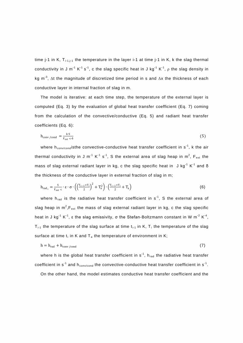
The model is iterative: at each time step, the temperature of the external layer is
computed (Eq. 3) by the evaluation of global heat transfer coefficient (Eq. 7) coming
from the calculation of the convective/conductive (Eq. 5) and radiant heat transfer
coefficients (Eq. 6):
hconv /cond = k∙SFext ∙c∙δ
(5)
where hconv/cond isthe convective-conductive heat transfer coefficient in s-1, k the air
thermal conductivity in J m-1 K-1 s-1, S the external area of slag heap in m2, Fext the
mass of slag external radiant layer in kg, c the slag specific heat in J kg-1 K-1 and δ
the thickness of the conductive layer in external fraction of slag in m;
hrad i = SFext ∙c
∙ ε ∙ σ ∙ ��Ti−1+Ti2
�2
+ Ta2� ∙ �Ti−1+Ti
2+ Ta� (6)
where h rad is the radiative heat transfer coefficient in s-1, S the external area of
slag heap in m2,Fext the mass of slag external radiant layer in kg, c the slag specific
heat in J kg-1 K-1, ε the slag emissivity, σ the Stefan-Boltzmann constant in W m-2 K-4,
T i-1 the temperature of the slag surface at time t i-1 in K, T i the temperature of the slag
surface at time t i in K and Ta the temperature of environment in K;
h = hrad + hconv /cond (7)
where h is the global heat transfer coefficient in s-1, h rad the radiative heat transfer
coefficient in s-1 and hconv/cond the convective-conductive heat transfer coefficient in s-1.
On the other hand, the model estimates conductive heat transfer coefficient and the

temperature value of each internal conductive layer of the BOF slag on the basis of
Fourier equation (Eq. 4).
To summarize, the global mass of residue is preliminary divided in several layers.
Then, given an initial hot slagtemperature, atmospheric temperature and a user
specified cooling time, the model gives the external slag temperature and the internal
core ones as outputs.Heat losses are also estimated by the model, as in Table 6.
The height of slag heap is an approximate value but fundamental for the cooling
model, which main sheet is shown in Fig.4.
Table 6. Input and Output of Cooling Stage Model.
ID Variables Unit Type F Inlet mass kg IN Tin Initial slag temperature °C IN Ta Atmospheric temperature °C IN h Height of slag heap m IN t Cooling time min IN PM Slag mean molar weight g mol-1 REF rho Slag density kg m-3 REF ε Slag emissivity REF c Slag specific heat J mol-1K-1 REF kslag Slag conductivity J mol-1 K-1 s-1 REF K Air thermal conductivity J mol-1 K-1 s-1 REF σ Stefan-Boltzmann constant W m-2 K-4 REF
δ Thickness of the conductive layer in external fraction of slag m REF
s Thickness of each conductive layer in internal fraction of slag m REF
Tcore Final temperature of core slag °C OUT Text Final temperature of external slag °C OUT Qloss Heat Losses GJ OUT
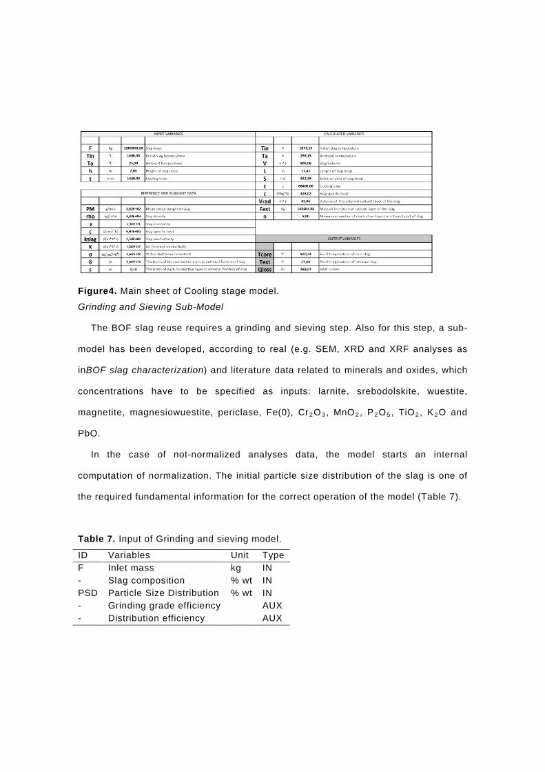
Figure4. Main sheet of Cooling stage model.
Grinding and Sieving Sub-Model
The BOF slag reuse requires a grinding and sieving step. Also for this step, a sub-
model has been developed, according to real (e.g. SEM, XRD and XRF analyses as
inBOF slag characterization) and literature data related to minerals and oxides, which
concentrations have to be specified as inputs: larnite, srebodolskite, wuestite,
magnetite, magnesiowuestite, periclase, Fe(0), Cr2O3, MnO2, P2O5, TiO2, K2O and
PbO.
In the case of not-normalized analyses data, the model starts an internal
computation of normalization. The initial particle size distribution of the slag is one of
the required fundamental information for the correct operation of the model (Table 7).
Table 7. Input of Grinding and sieving model.
ID Variables Unit Type F Inlet mass kg IN - Slag composition % wt IN PSD Particle Size Distribution % wt IN - Grinding grade efficiency AUX - Distribution efficiency AUX

The main sheet of the proposed model is shown in Fig.5.
A heuristic approach for the grindability of a specific mineral has been considered:
particle size and grindinggrade and distribution efficiencies are specified and fixed,
based on collected tenacity and hardness (Mohs scale) values and work index of each
slag compounds(Mindat, Mineral Data Publishing 2001-2005, Tsakalis).
A global overview for the model operating principle can be described as follows:
starting from an initial slag composition and PSD, the model uses fixed grinding grade
and distribution efficiencies respectively to reduce the BOF slag size by specific
factors, allocating each fraction in the relative partition of the new particle size
distribution.

Figure 5. Main sheet of Grinding and sieving model.

The composition of each fraction is provided, as shown in Figure 5. The model
gives also anestimation of mill energy consumption based on Bond's law of
comminution(Saeidi et al. 2013, Venkateswaran 2007):
W = 10Wi ∙ �1
�P80− 1
�F80� (8)
where W is the predicted mill energy consumption in kWh ton-1, Wi the work index
in kWh ton-1, P80 the 80% passing size in µm of product and F80 the 80% passing size
in µm of feed.
The outputs of the model are listed in the Table 8.
Table 8. Output of Grinding and sieving model.
Variables Unit Output PSD (fraction) % wt Output PSD (mass) kg Composition of each particle size fraction % wt Mass of each particle size fraction kg
Magnetic Separation Sub-Model
Magnetic separation is the final treatment stage to separate from BOF slag a
magnetic and iron rich fraction, potentially suitable for sintering process, and a non-
magnetic fraction.
Fig. 6 highlights the third sub-model related to this treatment.
As in the previous grinding and sieving model, the composition of BOF slag in
terms of common minerals and oxides are input for the model.
Literature information about magnetic properties of slag compounds have been
used to estimate separation efficiencies between magnetic and non-magnetic
fractions(Mindat, Mineral Data Publishing 2001-2005).
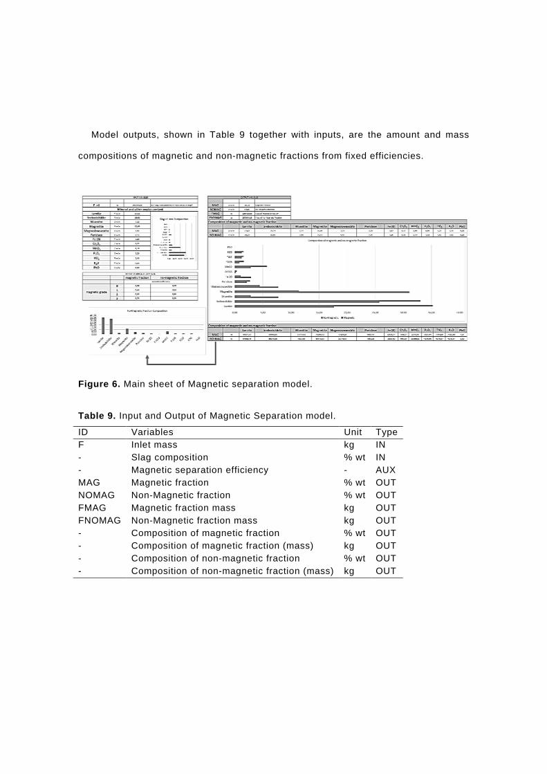
Model outputs, shown in Table 9 together with inputs, are the amount and mass
compositions of magnetic and non-magnetic fractions from fixed efficiencies.
Figure 6. Main sheet of Magnetic separation model.
Table 9. Input and Output of Magnetic Separation model.
ID Variables Unit Type F Inlet mass kg IN - Slag composition % wt IN - Magnetic separation efficiency - AUX MAG Magnetic fraction % wt OUT NOMAG Non-Magnetic fraction % wt OUT FMAG Magnetic fraction mass kg OUT FNOMAG Non-Magnetic fraction mass kg OUT - Composition of magnetic fraction % wt OUT - Composition of magnetic fraction (mass) kg OUT - Composition of non-magnetic fraction % wt OUT - Composition of non-magnetic fraction (mass) kg OUT
Results and discussion
Case Studies simulation
The developed models are useful to analyse the proposed treatment behaviour with
different quality of BOF slag or under different operating conditions in order to obtain
final slag featuresto reinforce/attenuate the hypothesis of the internal or external
reuse and recycle.
Each described sub-model of the whole treatment process has been tested for one
case study, presented hereinafter regarding one kind of BOF slag quality: initial
models outputs were foundto be similar with data from preliminary lab tests.
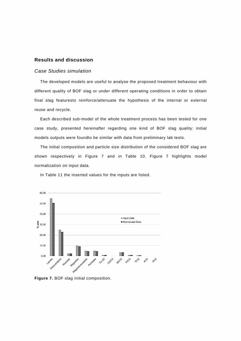
The initial composition and particle size distribution of the considered BOF slag are
shown respectively in Figure 7 and in Table 10. Figure 7 highlights model
normalization on input data.
In Table 11 the inserted values for the inputs are listed.
Figure 7. BOF slag initial composition.
Table 10. BOF slag initial PSD.
mm mm % wt < 0.063 0.00 0.063 0.106 0.00 0.106 0.125 0.00 0.125 0.15 0.00 0.15 0.212 0.00 0.212 0.25 0.00 0.25 0.5 0.00 0.5 1 0.00 1 1.4 0.10 1.4 2 0.10 2 2.36 0.10 2.36 2.8 0.20 2.8 3.35 0.10 3.35 4 0.30 4 4.75 0.10 4.75 6.3 1 6.3 8 2 8 9.5 20.20 9.5 10 11.60 10 16 39.40 > 16 24.80
Table 11. Model global input.
Input Data Unit Value Mass of the slag to be treated t 2000 Initial slag temperature °C 1600 Atmospheric temperature °C 25 Initial slag PSD % wt Table 10 Slag composition %wt Figure 7
For the first stage a cooling time of 24 hours at atmospheric temperature and
pressure has been considered, obtaining an external BOF temperature of 25°C,
according to real data. The model provides also a temperature value of about 920° C
for the internal core of the slag and heat losses of about 488 GJ: possibilities for

energy recovery can be evaluated.
The results obtained after grinding and sieving steps are shown in Table 12 and
Figure 8, respectively the PSD of treated slag after grinding and the composition of
each particle size fraction.
Table 12. BOF slag final PSD.
mm mm % wt < 0.045 6.38 0.045 0.063 7.20 0.063 0.09 7.04 0.09 0.125 8.92 0.125 0.25 11.78 0.25 0.5 13.40 0.5 0.8 13.52 0.8 1 6.97 > 1 24.79
Figure 8. Composition of each particle size fraction of slag after grinding and sieving.
It is clear that fractions with PSD lower than 0.25 mm are richer in calcium
compounds and poorerin ferrous compounds if compared with the other bigger
fractions, richer in phosphorus. An estimated mill energy of about 17,5 MWh are
necessary to grind the considered mass of slag.
According to the proposed global treatment, only the coarse fraction is fed to the
magnetic separation.
The sub-model for this step divides the coarse slag in the following fractions:
• 46 % wt. of magnetic fraction;
• 54 % wt. ofnon-magnetic fraction.
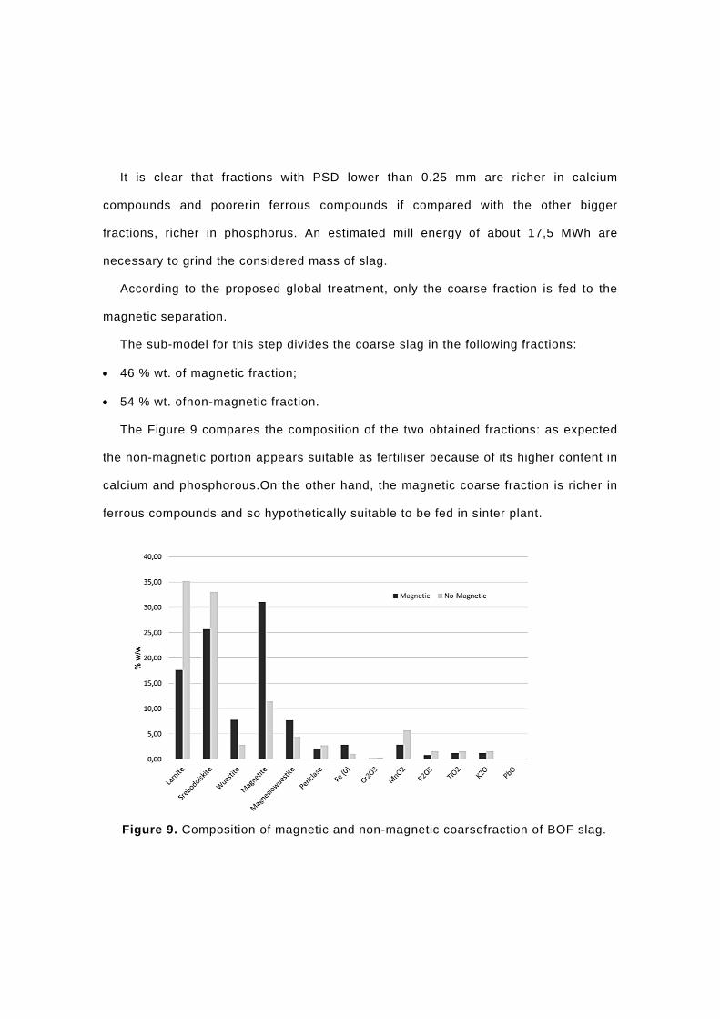
The Figure 9 compares the composition of the two obtained fractions: as expected
the non-magnetic portion appears suitable as fertiliser because of its higher content in
calcium and phosphorous.On the other hand, the magnetic coarse fraction is richer in
ferrous compounds and so hypothetically suitable to be fed in sinter plant.
Figure 9. Composition of magnetic and non-magnetic coarsefraction of BOF slag.
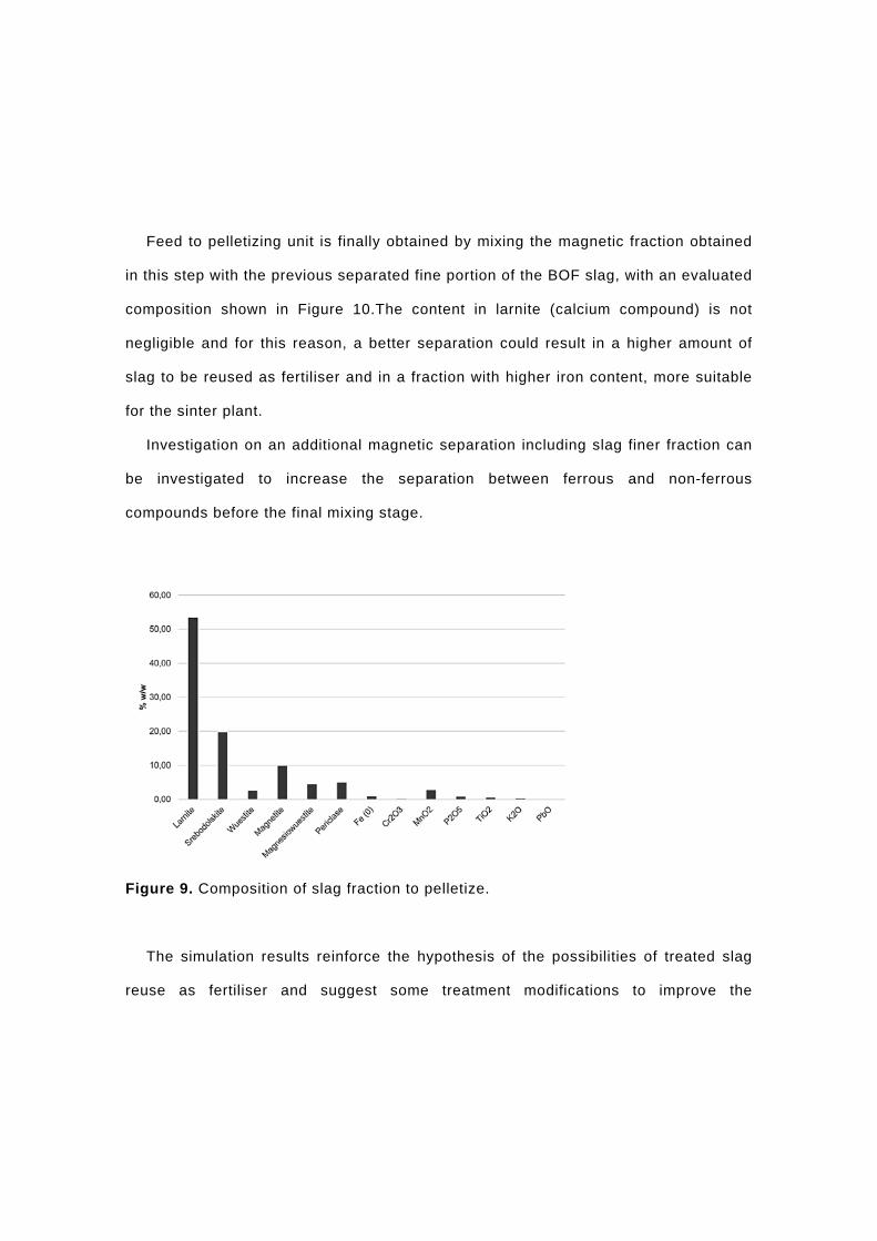
Feed to pelletizing unit is finally obtained by mixing the magnetic fraction obtained
in this step with the previous separated fine portion of the BOF slag, with an evaluated
composition shown in Figure 10.The content in larnite (calcium compound) is not
negligible and for this reason, a better separation could result in a higher amount of
slag to be reused as fertiliser and in a fraction with higher iron content, more suitable
for the sinter plant.
Investigation on an additional magnetic separation including slag finer fraction can
be investigated to increase the separation between ferrous and non-ferrous
compounds before the final mixing stage.
Figure 9. Composition of slag fraction to pelletize.
The simulation results reinforce the hypothesis of the possibilities of treated slag
reuse as fertiliser and suggest some treatment modifications to improve the
separation efficiency between magnetic and non-magnetic materials.
Conclusion
A BOF slag recovery option has been investigated by combining experimental data
collection and process simulation. The presented Excel-based model represents each
stage of the selected BOF slag treatment process, according to ILVA tests. Model,
such as each contained sub-model, can be used to test treatment behaviour with
different slag qualities and treatments operating conditions. Simulation results are
similar to experimental and lab test data for the analysed case study.
The obtained final fractions have features that fit with requirements for reuse as
fertiliser and pellettization operations, with adjustments in magnetic separation
operation.
Results show a preliminary proof of possibility for BOF slag reuse, encouraging for
further studies and investigations.
Acknowledgments
The work described in the present paper has been developed within the projects
entitled “Efficient use of resources in steel plants through process integration”
(Contract No. RFSR-CT-2012-00039) and “Removal of Phosphorus from BOF-slag”
(RFSR-CT-2013-0032) and that have received funding from the Research Fund for
Coal and Steel of the European Union. The sole responsibility of the issues treated in
the present paper lies with the authors; the Commission is not responsible for any use
that may be made of the information contained therein.
References

Birat, J.-P. (2009) Steel and CO2–the ULCOS program, CCS and mineral carbonation
using steelmaking slag. Proceedings of the 1 st International Slag Valorization
Symposium, pp. 6-7.
Branca, T.A., Colla, V., Valentini, R. (2009) A way to reduce environmental impact of
ladle furnace slag, Ironmaking & Steelmaking, 36, 597-602.
Branca, T.A., Pistocchi, C., Colla, V., Ragaglini, G., Amato, A., Tozzini, C.,
Mudersbach, D., Morillon, A., Rex, M., Romaniello, L. (2014) Investigation of (BOF)
Converter slag use for agriculture in Europe, Metallurgical Research & Technology,
111, 155-167.
Das, B., Prakash, S., Reddy, P., Misra, V. (2007) An overview of utilization of slag and
sludge from steel industries, Resources, conservation and recycling, 50, 40-57.
Dippenaar, R. (2005) Industrial uses of slag (the use and re-use of iron and
steelmaking slags), Ironmaking & Steelmaking, 32, 35-46.
E. Commission, Directive 2008/98/EC of the European Parliament and of the Council
of 19 November 2008 on waste and repealing certain directives (Waste framework
directive, R1 formula in footnote of attachment II): http://eur-lex. europa.
eu/LexUriServ, LexUriServ. do, (2008).
Jankovic, A., Dundar, H., Mehta, R. (2010) Relationships between comminution

energy and product size for a magnetite ore, Journal of the South African Institute of
Mining & Metallurgy, 110.3, 141.
Larsson, M., Wang, C., Dahl, J., Wedholm, A., Samuelsson, C., Magnusson, M.,
Lampinen, H.O, Su, F., Grip, C.E. (2006) Improved energy and material efficiency
using new tools for global optimisation of residue material flows, International journal
of green energy, 3, 127-137.
Ma, N., Houser, J.B. (2014) Recycling of steelmaking slag fines by weak magnetic
separation coupled with selective particle size screening, Journal of Cleaner
Production, 82, 221-231.
Matino, I., Alcamisi, E., Porzio, G.F., Colla, V., Romaniello, L. (2014) Modelling of oily
millscale and sludge treatment process for improved by-product recovery and waste
minimization in steel industry, in: 1st International Process Integration Forum for the
Steel Industry, Swerea MEFOS, 2014.
Mindat:http://www.mindat.org/
Mineral Data Publishing v.1,v.1.2 (2001-2005).
O'Sullivan, C.T. (1990) Newton's law of cooling - A critical assessment, American
Journal of Physics, 58, 956.

Pistocchi, C., Ragaglini, G., Branca, T.A., Bonari, E., Colla, V. (2012) Use of BOF
steel slag in agriculture: column test evaluation of effects on alkaline soils and
drainage water. Proceedings of the 7th Conference on Sustainable Development of
Energy, Water and Environment System, Faculty of Mechanical Engineering and Naval
Architecture.
Proctor, D., Fehling, K., Shay, E., Wittenborn, J., Green, J., Avent, C., Bigham, R.,
Connolly, M., Lee, B., Shepker, T. (2000) Physical and chemical characteristics of
blast furnace, basic oxygen furnace, and electric arc furnace steel industry slags,
Environmental Science & Technology, 34, 1576-1582.
Saeidi, N., Azizi, D., Noaparast, M., Aslani, S., Ramadi, R. (2013) A developed
approach based on grinding time to determine ore comminution properties, Journal of
Mining and Environment, 4.2, 105-112.
The European Slag Association (2012), Position Paper on the Status of Ferrous Slag,
complying with the Waste Framework Directive (Articles 5/6).
Tsakalakis, K. G., Bond work index tables (wi) from various sources.
Venkateswaran, D., Sharma, D., Muhmood, L., Vitta, S. (2007) Treatment and
characterisation of electric arc furnace (EAF) slag for its effective utilisation in
cementitious products.
Wang, D., Jiang, M., Liu, C., Min, Y., Cui, Y., Liu, J., Zhang, Y. (2012) Enrichment of
Fe‐Containing Phases and Recovery of Iron and Its Oxides by Magnetic Separation
from BOF Slags, steel research international, 83, 189-196.
World Steel Association (2010), Steel Industry By-Products - Project group report
2007-2009.
World Steel Association: https://www.worldsteel.org/